EP3294397B1 - System for inhibiting biofilm formation on catheters - Google Patents
System for inhibiting biofilm formation on catheters Download PDFInfo
- Publication number
- EP3294397B1 EP3294397B1 EP16792311.9A EP16792311A EP3294397B1 EP 3294397 B1 EP3294397 B1 EP 3294397B1 EP 16792311 A EP16792311 A EP 16792311A EP 3294397 B1 EP3294397 B1 EP 3294397B1
- Authority
- EP
- European Patent Office
- Prior art keywords
- oil
- catheter
- wall
- lumen
- lumens
- Prior art date
- Legal status (The legal status is an assumption and is not a legal conclusion. Google has not performed a legal analysis and makes no representation as to the accuracy of the status listed.)
- Active
Links
Images


Classifications
-
- A—HUMAN NECESSITIES
- A61—MEDICAL OR VETERINARY SCIENCE; HYGIENE
- A61M—DEVICES FOR INTRODUCING MEDIA INTO, OR ONTO, THE BODY; DEVICES FOR TRANSDUCING BODY MEDIA OR FOR TAKING MEDIA FROM THE BODY; DEVICES FOR PRODUCING OR ENDING SLEEP OR STUPOR
- A61M25/00—Catheters; Hollow probes
- A61M25/0021—Catheters; Hollow probes characterised by the form of the tubing
- A61M25/0023—Catheters; Hollow probes characterised by the form of the tubing by the form of the lumen, e.g. cross-section, variable diameter
- A61M25/0026—Multi-lumen catheters with stationary elements
-
- A—HUMAN NECESSITIES
- A61—MEDICAL OR VETERINARY SCIENCE; HYGIENE
- A61L—METHODS OR APPARATUS FOR STERILISING MATERIALS OR OBJECTS IN GENERAL; DISINFECTION, STERILISATION OR DEODORISATION OF AIR; CHEMICAL ASPECTS OF BANDAGES, DRESSINGS, ABSORBENT PADS OR SURGICAL ARTICLES; MATERIALS FOR BANDAGES, DRESSINGS, ABSORBENT PADS OR SURGICAL ARTICLES
- A61L29/00—Materials for catheters, medical tubing, cannulae, or endoscopes or for coating catheters
- A61L29/02—Inorganic materials
-
- A—HUMAN NECESSITIES
- A61—MEDICAL OR VETERINARY SCIENCE; HYGIENE
- A61L—METHODS OR APPARATUS FOR STERILISING MATERIALS OR OBJECTS IN GENERAL; DISINFECTION, STERILISATION OR DEODORISATION OF AIR; CHEMICAL ASPECTS OF BANDAGES, DRESSINGS, ABSORBENT PADS OR SURGICAL ARTICLES; MATERIALS FOR BANDAGES, DRESSINGS, ABSORBENT PADS OR SURGICAL ARTICLES
- A61L29/00—Materials for catheters, medical tubing, cannulae, or endoscopes or for coating catheters
- A61L29/14—Materials characterised by their function or physical properties, e.g. lubricating compositions
- A61L29/16—Biologically active materials, e.g. therapeutic substances
-
- A—HUMAN NECESSITIES
- A61—MEDICAL OR VETERINARY SCIENCE; HYGIENE
- A61M—DEVICES FOR INTRODUCING MEDIA INTO, OR ONTO, THE BODY; DEVICES FOR TRANSDUCING BODY MEDIA OR FOR TAKING MEDIA FROM THE BODY; DEVICES FOR PRODUCING OR ENDING SLEEP OR STUPOR
- A61M25/00—Catheters; Hollow probes
- A61M25/0017—Catheters; Hollow probes specially adapted for long-term hygiene care, e.g. urethral or indwelling catheters to prevent infections
-
- A—HUMAN NECESSITIES
- A61—MEDICAL OR VETERINARY SCIENCE; HYGIENE
- A61M—DEVICES FOR INTRODUCING MEDIA INTO, OR ONTO, THE BODY; DEVICES FOR TRANSDUCING BODY MEDIA OR FOR TAKING MEDIA FROM THE BODY; DEVICES FOR PRODUCING OR ENDING SLEEP OR STUPOR
- A61M25/00—Catheters; Hollow probes
- A61M25/0043—Catheters; Hollow probes characterised by structural features
- A61M25/0045—Catheters; Hollow probes characterised by structural features multi-layered, e.g. coated
-
- A—HUMAN NECESSITIES
- A61—MEDICAL OR VETERINARY SCIENCE; HYGIENE
- A61M—DEVICES FOR INTRODUCING MEDIA INTO, OR ONTO, THE BODY; DEVICES FOR TRANSDUCING BODY MEDIA OR FOR TAKING MEDIA FROM THE BODY; DEVICES FOR PRODUCING OR ENDING SLEEP OR STUPOR
- A61M25/00—Catheters; Hollow probes
- A61M25/0067—Catheters; Hollow probes characterised by the distal end, e.g. tips
- A61M25/0068—Static characteristics of the catheter tip, e.g. shape, atraumatic tip, curved tip or tip structure
- A61M25/007—Side holes, e.g. their profiles or arrangements; Provisions to keep side holes unblocked
-
- A—HUMAN NECESSITIES
- A61—MEDICAL OR VETERINARY SCIENCE; HYGIENE
- A61M—DEVICES FOR INTRODUCING MEDIA INTO, OR ONTO, THE BODY; DEVICES FOR TRANSDUCING BODY MEDIA OR FOR TAKING MEDIA FROM THE BODY; DEVICES FOR PRODUCING OR ENDING SLEEP OR STUPOR
- A61M25/00—Catheters; Hollow probes
- A61M25/10—Balloon catheters
- A61M25/1025—Connections between catheter tubes and inflation tubes
-
- A—HUMAN NECESSITIES
- A61—MEDICAL OR VETERINARY SCIENCE; HYGIENE
- A61L—METHODS OR APPARATUS FOR STERILISING MATERIALS OR OBJECTS IN GENERAL; DISINFECTION, STERILISATION OR DEODORISATION OF AIR; CHEMICAL ASPECTS OF BANDAGES, DRESSINGS, ABSORBENT PADS OR SURGICAL ARTICLES; MATERIALS FOR BANDAGES, DRESSINGS, ABSORBENT PADS OR SURGICAL ARTICLES
- A61L2300/00—Biologically active materials used in bandages, wound dressings, absorbent pads or medical devices
- A61L2300/20—Biologically active materials used in bandages, wound dressings, absorbent pads or medical devices containing or releasing organic materials
- A61L2300/22—Lipids, fatty acids, e.g. prostaglandins, oils, fats, waxes
-
- A—HUMAN NECESSITIES
- A61—MEDICAL OR VETERINARY SCIENCE; HYGIENE
- A61L—METHODS OR APPARATUS FOR STERILISING MATERIALS OR OBJECTS IN GENERAL; DISINFECTION, STERILISATION OR DEODORISATION OF AIR; CHEMICAL ASPECTS OF BANDAGES, DRESSINGS, ABSORBENT PADS OR SURGICAL ARTICLES; MATERIALS FOR BANDAGES, DRESSINGS, ABSORBENT PADS OR SURGICAL ARTICLES
- A61L2300/00—Biologically active materials used in bandages, wound dressings, absorbent pads or medical devices
- A61L2300/40—Biologically active materials used in bandages, wound dressings, absorbent pads or medical devices characterised by a specific therapeutic activity or mode of action
- A61L2300/452—Lubricants
-
- A—HUMAN NECESSITIES
- A61—MEDICAL OR VETERINARY SCIENCE; HYGIENE
- A61M—DEVICES FOR INTRODUCING MEDIA INTO, OR ONTO, THE BODY; DEVICES FOR TRANSDUCING BODY MEDIA OR FOR TAKING MEDIA FROM THE BODY; DEVICES FOR PRODUCING OR ENDING SLEEP OR STUPOR
- A61M25/00—Catheters; Hollow probes
- A61M25/0021—Catheters; Hollow probes characterised by the form of the tubing
- A61M25/0023—Catheters; Hollow probes characterised by the form of the tubing by the form of the lumen, e.g. cross-section, variable diameter
- A61M25/0026—Multi-lumen catheters with stationary elements
- A61M2025/0036—Multi-lumen catheters with stationary elements with more than four lumina
-
- A—HUMAN NECESSITIES
- A61—MEDICAL OR VETERINARY SCIENCE; HYGIENE
- A61M—DEVICES FOR INTRODUCING MEDIA INTO, OR ONTO, THE BODY; DEVICES FOR TRANSDUCING BODY MEDIA OR FOR TAKING MEDIA FROM THE BODY; DEVICES FOR PRODUCING OR ENDING SLEEP OR STUPOR
- A61M25/00—Catheters; Hollow probes
- A61M25/0021—Catheters; Hollow probes characterised by the form of the tubing
- A61M25/0023—Catheters; Hollow probes characterised by the form of the tubing by the form of the lumen, e.g. cross-section, variable diameter
- A61M25/0026—Multi-lumen catheters with stationary elements
- A61M2025/0037—Multi-lumen catheters with stationary elements characterized by lumina being arranged side-by-side
-
- A—HUMAN NECESSITIES
- A61—MEDICAL OR VETERINARY SCIENCE; HYGIENE
- A61M—DEVICES FOR INTRODUCING MEDIA INTO, OR ONTO, THE BODY; DEVICES FOR TRANSDUCING BODY MEDIA OR FOR TAKING MEDIA FROM THE BODY; DEVICES FOR PRODUCING OR ENDING SLEEP OR STUPOR
- A61M25/00—Catheters; Hollow probes
- A61M25/0021—Catheters; Hollow probes characterised by the form of the tubing
- A61M25/0023—Catheters; Hollow probes characterised by the form of the tubing by the form of the lumen, e.g. cross-section, variable diameter
- A61M25/0026—Multi-lumen catheters with stationary elements
- A61M2025/004—Multi-lumen catheters with stationary elements characterized by lumina being arranged circumferentially
-
- A—HUMAN NECESSITIES
- A61—MEDICAL OR VETERINARY SCIENCE; HYGIENE
- A61M—DEVICES FOR INTRODUCING MEDIA INTO, OR ONTO, THE BODY; DEVICES FOR TRANSDUCING BODY MEDIA OR FOR TAKING MEDIA FROM THE BODY; DEVICES FOR PRODUCING OR ENDING SLEEP OR STUPOR
- A61M25/00—Catheters; Hollow probes
- A61M25/0043—Catheters; Hollow probes characterised by structural features
- A61M25/0045—Catheters; Hollow probes characterised by structural features multi-layered, e.g. coated
- A61M2025/0046—Coatings for improving slidability
- A61M2025/0047—Coatings for improving slidability the inner layer having a higher lubricity
- A61M2025/0048—Coatings for improving slidability the inner layer having a higher lubricity with an outer layer made from silicon
-
- A—HUMAN NECESSITIES
- A61—MEDICAL OR VETERINARY SCIENCE; HYGIENE
- A61M—DEVICES FOR INTRODUCING MEDIA INTO, OR ONTO, THE BODY; DEVICES FOR TRANSDUCING BODY MEDIA OR FOR TAKING MEDIA FROM THE BODY; DEVICES FOR PRODUCING OR ENDING SLEEP OR STUPOR
- A61M25/00—Catheters; Hollow probes
- A61M25/0043—Catheters; Hollow probes characterised by structural features
- A61M2025/0056—Catheters; Hollow probes characterised by structural features provided with an antibacterial agent, e.g. by coating, residing in the polymer matrix or releasing an agent out of a reservoir
-
- A—HUMAN NECESSITIES
- A61—MEDICAL OR VETERINARY SCIENCE; HYGIENE
- A61M—DEVICES FOR INTRODUCING MEDIA INTO, OR ONTO, THE BODY; DEVICES FOR TRANSDUCING BODY MEDIA OR FOR TAKING MEDIA FROM THE BODY; DEVICES FOR PRODUCING OR ENDING SLEEP OR STUPOR
- A61M25/00—Catheters; Hollow probes
- A61M25/0021—Catheters; Hollow probes characterised by the form of the tubing
- A61M25/0023—Catheters; Hollow probes characterised by the form of the tubing by the form of the lumen, e.g. cross-section, variable diameter
-
- A—HUMAN NECESSITIES
- A61—MEDICAL OR VETERINARY SCIENCE; HYGIENE
- A61M—DEVICES FOR INTRODUCING MEDIA INTO, OR ONTO, THE BODY; DEVICES FOR TRANSDUCING BODY MEDIA OR FOR TAKING MEDIA FROM THE BODY; DEVICES FOR PRODUCING OR ENDING SLEEP OR STUPOR
- A61M25/00—Catheters; Hollow probes
- A61M25/0067—Catheters; Hollow probes characterised by the distal end, e.g. tips
- A61M25/0074—Dynamic characteristics of the catheter tip, e.g. openable, closable, expandable or deformable
Definitions
- the present invention relates to inhibiting biofilm formation on catheters and other implants or indwelling devices.
- biofilms are typically resistant to antibiotics.
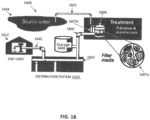
- Biofilm formation is also a problem in water distribution systems, such as that shown in FIG. 16 .
- These treatment systems 1600 are formed of pipes 1602 that extend from a water source 1604, to a treatment system 1606 (which includes multiple filter 1607a and disinfectant units 1607b) to a storage tank 1608, to a distribution system 1610. before entering the plumbing system and outlet of 1612 of the end user, such as a domestic consumer.
- Biofilms can also form in industrial water and sewer transport pipes, as well as in brine and waste-water transport tankers and pipes, In addition, biofilm formation in water reservoirs, water based liquid food transporting tankers, trucks and ship hulls may create a serious health problem.
- Biofilms are an ideal media for harboring legionella microbes that contaminate water supplies, as they protect bacteria against disinfectants, other anti microbial agents.
- biofilms When biofilms are in municipal water systems, they include for example, aggregates of microorganisms, such as bacteria, fungi, diatoms, protozoa, algae, and any exogenous materials, which are embedded in a hydrated extracellular matrix and attached to a solid surface, such as that of the pipes 1602 and filters of the Treatment System 1606.
- These biofilms also include live and dead bacteria, as well as organic and inorganic matter.
- biofilms cause conditions such as pipe fouling, as seen in the food industry, papermills, water distribution systems, cooling towers.
- Biofilms negatively affect industrial settings, causing corrosion and lime scale buildup. When in pipes, the corrosion and lime scale reduces liquid flow through the pipe, as well as reduces thermal conduction from the
- catheters and other indwelling devices include a lumen and/or cavity coupled with a wall configured for holding oils, such as mineral oil and other oil-based substances (collectively "oil” or “oils” as used throughout this document), while allowing the oil to leach through the wall of the catheter or device to the surface, the oil at the surface creating a smooth surface (e.g., coating on the surface) with zero stress inhibiting and/or preventing biofilm formation, hence, significantly lowering the possibility for biofilm and bacterial adhesions on the catheter or device and causing infections.
- the walls are such that they are of materials at various thicknesses and porosities to allow for oil leaching therethrough.
- the catheters and devices of the present disclosure and not forming part of the invention typically include a method to create smooth exterior surfaces, as biofilm growth tends to be inhibited by such smooth surfaces, due to their being zero stress on these surfaces.
- the present disclosure and not forming part of the invention creates articles, such as tubes, conduits, pipes and other devices, of silicone walls/channels/cells, that based on the natural and/or modified porosity of the silicone, allows oil to leach from within the tubes/channels/cells to the article surface, to prevent, inhibit or otherwise delay biofilm formation.
- the present disclosure and not forming part of the invention is also usable in municipal water systems, along with other systems which transport water and other materials.
- the present disclosure and not forming part of the invention provides a clean, safe and sanitized water supply, which is important in ensuring public health.
- the present disclosure and not forming part of the invention serves to effectively reduce biofilm build-up, as-well-as scale build-up which serve as sites for hosting harmful pathogens such as E. coli, Pseudomonas or Salmonella. This is especially true in water carrying pipes and water reservoirs, for assuring public health.
- the present disclosure and not forming part of the invention provides oily surfaces, for example, in pipes and other conduits, which carry liquids and the like, which increase flow velocity and shear force to biofilms and decrease sedimentation.
- water based liquids move efficiently through the aforementioned pipes and conduits, treated or constructed in accordance with the invention, than with conventional pipes. Accordingly, the disclosure and not forming part of the invention reduces deposits which gives rise to biofilm formation and buildup.
- the body further includes a central lumen extending through the body wherein plurality of lumens are positioned intermediate the central lumen and the outer wall of the body, the portion of the central lumen bordering the plurality of lumens defining an inner wall configured for accommodating oil leaching through the inner wall and onto the inner surface of the central lumen.
- the oil includes oil-based substances.
- the oil includes oil-based substances.
- Examples of the present disclosure and not forming part of the invention are directed to a device, for example, for preventing biofilm formation.
- the device comprises: a double layer membrane configured for leaching oil therethrough, in which oil is filled between the layers.
- the oil includes oil-based substances.
- the double layer membrane is of a porosity to accommodate oil leaching therethrough to the surface of the device.
- the channels are oriented substantially parallel to each other and extend along the length of the outer tubular member.
- the outer tubular member and the inner surface are coextruded.
- the conduit includes at least one of tubes and pipes.
- the catheter 100 is, for example, a self-retaining urinary catheter, such as a "Foley" catheter.
- the catheter 100 includes a proximal end 100p, and distal end 100d.
- the distal end 100d of the catheter 100 which also defines the distal end 102d of the body 102, is, for example, for positioning inside the requisite body opening, tube, orifice, or the like, while the proximal end 100p, which includes a connector 110, that attaches to the body 102 (at the proximal end 102p of the body 102), remains outside of the human or animal body.
- the catheter 100 includes a body 102, which supports a balloon 104 (shown in an inflated state) and includes an opening 106 to the ambient environment (through which urine and other bodily fluids enter the catheter 100 for drainage) at a tip 108, formed at the distal end 100d.
- the body 102 at its distal end 102d, terminates at the tip 108, with the tip 108 defining the distal end 100d of the catheter 100.
- the ports 130-133 include a central port 130 and central lumen 130a, through which the central lumen 140 of the body 102 is accessed.
- Outer ports 131-133 include an oil filling port 131 and lumen 131a, through which oil for the oil filling lumen 141 enters the catheter 100, an air vent 132 including a lumen 132a joining to lumens 142 by the upper manifold 150b for air outflow through the vent (as shown in FIG. 2C ), a balloon port 133 and lumen 133a, through which the balloon lumen 143 is accessed (for example, by instrumentation) for inflating and deflating the balloon 104.
- the lumens 140, 141, 142 and 143 include a central or inner lumen 140, through which body fluid drained, surrounded, for example, by outer lumens 141, 142, associated with oil, and 143 for air for inflating the balloon 104. While plural (several) outer lumens 141, 142, 143 are shown any number of outer lumens is sufficient, provided there is a system for maintaining oil in the catheter 100 walls (inner and outer), so as to allow for oil coating of the corresponding inner and/or outer surfaces of the catheter 100.
- lumens 143 associated with inflating and deflating the balloon 104. While the inner 140 and outer lumens 141, 142, 143 are shown as straight, extending at least substantially parallel to each other along the length of the catheter 100, any one or more of the lumens 140-143 may be curved, circular, undulating, or other irregular shape, for example, as shown in FIGs. 5A and 5B .
- FIG. 6D and 6E show an outer surface with longitudinal indentations for increasing the surface of the body to be covered with the leaching oil. Similar indentations can be along the inner surface of the body for the same purpose.
- FIGs. 7A-7C shown an alternative embodiment body 702 for the catheter 100.
- the outer tube 704 receives an inner core 706.
- the inner core 706 includes a central lumen 140, and a balloon inflation lumen 143, and as inserted into the outer tube 704 defines the oil filling 141 and oil lumens 142.
- FIGs. 8A-8C shown an alternative embodiment body 802 for the catheter 100.
- the outer tube 804 receives and inner core 806.
- the inner core 806 includes a central lumen 140.
- the core 806 defines the oil filling 141, oil lumens 142, and at least one balloon inflation lumen 143.
- the inner cores 706, 806 and the outer tubes 704, 804 of the embodiments of FIGs. 7A-7C and 8A-8C may be from the same material or different materials to control the oil leaching and device flexibility.
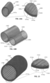
- FIGs. 9A and 9B show the tip 108 of the catheter 100.
- the tip 108 includes an outer portion 901 and an inner portion 902.
- the inner portion 902 includes a manifold 150a which connects all oil lumens 141, 142, such that oil from the oil filling lumen(s) 141 reaches the manifold 150a and flows into all of the one or more oil lumens 142, of the catheter body 102.
- the tip 108 includes the opening 106, single or multiple, through which urine and/or body fluids enter into the central lumen 140 of the body 102 for drainage, and has a spherical-like or rounded head 906.
- Additional mico-pores may be drilled on the outer wall 102x and the outer tube 704, 804, as well as in the inner lumen wall for example, in portions which are the oil lumens 141, 142. These additional pores promote oil leaching through the outer wall 102x and outer tubes 706, 806 as well as the inner lumen. These pores range from approximately 2 microns to approximately 50 microns and allow control of the amount of oil to leach.
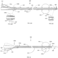
- FIGs. 14A and 14B show tubes 1400 in accordance with examples of the present disclosure not forming part of the invention, which may be used as pipes, conduits and the like for carrying water and other water-based liquids.
- the tubes 1400 are typically of an outer tube 1402, which defines an outer layer, and an inner tube 1404, which when in the outer tube 1002, defines an intermediate layer or tube 1406, and an inner layer or tube 1408.
- the inner layer 1408 includes channels 1410, which are expandable, from an initially flat orientation to a rounded shape, when the internal lumens 1410a are filled with oil.
- FIG. 15 shows a pipe 1500 formed of an outer tube 1502 and an inner surface 1508, formed of channels 1510, for example, longitudinal, spiraling (coiled) or zig-zaging channels, defining lumens 1510a, similar to the inner layer 1408 and channels 1410 of the tubes 1400 detailed in FIGS. 14A and 14B above.
- the channels 1510, in the lumens 1510a are designed to be filled with oil, and are of a material, with a thickness and porosity, which allows the oil to leach or penetrate the inner layer 1408, and coats the inner surface 1510x of the tube 1500, similar to that detailed for tubes 704, 804, above.
- the inner layer 1508 is, for example, in a flat orientation, with the channels 1510 becoming rounded, when the lumens 1510a are filled with oil.
- the outer tube 1502 is, for example, of a polymeric material.
- the inner tube 1508, with the channels 1510, is, for example, made of the aforementioned Silastic ® Elastomer, available from Dow Coming.
- the outer tube 1502 may also be a polymeric pipe, coextruded with the material of the inner layer 1508.
Landscapes
- Health & Medical Sciences (AREA)
- Life Sciences & Earth Sciences (AREA)
- Animal Behavior & Ethology (AREA)
- Veterinary Medicine (AREA)
- Public Health (AREA)
- General Health & Medical Sciences (AREA)
- Engineering & Computer Science (AREA)
- Biomedical Technology (AREA)
- Heart & Thoracic Surgery (AREA)
- Pulmonology (AREA)
- Hematology (AREA)
- Anesthesiology (AREA)
- Biophysics (AREA)
- Epidemiology (AREA)
- Chemical & Material Sciences (AREA)
- Medicinal Chemistry (AREA)
- Molecular Biology (AREA)
- Inorganic Chemistry (AREA)
- Child & Adolescent Psychology (AREA)
- Urology & Nephrology (AREA)
- Materials For Medical Uses (AREA)
- Media Introduction/Drainage Providing Device (AREA)
Description
- The present invention relates to inhibiting biofilm formation on catheters and other implants or indwelling devices.
- Biofilms are complex aggregations of microorganisms which grow on a solid surface or matrix which appeared on the Earth 4.5 billion years ago. For example, biofilms typically form on the surfaces of indwelling catheters and other indwelling devices or implants. It is estimated that 65% of the bacterial infections treated in hospitals are caused by bacterial biofilms.
- These biofilms are typically resistant to antibiotics. Currently, there are not any proven effective strategies, which prevent/inhibit biofilm formation.
- Biofilm formation causes chronic infection for people who require regular catheterizations or have implanted devices. This is especially prevalent with urinary catheters. In patients with an indwelling urethral catheter, the daily rate of acquisition of bacteriuria is 3% to 10%, as reported in Saint S, Lipsky B, Goold S., in "Indwelling urinary catheters: a one-point restraint?", Ann. Intern. Med., July 2002, 137(2), pages 125-127 . For example, in the United States alone there are over 200 Million urinary catheterizations in a year, with more than one million reported cases of catheter-associated urinary tract infection (CAUTI). Many of these CAUTI cases involve biofilms forming on the indwelling urinary catheter, the biofilms consisting of adherent microorganisms, their extracellular products, and host components, all of which are deposited on the catheter. These biofilms cause persistent infections that are resistant to antimicrobial therapy, for which proven effective strategies for prevention CAUTI or other biofilm caused infections from catheterization are presently lacking.
- Attempts have been made to inhibit bacterial growth from catheters by impregnating urinary catheters with antimicrobial agents, such as nitrofurazone. However, these treated catheters merely delayed the onset of bacteriuria in chronically catheterized patients, as reported in Johnson J, et al., in "Activities of a nitrofurazone-containing urinary catheter and a silver hydrogel catheter against multidrug-resistant bacteria characteristic of catheter-associated urinary tract infection", Antimicrob. Agents Chemother. 1999 Dec. 43(12), pages 2990-2995 . Accordingly, this was a potentially effective solution in preventing bacteriuria for patients undergoing short-term catheterization, but failed to be effective over the long term, with chronically catheterized patients.
- Additionally, attempts were made to coat catheters with impregnated agents. However, these coatings tend to wear off, become covered with dirt, ultimately becoming ineffective. Other attempts at treating catheters to make them bactericidal, have included, modifying the polymeric surface of polymeric catheters through glow discharge techniques, as well as making the catheters of various combinations of polymeric materials. However, the problems associated with biofilm bacteria remain.
- Biofilm formation is also a problem in water distribution systems, such as that shown in
FIG. 16 . Thesetreatment systems 1600 are formed ofpipes 1602 that extend from awater source 1604, to a treatment system 1606 (which includesmultiple filter 1607a anddisinfectant units 1607b) to astorage tank 1608, to adistribution system 1610. before entering the plumbing system and outlet of 1612 of the end user, such as a domestic consumer. Biofilms can also form in industrial water and sewer transport pipes, as well as in brine and waste-water transport tankers and pipes, In addition, biofilm formation in water reservoirs, water based liquid food transporting tankers, trucks and ship hulls may create a serious health problem. - Biofilms are an ideal media for harboring legionella microbes that contaminate water supplies, as they protect bacteria against disinfectants, other anti microbial agents. When biofilms are in municipal water systems, they include for example, aggregates of microorganisms, such as bacteria, fungi, diatoms, protozoa, algae, and any exogenous materials, which are embedded in a hydrated extracellular matrix and attached to a solid surface, such as that of the
pipes 1602 and filters of theTreatment System 1606. These biofilms also include live and dead bacteria, as well as organic and inorganic matter. - These biofilms cause conditions such as pipe fouling, as seen in the food industry, papermills, water distribution systems, cooling towers. Moreover, Biofilms negatively affect industrial settings, causing corrosion and lime scale buildup. When in pipes, the corrosion and lime scale reduces liquid flow through the pipe, as well as reduces thermal conduction from the
- The invention is defined in claim 1. Preferable embodiments are defined in the dependent claims. According to the present invention, catheters and other indwelling devices include a lumen and/or cavity coupled with a wall configured for holding oils, such as mineral oil and other oil-based substances (collectively "oil" or "oils" as used throughout this document), while allowing the oil to leach through the wall of the catheter or device to the surface, the oil at the surface creating a smooth surface (e.g., coating on the surface) with zero stress inhibiting and/or preventing biofilm formation, hence, significantly lowering the possibility for biofilm and bacterial adhesions on the catheter or device and causing infections. The walls are such that they are of materials at various thicknesses and porosities to allow for oil leaching therethrough. Additionally, the catheters and devices of the present disclosure and not forming part of the invention typically include a method to create smooth exterior surfaces, as biofilm growth tends to be inhibited by such smooth surfaces, due to their being zero stress on these surfaces.
- The present disclosure and not forming part of the invention creates articles, such as tubes, conduits, pipes and other devices, of silicone walls/channels/cells, that based on the natural and/or modified porosity of the silicone, allows oil to leach from within the tubes/channels/cells to the article surface, to prevent, inhibit or otherwise delay biofilm formation.
- The present disclosure and not forming part of the invention is also usable in municipal water systems, along with other systems which transport water and other materials. For example, the present disclosure and not forming part of the invention provides a clean, safe and sanitized water supply, which is important in ensuring public health. The present disclosure and not forming part of the invention serves to effectively reduce biofilm build-up, as-well-as scale build-up which serve as sites for hosting harmful pathogens such as E. coli, Pseudomonas or Salmonella. This is especially true in water carrying pipes and water reservoirs, for assuring public health.
- The present disclosure and not forming part of the invention provides oily surfaces, for example, in pipes and other conduits, which carry liquids and the like, which increase flow velocity and shear force to biofilms and decrease sedimentation. As a result, water based liquids move efficiently through the aforementioned pipes and conduits, treated or constructed in accordance with the invention, than with conventional pipes. Accordingly, the disclosure and not forming part of the invention reduces deposits which gives rise to biofilm formation and buildup.
- Embodiments of the invention are directed to catheters comprising a plurality of lumens extending through the inside of the body. The lumens are bounded at least in part by an outer wall of the body, and, the outer wall of the body is configured for accommodating oil leaching through the outer wall of the body and onto the outer surface of the outer wall of the body wherein the plurality of lumens extend along the outer wall of the body.
- The plurality of lumens extend along the outer wall of the body in at least one of a longitudinal orientation, a spiral orientation, and a zig-zag orientation.
- The plurality of lumens are filled with oil.
- The body further includes a central lumen extending through the body wherein plurality of lumens are positioned intermediate the central lumen and the outer wall of the body, the portion of the central lumen bordering the plurality of lumens defining an inner wall configured for accommodating oil leaching through the inner wall and onto the inner surface of the central lumen.
- Optionally, the oil includes oil-based substances.
- The inner wall and the outer wall are of a material of a porosity to accommodate oil leaching from the inner lumen through the inner wall to the surface of the inner wall and through the outer wall to the surface of the outer wall.
- Examples of the present disclosure and not forming part of the invention are directed to a device, for example, for preventing biofilm formation. The device comprises: an external surface covered with a silicone membrane under which oil is filled, the silicone membrane configured to accommodate the oil leaching therethrough to the surface of the silicon membrane.
- Optionally, the device is at least one of an implantable device or an indwelling device.
- Optionally, the oil includes oil-based substances.
- Optionally, the silicone membrane is of a porosity to accommodate oil leaching therethrough to the surface of the silicone membrane.
- Examples of the present disclosure and not forming part of the invention are directed to a device, for example, for preventing biofilm formation. The device comprises: a double layer membrane configured for leaching oil therethrough, in which oil is filled between the layers.
- Optionally, the membrane includes silicone.
- Optionally, the silicone membrane device is at least one of an implantable device or an indwelling device.
- Optionally, the oil includes oil-based substances.
- Optionally, the double layer membrane is of a porosity to accommodate oil leaching therethrough to the surface of the device.
- Examples of the present disclosure and not forming part of the invention are directed to a conduit. The conduit comprises: an outer tubular member; and, an inner surface including a plurality of channels extending along the tubular member, the inner surface of a material configured for leaching oil therethrough, when the channels are filled with oil.
- Optionally, the channels are oriented substantially parallel to each other and extend along the length of the outer tubular member.
- Optionally, the channels are oriented in a spiraling manner along the length of the outer tubular member.
- Optionally, the channels oriented in a spiraling manner include a single channel oriented in a spiraling manner.
- Optionally, the channels oriented in a spiraling manner include multiple channels oriented in a spiraling manner.
- Optionally, the outer tubular member includes an outer layer in communication with an inner layer defining the inner surface.
- Optionally, the outer tubular member and the inner surface are coextruded.
- Optionally, the channels are filled with oil.
- Optionally, the conduit includes at least one of tubes and pipes.
- Optionally, the material of the conduit is of a porosity for accommodating oil to leach therethrough and coat the inner surface,
- Examples of the present disclosure and not forming part of the invention are also directed to a method for inhibiting biofilm formation in a structure. The method comprises: providing a structure including at least one lumen for holding oil, the structure including at least one member defining a side of the at least one lumen, the at least one member of a material configured for leaching the oil through the at least one member to the outer surface of the at least one member, when the at least one lumen is filled with the oil; and, filling the at least one lumen with oil.
- Optionally, the structure includes at least one of: implantable medical devices, indwelling catheters, medical tubes, medical conduits, non-medical tubes, non-medical conduits and pipes.
- Optionally, the method additionally comprises: deploying the structure to a designated site.
- Optionally, the oil includes oil-based substances.
- Optionally, the oil-based substances include at least one of medical grade mineral oils, mineral oils, and vegetable oils.
- Optionally, the material is of a porosity for accommodating oil to leach therethrough to the outer surface of the material.
- Unless otherwise defined, all technical and/or scientific terms used herein have the same meaning as commonly understood by one of ordinary skill in the art to which the invention pertains.
- Some embodiments of the invention are herein described, by way of example only, with reference to the accompanying drawings, where like reference numerals or characters represent corresponding or like elements. With specific reference now to the drawings in detail, it is stressed that the particulars shown are by way of example and for purposes of illustrative discussion of embodiments of the invention. In this regard, the description taken with the drawings makes apparent to those skilled in the art how embodiments of the invention may be practiced.
- In the drawings:
-
FIG. 1 shows an isometric view of a self-retaining catheter in accordance with embodiments of the present invention; -
FIG. 2A shows a longitudinal cross-section of a self-retaining catheter in accordance with embodiments of the present invention. -
FIG. 2B is a cross-sectional view of the catheter ofFIGs. 1 and 2A , taken alongline 2B-2B ofFIG. 2A ; -
FIG. 2C is a detail view of the vent manifold of the catheter; -
FIG. 3A shows an isometric view of the connector of the catheter ofFIG. 1 ; -
FIG. 3B shows a front view of the connector of the catheter ofFIG. 3A ; -
FIG. 4A shows an isometric view of an alternative embodiment of the connector of the catheter ofFIG. 1 ; -
FIG. 4B shows a front view of the connector of the catheter ofFIG. 4A ; -
FIGs. 5A and 5B are perspective views of a lumen arrangement for a catheter body; -
FIGs. 6A-6J are cross sectional views of alternative lumen arrangements for the catheter body ofFIG. 1 ; -
FIGs. 7A-7C and 8A-8C are cross-sectional views of alternative bodies for the catheter ofFIG. 1 ; -
FIG. 9A is a front view of a tip of the catheter ofFIG. 1 ; -
FIG. 9B is a longitudinal cross-sectional view of the tip ofFIG. 9A taken along line 9B-9B; -
FIG. 10A is a front view of an alternative embodiment of the tip of the catheter ofFIG. 1 ; -
FIG. 10B is a longitudinal cross-sectional view of the tip ofFIG. 10A taken alongline 10B-10B; -
FIG. 11A is a cross-sectional longitudinal view of the catheter ofFIG. 1 and the oil filling lumen of the catheter; -
FIG. 11B is a cross sectional view detailing the vent at the connector of the catheter ofFIG. 11A ; -
FIG. 11C is a cross-sectional view showing the manifold at the tip of the catheter ofFIG. 11A ; -
FIG. 12A is a cross-sectional longitudinal view of the catheter ofFIG. 1 with an alternative embodiment connector ofFIG. 4A ; -
FIG. 12B is a cross sectional view detailing the vent at the connector of the catheter ofFIG. 12A ; -
FIG. 12C is a cross-sectional view showing the manifold at the tip of the catheter ofFIG. 12A ; -
FIG. 13 is a partial cross sectional view of the catheter ofFIG. 1 showing air flow for balloon inflation; -
FIGs. 14A and 14B are cross-sectional perspective views of pipes in accordance with other examples not forming part of the present invention; -
FIGs. 14C and 14D are alternate inner tubes to the inner tube ofFIGs. 14A and 14B ; -
FIG. 15 is a cross-sectional perspective views of a pipe in accordance with other examples the present disclosure not forming part of the invention; and, -
FIG. 16 is a diagram of a water delivery system not forming part of the present invention. - Before explaining at least one embodiment of the invention in detail, it is to be understood that the invention is not necessarily limited in its application to the details of construction and the arrangement of the components set forth in the following description and/or illustrated in the drawings. The invention is capable of other embodiments or of being practiced or carried out in various ways.
-
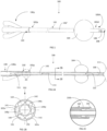
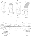
FIG. 1 shows an apparatus, in the exemplary form of acatheter 100, in accordance with embodiments of the present invention. Thiscatheter 100 is exemplary of the present invention, as the present invention is also embodied in other devices, including indwelling or implanted devices for the human and/or animal body. - The
catheter 100 is, for example, a self-retaining urinary catheter, such as a "Foley" catheter. Thecatheter 100 includes aproximal end 100p, anddistal end 100d. Thedistal end 100d of thecatheter 100, which also defines thedistal end 102d of thebody 102, is, for example, for positioning inside the requisite body opening, tube, orifice, or the like, while theproximal end 100p, which includes aconnector 110, that attaches to the body 102 (at theproximal end 102p of the body 102), remains outside of the human or animal body. Thecatheter 100 includes abody 102, which supports a balloon 104 (shown in an inflated state) and includes anopening 106 to the ambient environment (through which urine and other bodily fluids enter thecatheter 100 for drainage) at atip 108, formed at thedistal end 100d. Thebody 102, at itsdistal end 102d, terminates at thetip 108, with thetip 108 defining thedistal end 100d of thecatheter 100. - As shown in
FIG. 2A , urine and other bodily fluids flow through thecatheter 100 in accordance with thearrows 111. The fluids enter thecatheter 100 through theopening 106 in thetip 108, flow through thecentral lumen 140 of thebody 102 of the catheter 100 (shown inFIG. 2B ), and then flow through thelumen 130a of theconnector 110, and leave thecatheter 100 via theport 130. - The
tip 108 typically may be made of a polymeric material, which may be harder than the material for thebody 102, as detailed below. The proximal end of thebody 102p terminates at theconnector 110. - The
connector 110 includes ports 130-133, as shown inFIGs. 3A and 3B , to which attention is also directed. Theconnector 110 is typically made of a polymeric material compatible with the material of thebody 102, and is joined to thebody 102 by conventional materials joining techniques. - The ports 130-133 include a
central port 130 andcentral lumen 130a, through which thecentral lumen 140 of thebody 102 is accessed. Outer ports 131-133 include anoil filling port 131 andlumen 131a, through which oil for theoil filling lumen 141 enters thecatheter 100, anair vent 132 including alumen 132a joining tolumens 142 by theupper manifold 150b for air outflow through the vent (as shown inFIG. 2C ), aballoon port 133 andlumen 133a, through which theballoon lumen 143 is accessed (for example, by instrumentation) for inflating and deflating theballoon 104. -
FIGs. 4A and 4B show an alternative embodiment of the connector 110'. Here, the vent 132', which connects to theupper manifold 150b, extends to the ambient environment (through thevent port 132") from theoil lumens 142 of the body 102 (FIG. 12B ). Similar to that for theconnector 110, theport 130 includes acentral port 130 andcentral lumen 130a, through which thecentral lumen 140 of thebody 102 is accessed.Outer ports oil filling port 131 andlumen 131a, through which oil for theoil filling lumen 141 enters thecatheter 100, and, aballoon port 133 andlumen 133a, through which theballoon lumen 143 is accessed (for example, by instrumentation) for inflating and deflating theballoon 104. - Within the
catheter 100 arelumens FIG. 2B . Thelumens inner lumen 140, through which body fluid drained, surrounded, for example, byouter lumens balloon 104. While plural (several)outer lumens catheter 100 walls (inner and outer), so as to allow for oil coating of the corresponding inner and/or outer surfaces of thecatheter 100. There arelumens 143 associated with inflating and deflating theballoon 104. While the inner 140 andouter lumens catheter 100, any one or more of the lumens 140-143 may be curved, circular, undulating, or other irregular shape, for example, as shown inFIGs. 5A and 5B . -
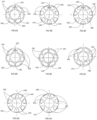
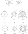
FIGs. 6A-6J show various alternative lumen arrangements in thebody 102. All of these alternative arrangements include at least onecentral lumen 140, for the drainage of body fluids, at least oneoil filling lumen 141 connected to the other lumen/s to be filled with oil, at least oneoil lumen 142, and at least onelumen 143 for air or other substances for inflating theballoon 104. For catheters lacking a balloon structure, all lumens areoil lumens -
FIG. 6D and 6E show an outer surface with longitudinal indentations for increasing the surface of the body to be covered with the leaching oil. Similar indentations can be along the inner surface of the body for the same purpose. -
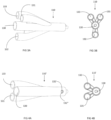
FIGs. 7A-7C shown analternative embodiment body 702 for thecatheter 100. Theouter tube 704 receives aninner core 706. Theinner core 706 includes acentral lumen 140, and aballoon inflation lumen 143, and as inserted into theouter tube 704 defines the oil filling 141 andoil lumens 142. -
FIGs. 8A-8C shown analternative embodiment body 802 for thecatheter 100. Theouter tube 804 receives andinner core 806. Theinner core 806 includes acentral lumen 140. As inserted into theouter tube 804, thecore 806 defines the oil filling 141,oil lumens 142, and at least oneballoon inflation lumen 143. - The
inner cores outer tubes FIGs. 7A-7C and 8A-8C , may be from the same material or different materials to control the oil leaching and device flexibility. -
FIGs. 9A and 9B show thetip 108 of thecatheter 100. Thetip 108 includes anouter portion 901 and aninner portion 902. Theinner portion 902 includes a manifold 150a which connects alloil lumens more oil lumens 142, of thecatheter body 102. Thetip 108 includes theopening 106, single or multiple, through which urine and/or body fluids enter into thecentral lumen 140 of thebody 102 for drainage, and has a spherical-like or rounded head 906. -
FIGs. 10A and 10B show an alternative tip 108' for thecatheter 100. This alternative tip 108' is similar to thetip 108, as detailed above, with similar structures in the corresponding "1000", except that the tip 108' includes a curved head 1006. - The
bodies outer tubes outer walls 102x/outer tubes lumens body 102, and the outer surfaces 704', 804' of the respectiveouter tubes outer wall 102x of thebody 102 and theouter tubes - Similarly, all
other walls 140y of the oil filling 141 andoil 142 lumens bordering thecentral lumen 140 are in accordance (for example, material, thickness, porosity) with the aforementionedouter wall 102x of thebody 102 andouter tubes inner surface 140x of thecentral lumen 140. - The
inner cores outer tubes inner cores catheter body 102,outer tubes cores - Additional mico-pores may be drilled on the
outer wall 102x and theouter tube oil lumens outer wall 102x andouter tubes - The oil used to fill the
oil lumens - The
catheter 100 may be prefilled with oil. In this case, theconnector 110 does not have to be present. Theoil lumen 141 is plugged (locked) to avoid leakage through theoil lumen 141 and out of theproximal end 100p of thecatheter 100. -
FIGs. 11A-11C show oil filling of thecatheter 100, with the oil flow indicated byarrows 152. The oil is filled through theport 131, which travels through thelumen 131a to theoil lumen 141. The oil flows through the manifold 150a at thetip 108. At themanifold 150a, oil enters the one ormore oil lumens 142, with the oil flowing through eachlumen 142 until the oil reaches theupper manifold 150b, which allows for venting the air which was in all of theoil lumens 141, 142) and theport 132. -
FIGs. 12A-12C show oil filling of thecatheter 100 with the alternative connector 110' and the air vent 132', with the oil flow indicated by the arrows 152'. The oil flow is similar to that ofFIGs. 11A-11C with oil flow through theoil lumens 142, The oil is filled through theport 131, which travels through thelumen 131a to theoil lumen 141. The oil flows through the manifold 150a at the tip into theoil lumens 142 until it reaches theupper manifold 150b, which directs air for venting through thevent port 132". -
FIG. 13 shows the inflation of theballoon 104 of thecatheter 100, with inflation air, oils or other oil-based substances, the flow indicated by thearrows 156. A syringe (not shown) introduces air to theport 133 of the connector, where the air (orother balloon 104 inflation substance, flows through theconnector lumen 133a, and then throughlumen 143 to theballoon 104. The air, oil, or oil-based substance, for inflation of theballoon 104, enters theballoon 104 through anopening 104a into theballoon 104 cavity. - While the
catheter 100 is shown as a urinary catheter for urinary applications, such as urine drainage, thecatheter 100 can be easily modified for use in other operations in other body locations and vessels, including other blood vessels, bile ducts and other ducts, and brain passageways and other tubular structures in the body. For example, tubes made in accordance with the invention may be double or other multiple layered tubes. Also, for example, devices may be such that they include polymeric walls, similar to that of theouter walls 102x of thecatheter body 102, with inner or external membranes in which oil, as detailed above, is filled. - The present invention, while shown for human use, is also suitable for animal use.
-
FIGS. 14A, 14B ,14C, 14D and15 , show various exemplary structures for non-medical uses not forming part of the invention. These structures use materials, which are non-toxic and food quality materials. These structures are, for example, tubes, pipes and other conduits, both with multiple cross-sectional shapes, for use in fluid and liquid transport, delivery, storage, and the like. -
FIGs. 14A and 14B show tubes 1400 in accordance with examples of the present disclosure not forming part of the invention, which may be used as pipes, conduits and the like for carrying water and other water-based liquids. Thetubes 1400 are typically of anouter tube 1402, which defines an outer layer, and aninner tube 1404, which when in theouter tube 1002, defines an intermediate layer ortube 1406, and an inner layer ortube 1408. Theinner layer 1408 includeschannels 1410, which are expandable, from an initially flat orientation to a rounded shape, when theinternal lumens 1410a are filled with oil. Theinner layer 1408, for example, thechannels 1410 of thisinner layer 1408 are arranged, in orientations such as longitudinal, spiraling (coiled), such as a single "hard"coil 1408 of tube 1404c (FIG. 14C ), or amultiple spiraling channels 1408 of tube 1404d (FIG. 14D ) or zig-zaging. Theinner layer 1408 is of a material, with a thickness and porosity, which allows the oil to leach or penetrate theinner layer 1408 and coat theinner surface 1410x of thetube 1400, similar to that detailed fortubes - The
outer tube 1402 andintermediate tube 1406 are, for example, of a metal or polymeric material. Theinner tube 1408, with thechannels 1410, is, for example, made of the aforementioned Silastic® Elastomer, available from Dow Coming. The oil used, is, for example, Superla Light Mineral Oil. Other medical grade mineral oils or vegetable oils, as well as oil-based substances are also suitable. Thetubes 1400 are either filled with oil on deployment or pre-filled with oil, or combinations thereof. -
FIG. 15 shows apipe 1500 formed of anouter tube 1502 and aninner surface 1508, formed ofchannels 1510, for example, longitudinal, spiraling (coiled) or zig-zaging channels, defininglumens 1510a, similar to theinner layer 1408 andchannels 1410 of thetubes 1400 detailed inFIGS. 14A and 14B above. Thechannels 1510, in thelumens 1510a, are designed to be filled with oil, and are of a material, with a thickness and porosity, which allows the oil to leach or penetrate theinner layer 1408, and coats theinner surface 1510x of thetube 1500, similar to that detailed fortubes inner layer 1508 is, for example, in a flat orientation, with thechannels 1510 becoming rounded, when thelumens 1510a are filled with oil. - The
outer tube 1502 is, for example, of a polymeric material. Theinner tube 1508, with thechannels 1510, is, for example, made of the aforementioned Silastic® Elastomer, available from Dow Coming. Theouter tube 1502 may also be a polymeric pipe, coextruded with the material of theinner layer 1508. - The oil used, is, for example, Superla Light Mineral Oil. Other medical grade mineral oils or vegetable oils, as well as oil-based substances are also suitable. The
tubes 1500 are either filled with oil on deployment or pre-filled with oil, or combinations thereof. - The structures of
FIGs. 14A, 14B and 15 , while shown as tubes and pipes are also usable in non-medical applications, such as, water transport pipes in municipal water systems, pipes and conduits in water transport tankers and trucks, pipes and conduits in liquid food (i.e., milk) transport tankers, and in brine and waste-water tankers. These structures are also usable as industrial water transport pipes, and sewer transport pipes. - The descriptions of the various embodiments of the present invention have been presented for purposes of illustration, but are not intended to be exhaustive or limited to the embodiments disclosed. Many modifications and variations will be apparent to those of ordinary skill in the art without departing from the scope of the described embodiments. The terminology used herein was chosen to best explain the principles of the embodiments, the practical application or technical improvement over technologies found in the marketplace, or to enable others of ordinary skill in the art to understand the embodiments disclosed herein.
- The word "optionally" is used herein to mean "is provided in some embodiments and not provided in other embodiments". Any particular embodiment of the invention may include a plurality of "optional" features unless such features conflict.
- It is appreciated that certain features of the invention, which are, for clarity, described in the context of separate embodiments, may also be provided in combination in a single embodiment. Conversely, various features of the invention, which are, for brevity, described in the context of a single embodiment, may also be provided separately or in any suitable subcombination or as suitable in any other described embodiment of the invention. Certain features described in the context of various embodiments are not to be considered essential features of those embodiments, unless the embodiment is inoperative without those elements.
- Although the invention has been described in conjunction with specific embodiments thereof, it is evident that modifications will be apparent to those skilled in the art. Accordingly, it is intended to embrace all such alternatives, modifications and variations that fall within the scope of the appended claims.
Claims (15)
- A catheter comprising:
a body (102, 702, 802) including at least a first oil lumen (141) and one or more second oil lumens (142), at least the second oil lumens being bounded at least in part by an outer wall of the body, the outer wall being made of a material selected to allow oil to leach through the outer wall of the body and onto the outer surface of the outer wall of the body, to form a coating on the outer surface of the body, the body being provided with a lower manifold (150a) such that oil from the first oil lumen (141) reaches the lower manifold (150a) and flows into the second oil lumens (142), and the body being further provided with an air vent (132) including a lumen (132a) joined to one or more of the second oil lumens (142) by an upper manifold (150b) to allow air to escape from the first and second oil lumens as the first and second oil lumens are being filled with oil from the oil port (131). - The catheter of claim 1, wherein the lumen (141, 142) extends along the outer wall of the body.
- The catheter of claim 2, wherein the lumen (141, 142) extends along the outer wall of the body in at least one of a longitudinal orientation, a ondulating orientation, and a zig-zag orientation.
- The catheter of any one of claims 1-3, wherein the lumen (141, 142) is filled with oil.
- The catheter of claim 1, wherein the body (102, 702, 802) further includes a central lumen (140) extending through the body, and the at least one internal lumen (141, 142) is positioned intermediate the central lumen (140) and the outer wall of the body, the portion of the central lumen bordering the at least one internal lumen (141, 142) defining an inner wall made of a material selected to allow oil to leach through the inner wall and onto the inner surface of the central lumen in a process involving an interaction between the outer wall material and the oil, to form a coating on the inner surface of the central lumen.
- The catheter of claim 5, wherein the at least one internal lumen (141, 142) is filled with oil.
- The catheter of claim 5, wherein the inner wall and the outer wall are of a material of a porosity to accommodate oil leaching from the inner lumen (141, 142) through the inner wall to the surface of the inner wall and through the outer wall to the surface of the outer wall.
- The catheter according to any one of the previous claims wherein the outer wall of the body is a silicone membrane.
- The catheter of any one of the previous claims, which is at least one of an implantable device or an indwelling device.
- The catheter according to any one of the previous claims adapted to function as an implanted or indwelling device.
- The catheter according to any one of the previous claims comprising: a plurality of channels extending along the tubular member.
- The catheter of claim 11, wherein the channels are oriented substantially parallel to each other and extend along the length of the outer tubular member.
- The catheter of claim 11, wherein one or more of the channels are oriented in a spiraling manner along the length of the outer tubular member.
- The catheter of any one of claims 11-13, wherein the outer tubular member (1402) defines an outer layer in communication with an inner layer (1408) defining the inner surface (1410).
- The catheter of claim 14, wherein the outer tubular member and the inner layer are coextruded.
Applications Claiming Priority (2)
| Application Number | Priority Date | Filing Date | Title |
|---|---|---|---|
| US201562160651P | 2015-05-13 | 2015-05-13 | |
| PCT/IL2016/050502 WO2016181397A1 (en) | 2015-05-13 | 2016-05-11 | System for inhibiting biofilm formation on catheters, other indwelling or implantable devices and other devices |
Publications (3)
| Publication Number | Publication Date |
|---|---|
| EP3294397A1 EP3294397A1 (en) | 2018-03-21 |
| EP3294397A4 EP3294397A4 (en) | 2019-01-16 |
| EP3294397B1 true EP3294397B1 (en) | 2024-07-10 |
Family
ID=57247813
Family Applications (1)
| Application Number | Title | Priority Date | Filing Date |
|---|---|---|---|
| EP16792311.9A Active EP3294397B1 (en) | 2015-05-13 | 2016-05-11 | System for inhibiting biofilm formation on catheters |
Country Status (6)
| Country | Link |
|---|---|
| US (1) | US11083868B2 (en) |
| EP (1) | EP3294397B1 (en) |
| JP (2) | JP7368818B2 (en) |
| CN (1) | CN107847711B (en) |
| AU (1) | AU2016261710B2 (en) |
| WO (1) | WO2016181397A1 (en) |
Families Citing this family (13)
| Publication number | Priority date | Publication date | Assignee | Title |
|---|---|---|---|---|
| WO2019018362A1 (en) * | 2017-07-17 | 2019-01-24 | Fractyl Laboratories, Inc. | Intestinal catheter device and system |
| ES2762941T3 (en) * | 2016-03-14 | 2020-05-26 | Observe Medical Aps | Biofilm prevention in catheter systems |
| US9536758B1 (en) | 2016-05-26 | 2017-01-03 | Anand Deo | Time-varying frequency powered semiconductor substrate heat source |
| US12491111B2 (en) | 2016-05-26 | 2025-12-09 | Anand Deo | Medical instrument for in vivo heat source |
| US11152232B2 (en) | 2016-05-26 | 2021-10-19 | Anand Deo | Frequency and phase controlled transducers and sensing |
| US11786705B2 (en) * | 2016-10-24 | 2023-10-17 | St. Jude Medical, Cardiology Division, Inc. | Catheter insertion devices |
| CN211856471U (en) | 2019-08-22 | 2020-11-03 | 贝克顿·迪金森公司 | Quantitative testing system for echogenicity of echogenic medical instrument |
| CN211884905U (en) | 2019-08-22 | 2020-11-10 | 贝克顿·迪金森公司 | Balloon dilatation catheter and balloon thereof |
| CN112401971B (en) | 2019-08-23 | 2025-09-09 | 贝克顿·迪金森公司 | Stone extraction for percutaneous nephroscope surgical design kit |
| EP4417015A1 (en) | 2021-10-13 | 2024-08-21 | Deo, Anand | Conformable polymer for frequency-selectable heating locations |
| WO2023156776A1 (en) * | 2022-02-17 | 2023-08-24 | Convatec Limited | Catheter |
| WO2023156778A1 (en) * | 2022-02-17 | 2023-08-24 | Convatec Limited | Catheter |
| WO2024062221A1 (en) * | 2022-09-20 | 2024-03-28 | Convatec Limited | A catheter |
Citations (1)
| Publication number | Priority date | Publication date | Assignee | Title |
|---|---|---|---|---|
| EP0306212B1 (en) * | 1987-08-31 | 1992-05-13 | Eli Lilly And Company | Improved antimicrobial coated implants |
Family Cites Families (15)
| Publication number | Priority date | Publication date | Assignee | Title |
|---|---|---|---|---|
| AU7327491A (en) | 1990-01-10 | 1991-08-05 | Rochester Medical Corporation | Microcidal agent releasing catheter |
| US5403280A (en) * | 1993-02-16 | 1995-04-04 | Wang; James C. | Inflatable perfusion catheter |
| US5820607A (en) * | 1995-06-05 | 1998-10-13 | Board Of Regents, University Of Texas Systems | Multipurpose anti-microbial silastic sheath system for the prevention of device-related infections |
| JP2810648B2 (en) * | 1995-06-29 | 1998-10-15 | 富士システムズ株式会社 | Intravascular balloon catheter |
| US6413203B1 (en) * | 1998-09-16 | 2002-07-02 | Scimed Life Systems, Inc. | Method and apparatus for positioning radioactive fluids within a body lumen |
| EP1648935A2 (en) * | 2003-07-25 | 2006-04-26 | Amgen Inc. | Antagonists and agonists of ldcam and methods of use |
| US7635358B2 (en) | 2003-10-15 | 2009-12-22 | Boston Scientific Scimed, Inc. | Medical device having anti-microbial properties and a false lumen and method of making the same |
| US20060095021A1 (en) | 2004-11-02 | 2006-05-04 | Casas-Bejar Jesus W | Introduction of agent with medical device |
| US7691082B2 (en) * | 2005-07-01 | 2010-04-06 | Boston Scientific Scimed, Inc. | Medical devices |
| CN200989196Y (en) * | 2006-12-28 | 2007-12-12 | 原国明 | Petroleum sand preventing device |
| AU2008243806A1 (en) * | 2007-05-01 | 2008-11-06 | Oplon B.V. | Biocidic medical devices, implants and wound dressings |
| WO2010151682A2 (en) * | 2009-06-25 | 2010-12-29 | Rochester Medical Corporation | Silicone catheter containing chlorhexidine gluconate |
| US9180274B2 (en) * | 2010-09-09 | 2015-11-10 | W. L. G ore & Associates, Inc | Indwelling luminal devices |
| WO2012096787A1 (en) * | 2010-12-30 | 2012-07-19 | Surmodics, Inc. | Double wall catheter for delivering therapeutic agent |
| US9228996B2 (en) * | 2013-05-31 | 2016-01-05 | Empire Technology Development Llc | Method and device for detecting device colonization |
-
2016
- 2016-05-11 EP EP16792311.9A patent/EP3294397B1/en active Active
- 2016-05-11 US US15/573,245 patent/US11083868B2/en active Active
- 2016-05-11 WO PCT/IL2016/050502 patent/WO2016181397A1/en not_active Ceased
- 2016-05-11 AU AU2016261710A patent/AU2016261710B2/en active Active
- 2016-05-11 CN CN201680041381.5A patent/CN107847711B/en active Active
- 2016-05-11 JP JP2017559456A patent/JP7368818B2/en active Active
-
2022
- 2022-08-10 JP JP2022128326A patent/JP2022145932A/en active Pending
Patent Citations (1)
| Publication number | Priority date | Publication date | Assignee | Title |
|---|---|---|---|---|
| EP0306212B1 (en) * | 1987-08-31 | 1992-05-13 | Eli Lilly And Company | Improved antimicrobial coated implants |
Also Published As
| Publication number | Publication date |
|---|---|
| CN107847711B (en) | 2021-06-15 |
| AU2016261710B2 (en) | 2020-05-07 |
| EP3294397A4 (en) | 2019-01-16 |
| JP2022145932A (en) | 2022-10-04 |
| WO2016181397A1 (en) | 2016-11-17 |
| US20180117279A1 (en) | 2018-05-03 |
| CN107847711A (en) | 2018-03-27 |
| JP7368818B2 (en) | 2023-10-25 |
| US11083868B2 (en) | 2021-08-10 |
| JP2018516658A (en) | 2018-06-28 |
| EP3294397A1 (en) | 2018-03-21 |
| AU2016261710A1 (en) | 2017-11-30 |
Similar Documents
| Publication | Publication Date | Title |
|---|---|---|
| EP3294397B1 (en) | System for inhibiting biofilm formation on catheters | |
| Fu et al. | Recent advances in hydrogel-based anti-infective coatings | |
| US9259513B2 (en) | Photocatalytic disinfection of implanted catheters | |
| Desrousseaux et al. | Modification of the surfaces of medical devices to prevent microbial adhesion and biofilm formation | |
| ES2926678T3 (en) | Application of antimicrobial agents to medical devices | |
| Bixler et al. | Biofouling: lessons from nature | |
| JP5701469B2 (en) | Fluid management flow implant with improved occlusion resistance | |
| US20100233021A1 (en) | Systems and methods to deal with health-relevant fouling or plugging depositions and growths | |
| EP2131882B1 (en) | Medical devices having nanoporous coatings for controlled therapeutic agent delivery | |
| US20190201662A1 (en) | Occlusion-resistant catheter with occlusion-resistant tip | |
| US20100209471A1 (en) | Medical devices having polymeric nanoporous coatings for controlled therapeutic agent delivery and a nonpolymeric macroporous protective layer | |
| EP2229192A2 (en) | Medical devices having porous component for controlled diffusion | |
| KR20080052624A (en) | Anti-microbial catheter | |
| Schierholz et al. | Antiinfective and encrustation-inhibiting materials—myth and facts | |
| WO2015179862A1 (en) | Vacuum assisted percutaneous appliance | |
| WO2025188563A1 (en) | Antibiofouling catheter and related systems | |
| Farah et al. | Catheters with antimicrobial surfaces | |
| CN113365684A (en) | Tube-containing medical device with bioactive lumen wire |
Legal Events
| Date | Code | Title | Description |
|---|---|---|---|
| STAA | Information on the status of an ep patent application or granted ep patent |
Free format text: STATUS: THE INTERNATIONAL PUBLICATION HAS BEEN MADE |
|
| PUAI | Public reference made under article 153(3) epc to a published international application that has entered the european phase |
Free format text: ORIGINAL CODE: 0009012 |
|
| STAA | Information on the status of an ep patent application or granted ep patent |
Free format text: STATUS: REQUEST FOR EXAMINATION WAS MADE |
|
| 17P | Request for examination filed |
Effective date: 20171113 |
|
| AK | Designated contracting states |
Kind code of ref document: A1 Designated state(s): AL AT BE BG CH CY CZ DE DK EE ES FI FR GB GR HR HU IE IS IT LI LT LU LV MC MK MT NL NO PL PT RO RS SE SI SK SM TR |
|
| AX | Request for extension of the european patent |
Extension state: BA ME |
|
| DAV | Request for validation of the european patent (deleted) | ||
| DAX | Request for extension of the european patent (deleted) | ||
| A4 | Supplementary search report drawn up and despatched |
Effective date: 20181213 |
|
| RIC1 | Information provided on ipc code assigned before grant |
Ipc: A61L 29/16 20060101ALI20181207BHEP Ipc: A61M 25/10 20130101ALI20181207BHEP Ipc: A61M 25/00 20060101AFI20181207BHEP Ipc: A61L 29/02 20060101ALI20181207BHEP |
|
| STAA | Information on the status of an ep patent application or granted ep patent |
Free format text: STATUS: EXAMINATION IS IN PROGRESS |
|
| 17Q | First examination report despatched |
Effective date: 20200219 |
|
| GRAP | Despatch of communication of intention to grant a patent |
Free format text: ORIGINAL CODE: EPIDOSNIGR1 |
|
| STAA | Information on the status of an ep patent application or granted ep patent |
Free format text: STATUS: GRANT OF PATENT IS INTENDED |
|
| INTG | Intention to grant announced |
Effective date: 20240209 |
|
| GRAS | Grant fee paid |
Free format text: ORIGINAL CODE: EPIDOSNIGR3 |
|
| GRAA | (expected) grant |
Free format text: ORIGINAL CODE: 0009210 |
|
| STAA | Information on the status of an ep patent application or granted ep patent |
Free format text: STATUS: THE PATENT HAS BEEN GRANTED |
|
| AK | Designated contracting states |
Kind code of ref document: B1 Designated state(s): AL AT BE BG CH CY CZ DE DK EE ES FI FR GB GR HR HU IE IS IT LI LT LU LV MC MK MT NL NO PL PT RO RS SE SI SK SM TR |
|
| REG | Reference to a national code |
Ref country code: CH Ref legal event code: EP |
|
| REG | Reference to a national code |
Ref country code: DE Ref legal event code: R096 Ref document number: 602016088350 Country of ref document: DE |
|
| REG | Reference to a national code |
Ref country code: LT Ref legal event code: MG9D |
|
| REG | Reference to a national code |
Ref country code: NL Ref legal event code: MP Effective date: 20240710 |
|
| PG25 | Lapsed in a contracting state [announced via postgrant information from national office to epo] |
Ref country code: PT Free format text: LAPSE BECAUSE OF FAILURE TO SUBMIT A TRANSLATION OF THE DESCRIPTION OR TO PAY THE FEE WITHIN THE PRESCRIBED TIME-LIMIT Effective date: 20241111 |
|
| REG | Reference to a national code |
Ref country code: AT Ref legal event code: MK05 Ref document number: 1701513 Country of ref document: AT Kind code of ref document: T Effective date: 20240710 |
|
| PG25 | Lapsed in a contracting state [announced via postgrant information from national office to epo] |
Ref country code: NL Free format text: LAPSE BECAUSE OF FAILURE TO SUBMIT A TRANSLATION OF THE DESCRIPTION OR TO PAY THE FEE WITHIN THE PRESCRIBED TIME-LIMIT Effective date: 20240710 |
|
| PG25 | Lapsed in a contracting state [announced via postgrant information from national office to epo] |
Ref country code: PT Free format text: LAPSE BECAUSE OF FAILURE TO SUBMIT A TRANSLATION OF THE DESCRIPTION OR TO PAY THE FEE WITHIN THE PRESCRIBED TIME-LIMIT Effective date: 20241111 Ref country code: NL Free format text: LAPSE BECAUSE OF FAILURE TO SUBMIT A TRANSLATION OF THE DESCRIPTION OR TO PAY THE FEE WITHIN THE PRESCRIBED TIME-LIMIT Effective date: 20240710 |
|
| PG25 | Lapsed in a contracting state [announced via postgrant information from national office to epo] |
Ref country code: NO Free format text: LAPSE BECAUSE OF FAILURE TO SUBMIT A TRANSLATION OF THE DESCRIPTION OR TO PAY THE FEE WITHIN THE PRESCRIBED TIME-LIMIT Effective date: 20241010 |
|
| PG25 | Lapsed in a contracting state [announced via postgrant information from national office to epo] |
Ref country code: GR Free format text: LAPSE BECAUSE OF FAILURE TO SUBMIT A TRANSLATION OF THE DESCRIPTION OR TO PAY THE FEE WITHIN THE PRESCRIBED TIME-LIMIT Effective date: 20241011 Ref country code: FI Free format text: LAPSE BECAUSE OF FAILURE TO SUBMIT A TRANSLATION OF THE DESCRIPTION OR TO PAY THE FEE WITHIN THE PRESCRIBED TIME-LIMIT Effective date: 20240710 Ref country code: PL Free format text: LAPSE BECAUSE OF FAILURE TO SUBMIT A TRANSLATION OF THE DESCRIPTION OR TO PAY THE FEE WITHIN THE PRESCRIBED TIME-LIMIT Effective date: 20240710 |
|
| PG25 | Lapsed in a contracting state [announced via postgrant information from national office to epo] |
Ref country code: BG Free format text: LAPSE BECAUSE OF FAILURE TO SUBMIT A TRANSLATION OF THE DESCRIPTION OR TO PAY THE FEE WITHIN THE PRESCRIBED TIME-LIMIT Effective date: 20240710 |
|
| PG25 | Lapsed in a contracting state [announced via postgrant information from national office to epo] |
Ref country code: LV Free format text: LAPSE BECAUSE OF FAILURE TO SUBMIT A TRANSLATION OF THE DESCRIPTION OR TO PAY THE FEE WITHIN THE PRESCRIBED TIME-LIMIT Effective date: 20240710 |
|
| PG25 | Lapsed in a contracting state [announced via postgrant information from national office to epo] |
Ref country code: IS Free format text: LAPSE BECAUSE OF FAILURE TO SUBMIT A TRANSLATION OF THE DESCRIPTION OR TO PAY THE FEE WITHIN THE PRESCRIBED TIME-LIMIT Effective date: 20241110 Ref country code: AT Free format text: LAPSE BECAUSE OF FAILURE TO SUBMIT A TRANSLATION OF THE DESCRIPTION OR TO PAY THE FEE WITHIN THE PRESCRIBED TIME-LIMIT Effective date: 20240710 |
|
| PG25 | Lapsed in a contracting state [announced via postgrant information from national office to epo] |
Ref country code: HR Free format text: LAPSE BECAUSE OF FAILURE TO SUBMIT A TRANSLATION OF THE DESCRIPTION OR TO PAY THE FEE WITHIN THE PRESCRIBED TIME-LIMIT Effective date: 20240710 |
|
| PG25 | Lapsed in a contracting state [announced via postgrant information from national office to epo] |
Ref country code: RS Free format text: LAPSE BECAUSE OF FAILURE TO SUBMIT A TRANSLATION OF THE DESCRIPTION OR TO PAY THE FEE WITHIN THE PRESCRIBED TIME-LIMIT Effective date: 20241010 Ref country code: ES Free format text: LAPSE BECAUSE OF FAILURE TO SUBMIT A TRANSLATION OF THE DESCRIPTION OR TO PAY THE FEE WITHIN THE PRESCRIBED TIME-LIMIT Effective date: 20240710 |
|
| PG25 | Lapsed in a contracting state [announced via postgrant information from national office to epo] |
Ref country code: RS Free format text: LAPSE BECAUSE OF FAILURE TO SUBMIT A TRANSLATION OF THE DESCRIPTION OR TO PAY THE FEE WITHIN THE PRESCRIBED TIME-LIMIT Effective date: 20241010 Ref country code: PL Free format text: LAPSE BECAUSE OF FAILURE TO SUBMIT A TRANSLATION OF THE DESCRIPTION OR TO PAY THE FEE WITHIN THE PRESCRIBED TIME-LIMIT Effective date: 20240710 Ref country code: NO Free format text: LAPSE BECAUSE OF FAILURE TO SUBMIT A TRANSLATION OF THE DESCRIPTION OR TO PAY THE FEE WITHIN THE PRESCRIBED TIME-LIMIT Effective date: 20241010 Ref country code: LV Free format text: LAPSE BECAUSE OF FAILURE TO SUBMIT A TRANSLATION OF THE DESCRIPTION OR TO PAY THE FEE WITHIN THE PRESCRIBED TIME-LIMIT Effective date: 20240710 Ref country code: IS Free format text: LAPSE BECAUSE OF FAILURE TO SUBMIT A TRANSLATION OF THE DESCRIPTION OR TO PAY THE FEE WITHIN THE PRESCRIBED TIME-LIMIT Effective date: 20241110 Ref country code: HR Free format text: LAPSE BECAUSE OF FAILURE TO SUBMIT A TRANSLATION OF THE DESCRIPTION OR TO PAY THE FEE WITHIN THE PRESCRIBED TIME-LIMIT Effective date: 20240710 Ref country code: GR Free format text: LAPSE BECAUSE OF FAILURE TO SUBMIT A TRANSLATION OF THE DESCRIPTION OR TO PAY THE FEE WITHIN THE PRESCRIBED TIME-LIMIT Effective date: 20241011 Ref country code: FI Free format text: LAPSE BECAUSE OF FAILURE TO SUBMIT A TRANSLATION OF THE DESCRIPTION OR TO PAY THE FEE WITHIN THE PRESCRIBED TIME-LIMIT Effective date: 20240710 Ref country code: ES Free format text: LAPSE BECAUSE OF FAILURE TO SUBMIT A TRANSLATION OF THE DESCRIPTION OR TO PAY THE FEE WITHIN THE PRESCRIBED TIME-LIMIT Effective date: 20240710 Ref country code: BG Free format text: LAPSE BECAUSE OF FAILURE TO SUBMIT A TRANSLATION OF THE DESCRIPTION OR TO PAY THE FEE WITHIN THE PRESCRIBED TIME-LIMIT Effective date: 20240710 Ref country code: AT Free format text: LAPSE BECAUSE OF FAILURE TO SUBMIT A TRANSLATION OF THE DESCRIPTION OR TO PAY THE FEE WITHIN THE PRESCRIBED TIME-LIMIT Effective date: 20240710 |
|
| REG | Reference to a national code |
Ref country code: DE Ref legal event code: R097 Ref document number: 602016088350 Country of ref document: DE |
|
| PG25 | Lapsed in a contracting state [announced via postgrant information from national office to epo] |
Ref country code: RO Free format text: LAPSE BECAUSE OF FAILURE TO SUBMIT A TRANSLATION OF THE DESCRIPTION OR TO PAY THE FEE WITHIN THE PRESCRIBED TIME-LIMIT Effective date: 20240710 Ref country code: DK Free format text: LAPSE BECAUSE OF FAILURE TO SUBMIT A TRANSLATION OF THE DESCRIPTION OR TO PAY THE FEE WITHIN THE PRESCRIBED TIME-LIMIT Effective date: 20240710 Ref country code: SM Free format text: LAPSE BECAUSE OF FAILURE TO SUBMIT A TRANSLATION OF THE DESCRIPTION OR TO PAY THE FEE WITHIN THE PRESCRIBED TIME-LIMIT Effective date: 20240710 |
|
| PG25 | Lapsed in a contracting state [announced via postgrant information from national office to epo] |
Ref country code: EE Free format text: LAPSE BECAUSE OF FAILURE TO SUBMIT A TRANSLATION OF THE DESCRIPTION OR TO PAY THE FEE WITHIN THE PRESCRIBED TIME-LIMIT Effective date: 20240710 |
|
| PG25 | Lapsed in a contracting state [announced via postgrant information from national office to epo] |
Ref country code: CZ Free format text: LAPSE BECAUSE OF FAILURE TO SUBMIT A TRANSLATION OF THE DESCRIPTION OR TO PAY THE FEE WITHIN THE PRESCRIBED TIME-LIMIT Effective date: 20240710 |
|
| PG25 | Lapsed in a contracting state [announced via postgrant information from national office to epo] |
Ref country code: SK Free format text: LAPSE BECAUSE OF FAILURE TO SUBMIT A TRANSLATION OF THE DESCRIPTION OR TO PAY THE FEE WITHIN THE PRESCRIBED TIME-LIMIT Effective date: 20240710 Ref country code: IT Free format text: LAPSE BECAUSE OF FAILURE TO SUBMIT A TRANSLATION OF THE DESCRIPTION OR TO PAY THE FEE WITHIN THE PRESCRIBED TIME-LIMIT Effective date: 20240710 |
|
| PLBE | No opposition filed within time limit |
Free format text: ORIGINAL CODE: 0009261 |
|
| STAA | Information on the status of an ep patent application or granted ep patent |
Free format text: STATUS: NO OPPOSITION FILED WITHIN TIME LIMIT |
|
| 26N | No opposition filed |
Effective date: 20250411 |
|
| PGFP | Annual fee paid to national office [announced via postgrant information from national office to epo] |
Ref country code: DE Payment date: 20250521 Year of fee payment: 10 |
|
| PGFP | Annual fee paid to national office [announced via postgrant information from national office to epo] |
Ref country code: GB Payment date: 20250527 Year of fee payment: 10 |
|
| PGFP | Annual fee paid to national office [announced via postgrant information from national office to epo] |
Ref country code: FR Payment date: 20250528 Year of fee payment: 10 |
|
| PGFP | Annual fee paid to national office [announced via postgrant information from national office to epo] |
Ref country code: TR Payment date: 20250508 Year of fee payment: 10 |
|
| PGFP | Annual fee paid to national office [announced via postgrant information from national office to epo] |
Ref country code: IE Payment date: 20250521 Year of fee payment: 10 |
|
| PG25 | Lapsed in a contracting state [announced via postgrant information from national office to epo] |
Ref country code: SE Free format text: LAPSE BECAUSE OF FAILURE TO SUBMIT A TRANSLATION OF THE DESCRIPTION OR TO PAY THE FEE WITHIN THE PRESCRIBED TIME-LIMIT Effective date: 20240710 |
|
| REG | Reference to a national code |
Ref country code: CH Ref legal event code: H13 Free format text: ST27 STATUS EVENT CODE: U-0-0-H10-H13 (AS PROVIDED BY THE NATIONAL OFFICE) Effective date: 20251223 |
|
| PG25 | Lapsed in a contracting state [announced via postgrant information from national office to epo] |
Ref country code: LU Free format text: LAPSE BECAUSE OF NON-PAYMENT OF DUE FEES Effective date: 20250511 |
|
| PG25 | Lapsed in a contracting state [announced via postgrant information from national office to epo] |
Ref country code: CH Free format text: LAPSE BECAUSE OF NON-PAYMENT OF DUE FEES Effective date: 20250531 |
|
| REG | Reference to a national code |
Ref country code: BE Ref legal event code: MM Effective date: 20250531 |
|
| PG25 | Lapsed in a contracting state [announced via postgrant information from national office to epo] |
Ref country code: MC Free format text: LAPSE BECAUSE OF FAILURE TO SUBMIT A TRANSLATION OF THE DESCRIPTION OR TO PAY THE FEE WITHIN THE PRESCRIBED TIME-LIMIT Effective date: 20240710 |
|
| PG25 | Lapsed in a contracting state [announced via postgrant information from national office to epo] |
Ref country code: BE Free format text: LAPSE BECAUSE OF NON-PAYMENT OF DUE FEES Effective date: 20250531 |