EP3294379B1 - Durchflussmesser für intravenöse flüssigkeiten - Google Patents
Durchflussmesser für intravenöse flüssigkeiten Download PDFInfo
- Publication number
- EP3294379B1 EP3294379B1 EP15763640.8A EP15763640A EP3294379B1 EP 3294379 B1 EP3294379 B1 EP 3294379B1 EP 15763640 A EP15763640 A EP 15763640A EP 3294379 B1 EP3294379 B1 EP 3294379B1
- Authority
- EP
- European Patent Office
- Prior art keywords
- liquid
- flow
- passage
- chamber
- resistant
- Prior art date
- Legal status (The legal status is an assumption and is not a legal conclusion. Google has not performed a legal analysis and makes no representation as to the accuracy of the status listed.)
- Active
Links
Images

Classifications
-
- A—HUMAN NECESSITIES
- A61—MEDICAL OR VETERINARY SCIENCE; HYGIENE
- A61M—DEVICES FOR INTRODUCING MEDIA INTO, OR ONTO, THE BODY; DEVICES FOR TRANSDUCING BODY MEDIA OR FOR TAKING MEDIA FROM THE BODY; DEVICES FOR PRODUCING OR ENDING SLEEP OR STUPOR
- A61M5/00—Devices for bringing media into the body in a subcutaneous, intra-vascular or intramuscular way; Accessories therefor, e.g. filling or cleaning devices, arm rests
- A61M5/14—Infusion devices, e.g. infusing by gravity; Blood infusion; Accessories therefor
- A61M5/168—Means for controlling media flow to the body or for metering media to the body, e.g. drip meters, counters
- A61M5/16886—Means for controlling media flow to the body or for metering media to the body, e.g. drip meters, counters for measuring fluid flow rate, i.e. flowmeters
-
- A—HUMAN NECESSITIES
- A61—MEDICAL OR VETERINARY SCIENCE; HYGIENE
- A61M—DEVICES FOR INTRODUCING MEDIA INTO, OR ONTO, THE BODY; DEVICES FOR TRANSDUCING BODY MEDIA OR FOR TAKING MEDIA FROM THE BODY; DEVICES FOR PRODUCING OR ENDING SLEEP OR STUPOR
- A61M5/00—Devices for bringing media into the body in a subcutaneous, intra-vascular or intramuscular way; Accessories therefor, e.g. filling or cleaning devices, arm rests
- A61M5/14—Infusion devices, e.g. infusing by gravity; Blood infusion; Accessories therefor
- A61M5/165—Filtering accessories, e.g. blood filters, filters for infusion liquids
-
- A—HUMAN NECESSITIES
- A61—MEDICAL OR VETERINARY SCIENCE; HYGIENE
- A61M—DEVICES FOR INTRODUCING MEDIA INTO, OR ONTO, THE BODY; DEVICES FOR TRANSDUCING BODY MEDIA OR FOR TAKING MEDIA FROM THE BODY; DEVICES FOR PRODUCING OR ENDING SLEEP OR STUPOR
- A61M5/00—Devices for bringing media into the body in a subcutaneous, intra-vascular or intramuscular way; Accessories therefor, e.g. filling or cleaning devices, arm rests
- A61M5/14—Infusion devices, e.g. infusing by gravity; Blood infusion; Accessories therefor
- A61M5/168—Means for controlling media flow to the body or for metering media to the body, e.g. drip meters, counters
- A61M5/16886—Means for controlling media flow to the body or for metering media to the body, e.g. drip meters, counters for measuring fluid flow rate, i.e. flowmeters
- A61M5/1689—Drip counters
-
- G—PHYSICS
- G01—MEASURING; TESTING
- G01F—MEASURING VOLUME, VOLUME FLOW, MASS FLOW OR LIQUID LEVEL; METERING BY VOLUME
- G01F1/00—Measuring the volume flow or mass flow of fluid or fluent solid material wherein the fluid passes through a meter in a continuous flow
- G01F1/05—Measuring the volume flow or mass flow of fluid or fluent solid material wherein the fluid passes through a meter in a continuous flow by using mechanical effects
- G01F1/34—Measuring the volume flow or mass flow of fluid or fluent solid material wherein the fluid passes through a meter in a continuous flow by using mechanical effects by measuring pressure or differential pressure
- G01F1/36—Measuring the volume flow or mass flow of fluid or fluent solid material wherein the fluid passes through a meter in a continuous flow by using mechanical effects by measuring pressure or differential pressure the pressure or differential pressure being created by the use of flow constriction
- G01F1/37—Measuring the volume flow or mass flow of fluid or fluent solid material wherein the fluid passes through a meter in a continuous flow by using mechanical effects by measuring pressure or differential pressure the pressure or differential pressure being created by the use of flow constriction the pressure or differential pressure being measured by means of communicating tubes or reservoirs with movable fluid levels, e.g. by U-tubes
- G01F1/375—Measuring the volume flow or mass flow of fluid or fluent solid material wherein the fluid passes through a meter in a continuous flow by using mechanical effects by measuring pressure or differential pressure the pressure or differential pressure being created by the use of flow constriction the pressure or differential pressure being measured by means of communicating tubes or reservoirs with movable fluid levels, e.g. by U-tubes with mechanical or fluidic indication
-
- G—PHYSICS
- G01—MEASURING; TESTING
- G01F—MEASURING VOLUME, VOLUME FLOW, MASS FLOW OR LIQUID LEVEL; METERING BY VOLUME
- G01F1/00—Measuring the volume flow or mass flow of fluid or fluent solid material wherein the fluid passes through a meter in a continuous flow
- G01F1/05—Measuring the volume flow or mass flow of fluid or fluent solid material wherein the fluid passes through a meter in a continuous flow by using mechanical effects
- G01F1/52—Measuring the volume flow or mass flow of fluid or fluent solid material wherein the fluid passes through a meter in a continuous flow by using mechanical effects by measuring the height of the fluid level due to the lifting power of the fluid flow
-
- A—HUMAN NECESSITIES
- A61—MEDICAL OR VETERINARY SCIENCE; HYGIENE
- A61M—DEVICES FOR INTRODUCING MEDIA INTO, OR ONTO, THE BODY; DEVICES FOR TRANSDUCING BODY MEDIA OR FOR TAKING MEDIA FROM THE BODY; DEVICES FOR PRODUCING OR ENDING SLEEP OR STUPOR
- A61M2205/00—General characteristics of the apparatus
- A61M2205/33—Controlling, regulating or measuring
- A61M2205/3379—Masses, volumes, levels of fluids in reservoirs, flow rates
- A61M2205/3382—Upper level detectors
-
- A—HUMAN NECESSITIES
- A61—MEDICAL OR VETERINARY SCIENCE; HYGIENE
- A61M—DEVICES FOR INTRODUCING MEDIA INTO, OR ONTO, THE BODY; DEVICES FOR TRANSDUCING BODY MEDIA OR FOR TAKING MEDIA FROM THE BODY; DEVICES FOR PRODUCING OR ENDING SLEEP OR STUPOR
- A61M2205/00—General characteristics of the apparatus
- A61M2205/58—Means for facilitating use, e.g. by people with impaired vision
- A61M2205/583—Means for facilitating use, e.g. by people with impaired vision by visual feedback
- A61M2205/584—Means for facilitating use, e.g. by people with impaired vision by visual feedback having a color code
Definitions
- This invention relates generally to flow indicating devices and more particularly to improved flow meters for the administration of intravenous solutions.
- Intravenous administration sets are generally used to infuse various types of solutions into a patient.
- a set provides a means of controlling the sterile passage of a physiological liquid (e.g. saline, glucose solution etc) from a rigid or flexible supply container into a patient.
- a physiological liquid e.g. saline, glucose solution etc
- Conventional intravenous administration sets feature a closed chamber with a nozzle, creating drops when the liquid flows. The purpose of this is to enable the liquid flow rate to be calculated by counting the number of drops per unit time. This can be time consuming and inaccurate, as drop size is not constant, and the conversion of drop timing to liquid flow rate can be difficult.
- Variations on the rotameter design employ a small ball of proper specific gravity (usually greater than the liquid, though it may also be a float in some designs) positioned within a tapered vertical tube. The ball is pushed towards the larger cross sectional area of the indicating tube as the liquid flows; the position of the ball is indicative of the liquid flow rate.
- proper specific gravity usually greater than the liquid, though it may also be a float in some designs
- Another type of flow meter device ( US2479786A ) employs a tube arranged vertically, with the liquid inlet at the top, and with a short portion bent back upon itself. A small orifice in the wall of the tube at the bend allows liquid to flow downwards. This arrangement is encased within a larger sealed container having an outlet to further tubing leading to the patient. Liquid flow in the tube, combined with the resistance to flow caused by the orifice, causes the liquid level in the shorter portion to rise to a level proportional to the flow rate.
- This design is simpler than the rotameter variants, but is inaccurate at low flow rates, and it is difficult to manufacture multiple units with consistent geometry, further affecting calibration and accuracy.
- Another type of flow meter device uses a similar principle, replacing the bent tube with two connected tubes within a larger sealed tube with an outlet to the patient.
- the small orifice in US2479786A is replaced with highly accurate orifice disks of minimal thickness (0.001 in (0.0254 mm)).
- This has the effect of minimising any effects of changing temperature and viscosity on accuracy, but the design remains a relatively complex assembly of small parts, resulting in manufacturing costs higher than a standard liquid administration set.
- the primary objective of the present invention is to provide a flow meter device that is easier, quicker, and more accurate to use than the standard administration set that requires the counting of drops, and is comparable in cost to manufacture.
- US4523464A discloses a simple device for measuring flow rate of liquid in a partially-full pipe.
- the device comprises a generally vertical, first chamber into which liquid is introduced, a non-opaque, second generally vertical chamber in communication with the lower portion of the first chamber, an orifice communicating with the lower portion of the first and second chambers, an overflow leg and an outlet for liquid passing through the orifice or overflow.
- the height of liquid in the second chamber provides a visible indication of the flow rate.
- US4291693A discloses a method and apparatus for metering fluids that are parenterally administered to a patient.
- the fluid metering device consists of a plastic housing having a primary fluid channel formed therein that is in fluid communication with a fluid source.
- a secondary fluid channel is also formed in the housing and is connected at one end to the primary fluid channel so as to be in fluid communication therewith. Fluid flows through the primary fluid channel and through a fixed resistor that is in series with the primary fluid channel. The fluid then flows through a drip tube in series with the fixed resistor. From the drip tube, the fluid is collected in a drip chamber. The secondary fluid channel is vented into the drip chamber so that the pressure at the open end of the stationary fluid channel will be the same as the pressure in the drip chamber.
- the fixed resistor will cause the fluid to back up, entering the secondary fluid channel. Because the pressure in the secondary fluid channel is the same as the pressure in the drip chamber, the level of fluid in the secondary fluid channel will be proportional to the rate of fluid flow. The rate of fluid flow through the primary fluid channel may therefore be read directly from the level of fluid in the secondary fluid channel.
- a flow meter device as defined in claim 1.
- Preferred and/or optional features are set out in the dependent claims.
- the indicating chamber may be connected to the inlet passage upstream (and preferably immediately upstream) of the flow resistant passage and so liquid will flow from the inlet passage into the adjoining indicating chamber (9) and the liquid level in the indicating chamber will rise to a height proportional to the liquid flow rate through the device, as regulated by an external flow control device (typically a manual 'roller clamp').
- the indicating chamber (9) may be marked with calibrated scales to give a clear reading of liquid flow rate. At high flow rates, the liquid level may exceed the height of the indicating chamber, and so the open upper end (10) of the indicating chamber may provide an overflow to allow liquid to flow freely through the device.
- the present invention provides a flow-resistant liquid passage forming a 'U' shape, which may have a chamfered inlet and outlet, as described later. This allows improved accuracy and consistency of indicated flow, even at low flow rates, and can be manufactured within standard injection moulding tolerances ( ⁇ 0.05mm).
- the 'U' shape, along with the chamfered inlet and outlet, also provides that, when flow is stopped by the operator, the flow-resistant liquid passage does not dry out and remains wet. This prevents the build up of solid deposits in the flow-resistant liquid passage if the liquid evaporates, which may affect the cross sectional area of the flow-resistant liquid passage and thus affect resistance to flow and introduce error in the reading of the liquid flow rate in the indicating chamber.
- the pressure drop is dependent on (among other factors) pipe length and radius or, for non-circular pipes, the cross-sectional area.
- the equivalent resistance of the small orifices used in flow meters described in the prior art may be provided in a device of the present invention by a flow-resistant liquid passage (6) of sufficient length and cross section.
- the cross section is typically small and therefore more prone to tolerance issues in manufacture; increasing the length of the passage may mitigate the effect of this problem by allowing the flow-resistant passage to have a larger cross section by suitably setting the passage length.
- the provision of the inlet passage (2), indicating chamber (9), flow-resistant liquid passage (6) and exit chamber (11) can be achieved by a simple assembly of two parts ((1) and (4)), one fitting into the other. Each part may be a simple two-piece mould.
- the flow-resistant passage may be formed by providing one part with a bore and the other part with an insert that can be inserted into the bore to restrict its flow cross section, which makes it easier to achieve the required consistent tolerances than manufacturing one part with the complete flow-resistant passage.
- the insert forms a barrier that divides the bore so as to form a U-shaped flow-resistant passage with the liquid flowing firstly down the bore on one side of the barrier before passing under the bottom of the barrier, which does not reach the bottom of the bore, and up the bore on the other side of the barrier.
- the resulting flow-resistant liquid passage is semi-circular in cross section.
- a manifestation of the present invention uses a semi-circular cross section of 0.5mm radius with a passage length of 46mm.
- an increase in cross section would necessitate a very substantial increase in passage length; similarly a decrease in cross section would drastically reduce the necessary passage length.
- the selection of dimensions stated are a compromise to allow a relatively wide passage cross section to reduce the effects of tolerance in manufacture, yet keep a passage length that is still practical (e.g. ⁇ 60mm). Combinations of dimensions must be defined using the above equation.
- This geometry allows the present invention to be manufactured in the same manner as existing liquid administration sets and should be comparable in price despite offering this increased functionality.
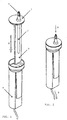
- FIGS. 1 and 2 a preferred embodiment of the present invention is illustrated in FIGS. 1 and 2 .
- the device is assembled in manufacture by inserting (see arrow X in Figure 1 ) the top (1), featuring an inlet passage (2) which may be fitted with a filter (not shown) at its lower outlet, and a dividing panel (3), into the base (4), the base being manufactured from a clear material (preferably a medical grade rigid plastic), and having a corresponding recess to accommodate the dividing panel.
- the finished assembly may be bonded by heat sealing, ultrasonic welding or solvent cementing.
- FIG. 2 shows the assembled flow meter for liquid flowing from a supply container (not shown) into the circulatory system of a patient (not shown).
- the liquid container is either a flexible bag or vented rigid container.
- the penetrant with liquid inlet (5) is inserted into the supply container (not shown) to define an inlet passage (2) for liquid flow (see arrow Y) from the supply container downwards under gravity, and regulated by an external flow control device (typically a manual 'roller clamp', positioned downstream of the device).
- This passage may be fitted with a filter (not shown) at its lower outlet in order to prevent particles in the liquid being deposited in the flow-resistant liquid passage ((6) in FIG. 6 ), which might affect the device reliability.
- the lower part of the inlet passage (2) is in communication with both an indicating chamber (9) and a flow-resistant liquid passage (6).
- the flow-resistant liquid passage (6) provides sufficient resistance to liquid flow such that liquid rises in the indicating chamber (9) to a height proportional to the flow rate.
- a scale of calibrated indices may be placed alongside the indicating chamber (9).
- the minimum width of the indicating chamber is sufficiently wide (>1mm, preferred width 1.5mm) to reduce the effects of capillary action, yet sufficiently narrow to ensure that the response of the liquid column quickly follows any flow changes made by the operator by the use of the external flow control device. This width is reliably maintained by the secure interference fit between the top component (1) and the base component (4).
- the insertion of the top component (1) with the dividing panel (3) into the base (4) forms the flow-resistant liquid passage (6) with a chamfered inlet, a 'U' shaped bend (7) and a chamfered outlet (8).
- the slight taper on the dividing panel (3) improves the interference fit necessary to form a sufficient seal, as well as serving as a draft angle to help the injection moulding process.
- the dimensions of the flow-resistant liquid passage are maintained reliably by this interference fit; the dividing panel (3) providing a seal against the corresponding recess in the base component (4) into which the flow-resistant liquid passage is moulded.
- liquid Upon exit from this outlet (8), liquid enters the exit chamber (11) formed by the base component (4) and top component (1) and flows out through the main outlet (12) (see arrow Z in Figure 2 ) which may accommodate a standard filter (not necessary if one is fitted to the inlet passage) into the length of tubing connecting the device to an intravenous cannula inserted into the patient.
- the liquid level in the indicating chamber (9) may rise above an overflow ((10) in FIG. 4 ), and thus liquid may flow into the exit chamber (11) formed by the base component (4) and top component (1), and then out through the main outlet (12).
- an overflow ((10) in FIG. 4 )
- liquid may flow into the exit chamber (11) formed by the base component (4) and top component (1), and then out through the main outlet (12).
- a readable scale from 0 - 250 ml/hr may be provided on the indicating chamber (9), but flow rates of 3000ml/hr or more (necessary during resuscitation attempts) may also be achieved by the device; the scale being unnecessary at such high flow rates.
- the overflow (10) may be so shaped as to produce drops as liquid flows into the exit chamber (11). Thus, if control of flow at rates greater than those measurable in the indicating chamber is required, drops may be counted as per the current method of measuring flow rate.
- the liquid contained in the full indicating chamber (9) flows through the flow-resistant liquid passage (6) into the exit chamber (11) formed by the base component (4) and the top component (1).
- the exit chamber (11) begins to fill with the remaining liquid flowing out of the indicating chamber (9).
- the outlet of the flow-resistant liquid passage (8) is positioned at sufficient height (greater than 20mm) above the main outlet (12) such that as the exit chamber (11) fills with the remaining liquid from the indicating chamber (9), the liquid height does not reach this outlet.
- the design of the present invention dictates that as liquid flows through the liquid inlet passage (2), flow-resistant liquid passage (6) and indicating chamber (9), no drops are formed. This avoids the problem of irregular drop size affecting the height of liquid in the indicating chamber, as well as any problems introduced by the need to break the surface tension of drops at low flow rates.
- a small float in the indicating chamber (9) rises and falls with the liquid level, facilitating the reading of flow rate.
- the float may provide greater visual contrast (e.g. bright colour).
- the overflow outlet (10) at the top of the indicating chamber (9) must be wide enough to allow liquid through, but narrow enough to prevent the indicating float exiting the indicating chamber (9) at high flow rates.
- the device herein described is intended to be used by itself in the usual infusion apparatus, it may also be used in series with other flow devices such as electrically driven pumps to monitor or set rate of flow.
Landscapes
- Health & Medical Sciences (AREA)
- Fluid Mechanics (AREA)
- Physics & Mathematics (AREA)
- Heart & Thoracic Surgery (AREA)
- Life Sciences & Earth Sciences (AREA)
- Engineering & Computer Science (AREA)
- Anesthesiology (AREA)
- Biomedical Technology (AREA)
- Veterinary Medicine (AREA)
- Hematology (AREA)
- Vascular Medicine (AREA)
- Animal Behavior & Ethology (AREA)
- General Health & Medical Sciences (AREA)
- Public Health (AREA)
- General Physics & Mathematics (AREA)
- Measuring Volume Flow (AREA)
- Infusion, Injection, And Reservoir Apparatuses (AREA)
Claims (15)
- Durchflussmesservorrichtung, umfassend:einen Flüssigkeitseinlass (5);einen Flüssigkeitsauslass (12);eine Einlasspassage (2), die ein oberes und ein unteres Ende hat und die an ihrem oberen Ende in Kommunikation mit dem Flüssigkeitseinlass (5) ist;eine Anzeigekammer (9), die ein unteres Ende hat in Kommunikation mit dem unteren Ende der Einlasspassage (2), wobei die Anzeigekammer (9) sich aufwärts von ihrem unteren Ende zu einem offenen oberen Ende erstreckt, wobei mindestens ein Teil der Anzeigekammer (9) lichtdurchlässig oder transparent ist, um die Höhe der Flüssigkeit in der Anzeigekammer (9) zu zeigen;eine Ausgangskammer (11), die in Kommunikation mit dem Flüssigkeitsauslass (12) ist; undeine flussresistente Flüssigkeitspassage (6), die sich zwischen dem unteren Ende der Einlasspassage (2) und der Ausgangskammer (11) erstreckt und in Kommunikation mit der Anzeigekammer (9);wobei die flussresistente Flüssigkeitspassage (6) einem Flüssigkeitsfluss einen größeren Widerstand bereitstellt, als sowohl die Einlasspassage (2) als auch die Anzeigekammer (9), wodurch Flüssigkeit von dem Flüssigkeitseinlass (5) durch die Einlasspassage (2) und durch die flussresistente Flüssigkeitspassage (6) in die Ausgangskammer (11) fließen kann und von da zu dem Flüssigkeitsauslass (12) und ebenso von der Einlasspassage (2) in die Anzeigekammer (9), wo sie eine Höhe erreicht, die in Übereinstimmung mit dem Fluss der Flüssigkeit durch die Einlasspassage (2) ist;dadurch gekennzeichnet, dass:die Vorrichtung in zwei Teilen hergestellt ist, wobei ein erster Teil den Flüssigkeitsauslass (12) und die Ausgangskammer (11) einschließt und wobei der zweite Teil den Flüssigkeitseinlass (5) und die Einlasspassage (2) einschließt und wobei die flussresistente Flüssigkeitspassage (6) und die Anzeigekammer (9) bereitgestellt sind zwischen dem ersten Teil und dem zweiten Teil; unddie flussresistente Flüssigkeitspassage (6) U-förmig ist und wobei der erste Teil eine geschlossene Bohrung einschließt und der zweite Teil eine Barriere einschließt, die in der Bohrung lokalisiert ist, um die Bohrung in separate Kanäle zu teilen, die zusammen die U-förmige flussresistente Flüssigkeitspassage (6) bilden.
- Vorrichtung nach Anspruch 1, wobei die Anzeigekammer (9) eine kalibrierte Skala einschließt, um ein Maß der Höhe der Flüssigkeit in der Anzeigekammer (9) bereitzustellen und dadurch ein Maß des Flusses von Flüssigkeit durch die Einlasspassage (2).
- Vorrichtung nach einem vorstehenden Anspruch, wobei die Länge der Einlasspassage (2) und ihre Kommunikation mit der Anzeigekammer (9) und mit der flussresistenten Flüssigkeitspassage (6) derartig ist, dass sich keine Tropfen bilden, wenn Flüssigkeit durch die Einlasspassage (2), die flussresistente Flüssigkeitspassage (6) und die Anzeigekammer (9) fließt.
- Vorrichtung nach einem vorstehenden Anspruch,
wobei das Auslassende (8) der flussresistenten Flüssigkeitspassage (6) oberhalb des Niveaus des Flüssigkeitsauslasses (12) positioniert ist; und
wobei das Volumen der Anzeigekammer (9) kleiner ist, als das Volumen der Ausgangskammer (11) unterhalb des Auslassendes der flussresistenten Flüssigkeitspassage (6), wodurch, falls das Volumen von Flüssigkeit, das in der vollen Anzeigekammer (9) enthalten ist, in die Ausgangskammer (11) fließt, das resultierende Flüssigkeitsniveau in der Ausgangskammer (11) kleiner ist, als die Höhe des Auslassendes der flussresistenten Flüssigkeitspassage (6) in der Ausgangskammer (11), sodass Flüssigkeit nicht zurück durch die flussresistente Flüssigkeitspassage (6) fließen kann, wenn Flüssigkeitsfluss durch den Flüssigkeitseinlass (5) gestoppt wird und die Flüssigkeitsniveaus ein Gleichgewicht erreichen. - Vorrichtung nach einem vorstehenden Anspruch, wobei die U-förmige flussresistente Flüssigkeitspassage (6) ein Auslassende und ein Einlassende hat, die ungefähr in derselben Höhe sind, wenn die Vorrichtung vertikal angeordnet ist, sodass die Flüssigkeit in der flussresistenten Flüssigkeitspassage (6) bleibt, wenn keine Flüssigkeit durch die Vorrichtung fließt, wodurch die flussresistente Flüssigkeitspassage (6) am Austrocknen gehindert wird.
- Vorrichtung nach Anspruch 5, wobei die Einlass- und Auslassenden der flussresistenten Flüssigkeitspassage (6) abgeschrägt sind, sodass Flüssigkeit da bleibt, wenn die Vorrichtung in Ruhe ist, wobei keine Flüssigkeit durch die Vorrichtung fließt.
- Vorrichtung nach einem vorstehenden Anspruch, wobei die Querschnittsfläche der Anzeigekammer (9) ausreichend schmal ist, um sicherzustellen, dass Flussratenänderungen, die durch einen Bediener eingestellt werden, in einer schnellen korrespondierenden Änderung in der Flüssigkeitshöhe resultieren, jedoch ausreichend weit, um die Effekte von Kapillarwirkung zu mildern.
- Vorrichtung nach einem vorstehenden Anspruch, wobei die Querschnittsfläche und -länge der flussresistenten Flüssigkeitspassage (6) dem Fluss ausreichenden Widerstand bereitstellen, um in einer merklichen Änderung von Flüssigkeitshöhe in der Anzeigekammer (9) zu resultieren, wenn die Flussrate durch die Vorrichtung 0 - 250 ml/Stunde ist.
- Vorrichtung nach einem vorstehenden Anspruch, wobei die Einlasspassage (2), die Anzeigekammer (9) und die flussresistente Flüssigkeitspassage (6) sich alle im Wesentlichen in der vertikalen Richtung erstrecken, wenn die Vorrichtung vertikal orientiert ist.
- Vorrichtung nach einem vorstehenden Anspruch, wobei die Einlasspassage (2), die Anzeigekammer (9) und die flussresistente Flüssigkeitspassage (6) den Fluss von Flüssigkeit erlauben, ohne zuzulassen, dass sich Tropfen während des Flusses bilden.
- Vorrichtung nach einem vorstehenden Anspruch, wobei der Überlauf (10) von der Anzeigekammer (9) so geformt sein kann, um Tropfen zu bilden, während Flüssigkeit in die Ausgangskammer (11) fließt, um Flussraten, höher als solche, die in der Anzeigekammer (9) gemessen werden, zu erlauben gemessen zu werden, unter Verwendung des gegenwärtigen Verfahrens des Tropfen Zählens.
- Vorrichtung nach einem vorstehenden Anspruch, wobei die Vorrichtung eine äußere Wand hat, die Teil des ersten Teils ist und wobei die Anzeigekammer (9) gebildet ist zwischen dem zweiten Teil und der äußeren Wand, wobei die äußere Wand optional aus einem lichtdurchlässigen oder transparenten Material hergestellt ist.
- Vorrichtung nach einem vorstehenden Anspruch, wobei die Anzeigekammer (9) einen sichtbaren Schwimmer enthält, um das Ablesen des Flüssigkeitsniveaus in der Anzeigekammer (9) und damit der Flüssigkeitsflussrate zu erleichtern.
- Vorrichtung nach einem vorstehenden Anspruch, wobei die Einlasspassage (2) mit einem Filter an ihrem unterem Auslass angepasst ist und/oder wobei der Auslass (12) einen Filter beherbergt.
- Vorrichtung nach einem vorstehenden Anspruch, wobei der erste Teil (4) in den zweiten Teil (1) eingefügt ist; und, optional oder vorzugsweise, wobei jeder Teil ein zweiteiliges Formteil ist.
Applications Claiming Priority (2)
| Application Number | Priority Date | Filing Date | Title |
|---|---|---|---|
| GBGB1506771.3A GB201506771D0 (en) | 2015-04-21 | 2015-04-21 | Flow meter for intravenous liquids |
| PCT/GB2015/000233 WO2016170296A1 (en) | 2015-04-21 | 2015-08-07 | Flow meter for intravenous liquids |
Publications (2)
| Publication Number | Publication Date |
|---|---|
| EP3294379A1 EP3294379A1 (de) | 2018-03-21 |
| EP3294379B1 true EP3294379B1 (de) | 2019-04-03 |
Family
ID=53298936
Family Applications (1)
| Application Number | Title | Priority Date | Filing Date |
|---|---|---|---|
| EP15763640.8A Active EP3294379B1 (de) | 2015-04-21 | 2015-08-07 | Durchflussmesser für intravenöse flüssigkeiten |
Country Status (7)
| Country | Link |
|---|---|
| US (1) | US10525198B2 (de) |
| EP (1) | EP3294379B1 (de) |
| JP (1) | JP6721671B2 (de) |
| CN (1) | CN107530492B (de) |
| BR (1) | BR112017022629A2 (de) |
| GB (1) | GB201506771D0 (de) |
| WO (1) | WO2016170296A1 (de) |
Cited By (2)
| Publication number | Priority date | Publication date | Assignee | Title |
|---|---|---|---|---|
| WO2020254814A1 (en) | 2019-06-18 | 2020-12-24 | Jonathan Charles Devlin West | Flow metering insert and/or device |
| WO2025120330A1 (en) | 2023-12-08 | 2025-06-12 | Jonathan Charles Devlin West | Flow metering insert for a drip chamber |
Families Citing this family (1)
| Publication number | Priority date | Publication date | Assignee | Title |
|---|---|---|---|---|
| CN115441241A (zh) * | 2022-08-31 | 2022-12-06 | 上海航安机场设备有限公司 | 一种刚性本体灌注式电缆连接头、电缆连接装置及安装方法 |
Family Cites Families (10)
| Publication number | Priority date | Publication date | Assignee | Title |
|---|---|---|---|---|
| US2479786A (en) | 1945-10-24 | 1949-08-23 | Daniel S Stevens | Liquid flow gauge |
| SE318123B (de) * | 1967-12-21 | 1969-12-01 | Gambro Ab | |
| US3587313A (en) | 1969-01-30 | 1971-06-28 | I V Ometer Inc | Flow meter for parenteral solutions |
| US4136692A (en) * | 1976-02-19 | 1979-01-30 | Michael Goldowsky | Flow meter administration device |
| AU2229977A (en) * | 1976-02-19 | 1978-08-24 | Cutter Lab | Flow meter administration device |
| US4291693A (en) * | 1979-11-13 | 1981-09-29 | Sorenson Research Company, Inc. | Fluid metering device |
| US4523464A (en) * | 1983-10-13 | 1985-06-18 | The Dow Chemical Company | Flowmeter with no moving parts |
| DE4419369A1 (de) * | 1993-06-07 | 1994-12-22 | Dieter Dr Goehmann | Infusionsbesteck |
| US5352213A (en) | 1993-11-16 | 1994-10-04 | Woodard Robert W | Intravenous fluid flow monitor |
| EP2854898B1 (de) * | 2012-05-31 | 2019-07-10 | SHL Medical AG | Vorrichtung zur medikamentenverabreichung mit verzögerungsfeedbackmechanismus |
-
2015
- 2015-04-21 GB GBGB1506771.3A patent/GB201506771D0/en not_active Ceased
- 2015-08-07 WO PCT/GB2015/000233 patent/WO2016170296A1/en not_active Ceased
- 2015-08-07 CN CN201580079029.6A patent/CN107530492B/zh active Active
- 2015-08-07 EP EP15763640.8A patent/EP3294379B1/de active Active
- 2015-08-07 US US15/568,049 patent/US10525198B2/en active Active
- 2015-08-07 JP JP2018506490A patent/JP6721671B2/ja active Active
- 2015-08-07 BR BR112017022629-4A patent/BR112017022629A2/en not_active Application Discontinuation
Non-Patent Citations (1)
| Title |
|---|
| None * |
Cited By (3)
| Publication number | Priority date | Publication date | Assignee | Title |
|---|---|---|---|---|
| WO2020254814A1 (en) | 2019-06-18 | 2020-12-24 | Jonathan Charles Devlin West | Flow metering insert and/or device |
| US12691219B2 (en) | 2019-06-18 | 2026-07-28 | Jonathan Charles Devlin West | Flow metering insert and/or device |
| WO2025120330A1 (en) | 2023-12-08 | 2025-06-12 | Jonathan Charles Devlin West | Flow metering insert for a drip chamber |
Also Published As
| Publication number | Publication date |
|---|---|
| WO2016170296A1 (en) | 2016-10-27 |
| US10525198B2 (en) | 2020-01-07 |
| EP3294379A1 (de) | 2018-03-21 |
| CN107530492B (zh) | 2020-07-10 |
| CN107530492A (zh) | 2018-01-02 |
| JP6721671B2 (ja) | 2020-07-15 |
| US20180117247A1 (en) | 2018-05-03 |
| GB201506771D0 (en) | 2015-06-03 |
| BR112017022629A2 (en) | 2018-07-10 |
| JP2018515791A (ja) | 2018-06-14 |
Similar Documents
| Publication | Publication Date | Title |
|---|---|---|
| US8448523B2 (en) | Device and method for determining at least one flow parameter | |
| US4136692A (en) | Flow meter administration device | |
| US3587313A (en) | Flow meter for parenteral solutions | |
| EP2781229B1 (de) | Vorrichtung zur einstellung einer linearen strömungsrate für infusionen | |
| KR101487754B1 (ko) | 수액유량조절기 | |
| US7361155B2 (en) | Compensating liquid delivery system and method | |
| US4432762A (en) | Volumetric drop detector | |
| US10525198B2 (en) | Flow meter for intravenous liquids | |
| KR20090010019A (ko) | 유량 제어식 투여세트 | |
| JP7325134B2 (ja) | 流量計量インサートおよび/または装置 | |
| US4340050A (en) | Medical fluid flow rate indicating/controlling device | |
| KR101952322B1 (ko) | 수액세트용 유량조절장치 | |
| US2479786A (en) | Liquid flow gauge | |
| EP3576812B1 (de) | System und verfahren zur überwachung des injektionsstellendrucks | |
| US4291693A (en) | Fluid metering device | |
| US8201461B2 (en) | Apparatus for measuring volumetric or mass fluid flow | |
| WO2025120330A1 (en) | Flow metering insert for a drip chamber | |
| Schnell | Measurement of flow in infusion systems | |
| RU2176526C1 (ru) | Устройство для дозированной капельной инфузии | |
| WO2005084125A2 (en) | Liquid flow monitoring apparatus | |
| RU16904U1 (ru) | Устройство для дозированной капельной инфузии | |
| GB2102566A (en) | Volumetric drop detector |
Legal Events
| Date | Code | Title | Description |
|---|---|---|---|
| STAA | Information on the status of an ep patent application or granted ep patent |
Free format text: STATUS: THE INTERNATIONAL PUBLICATION HAS BEEN MADE |
|
| PUAI | Public reference made under article 153(3) epc to a published international application that has entered the european phase |
Free format text: ORIGINAL CODE: 0009012 |
|
| STAA | Information on the status of an ep patent application or granted ep patent |
Free format text: STATUS: REQUEST FOR EXAMINATION WAS MADE |
|
| 17P | Request for examination filed |
Effective date: 20171121 |
|
| AK | Designated contracting states |
Kind code of ref document: A1 Designated state(s): AL AT BE BG CH CY CZ DE DK EE ES FI FR GB GR HR HU IE IS IT LI LT LU LV MC MK MT NL NO PL PT RO RS SE SI SK SM TR |
|
| AX | Request for extension of the european patent |
Extension state: BA ME |
|
| DAV | Request for validation of the european patent (deleted) | ||
| DAX | Request for extension of the european patent (deleted) | ||
| GRAP | Despatch of communication of intention to grant a patent |
Free format text: ORIGINAL CODE: EPIDOSNIGR1 |
|
| STAA | Information on the status of an ep patent application or granted ep patent |
Free format text: STATUS: GRANT OF PATENT IS INTENDED |
|
| INTG | Intention to grant announced |
Effective date: 20181016 |
|
| GRAS | Grant fee paid |
Free format text: ORIGINAL CODE: EPIDOSNIGR3 |
|
| GRAA | (expected) grant |
Free format text: ORIGINAL CODE: 0009210 |
|
| STAA | Information on the status of an ep patent application or granted ep patent |
Free format text: STATUS: THE PATENT HAS BEEN GRANTED |
|
| AK | Designated contracting states |
Kind code of ref document: B1 Designated state(s): AL AT BE BG CH CY CZ DE DK EE ES FI FR GB GR HR HU IE IS IT LI LT LU LV MC MK MT NL NO PL PT RO RS SE SI SK SM TR |
|
| REG | Reference to a national code |
Ref country code: GB Ref legal event code: FG4D |
|
| REG | Reference to a national code |
Ref country code: CH Ref legal event code: EP Ref country code: AT Ref legal event code: REF Ref document number: 1114951 Country of ref document: AT Kind code of ref document: T Effective date: 20190415 |
|
| REG | Reference to a national code |
Ref country code: DE Ref legal event code: R096 Ref document number: 602015027642 Country of ref document: DE |
|
| REG | Reference to a national code |
Ref country code: IE Ref legal event code: FG4D |
|
| REG | Reference to a national code |
Ref country code: NL Ref legal event code: MP Effective date: 20190403 |
|
| REG | Reference to a national code |
Ref country code: LT Ref legal event code: MG4D |
|
| REG | Reference to a national code |
Ref country code: AT Ref legal event code: MK05 Ref document number: 1114951 Country of ref document: AT Kind code of ref document: T Effective date: 20190403 |
|
| PG25 | Lapsed in a contracting state [announced via postgrant information from national office to epo] |
Ref country code: NL Free format text: LAPSE BECAUSE OF FAILURE TO SUBMIT A TRANSLATION OF THE DESCRIPTION OR TO PAY THE FEE WITHIN THE PRESCRIBED TIME-LIMIT Effective date: 20190403 |
|
| PG25 | Lapsed in a contracting state [announced via postgrant information from national office to epo] |
Ref country code: CZ Free format text: LAPSE BECAUSE OF FAILURE TO SUBMIT A TRANSLATION OF THE DESCRIPTION OR TO PAY THE FEE WITHIN THE PRESCRIBED TIME-LIMIT Effective date: 20190403 Ref country code: LT Free format text: LAPSE BECAUSE OF FAILURE TO SUBMIT A TRANSLATION OF THE DESCRIPTION OR TO PAY THE FEE WITHIN THE PRESCRIBED TIME-LIMIT Effective date: 20190403 Ref country code: HR Free format text: LAPSE BECAUSE OF FAILURE TO SUBMIT A TRANSLATION OF THE DESCRIPTION OR TO PAY THE FEE WITHIN THE PRESCRIBED TIME-LIMIT Effective date: 20190403 Ref country code: FI Free format text: LAPSE BECAUSE OF FAILURE TO SUBMIT A TRANSLATION OF THE DESCRIPTION OR TO PAY THE FEE WITHIN THE PRESCRIBED TIME-LIMIT Effective date: 20190403 Ref country code: NO Free format text: LAPSE BECAUSE OF FAILURE TO SUBMIT A TRANSLATION OF THE DESCRIPTION OR TO PAY THE FEE WITHIN THE PRESCRIBED TIME-LIMIT Effective date: 20190703 Ref country code: AL Free format text: LAPSE BECAUSE OF FAILURE TO SUBMIT A TRANSLATION OF THE DESCRIPTION OR TO PAY THE FEE WITHIN THE PRESCRIBED TIME-LIMIT Effective date: 20190403 Ref country code: PT Free format text: LAPSE BECAUSE OF FAILURE TO SUBMIT A TRANSLATION OF THE DESCRIPTION OR TO PAY THE FEE WITHIN THE PRESCRIBED TIME-LIMIT Effective date: 20190803 Ref country code: SE Free format text: LAPSE BECAUSE OF FAILURE TO SUBMIT A TRANSLATION OF THE DESCRIPTION OR TO PAY THE FEE WITHIN THE PRESCRIBED TIME-LIMIT Effective date: 20190403 |
|
| PG25 | Lapsed in a contracting state [announced via postgrant information from national office to epo] |
Ref country code: LV Free format text: LAPSE BECAUSE OF FAILURE TO SUBMIT A TRANSLATION OF THE DESCRIPTION OR TO PAY THE FEE WITHIN THE PRESCRIBED TIME-LIMIT Effective date: 20190403 Ref country code: RS Free format text: LAPSE BECAUSE OF FAILURE TO SUBMIT A TRANSLATION OF THE DESCRIPTION OR TO PAY THE FEE WITHIN THE PRESCRIBED TIME-LIMIT Effective date: 20190403 Ref country code: GR Free format text: LAPSE BECAUSE OF FAILURE TO SUBMIT A TRANSLATION OF THE DESCRIPTION OR TO PAY THE FEE WITHIN THE PRESCRIBED TIME-LIMIT Effective date: 20190704 Ref country code: PL Free format text: LAPSE BECAUSE OF FAILURE TO SUBMIT A TRANSLATION OF THE DESCRIPTION OR TO PAY THE FEE WITHIN THE PRESCRIBED TIME-LIMIT Effective date: 20190403 Ref country code: BG Free format text: LAPSE BECAUSE OF FAILURE TO SUBMIT A TRANSLATION OF THE DESCRIPTION OR TO PAY THE FEE WITHIN THE PRESCRIBED TIME-LIMIT Effective date: 20190703 |
|
| PG25 | Lapsed in a contracting state [announced via postgrant information from national office to epo] |
Ref country code: IS Free format text: LAPSE BECAUSE OF FAILURE TO SUBMIT A TRANSLATION OF THE DESCRIPTION OR TO PAY THE FEE WITHIN THE PRESCRIBED TIME-LIMIT Effective date: 20190803 Ref country code: AT Free format text: LAPSE BECAUSE OF FAILURE TO SUBMIT A TRANSLATION OF THE DESCRIPTION OR TO PAY THE FEE WITHIN THE PRESCRIBED TIME-LIMIT Effective date: 20190403 |
|
| REG | Reference to a national code |
Ref country code: DE Ref legal event code: R097 Ref document number: 602015027642 Country of ref document: DE |
|
| PG25 | Lapsed in a contracting state [announced via postgrant information from national office to epo] |
Ref country code: RO Free format text: LAPSE BECAUSE OF FAILURE TO SUBMIT A TRANSLATION OF THE DESCRIPTION OR TO PAY THE FEE WITHIN THE PRESCRIBED TIME-LIMIT Effective date: 20190403 Ref country code: EE Free format text: LAPSE BECAUSE OF FAILURE TO SUBMIT A TRANSLATION OF THE DESCRIPTION OR TO PAY THE FEE WITHIN THE PRESCRIBED TIME-LIMIT Effective date: 20190403 Ref country code: SK Free format text: LAPSE BECAUSE OF FAILURE TO SUBMIT A TRANSLATION OF THE DESCRIPTION OR TO PAY THE FEE WITHIN THE PRESCRIBED TIME-LIMIT Effective date: 20190403 Ref country code: DK Free format text: LAPSE BECAUSE OF FAILURE TO SUBMIT A TRANSLATION OF THE DESCRIPTION OR TO PAY THE FEE WITHIN THE PRESCRIBED TIME-LIMIT Effective date: 20190403 |
|
| PLBE | No opposition filed within time limit |
Free format text: ORIGINAL CODE: 0009261 |
|
| STAA | Information on the status of an ep patent application or granted ep patent |
Free format text: STATUS: NO OPPOSITION FILED WITHIN TIME LIMIT |
|
| PG25 | Lapsed in a contracting state [announced via postgrant information from national office to epo] |
Ref country code: SM Free format text: LAPSE BECAUSE OF FAILURE TO SUBMIT A TRANSLATION OF THE DESCRIPTION OR TO PAY THE FEE WITHIN THE PRESCRIBED TIME-LIMIT Effective date: 20190403 Ref country code: IT Free format text: LAPSE BECAUSE OF FAILURE TO SUBMIT A TRANSLATION OF THE DESCRIPTION OR TO PAY THE FEE WITHIN THE PRESCRIBED TIME-LIMIT Effective date: 20190403 |
|
| 26N | No opposition filed |
Effective date: 20200106 |
|
| PG25 | Lapsed in a contracting state [announced via postgrant information from national office to epo] |
Ref country code: TR Free format text: LAPSE BECAUSE OF FAILURE TO SUBMIT A TRANSLATION OF THE DESCRIPTION OR TO PAY THE FEE WITHIN THE PRESCRIBED TIME-LIMIT Effective date: 20190403 |
|
| PG25 | Lapsed in a contracting state [announced via postgrant information from national office to epo] |
Ref country code: CH Free format text: LAPSE BECAUSE OF NON-PAYMENT OF DUE FEES Effective date: 20190831 Ref country code: MC Free format text: LAPSE BECAUSE OF FAILURE TO SUBMIT A TRANSLATION OF THE DESCRIPTION OR TO PAY THE FEE WITHIN THE PRESCRIBED TIME-LIMIT Effective date: 20190403 Ref country code: LU Free format text: LAPSE BECAUSE OF NON-PAYMENT OF DUE FEES Effective date: 20190807 Ref country code: LI Free format text: LAPSE BECAUSE OF NON-PAYMENT OF DUE FEES Effective date: 20190831 Ref country code: SI Free format text: LAPSE BECAUSE OF FAILURE TO SUBMIT A TRANSLATION OF THE DESCRIPTION OR TO PAY THE FEE WITHIN THE PRESCRIBED TIME-LIMIT Effective date: 20190403 |
|
| REG | Reference to a national code |
Ref country code: BE Ref legal event code: MM Effective date: 20190831 |
|
| PG25 | Lapsed in a contracting state [announced via postgrant information from national office to epo] |
Ref country code: IE Free format text: LAPSE BECAUSE OF NON-PAYMENT OF DUE FEES Effective date: 20190807 |
|
| PG25 | Lapsed in a contracting state [announced via postgrant information from national office to epo] |
Ref country code: BE Free format text: LAPSE BECAUSE OF NON-PAYMENT OF DUE FEES Effective date: 20190831 |
|
| PG25 | Lapsed in a contracting state [announced via postgrant information from national office to epo] |
Ref country code: ES Free format text: LAPSE BECAUSE OF FAILURE TO SUBMIT A TRANSLATION OF THE DESCRIPTION OR TO PAY THE FEE WITHIN THE PRESCRIBED TIME-LIMIT Effective date: 20190403 |
|
| PG25 | Lapsed in a contracting state [announced via postgrant information from national office to epo] |
Ref country code: CY Free format text: LAPSE BECAUSE OF FAILURE TO SUBMIT A TRANSLATION OF THE DESCRIPTION OR TO PAY THE FEE WITHIN THE PRESCRIBED TIME-LIMIT Effective date: 20190403 |
|
| PG25 | Lapsed in a contracting state [announced via postgrant information from national office to epo] |
Ref country code: MT Free format text: LAPSE BECAUSE OF FAILURE TO SUBMIT A TRANSLATION OF THE DESCRIPTION OR TO PAY THE FEE WITHIN THE PRESCRIBED TIME-LIMIT Effective date: 20190403 Ref country code: HU Free format text: LAPSE BECAUSE OF FAILURE TO SUBMIT A TRANSLATION OF THE DESCRIPTION OR TO PAY THE FEE WITHIN THE PRESCRIBED TIME-LIMIT; INVALID AB INITIO Effective date: 20150807 |
|
| PG25 | Lapsed in a contracting state [announced via postgrant information from national office to epo] |
Ref country code: MK Free format text: LAPSE BECAUSE OF FAILURE TO SUBMIT A TRANSLATION OF THE DESCRIPTION OR TO PAY THE FEE WITHIN THE PRESCRIBED TIME-LIMIT Effective date: 20190403 |
|
| P01 | Opt-out of the competence of the unified patent court (upc) registered |
Effective date: 20230420 |
|
| PGFP | Annual fee paid to national office [announced via postgrant information from national office to epo] |
Ref country code: DE Payment date: 20250827 Year of fee payment: 11 |
|
| PGFP | Annual fee paid to national office [announced via postgrant information from national office to epo] |
Ref country code: FR Payment date: 20250825 Year of fee payment: 11 |
|
| PGFP | Annual fee paid to national office [announced via postgrant information from national office to epo] |
Ref country code: GB Payment date: 20260602 Year of fee payment: 12 |