EP3294233B1 - Off-load high leg-foot brace - Google Patents
Off-load high leg-foot brace Download PDFInfo
- Publication number
- EP3294233B1 EP3294233B1 EP15819840.8A EP15819840A EP3294233B1 EP 3294233 B1 EP3294233 B1 EP 3294233B1 EP 15819840 A EP15819840 A EP 15819840A EP 3294233 B1 EP3294233 B1 EP 3294233B1
- Authority
- EP
- European Patent Office
- Prior art keywords
- brace
- back portion
- sole
- base plate
- patient
- Prior art date
- Legal status (The legal status is an assumption and is not a legal conclusion. Google has not performed a legal analysis and makes no representation as to the accuracy of the status listed.)
- Active
Links
Images


Classifications
-
- A—HUMAN NECESSITIES
- A61—MEDICAL OR VETERINARY SCIENCE; HYGIENE
- A61F—FILTERS IMPLANTABLE INTO BLOOD VESSELS; PROSTHESES; DEVICES PROVIDING PATENCY TO, OR PREVENTING COLLAPSING OF, TUBULAR STRUCTURES OF THE BODY, e.g. STENTS; ORTHOPAEDIC, NURSING OR CONTRACEPTIVE DEVICES; FOMENTATION; TREATMENT OR PROTECTION OF EYES OR EARS; BANDAGES, DRESSINGS OR ABSORBENT PADS; FIRST-AID KITS
- A61F5/00—Orthopaedic methods or devices for non-surgical treatment of bones or joints; Nursing devices ; Anti-rape devices
- A61F5/01—Orthopaedic devices, e.g. long-term immobilising or pressure directing devices for treating broken or deformed bones such as splints, casts or braces
- A61F5/0102—Orthopaedic devices, e.g. long-term immobilising or pressure directing devices for treating broken or deformed bones such as splints, casts or braces specially adapted for correcting deformities of the limbs or for supporting them; Ortheses, e.g. with articulations
- A61F5/0104—Orthopaedic devices, e.g. long-term immobilising or pressure directing devices for treating broken or deformed bones such as splints, casts or braces specially adapted for correcting deformities of the limbs or for supporting them; Ortheses, e.g. with articulations without articulation
- A61F5/0111—Orthopaedic devices, e.g. long-term immobilising or pressure directing devices for treating broken or deformed bones such as splints, casts or braces specially adapted for correcting deformities of the limbs or for supporting them; Ortheses, e.g. with articulations without articulation for the feet or ankles
-
- A—HUMAN NECESSITIES
- A61—MEDICAL OR VETERINARY SCIENCE; HYGIENE
- A61F—FILTERS IMPLANTABLE INTO BLOOD VESSELS; PROSTHESES; DEVICES PROVIDING PATENCY TO, OR PREVENTING COLLAPSING OF, TUBULAR STRUCTURES OF THE BODY, e.g. STENTS; ORTHOPAEDIC, NURSING OR CONTRACEPTIVE DEVICES; FOMENTATION; TREATMENT OR PROTECTION OF EYES OR EARS; BANDAGES, DRESSINGS OR ABSORBENT PADS; FIRST-AID KITS
- A61F5/00—Orthopaedic methods or devices for non-surgical treatment of bones or joints; Nursing devices ; Anti-rape devices
- A61F5/01—Orthopaedic devices, e.g. long-term immobilising or pressure directing devices for treating broken or deformed bones such as splints, casts or braces
- A61F5/0195—Shoe-like orthopaedic devices for protecting the feet against injuries after operations
-
- A—HUMAN NECESSITIES
- A43—FOOTWEAR
- A43B—CHARACTERISTIC FEATURES OF FOOTWEAR; PARTS OF FOOTWEAR
- A43B7/00—Footwear with health or hygienic arrangements
- A43B7/14—Footwear with health or hygienic arrangements with foot-supporting parts
- A43B7/1405—Footwear with health or hygienic arrangements with foot-supporting parts with pads or holes on one or more locations, or having an anatomical or curved form
- A43B7/1455—Footwear with health or hygienic arrangements with foot-supporting parts with pads or holes on one or more locations, or having an anatomical or curved form with special properties
- A43B7/1464—Footwear with health or hygienic arrangements with foot-supporting parts with pads or holes on one or more locations, or having an anatomical or curved form with special properties with adjustable pads to allow custom fit
-
- A—HUMAN NECESSITIES
- A43—FOOTWEAR
- A43B—CHARACTERISTIC FEATURES OF FOOTWEAR; PARTS OF FOOTWEAR
- A43B7/00—Footwear with health or hygienic arrangements
- A43B7/14—Footwear with health or hygienic arrangements with foot-supporting parts
- A43B7/22—Footwear with health or hygienic arrangements with foot-supporting parts with fixed flat-foot insertions, metatarsal supports, ankle flaps or the like
Definitions
- the present disclosure relates to an off-load high leg-foot brace capable of immobilizing the foot and the leg of a patient, either completely or partially.
- Orthopedic braces can be found on the market, comprising a suitably shaped sole in order to allow the patient wearing said orthopedic braces to walk without stressing the injured foot.
- US 8,230,619 discloses an orthopedic footwear comprising an ambidextrous bottom sole comprising a large groove that is open on top and extends for almost the entire length and width of the sole. Said groove is intended to receive a rigid insert having a function of avoiding flexing and torsion in the plantar area of the foot both in a static and dynamic phase.
- the rigid insert has an upper surface intended to be faced towards the plantar area of the patient's foot, which is perfectly smooth and flat.
- the orthopedic footwear described in document US 8,230,619 also comprises an upper directly and firmly connected to the bottom sole and a soft insole disposed on the rigid insert.
- the soft insole is of modular type and is composed of three interchangeable modules having different elasticity.
- the upper padding has a negative effect on deambulation and is hardly accepted by the patient.
- portion of the upper disposed in correspondence of the portion of the foot comprised between the heel and the calcaneus must be constantly inclined by an angle of 90° with respect to the upper flat surface of the rigid insert so that the patient can deambulate comfortably while keeping the foot in its correct position.
- the upper and the shape of the bottom sole are designed from time to time according to the specific therapy and/or pathology of the patient's foot; in view of the above, according to the patient's therapy and/or pathology, it is necessary to purchase a specific model of orthopedic footwear.
- US 5 425 701 A discloses a brace comprising a bottom comprising a sole, a rigid body comprising a base plate, a monolithic upper removably connected to the rigid body, and an intermediate sole.
- the purpose of the present invention is to remedy the aforementioned drawbacks of the prior art by disclosing an off-load high leg-foot brace that, in spite of being produced in a standard version, can be modified and customized during use according to the patient's foot and therapy/pathology.
- the off-load high leg-foot brace of the invention comprises the features of claim 1.
- brace according to the present invention comprising an upper that, in case of need, can be easily and rapidly replaced with another upper according to the patient's requirements.
- the upper of the brace of the invention is made of a material that can be thermoformed and cut according to the shape of the foot and to the injuries of the patient, in order to perfectly adjust to the foot and the pathology of the patient's foot.
- the bottom which is composed of the aforementioned soft sole and stiffening plate, can be easily coupled and uncoupled with respect to the body of the brace of the invention in such manner that the patient can provide the brace with a suitable bottom from time to time according to his pathology and medical conditions, given the fact that, in spite of being always provided with the stiffening plate that is to be connected to the body, the bottom can be characterized by a sole with different softness level and a tread with a different curvilinear profile.
- brace of the invention is disclosed and generally indicated with reference numeral (1).
- the brace (1) comprises a bottom (F1) comprising a soft sole (2) and a stiffening plate (5) associated with the sole (2) and fixed on the sole (2).
- the sole (2) comprises a tread (21) intended to come in contact with the ground, and an internal surface (22) intended to be faced towards the patient's foot.
- front and back are referred respectively to the tip of the foot and the heel.
- the sole (2) is obtained from molding a soft thermoformable material, such as soft thermoplastic polyurethane or soft EVA.
- the stiffening plate (5) of the brace (1) is rigid and indeformable and has a shape similar to the internal surface (22) of the sole.
- the stiffening plate (5) comprises a lower surface (56) that is faced towards the sole (2), and an upper surface (57) that is faced upwards.
- the stiffening plate (5) is made of a rigid material, preferably rigid polyurethane.
- the stiffening plate (5) is glued to the sole (2) in order to increase the hardness and the rigidity of the surface whereon the patient's foot rests, and avoid flexing the sole (2) longitudinally during deambulation.
- the stiffening plate (5) has a perimeter edge (55) that protrudes upwards from the upper surface (57) of the stiffening plate, defining a cavity (50) that is open on top and extends for the entire length and width of the stiffening plate (5).
- the stiffening plate (5) is provided with two front slots (58) obtained in the front part on the perimeter edge (55) of the stiffening plate.
- the stiffening plate (5) is also provided with two back slots (52) obtained in peripheral position on the back of the upper surface (57) of the stiffening plate.
- the brace (1) comprises a body (6) made of rigid plastic, preferably rigid polypropylene.
- the body (6) is connected to the stiffening plate (5) by means of fit-in coupling.
- the body (6) is provided with an L-shaped configuration in cross-sectional view and comprises a base plate (60) and a back portion (61).
- the base plate (60) of the body has a shape that is substantially similar to the stiffening plate (5), is rigid and indeformable.
- the base plate (60) has a perfectly smooth planar upper surface (68), which is intended to be faced towards the plantar area of the patient's foot.
- the base plate (60) of the body (6) is fixed inside the cavity (50) of the stiffening plate (5) by means of fit-in coupling.
- the base plate (60) of the body comprises a perimeter edge (62) that protrudes on top from the base plate (60) in such manner to define an upper housing (63).
- the base plate (60) of the body comprises two elastically flexible back lateral tabs (65) ending with base teeth (65a) adapted to be fitted inside the back slots (52) obtained in the stiffening plate (5).
- the base plate (60) of the body also comprises two front teeth (66) that protrude frontally from the front part of the perimeter edge (62) of the base plate (60) of the body in order to be fitted in the front slots (58) of the stiffening plate (5).
- the back portion (61) of the body is curved in cross-section and is provided with an upper border (61a) and lateral borders (61b).
- the back portion (61) of the body (6) has a concavity intended to be faced towards the calcaneus and towards the back part of the patient's tibia.
- the brace (1) also comprises a flange (G) shaped as a square plate and connected to the back portion (61) of the body (6) by means of attachments (A) in order to protrude on the back of the body.
- the flange (G) is used for auxiliary treatments, for example to exercise a positive or negative pressure or to house a plantar pressure measuring device.
- Holes (66) are obtained on the perimeter edge (62) of the base portion (60) and in the back portion (61) of the body, in proximity to the lateral borders (61b) of said back portion (61) of the body.
- the brace (1) comprises a monolithic upper (7) molded from a soft thermoformable material, advantageously EVA.
- Said upper (7) has a net or grid structure with a dense series of through holes (76).
- the upper (7) comprises a back portion (70) and two lateral portions (71).
- the back portion (70) of the upper is curved in cross-section and has a concavity intended to be faced towards the patient's Achilles tendon, in such manner to surround the patient's calcaneus and the back part of the tibia.
- the back portion (70) of the upper has a concavity that corresponds to the concavity of the back portion (61) of the body.
- the lateral portions (71) of the upper (7) extend frontally from the back portion (70) in such manner to surround the internal side and the external side of the foot of the patient wearing the brace (1).
- the lateral portions (71) comprise a lower edge (72) and a plurality of wings (77) that protrude from the lower edge (72) of the lateral portions (71) towards the inside of the brace in order to be disposed on the upper surface (68) of the base plate (60) of the body, inside the upper housing (63) of the base plate (60) of the body.
- the brace (1) comprises a soft intermediate sole (3) intended to be disposed inside the upper housing (63) of the base plate (60) of the body, above the wings (77) of the upper that remain therefore tightened between the intermediate sole (3) in upper position and the base plate (60) of the body in lower position, thus preventing the upper (7) from being freely extracted from the body (6).
- said extraction can be easily and immediately made by simply removing the intermediate sole (3) from the upper (7).
- Said intermediate sole (3) comprises three arch supports (31, 32, 33) with different elastic properties.
- each arch support (31, 32, 33) of the intermediate sole (3) comprises:
- the modular intermediate sole (3) allows for fixing the upper (7) with respect to the base plate (60) of the body and, at the same time, modifying the hardness and elasticity of the surface that supports the patient's foot according to the patient's requirements.
- the upper (7) is connected to the body (6) by means of fit-in coupling.
- the back portion (70) of the upper comprises two projections (74) disposed on the back and intended to be engaged inside openings (64) obtained in the back portion (61) of the body (6), as shown in Figs. 1 and 2 .
- the upper (7) is fixed to the body (6) on the upper edge (61a) of the back portion (61) of the body.
- the upper (7) comprises an upper neck (7b) and a beak (7a), which is obtained on the neck (7b) of the upper and is intended to be coupled with the upper edge (61a) of the back portion (61) of the body in such manner to fix the upper (7) to the body (6).
- the brace (1) also comprises a tibial protection (8) with an L-shaped configuration in cross-section.
- the tibial protection (8) comprises a horizontal portion (80) intended to surround the dorsum of the patient's foot, and a vertical portion (81) intended to surround the patient's tibia.
- the horizontal portion (80) and the vertical portion (81) of the tibial protection have a curved shape in cross-section and are provided with a concavity intended to be respectively faced towards the dorsum of the patient's foot and towards the patient's tibia.
- the tibial protection (8) is made of the same material as the upper (7); in particular, the tibial protection (8) is a monolithic EVA piece with a net or grid structure, provided with a plurality of through holes (86).
- said tibial protection (8) allow the patient to cut said tibial protection in a suitable way to make it as comfortable as possible and associate it with the dorsum and the neck of the patient's foot.
- the brace (1) comprises fixing means to fix the tibial protection (8) on the upper (7).
- Said fixing means advantageously comprise wings (9) with a semi-elliptical shape.
- Each wing (9) has a through hole (90) and a slot (91).
- Each wing (9) is revolvingly connected to the body (6) by means of pins (92) that are fitted in the through hole (90) of the wing (9) and in one of the holes (66) of the body.
- Said fixing means also comprise straps (F) that are inserted and slide in the slots (91) of the wings to compress and hold the tibial protection (8) on the upper (7).
- the patient can choose the most comfortable fixing points for the straps (F) according to the position of the injuries on his foot.
- Fig. 5 shows a second embodiment of a body (106) that is basically identical to the body (6) as described above, except for the fact that it is provided with a slot (160) obtained on the heel of the patient's foot to make it easier for the patient to insert his foot in the brace in case of a pathology that requires the heel to remain free.
- the body (106) can be connected to the stiffening plate (5) and to the upper (7) of the brace (1) with the same means and in the same way as described above for the body (6).
- Fig. 6 shows a bottom (F2) using a sole (102) with a different profile compared to the one illustrated in Fig. 2 , it being understood that also the bottom (F2) is provided with the stiffening plate (5) that allows to couple the bottom (F2) with the body by means of fit-in coupling.
- the sole (102) has a tread (121) comprising a front portion (121a), a back portion (121b) and a central portion (121c), disposed in correspondence with the Chopart's line of the foot, between the front portion (121a) and the back portion (121b) of the tread (121) of the bottom (102).
- the front portion (121a) and the back portion (121b) of the tread (121) of the sole are convex and have the same concavity with the same preset radius of curvature.
- the central portion (121c) of the tread (121) of the sole (102) has a higher radius of curvature than the front portion (121a) and the back portion (121b); preferably, the central portion (121c) of the tread (121) of the sole (102) is flat.
- the central portion (121c) of the tread (121) of the sole (102) is very short compared to the front portion (121a) and the back portion (121b).
- the central portion (121c) of the tread (121) of the sole (102) has a length (L) lower than 15 mm, preferably comprised between 8 mm and 12 mm.
- the fact that the central portion (121c) of the tread (121) of the sole has a reduced length makes the brace unstable when the central portion (121c) of the tread (121) of the sole rests on the ground. Consequently, the deambulation of a patient wearing the brace (1) with the sole (102) implies a rolling motion of the sole (102) on the ground.
- the rolling motion provides for one of portions (121a, 121b, 121c) of the tread (121) of the sole to roll continuously and progressively on the ground.
- the progressive rolling motion of the sole (102) of the brace (1) allows for perfectly distributing the patient's weight on the entire surface of the sole (102) and avoids stress and trauma on the patient's foot.
Landscapes
- Health & Medical Sciences (AREA)
- Nursing (AREA)
- Orthopedic Medicine & Surgery (AREA)
- Engineering & Computer Science (AREA)
- Biomedical Technology (AREA)
- Heart & Thoracic Surgery (AREA)
- Vascular Medicine (AREA)
- Life Sciences & Earth Sciences (AREA)
- Animal Behavior & Ethology (AREA)
- General Health & Medical Sciences (AREA)
- Public Health (AREA)
- Veterinary Medicine (AREA)
- Orthopedics, Nursing, And Contraception (AREA)
- Footwear And Its Accessory, Manufacturing Method And Apparatuses (AREA)
- Professional, Industrial, Or Sporting Protective Garments (AREA)
Description
- The present disclosure relates to an off-load high leg-foot brace capable of immobilizing the foot and the leg of a patient, either completely or partially.
- Orthopedic braces can be found on the market, comprising a suitably shaped sole in order to allow the patient wearing said orthopedic braces to walk without stressing the injured foot.
-
US 8,230,619 discloses an orthopedic footwear comprising an ambidextrous bottom sole comprising a large groove that is open on top and extends for almost the entire length and width of the sole. Said groove is intended to receive a rigid insert having a function of avoiding flexing and torsion in the plantar area of the foot both in a static and dynamic phase. - The rigid insert has an upper surface intended to be faced towards the plantar area of the patient's foot, which is perfectly smooth and flat.
- The orthopedic footwear described in document
US 8,230,619 also comprises an upper directly and firmly connected to the bottom sole and a soft insole disposed on the rigid insert. The soft insole is of modular type and is composed of three interchangeable modules having different elasticity. - In spite of the aforementioned advantages, the use of similar orthopedic footwear is impaired by the fact that, during deambulation, the portion of the upper disposed in correspondence of the portion of the foot comprised between the heel and the calcaneus tends to bend with consequent discomfort for the patient.
- In said orthopedic footwear of the prior art, the upper padding has a negative effect on deambulation and is hardly accepted by the patient.
- It must be noted that the portion of the upper disposed in correspondence of the portion of the foot comprised between the heel and the calcaneus must be constantly inclined by an angle of 90° with respect to the upper flat surface of the rigid insert so that the patient can deambulate comfortably while keeping the foot in its correct position.
- In the orthopedic footwear of the prior art, the upper and the shape of the bottom sole are designed from time to time according to the specific therapy and/or pathology of the patient's foot; in view of the above, according to the patient's therapy and/or pathology, it is necessary to purchase a specific model of orthopedic footwear.
-
US 5 425 701 A discloses a brace comprising a bottom comprising a sole, a rigid body comprising a base plate, a monolithic upper removably connected to the rigid body, and an intermediate sole. - The purpose of the present invention is to remedy the aforementioned drawbacks of the prior art by disclosing an off-load high leg-foot brace that, in spite of being produced in a standard version, can be modified and customized during use according to the patient's foot and therapy/pathology.
- The off-load high leg-foot brace of the invention comprises the features of
claim 1. - The advantages of the brace according to the present invention are evident, it comprising an upper that, in case of need, can be easily and rapidly replaced with another upper according to the patient's requirements.
- Moreover, the upper of the brace of the invention is made of a material that can be thermoformed and cut according to the shape of the foot and to the injuries of the patient, in order to perfectly adjust to the foot and the pathology of the patient's foot.
- It should not be forgotten that also the bottom, which is composed of the aforementioned soft sole and stiffening plate, can be easily coupled and uncoupled with respect to the body of the brace of the invention in such manner that the patient can provide the brace with a suitable bottom from time to time according to his pathology and medical conditions, given the fact that, in spite of being always provided with the stiffening plate that is to be connected to the body, the bottom can be characterized by a sole with different softness level and a tread with a different curvilinear profile.
- Preferred embodiments of the invention are described in the dependent claims.
- For purpose of clarity the description of the brace according to the present invention continues with reference to the attached drawings, which are intended for purposes of illustration only, and not in a limiting sense, wherein:
-
Fig. 1 is an exploded axonometric view of the parts of the brace according to the invention; -
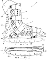
Fig. 2 is a side view of the brace of the invention, in assembled condition; -
Fig. 3 is an axonometric view of the brace of the invention, in assembled condition; -
Fig. 4 is a cross-sectional view of the soft intermediate sole of the brace of the invention; -
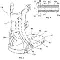
Fig. 5 is an axonometric view of a second embodiment of the body of the brace according to the invention; - Fig. 6 is a side view of the bottom of the brace according to the invention, wherein the sole in shown in a second embodiment.
- With reference to the attached figures, the brace of the invention is disclosed and generally indicated with reference numeral (1).
- With special reference to
Figs. 1 and2 , the brace (1) comprises a bottom (F1) comprising a soft sole (2) and a stiffening plate (5) associated with the sole (2) and fixed on the sole (2). - The sole (2) comprises a tread (21) intended to come in contact with the ground, and an internal surface (22) intended to be faced towards the patient's foot.
- In the description below, the terms "front" and "back" are referred respectively to the tip of the foot and the heel.
- The sole (2) is obtained from molding a soft thermoformable material, such as soft thermoplastic polyurethane or soft EVA.
- With reference to
Figs. 2 and3 , the stiffening plate (5) of the brace (1) is rigid and indeformable and has a shape similar to the internal surface (22) of the sole. The stiffening plate (5) comprises a lower surface (56) that is faced towards the sole (2), and an upper surface (57) that is faced upwards. The stiffening plate (5) is made of a rigid material, preferably rigid polyurethane. - The stiffening plate (5) is glued to the sole (2) in order to increase the hardness and the rigidity of the surface whereon the patient's foot rests, and avoid flexing the sole (2) longitudinally during deambulation.
- The stiffening plate (5) has a perimeter edge (55) that protrudes upwards from the upper surface (57) of the stiffening plate, defining a cavity (50) that is open on top and extends for the entire length and width of the stiffening plate (5).
- With reference to
Fig. 1 , the stiffening plate (5) is provided with two front slots (58) obtained in the front part on the perimeter edge (55) of the stiffening plate. - The stiffening plate (5) is also provided with two back slots (52) obtained in peripheral position on the back of the upper surface (57) of the stiffening plate.
- The brace (1) comprises a body (6) made of rigid plastic, preferably rigid polypropylene. The body (6) is connected to the stiffening plate (5) by means of fit-in coupling.
- The body (6) is provided with an L-shaped configuration in cross-sectional view and comprises a base plate (60) and a back portion (61).
- The base plate (60) of the body has a shape that is substantially similar to the stiffening plate (5), is rigid and indeformable. The base plate (60) has a perfectly smooth planar upper surface (68), which is intended to be faced towards the plantar area of the patient's foot.
- The base plate (60) of the body (6) is fixed inside the cavity (50) of the stiffening plate (5) by means of fit-in coupling.
- With reference to
Fig. 2 , the base plate (60) of the body comprises a perimeter edge (62) that protrudes on top from the base plate (60) in such manner to define an upper housing (63). - The base plate (60) of the body comprises two elastically flexible back lateral tabs (65) ending with base teeth (65a) adapted to be fitted inside the back slots (52) obtained in the stiffening plate (5). The base plate (60) of the body also comprises two front teeth (66) that protrude frontally from the front part of the perimeter edge (62) of the base plate (60) of the body in order to be fitted in the front slots (58) of the stiffening plate (5).
- The back portion (61) of the body is curved in cross-section and is provided with an upper border (61a) and lateral borders (61b). The back portion (61) of the body (6) has a concavity intended to be faced towards the calcaneus and towards the back part of the patient's tibia.
- The brace (1) also comprises a flange (G) shaped as a square plate and connected to the back portion (61) of the body (6) by means of attachments (A) in order to protrude on the back of the body. The flange (G) is used for auxiliary treatments, for example to exercise a positive or negative pressure or to house a plantar pressure measuring device.
- Holes (66) are obtained on the perimeter edge (62) of the base portion (60) and in the back portion (61) of the body, in proximity to the lateral borders (61b) of said back portion (61) of the body.
- The brace (1) comprises a monolithic upper (7) molded from a soft thermoformable material, advantageously EVA. Said upper (7) has a net or grid structure with a dense series of through holes (76).
- The upper (7) comprises a back portion (70) and two lateral portions (71).
- The back portion (70) of the upper is curved in cross-section and has a concavity intended to be faced towards the patient's Achilles tendon, in such manner to surround the patient's calcaneus and the back part of the tibia.
- In particular, the back portion (70) of the upper has a concavity that corresponds to the concavity of the back portion (61) of the body.
- The lateral portions (71) of the upper (7) extend frontally from the back portion (70) in such manner to surround the internal side and the external side of the foot of the patient wearing the brace (1). The lateral portions (71) comprise a lower edge (72) and a plurality of wings (77) that protrude from the lower edge (72) of the lateral portions (71) towards the inside of the brace in order to be disposed on the upper surface (68) of the base plate (60) of the body, inside the upper housing (63) of the base plate (60) of the body.
- The brace (1) comprises a soft intermediate sole (3) intended to be disposed inside the upper housing (63) of the base plate (60) of the body, above the wings (77) of the upper that remain therefore tightened between the intermediate sole (3) in upper position and the base plate (60) of the body in lower position, thus preventing the upper (7) from being freely extracted from the body (6). Evidently, said extraction can be easily and immediately made by simply removing the intermediate sole (3) from the upper (7).
- Said intermediate sole (3) comprises three arch supports (31, 32, 33) with different elastic properties.
- With reference to
Fig. 5 , each arch support (31, 32, 33) of the intermediate sole (3) comprises: - a front portion (31a, 32a, 33a);
- a back portion (31b, 32b, 33b); and
- a central portion (31c, 32c, 33c).
- The modular intermediate sole (3) allows for fixing the upper (7) with respect to the base plate (60) of the body and, at the same time, modifying the hardness and elasticity of the surface that supports the patient's foot according to the patient's requirements.
- The upper (7) is connected to the body (6) by means of fit-in coupling. In particular, the back portion (70) of the upper comprises two projections (74) disposed on the back and intended to be engaged inside openings (64) obtained in the back portion (61) of the body (6), as shown in
Figs. 1 and2 . - Moreover, the upper (7) is fixed to the body (6) on the upper edge (61a) of the back portion (61) of the body. In particular, the upper (7) comprises an upper neck (7b) and a beak (7a), which is obtained on the neck (7b) of the upper and is intended to be coupled with the upper edge (61a) of the back portion (61) of the body in such manner to fix the upper (7) to the body (6).
- The brace (1) also comprises a tibial protection (8) with an L-shaped configuration in cross-section. The tibial protection (8) comprises a horizontal portion (80) intended to surround the dorsum of the patient's foot, and a vertical portion (81) intended to surround the patient's tibia.
- The horizontal portion (80) and the vertical portion (81) of the tibial protection have a curved shape in cross-section and are provided with a concavity intended to be respectively faced towards the dorsum of the patient's foot and towards the patient's tibia.
- The tibial protection (8) is made of the same material as the upper (7); in particular, the tibial protection (8) is a monolithic EVA piece with a net or grid structure, provided with a plurality of through holes (86).
- It must be noted that the material and the structure of said tibial protection (8) allow the patient to cut said tibial protection in a suitable way to make it as comfortable as possible and associate it with the dorsum and the neck of the patient's foot.
- With reference to
Figs. 1 and2 , the brace (1) comprises fixing means to fix the tibial protection (8) on the upper (7). Said fixing means advantageously comprise wings (9) with a semi-elliptical shape. Each wing (9) has a through hole (90) and a slot (91). Each wing (9) is revolvingly connected to the body (6) by means of pins (92) that are fitted in the through hole (90) of the wing (9) and in one of the holes (66) of the body. - Said fixing means also comprise straps (F) that are inserted and slide in the slots (91) of the wings to compress and hold the tibial protection (8) on the upper (7).
- In view of the above, all the fixing means (9, 92, F) of the brace (1) can be removed and replaced according to the pathology and treatment of the patient's foot. In fact, to remove and replace the fixing means (9, 92, F), it is simply necessary to extract the pin (92) from one of the holes (66) of the body, move the wing (9) to another position and insert the pin (92) again in the through hole (90) of the wing and in another hole (66) of the body.
- In this way the patient can choose the most comfortable fixing points for the straps (F) according to the position of the injuries on his foot.
-
Fig. 5 shows a second embodiment of a body (106) that is basically identical to the body (6) as described above, except for the fact that it is provided with a slot (160) obtained on the heel of the patient's foot to make it easier for the patient to insert his foot in the brace in case of a pathology that requires the heel to remain free. The body (106) can be connected to the stiffening plate (5) and to the upper (7) of the brace (1) with the same means and in the same way as described above for the body (6). - Fig. 6 shows a bottom (F2) using a sole (102) with a different profile compared to the one illustrated in
Fig. 2 , it being understood that also the bottom (F2) is provided with the stiffening plate (5) that allows to couple the bottom (F2) with the body by means of fit-in coupling. - The sole (102) has a tread (121) comprising a front portion (121a), a back portion (121b) and a central portion (121c), disposed in correspondence with the Chopart's line of the foot, between the front portion (121a) and the back portion (121b) of the tread (121) of the bottom (102).
- The front portion (121a) and the back portion (121b) of the tread (121) of the sole are convex and have the same concavity with the same preset radius of curvature.
- The central portion (121c) of the tread (121) of the sole (102) has a higher radius of curvature than the front portion (121a) and the back portion (121b); preferably, the central portion (121c) of the tread (121) of the sole (102) is flat.
- The central portion (121c) of the tread (121) of the sole (102) is very short compared to the front portion (121a) and the back portion (121b). The central portion (121c) of the tread (121) of the sole (102) has a length (L) lower than 15 mm, preferably comprised between 8 mm and 12 mm. The fact that the central portion (121c) of the tread (121) of the sole has a reduced length makes the brace unstable when the central portion (121c) of the tread (121) of the sole rests on the ground. Consequently, the deambulation of a patient wearing the brace (1) with the sole (102) implies a rolling motion of the sole (102) on the ground. The rolling motion provides for one of portions (121a, 121b, 121c) of the tread (121) of the sole to roll continuously and progressively on the ground. The progressive rolling motion of the sole (102) of the brace (1) allows for perfectly distributing the patient's weight on the entire surface of the sole (102) and avoids stress and trauma on the patient's foot.
Claims (15)
- Brace (1) comprising:- a bottom (F1; F2) comprising a sole (2; 102) made of soft material provided with a tread (21; 121) intended to come in contact with the ground,- a rigid body (6; 106) comprising a base plate (60),- a monolithic upper (7) removably connected to the rigid body (6; 106), and- at least one intermediate sole (3) made of soft material disposed on the base plate (60) of the rigid body (6; 106),characterized in that
said bottom (F1; F2) comprises a stiffening plate (5) made of non-deformable hard material and fixed on the sole (2; 102),
said base plate (60) of the rigid body (6; 106) is removably connected to the stiffening plate (5) by means of fit-in coupling. - The brace (1) of claim 1, wherein said upper (7) is obtained in one piece from EVA molding.
- The brace (1) of claim 1 or 2, wherein said upper (7) has a net or grid structure with a plurality of holes (76).
- The brace (1) of any one of the preceding claims, wherein said upper (7) comprises a back portion (70) and two lateral portions (71) that extend frontally from the back portion (70) to surround the external side and the internal side of a foot; said back portion (70) of the upper (7) being provided with a concavity intended to face the patient's Achilles tendon, in such manner to surround the patient's heel and tibia.
- The brace (1) of claim 4, wherein said lateral portions (71) of the upper (7) comprise tabs (77) that protrude in lower position from a lower edge (72) of said lateral portions (71) in order to be disposed on the base plate (60) of the body under the intermediate sole (3).
- The brace (1) of any one of the preceding claims, wherein said body (6) comprises a back portion (61) that protrudes orthogonally from the base plate (60); said back portion (61) being curved in cross-section, with a concavity facing towards said back portion (70) of the upper; said base plate (60) of the body being connected to the stiffening plate (5) by means of fit-in coupling.
- The brace 1) of claim 6, wherein said base plate (60) of the body comprises:- front teeth (66) that protrude frontally from the base plate (60) in order to be engaged into front slots (58) obtained frontally in the stiffening plate (5); and- elastically flexible back lateral tabs (65) ending with base teeth (65a) adapted to be fitted inside back slots (52) of the stiffening plate (5).
- The brace (1) of claim 6 or 7, wherein said body (6) is connected to the upper (7) by means of fit-in coupling; said upper (7) comprising projections (74) provided in the back and suitable for being engaged inside openings (64) obtained in the back portion (61) of the body (6).
- The brace (1) of any one of claims 6 to 8, wherein said upper (7) is tied to the body (6) by means of a beak (7a) obtained on an upper neck (7b) of the upper and suitable for being coupled with an upper edge (61a) of the back portion (61) of the body.
- The brace (1) of any one of the preceding claims, wherein said stiffening plate (5) is fixed to the sole (2; 102) with gluing.
- The brace (1) of any one of the preceding claims, also comprising:- a monolithic tibial protection (8) made of EVA; and- fixing means to removably fix the said tibial protection (8) on the said upper (7).
- The brace (1) of claim 11, wherein said tibial protection (8) has a net or grid structure with a plurality of holes (86).
- The brace (1) of claim 11 or 12, wherein said fixing means comprise:- wings (9) hinged to the body (6); each wing (9) having a slot (91), and- straps (F) that slide in said slots (91) of the wings (9) in order to compress and hold the tibial protection (8) on the upper (7).
- The brace (1) of any one of the preceding claims, wherein said sole (102) comprises a tread (121) provided with a front portion (121a), a back portion (121b) and a central portion (121c) disposed in correspondence of the Chopart line of the foot, between the front portion (121a) and the back portion (121b); said front portion (121a) and said back portion (121b) being convex, said central portion (121c) having a radius of curvature higher than the radius of curvature of the front portion (121a) and the back portion (121b), said central portion (121c) having a length (L) lower than 15 mm in such manner to make the brace (1) unstable when resting on the ground.
- The brace (1) of any one of the preceding claims, wherein said body (106) comprises a slot (160) obtained in correspondence of the heel of the foot, in order to be easier to wear in case of a patient whose pathology requires the heel to remain free.
Applications Claiming Priority (2)
| Application Number | Priority Date | Filing Date | Title |
|---|---|---|---|
| ITUB20150713 | 2015-05-15 | ||
| PCT/EP2015/081375 WO2016184533A1 (en) | 2015-05-15 | 2015-12-29 | Off-load high leg-foot brace. |
Publications (2)
| Publication Number | Publication Date |
|---|---|
| EP3294233A1 EP3294233A1 (en) | 2018-03-21 |
| EP3294233B1 true EP3294233B1 (en) | 2019-03-27 |
Family
ID=54105838
Family Applications (1)
| Application Number | Title | Priority Date | Filing Date |
|---|---|---|---|
| EP15819840.8A Active EP3294233B1 (en) | 2015-05-15 | 2015-12-29 | Off-load high leg-foot brace |
Country Status (7)
| Country | Link |
|---|---|
| US (1) | US11679015B2 (en) |
| EP (1) | EP3294233B1 (en) |
| JP (1) | JP6675600B2 (en) |
| CN (1) | CN107771068B (en) |
| ES (1) | ES2745713T3 (en) |
| IT (1) | ITUA20163081A1 (en) |
| WO (1) | WO2016184533A1 (en) |
Cited By (1)
| Publication number | Priority date | Publication date | Assignee | Title |
|---|---|---|---|---|
| US12357488B2 (en) | 2020-10-14 | 2025-07-15 | Darco International, Inc. | Rear entry walker |
Families Citing this family (8)
| Publication number | Priority date | Publication date | Assignee | Title |
|---|---|---|---|---|
| US11006693B2 (en) * | 2017-01-31 | 2021-05-18 | Jason R. Hanft | Articles of footwear for inhibiting and treating injuries |
| CN108992228A (en) * | 2018-07-19 | 2018-12-14 | 厦门杰斯医疗器械有限公司 | Foot joint rehabilitation bracket |
| GB2576201B (en) * | 2018-08-09 | 2021-08-04 | Prescription Footwear Ass Ltd | Orthotic device and orthotic methods |
| CN109771813A (en) * | 2019-01-28 | 2019-05-21 | 青岛大学附属医院 | An auxiliary treatment device for ankle bone trauma |
| CN109758288A (en) * | 2019-03-12 | 2019-05-17 | 山东大学齐鲁医院(青岛) | Foot fixing device is used in a kind of nursing of hand and foot surgery |
| GB201903516D0 (en) * | 2019-03-14 | 2019-05-01 | C Pro Direct Ltd | Ankle foot orthopaedic apparatus |
| WO2020187753A1 (en) | 2019-03-20 | 2020-09-24 | Optima Molliter Srl | Orthosis brace with monitoring system |
| USD1004786S1 (en) * | 2023-02-08 | 2023-11-14 | Xiamen Deland Medical Equipment Co., Ltd. | Orthopedic walker boot |
Citations (11)
| Publication number | Priority date | Publication date | Assignee | Title |
|---|---|---|---|---|
| WO1989010731A1 (en) | 1988-05-10 | 1989-11-16 | Royce Medical Company | Adjustable tension ankle support |
| US5171033A (en) | 1990-07-03 | 1992-12-15 | Rollerblade, Inc. | Ventilated boot and in-line roller skate with the same |
| US5425701A (en) | 1994-01-21 | 1995-06-20 | Minnesota Mining And Manufacturing Company | Orthopedic brace having width adjusting vamp |
| DE4412179A1 (en) | 1994-04-08 | 1995-10-12 | Oped Gmbh Orthopaedische Produ | Component mfr. including forming of undercut edge and component |
| US5887361A (en) | 1996-11-08 | 1999-03-30 | Salomon S.A. | Sports boot with a mobile collar |
| DE10057286A1 (en) | 2000-11-17 | 2002-05-29 | Oped Ag Steinhausen | Lower leg orthesis for support and foot relief comprises frame with calf shell and front shinbone shell reproducibly closed via force meters plus activatable footplate. |
| US20040058102A1 (en) | 1996-11-12 | 2004-03-25 | Baychar | Moisture transfer liner for alpine boots, snowboard boots inline skates, hockey skates, hiking boots and the like |
| WO2004066889A1 (en) | 2003-01-28 | 2004-08-12 | Oped Ag | Ankle joint orthesis |
| US20060179687A1 (en) | 2005-02-15 | 2006-08-17 | Bauer Nike Hockey Inc. | Ice skate boot |
| WO2009112164A1 (en) | 2008-03-10 | 2009-09-17 | Oped Ag | Support shell arrangement for arranging on a lower leg |
| US20110288461A1 (en) | 2007-04-26 | 2011-11-24 | William Arnold | Orthopedic device providing access to wound site |
Family Cites Families (18)
| Publication number | Priority date | Publication date | Assignee | Title |
|---|---|---|---|---|
| US4572169A (en) * | 1984-04-03 | 1986-02-25 | Kenneth D. Driver | Removable lower leg brace |
| US5735805A (en) * | 1997-02-26 | 1998-04-07 | Restorative Care Of America Incorporated | Foot orthosis with detachable sole plate |
| US5896684A (en) * | 1998-04-24 | 1999-04-27 | Gnan-Jang Plastics Co., Ltd. | Detachable toe strap and ankle strap mounting arrangement for a simple shoe |
| US5961477A (en) * | 1998-05-08 | 1999-10-05 | Turtzo; Craig H. | Ankle/foot orthosis |
| FR2802779B1 (en) * | 1999-12-27 | 2002-03-29 | Francois Baechtold | FOOTWEAR COMPRISING AN UPPER, A MIDSOLE AND A LOWER SUPPORT |
| US6491654B2 (en) * | 2000-06-05 | 2002-12-10 | William D. Lamont | Adjustable locking weight bearing device for use with a medical boot |
| US6302858B1 (en) * | 2000-10-26 | 2001-10-16 | Anatomical Concepts, Inc. | Compound adjustable ankle foot orthosis brace |
| US20020128574A1 (en) * | 2001-03-09 | 2002-09-12 | Darco International, Inc. | Below knee cast replacement walker |
| US6464659B1 (en) * | 2001-06-18 | 2002-10-15 | Anatomical Concepts, Inc. | Pressure relief insert for therapeutic foot enclosures |
| US7597674B2 (en) * | 2002-07-23 | 2009-10-06 | össur hf | Versatile orthopaedic leg mounted walker |
| US20050171461A1 (en) * | 2004-01-30 | 2005-08-04 | Erez Pick | Walking brace |
| US8230619B2 (en) * | 2004-05-06 | 2012-07-31 | Salvatelli Srl | Footwear orthosis |
| US7644520B2 (en) * | 2005-03-07 | 2010-01-12 | Sellers David R | Detachable sole for an ankle and foot covering |
| US8012112B2 (en) * | 2006-02-14 | 2011-09-06 | Alessandro Aldo Barberio | Orthopedic braces and casts with aerating arrangements |
| CN201577619U (en) * | 2009-12-30 | 2010-09-15 | 杨庆河 | Demountable hemiplegia rehabilitation sole |
| GB2482677A (en) * | 2010-08-09 | 2012-02-15 | Sonoa Products Ltd | Combined offloading and compression boot |
| US9668907B2 (en) * | 2013-09-25 | 2017-06-06 | Ossur Iceland Ehf | Orthopedic device |
| CN203873924U (en) * | 2014-05-27 | 2014-10-15 | 厦门行易供应链管理有限公司 | Corrective shoe capable of improving tendo calcaneus function |
-
2015
- 2015-12-29 CN CN201580079975.0A patent/CN107771068B/en active Active
- 2015-12-29 JP JP2017559123A patent/JP6675600B2/en active Active
- 2015-12-29 ES ES15819840T patent/ES2745713T3/en active Active
- 2015-12-29 WO PCT/EP2015/081375 patent/WO2016184533A1/en not_active Ceased
- 2015-12-29 EP EP15819840.8A patent/EP3294233B1/en active Active
- 2015-12-29 US US15/573,764 patent/US11679015B2/en active Active
-
2016
- 2016-05-02 IT ITUA2016A003081A patent/ITUA20163081A1/en unknown
Patent Citations (11)
| Publication number | Priority date | Publication date | Assignee | Title |
|---|---|---|---|---|
| WO1989010731A1 (en) | 1988-05-10 | 1989-11-16 | Royce Medical Company | Adjustable tension ankle support |
| US5171033A (en) | 1990-07-03 | 1992-12-15 | Rollerblade, Inc. | Ventilated boot and in-line roller skate with the same |
| US5425701A (en) | 1994-01-21 | 1995-06-20 | Minnesota Mining And Manufacturing Company | Orthopedic brace having width adjusting vamp |
| DE4412179A1 (en) | 1994-04-08 | 1995-10-12 | Oped Gmbh Orthopaedische Produ | Component mfr. including forming of undercut edge and component |
| US5887361A (en) | 1996-11-08 | 1999-03-30 | Salomon S.A. | Sports boot with a mobile collar |
| US20040058102A1 (en) | 1996-11-12 | 2004-03-25 | Baychar | Moisture transfer liner for alpine boots, snowboard boots inline skates, hockey skates, hiking boots and the like |
| DE10057286A1 (en) | 2000-11-17 | 2002-05-29 | Oped Ag Steinhausen | Lower leg orthesis for support and foot relief comprises frame with calf shell and front shinbone shell reproducibly closed via force meters plus activatable footplate. |
| WO2004066889A1 (en) | 2003-01-28 | 2004-08-12 | Oped Ag | Ankle joint orthesis |
| US20060179687A1 (en) | 2005-02-15 | 2006-08-17 | Bauer Nike Hockey Inc. | Ice skate boot |
| US20110288461A1 (en) | 2007-04-26 | 2011-11-24 | William Arnold | Orthopedic device providing access to wound site |
| WO2009112164A1 (en) | 2008-03-10 | 2009-09-17 | Oped Ag | Support shell arrangement for arranging on a lower leg |
Cited By (1)
| Publication number | Priority date | Publication date | Assignee | Title |
|---|---|---|---|---|
| US12357488B2 (en) | 2020-10-14 | 2025-07-15 | Darco International, Inc. | Rear entry walker |
Also Published As
| Publication number | Publication date |
|---|---|
| ES2745713T3 (en) | 2020-03-03 |
| EP3294233A1 (en) | 2018-03-21 |
| US11679015B2 (en) | 2023-06-20 |
| WO2016184533A1 (en) | 2016-11-24 |
| CN107771068B (en) | 2020-07-28 |
| CN107771068A (en) | 2018-03-06 |
| JP6675600B2 (en) | 2020-04-01 |
| JP2018522614A (en) | 2018-08-16 |
| ITUA20163081A1 (en) | 2017-11-02 |
| US20180104081A1 (en) | 2018-04-19 |
Similar Documents
| Publication | Publication Date | Title |
|---|---|---|
| EP3294233B1 (en) | Off-load high leg-foot brace | |
| US8256142B2 (en) | Anatomically correct flexible contoured footbed insole | |
| KR101746521B1 (en) | The shoes insole for correcting balance of body | |
| US2821032A (en) | Orthopedic appliance for flat-footedness | |
| US20120116275A1 (en) | Convertible Walker Boot and Post-op Shoe | |
| PT1959778E (en) | Therapeutic shoe | |
| AU2012321040B2 (en) | Open styled footwear and components therefor | |
| US8356427B2 (en) | Foot support device and method | |
| KR101697904B1 (en) | Device for correcting toes | |
| US10143268B2 (en) | Achilles heel wedge | |
| US20050251081A1 (en) | Orthotic foot care and platform method and apparatus | |
| US10609985B2 (en) | Transformable shoe | |
| CN108882987A (en) | Leg protector and shoe sole therefor | |
| KR101709735B1 (en) | toe corrector | |
| KR101709736B1 (en) | Insole having toe corrector | |
| CN111565592A (en) | Modular orthotic shoe system | |
| US20170332729A1 (en) | Footwear | |
| US20080178495A1 (en) | Foot Clip | |
| JP6307728B1 (en) | Lower limb orthosis parts, lower limb orthosis shoes, and lower limb orthosis | |
| US20210274881A1 (en) | Toe Guider Device for Footwear | |
| JP2011078641A (en) | Insole | |
| KR101352481B1 (en) | foot orthoses having talonavicular support | |
| KR102432229B1 (en) | Shoes for correction of hallux valgus | |
| JP7703472B2 (en) | Spacers and Healthy Shoes | |
| KR101007606B1 (en) | Women's Shoe Midsole, Sole With Tooth And Shoe For Sole Pressure Dispersion |
Legal Events
| Date | Code | Title | Description |
|---|---|---|---|
| STAA | Information on the status of an ep patent application or granted ep patent |
Free format text: STATUS: THE INTERNATIONAL PUBLICATION HAS BEEN MADE |
|
| PUAI | Public reference made under article 153(3) epc to a published international application that has entered the european phase |
Free format text: ORIGINAL CODE: 0009012 |
|
| STAA | Information on the status of an ep patent application or granted ep patent |
Free format text: STATUS: REQUEST FOR EXAMINATION WAS MADE |
|
| 17P | Request for examination filed |
Effective date: 20171127 |
|
| AK | Designated contracting states |
Kind code of ref document: A1 Designated state(s): AL AT BE BG CH CY CZ DE DK EE ES FI FR GB GR HR HU IE IS IT LI LT LU LV MC MK MT NL NO PL PT RO RS SE SI SK SM TR |
|
| AX | Request for extension of the european patent |
Extension state: BA ME |
|
| DAV | Request for validation of the european patent (deleted) | ||
| DAX | Request for extension of the european patent (deleted) | ||
| GRAP | Despatch of communication of intention to grant a patent |
Free format text: ORIGINAL CODE: EPIDOSNIGR1 |
|
| STAA | Information on the status of an ep patent application or granted ep patent |
Free format text: STATUS: GRANT OF PATENT IS INTENDED |
|
| INTG | Intention to grant announced |
Effective date: 20180910 |
|
| GRAS | Grant fee paid |
Free format text: ORIGINAL CODE: EPIDOSNIGR3 |
|
| RAP1 | Party data changed (applicant data changed or rights of an application transferred) |
Owner name: OPTIMA MOLLITER SRL |
|
| GRAA | (expected) grant |
Free format text: ORIGINAL CODE: 0009210 |
|
| STAA | Information on the status of an ep patent application or granted ep patent |
Free format text: STATUS: THE PATENT HAS BEEN GRANTED |
|
| AK | Designated contracting states |
Kind code of ref document: B1 Designated state(s): AL AT BE BG CH CY CZ DE DK EE ES FI FR GB GR HR HU IE IS IT LI LT LU LV MC MK MT NL NO PL PT RO RS SE SI SK SM TR |
|
| REG | Reference to a national code |
Ref country code: GB Ref legal event code: FG4D |
|
| REG | Reference to a national code |
Ref country code: CH Ref legal event code: EP |
|
| REG | Reference to a national code |
Ref country code: AT Ref legal event code: REF Ref document number: 1112128 Country of ref document: AT Kind code of ref document: T Effective date: 20190415 |
|
| REG | Reference to a national code |
Ref country code: IE Ref legal event code: FG4D |
|
| REG | Reference to a national code |
Ref country code: DE Ref legal event code: R096 Ref document number: 602015027318 Country of ref document: DE |
|
| REG | Reference to a national code |
Ref country code: NL Ref legal event code: FP |
|
| REG | Reference to a national code |
Ref country code: SE Ref legal event code: TRGR |
|
| PG25 | Lapsed in a contracting state [announced via postgrant information from national office to epo] |
Ref country code: NO Free format text: LAPSE BECAUSE OF FAILURE TO SUBMIT A TRANSLATION OF THE DESCRIPTION OR TO PAY THE FEE WITHIN THE PRESCRIBED TIME-LIMIT Effective date: 20190627 Ref country code: LT Free format text: LAPSE BECAUSE OF FAILURE TO SUBMIT A TRANSLATION OF THE DESCRIPTION OR TO PAY THE FEE WITHIN THE PRESCRIBED TIME-LIMIT Effective date: 20190327 Ref country code: FI Free format text: LAPSE BECAUSE OF FAILURE TO SUBMIT A TRANSLATION OF THE DESCRIPTION OR TO PAY THE FEE WITHIN THE PRESCRIBED TIME-LIMIT Effective date: 20190327 |
|
| PG25 | Lapsed in a contracting state [announced via postgrant information from national office to epo] |
Ref country code: HR Free format text: LAPSE BECAUSE OF FAILURE TO SUBMIT A TRANSLATION OF THE DESCRIPTION OR TO PAY THE FEE WITHIN THE PRESCRIBED TIME-LIMIT Effective date: 20190327 Ref country code: LV Free format text: LAPSE BECAUSE OF FAILURE TO SUBMIT A TRANSLATION OF THE DESCRIPTION OR TO PAY THE FEE WITHIN THE PRESCRIBED TIME-LIMIT Effective date: 20190327 Ref country code: GR Free format text: LAPSE BECAUSE OF FAILURE TO SUBMIT A TRANSLATION OF THE DESCRIPTION OR TO PAY THE FEE WITHIN THE PRESCRIBED TIME-LIMIT Effective date: 20190628 Ref country code: BG Free format text: LAPSE BECAUSE OF FAILURE TO SUBMIT A TRANSLATION OF THE DESCRIPTION OR TO PAY THE FEE WITHIN THE PRESCRIBED TIME-LIMIT Effective date: 20190627 Ref country code: RS Free format text: LAPSE BECAUSE OF FAILURE TO SUBMIT A TRANSLATION OF THE DESCRIPTION OR TO PAY THE FEE WITHIN THE PRESCRIBED TIME-LIMIT Effective date: 20190327 |
|
| PG25 | Lapsed in a contracting state [announced via postgrant information from national office to epo] |
Ref country code: EE Free format text: LAPSE BECAUSE OF FAILURE TO SUBMIT A TRANSLATION OF THE DESCRIPTION OR TO PAY THE FEE WITHIN THE PRESCRIBED TIME-LIMIT Effective date: 20190327 Ref country code: ES Free format text: LAPSE BECAUSE OF FAILURE TO SUBMIT A TRANSLATION OF THE DESCRIPTION OR TO PAY THE FEE WITHIN THE PRESCRIBED TIME-LIMIT Effective date: 20190327 Ref country code: CZ Free format text: LAPSE BECAUSE OF FAILURE TO SUBMIT A TRANSLATION OF THE DESCRIPTION OR TO PAY THE FEE WITHIN THE PRESCRIBED TIME-LIMIT Effective date: 20190327 Ref country code: RO Free format text: LAPSE BECAUSE OF FAILURE TO SUBMIT A TRANSLATION OF THE DESCRIPTION OR TO PAY THE FEE WITHIN THE PRESCRIBED TIME-LIMIT Effective date: 20190327 Ref country code: SK Free format text: LAPSE BECAUSE OF FAILURE TO SUBMIT A TRANSLATION OF THE DESCRIPTION OR TO PAY THE FEE WITHIN THE PRESCRIBED TIME-LIMIT Effective date: 20190327 Ref country code: AL Free format text: LAPSE BECAUSE OF FAILURE TO SUBMIT A TRANSLATION OF THE DESCRIPTION OR TO PAY THE FEE WITHIN THE PRESCRIBED TIME-LIMIT Effective date: 20190327 Ref country code: PT Free format text: LAPSE BECAUSE OF FAILURE TO SUBMIT A TRANSLATION OF THE DESCRIPTION OR TO PAY THE FEE WITHIN THE PRESCRIBED TIME-LIMIT Effective date: 20190727 |
|
| PG25 | Lapsed in a contracting state [announced via postgrant information from national office to epo] |
Ref country code: SM Free format text: LAPSE BECAUSE OF FAILURE TO SUBMIT A TRANSLATION OF THE DESCRIPTION OR TO PAY THE FEE WITHIN THE PRESCRIBED TIME-LIMIT Effective date: 20190327 Ref country code: PL Free format text: LAPSE BECAUSE OF FAILURE TO SUBMIT A TRANSLATION OF THE DESCRIPTION OR TO PAY THE FEE WITHIN THE PRESCRIBED TIME-LIMIT Effective date: 20190327 |
|
| REG | Reference to a national code |
Ref country code: DE Ref legal event code: R026 Ref document number: 602015027318 Country of ref document: DE |
|
| PG25 | Lapsed in a contracting state [announced via postgrant information from national office to epo] |
Ref country code: IS Free format text: LAPSE BECAUSE OF FAILURE TO SUBMIT A TRANSLATION OF THE DESCRIPTION OR TO PAY THE FEE WITHIN THE PRESCRIBED TIME-LIMIT Effective date: 20190727 |
|
| PLBI | Opposition filed |
Free format text: ORIGINAL CODE: 0009260 |
|
| PLAX | Notice of opposition and request to file observation + time limit sent |
Free format text: ORIGINAL CODE: EPIDOSNOBS2 |
|
| PG25 | Lapsed in a contracting state [announced via postgrant information from national office to epo] |
Ref country code: DK Free format text: LAPSE BECAUSE OF FAILURE TO SUBMIT A TRANSLATION OF THE DESCRIPTION OR TO PAY THE FEE WITHIN THE PRESCRIBED TIME-LIMIT Effective date: 20190327 |
|
| REG | Reference to a national code |
Ref country code: ES Ref legal event code: NE2A Effective date: 20200211 |
|
| 26 | Opposition filed |
Opponent name: OPED AG Effective date: 20191220 |
|
| PG25 | Lapsed in a contracting state [announced via postgrant information from national office to epo] |
Ref country code: SI Free format text: LAPSE BECAUSE OF FAILURE TO SUBMIT A TRANSLATION OF THE DESCRIPTION OR TO PAY THE FEE WITHIN THE PRESCRIBED TIME-LIMIT Effective date: 20190327 |
|
| REG | Reference to a national code |
Ref country code: ES Ref legal event code: FG2A Ref document number: 2745713 Country of ref document: ES Kind code of ref document: T3 Effective date: 20200303 |
|
| PLAF | Information modified related to communication of a notice of opposition and request to file observations + time limit |
Free format text: ORIGINAL CODE: EPIDOSCOBS2 |
|
| PG25 | Lapsed in a contracting state [announced via postgrant information from national office to epo] |
Ref country code: TR Free format text: LAPSE BECAUSE OF FAILURE TO SUBMIT A TRANSLATION OF THE DESCRIPTION OR TO PAY THE FEE WITHIN THE PRESCRIBED TIME-LIMIT Effective date: 20190327 |
|
| PG25 | Lapsed in a contracting state [announced via postgrant information from national office to epo] |
Ref country code: ES Free format text: LAPSE BECAUSE OF FAILURE TO SUBMIT A TRANSLATION OF THE DESCRIPTION OR TO PAY THE FEE WITHIN THE PRESCRIBED TIME-LIMIT Effective date: 20190327 |
|
| PGRI | Patent reinstated in contracting state [announced from national office to epo] |
Ref country code: ES Effective date: 20200211 |
|
| PLBB | Reply of patent proprietor to notice(s) of opposition received |
Free format text: ORIGINAL CODE: EPIDOSNOBS3 |
|
| PG25 | Lapsed in a contracting state [announced via postgrant information from national office to epo] |
Ref country code: MC Free format text: LAPSE BECAUSE OF FAILURE TO SUBMIT A TRANSLATION OF THE DESCRIPTION OR TO PAY THE FEE WITHIN THE PRESCRIBED TIME-LIMIT Effective date: 20190327 |
|
| PG25 | Lapsed in a contracting state [announced via postgrant information from national office to epo] |
Ref country code: CY Free format text: LAPSE BECAUSE OF FAILURE TO SUBMIT A TRANSLATION OF THE DESCRIPTION OR TO PAY THE FEE WITHIN THE PRESCRIBED TIME-LIMIT Effective date: 20190327 |
|
| PG25 | Lapsed in a contracting state [announced via postgrant information from national office to epo] |
Ref country code: HU Free format text: LAPSE BECAUSE OF FAILURE TO SUBMIT A TRANSLATION OF THE DESCRIPTION OR TO PAY THE FEE WITHIN THE PRESCRIBED TIME-LIMIT; INVALID AB INITIO Effective date: 20151229 Ref country code: MT Free format text: LAPSE BECAUSE OF FAILURE TO SUBMIT A TRANSLATION OF THE DESCRIPTION OR TO PAY THE FEE WITHIN THE PRESCRIBED TIME-LIMIT Effective date: 20190327 |
|
| PLCK | Communication despatched that opposition was rejected |
Free format text: ORIGINAL CODE: EPIDOSNREJ1 |
|
| APBM | Appeal reference recorded |
Free format text: ORIGINAL CODE: EPIDOSNREFNO |
|
| APBP | Date of receipt of notice of appeal recorded |
Free format text: ORIGINAL CODE: EPIDOSNNOA2O |
|
| APAH | Appeal reference modified |
Free format text: ORIGINAL CODE: EPIDOSCREFNO |
|
| APBQ | Date of receipt of statement of grounds of appeal recorded |
Free format text: ORIGINAL CODE: EPIDOSNNOA3O |
|
| REG | Reference to a national code |
Ref country code: AT Ref legal event code: UEP Ref document number: 1112128 Country of ref document: AT Kind code of ref document: T Effective date: 20190327 |
|
| PG25 | Lapsed in a contracting state [announced via postgrant information from national office to epo] |
Ref country code: MK Free format text: LAPSE BECAUSE OF FAILURE TO SUBMIT A TRANSLATION OF THE DESCRIPTION OR TO PAY THE FEE WITHIN THE PRESCRIBED TIME-LIMIT Effective date: 20190327 |
|
| P01 | Opt-out of the competence of the unified patent court (upc) registered |
Effective date: 20230509 |
|
| REG | Reference to a national code |
Ref country code: DE Ref legal event code: R100 Ref document number: 602015027318 Country of ref document: DE |
|
| APBU | Appeal procedure closed |
Free format text: ORIGINAL CODE: EPIDOSNNOA9O |
|
| PLBN | Opposition rejected |
Free format text: ORIGINAL CODE: 0009273 |
|
| STAA | Information on the status of an ep patent application or granted ep patent |
Free format text: STATUS: OPPOSITION REJECTED |
|
| 27O | Opposition rejected |
Effective date: 20240819 |
|
| PGFP | Annual fee paid to national office [announced via postgrant information from national office to epo] |
Ref country code: BE Payment date: 20241224 Year of fee payment: 10 Ref country code: NL Payment date: 20241224 Year of fee payment: 10 Ref country code: LU Payment date: 20241224 Year of fee payment: 10 |
|
| PGFP | Annual fee paid to national office [announced via postgrant information from national office to epo] |
Ref country code: GB Payment date: 20241217 Year of fee payment: 10 |
|
| PGFP | Annual fee paid to national office [announced via postgrant information from national office to epo] |
Ref country code: FR Payment date: 20241227 Year of fee payment: 10 |
|
| PGFP | Annual fee paid to national office [announced via postgrant information from national office to epo] |
Ref country code: AT Payment date: 20241218 Year of fee payment: 10 |
|
| PGFP | Annual fee paid to national office [announced via postgrant information from national office to epo] |
Ref country code: IE Payment date: 20241218 Year of fee payment: 10 |
|
| PGFP | Annual fee paid to national office [announced via postgrant information from national office to epo] |
Ref country code: IT Payment date: 20241216 Year of fee payment: 10 |
|
| PGFP | Annual fee paid to national office [announced via postgrant information from national office to epo] |
Ref country code: SE Payment date: 20241224 Year of fee payment: 10 |
|
| PGFP | Annual fee paid to national office [announced via postgrant information from national office to epo] |
Ref country code: DE Payment date: 20241227 Year of fee payment: 10 |
|
| PGFP | Annual fee paid to national office [announced via postgrant information from national office to epo] |
Ref country code: ES Payment date: 20250113 Year of fee payment: 10 |
|
| PGFP | Annual fee paid to national office [announced via postgrant information from national office to epo] |
Ref country code: CH Payment date: 20250101 Year of fee payment: 10 |