EP3294232B1 - Radial compression device with constrained die - Google Patents
Radial compression device with constrained die Download PDFInfo
- Publication number
- EP3294232B1 EP3294232B1 EP16852567.3A EP16852567A EP3294232B1 EP 3294232 B1 EP3294232 B1 EP 3294232B1 EP 16852567 A EP16852567 A EP 16852567A EP 3294232 B1 EP3294232 B1 EP 3294232B1
- Authority
- EP
- European Patent Office
- Prior art keywords
- die
- radial compression
- cut
- compression mechanism
- bearing
- Prior art date
- Legal status (The legal status is an assumption and is not a legal conclusion. Google has not performed a legal analysis and makes no representation as to the accuracy of the status listed.)
- Active
Links
- 230000006835 compression Effects 0.000 title claims description 28
- 238000007906 compression Methods 0.000 title claims description 28
- 230000007246 mechanism Effects 0.000 claims description 50
- 239000000463 material Substances 0.000 claims description 3
- 239000011248 coating agent Substances 0.000 claims description 2
- 238000000576 coating method Methods 0.000 claims description 2
- 238000010030 laminating Methods 0.000 claims description 2
- 238000005096 rolling process Methods 0.000 description 10
- 238000002788 crimping Methods 0.000 description 6
- 230000008901 benefit Effects 0.000 description 4
- 238000004519 manufacturing process Methods 0.000 description 4
- 239000002184 metal Substances 0.000 description 4
- 230000008859 change Effects 0.000 description 3
- 238000005520 cutting process Methods 0.000 description 3
- 230000007423 decrease Effects 0.000 description 3
- 238000000034 method Methods 0.000 description 3
- 239000004519 grease Substances 0.000 description 2
- 230000001050 lubricating effect Effects 0.000 description 2
- 241000233805 Phoenix Species 0.000 description 1
- 229910001315 Tool steel Inorganic materials 0.000 description 1
- 230000009471 action Effects 0.000 description 1
- 230000000712 assembly Effects 0.000 description 1
- 238000000429 assembly Methods 0.000 description 1
- 239000000919 ceramic Substances 0.000 description 1
- 238000006243 chemical reaction Methods 0.000 description 1
- 150000001875 compounds Chemical class 0.000 description 1
- 230000007812 deficiency Effects 0.000 description 1
- 230000001419 dependent effect Effects 0.000 description 1
- 230000009977 dual effect Effects 0.000 description 1
- 210000002310 elbow joint Anatomy 0.000 description 1
- 239000002783 friction material Substances 0.000 description 1
- 230000006872 improvement Effects 0.000 description 1
- 238000009434 installation Methods 0.000 description 1
- 238000012423 maintenance Methods 0.000 description 1
- 229910001105 martensitic stainless steel Inorganic materials 0.000 description 1
- 229920000642 polymer Polymers 0.000 description 1
- 238000009763 wire-cut EDM Methods 0.000 description 1
Images


Classifications
-
- B—PERFORMING OPERATIONS; TRANSPORTING
- B21—MECHANICAL METAL-WORKING WITHOUT ESSENTIALLY REMOVING MATERIAL; PUNCHING METAL
- B21D—WORKING OR PROCESSING OF SHEET METAL OR METAL TUBES, RODS OR PROFILES WITHOUT ESSENTIALLY REMOVING MATERIAL; PUNCHING METAL
- B21D41/00—Application of procedures in order to alter the diameter of tube ends
- B21D41/04—Reducing; Closing
-
- A—HUMAN NECESSITIES
- A61—MEDICAL OR VETERINARY SCIENCE; HYGIENE
- A61F—FILTERS IMPLANTABLE INTO BLOOD VESSELS; PROSTHESES; DEVICES PROVIDING PATENCY TO, OR PREVENTING COLLAPSING OF, TUBULAR STRUCTURES OF THE BODY, e.g. STENTS; ORTHOPAEDIC, NURSING OR CONTRACEPTIVE DEVICES; FOMENTATION; TREATMENT OR PROTECTION OF EYES OR EARS; BANDAGES, DRESSINGS OR ABSORBENT PADS; FIRST-AID KITS
- A61F2/00—Filters implantable into blood vessels; Prostheses, i.e. artificial substitutes or replacements for parts of the body; Appliances for connecting them with the body; Devices providing patency to, or preventing collapsing of, tubular structures of the body, e.g. stents
- A61F2/95—Instruments specially adapted for placement or removal of stents or stent-grafts
- A61F2/9522—Means for mounting a stent or stent-graft onto or into a placement instrument
- A61F2/9524—Iris-type crimpers
-
- A—HUMAN NECESSITIES
- A61—MEDICAL OR VETERINARY SCIENCE; HYGIENE
- A61F—FILTERS IMPLANTABLE INTO BLOOD VESSELS; PROSTHESES; DEVICES PROVIDING PATENCY TO, OR PREVENTING COLLAPSING OF, TUBULAR STRUCTURES OF THE BODY, e.g. STENTS; ORTHOPAEDIC, NURSING OR CONTRACEPTIVE DEVICES; FOMENTATION; TREATMENT OR PROTECTION OF EYES OR EARS; BANDAGES, DRESSINGS OR ABSORBENT PADS; FIRST-AID KITS
- A61F2/00—Filters implantable into blood vessels; Prostheses, i.e. artificial substitutes or replacements for parts of the body; Appliances for connecting them with the body; Devices providing patency to, or preventing collapsing of, tubular structures of the body, e.g. stents
- A61F2/95—Instruments specially adapted for placement or removal of stents or stent-grafts
- A61F2/9522—Means for mounting a stent or stent-graft onto or into a placement instrument
-
- B—PERFORMING OPERATIONS; TRANSPORTING
- B21—MECHANICAL METAL-WORKING WITHOUT ESSENTIALLY REMOVING MATERIAL; PUNCHING METAL
- B21J—FORGING; HAMMERING; PRESSING METAL; RIVETING; FORGE FURNACES
- B21J7/00—Hammers; Forging machines with hammers or die jaws acting by impact
- B21J7/02—Special design or construction
- B21J7/14—Forging machines working with several hammers
- B21J7/16—Forging machines working with several hammers in rotary arrangements
-
- B—PERFORMING OPERATIONS; TRANSPORTING
- B25—HAND TOOLS; PORTABLE POWER-DRIVEN TOOLS; MANIPULATORS
- B25B—TOOLS OR BENCH DEVICES NOT OTHERWISE PROVIDED FOR, FOR FASTENING, CONNECTING, DISENGAGING OR HOLDING
- B25B27/00—Hand tools, specially adapted for fitting together or separating parts or objects whether or not involving some deformation, not otherwise provided for
- B25B27/02—Hand tools, specially adapted for fitting together or separating parts or objects whether or not involving some deformation, not otherwise provided for for connecting objects by press fit or detaching same
- B25B27/10—Hand tools, specially adapted for fitting together or separating parts or objects whether or not involving some deformation, not otherwise provided for for connecting objects by press fit or detaching same inserting fittings into hoses
-
- B—PERFORMING OPERATIONS; TRANSPORTING
- B30—PRESSES
- B30B—PRESSES IN GENERAL
- B30B7/00—Presses characterised by a particular arrangement of the pressing members
-
- B—PERFORMING OPERATIONS; TRANSPORTING
- B30—PRESSES
- B30B—PRESSES IN GENERAL
- B30B7/00—Presses characterised by a particular arrangement of the pressing members
- B30B7/04—Presses characterised by a particular arrangement of the pressing members wherein pressing is effected in different directions simultaneously or in turn
Definitions
- This invention generally relates to radial compression mechanisms and more specifically to mechanisms for compressing devices such as stents, catheters, balloons, and the like.
- stents In the manufacture and testing of medical devices, mechanisms are used to radially compress cylindrical devices such as stents, balloons, and catheters.
- installation of a stent onto a catheter balloon is typically accomplished by compressing the stent radially inward onto the balloon with enough pressure to permanently deform the stent to a smaller diameter and to slightly embed the metal stent into the plastic balloon.
- a polymer catheter balloon is compressed radially after pleating to wrap it tightly around the catheter shaft.
- a self-expanding stent is radially compressed to insert it into a sheath or delivery system.
- a stent is radially compressed while the required force is measured, in order to measure the stent's functional relationship between diameter and radial force.
- a first type of prior art device includes a radial compression mechanism wherein several similar wedge-shaped die with planar surfaces are arranged to form an approximately cylindrical central cavity, the wedges being hinged and driven in unison to change the diameter of the cavity.
- this mechanism are the Crimpfox tool sold by Phoenix Contact GmbH 7 Co. KG (CRIMPFOX UD 6-6, Part Number 1206366), and the "segmental compression mechanism" marketed by Machine Solutions Incorporated, and described in U. S. Patent 6,968,607 .
- the working surfaces of the die have a wedge shape with two planar surfaces meeting at the tip.
- a shortcoming of this type of mechanism is that there exists a gap between adjacent wedges, the size of which varies with the diameter of the cavity in an undesirable way.
- the mechanism is specifically designed to provide a desired range of cavity diameters. At the lowest and highest diameters, the die are tightly wedged against each other (zero gap). As the diameter is increased from the lowest, the gap increases until it reaches a maximum, then decreases until it becomes zero again at the highest diameter.
- the diameter range and gap (as a function of diameter) depend on the specific design of the mechanism, particularly the location of the hinge point of the die and the diameter of the circle formed by all of the die hinge points in the mechanism. A larger diameter of the hinge point circle results in a smaller maximum gap for a given diameter range.
- a second type of prior art device includes a radial compression mechanism wherein several similar wedge-shaped die with planar surfaces are arranged to form an approximately cylindrical central cavity, the wedges being attached to linear guides that constrain each die individually to move linearly relative to a stationary part, the die being driven in unison to change the diameter of the central cavity.
- Each die's motion path is constrained when assembled to the stationary part, even when the other die are not present.
- the die are guided only by the linear guides, and not by neighboring die. Examples of this mechanism include the mechanism taught by Kokish in U. S. Patent 6,651,478 , or the mechanism marketed by Interface Catheter Solutions as part of the model DFW-1000 balloon fluter-wrapper machine.
- the working surfaces of the die have a wedge shape with two planar surfaces meeting at the tip.
- the linear motion of the wedges in this mechanism provides a wedge-to-wedge gap that is constant, independent of the cavity diameter, and may be designed to be any desired size.
- a shortcoming of this mechanism is that it typically does not provide a sufficiently accurate positional relationship of the wedge-shaped working ends of the die. Accurate positional relationship of the die is important so that the central cavity remains approximately round and provides even compression around the circumference of the compressed device, and so that the largest die-to-die gaps aren't much larger than the average.
- Each die is carried on its own linear guide, all of the guides are attached to a plate or base, and another rotating part such as a cam must be used to impose motion in unison. Therefore, many parts and attachments may influence the accuracy (roundness) of the central cavity. Medical device manufacturing and testing often require an accurately round cavity at diameters as small as 0.3 mm, which this type of mechanism is typically unable to achieve because of dimensional variability of the many parts.
- a third type of prior art device is a radial compression mechanism wherein several arcuate-shaped die have an outer end pivotally attached to a hinge plate and approximately wedge-shaped inner working tips that form an approximately cylindrical-shaped central cavity. The die are driven in unison to form and change the diameter of the central cavity.
- a mechanism of this type is described in U.S. Pat. No. 7,963,142 B2 , and is marketed by Blockwise Engineering LLC as the "J-Crimp" mechanism.
- This type of mechanism has an important advantage over the first type of prior art: constant die-to-die gaps that do not vary with opening diameter. It also has an important advantage over the second type of prior art: it can be manufactured with die-to-die gaps smaller and more precise.
- the die-to-die gaps of this third type of mechanism can be made not to vary as function of the opening diameter, and are generally smaller than those of the other prior art, the tolerance of the die-to-die gaps remains significant because there are several parts contributing to manufacturing dimensional variability, including the die themselves, which are rather long and thin. Further improvement of the smallness and precision of the die-to-die gaps would be advantageous in some applications, such as stent crimping of very small stents or balloon wrapping of very small balloons, where the compressed product benefits from being very small, uniform, and accurately round.
- Another object of the invention is to provide a new and improved radial compression mechanism for compressing devices such as stents, catheters, balloons, and the like in the medical industry.
- WO 2013/101704 A1 discloses a crimper system having a slide frame with a base and a movable head slidably mounted on the slide frame, with a crimp zone opening defined between the base and head including a dual compound leverage mechanism having two tension arms with lower ends pivotably attached to the base; two compression arms with lower ends pivotably attached to the movable head; and the upper end of each tension arm pivotably attached to the upper end of a corresponding one of the compression arms forming two elbow joints.
- US 2011/0094285 A1 discloses a crimping tool having crimping indenters, wherein the crimping indenters are arranged in a star shape directed at a crimping region and are subjected to rotational action radially outwards for the crimping movement by means of an actuating part.
- a radial compression mechanism comprising:
- FIGS. 1 , 2 and 6 illustrate a radial compression device 10 in accordance with the present invention.
- Device 10 includes a constraining structure 12, which in this preferred embodiment includes a pair of spaced apart stationary plates 14 and 16.
- Each plate 14 and 16 includes a generally centrally located cut-out 18 and 19, respectively, formed therethrough and defined by a plurality of bearing surfaces 20.
- Each cut-out 18 and 19, defined by bearing surfaces 20, is a general polygonal shape, with each bearing surface 20 forming a side of the polygonal shape. Cut-outs 18 and 19 are parallel and aligned, with matching bearing surfaces 20.
- Plates 14 and 16 are mounted to a base 22 to prevent relative movement and provide a secure device. While two plates 14 and 16 are described, it will be understood that one or more plates can be employed in constraining structure 12, as long a cut-out defined by bearing surfaces is present.
- Device 10 further includes a plurality of die 24 carried within cut-outs 18 and 19.
- Each die 24 extends between stationary plates 14 and 16, from cut-out 18 of plate 14 to cut-out 19 of plate 16.
- Plurality of die 24 are arranged in a generally circular pattern about a central axis, constrained by constraining structure 12 and movable between an open position and a closed position.
- a driving mechanism is coupled to at least one of the plurality of die 24 to drive all of the die in unison between the open position and the closed position.
- the driving mechanism includes a rotating cam element 25 reciprocally rotatably carried between stationary plates 14 and 16 and actuated by an arm 26 driven by an actuating force.
- the actuating force can be provided by substantially any means, including electric motor, mechanical, manual and the like.
- Die 24 are moved within cut-outs 18 and 19 by cam element 25 between the open position ( FIG. 1 ) and the closed position ( FIG. 2 ) which can have an accurately round cavity at diameters as small as 0.3 mm.
- each die 24 is an isosceles-triangle or wedge shape, with a vertex 27 defined by converging sides 28 and 29 ( FIG. 8 ). Vertex 27 preferably has an angle of approximately 36 degrees in the preferred embodiment.
- Each die 24 also includes a base side 30 opposite vertex 27.
- the number of bearing surfaces 20 of cut-outs 18 and 19 is dependent upon the number of die 24 used.
- the polygonal shape of cut-outs 18 and 19 is a decagon carrying ten die 24. It will be understood that more or less die 24 can be used, with the polygonal shape corresponding to the number selected.
- the number of die may be varied over the practical range of 3 to 15 depending on the requirements and desires of the manufacturer. It should also be noted that the decagon described here would, in the general case, be a regular polygon with a number of sides equal to the die count, and that the vertex angle of the isosceles-triangular-shaped die would in general be equal to 360 degrees divided by the number of die.
- Plurality of die 24 are arranged in a generally circular pattern about a central axis with sides 28 of die 24 in parallel juxtaposition with sides 29 of adjacent die 24.
- This arrangement of die 24 is constrained within cut-outs 18 and 19, such that base side 30 of each die of the plurality of die 24 is positioned adjacent one of the bearing surfaces 20 forming the sides of the polygonal cut-outs 18 and 19.
- the dimensions of cut-outs 18 and 19, and the dimensions of die 24, are chosen so that there is just enough space to pack die 24 within cut-outs 18 and 19 of stationary plates 14 and 16 and engaging bearing surfaces 20. With the proper dimensions, bases 30 of die 24 bear on and are guided by bearing surfaces 20 and sides 28 of die 24 bear on and are guided by sides 29 of adjacent die 24.
- One portion of side 29 of each die 24, near vertex 27, forms a working surface 34 that contacts a product, and cooperates with the other die' working surface 34 to define a central cylindrically-shaped product-receiving cavity 35 generally at the central axis of the circular pattern of arranged die 24.
- each die 24 is free to move only in linear motion relative to the stationary plates, and only along a direction parallel to bearing surfaces 20 as indicated by arrowed line A, and only in unison with each other. Furthermore, this arrangement constrains each die 24 to move only in linear motion with respect to each of the two adjacent die 24, namely a sliding motion between sides 28 and sides 29 of adjacent die. Further still, this constrained and coordinated die motion results in a changing diameter of the central cylindrically-shaped product-receiving cavity 35 between the open position and the closed position. The motion is so completely constrained that, if bearing surfaces 20 were free of friction, a force applied to any one of die 24 would cause the whole group of die to move in unison to open or close central cavity 35.
- the above-described arrangement of die 24 also results in a constant die-to-die gap that does not vary depending on the diameter of central cavity 35, as illustrated in FIGS. 9 and 10 .
- the dimension of the die-to-die gap may be designed to be any size, depending on the requirements of the application, but for many applications it should be as small as possible while preventing direct rubbing contact of working tips 34, in accordance with the achievable manufacturing tolerances of the parts. In some applications, direct rubbing contact of the adjacent working tips 34 may be allowable or desirable.
- Contact between die 24 can be made by direct sliding contact of planar surfaces, with or without lubricating grease or oil or can be made to slide easier on one another and bearing surfaces 20 by application of low friction materials, or by use of bearing elements such as rolling cylinders (also known commonly as “needle rollers") or by the use of balls 40 as in the preferred embodiment illustrated.
- Bearing balls 40 are used for die-to-die bearing and guidance. Balls 40 are positioned between adjacent sides 28 and 29 of adjacent die 24 as well as between base 30 and bearing surfaces 20. Die 24 and rolling bearing balls 40 are preferably made from hard material such as hardened tool steel or hardened martensitic stainless steel or ceramic. Bearing balls 40 provide low friction, long service life with low wear, low maintenance, and very good guiding precision. In this embodiment, the precision of the die-to-die gaps is influenced only by a small number of parts comprising die 24 themselves and rolling bearing balls 40.
- die 24 can be modified to further reduce the gap created between die 24 by forming an inset step 42 along side 29 of each die 24.
- Bearing balls 40 are carried between die 24 within inset steps 42, each of which act as a ball race. In this manner, friction between die 24 is reduced by bearing balls 40 while a very slight, if any, gap is created at working tips 34.
- the dimension of inset step 42 between working tip surface 34 and the ball-race surface a feature that can easily be made to very high precision. For example, readily available metal cutting methods such as surface grinding or wire-cut EDM can make such cuts with accuracy plus or minus 0.0002 inches.
- bearing and guidance that occurs between die 24 and stationary plates 14 and 16, and also between the sides of adjacent die 24, may practically be achieved with a wide range of design elements, such as 1) direct sliding surface contact of the parts with or without lubricating grease or oil, or 2) by coating, laminating, or attaching various commonly-used friction-reducing or wear-enhancing materials, or 3) rolling cylinders (also known commonly as “needle rollers", or 4) cam-follower type ball bearing or plain bearings rolling on planer surfaces, or 5) rolling balls placed between the adjacent parts, as is shown in the embodiment in FIGS. 1-4 and 6 .
- design elements such as 1) direct sliding surface contact of the parts with or without lubricating grease or oil, or 2) by coating, laminating, or attaching various commonly-used friction-reducing or wear-enhancing materials, or 3) rolling cylinders (also known commonly as “needle rollers", or 4) cam-follower type ball bearing or plain bearings rolling on planer surfaces, or 5) rolling balls placed between the adjacent parts, as is shown in the embodiment
- the shape of the die although shown to be isosceles triangular in this easy-to-illustrate embodiment, could in general take a wide variety of shapes, provided that the directions of linear motion allowed by the three bearing and guiding mechanisms engaging each die form an isosceles triangle.
- central cavity 35 of device 10 can be opened or closed by a wide variety of actuating methods that apply a force to one or more die 24, one preferred embodiment uses rotating cam element 25 to simultaneously actuate all die 24. Simultaneous actuation of all die 24 imposes lower forces on the bearing and guiding apparatus compared to actuation of just one or a few of die 24, though this is possible.
- a rotating cam element 25 is rotatably coupled to and between stationary plates 14 and 16.
- Rotating cam 25 includes a cam surface 50 for each die 24.
- each die includes a pair of arms 52 terminating in rollers 54 also referred to as cam follower bearings.
- Arms 52 extend perpendicularly from base 30 and are intermediate stationary plates 14 and 16 when die 24 is mounted in housing 12.
- Cam surfaces 50 engage rollers or cam-follower bearings 54 of each die 24.
- Cam element 25 can be rotated to move die 24 between the open and the closed positions and continuously increase or decrease the diameter of central cavity 35.
- an actuating arm 26 is attached to rotating cam element 25 such that a downward force on arm 26 from an actuator such as an air cylinder, handle, or electric motor closes central cavity 35.
- Arm 26 can be operated continuously to increase or decrease the diameter of the central cavity.
- any device to be radially compressed such as a stent, balloon, catheter, etc, is inserted into central cavity 35. Arm 26 is then operated to continuously reduce the diameter of central cavity 35 until the product is suitably compressed.
- die 24 are moved to a closed position by cam element 25, against a bias generated by return springs 60 carried between adjacent arms 52. Upon release of roller 54 from cam surfaces 50, springs 60 bias die 24 to the open position.
- the new and novel radial compression mechanism is constructed to operate with a constant gap between adjacent die and to move the die in unison between a maximum diameter central cavity and a minimum diameter central cavity with a continuous radial movement, and to be manufacturable with very small and precise gaps between adjacent die. Therefore, the large and variable gaps of some prior art devices, and the relatively imprecise gaps of other prior art devices have been overcome.
Landscapes
- Health & Medical Sciences (AREA)
- Engineering & Computer Science (AREA)
- Biomedical Technology (AREA)
- Mechanical Engineering (AREA)
- Life Sciences & Earth Sciences (AREA)
- Public Health (AREA)
- Heart & Thoracic Surgery (AREA)
- Vascular Medicine (AREA)
- Oral & Maxillofacial Surgery (AREA)
- Animal Behavior & Ethology (AREA)
- General Health & Medical Sciences (AREA)
- Transplantation (AREA)
- Veterinary Medicine (AREA)
- Cardiology (AREA)
- Moulds For Moulding Plastics Or The Like (AREA)
- Mounting, Exchange, And Manufacturing Of Dies (AREA)
- Media Introduction/Drainage Providing Device (AREA)
- Prostheses (AREA)
- Perforating, Stamping-Out Or Severing By Means Other Than Cutting (AREA)
Description
- This invention generally relates to radial compression mechanisms and more specifically to mechanisms for compressing devices such as stents, catheters, balloons, and the like.
- In the manufacture and testing of medical devices, mechanisms are used to radially compress cylindrical devices such as stents, balloons, and catheters. For example, installation of a stent onto a catheter balloon is typically accomplished by compressing the stent radially inward onto the balloon with enough pressure to permanently deform the stent to a smaller diameter and to slightly embed the metal stent into the plastic balloon. In another example, a polymer catheter balloon is compressed radially after pleating to wrap it tightly around the catheter shaft. In another example, a self-expanding stent is radially compressed to insert it into a sheath or delivery system. In an example of medical device testing, a stent is radially compressed while the required force is measured, in order to measure the stent's functional relationship between diameter and radial force.
- A first type of prior art device includes a radial compression mechanism wherein several similar wedge-shaped die with planar surfaces are arranged to form an approximately cylindrical central cavity, the wedges being hinged and driven in unison to change the diameter of the cavity. Examples of this mechanism are the Crimpfox tool sold by Phoenix Contact GmbH 7 Co. KG (CRIMPFOX UD 6-6, Part Number 1206366), and the "segmental compression mechanism" marketed by Machine Solutions Incorporated, and described in U. S. Patent
6,968,607 . In this type of mechanism, the working surfaces of the die have a wedge shape with two planar surfaces meeting at the tip. A shortcoming of this type of mechanism is that there exists a gap between adjacent wedges, the size of which varies with the diameter of the cavity in an undesirable way. Typically, the mechanism is specifically designed to provide a desired range of cavity diameters. At the lowest and highest diameters, the die are tightly wedged against each other (zero gap). As the diameter is increased from the lowest, the gap increases until it reaches a maximum, then decreases until it becomes zero again at the highest diameter. The diameter range and gap (as a function of diameter) depend on the specific design of the mechanism, particularly the location of the hinge point of the die and the diameter of the circle formed by all of the die hinge points in the mechanism. A larger diameter of the hinge point circle results in a smaller maximum gap for a given diameter range. The strict design tradeoffs for this type of mechanism results in a mechanism that must be large to provide a small maximum gap for a given diameter range, or a mechanism that must have a large gap to provide the same diameter range in a small size. Large gaps between the wedges are a disadvantage because they allow space for parts of the compressed device to go into. For example, the metal struts of a stent can move into the gap and be damaged. - A second type of prior art device includes a radial compression mechanism wherein several similar wedge-shaped die with planar surfaces are arranged to form an approximately cylindrical central cavity, the wedges being attached to linear guides that constrain each die individually to move linearly relative to a stationary part, the die being driven in unison to change the diameter of the central cavity. Each die's motion path is constrained when assembled to the stationary part, even when the other die are not present. The die are guided only by the linear guides, and not by neighboring die. Examples of this mechanism include the mechanism taught by
Kokish in U. S. Patent 6,651,478 , or the mechanism marketed by Interface Catheter Solutions as part of the model DFW-1000 balloon fluter-wrapper machine. In this type of mechanism, the working surfaces of the die have a wedge shape with two planar surfaces meeting at the tip. The linear motion of the wedges in this mechanism provides a wedge-to-wedge gap that is constant, independent of the cavity diameter, and may be designed to be any desired size. A shortcoming of this mechanism is that it typically does not provide a sufficiently accurate positional relationship of the wedge-shaped working ends of the die. Accurate positional relationship of the die is important so that the central cavity remains approximately round and provides even compression around the circumference of the compressed device, and so that the largest die-to-die gaps aren't much larger than the average. Each die is carried on its own linear guide, all of the guides are attached to a plate or base, and another rotating part such as a cam must be used to impose motion in unison. Therefore, many parts and attachments may influence the accuracy (roundness) of the central cavity. Medical device manufacturing and testing often require an accurately round cavity at diameters as small as 0.3 mm, which this type of mechanism is typically unable to achieve because of dimensional variability of the many parts. - A third type of prior art device is a radial compression mechanism wherein several arcuate-shaped die have an outer end pivotally attached to a hinge plate and approximately wedge-shaped inner working tips that form an approximately cylindrical-shaped central cavity. The die are driven in unison to form and change the diameter of the central cavity. A mechanism of this type is described in
U.S. Pat. No. 7,963,142 B2 , and is marketed by Blockwise Engineering LLC as the "J-Crimp" mechanism. This type of mechanism has an important advantage over the first type of prior art: constant die-to-die gaps that do not vary with opening diameter. It also has an important advantage over the second type of prior art: it can be manufactured with die-to-die gaps smaller and more precise. Although the die-to-die gaps of this third type of mechanism can be made not to vary as function of the opening diameter, and are generally smaller than those of the other prior art, the tolerance of the die-to-die gaps remains significant because there are several parts contributing to manufacturing dimensional variability, including the die themselves, which are rather long and thin. Further improvement of the smallness and precision of the die-to-die gaps would be advantageous in some applications, such as stent crimping of very small stents or balloon wrapping of very small balloons, where the compressed product benefits from being very small, uniform, and accurately round. - It would be highly advantageous, therefore, to remedy the foregoing and other deficiencies inherent in the prior art.
- Accordingly, it is an object of the present invention to provide a new and improved radial compression mechanism.
- Another object of the invention is to provide a new and improved radial compression mechanism for compressing devices such as stents, catheters, balloons, and the like in the medical industry.
-
WO 2013/101704 A1 discloses a crimper system having a slide frame with a base and a movable head slidably mounted on the slide frame, with a crimp zone opening defined between the base and head including a dual compound leverage mechanism having two tension arms with lower ends pivotably attached to the base; two compression arms with lower ends pivotably attached to the movable head; and the upper end of each tension arm pivotably attached to the upper end of a corresponding one of the compression arms forming two elbow joints. -
US 2011/0094285 A1 discloses a crimping tool having crimping indenters, wherein the crimping indenters are arranged in a star shape directed at a crimping region and are subjected to rotational action radially outwards for the crimping movement by means of an actuating part. - According to the invention there is provided a radial compression mechanism comprising:
- a constraining structure including a cut-out formed therethrough, the cut-out defined by a plurality of bearing surfaces; a plurality of die carried by the constraining structure and arranged in a circular pattern about a central axis; each die of the plurality of die having a working surface, the working surfaces of the plurality of die cooperating to form a central product-receiving cylindrically-shaped cavity that is movable between an open position and a closed position as the plurality of die move in unison; and a driving mechanism coupled to at least one of the plurality of die to drive all of the die in unison between the open position and the closed position, characterised in that:
- the constraining structure is stationary; and each die of the plurality of die has a wedge shape with a base side (30) positioned in parallel juxtaposition to a corresponding bearing surface of the plurality of bearing surfaces, each die being constrained to move reciprocally and linearly along the corresponding bearing surface.
- The foregoing and further and more specific objects and advantages of the instant invention will become readily apparent to those skilled in the art from the following detailed description of a preferred embodiment thereof taken in conjunction with the drawings, in which:
-
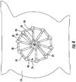
FIG. 1 is a side view in perspective of a radial compression device in accordance with the present invention, shown in an open orientation; -
FIG. 2 is a side view in perspective of a radial compression device in accordance with the present invention, shown in a closed orientation; -
FIG. 3 is a side view of the essential parts of the preferred embodiment of the present invention, showing the roughly isosceles-triangular-shaped die, the stationary plate, and rolling balls both between the die and between the die outer edges and the stationary plate, shown in an open orientation; -
FIG. 4 is a side view of the essential parts of the preferred embodiment of the present invention, showing the roughly isosceles-triangular-shaped die, the stationary plate, and rolling balls both between the die and between the die outer edges and the stationary plate, shown in a closed orientation; -
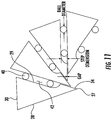
FIG. 5 is a perspective view of a complete die assembly of a preferred embodiment of the present invention showing the arms and rolling cam-follower bearings that move the die to create the open-to-closed motion; -
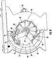
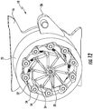
FIG. 6 is a side cutaway view in perspective of a radial compression device in accordance with the present invention, shown in a partly-open orientation, showing the die assemblies, the rolling balls, the stationary plates, and the rotating cam ring that actuates the die between the open and closed orientations; -
FIG. 7 illustrates an isosceles-triangular-shaped die, with a cutout to accommodate balls for guidance; -
FIG. 8 illustrates an isosceles-triangular-shaped die, without a cutout to accommodate balls for guidance; -
FIG. 9 is an enlarged side view of the working tips forming a cavity to illustrate the gap formed therebetween; -
FIG. 10 is a graphical representation of the relationship between die-to-die gap and cavity diameter for the present invention; -
FIG. 11 illustrates, the primary influencers of the die-to-die gap, namely, the die's step dimension and the ball diameter; and -
FIG. 12 is a side view of the radial compression device with the stationary plate removed illustrating return springs. - In this specifications the following non-SI units are used, which may be converted to the respective SI or metric unit according to the following conversion table:
Millimeters Centimeters Meters Kilometers Inches Feet Yards Miles mm cm m km in ft yd mi 1 0.1 0.001 0.000001 0.03937 0.003281 0.001094 6.21e-07 10 1 0.01 0.00001 0.393701 0.032808 0.010936 0.000006 1000 100 1 0.001 39.37008 3.28084 1.093613 0.000621 1000000 100000 1000 1 39370.08 3280.84 1093.613 0.621371 25.4 2.54 0.0254 0.000025 1 0.083333 0.027778 0.000016 304.8 30.48 0.3048 0.000305 12 1 0.333333 0.000189 914.4 91.44 0.9144 0.000914 36 3 1 0.000568 1609344 160934.4 1609.344 1.609344 63360 5280 1760 1 - Turning now to the drawings in which like reference characters indicate corresponding elements throughout the several views, attention is first directed to
FIGS. 1 ,2 and6 , which illustrate aradial compression device 10 in accordance with the present invention.Device 10 includes a constrainingstructure 12, which in this preferred embodiment includes a pair of spaced apartstationary plates plate surfaces 20, is a general polygonal shape, with each bearingsurface 20 forming a side of the polygonal shape. Cut-outs Plates plates structure 12, as long a cut-out defined by bearing surfaces is present. -
Device 10 further includes a plurality ofdie 24 carried within cut-outs stationary plates plate 14 to cut-out 19 ofplate 16. Plurality ofdie 24 are arranged in a generally circular pattern about a central axis, constrained by constrainingstructure 12 and movable between an open position and a closed position. A driving mechanism is coupled to at least one of the plurality ofdie 24 to drive all of the die in unison between the open position and the closed position. In the preferred embodment, the driving mechanism includes arotating cam element 25 reciprocally rotatably carried betweenstationary plates arm 26 driven by an actuating force. The actuating force can be provided by substantially any means, including electric motor, mechanical, manual and the like.Die 24 are moved within cut-outs cam element 25 between the open position (FIG. 1 ) and the closed position (FIG. 2 ) which can have an accurately round cavity at diameters as small as 0.3 mm. - Still referring to
FIGS. 1 ,2 and6 , each die 24 is an isosceles-triangle or wedge shape, with avertex 27 defined by convergingsides 28 and 29 (FIG. 8 ).Vertex 27 preferably has an angle of approximately 36 degrees in the preferred embodiment. Each die 24 also includes abase side 30opposite vertex 27. The number of bearing surfaces 20 of cut-outs die 24 used. In the preferred embodiment, the polygonal shape of cut-outs die 24. It will be understood that more or less die 24 can be used, with the polygonal shape corresponding to the number selected. It should be noted that the number of die may be varied over the practical range of 3 to 15 depending on the requirements and desires of the manufacturer. It should also be noted that the decagon described here would, in the general case, be a regular polygon with a number of sides equal to the die count, and that the vertex angle of the isosceles-triangular-shaped die would in general be equal to 360 degrees divided by the number of die. - Plurality of
die 24 are arranged in a generally circular pattern about a central axis withsides 28 ofdie 24 in parallel juxtaposition withsides 29 ofadjacent die 24. This arrangement ofdie 24 is constrained within cut-outs base side 30 of each die of the plurality ofdie 24 is positioned adjacent one of the bearing surfaces 20 forming the sides of the polygonal cut-outs outs die 24, are chosen so that there is just enough space to pack die 24 within cut-outs stationary plates die 24 bear on and are guided by bearingsurfaces 20 andsides 28 ofdie 24 bear on and are guided bysides 29 ofadjacent die 24. One portion ofside 29 of each die 24, nearvertex 27, forms a workingsurface 34 that contacts a product, and cooperates with the other die' workingsurface 34 to define a central cylindrically-shaped product-receivingcavity 35 generally at the central axis of the circular pattern of arranged die 24. - As illustrated in
FIGS. 3 and4 , the above-described arrangement ofstationary plates die 24. Each die 24 is free to move only in linear motion relative to the stationary plates, and only along a direction parallel to bearingsurfaces 20 as indicated by arrowed line A, and only in unison with each other. Furthermore, this arrangement constrains each die 24 to move only in linear motion with respect to each of the twoadjacent die 24, namely a sliding motion betweensides 28 andsides 29 of adjacent die. Further still, this constrained and coordinated die motion results in a changing diameter of the central cylindrically-shaped product-receivingcavity 35 between the open position and the closed position. The motion is so completely constrained that, if bearing surfaces 20 were free of friction, a force applied to any one ofdie 24 would cause the whole group of die to move in unison to open or closecentral cavity 35. - The above-described arrangement of
die 24 also results in a constant die-to-die gap that does not vary depending on the diameter ofcentral cavity 35, as illustrated inFIGS. 9 and 10 . The dimension of the die-to-die gap may be designed to be any size, depending on the requirements of the application, but for many applications it should be as small as possible while preventing direct rubbing contact of workingtips 34, in accordance with the achievable manufacturing tolerances of the parts. In some applications, direct rubbing contact of the adjacent workingtips 34 may be allowable or desirable. - Contact between die 24 can be made by direct sliding contact of planar surfaces, with or without lubricating grease or oil or can be made to slide easier on one another and bearing
surfaces 20 by application of low friction materials, or by use of bearing elements such as rolling cylinders (also known commonly as "needle rollers") or by the use ofballs 40 as in the preferred embodiment illustrated.Bearing balls 40 are used for die-to-die bearing and guidance.Balls 40 are positioned betweenadjacent sides base 30 and bearing surfaces 20.Die 24 and rolling bearingballs 40 are preferably made from hard material such as hardened tool steel or hardened martensitic stainless steel or ceramic.Bearing balls 40 provide low friction, long service life with low wear, low maintenance, and very good guiding precision. In this embodiment, the precision of the die-to-die gaps is influenced only by a small number of parts comprising die 24 themselves and rolling bearingballs 40. - With reference to
FIGS. 7 and11 , die 24 can be modified to further reduce the gap created betweendie 24 by forming aninset step 42 alongside 29 of each die 24.Bearing balls 40 are carried between die 24 within inset steps 42, each of which act as a ball race. In this manner, friction betweendie 24 is reduced by bearingballs 40 while a very slight, if any, gap is created at workingtips 34. Only one aspect ofdie 24 is the primary factor influencing the gaps: the dimension ofinset step 42 between workingtip surface 34 and the ball-race surface, a feature that can easily be made to very high precision. For example, readily available metal cutting methods such as surface grinding or wire-cut EDM can make such cuts with accuracy plus or minus 0.0002 inches. Using those metal cutting methods, all of the relevant features ofdie 24 can be made without removing the part from the machine, thus avoiding dimension errors due to part fixturing on the cutting machine. Furthermore, bearingballs 40 of extremely high precision, for example, with diameter dimension 0.125 inch plus or minus 0.00005 inch, are commonly available and inexpensive. Because the die's step dimension and the ball diameter are the primary influence on the die-to-die gap dimension, the gap can be designed to be much smaller than that of prior-art mechanisms without danger of die-to-die rubbing that may cause excess friction and wear. - It should also be noted that the bearing and guidance that occurs between die 24 and
stationary plates adjacent die 24, may practically be achieved with a wide range of design elements, such as 1) direct sliding surface contact of the parts with or without lubricating grease or oil, or 2) by coating, laminating, or attaching various commonly-used friction-reducing or wear-enhancing materials, or 3) rolling cylinders (also known commonly as "needle rollers", or 4) cam-follower type ball bearing or plain bearings rolling on planer surfaces, or 5) rolling balls placed between the adjacent parts, as is shown in the embodiment inFIGS. 1-4 and6 . It should also be noted that the shape of the die, although shown to be isosceles triangular in this easy-to-illustrate embodiment, could in general take a wide variety of shapes, provided that the directions of linear motion allowed by the three bearing and guiding mechanisms engaging each die form an isosceles triangle. - Although
central cavity 35 ofdevice 10 can be opened or closed by a wide variety of actuating methods that apply a force to one ormore die 24, one preferred embodiment usesrotating cam element 25 to simultaneously actuate all die 24. Simultaneous actuation of all die 24 imposes lower forces on the bearing and guiding apparatus compared to actuation of just one or a few ofdie 24, though this is possible. Referring toFIGS. 5 and6 , a rotatingcam element 25 is rotatably coupled to and betweenstationary plates cam 25 includes acam surface 50 for each die 24. Referring specifically toFIG. 5 , each die includes a pair ofarms 52 terminating inrollers 54 also referred to as cam follower bearings.Arms 52 extend perpendicularly frombase 30 and are intermediatestationary plates housing 12. Cam surfaces 50 engage rollers or cam-follower bearings 54 of each die 24.Cam element 25 can be rotated to move die 24 between the open and the closed positions and continuously increase or decrease the diameter ofcentral cavity 35. In this embodiment, anactuating arm 26 is attached torotating cam element 25 such that a downward force onarm 26 from an actuator such as an air cylinder, handle, or electric motor closescentral cavity 35.Arm 26 can be operated continuously to increase or decrease the diameter of the central cavity. In one example of use, withcentral cavity 35 at maximum, any device to be radially compressed, such as a stent, balloon, catheter, etc, is inserted intocentral cavity 35.Arm 26 is then operated to continuously reduce the diameter ofcentral cavity 35 until the product is suitably compressed. - Turning to
FIG. 12 , die 24 are moved to a closed position bycam element 25, against a bias generated by return springs 60 carried betweenadjacent arms 52. Upon release ofroller 54 from cam surfaces 50, springs 60 bias die 24 to the open position. - Thus, a new and novel radial compression mechanism has been disclosed. The new and novel radial compression mechanism is constructed to operate with a constant gap between adjacent die and to move the die in unison between a maximum diameter central cavity and a minimum diameter central cavity with a continuous radial movement, and to be manufacturable with very small and precise gaps between adjacent die. Therefore, the large and variable gaps of some prior art devices, and the relatively imprecise gaps of other prior art devices have been overcome.
- Having fully described the invention in such clear and concise terms as to enable those skilled in the art to understand and practice the same, the invention claimed is:
Claims (9)
- A radial compression mechanism (10) comprising:a constraining structure (12) including a cut-out formed therethrough, the cut-out (18, 19) defined by a plurality of bearing surfaces (20);a plurality of die (24) carried by the constraining structure and arranged in a circular pattern about a central axis;each die of the plurality of die having a working surface (34), the working surfaces of the plurality of die cooperating to form a central product-receiving cylindrically-shaped cavity (35) that is movable between an open position and a closed position as the plurality of die move in unison; anda driving mechanism coupled to at least one of the plurality of die to drive all of the die in unison between the open position and the closed position,characterised in that:the constraining structure is stationary; andeach die of the plurality of die has a wedge shape with a base side (30) positioned in parallel juxtaposition to a corresponding bearing surface of the plurality of bearing surfaces, each die being constrained to move reciprocally and linearly along the corresponding bearing surface.
- A radial compression mechanism (10) as claimed in claim 1, wherein each of the plurality of die (24) have a sliding surface (28) opposite the working surface (34), the sliding surface of each die of the plurality of die being positioned in substantially parallel juxtaposition to the working surface of an adjacent die, a constant width gap being defined between the sliding surface of each die of the plurality of die and the working surface of each adjacent die of the plurality of die.
- A radial compression mechanism (10) as claimed in claim 1, wherein the driving mechanism includes a cam element (25) movable relative the constraining structure (12), the cam element has at least one cam surface (50) engaging at least one of the plurality of die (24), wherein movement of the cam element simultaneously drives all of the die in unison between the open position and the closed position.
- A radial compression mechanism (10) as claimed in claim 1, wherein the driving mechanism includes a cam element (25) movable relative the constraining structure, the cam element includes a plurality of cam surfaces (50), each cam surface corresponding to and engaging one die of the plurality of die (24), wherein movement of the cam element simultaneously drives all of the die in unison between the open position and the closed position.
- A radial compression mechanism (10) as claimed in claim 1, wherein the engagement between adjacent die of the plurality of die (24) and between each die and the corresponding bearing surface (20) is one of a direct sliding surface contact therebetween, coating, laminating, or attaching various friction-reducing or wear-enhancing materials therebetween, and positioning bearing elements therebetween.
- A radial compression mechanism (10) as claimed in claim 1, wherein the cut-out (18, 19) is a polygonal shapes and wherein each bearing surface (20) forms a side of the polygonal shape.
- A radial compression mechanism (10) as claimed in claim 1, wherein the plurality of die (24) includes between 3 and 15 die (24).
- A radial compression mechanism (10) as claimed in claim 1, wherein the central product-receiving cylindrically-shaped cavity (35) is as small as 0.3 mm in the closed position.
- A radial compression mechanism (10) as claimed in claim 1, wherein the constraining structure comprises:a first stationary plate (14) including a first cut-out (18) formed therethrough, the first cut-out defined by a plurality of bearing surfaces (20); anda second stationary plate (16) including a second cut-out (19) formed therethrough, the second cut-out defined by a plurality of bearing surfaces (20).
Applications Claiming Priority (3)
| Application Number | Priority Date | Filing Date | Title |
|---|---|---|---|
| US201562235075P | 2015-09-30 | 2015-09-30 | |
| US15/276,539 US9821363B2 (en) | 2015-09-30 | 2016-09-26 | Radial compression device with constrained dies |
| PCT/US2016/054360 WO2017059024A1 (en) | 2015-09-30 | 2016-09-29 | Radial compression device with constrained die |
Publications (3)
| Publication Number | Publication Date |
|---|---|
| EP3294232A1 EP3294232A1 (en) | 2018-03-21 |
| EP3294232A4 EP3294232A4 (en) | 2019-03-06 |
| EP3294232B1 true EP3294232B1 (en) | 2020-10-21 |
Family
ID=58406162
Family Applications (1)
| Application Number | Title | Priority Date | Filing Date |
|---|---|---|---|
| EP16852567.3A Active EP3294232B1 (en) | 2015-09-30 | 2016-09-29 | Radial compression device with constrained die |
Country Status (5)
| Country | Link |
|---|---|
| US (1) | US9821363B2 (en) |
| EP (1) | EP3294232B1 (en) |
| JP (1) | JP6703552B2 (en) |
| CN (1) | CN107949350B (en) |
| WO (1) | WO2017059024A1 (en) |
Families Citing this family (8)
| Publication number | Priority date | Publication date | Assignee | Title |
|---|---|---|---|---|
| WO2019199758A1 (en) * | 2018-04-09 | 2019-10-17 | Hubbell Incorporated | Decagon compression die |
| JP7326451B2 (en) | 2019-01-24 | 2023-08-15 | ブロックワイズ エンジニアリング エルエルシー | radial compression machine |
| US11229941B1 (en) * | 2019-04-22 | 2022-01-25 | Blockwise Engineering Llc | Radial compression mechanism |
| CN111468547B (en) * | 2020-05-30 | 2021-08-06 | 东台磊达钢帘线有限公司 | Wire drawing die |
| JP2023551330A (en) * | 2020-11-30 | 2023-12-07 | アークティック・バイオマテリアルズ・オサケユフティオ | Method and apparatus for producing fiber reinforced articles |
| JP2022155878A (en) * | 2021-03-31 | 2022-10-14 | テルモ株式会社 | shaping device |
| JP7485303B2 (en) * | 2021-03-31 | 2024-05-16 | テルモ株式会社 | Shaping device and shaping method |
| CN113334268B (en) * | 2021-05-10 | 2023-03-31 | 哈尔滨玻璃钢研究院有限公司 | Hinge soft-fit positioning tool and using method thereof |
Family Cites Families (15)
| Publication number | Priority date | Publication date | Assignee | Title |
|---|---|---|---|---|
| US1480077A (en) * | 1920-02-13 | 1924-01-08 | Edward E Johnson | Die-forging machine |
| US4041766A (en) * | 1976-06-03 | 1977-08-16 | Gte Sylvania Incorporated | Swaging device for use within a die apparatus |
| US4454657A (en) * | 1980-07-25 | 1984-06-19 | Japan Aviation Electronics Industry Limited | Aperture setting device |
| US4454857A (en) * | 1982-09-28 | 1984-06-19 | Miller Allen W | Peep sight for a bow |
| US5715723A (en) * | 1996-08-14 | 1998-02-10 | Owens; Carl H. | Hose crimping apparatus |
| US6925847B2 (en) * | 2002-08-31 | 2005-08-09 | Thomas Motsenbocker | Hand held stent crimping apparatus and method |
| EP1768630B1 (en) * | 2004-06-16 | 2015-01-07 | Machine Solutions, Inc. | Stent crimping device |
| WO2007010339A2 (en) * | 2005-07-19 | 2007-01-25 | Pi.Effe.Ci. S.R.L. | Tool for the connection of tubes by means of connection sleeves |
| US7530253B2 (en) * | 2005-09-09 | 2009-05-12 | Edwards Lifesciences Corporation | Prosthetic valve crimping device |
| US7963142B2 (en) * | 2006-08-22 | 2011-06-21 | Ed Goff | Radial compression mechanism with optimum die-to-die gap |
| US8245559B1 (en) * | 2007-04-11 | 2012-08-21 | Warriner Jeremiah J | Radial compression mechanism with optimum die-to-die gap |
| US8220307B2 (en) * | 2007-08-21 | 2012-07-17 | Ed Goff | Radial compression mechanism with optimum die-to-die gap |
| TW201008714A (en) * | 2008-07-02 | 2010-03-01 | Rennsteig Werkzeuge Gmbh | Crimping tool |
| JP2014523294A (en) * | 2011-06-20 | 2014-09-11 | マシーン ソリューションズ インコーポレイテッド | Apparatus and method for loading a delivery tube with a stent |
| CA2862126C (en) * | 2011-12-31 | 2016-11-08 | The Gates Corporation | Crimper system |
-
2016
- 2016-09-26 US US15/276,539 patent/US9821363B2/en active Active
- 2016-09-29 JP JP2017560323A patent/JP6703552B2/en active Active
- 2016-09-29 CN CN201680031081.9A patent/CN107949350B/en active Active
- 2016-09-29 EP EP16852567.3A patent/EP3294232B1/en active Active
- 2016-09-29 WO PCT/US2016/054360 patent/WO2017059024A1/en active Application Filing
Non-Patent Citations (1)
| Title |
|---|
| None * |
Also Published As
| Publication number | Publication date |
|---|---|
| WO2017059024A8 (en) | 2018-09-20 |
| JP6703552B2 (en) | 2020-06-03 |
| CN107949350A (en) | 2018-04-20 |
| JP2018531629A (en) | 2018-11-01 |
| EP3294232A4 (en) | 2019-03-06 |
| WO2017059024A1 (en) | 2017-04-06 |
| EP3294232A1 (en) | 2018-03-21 |
| US9821363B2 (en) | 2017-11-21 |
| US20170087620A1 (en) | 2017-03-30 |
| CN107949350B (en) | 2020-09-15 |
Similar Documents
| Publication | Publication Date | Title |
|---|---|---|
| EP3294232B1 (en) | Radial compression device with constrained die | |
| US7963142B2 (en) | Radial compression mechanism with optimum die-to-die gap | |
| US7886661B1 (en) | Radial compression mechanism | |
| US8245559B1 (en) | Radial compression mechanism with optimum die-to-die gap | |
| US8220307B2 (en) | Radial compression mechanism with optimum die-to-die gap | |
| US8702414B1 (en) | Lip adjustment push system | |
| EP3914199B1 (en) | Radial compression machine | |
| JP6790391B2 (en) | Rolling bearing ellipse measuring device, ellipse measuring method, and rolling bearing manufacturing method | |
| KR20130026147A (en) | Jig for piston ring and laser surface texturing method using the same | |
| WO2016017119A1 (en) | Bearing bush for use in toggle | |
| US11229941B1 (en) | Radial compression mechanism | |
| TWI790298B (en) | Tire building apparatus and method for joining or cutting tire components | |
| KR101171845B1 (en) | Mobile apparatus for measuring circularity | |
| CN209102528U (en) | A kind of reinforcing steel bar bending tester | |
| JP2003097552A (en) | Friction applying device and linear motion guide | |
| US7886566B1 (en) | Swager die and actuator mechanism | |
| CN109153059B (en) | Method and apparatus for forming helical threads | |
| US4230009A (en) | Rotary tool positioner | |
| JP7285137B2 (en) | Mover and roller guide device | |
| JP2010012559A (en) | Snap ring contraction device | |
| US9459083B2 (en) | Positioning goniometry | |
| JP2021084130A (en) | Swaging device, swaging method and swaging workpiece | |
| JP6342365B2 (en) | Roll forming equipment | |
| JP6618791B2 (en) | Belt wrapper | |
| US20090046959A1 (en) | Movement Device |
Legal Events
| Date | Code | Title | Description |
|---|---|---|---|
| STAA | Information on the status of an ep patent application or granted ep patent |
Free format text: STATUS: THE INTERNATIONAL PUBLICATION HAS BEEN MADE |
|
| PUAI | Public reference made under article 153(3) epc to a published international application that has entered the european phase |
Free format text: ORIGINAL CODE: 0009012 |
|
| STAA | Information on the status of an ep patent application or granted ep patent |
Free format text: STATUS: REQUEST FOR EXAMINATION WAS MADE |
|
| 17P | Request for examination filed |
Effective date: 20171214 |
|
| AK | Designated contracting states |
Kind code of ref document: A1 Designated state(s): AL AT BE BG CH CY CZ DE DK EE ES FI FR GB GR HR HU IE IS IT LI LT LU LV MC MK MT NL NO PL PT RO RS SE SI SK SM TR |
|
| AX | Request for extension of the european patent |
Extension state: BA ME |
|
| RIN1 | Information on inventor provided before grant (corrected) |
Inventor name: WARRINER, JEREMIAH, J. Inventor name: GOFF, ED |
|
| RIN1 | Information on inventor provided before grant (corrected) |
Inventor name: WARRINER, JEREMIAH J. Inventor name: GOFF, ED |
|
| DAV | Request for validation of the european patent (deleted) | ||
| DAX | Request for extension of the european patent (deleted) | ||
| A4 | Supplementary search report drawn up and despatched |
Effective date: 20190131 |
|
| RIC1 | Information provided on ipc code assigned before grant |
Ipc: A61F 2/82 20130101ALI20190125BHEP Ipc: B21J 7/16 20060101ALI20190125BHEP Ipc: A61F 2/844 20130101AFI20190125BHEP Ipc: B25B 27/10 20060101ALI20190125BHEP Ipc: A61F 2/06 20130101ALI20190125BHEP Ipc: B21C 3/06 20060101ALI20190125BHEP Ipc: A61F 2/95 20130101ALI20190125BHEP Ipc: B30B 7/04 20060101ALI20190125BHEP Ipc: A61F 2/07 20130101ALI20190125BHEP Ipc: B21D 41/04 20060101ALI20190125BHEP |
|
| GRAP | Despatch of communication of intention to grant a patent |
Free format text: ORIGINAL CODE: EPIDOSNIGR1 |
|
| STAA | Information on the status of an ep patent application or granted ep patent |
Free format text: STATUS: GRANT OF PATENT IS INTENDED |
|
| INTG | Intention to grant announced |
Effective date: 20200430 |
|
| GRAS | Grant fee paid |
Free format text: ORIGINAL CODE: EPIDOSNIGR3 |
|
| GRAA | (expected) grant |
Free format text: ORIGINAL CODE: 0009210 |
|
| STAA | Information on the status of an ep patent application or granted ep patent |
Free format text: STATUS: THE PATENT HAS BEEN GRANTED |
|
| AK | Designated contracting states |
Kind code of ref document: B1 Designated state(s): AL AT BE BG CH CY CZ DE DK EE ES FI FR GB GR HR HU IE IS IT LI LT LU LV MC MK MT NL NO PL PT RO RS SE SI SK SM TR |
|
| REG | Reference to a national code |
Ref country code: GB Ref legal event code: FG4D |
|
| REG | Reference to a national code |
Ref country code: CH Ref legal event code: NV Representative=s name: ISLER AND PEDRAZZINI AG, CH Ref country code: CH Ref legal event code: EP |
|
| REG | Reference to a national code |
Ref country code: IE Ref legal event code: FG4D |
|
| REG | Reference to a national code |
Ref country code: DE Ref legal event code: R096 Ref document number: 602016046453 Country of ref document: DE |
|
| REG | Reference to a national code |
Ref country code: AT Ref legal event code: REF Ref document number: 1325066 Country of ref document: AT Kind code of ref document: T Effective date: 20201115 |
|
| REG | Reference to a national code |
Ref country code: NL Ref legal event code: FP |
|
| REG | Reference to a national code |
Ref country code: AT Ref legal event code: MK05 Ref document number: 1325066 Country of ref document: AT Kind code of ref document: T Effective date: 20201021 |
|
| PG25 | Lapsed in a contracting state [announced via postgrant information from national office to epo] |
Ref country code: FI Free format text: LAPSE BECAUSE OF FAILURE TO SUBMIT A TRANSLATION OF THE DESCRIPTION OR TO PAY THE FEE WITHIN THE PRESCRIBED TIME-LIMIT Effective date: 20201021 Ref country code: GR Free format text: LAPSE BECAUSE OF FAILURE TO SUBMIT A TRANSLATION OF THE DESCRIPTION OR TO PAY THE FEE WITHIN THE PRESCRIBED TIME-LIMIT Effective date: 20210122 Ref country code: NO Free format text: LAPSE BECAUSE OF FAILURE TO SUBMIT A TRANSLATION OF THE DESCRIPTION OR TO PAY THE FEE WITHIN THE PRESCRIBED TIME-LIMIT Effective date: 20210121 Ref country code: PT Free format text: LAPSE BECAUSE OF FAILURE TO SUBMIT A TRANSLATION OF THE DESCRIPTION OR TO PAY THE FEE WITHIN THE PRESCRIBED TIME-LIMIT Effective date: 20210222 Ref country code: RS Free format text: LAPSE BECAUSE OF FAILURE TO SUBMIT A TRANSLATION OF THE DESCRIPTION OR TO PAY THE FEE WITHIN THE PRESCRIBED TIME-LIMIT Effective date: 20201021 |
|
| REG | Reference to a national code |
Ref country code: LT Ref legal event code: MG4D |
|
| PG25 | Lapsed in a contracting state [announced via postgrant information from national office to epo] |
Ref country code: SE Free format text: LAPSE BECAUSE OF FAILURE TO SUBMIT A TRANSLATION OF THE DESCRIPTION OR TO PAY THE FEE WITHIN THE PRESCRIBED TIME-LIMIT Effective date: 20201021 Ref country code: IS Free format text: LAPSE BECAUSE OF FAILURE TO SUBMIT A TRANSLATION OF THE DESCRIPTION OR TO PAY THE FEE WITHIN THE PRESCRIBED TIME-LIMIT Effective date: 20210221 Ref country code: LV Free format text: LAPSE BECAUSE OF FAILURE TO SUBMIT A TRANSLATION OF THE DESCRIPTION OR TO PAY THE FEE WITHIN THE PRESCRIBED TIME-LIMIT Effective date: 20201021 Ref country code: PL Free format text: LAPSE BECAUSE OF FAILURE TO SUBMIT A TRANSLATION OF THE DESCRIPTION OR TO PAY THE FEE WITHIN THE PRESCRIBED TIME-LIMIT Effective date: 20201021 Ref country code: BG Free format text: LAPSE BECAUSE OF FAILURE TO SUBMIT A TRANSLATION OF THE DESCRIPTION OR TO PAY THE FEE WITHIN THE PRESCRIBED TIME-LIMIT Effective date: 20210121 Ref country code: AT Free format text: LAPSE BECAUSE OF FAILURE TO SUBMIT A TRANSLATION OF THE DESCRIPTION OR TO PAY THE FEE WITHIN THE PRESCRIBED TIME-LIMIT Effective date: 20201021 Ref country code: ES Free format text: LAPSE BECAUSE OF FAILURE TO SUBMIT A TRANSLATION OF THE DESCRIPTION OR TO PAY THE FEE WITHIN THE PRESCRIBED TIME-LIMIT Effective date: 20201021 |
|
| PG25 | Lapsed in a contracting state [announced via postgrant information from national office to epo] |
Ref country code: HR Free format text: LAPSE BECAUSE OF FAILURE TO SUBMIT A TRANSLATION OF THE DESCRIPTION OR TO PAY THE FEE WITHIN THE PRESCRIBED TIME-LIMIT Effective date: 20201021 |
|
| REG | Reference to a national code |
Ref country code: DE Ref legal event code: R097 Ref document number: 602016046453 Country of ref document: DE |
|
| PG25 | Lapsed in a contracting state [announced via postgrant information from national office to epo] |
Ref country code: SM Free format text: LAPSE BECAUSE OF FAILURE TO SUBMIT A TRANSLATION OF THE DESCRIPTION OR TO PAY THE FEE WITHIN THE PRESCRIBED TIME-LIMIT Effective date: 20201021 Ref country code: LT Free format text: LAPSE BECAUSE OF FAILURE TO SUBMIT A TRANSLATION OF THE DESCRIPTION OR TO PAY THE FEE WITHIN THE PRESCRIBED TIME-LIMIT Effective date: 20201021 Ref country code: CZ Free format text: LAPSE BECAUSE OF FAILURE TO SUBMIT A TRANSLATION OF THE DESCRIPTION OR TO PAY THE FEE WITHIN THE PRESCRIBED TIME-LIMIT Effective date: 20201021 Ref country code: EE Free format text: LAPSE BECAUSE OF FAILURE TO SUBMIT A TRANSLATION OF THE DESCRIPTION OR TO PAY THE FEE WITHIN THE PRESCRIBED TIME-LIMIT Effective date: 20201021 Ref country code: SK Free format text: LAPSE BECAUSE OF FAILURE TO SUBMIT A TRANSLATION OF THE DESCRIPTION OR TO PAY THE FEE WITHIN THE PRESCRIBED TIME-LIMIT Effective date: 20201021 Ref country code: RO Free format text: LAPSE BECAUSE OF FAILURE TO SUBMIT A TRANSLATION OF THE DESCRIPTION OR TO PAY THE FEE WITHIN THE PRESCRIBED TIME-LIMIT Effective date: 20201021 |
|
| PLBE | No opposition filed within time limit |
Free format text: ORIGINAL CODE: 0009261 |
|
| STAA | Information on the status of an ep patent application or granted ep patent |
Free format text: STATUS: NO OPPOSITION FILED WITHIN TIME LIMIT |
|
| PG25 | Lapsed in a contracting state [announced via postgrant information from national office to epo] |
Ref country code: DK Free format text: LAPSE BECAUSE OF FAILURE TO SUBMIT A TRANSLATION OF THE DESCRIPTION OR TO PAY THE FEE WITHIN THE PRESCRIBED TIME-LIMIT Effective date: 20201021 |
|
| 26N | No opposition filed |
Effective date: 20210722 |
|
| PG25 | Lapsed in a contracting state [announced via postgrant information from national office to epo] |
Ref country code: AL Free format text: LAPSE BECAUSE OF FAILURE TO SUBMIT A TRANSLATION OF THE DESCRIPTION OR TO PAY THE FEE WITHIN THE PRESCRIBED TIME-LIMIT Effective date: 20201021 Ref country code: IT Free format text: LAPSE BECAUSE OF FAILURE TO SUBMIT A TRANSLATION OF THE DESCRIPTION OR TO PAY THE FEE WITHIN THE PRESCRIBED TIME-LIMIT Effective date: 20201021 |
|
| PG25 | Lapsed in a contracting state [announced via postgrant information from national office to epo] |
Ref country code: SI Free format text: LAPSE BECAUSE OF FAILURE TO SUBMIT A TRANSLATION OF THE DESCRIPTION OR TO PAY THE FEE WITHIN THE PRESCRIBED TIME-LIMIT Effective date: 20201021 |
|
| REG | Reference to a national code |
Ref country code: BE Ref legal event code: MM Effective date: 20210930 |
|
| PG25 | Lapsed in a contracting state [announced via postgrant information from national office to epo] |
Ref country code: IS Free format text: LAPSE BECAUSE OF FAILURE TO SUBMIT A TRANSLATION OF THE DESCRIPTION OR TO PAY THE FEE WITHIN THE PRESCRIBED TIME-LIMIT Effective date: 20210221 Ref country code: MC Free format text: LAPSE BECAUSE OF FAILURE TO SUBMIT A TRANSLATION OF THE DESCRIPTION OR TO PAY THE FEE WITHIN THE PRESCRIBED TIME-LIMIT Effective date: 20201021 |
|
| PG25 | Lapsed in a contracting state [announced via postgrant information from national office to epo] |
Ref country code: LU Free format text: LAPSE BECAUSE OF NON-PAYMENT OF DUE FEES Effective date: 20210929 Ref country code: BE Free format text: LAPSE BECAUSE OF NON-PAYMENT OF DUE FEES Effective date: 20210930 |
|
| PG25 | Lapsed in a contracting state [announced via postgrant information from national office to epo] |
Ref country code: HU Free format text: LAPSE BECAUSE OF FAILURE TO SUBMIT A TRANSLATION OF THE DESCRIPTION OR TO PAY THE FEE WITHIN THE PRESCRIBED TIME-LIMIT; INVALID AB INITIO Effective date: 20160929 |
|
| PG25 | Lapsed in a contracting state [announced via postgrant information from national office to epo] |
Ref country code: CY Free format text: LAPSE BECAUSE OF FAILURE TO SUBMIT A TRANSLATION OF THE DESCRIPTION OR TO PAY THE FEE WITHIN THE PRESCRIBED TIME-LIMIT Effective date: 20201021 |
|
| PGFP | Annual fee paid to national office [announced via postgrant information from national office to epo] |
Ref country code: NL Payment date: 20230816 Year of fee payment: 8 |
|
| PGFP | Annual fee paid to national office [announced via postgrant information from national office to epo] |
Ref country code: IE Payment date: 20230809 Year of fee payment: 8 Ref country code: GB Payment date: 20230810 Year of fee payment: 8 |
|
| PGFP | Annual fee paid to national office [announced via postgrant information from national office to epo] |
Ref country code: FR Payment date: 20230808 Year of fee payment: 8 Ref country code: DE Payment date: 20230802 Year of fee payment: 8 |
|
| PGFP | Annual fee paid to national office [announced via postgrant information from national office to epo] |
Ref country code: CH Payment date: 20231001 Year of fee payment: 8 |
|
| PG25 | Lapsed in a contracting state [announced via postgrant information from national office to epo] |
Ref country code: MK Free format text: LAPSE BECAUSE OF FAILURE TO SUBMIT A TRANSLATION OF THE DESCRIPTION OR TO PAY THE FEE WITHIN THE PRESCRIBED TIME-LIMIT Effective date: 20201021 |