EP3294187B1 - Medical instrument holder - Google Patents
Medical instrument holder Download PDFInfo
- Publication number
- EP3294187B1 EP3294187B1 EP17758438.0A EP17758438A EP3294187B1 EP 3294187 B1 EP3294187 B1 EP 3294187B1 EP 17758438 A EP17758438 A EP 17758438A EP 3294187 B1 EP3294187 B1 EP 3294187B1
- Authority
- EP
- European Patent Office
- Prior art keywords
- holder
- axis
- along
- external object
- displacement
- Prior art date
- Legal status (The legal status is an assumption and is not a legal conclusion. Google has not performed a legal analysis and makes no representation as to the accuracy of the status listed.)
- Active
Links
- 238000006073 displacement reaction Methods 0.000 claims description 49
- 230000008878 coupling Effects 0.000 claims description 41
- 238000010168 coupling process Methods 0.000 claims description 41
- 238000005859 coupling reaction Methods 0.000 claims description 41
- 238000001356 surgical procedure Methods 0.000 description 15
- 238000002357 laparoscopic surgery Methods 0.000 description 9
- 210000001015 abdomen Anatomy 0.000 description 7
- 241001631457 Cannula Species 0.000 description 5
- 230000007246 mechanism Effects 0.000 description 5
- 238000012978 minimally invasive surgical procedure Methods 0.000 description 4
- 238000013459 approach Methods 0.000 description 2
- 210000000056 organ Anatomy 0.000 description 2
- 241000557626 Corvus corax Species 0.000 description 1
- 238000012084 abdominal surgery Methods 0.000 description 1
- 210000003815 abdominal wall Anatomy 0.000 description 1
- 210000000038 chest Anatomy 0.000 description 1
- 238000002674 endoscopic surgery Methods 0.000 description 1
- 238000012977 invasive surgical procedure Methods 0.000 description 1
- 238000002324 minimally invasive surgery Methods 0.000 description 1
- 210000003205 muscle Anatomy 0.000 description 1
- 238000004659 sterilization and disinfection Methods 0.000 description 1
- 239000013501 sustainable material Substances 0.000 description 1
- 230000001360 synchronised effect Effects 0.000 description 1
Images


Classifications
-
- A—HUMAN NECESSITIES
- A61—MEDICAL OR VETERINARY SCIENCE; HYGIENE
- A61B—DIAGNOSIS; SURGERY; IDENTIFICATION
- A61B90/00—Instruments, implements or accessories specially adapted for surgery or diagnosis and not covered by any of the groups A61B1/00 - A61B50/00, e.g. for luxation treatment or for protecting wound edges
- A61B90/50—Supports for surgical instruments, e.g. articulated arms
-
- A—HUMAN NECESSITIES
- A61—MEDICAL OR VETERINARY SCIENCE; HYGIENE
- A61B—DIAGNOSIS; SURGERY; IDENTIFICATION
- A61B90/00—Instruments, implements or accessories specially adapted for surgery or diagnosis and not covered by any of the groups A61B1/00 - A61B50/00, e.g. for luxation treatment or for protecting wound edges
- A61B90/10—Instruments, implements or accessories specially adapted for surgery or diagnosis and not covered by any of the groups A61B1/00 - A61B50/00, e.g. for luxation treatment or for protecting wound edges for stereotaxic surgery, e.g. frame-based stereotaxis
- A61B90/11—Instruments, implements or accessories specially adapted for surgery or diagnosis and not covered by any of the groups A61B1/00 - A61B50/00, e.g. for luxation treatment or for protecting wound edges for stereotaxic surgery, e.g. frame-based stereotaxis with guides for needles or instruments, e.g. arcuate slides or ball joints
-
- A—HUMAN NECESSITIES
- A61—MEDICAL OR VETERINARY SCIENCE; HYGIENE
- A61B—DIAGNOSIS; SURGERY; IDENTIFICATION
- A61B34/00—Computer-aided surgery; Manipulators or robots specially adapted for use in surgery
- A61B34/30—Surgical robots
-
- A—HUMAN NECESSITIES
- A61—MEDICAL OR VETERINARY SCIENCE; HYGIENE
- A61B—DIAGNOSIS; SURGERY; IDENTIFICATION
- A61B1/00—Instruments for performing medical examinations of the interior of cavities or tubes of the body by visual or photographical inspection, e.g. endoscopes; Illuminating arrangements therefor
- A61B1/00147—Holding or positioning arrangements
- A61B1/00149—Holding or positioning arrangements using articulated arms
-
- A—HUMAN NECESSITIES
- A61—MEDICAL OR VETERINARY SCIENCE; HYGIENE
- A61B—DIAGNOSIS; SURGERY; IDENTIFICATION
- A61B1/00—Instruments for performing medical examinations of the interior of cavities or tubes of the body by visual or photographical inspection, e.g. endoscopes; Illuminating arrangements therefor
- A61B1/313—Instruments for performing medical examinations of the interior of cavities or tubes of the body by visual or photographical inspection, e.g. endoscopes; Illuminating arrangements therefor for introducing through surgical openings, e.g. laparoscopes
- A61B1/3132—Instruments for performing medical examinations of the interior of cavities or tubes of the body by visual or photographical inspection, e.g. endoscopes; Illuminating arrangements therefor for introducing through surgical openings, e.g. laparoscopes for laparoscopy
-
- A—HUMAN NECESSITIES
- A61—MEDICAL OR VETERINARY SCIENCE; HYGIENE
- A61B—DIAGNOSIS; SURGERY; IDENTIFICATION
- A61B17/00—Surgical instruments, devices or methods, e.g. tourniquets
- A61B17/00234—Surgical instruments, devices or methods, e.g. tourniquets for minimally invasive surgery
-
- A—HUMAN NECESSITIES
- A61—MEDICAL OR VETERINARY SCIENCE; HYGIENE
- A61B—DIAGNOSIS; SURGERY; IDENTIFICATION
- A61B17/00—Surgical instruments, devices or methods, e.g. tourniquets
- A61B17/34—Trocars; Puncturing needles
- A61B17/3417—Details of tips or shafts, e.g. grooves, expandable, bendable; Multiple coaxial sliding cannulas, e.g. for dilating
- A61B17/3421—Cannulas
- A61B17/3423—Access ports, e.g. toroid shape introducers for instruments or hands
-
- A—HUMAN NECESSITIES
- A61—MEDICAL OR VETERINARY SCIENCE; HYGIENE
- A61B—DIAGNOSIS; SURGERY; IDENTIFICATION
- A61B17/00—Surgical instruments, devices or methods, e.g. tourniquets
- A61B2017/00477—Coupling
-
- A—HUMAN NECESSITIES
- A61—MEDICAL OR VETERINARY SCIENCE; HYGIENE
- A61B—DIAGNOSIS; SURGERY; IDENTIFICATION
- A61B17/00—Surgical instruments, devices or methods, e.g. tourniquets
- A61B17/34—Trocars; Puncturing needles
- A61B17/3403—Needle locating or guiding means
- A61B2017/3405—Needle locating or guiding means using mechanical guide means
-
- A—HUMAN NECESSITIES
- A61—MEDICAL OR VETERINARY SCIENCE; HYGIENE
- A61B—DIAGNOSIS; SURGERY; IDENTIFICATION
- A61B34/00—Computer-aided surgery; Manipulators or robots specially adapted for use in surgery
- A61B34/30—Surgical robots
- A61B2034/301—Surgical robots for introducing or steering flexible instruments inserted into the body, e.g. catheters or endoscopes
-
- A—HUMAN NECESSITIES
- A61—MEDICAL OR VETERINARY SCIENCE; HYGIENE
- A61B—DIAGNOSIS; SURGERY; IDENTIFICATION
- A61B34/00—Computer-aided surgery; Manipulators or robots specially adapted for use in surgery
- A61B34/30—Surgical robots
- A61B2034/305—Details of wrist mechanisms at distal ends of robotic arms
Definitions
- the present invention is directed to a holder which has to be combined with an external object whereby the external object moves around a remote centre of motion.
- the external object preferably is a medical instrument such as a cannula or trocar whereby the remote centre of motion is the incision in the patient's abdomen.
- the holder can be used to support another object, in a particular embodiment a camera, convenient for performing endoscopic surgery, including in video-assisted thoracoscopic surgery, laparoscopic surgery and arthroscopic surgery; and is equipped with means for generating motion, both in a longitudinal and rotational manner following XYZ coordinates.
- the holder of the present invention is particularly useful for working in small areas as it occupies only a small bedside space, without sacrificing on the functional work area of the instrument mounted in the holder.
- the laparoscopic surgical instruments generally include a laparoscope for viewing the surgical field, and working tools such as clamps, graspers, scissors, staplers, and needle holders.
- the working tools are similar to those used in conventional (open) surgery, except that the working tools are often thin and long with at one end tools working in the surgical field and at the other end handles manipulated by a surgeon.
- the surgeon passes instruments through the cannulas and manipulates them inside the abdomen by sliding them in and out through the cannulas, rotating them in the cannulas, and "levering" (pivoting) them around the centres of rotation approximately defined by the incisions in the muscles of the abdominal wall.
- This point is generally referred to as the Remote Centre of Motion (RCM).
- RCM Remote Centre of Motion
- the surgeon may need to manually constrain it to pivot around the RCM coincident with the incision.
- Manual support of the pivot point is particularly of importance when the surgeon employs laparoscopes or other heavy instruments.
- Mechanical clamping devices are used to support the instruments in fixed orientations, but these devices do not provide a remote centre of rotation for positioning the instruments around the RCM.
- RCM positioners have been developed relying on varying approaches to provide a remote centre of rotation and assist surgeons in minimal invasive surgery.
- the present approaches in guiding the instruments around the RCM can be categorized according to the kinematic mechanism used.
- One of the best-known mechanisms is the one employed in the RCM arm of the daVinci® surgical system ( US 7,108,688 ) and relies on a double-parallelogram to constrain a surgical instrument to move around a fixed centre of rotation.
- the major disadvantage of this double-parallelogram mechanism is that it requires a large amount of working space above the patient.
- the present invention differs that the first member is not only configured to allow a longitudinal displacement of its connection with the second member but is equally configured to allow rotation of the first member around its longitudinal axis.
- a further shoulder member is required instead. This not only has an impact on the space occupied by the instrument holder, but also means that more complex couplings are required between said shoulder member and the further elbow member present in US2013/331644 . No such further intermediate shoulder member is required in the instrument holder of the present invention, significantly reducing the space occupied and by relying on a first member configured to allow both a longitudinal and rotary motion of its connection with the second member along its longitudinal axis, the further design is greatly simplified without loss of functionality.
- US 6,406,472 discloses a medical instrument holder which has to be combined with an external object that moves around a remote centre of motion, having a first member oriented in line with an axis with its origin at the remote centre of motion of said object, having a second member which is connected by means of a pivotable connector to the first member at one end and wherein the first member is configured to allow a circumferential displacement of the pivotable connector along said axis of the first member.
- the goal of the present invention is to provide medical instrument holder for an object, in a particular embodiment a camera, during laparoscopic surgery or other high precision surgeries, i.e. minimal invasive surgical procedures such as video-assisted thoracoscopic surgery, and arthroscopic surgery, that has to be combined with another object, in a particular embodiment a cannula or trocar that moves around a remote centre of motion (the incision in the patient, for example the incision in the patient's abdomen in case of laparoscopic surgery).
- the external object is held at an isocenter (its remote centre of motion) and connected to the holder wherein the holder is configured to follow the motion of the external object around the isocenter (around the remote centre of motion).
- the RCM may be a fixed or non-fixed RCM.
- the present invention provides a medical instrument holder, said holder having a first member oriented in line with an axis, for example the X-axis of the XYZ coordinate, with its origin at the remote centre of motion.
- the holder further comprises a second member, which is connected at one end on a pivotable manner (pivotable connector) to the first member and having coupling means at the other end for connecting a certain object (the external object) that is able to move around a remote centre of motion, preferably a medical instrument such as a cannula or trocar;
- Said coupling means may be flexible, wherein said coupling means permit rotation in at least two planes and wherein said coupling means are displaced laterally relative to said X-axis by means of said second member.
- the first member of the holder is configured to allow a longitudinal displacement of the pivotable connector along said axis.
- the holder comprises; - a first member oriented in line with an axis, for example the X-axis of the XYZ coordinate, with its origin at the remote centre of motion; - a second member, which is connected at one end on a pivotable manner (pivotable connector) to the first member and having a flexible coupling at the other end for connecting a certain object (the external object) that is able to move around a remote centre of motion; characterized in that the first member is configured to allow a longitudinal displacement of the pivotable connector along said axis; and to allow said pivotable connector to rotate about said axis.
- the longitudinal displacement and the circumferential displacement of the pivotable connector along the longitudinal axis of the first member is realized by a fixed position of the pivotable connector at the first member and configuration elements allowing a longitudinal displacement of the first member along its longitudinal axis and allowing rotation of the first member along its longitudinal axis.
- the longitudinal displacement and the circumferential displacement of the pivotable connector along the longitudinal axis of the first member is realized by a slidable position of the pivotable connector at the first member and configuration elements in the first member including guides for the pivotable connector along its longitudinal axis and configuration elements allowing rotation of the first member along its longitudinal axis.
- the flexible coupling is exchangeable.
- the second member comprises an adaptor, enabling said flexible coupling to be placed at the free end of the second member.
- the holder comprises means to lock the moving members of the holder in-between the manipulation of the external object around its remote centre of motion.
- the moving members including the configuration elements of the first member to allow a longitudinal displacement of the pivotable connector along said X-axis and to allow said pivotable connector to rotate about said X-axis, wherein the configuration elements may allow a linear (3) and/or a concave-curved (4) displacement of the pivotable connection (2) along the longitudinal axis of the first member (100).
- the moving members further including the pivotable connection between the first and second member and eventually the flexible coupling between the second member and the external object.
- the holder comprises means to lock one or more of the moving members of the holder, said moving members being selected from the configuration elements of the first member to allow a longitudinal displacement of the pivotable connector along said X-axis; the configuration elements of the first member to allow rotation of the pivotable connector about said X-axis; the pivotable connection between the first and second member; and the flexible coupling between the second member and the external object.
- the medical instrument holder comprises means to lock the configuration elements of the first member to allow a longitudinal displacement of the pivotable connector along said X-axis; the configuration elements of the first member to allow rotation of the pivotable connector about said X-axis; and optionally the pivotable connection between the first and second member.
- the holder comprises means to lock the configuration elements of the first member to allow a longitudinal displacement of the pivotable connector along said X-axis; the configuration elements of the first member to allow rotation of the pivotable connector about said X-axis; the pivotable connection between the first and second member; and optionally the flexible coupling between the second member and the external object.
- the holder can be used passively, wherein the movement of the holder passively follows the manipulation of the external object around its isocenter.
- the holder is used actively and controls the movement of the external object around its isocenter.
- the device comprises means for generating motion, both in a longitudinal and rotational manner following XYZ coordinates, thereby holding a given object, such as a camera.
- the present invention provides a holder for an (external) object (300), in a particular embodiment a cannula or trocar for minimally invasive surgical procedures, said holder having two members.
- Fig 1 is a schematic overview of an embodiment of the holder.
- the holder in itself does not need to have a remote centre of motion, hence when to be used during minimally invasive surgical procedures it has to be combined with another object (300), in a particular embodiment a cannula or trocar that moves around a remote centre of motion (the incision in the patient) (8).
- the instrument holder of the instant application can be used during a minimally invasive surgical procedure selected from video-assisted thoracoscopic surgery, laparoscopic surgery, and arthroscopic surgery; more in particular laparoscopic surgery.
- the remote centre of motion coincides with the incision in the patient's abdomen.
- various tools or instruments like cannulas and trocars having a remote centre of motion like the narrow entry points in laparoscopic surgery or other high precision surgery, can be supported by this invention.
- various tools, like a laparoscope (10) can be inserted into said cannula or trocar and accordingly held by the holder of the instant application.
- the holder of present invention comprises a first member (100) which may be contained within a fixed body (14), and a second member (200) pivotally connected to one another by means of a pivotable connector (2); the second member having a coupling (object coupling) (5) to connect the holder to an (external) object (300) having an isocenter (8), and the first member comprising moving members to allow the object coupling (5) to follow the motion of the external object around the isocenter.
- the first member (100) is oriented roughly in line with the X-axis (1) of the XYZ coordinate with its origin at the remote centre of motion (8) of the external object (300).
- the holder is typically mounted in a tripod or mounting fixture in the proximity of the isocenter of the external object.
- the second member (200) is connected at one end on a pivotable manner (pivotable connection) (2) to the first member (100) and has coupling means (5) at the other end for engaging an (external) object (300), a medical instrument like a cannula or trocar in particular.
- said coupling means may be flexible, thereby permitting rotation in at least two planes and a displacement laterally relative to said X-axis by means of said second member.
- the first member (100) of the holder is configured to allow a longitudinal displacement of the pivotable connector (2) along the longitudinal axis of the first member and to allow said pivotable connector to rotate about said axis.
- the longitudinal displacement and the circumferential displacement of the pivotable connector (2) along the longitudinal axis of the first member (100) is realized by a fixed position of the pivotable connector (2) at the first member (100) and configuration elements allowing a longitudinal displacement of the first member (100) along its longitudinal axis and allowing rotation of the first member (100) along its longitudinal axis.
- the longitudinal displacement and the circumferential displacement of the pivotable connector (2) along the longitudinal axis of the first member (100) is realized by a slidable position of the pivotable connector (2) at the first member (100) and configuration elements in the first member (100) including guides for the pivotable connector (2) along its longitudinal axis and configuration elements allowing rotation of the first member (100) along its longitudinal axis.
- these guides may allow longitudinal displacement in a linear (11), concave-curved (12) manner or combination thereof (infra).
- the holder is equipped with means to lock the moving members of the holder in-between the manipulation of the external object around its remote centre of motion (8), such as for example with friction couplings for the pivot point (2) between the first (100) and second (200) member, as well as for the configuration elements (e.g. guides) of the first member (100) allowing for the longitudinal and rotational displacement of the pivotable connector (2) along the X-axis (1).
- these friction couplings can be locked using a manipulator.
- the manipulator uses air pressure to lock the friction couplings.
- the former may comprise releasable engaging means to retain said further instrument within the external object in a desired position.
- these releasable engaging means of the external object could equally consist of a friction coupling and in a preferred embodiment is being controlled by the same manipulator as the one used to release and engage the friction couplings present on the holder.
- the manipulator has full control in positioning the further instrument around the centre of motion of the external object (300) coupled to the holder of the instant application.
- the flexible coupling (5) is exchangeable.
- the second member comprises an adaptor, enabling said flexible coupling to be placed at the free end of the second member.
- the pivotable connection (2) between the first (100) and second (200) member follows in its longitudinal displacement along the X-axis (1) a linear displacement, which is the result of a linear configuration element, namely a linear guide (11) in the first member (100) of the holder.
- the pivot point (2) connecting the second member to the first member does not merely follow a straight line along the X-axis of the XYZ coordinate with its origin at the remote centre of motion of said object (300), when being longitudinally displaced along said axis.
- the longitudinal displacement of said point includes a concave curved (4) displacement, wherein the turning point of the concave is oriented away from said X-axis.
- the second member (200) comprises besides the first linearly displaced pivotable connection (2), a further guide connector (13) that fits in a second configuration element (12) (a concave - curved guide (12)) in the first member, and follows mainly a curved (4) displacement along the longitudinal axis of the first member.
- This embodiment results in a more constrained movement of the holder compared to the embodiment having only a linear displacement and makes it easier for the manipulator to make a more spherical rotation (front-, back-, sidewards) of the object coupling (5) connecting the external object (300) to the second member (200) around the remote centre of motion (8) of the external object.
- the guide connector (13) and the pivotable connection (2) are the same.
- the holder is made of sustainable materials, which in a certain embodiment are heat stable and therefore suitable for heat sterilisation.
- the present invention provides medical instrument a holder, particularly useful as an instrument (camera) holder in minimally invasive surgical procedures and differs from the current RCM manipulators in that the holder in itself does not need to have an RCM.
- the RCM is present in the object carried by the holder instead (herein also referred to as the external object).
- this external object is a trocar for laparoscopic or video-assisted thoracoscopic surgery and inserted into the incision of the patient's abdomen or thorax. When inserted this trocar is spatially constraint at said incision point, making this point to behave as a remote centre of motion for the trocar. Coupling the object to the holder of the instant application does not further constrain the manipulation of the object.
- the holder accordingly provides a compact solution to keep a laparoscope or endoscope at a desired orientation, without making concessions on the operational area of manipulation.
- This large operational area of manipulation is for example apparent in figure 2 showing the access area of the external object (300), in said example of a trocar, to the organ (9) in the patient.
Description
- The present invention is directed to a holder which has to be combined with an external object whereby the external object moves around a remote centre of motion. The external object preferably is a medical instrument such as a cannula or trocar whereby the remote centre of motion is the incision in the patient's abdomen. The holder can be used to support another object, in a particular embodiment a camera, convenient for performing endoscopic surgery, including in video-assisted thoracoscopic surgery, laparoscopic surgery and arthroscopic surgery; and is equipped with means for generating motion, both in a longitudinal and rotational manner following XYZ coordinates. The holder of the present invention is particularly useful for working in small areas as it occupies only a small bedside space, without sacrificing on the functional work area of the instrument mounted in the holder.
- In standard laparoscopic abdominal surgery, incisions are made into the abdomen, followed by insufflation of the patient's abdomen with gas, and passing through cannulas via the small (approximately 1/2 inch) incisions to provide entry ports for laparoscopic surgical instruments. The laparoscopic surgical instruments generally include a laparoscope for viewing the surgical field, and working tools such as clamps, graspers, scissors, staplers, and needle holders. The working tools are similar to those used in conventional (open) surgery, except that the working tools are often thin and long with at one end tools working in the surgical field and at the other end handles manipulated by a surgeon. To perform surgical procedures, the surgeon passes instruments through the cannulas and manipulates them inside the abdomen by sliding them in and out through the cannulas, rotating them in the cannulas, and "levering" (pivoting) them around the centres of rotation approximately defined by the incisions in the muscles of the abdominal wall. This point is generally referred to as the Remote Centre of Motion (RCM). To maintain accurate positional control of an instrument during surgery, the surgeon may need to manually constrain it to pivot around the RCM coincident with the incision. Manual support of the pivot point is particularly of importance when the surgeon employs laparoscopes or other heavy instruments. Mechanical clamping devices are used to support the instruments in fixed orientations, but these devices do not provide a remote centre of rotation for positioning the instruments around the RCM.
- Consequently, different RCM positioners have been developed relying on varying approaches to provide a remote centre of rotation and assist surgeons in minimal invasive surgery. The present approaches in guiding the instruments around the RCM can be categorized according to the kinematic mechanism used. One of the best-known mechanisms is the one employed in the RCM arm of the daVinci® surgical system (
US 7,108,688 ) and relies on a double-parallelogram to constrain a surgical instrument to move around a fixed centre of rotation. The major disadvantage of this double-parallelogram mechanism is that it requires a large amount of working space above the patient. - Other systems employ circular tracking arcs (such as the EndoBot of Rensselaer Polytechnic institute), a fixed isocenter (such as the CLEM of Institut Albert Bonniot), a spherical linkage mechanisms (such as the RAVEN of Univ. of Washington), a highly complex gear train (such as the CoBRASurge of Univ. of Nebraska-Lincoln), a synchronous belt system (such as the MicroHand A of Tianjin University) or a set of parallel linkages pivotably connected to a gripper at fixed distances from the remote centre of motion (such as the VESALIUS system described in
US2012/0132018 ). Another robotic system, based on a planar remote center of motion device is described inUS2013/123798 , as described in the review article of Kuo & Dai, 2009 "Robotics for Minimally Invasive Surgery: A Historical Review from the Perspective of Kinematics", in "International Symposium on History of Machines and Mechanisms", Springer Netherlands, ISBN: 978-1-4020-9484-2; pages 343-351. - It has been an objective of the present invention to provide an instrument holder which does not necessarily needs to have a fixed remote centre of motion but has to be combined with an external object (e.g. cannula, trocar, ...) whereby the external object moves around a RCM (fixed or not), in particular during video-assisted thoracoscopic surgery, laparoscopic surgery, and arthroscopic surgery; more in particular laparoscopic surgery. In great contrast with
US2013/331644 , describing an intelligent autonomous camera control for robotics with medical, military and space applications, requiring multiple members with a multitude of coupling types between said members to enable full spatial positioning of the camera, the instrument holder of the present is much simpler in design with only two base members to allow the external object to move around a RCM. Compared to the system described inUS2013/331644 , the present invention differs that the first member is not only configured to allow a longitudinal displacement of its connection with the second member but is equally configured to allow rotation of the first member around its longitudinal axis. InUS2013/331644 , a further shoulder member is required instead. This not only has an impact on the space occupied by the instrument holder, but also means that more complex couplings are required between said shoulder member and the further elbow member present inUS2013/331644 . No such further intermediate shoulder member is required in the instrument holder of the present invention, significantly reducing the space occupied and by relying on a first member configured to allow both a longitudinal and rotary motion of its connection with the second member along its longitudinal axis, the further design is greatly simplified without loss of functionality. -
US 6,406,472 discloses a medical instrument holder which has to be combined with an external object that moves around a remote centre of motion, having a first member oriented in line with an axis with its origin at the remote centre of motion of said object, having a second member which is connected by means of a pivotable connector to the first member at one end and wherein the first member is configured to allow a circumferential displacement of the pivotable connector along said axis of the first member. - In general, the goal of the present invention is to provide medical instrument holder for an object, in a particular embodiment a camera, during laparoscopic surgery or other high precision surgeries, i.e. minimal invasive surgical procedures such as video-assisted thoracoscopic surgery, and arthroscopic surgery, that has to be combined with another object, in a particular embodiment a cannula or trocar that moves around a remote centre of motion (the incision in the patient, for example the incision in the patient's abdomen in case of laparoscopic surgery). Expressed differently, the external object is held at an isocenter (its remote centre of motion) and connected to the holder wherein the holder is configured to follow the motion of the external object around the isocenter (around the remote centre of motion). The RCM may be a fixed or non-fixed RCM.
- In a first aspect, the present invention provides a medical instrument holder, said holder having a first member oriented in line with an axis, for example the X-axis of the XYZ coordinate, with its origin at the remote centre of motion. The holder further comprises a second member, which is connected at one end on a pivotable manner (pivotable connector) to the first member and having coupling means at the other end for connecting a certain object (the external object) that is able to move around a remote centre of motion, preferably a medical instrument such as a cannula or trocar; Said coupling means may be flexible, wherein said coupling means permit rotation in at least two planes and wherein said coupling means are displaced laterally relative to said X-axis by means of said second member. Furthermore, the first member of the holder is configured to allow a longitudinal displacement of the pivotable connector along said axis. Expressed differently, the holder comprises; - a first member oriented in line with an axis, for example the X-axis of the XYZ coordinate, with its origin at the remote centre of motion; - a second member, which is connected at one end on a pivotable manner (pivotable connector) to the first member and having a flexible coupling at the other end for connecting a certain object (the external object) that is able to move around a remote centre of motion; characterized in that the first member is configured to allow a longitudinal displacement of the pivotable connector along said axis; and to allow said pivotable connector to rotate about said axis.
- Per reference to the exemplified embodiments hereinafter, in one embodiment the longitudinal displacement and the circumferential displacement of the pivotable connector along the longitudinal axis of the first member is realized by a fixed position of the pivotable connector at the first member and configuration elements allowing a longitudinal displacement of the first member along its longitudinal axis and allowing rotation of the first member along its longitudinal axis. In another embodiment the longitudinal displacement and the circumferential displacement of the pivotable connector along the longitudinal axis of the first member is realized by a slidable position of the pivotable connector at the first member and configuration elements in the first member including guides for the pivotable connector along its longitudinal axis and configuration elements allowing rotation of the first member along its longitudinal axis.
- In a particular embodiment the flexible coupling is exchangeable. In this embodiment the second member comprises an adaptor, enabling said flexible coupling to be placed at the free end of the second member.
- Where the aforementioned configuration allows the holder to follow the motion of the external object around its remote centre of motion, it is a further object of the present invention to use the holder in securing the external object in a desired position. Hence in a further embodiment the holder comprises means to lock the moving members of the holder in-between the manipulation of the external object around its remote centre of motion. The moving members including the configuration elements of the first member to allow a longitudinal displacement of the pivotable connector along said X-axis and to allow said pivotable connector to rotate about said X-axis, wherein the configuration elements may allow a linear (3) and/or a concave-curved (4) displacement of the pivotable connection (2) along the longitudinal axis of the first member (100). The moving members further including the pivotable connection between the first and second member and eventually the flexible coupling between the second member and the external object. In one embodiment the holder comprises means to lock one or more of the moving members of the holder, said moving members being selected from the configuration elements of the first member to allow a longitudinal displacement of the pivotable connector along said X-axis; the configuration elements of the first member to allow rotation of the pivotable connector about said X-axis; the pivotable connection between the first and second member; and the flexible coupling between the second member and the external object. In a particular embodiment the medical instrument holder comprises means to lock the configuration elements of the first member to allow a longitudinal displacement of the pivotable connector along said X-axis; the configuration elements of the first member to allow rotation of the pivotable connector about said X-axis; and optionally the pivotable connection between the first and second member. In another particular embodiment the holder comprises means to lock the configuration elements of the first member to allow a longitudinal displacement of the pivotable connector along said X-axis; the configuration elements of the first member to allow rotation of the pivotable connector about said X-axis; the pivotable connection between the first and second member; and optionally the flexible coupling between the second member and the external object.
- As will be apparent to the skilled artisan, the holder can be used passively, wherein the movement of the holder passively follows the manipulation of the external object around its isocenter. Alternatively, the holder is used actively and controls the movement of the external object around its isocenter. Accordingly, in a further example, not part of the invention, the device comprises means for generating motion, both in a longitudinal and rotational manner following XYZ coordinates, thereby holding a given object, such as a camera.
- With specific reference now to the figures, it is stressed that the particulars shown are by way of example and for purposes of illustrative discussion of the different embodiments of the present invention only. They are presented in the cause of providing what is believed to be the most useful and readily description of the principles and conceptual aspects of the invention. In this regard no attempt is made to show structural details of the invention in more detail than is necessary for a fundamental understanding of the invention. The description taken with the drawings making apparent to those skilled in the art how the several forms of the invention may be embodied in practice.
-
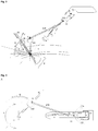
Fig. 1 : Schematic overview of an embodiment of an instrument holder according to the invention. Showing a first member (100) contained into a fixed body (14) with bearings, a second member (200) and the external object (300) (e.g. trocar, cannula, ...) coupled thereto and held spatially constrained at an isocenter (8). In this embodiment the flexible coupling means (5) and the external object (300) are fixed to each other. A laparascope (10) may be inserted into the external object (300).
In this embodiment, the first member (100) is able to rotate within the fixed body (14) around its longitudinal axis, i.e. an X-axis (1) as herein represented. Furthermore, the pivotable connection (2) between the first (100) and second (200) member follows via a configuration element (linear guide (11)) in the first member (100) a longitudinal displacement along the X-axis (1), allowing a linear (3) displacement along the longitudinal axis of the first member (100). Being spatially constrained at an isocenter (8) the external object should be able to follow a spherical space around said isocenter (8), thus requiring the capability of a rotational movement about a first (indicated by arrow (6)) and a second (indicated by arrow (7)) direction.
in the present embodiment of the instrument holder the rotational movement (6) is made possible by the movement caused by the pivotable connection (2) and the flexible coupling (5) together with the longitudinal displacement of the pivotable connection (2) in the linear guide (11), whereas rotational movement (7) is made possible because of the rotational movement of the first member (100) within the fixed body (14) along its longitudinal axis (1). Together these configuration elements enable movement of the flexible coupling according to rotational movement (6) and (7). -
Fig. 2 : Schematic overview of an embodiment of an instrument holder according to the invention. Showing a first member (100) contained into a fixed body (14) with bearings, a second member (200) and the external object (300) (e.g. trocar, cannula, ...) coupled thereto and held spatially constrained at an isocenter (8). In this embodiment the connection (in particular a releasable connection) (5) is a flexible connection (e.g. ball joint). In this embodiment the flexible coupling (5) and the external object (300) are NOT fixed to each other. A laparascope (10) may be inserted into the external object (300), wherein the access area of the external object (300) is the organ (9) of the patient.
In this embodiment, the first member (100) is able to rotate within the fixed body (14) around its longitudinal axis, e.g. an X-axis (1). Furthermore, the pivotable connection (2) between the first (100) and second (200) member follows via a first configuration element (linear guide (11)) in the first member (100) a longitudinal displacement along the X-axis (1), allowing a linear displacement (3) along the longitudinal axis of the first member (100). In addition, in this embodiment, the second member comprises a further guide connector (13) that fits in a second configuration element (12) (a concave -curved guide (12)) in the first member (100), and follows mainly a curved (4) displacement along the longitudinal axis of the first member (100).
Hence,in this embodiment rotational movement (6) is made possible by the movement caused by the pivotable connection (2), the guide connector (13) and the flexible coupling (5), whereas rotational movement (7) is made possible because of the rotational movement of the first member (100) within the fixed body (14) along its longitudinal axis (1), thereby allowing and together with the foregoing configuration elements, movement of the flexible coupling according to rotational movement (6) and (7). -
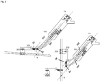
Fig. 3 : Schematic overview, showing three positions (A, B and C) for an instrument holder according to the invention and caused by the longitudinal displacement of second member (200) along the configuration elements (11, 12) in the first member (100) of the holder. A showing the fully retracted position. B showing an intermediate position. C showing a fully extended position. -
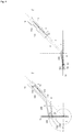
Fig. 4 : Schematic overview of an embodiment of an instrument holder according to the invention. Showing a first member (100) contained into a fixed body (14) with bearings, a second member (200) and the external object (300) (e.g. trocar, cannula, ...) coupled thereto and held spatially constrained at a fixed isocenter (8). In this embodiment, the second member (200) comprises two arms, an upper (X) and lower (Y) arm, each comprising a linear guide (11X), and (11Y) in the first member. The guide of the lower arm (11Y) even comprises a concave-curved guide (12) and a guide connector (13). Furthermore, each arm has its own coupling means (5X and 5Y), said coupling means being fixed together to the external object (300). A laparascope (10) may be inserted into the external object (300).
In this embodiment, the first member (100) is able to rotate within the fixed body (14) around its longitudinal axis, i.e. an axis (1) crossing the isocenter (8) as herein represented. Furthermore, the pivotable connection (2) between the first (100) and second (200) member follows via a configuration element (linear guide (11Y)) in the first member (100) a longitudinal displacement along the X-axis (1). Furthermore, the upper arm X having flexible means near the fixed body (14) enforces the angle of the movement. Being spatially constrained at an isocenter (8) the external object should be able to follow a spherical space (front-, back-, sidewards, ..) around said isocenter (8), thus requiring the capability of a rotational movement about a first (indicated by arrow (6X and 6Y)) direction. In the present embodiment of the instrument holder the rotational movement (6X and 6Y) is made possible by the movement caused by the pivotable connection (2) and the coupling means (5X and 5Y) together with the longitudinal displacement of the pivotable connection (2) in the linear guides (11X and 11Y), During this action, the lower arm will follow the rotational movement, whereas the upper arm enables the generation of a fixed isocenter (8). Evidently, speed of both arms contained within the first member varies during movement as it is function of both the rotational movement and the distance between the upper and lower arms. -
Fig. 5 : Schematic overview of an alternative embodiment of an instrument holder according to the invention. Showing a first member (100) contained into a fixed body (14) with bearings, a second member (200) and the external object (300) (e.g. trocar, cannula, ...) coupled thereto and held spatially constrained at an isocenter (8). In this embodiment the first member is configured to rotate along its longitudinal axis and comprises two arms (15X and 15Y) arranged at a distance, in parallel to each other and configured to allow a longitudinal displacement along the longitudinal axis of the first member at a fixed ratio with respect to the first member. Said first and second arm are pivotable coupled the second member at respective distances of the isocenter (2X and 2Y) at a ratio equal to the ratio of the translational displacement of the two arms vis-a-vis the first member, and characterized in that the external object is coupled to the second member by means of a flexible coupling (5). - The present invention provides a holder for an (external) object (300), in a particular embodiment a cannula or trocar for minimally invasive surgical procedures, said holder having two members.
Fig 1 is a schematic overview of an embodiment of the holder. In this embodiment the holder in itself does not need to have a remote centre of motion, hence when to be used during minimally invasive surgical procedures it has to be combined with another object (300), in a particular embodiment a cannula or trocar that moves around a remote centre of motion (the incision in the patient) (8). The instrument holder of the instant application can be used during a minimally invasive surgical procedure selected from video-assisted thoracoscopic surgery, laparoscopic surgery, and arthroscopic surgery; more in particular laparoscopic surgery. In said last embodiment the remote centre of motion coincides with the incision in the patient's abdomen. Not being limited to laparoscopic surgery, various tools or instruments like cannulas and trocars having a remote centre of motion, like the narrow entry points in laparoscopic surgery or other high precision surgery, can be supported by this invention. In said embodiment wherein the object is a cannula or trocar, various tools, like a laparoscope (10) can be inserted into said cannula or trocar and accordingly held by the holder of the instant application. - As already outlined herein before, the holder of present invention comprises a first member (100) which may be contained within a fixed body (14), and a second member (200) pivotally connected to one another by means of a pivotable connector (2); the second member having a coupling (object coupling) (5) to connect the holder to an (external) object (300) having an isocenter (8), and the first member comprising moving members to allow the object coupling (5) to follow the motion of the external object around the isocenter.
- Thereto the first member (100) is oriented roughly in line with the X-axis (1) of the XYZ coordinate with its origin at the remote centre of motion (8) of the external object (300). For this initial orientation of the first member along said X-axis, the holder is typically mounted in a tripod or mounting fixture in the proximity of the isocenter of the external object.
The second member (200) is connected at one end on a pivotable manner (pivotable connection) (2) to the first member (100) and has coupling means (5) at the other end for engaging an (external) object (300), a medical instrument like a cannula or trocar in particular. Furthermore, said coupling means may be flexible, thereby permitting rotation in at least two planes and a displacement laterally relative to said X-axis by means of said second member. - Furthermore, the first member (100) of the holder is configured to allow a longitudinal displacement of the pivotable connector (2) along the longitudinal axis of the first member and to allow said pivotable connector to rotate about said axis.
- In a certain embodiment the longitudinal displacement and the circumferential displacement of the pivotable connector (2) along the longitudinal axis of the first member (100) is realized by a fixed position of the pivotable connector (2) at the first member (100) and configuration elements allowing a longitudinal displacement of the first member (100) along its longitudinal axis and allowing rotation of the first member (100) along its longitudinal axis.
- In another embodiment the longitudinal displacement and the circumferential displacement of the pivotable connector (2) along the longitudinal axis of the first member (100) is realized by a slidable position of the pivotable connector (2) at the first member (100) and configuration elements in the first member (100) including guides for the pivotable connector (2) along its longitudinal axis and configuration elements allowing rotation of the first member (100) along its longitudinal axis. Depending on the shape of the guides in the first member, these guides may allow longitudinal displacement in a linear (11), concave-curved (12) manner or combination thereof (infra).
- In a particular embodiment, the holder is equipped with means to lock the moving members of the holder in-between the manipulation of the external object around its remote centre of motion (8), such as for example with friction couplings for the pivot point (2) between the first (100) and second (200) member, as well as for the configuration elements (e.g. guides) of the first member (100) allowing for the longitudinal and rotational displacement of the pivotable connector (2) along the X-axis (1). Once the orientation of the first (100) and second (200) member have been chosen according to the wishes of the person operating the instrument holder, these friction couplings can be locked using a manipulator. In a particular embodiment, the manipulator uses air pressure to lock the friction couplings. In said instances where the external object receives a further instrument (such as for example a laparoscope (10) inserted into a trocar) the former may comprise releasable engaging means to retain said further instrument within the external object in a desired position. In said embodiment, these releasable engaging means of the external object could equally consist of a friction coupling and in a preferred embodiment is being controlled by the same manipulator as the one used to release and engage the friction couplings present on the holder. As such, when releasing the friction components, the manipulator has full control in positioning the further instrument around the centre of motion of the external object (300) coupled to the holder of the instant application. To enhance the employability of the holder, in another embodiment the flexible coupling (5) is exchangeable. In this embodiment the second member comprises an adaptor, enabling said flexible coupling to be placed at the free end of the second member.
- Furthermore, in a certain embodiment, the pivotable connection (2) between the first (100) and second (200) member follows in its longitudinal displacement along the X-axis (1) a linear displacement, which is the result of a linear configuration element, namely a linear guide (11) in the first member (100) of the holder. In another embodiment, the pivot point (2) connecting the second member to the first member does not merely follow a straight line along the X-axis of the XYZ coordinate with its origin at the remote centre of motion of said object (300), when being longitudinally displaced along said axis. In a particular embodiment the longitudinal displacement of said point includes a concave curved (4) displacement, wherein the turning point of the concave is oriented away from said X-axis. In this embodiment, the second member (200) comprises besides the first linearly displaced pivotable connection (2), a further guide connector (13) that fits in a second configuration element (12) (a concave - curved guide (12)) in the first member, and follows mainly a curved (4) displacement along the longitudinal axis of the first member. This embodiment results in a more constrained movement of the holder compared to the embodiment having only a linear displacement and makes it easier for the manipulator to make a more spherical rotation (front-, back-, sidewards) of the object coupling (5) connecting the external object (300) to the second member (200) around the remote centre of motion (8) of the external object. In a particular embodiment, the guide connector (13) and the pivotable connection (2) are the same.
- Finally, the holder is made of sustainable materials, which in a certain embodiment are heat stable and therefore suitable for heat sterilisation.
- To summarize, the present invention provides medical instrument a holder, particularly useful as an instrument (camera) holder in minimally invasive surgical procedures and differs from the current RCM manipulators in that the holder in itself does not need to have an RCM. The RCM is present in the object carried by the holder instead (herein also referred to as the external object). In a preferred embodiment this external object is a trocar for laparoscopic or video-assisted thoracoscopic surgery and inserted into the incision of the patient's abdomen or thorax. When inserted this trocar is spatially constraint at said incision point, making this point to behave as a remote centre of motion for the trocar. Coupling the object to the holder of the instant application does not further constrain the manipulation of the object. The holder accordingly provides a compact solution to keep a laparoscope or endoscope at a desired orientation, without making concessions on the operational area of manipulation. This large operational area of manipulation is for example apparent in
figure 2 showing the access area of the external object (300), in said example of a trocar, to the organ (9) in the patient.
Claims (14)
- A medical instrument holder- which has to be combined with an external object (300) that moves around a remote centre of motion (8); and- having a first member (100) oriented in line with an axis (1) with its origin at the remote centre of motion (8) of said object (300);- having a second member (200) which is connected by means of a pivotable connector (2) to the first member (100) at one end and has coupling means (5) for holding said external object (300) at the other end; and wherein- the first member (100) is configured to allow a longitudinal and circumferential displacement of the pivotable connector (2) along said axis (1) of the first member (100), to allow said external object (300) to move around said remote centre of motion (8).
- The holder of claim 1, wherein the longitudinal displacement and circumferential displacement of the pivotable connector (2) along said axis (1) of the first member (100) is realized by a fixed position of the pivotable connector at the first member and configuration elements allowing a longitudinal displacement of the first member along its longitudinal axis and allowing rotation of the first member along its longitudinal axis.
- The holder of claim 1, wherein the longitudinal displacement and the circumferential displacement of the pivotable connector (2) along said axis (1) of the first member (100) is realized by a slidable position of the pivotable connector (2) at the first member (100) and configuration elements allowing rotation of the first member along its longitudinal axis.
- The holder according to any one of claims 1 to 3, wherein the longitudinal displacement of the pivotable connector (2) is linear.
- The holder of claim 3, wherein the first member (100) is equipped with a linear guide (11) for the slidable position of the pivotable connector (2).
- The holder according to claim 3, wherein the longitudinal displacement of the pivotable connector (2) includes a concave curved (4) displacement, wherein the turning point of the concave is oriented away from said axis (1).
- The holder of claim 6, wherein the second member (200) comprises a further guide connector (13).
- The holder of claims 6 or 7, wherein the first member (100) is equipped with a linear guide (11), a concave-curved guide (12) and a guide connector (13)
- The holder of claim 1, wherein said coupling means (5) are flexible.
- The holder of claim 9, wherein said coupling means permit rotation in at least two planes.
- The holder of claim 10, wherein said coupling means (5) are displaced laterally relative to said axis (1) by means of said second member (200).
- The holder of claim 9 to 11, wherein said coupling means (5) are exchangeable.
- The holder of claim 1, where the external object (300) is a medical instrument or medical tool.
- The holder according to previous claims, where said holder is equipped with means to lock the first (100) and /or the second member (200).
Priority Applications (1)
| Application Number | Priority Date | Filing Date | Title |
|---|---|---|---|
| PL17758438T PL3294187T3 (en) | 2016-07-28 | 2017-07-28 | Medical instrument holder |
Applications Claiming Priority (2)
| Application Number | Priority Date | Filing Date | Title |
|---|---|---|---|
| EP16181765 | 2016-07-28 | ||
| PCT/EP2017/069205 WO2018020018A1 (en) | 2016-07-28 | 2017-07-28 | Instrument holder |
Publications (2)
| Publication Number | Publication Date |
|---|---|
| EP3294187A1 EP3294187A1 (en) | 2018-03-21 |
| EP3294187B1 true EP3294187B1 (en) | 2018-09-12 |
Family
ID=56609670
Family Applications (1)
| Application Number | Title | Priority Date | Filing Date |
|---|---|---|---|
| EP17758438.0A Active EP3294187B1 (en) | 2016-07-28 | 2017-07-28 | Medical instrument holder |
Country Status (12)
| Country | Link |
|---|---|
| US (2) | US20190142542A1 (en) |
| EP (1) | EP3294187B1 (en) |
| JP (2) | JP2019523074A (en) |
| CN (1) | CN109843211B (en) |
| BR (1) | BR112019001533B1 (en) |
| DK (1) | DK3294187T3 (en) |
| EA (1) | EA037524B1 (en) |
| ES (1) | ES2695274T3 (en) |
| IL (1) | IL264274B2 (en) |
| MX (1) | MX2019001170A (en) |
| PL (1) | PL3294187T3 (en) |
| WO (1) | WO2018020018A1 (en) |
Families Citing this family (2)
| Publication number | Priority date | Publication date | Assignee | Title |
|---|---|---|---|---|
| EP4039216A1 (en) | 2021-02-05 | 2022-08-10 | Metal Aarschot NV | Instrument holder |
| KR102522211B1 (en) * | 2021-08-19 | 2023-04-18 | 한국로봇융합연구원 | System and method for controlling Laparoscopic camera holder Robot |
Citations (2)
| Publication number | Priority date | Publication date | Assignee | Title |
|---|---|---|---|---|
| US6406472B1 (en) * | 1993-05-14 | 2002-06-18 | Sri International, Inc. | Remote center positioner |
| US20120132018A1 (en) * | 2009-05-15 | 2012-05-31 | Hsiao-Wei Tang | Remote centre of motion positioner |
Family Cites Families (7)
| Publication number | Priority date | Publication date | Assignee | Title |
|---|---|---|---|---|
| US7594912B2 (en) * | 2004-09-30 | 2009-09-29 | Intuitive Surgical, Inc. | Offset remote center manipulator for robotic surgery |
| US8414475B2 (en) * | 2005-04-18 | 2013-04-09 | M.S.T. Medical Surgery Technologies Ltd | Camera holder device and method thereof |
| US9283043B2 (en) * | 2010-01-14 | 2016-03-15 | The Regents Of The University Of California | Apparatus, system, and method for robotic microsurgery |
| CN102469921B (en) * | 2010-06-10 | 2015-03-04 | 奥林巴斯医疗株式会社 | Endoscope-holding device |
| WO2012078989A1 (en) | 2010-12-10 | 2012-06-14 | Wayne State University | Intelligent autonomous camera control for robotics with medical, military, and space applications |
| US9696700B2 (en) * | 2011-07-27 | 2017-07-04 | Ecole Polytechnique Federale De Lausanne | Mechanical teleoperated device for remote manipulation |
| US20150005784A2 (en) * | 2012-12-20 | 2015-01-01 | avateramedical GmBH | Device for Supporting and Positioning of a Surgical Instrument and/or an Endoscope for Use in Minimal-Invasive Surgery and a Surgical Robotic System |
-
2017
- 2017-07-28 JP JP2019504947A patent/JP2019523074A/en active Pending
- 2017-07-28 WO PCT/EP2017/069205 patent/WO2018020018A1/en active Application Filing
- 2017-07-28 PL PL17758438T patent/PL3294187T3/en unknown
- 2017-07-28 ES ES17758438T patent/ES2695274T3/en active Active
- 2017-07-28 CN CN201780046861.5A patent/CN109843211B/en active Active
- 2017-07-28 MX MX2019001170A patent/MX2019001170A/en unknown
- 2017-07-28 EP EP17758438.0A patent/EP3294187B1/en active Active
- 2017-07-28 DK DK17758438.0T patent/DK3294187T3/en active
- 2017-07-28 EA EA201990372A patent/EA037524B1/en unknown
- 2017-07-28 IL IL264274A patent/IL264274B2/en unknown
- 2017-07-28 BR BR112019001533-7A patent/BR112019001533B1/en active IP Right Grant
-
2018
- 2018-11-12 US US16/188,109 patent/US20190142542A1/en not_active Abandoned
-
2021
- 2021-08-20 US US17/407,562 patent/US20210378782A1/en active Pending
-
2022
- 2022-06-24 JP JP2022101827A patent/JP7349534B2/en active Active
Patent Citations (2)
| Publication number | Priority date | Publication date | Assignee | Title |
|---|---|---|---|---|
| US6406472B1 (en) * | 1993-05-14 | 2002-06-18 | Sri International, Inc. | Remote center positioner |
| US20120132018A1 (en) * | 2009-05-15 | 2012-05-31 | Hsiao-Wei Tang | Remote centre of motion positioner |
Also Published As
| Publication number | Publication date |
|---|---|
| IL264274B2 (en) | 2024-01-01 |
| IL264274B1 (en) | 2023-09-01 |
| EP3294187A1 (en) | 2018-03-21 |
| CN109843211A (en) | 2019-06-04 |
| EA037524B1 (en) | 2021-04-08 |
| WO2018020018A1 (en) | 2018-02-01 |
| JP2022126816A (en) | 2022-08-30 |
| US20190142542A1 (en) | 2019-05-16 |
| EA201990372A1 (en) | 2019-06-28 |
| ES2695274T3 (en) | 2019-01-03 |
| JP2019523074A (en) | 2019-08-22 |
| CN109843211B (en) | 2022-04-15 |
| PL3294187T3 (en) | 2019-01-31 |
| MX2019001170A (en) | 2019-08-01 |
| BR112019001533A2 (en) | 2019-05-14 |
| IL264274A (en) | 2019-02-28 |
| DK3294187T3 (en) | 2018-12-03 |
| BR112019001533B1 (en) | 2023-02-14 |
| US20210378782A1 (en) | 2021-12-09 |
| JP7349534B2 (en) | 2023-09-22 |
Similar Documents
| Publication | Publication Date | Title |
|---|---|---|
| JP6783910B2 (en) | Multiport surgical robot system structure | |
| KR102597849B1 (en) | Reconfigurable end effector structure | |
| US9795454B2 (en) | Holding and positioning apparatus of a surgical instrument and/or an endoscope for minimally invasive surgery and a robotic surgical system | |
| US10433923B2 (en) | Robotic arm with five-bar spherical linkage | |
| US8142420B2 (en) | Robotic arm with five-bar spherical linkage | |
| US9937012B2 (en) | Surgical arm | |
| US11497567B2 (en) | Jointed control platform | |
| JP7349534B2 (en) | utensil holder | |
| JP5656296B2 (en) | Robot arm with 5 bar link spherical mechanism | |
| US11118661B2 (en) | Instrument transmission converting roll to linear actuation | |
| US8661927B2 (en) | Cable re-ordering device | |
| Abdi et al. | Foot-controlled endoscope positioner for laparoscopy: Development of the master and slave interfaces | |
| Sekiguchi et al. | In vivo experiments of a surgical robot with vision field control for single port endoscopic surgery | |
| EP4039216A1 (en) | Instrument holder | |
| Kobayashi et al. | Design of a surgical robot with dynamic vision field control for Single Port Endoscopic Surgery | |
| Choi et al. | Conically shaped remote center-of-motion mechanism for single-incision surgery | |
| Seow et al. | Robot kinematic design studies for natural orifice surgery | |
| US20210161556A1 (en) | Cannula, cannula system, and manipulator |
Legal Events
| Date | Code | Title | Description |
|---|---|---|---|
| STAA | Information on the status of an ep patent application or granted ep patent |
Free format text: STATUS: UNKNOWN |
|
| STAA | Information on the status of an ep patent application or granted ep patent |
Free format text: STATUS: THE INTERNATIONAL PUBLICATION HAS BEEN MADE |
|
| PUAI | Public reference made under article 153(3) epc to a published international application that has entered the european phase |
Free format text: ORIGINAL CODE: 0009012 |
|
| STAA | Information on the status of an ep patent application or granted ep patent |
Free format text: STATUS: REQUEST FOR EXAMINATION WAS MADE |
|
| 17P | Request for examination filed |
Effective date: 20171214 |
|
| AK | Designated contracting states |
Kind code of ref document: A1 Designated state(s): AL AT BE BG CH CY CZ DE DK EE ES FI FR GB GR HR HU IE IS IT LI LT LU LV MC MK MT NL NO PL PT RO RS SE SI SK SM TR |
|
| AX | Request for extension of the european patent |
Extension state: BA ME |
|
| GRAP | Despatch of communication of intention to grant a patent |
Free format text: ORIGINAL CODE: EPIDOSNIGR1 |
|
| STAA | Information on the status of an ep patent application or granted ep patent |
Free format text: STATUS: GRANT OF PATENT IS INTENDED |
|
| DAV | Request for validation of the european patent (deleted) | ||
| DAX | Request for extension of the european patent (deleted) | ||
| INTG | Intention to grant announced |
Effective date: 20180329 |
|
| GRAS | Grant fee paid |
Free format text: ORIGINAL CODE: EPIDOSNIGR3 |
|
| GRAJ | Information related to disapproval of communication of intention to grant by the applicant or resumption of examination proceedings by the epo deleted |
Free format text: ORIGINAL CODE: EPIDOSDIGR1 |
|
| GRAL | Information related to payment of fee for publishing/printing deleted |
Free format text: ORIGINAL CODE: EPIDOSDIGR3 |
|
| STAA | Information on the status of an ep patent application or granted ep patent |
Free format text: STATUS: REQUEST FOR EXAMINATION WAS MADE |
|
| GRAR | Information related to intention to grant a patent recorded |
Free format text: ORIGINAL CODE: EPIDOSNIGR71 |
|
| STAA | Information on the status of an ep patent application or granted ep patent |
Free format text: STATUS: GRANT OF PATENT IS INTENDED |
|
| GRAA | (expected) grant |
Free format text: ORIGINAL CODE: 0009210 |
|
| STAA | Information on the status of an ep patent application or granted ep patent |
Free format text: STATUS: THE PATENT HAS BEEN GRANTED |
|
| INTC | Intention to grant announced (deleted) | ||
| INTG | Intention to grant announced |
Effective date: 20180730 |
|
| AK | Designated contracting states |
Kind code of ref document: B1 Designated state(s): AL AT BE BG CH CY CZ DE DK EE ES FI FR GB GR HR HU IE IS IT LI LT LU LV MC MK MT NL NO PL PT RO RS SE SI SK SM TR |
|
| REG | Reference to a national code |
Ref country code: GB Ref legal event code: FG4D |
|
| REG | Reference to a national code |
Ref country code: CH Ref legal event code: EP |
|
| REG | Reference to a national code |
Ref country code: IE Ref legal event code: FG4D |
|
| REG | Reference to a national code |
Ref country code: DE Ref legal event code: R096 Ref document number: 602017000399 Country of ref document: DE |
|
| REG | Reference to a national code |
Ref country code: AT Ref legal event code: REF Ref document number: 1039664 Country of ref document: AT Kind code of ref document: T Effective date: 20181015 |
|
| REG | Reference to a national code |
Ref country code: NL Ref legal event code: FP |
|
| REG | Reference to a national code |
Ref country code: DK Ref legal event code: T3 Effective date: 20181126 |
|
| REG | Reference to a national code |
Ref country code: SE Ref legal event code: TRGR |
|
| REG | Reference to a national code |
Ref country code: ES Ref legal event code: FG2A Ref document number: 2695274 Country of ref document: ES Kind code of ref document: T3 Effective date: 20190103 |
|
| REG | Reference to a national code |
Ref country code: LT Ref legal event code: MG4D |
|
| PG25 | Lapsed in a contracting state [announced via postgrant information from national office to epo] |
Ref country code: BG Free format text: LAPSE BECAUSE OF FAILURE TO SUBMIT A TRANSLATION OF THE DESCRIPTION OR TO PAY THE FEE WITHIN THE PRESCRIBED TIME-LIMIT Effective date: 20181212 Ref country code: NO Free format text: LAPSE BECAUSE OF FAILURE TO SUBMIT A TRANSLATION OF THE DESCRIPTION OR TO PAY THE FEE WITHIN THE PRESCRIBED TIME-LIMIT Effective date: 20181212 Ref country code: GR Free format text: LAPSE BECAUSE OF FAILURE TO SUBMIT A TRANSLATION OF THE DESCRIPTION OR TO PAY THE FEE WITHIN THE PRESCRIBED TIME-LIMIT Effective date: 20181213 Ref country code: RS Free format text: LAPSE BECAUSE OF FAILURE TO SUBMIT A TRANSLATION OF THE DESCRIPTION OR TO PAY THE FEE WITHIN THE PRESCRIBED TIME-LIMIT Effective date: 20180912 Ref country code: FI Free format text: LAPSE BECAUSE OF FAILURE TO SUBMIT A TRANSLATION OF THE DESCRIPTION OR TO PAY THE FEE WITHIN THE PRESCRIBED TIME-LIMIT Effective date: 20180912 Ref country code: LT Free format text: LAPSE BECAUSE OF FAILURE TO SUBMIT A TRANSLATION OF THE DESCRIPTION OR TO PAY THE FEE WITHIN THE PRESCRIBED TIME-LIMIT Effective date: 20180912 |
|
| PG25 | Lapsed in a contracting state [announced via postgrant information from national office to epo] |
Ref country code: LV Free format text: LAPSE BECAUSE OF FAILURE TO SUBMIT A TRANSLATION OF THE DESCRIPTION OR TO PAY THE FEE WITHIN THE PRESCRIBED TIME-LIMIT Effective date: 20180912 Ref country code: AL Free format text: LAPSE BECAUSE OF FAILURE TO SUBMIT A TRANSLATION OF THE DESCRIPTION OR TO PAY THE FEE WITHIN THE PRESCRIBED TIME-LIMIT Effective date: 20180912 Ref country code: HR Free format text: LAPSE BECAUSE OF FAILURE TO SUBMIT A TRANSLATION OF THE DESCRIPTION OR TO PAY THE FEE WITHIN THE PRESCRIBED TIME-LIMIT Effective date: 20180912 |
|
| PG25 | Lapsed in a contracting state [announced via postgrant information from national office to epo] |
Ref country code: CZ Free format text: LAPSE BECAUSE OF FAILURE TO SUBMIT A TRANSLATION OF THE DESCRIPTION OR TO PAY THE FEE WITHIN THE PRESCRIBED TIME-LIMIT Effective date: 20180912 Ref country code: RO Free format text: LAPSE BECAUSE OF FAILURE TO SUBMIT A TRANSLATION OF THE DESCRIPTION OR TO PAY THE FEE WITHIN THE PRESCRIBED TIME-LIMIT Effective date: 20180912 Ref country code: EE Free format text: LAPSE BECAUSE OF FAILURE TO SUBMIT A TRANSLATION OF THE DESCRIPTION OR TO PAY THE FEE WITHIN THE PRESCRIBED TIME-LIMIT Effective date: 20180912 Ref country code: IS Free format text: LAPSE BECAUSE OF FAILURE TO SUBMIT A TRANSLATION OF THE DESCRIPTION OR TO PAY THE FEE WITHIN THE PRESCRIBED TIME-LIMIT Effective date: 20190112 |
|
| PG25 | Lapsed in a contracting state [announced via postgrant information from national office to epo] |
Ref country code: SK Free format text: LAPSE BECAUSE OF FAILURE TO SUBMIT A TRANSLATION OF THE DESCRIPTION OR TO PAY THE FEE WITHIN THE PRESCRIBED TIME-LIMIT Effective date: 20180912 Ref country code: PT Free format text: LAPSE BECAUSE OF FAILURE TO SUBMIT A TRANSLATION OF THE DESCRIPTION OR TO PAY THE FEE WITHIN THE PRESCRIBED TIME-LIMIT Effective date: 20190112 Ref country code: SM Free format text: LAPSE BECAUSE OF FAILURE TO SUBMIT A TRANSLATION OF THE DESCRIPTION OR TO PAY THE FEE WITHIN THE PRESCRIBED TIME-LIMIT Effective date: 20180912 |
|
| REG | Reference to a national code |
Ref country code: DE Ref legal event code: R097 Ref document number: 602017000399 Country of ref document: DE |
|
| PLBE | No opposition filed within time limit |
Free format text: ORIGINAL CODE: 0009261 |
|
| STAA | Information on the status of an ep patent application or granted ep patent |
Free format text: STATUS: NO OPPOSITION FILED WITHIN TIME LIMIT |
|
| 26N | No opposition filed |
Effective date: 20190613 |
|
| PG25 | Lapsed in a contracting state [announced via postgrant information from national office to epo] |
Ref country code: SI Free format text: LAPSE BECAUSE OF FAILURE TO SUBMIT A TRANSLATION OF THE DESCRIPTION OR TO PAY THE FEE WITHIN THE PRESCRIBED TIME-LIMIT Effective date: 20180912 |
|
| PG25 | Lapsed in a contracting state [announced via postgrant information from national office to epo] |
Ref country code: MC Free format text: LAPSE BECAUSE OF FAILURE TO SUBMIT A TRANSLATION OF THE DESCRIPTION OR TO PAY THE FEE WITHIN THE PRESCRIBED TIME-LIMIT Effective date: 20180912 |
|
| PG25 | Lapsed in a contracting state [announced via postgrant information from national office to epo] |
Ref country code: CY Free format text: LAPSE BECAUSE OF FAILURE TO SUBMIT A TRANSLATION OF THE DESCRIPTION OR TO PAY THE FEE WITHIN THE PRESCRIBED TIME-LIMIT Effective date: 20180912 |
|
| PG25 | Lapsed in a contracting state [announced via postgrant information from national office to epo] |
Ref country code: MT Free format text: LAPSE BECAUSE OF FAILURE TO SUBMIT A TRANSLATION OF THE DESCRIPTION OR TO PAY THE FEE WITHIN THE PRESCRIBED TIME-LIMIT Effective date: 20180912 Ref country code: HU Free format text: LAPSE BECAUSE OF FAILURE TO SUBMIT A TRANSLATION OF THE DESCRIPTION OR TO PAY THE FEE WITHIN THE PRESCRIBED TIME-LIMIT; INVALID AB INITIO Effective date: 20170728 |
|
| REG | Reference to a national code |
Ref country code: AT Ref legal event code: UEP Ref document number: 1039664 Country of ref document: AT Kind code of ref document: T Effective date: 20180912 |
|
| PG25 | Lapsed in a contracting state [announced via postgrant information from national office to epo] |
Ref country code: MK Free format text: LAPSE BECAUSE OF FAILURE TO SUBMIT A TRANSLATION OF THE DESCRIPTION OR TO PAY THE FEE WITHIN THE PRESCRIBED TIME-LIMIT Effective date: 20180912 |
|
| P01 | Opt-out of the competence of the unified patent court (upc) registered |
Effective date: 20230516 |
|
| PGFP | Annual fee paid to national office [announced via postgrant information from national office to epo] |
Ref country code: PL Payment date: 20230620 Year of fee payment: 7 Ref country code: NL Payment date: 20230719 Year of fee payment: 7 Ref country code: LU Payment date: 20230719 Year of fee payment: 7 |
|
| PGFP | Annual fee paid to national office [announced via postgrant information from national office to epo] |
Ref country code: TR Payment date: 20230726 Year of fee payment: 7 Ref country code: IT Payment date: 20230724 Year of fee payment: 7 Ref country code: IE Payment date: 20230719 Year of fee payment: 7 Ref country code: GB Payment date: 20230721 Year of fee payment: 7 Ref country code: ES Payment date: 20230926 Year of fee payment: 7 Ref country code: CH Payment date: 20230801 Year of fee payment: 7 Ref country code: AT Payment date: 20230720 Year of fee payment: 7 |
|
| PGFP | Annual fee paid to national office [announced via postgrant information from national office to epo] |
Ref country code: SE Payment date: 20230719 Year of fee payment: 7 Ref country code: FR Payment date: 20230726 Year of fee payment: 7 Ref country code: DK Payment date: 20230721 Year of fee payment: 7 Ref country code: DE Payment date: 20230719 Year of fee payment: 7 Ref country code: BE Payment date: 20230719 Year of fee payment: 7 |