EP3294012B1 - Network node and method for managing power of cell reference symbols - Google Patents
Network node and method for managing power of cell reference symbols Download PDFInfo
- Publication number
- EP3294012B1 EP3294012B1 EP17199124.3A EP17199124A EP3294012B1 EP 3294012 B1 EP3294012 B1 EP 3294012B1 EP 17199124 A EP17199124 A EP 17199124A EP 3294012 B1 EP3294012 B1 EP 3294012B1
- Authority
- EP
- European Patent Office
- Prior art keywords
- crs
- cell
- network node
- power
- subframe
- Prior art date
- Legal status (The legal status is an assumption and is not a legal conclusion. Google has not performed a legal analysis and makes no representation as to the accuracy of the status listed.)
- Active
Links
- 238000000034 method Methods 0.000 title claims description 21
- 238000000794 confocal Raman spectroscopy Methods 0.000 claims description 29
- 238000011500 cytoreductive surgery Methods 0.000 claims description 29
- 230000001965 increasing effect Effects 0.000 claims description 7
- 238000004891 communication Methods 0.000 description 20
- 230000009471 action Effects 0.000 description 13
- 230000005540 biological transmission Effects 0.000 description 11
- 230000001413 cellular effect Effects 0.000 description 6
- 239000000969 carrier Substances 0.000 description 4
- 230000010267 cellular communication Effects 0.000 description 4
- 238000004590 computer program Methods 0.000 description 4
- 230000006870 function Effects 0.000 description 4
- 230000001105 regulatory effect Effects 0.000 description 4
- 230000007423 decrease Effects 0.000 description 3
- 238000010586 diagram Methods 0.000 description 3
- 238000005516 engineering process Methods 0.000 description 3
- 238000012545 processing Methods 0.000 description 3
- 230000015556 catabolic process Effects 0.000 description 2
- 238000006731 degradation reaction Methods 0.000 description 2
- 238000005259 measurement Methods 0.000 description 2
- 230000011664 signaling Effects 0.000 description 2
- 241000760358 Enodes Species 0.000 description 1
- 230000005754 cellular signaling Effects 0.000 description 1
- 230000008859 change Effects 0.000 description 1
- 230000001276 controlling effect Effects 0.000 description 1
- 230000000694 effects Effects 0.000 description 1
- 230000002708 enhancing effect Effects 0.000 description 1
- 230000007774 longterm Effects 0.000 description 1
- 230000007246 mechanism Effects 0.000 description 1
- 230000009467 reduction Effects 0.000 description 1
- 230000004044 response Effects 0.000 description 1
- 230000008054 signal transmission Effects 0.000 description 1
- 238000012546 transfer Methods 0.000 description 1
- 230000001960 triggered effect Effects 0.000 description 1
Images


Classifications
-
- H—ELECTRICITY
- H04—ELECTRIC COMMUNICATION TECHNIQUE
- H04W—WIRELESS COMMUNICATION NETWORKS
- H04W52/00—Power management, e.g. TPC [Transmission Power Control], power saving or power classes
- H04W52/04—TPC
- H04W52/30—TPC using constraints in the total amount of available transmission power
- H04W52/32—TPC of broadcast or control channels
- H04W52/325—Power control of control or pilot channels
-
- H—ELECTRICITY
- H04—ELECTRIC COMMUNICATION TECHNIQUE
- H04L—TRANSMISSION OF DIGITAL INFORMATION, e.g. TELEGRAPHIC COMMUNICATION
- H04L5/00—Arrangements affording multiple use of the transmission path
- H04L5/0001—Arrangements for dividing the transmission path
- H04L5/0003—Two-dimensional division
- H04L5/0005—Time-frequency
- H04L5/0007—Time-frequency the frequencies being orthogonal, e.g. OFDM(A), DMT
- H04L5/001—Time-frequency the frequencies being orthogonal, e.g. OFDM(A), DMT the frequencies being arranged in component carriers
-
- H—ELECTRICITY
- H04—ELECTRIC COMMUNICATION TECHNIQUE
- H04W—WIRELESS COMMUNICATION NETWORKS
- H04W52/00—Power management, e.g. TPC [Transmission Power Control], power saving or power classes
- H04W52/04—TPC
- H04W52/06—TPC algorithms
- H04W52/14—Separate analysis of uplink or downlink
- H04W52/143—Downlink power control
-
- H—ELECTRICITY
- H04—ELECTRIC COMMUNICATION TECHNIQUE
- H04W—WIRELESS COMMUNICATION NETWORKS
- H04W52/00—Power management, e.g. TPC [Transmission Power Control], power saving or power classes
- H04W52/04—TPC
- H04W52/18—TPC being performed according to specific parameters
- H04W52/28—TPC being performed according to specific parameters using user profile, e.g. mobile speed, priority or network state, e.g. standby, idle or non transmission
- H04W52/287—TPC being performed according to specific parameters using user profile, e.g. mobile speed, priority or network state, e.g. standby, idle or non transmission when the channel is in stand-by
-
- H—ELECTRICITY
- H04—ELECTRIC COMMUNICATION TECHNIQUE
- H04W—WIRELESS COMMUNICATION NETWORKS
- H04W52/00—Power management, e.g. TPC [Transmission Power Control], power saving or power classes
- H04W52/04—TPC
- H04W52/30—TPC using constraints in the total amount of available transmission power
- H04W52/34—TPC management, i.e. sharing limited amount of power among users or channels or data types, e.g. cell loading
- H04W52/343—TPC management, i.e. sharing limited amount of power among users or channels or data types, e.g. cell loading taking into account loading or congestion level
-
- H—ELECTRICITY
- H04—ELECTRIC COMMUNICATION TECHNIQUE
- H04W—WIRELESS COMMUNICATION NETWORKS
- H04W76/00—Connection management
- H04W76/20—Manipulation of established connections
- H04W76/27—Transitions between radio resource control [RRC] states
-
- H—ELECTRICITY
- H04—ELECTRIC COMMUNICATION TECHNIQUE
- H04W—WIRELESS COMMUNICATION NETWORKS
- H04W88/00—Devices specially adapted for wireless communication networks, e.g. terminals, base stations or access point devices
- H04W88/02—Terminal devices
-
- H—ELECTRICITY
- H04—ELECTRIC COMMUNICATION TECHNIQUE
- H04W—WIRELESS COMMUNICATION NETWORKS
- H04W92/00—Interfaces specially adapted for wireless communication networks
- H04W92/16—Interfaces between hierarchically similar devices
- H04W92/20—Interfaces between hierarchically similar devices between access points
-
- Y—GENERAL TAGGING OF NEW TECHNOLOGICAL DEVELOPMENTS; GENERAL TAGGING OF CROSS-SECTIONAL TECHNOLOGIES SPANNING OVER SEVERAL SECTIONS OF THE IPC; TECHNICAL SUBJECTS COVERED BY FORMER USPC CROSS-REFERENCE ART COLLECTIONS [XRACs] AND DIGESTS
- Y02—TECHNOLOGIES OR APPLICATIONS FOR MITIGATION OR ADAPTATION AGAINST CLIMATE CHANGE
- Y02D—CLIMATE CHANGE MITIGATION TECHNOLOGIES IN INFORMATION AND COMMUNICATION TECHNOLOGIES [ICT], I.E. INFORMATION AND COMMUNICATION TECHNOLOGIES AIMING AT THE REDUCTION OF THEIR OWN ENERGY USE
- Y02D30/00—Reducing energy consumption in communication networks
- Y02D30/70—Reducing energy consumption in communication networks in wireless communication networks
Definitions
- Embodiments herein relate to a network node and a method therein. In particular, it relates to a method for managing power of Cell Reference Symbols.
- Communication devices such as User Equipments (UEs) are enabled to communicate wirelessly in a cellular communications network or wireless communication system, sometimes also referred to as a cellular radio system or cellular networks.
- the communication may be performed e.g. between two UEs, between a UE and a regular telephone and/or between a UE and a server via a Radio Access Network (RAN) and possibly one or more core networks, comprised within the cellular communications network.
- RAN Radio Access Network
- UEs may further be referred to as wireless terminals, mobile terminals and/or mobile stations, mobile telephones, cellular telephones, laptops, tablet computers or surf plates with wireless capability, just to mention some further examples.
- the UEs in the present context may be, for example, portable, pocket-storable, hand-held, computer-comprised, or vehicle-mounted mobile devices, enabled to communicate voice and/or data, via the RAN, with another entity, such as another wireless terminal or a server.
- the cellular communications network covers a geographical area which is divided into cell areas, wherein each cell area being served by a network node.
- a cell is the geographical area where radio coverage is provided by the network node.
- the network node may further control several transmission points, e.g. having Radio Units (RRUs).
- a cell can thus comprise one or more network nodes each controlling one or more transmission/reception points.
- a transmission point also referred to as a transmission/reception point, is an entity that transmits and/or receives radio signals. The entity has a position in space, e.g. an antenna.
- a network node is an entity that controls one or more transmission points.
- the network node may e.g. be a base station such as a Radio Base Station (RBS), eNB, eNodeB, NodeB, B node, or BTS (Base Transceiver Station), depending on the technology and terminology used.
- the base stations may be of different classes such as e.g. macro eNodeB, home eNodeB or pico base station, based on transmission power and thereby also cell size.
- each network node may support one or several communication technologies.
- the network nodes communicate over the air interface operating on radio frequencies with the UEs within range of the network node.
- the expression Downlink (DL) is used for the transmission path from the base station to the mobile station.
- the expression Uplink (UL) is used for the transmission path in the opposite direction i.e. from the UE to the base station.
- LTE Long Term Evolution
- eNodeBs base stations
- eNBs may be directly connected to one or more core networks.
- the cellular communication network is also referred to as E-UTRAN.
- An E-UTRAN cell is defined by certain signals which are broadcasted from the eNB. These signals contain information about the cell which can be used by UEs in order to connect to the network through the cell.
- the signals comprise reference and synchronization signals which the UE uses to find frame timing and physical cell identification as well as system information which comprises parameters relevant for the whole cell.
- a UE needing to connect to the network must thus first detect for a suitable cell, as defined in 3GPP TS 36.304 v11.5.0. This is performed by measuring on received reference signals sent by neighboring cells, also referred to as "listening" for a suitable cell.
- the suitable cell is commonly the cell with best quality of signal. Listening for a suitable cell may comprise searching for synchronization signals transmitted from the network node in an OFDM subframe.
- the UE performs random access, according to a system information for the cell. This is done in order to transmit a Radio Resource Control (RRC) connection setup request to the network node.
- RRC Radio Resource Control
- the network node will either answer with an RRC connection setup message, which acknowledges the UEs request and tells it to move into RRC connected state, or an RRC connection reject, which tells the UE that it may not connect to the cell.
- RRC connected state the parameters necessary for communication between the network node and the UE are known to both entities and a data transfer between the two entities is enabled.
- each network node may store cell identities that are supported by the other network nodes in an address database, in order to know how to contact the network node of potential target cells for handover.
- Each network node serving a cell typically stores in the data base which cells it has neighbor relations to, i.e. which of the cells in the area UEs often perform handover to.
- the cell's neighbor relations will hereafter be referred to as the cell's "neighbor relation list”.
- Cell specific Reference Signals are UE known symbols that are inserted in a Resource Element (RE) of a subframe of an Orthogonal Frequency-Division Multiplexing (OFDM) time and frequency grid and broadcasted by the network node.
- Each RE has an extension in the frequency domain corresponding to an OFDM sub carrier and an extension in the time-domain corresponding to an OFDM symbol interval.
- the CRS are used by the UE for downlink channel estimation.
- Channel estimation is used for demodulation of downlink data both when the UE is in RRC connected state and is receiving user data and when the UE is in RRC idle state and is reading system information. Due to the latter use case, the CRSs must be transmitted even from cells which do not have any UEs in RRC connected state since the eNB cannot know whether a UE wants to access the network until it performs random access.
- Downlink cell specific reference signals are inserted within the first and third last OFDM symbol of each slot with a frequency domain spacing of six sub-carriers.
- a slot is a time period of the OFDM time and frequency grid, which is usually 0.5 msec long. A problem with the known technology is therefore that cells without any UEs in RRC connected state still consume power due to CRS broadcasting.
- each antenna has to transmit a unique reference signal in order for the UE to connect to that specific cell.
- the other antennas have to be silent in order not to interfere with the first antennas reference signal.
- the position of the CRS is usually shifted in frequency between the cells.
- the CRS can be shifted between 0 ⁇ 5 sub carriers, each sub carrier corresponding to a frequency shift of 15 kHz for LTE.
- the cell specific frequency shift can be derived from the physical Cell Identity (Cell ID) which is signaled to the UE by selection of appropriate Primary Synchronization Channel (PSCH) and Secondary Synchronization Channel (SSCH).
- Cell ID Physical Cell Identity
- PSCH Primary Synchronization Channel
- SSCH Secondary Synchronization Channel
- US 2009/0111499 A1 discloses a method for modifying pilot power for a home base station router based on user demand.
- the home base station router determines whether any mobile units are camped on the home base station router. If no mobile units are camped on the home base station router, the home base station router may set the pilot signal transmission power to a predetermined minimum level.
- US 2009/0280819 A1 discloses a method for managing femto cell signaling. The presence or absence of a UE in the femto cell is determined. When a UE is present a pilot signal power is increased from a first power level to a second power level. When the UE detaches from the femto cell, the pilot signal power level is reduced from the second power level to the first power level.
- US 5 898 682 A discloses a radio channel control apparatus used in CDMA cellular systems which is capable of changing cell size.
- a radio channel control section 370 transmits and receives to and from an adjacent base station uplink/downlink channel communication qualities measured by a communication channel transmit/receive section and a mobile station, respectively, compares them with predetermined lower and upper threshold values TI/Th, requests a pilot channel transmit section 350 to decrease and increase the transmission power level of a pilot signal if the threshold value TI is not reached and the threshold value Th is exceeded, respectively.
- Reducing the power of the CRS may mitigate this problem.
- the UE in order to access a cell the UE must be able to hear the CRS of the cell, i.e. the UE must be able to recognize and receive the CRS transmitted from the cell. Therefore reducing the power of the CRS also shrinks the size of the cell, since more distant UEs no longer will hear the CRS.
- the quality of the channel estimates used for demodulation decreases when the Signal to Interference Ratio (SINR) on the CRS decreases. Reducing the power of the CRS therefore causes degradation of cell edge performance. This degradation is further aggravated when the load in the network increases, especially if the data is transmitted with higher power than the CRS, which is usually the case when the effect of CRS interference is to be reduced.
- SINR Signal to Interference Ratio
- the object is achieved by a method according to claim 1.
- the object is achieved by a network node according to claim 6.
- the power consumption and the interference from empty cells can be reduced, thereby enhancing the performance of cells that have UEs in RRC connected mode.
- reducing the power of the reference symbols will reduce interference and increase single UE throughput when CRSs are shifted in the frequency domain.
- FIG. 1 depicts an example of a wireless communications network 100 according to a first scenario in which embodiments herein may be implemented.
- the wireless communications network100 is a wireless communication network such as an LTE, E-Utran, WCDMA, GSM network, any 3GPP cellular network, Wimax, or any cellular network or system.
- the wireless communications network 100 comprises a plurality of network nodes whereof two, a first network node 110 and a second network node 111 are depicted in Figure 1 .
- the first network node 110 and the second network node 111 are network nodes which each may be a transmission point such as a radio base station, for example an eNB, an eNodeB, or an Home Node B, an Home eNode B or any other network node capable to serve a wireless terminal such as UE or a machine type communication device in a wireless communications network.
- the first network node 110 and the second network node 111 each serves a plurality of cells 130, 131, 132.
- the wireless communications network 100 comprises a UE 120.
- the first network node 110 and the second network node 111 may each be a transmission point for the wireless terminal 120.
- the UE 120 is within radio range of the first network node 110 and the second network node 111, this means that it can hear signals from the first network node 110 and the second network node 111.
- the UE 120 may e.g. be a wireless terminal, a wireless device, a mobile wireless terminal or a wireless terminal, a mobile phone, a computer such as e.g. a laptop, a Personal Digital Assistant (PDA) or a tablet computer, sometimes referred to as a surf plate, with wireless capability, or any other radio network units capable to communicate over a radio link in a wireless communications network.
- a wireless terminal used in this document also covers other wireless devices such as Machine to machine (M2M) devices.
- M2M Machine to machine
- FIG. 2 shows an exemplary downlink OFDM time and frequency grid, which is also referred to as an OFDM subframe.
- Each subframe comprises two slots.
- Each slot comprising a number of resource elements (RE) 201 extending both in the time domain (x-axis) and in the frequency domain (z-axis).
- Each RE's 201 extension in the frequency domain is referred to as a sub-carrier whereas the extension in the time domain is referred to as an OFDM symbol.
- the first OFDM symbol comprises control signaling and CRS which carries the necessary information about the network node 110 to allow the UE 120 to connect to it.
- control signaling is located in the beginning of each subframe, also known as the control region of the subframe, and spans the full bandwith of the subframe.
- Figure 2 shows an exemplary size of a normal control region of three OFDM symbols, the size of the control region may however be dynamically adjusted according to the current traffic situation.
- the CRS are used by the UE 120 for downlink channel estimation.
- Channel estimation is used for determining the demodulation of downlink data both when the UE 120 is in RRC connected state and is receiving user data and when the UE 120 is in RRC idle state and is reading system information.
- Downlink CRS are inserted within the first and third last OFDM symbol of each slot with a frequency domain spacing of six sub-carriers.
- the subframe also comprises data symbols used for transmitting user data between the network node 110 and the UE 120.
- the data symbols are situated in the region following the control region, which is also referred to as the data region.
- the network node 110 operates one or more cells and is configured to transmit the CRS in a first power mode during operation. This relates to normal operation.
- the first power mode may also be referred to as the normal power mode which is used when the at least one cell of the network node 110 is serving at least one UE 120 in RRC connected mode.
- CRS and data symbols are transmitted with the same power, i.e. the power difference between the CRS and the data symbols is zero or almost zero.
- the method comprises the following actions, which actions may be taken in any suitable order. Dashed lines of a box in Figure 3 indicate that this action is not mandatory.
- the network node 110 identifies a first cell 130 which is not actively serving any UEs 120 in RRC connected mode. When the cell is not actively serving any UEs 120, the cell is referred to as an empty cell.
- the cell is not actively serving any UEs 120 when the network node 110 has not sent or received any messages to/from any UEs 120 in the cell within a predetermined time, and/or when the cell does not have any UEs 120 in RRC connected mode.
- the cell may switch from not actively serving any UEs 120 to actively serving UEs in case of certain events.
- Events that trigger a switch may e.g. be that the network node 110 sends a page message in the cell 130, receives a random access preamble in the cell 130 or sends a random access response in the cell 130. It may further be triggered when the network node sends/receives Common Control Channel messages, Dedicated Control Channel messages and/or Dedicated Traffic Channel messages in the cell 130.
- the network node 110 When the network node 110 has identified a first cell 130 which is not actively serving any UEs 120, i.e. an empty cell 130, the network node 110 reduces the power of the CRS in the first cell 130 in relation to the first power mode. This reduced power mode may also be referred to as low power mode. By reducing the power of the CRS to a power level lower than the power level of the data symbols, the overall interference of the CRS from the empty cell 130 is reduced.
- the reduced CRS power is applied on CRS which are sent on any OFDM symbol of a subframe, except the first OFDM symbol of the subframe.
- the reduced CRS power is applied on all the OFDM symbols except the first OFDM symbol, the interference by the CRS is reduced while at the same time allowing UEs 120 to hear the CRS from the empty cell 130.
- the network node 110 holds the reduced CRS power as long as the cell 130 is determined not to actively serve any UEs 120.
- the CRS power may further be adapted in several levels. Possible values for the reduced power levels may be e.g. -3, -2, -1 dB compared to the other symbols, thereby allowing a reduction of power in three steps. However, other and/or further power levels may also be used.
- the power difference may be signaled to the UE 120 in the system information where it may be used to improve the demodulation performance for modulation types which carry information in the amplitude domain.
- the modulation scheme used may be e.g. be 16QAM, 64QAM and/or any other modulation schemes which carries information in the amplitude domain.
- a hysteresis function may be applied when changing CRS power level, thereby avoiding unnecessary switching between the power modes when the cell 130 is switching from not actively serving any UEs 120 to actively serving UEs very quickly.
- the network node 110 may further send information about CRS power and the number of RRC connected UEs 120 of each cell, to neighboring cells listed in a neighbor relation list.
- the neighboring cells may be connected to the same or to different network nodes 111.
- the information may be sent via an X2 interface when a neighboring cell is served by an other network node 111.
- the information may be sent over a S1 interface via a Mobility Management Entity (MME).
- MME Mobility Management Entity
- the UE 120 When the UE 120 wants to connect to a network node 110, it measures the average Received CRS Power (RSRP) from each cell it can hear, and uses that information to decide which of the cells is suitable to connect to.
- RSRP Received CRS Power
- the RSRP may also be used for connected state mobility, where the network node 110 uses layer 3 measurement reports from the UE 120 sent on the uplink shared channel to support handover decisions. Such a report may for example state that the UE 120 is about to move out of coverage of its current serving cell.
- 3GPP offers a set of tools and mechanisms which the network node 110 can configure in the UE 120 in order to get other reports which are relevant and needed.
- One example is the A3 event in which the network node 110 configures the UE 120 to send the RSRP of both the serving cell and neighbor cells should the neighbor RSRP become sufficiently strong compared to the serving cell. This information may then be forwarded to the neighboring cells by the network node 110.
- the network node 110 also receives information about the CRS power mode and number of actively served UEs 120 in neighboring cells.
- the information may be received from neighboring network nodes 111.
- the information may be received via the X2 interface.
- the information may, in one example, also be received over the S1 interface via the MME.
- the information may be used to allow the network node 110 to configure Cell Individual Offsets (CIO) with both positive and negative values.
- the UE 120 may add the CIO for a given cell to the measured RSRP of that cell, in order to compensate for the low CRS power level of that cell. By doing so the UE 120 may connect to another cell, e.g. the empty cell 130, even though the RSRP is lower for the empty cell 130 than for another cell 131, 132 with actively served UEs 120.
- CIO can be configured both in IDLE mode, where it is broadcasted in System Information Blocks (SIB), and in connected mode, where it is sent in a dedicated RRC configuration to each UE 120.
- SIB System Information Blocks
- the network node When the network node has received the information about neighboring cells it may use this information to identify a second cell 131, which cell 131 is actively serving at least one UE 120 and is neighbouring a cell 132 where the number of actively served UEs 120 exceeds a first threshold, based on the information received in action 304.
- the network node When the network node has indentified a second cell 131 according to action 305, it may increase the power of the CRS in the second cell 131 in relation to the first power mode. By increasing the power of the CRS in the second cell 131, UEs located in the surrounding cells are able to more easily detect the second cell in order to connect to it.
- the CRS power may also be increased in several levels. Possible values for the increased power levels may be e.g. 1.77 and 3 dB compared to the other symbols, thereby allowing an increase of power in two steps. However, other and/or further power levels may also be used.
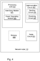
- the network node 110 comprises the following arrangement depicted in Figure 4 .
- the network node 110 operates one or more cells and is normally configured to transmit the CRS in a first power mode.
- the network node 110 comprises a radio circuitry 401 to communicate with UEs 120, a communication circuitry 402 to communicate with other network nodes and a processing unit 403.
- the network node 110 is configured to, e.g. by means of an identifying module 404 being configured to, identify a first cell 130 that is not actively serving any UEs 120.
- the network node 110 is further configured to, or comprises a power regulating module 405 configured to, reduce power of the CRS in the first cell 130 in relation to the first power mode, when a first cell is identified not to actively serve any UEs 120.
- the network node 110 may further be configured to, e.g. by means of a sending circuitry 406 being configured to, send information about the CRS power mode and the number of actively served UEs 120 to neighbouring network nodes 111.
- the means to send information about the CRS power mode and the number of connected UEs 120 to neighbouring network nodes 120 may be an X2 interface.
- the sending circuit 406 may be comprised in the communication circuitry 402.
- the network node 110 may be configured to, e.g. by means of a receiving circuitry 407 being configured to, receive information about the CRS power mode and number of actively served UEs 120 in neighbouring cells. The information is received from the neighboring network nodes 111.
- the receiving circuit 407 may be comprised in the communication circuitry 402.
- the network node 110 may further be configured to, or may comprise the identifying module 404 further being configured to, identify a second cell 131, which cell 131 is actively serving at least one UE 120 and is neighbouring a cell 132 where the number actively served UEs 120 exceeds a first threshold.
- the network node is configured to, or comprises the power regulating unit 405 further being configured to, increase the CRS power in the second cell 131 in relation to the first power mode when the number of actively served UEs 120 in the neighboring cell 132 exceeds the first threshold.
- the network node 110 may further be configured to, or may comprise the power regulating unit 405 further being configured to reduce and/or increase the CRS power using a hysteresis function.
- the network node 110 may not switch power mode immediately when the number of actively served UEs 120 changes, but will remain in one power mode for a certain amount of time after the change of actively served UEs 120 has taken place.
- the embodiments herein for managing power of Cell Reference Symbols, may be implemented through one or more processors, such as the processing unit 403 in the network node 110 depicted in Figure 4 , together with computer program code for performing the functions and actions of the embodiments herein.
- the program code mentioned above may also be provided as a computer program product, for instance in the form of a data carrier carrying computer program code for performing the embodiments herein when being loaded into the in the network node 110.
- One such carrier may be in the form of a CD ROM disc. It is however feasible with other data carriers such as a memory stick.
- the computer program code may furthermore be provided as pure program code on a server and downloaded to the network node 110.
- the identifying module 404 and power regulating module 405 described above may refer to a combination of analog and digital circuits, and/or one or more processors configured with software and/or firmware, e.g. stored in the memory 408, that when executed by the one or more processors such as the processing unit 403 as described above.
- processors as well as the other digital hardware, may be included in a single Application-Specific Integrated Circuitry (ASIC), or several processors and various digital hardware may be distributed among several separate components, whether individually packaged or assembled into a system-on-a-chip (SoC).
- ASIC Application-Specific Integrated Circuitry
- SoC system-on-a-chip
- the network node 110 may further comprise a memory 408 comprising one or more memory units.
- the memory 409 is arranged to be used to store obtained information, measurements, data, configurations, schedulings, and applications to perform the methods herein when being executed in the network node 110.
Description
- Embodiments herein relate to a network node and a method therein. In particular, it relates to a method for managing power of Cell Reference Symbols.
- Communication devices such as User Equipments (UEs) are enabled to communicate wirelessly in a cellular communications network or wireless communication system, sometimes also referred to as a cellular radio system or cellular networks. The communication may be performed e.g. between two UEs, between a UE and a regular telephone and/or between a UE and a server via a Radio Access Network (RAN) and possibly one or more core networks, comprised within the cellular communications network.
- UEs may further be referred to as wireless terminals, mobile terminals and/or mobile stations, mobile telephones, cellular telephones, laptops, tablet computers or surf plates with wireless capability, just to mention some further examples. The UEs in the present context may be, for example, portable, pocket-storable, hand-held, computer-comprised, or vehicle-mounted mobile devices, enabled to communicate voice and/or data, via the RAN, with another entity, such as another wireless terminal or a server.
- The cellular communications network covers a geographical area which is divided into cell areas, wherein each cell area being served by a network node. A cell is the geographical area where radio coverage is provided by the network node.
- The network node may further control several transmission points, e.g. having Radio Units (RRUs). A cell can thus comprise one or more network nodes each controlling one or more transmission/reception points. A transmission point, also referred to as a transmission/reception point, is an entity that transmits and/or receives radio signals. The entity has a position in space, e.g. an antenna. A network node is an entity that controls one or more transmission points. The network node may e.g. be a base station such as a Radio Base Station (RBS), eNB, eNodeB, NodeB, B node, or BTS (Base Transceiver Station), depending on the technology and terminology used. The base stations may be of different classes such as e.g. macro eNodeB, home eNodeB or pico base station, based on transmission power and thereby also cell size.
- Further, each network node may support one or several communication technologies. The network nodes communicate over the air interface operating on radio frequencies with the UEs within range of the network node. In the context of this disclosure, the expression Downlink (DL) is used for the transmission path from the base station to the mobile station. The expression Uplink (UL) is used for the transmission path in the opposite direction i.e. from the UE to the base station.
- In 3rd Generation Partnership Project (3GPP) Long Term Evolution (LTE), base stations, which may be referred to as eNodeBs or even eNBs, may be directly connected to one or more core networks. In LTE the cellular communication network is also referred to as E-UTRAN.
- An E-UTRAN cell is defined by certain signals which are broadcasted from the eNB. These signals contain information about the cell which can be used by UEs in order to connect to the network through the cell. The signals comprise reference and synchronization signals which the UE uses to find frame timing and physical cell identification as well as system information which comprises parameters relevant for the whole cell.
- A UE needing to connect to the network must thus first detect for a suitable cell, as defined in 3GPP TS 36.304 v11.5.0. This is performed by measuring on received reference signals sent by neighboring cells, also referred to as "listening" for a suitable cell. The suitable cell is commonly the cell with best quality of signal. Listening for a suitable cell may comprise searching for synchronization signals transmitted from the network node in an OFDM subframe. When a suitable cell is found the UE performs random access, according to a system information for the cell. This is done in order to transmit a Radio Resource Control (RRC) connection setup request to the network node. Assuming the random access procedure succeeds and the network node receives the request, the network node will either answer with an RRC connection setup message, which acknowledges the UEs request and tells it to move into RRC connected state, or an RRC connection reject, which tells the UE that it may not connect to the cell. In RRC connected state the parameters necessary for communication between the network node and the UE are known to both entities and a data transfer between the two entities is enabled.
- To facilitate handover to other cells, each network node may store cell identities that are supported by the other network nodes in an address database, in order to know how to contact the network node of potential target cells for handover. Each network node serving a cell typically stores in the data base which cells it has neighbor relations to, i.e. which of the cells in the area UEs often perform handover to. The cell's neighbor relations will hereafter be referred to as the cell's "neighbor relation list".
- Cell specific Reference Signals (CRS) are UE known symbols that are inserted in a Resource Element (RE) of a subframe of an Orthogonal Frequency-Division Multiplexing (OFDM) time and frequency grid and broadcasted by the network node. Each RE has an extension in the frequency domain corresponding to an OFDM sub carrier and an extension in the time-domain corresponding to an OFDM symbol interval.
- The CRS are used by the UE for downlink channel estimation. Channel estimation is used for demodulation of downlink data both when the UE is in RRC connected state and is receiving user data and when the UE is in RRC idle state and is reading system information. Due to the latter use case, the CRSs must be transmitted even from cells which do not have any UEs in RRC connected state since the eNB cannot know whether a UE wants to access the network until it performs random access. Downlink cell specific reference signals are inserted within the first and third last OFDM symbol of each slot with a frequency domain spacing of six sub-carriers. A slot is a time period of the OFDM time and frequency grid, which is usually 0.5 msec long. A problem with the known technology is therefore that cells without any UEs in RRC connected state still consume power due to CRS broadcasting.
- In case several antennas are used by the network node for transmitting and each antenna is representing a cell, each antenna has to transmit a unique reference signal in order for the UE to connect to that specific cell. When one antenna transmits, the other antennas have to be silent in order not to interfere with the first antennas reference signal. To reduce the interference of reference signals between the cells, the position of the CRS is usually shifted in frequency between the cells. The CRS can be shifted between 0 ― 5 sub carriers, each sub carrier corresponding to a frequency shift of 15 kHz for LTE. The cell specific frequency shift can be derived from the physical Cell Identity (Cell ID) which is signaled to the UE by selection of appropriate Primary Synchronization Channel (PSCH) and Secondary Synchronization Channel (SSCH).
- Although this solution reduces the interference of reference symbols between cells, it has the problem that the reference symbols of one cell will disturb Physical Downlink Shared Channel (PDSCH) and Physical Downlink Control Channel (PDCCH) symbols of neighboring cells.
- Hence, even though cells do not have any UEs in RRC connected state, disturbance may impact UE DL throughput in neighboring cells. This will especially be the case when the UE is in and/or close to borders between cells.
-
US 2009/0111499 A1 discloses a method for modifying pilot power for a home base station router based on user demand. The home base station router determines whether any mobile units are camped on the home base station router. If no mobile units are camped on the home base station router, the home base station router may set the pilot signal transmission power to a predetermined minimum level. -
US 2009/0280819 A1 discloses a method for managing femto cell signaling. The presence or absence of a UE in the femto cell is determined. When a UE is present a pilot signal power is increased from a first power level to a second power level. When the UE detaches from the femto cell, the pilot signal power level is reduced from the second power level to the first power level. -
US 5 898 682 A discloses a radio channel control apparatus used in CDMA cellular systems which is capable of changing cell size. A radio channel control section 370 transmits and receives to and from an adjacent base station uplink/downlink channel communication qualities measured by a communication channel transmit/receive section and a mobile station, respectively, compares them with predetermined lower and upper threshold values TI/Th, requests a pilot channel transmit section 350 to decrease and increase the transmission power level of a pilot signal if the threshold value TI is not reached and the threshold value Th is exceeded, respectively. - Reducing the power of the CRS may mitigate this problem. However, in order to access a cell the UE must be able to hear the CRS of the cell, i.e. the UE must be able to recognize and receive the CRS transmitted from the cell. Therefore reducing the power of the CRS also shrinks the size of the cell, since more distant UEs no longer will hear the CRS. Furthermore, the quality of the channel estimates used for demodulation decreases when the Signal to Interference Ratio (SINR) on the CRS decreases. Reducing the power of the CRS therefore causes degradation of cell edge performance. This degradation is further aggravated when the load in the network increases, especially if the data is transmitted with higher power than the CRS, which is usually the case when the effect of CRS interference is to be reduced.
- It is therefore an object of embodiments herein to enhance the performance in a wireless communications network.
- According to a first aspect of embodiments herein, the object is achieved by a method according to
claim 1. - According to a second aspect of embodiments herein, the object is achieved by a network node according to claim 6.
- By reducing the power of the CRS in cells that do not serve any UEs in RRC connected mode, the power consumption and the interference from empty cells can be reduced, thereby enhancing the performance of cells that have UEs in RRC connected mode. In a non-loaded system, reducing the power of the reference symbols will reduce interference and increase single UE throughput when CRSs are shifted in the frequency domain.
- Examples of embodiments herein are described in more detail with reference to attached drawings in which:
- Figure 1
- is a schematic block diagram illustrating embodiments of a wireless communications network.
- Figure 2
- is a schematic block diagram illustrating embodiments of an OFDM subframe.
- Figure 3
- is a flowchart depicting embodiments of a method in a network node.
- Figure 4
- is a schematic block diagram illustrating embodiments of a network node.
-
Figure 1 depicts an example of awireless communications network 100 according to a first scenario in which embodiments herein may be implemented. The wireless communications network100 is a wireless communication network such as an LTE, E-Utran, WCDMA, GSM network, any 3GPP cellular network, Wimax, or any cellular network or system. - The
wireless communications network 100 comprises a plurality of network nodes whereof two, afirst network node 110 and asecond network node 111 are depicted inFigure 1 . Thefirst network node 110 and thesecond network node 111 are network nodes which each may be a transmission point such as a radio base station, for example an eNB, an eNodeB, or an Home Node B, an Home eNode B or any other network node capable to serve a wireless terminal such as UE or a machine type communication device in a wireless communications network. Thefirst network node 110 and thesecond network node 111 each serves a plurality ofcells - The
wireless communications network 100 comprises aUE 120. Thefirst network node 110 and thesecond network node 111 may each be a transmission point for thewireless terminal 120. TheUE 120 is within radio range of thefirst network node 110 and thesecond network node 111, this means that it can hear signals from thefirst network node 110 and thesecond network node 111. - The
UE 120 may e.g. be a wireless terminal, a wireless device, a mobile wireless terminal or a wireless terminal, a mobile phone, a computer such as e.g. a laptop, a Personal Digital Assistant (PDA) or a tablet computer, sometimes referred to as a surf plate, with wireless capability, or any other radio network units capable to communicate over a radio link in a wireless communications network. Please note the term wireless terminal used in this document also covers other wireless devices such as Machine to machine (M2M) devices. -
Figure 2 shows an exemplary downlink OFDM time and frequency grid, which is also referred to as an OFDM subframe. Each subframe comprises two slots. Each slot comprising a number of resource elements (RE) 201 extending both in the time domain (x-axis) and in the frequency domain (z-axis). Each RE's 201 extension in the frequency domain is referred to as a sub-carrier whereas the extension in the time domain is referred to as an OFDM symbol. As can be seen infigure 2 , the first OFDM symbol comprises control signaling and CRS which carries the necessary information about thenetwork node 110 to allow theUE 120 to connect to it. The control signaling is located in the beginning of each subframe, also known as the control region of the subframe, and spans the full bandwith of the subframe.Figure 2 shows an exemplary size of a normal control region of three OFDM symbols, the size of the control region may however be dynamically adjusted according to the current traffic situation. - The CRS are used by the
UE 120 for downlink channel estimation. Channel estimation is used for determining the demodulation of downlink data both when theUE 120 is in RRC connected state and is receiving user data and when theUE 120 is in RRC idle state and is reading system information. Downlink CRS are inserted within the first and third last OFDM symbol of each slot with a frequency domain spacing of six sub-carriers. - The subframe also comprises data symbols used for transmitting user data between the
network node 110 and theUE 120. The data symbols are situated in the region following the control region, which is also referred to as the data region. - Example of embodiments of a method in the
network node 110 for managing power of CRS, will now be described with reference to a flowchart depicted inFigure 3 . Thenetwork node 110 operates one or more cells and is configured to transmit the CRS in a first power mode during operation. This relates to normal operation. The first power mode may also be referred to as the normal power mode which is used when the at least one cell of thenetwork node 110 is serving at least oneUE 120 in RRC connected mode. In this power mode CRS and data symbols are transmitted with the same power, i.e. the power difference between the CRS and the data symbols is zero or almost zero. - The method comprises the following actions, which actions may be taken in any suitable order. Dashed lines of a box in
Figure 3 indicate that this action is not mandatory. - The
network node 110 identifies afirst cell 130 which is not actively serving anyUEs 120 in RRC connected mode. When the cell is not actively serving anyUEs 120, the cell is referred to as an empty cell. - The cell is not actively serving any
UEs 120 when thenetwork node 110 has not sent or received any messages to/from anyUEs 120 in the cell within a predetermined time, and/or when the cell does not have anyUEs 120 in RRC connected mode. - The cell may switch from not actively serving any
UEs 120 to actively serving UEs in case of certain events. Events that trigger a switch may e.g. be that thenetwork node 110 sends a page message in thecell 130, receives a random access preamble in thecell 130 or sends a random access response in thecell 130. It may further be triggered when the network node sends/receives Common Control Channel messages, Dedicated Control Channel messages and/or Dedicated Traffic Channel messages in thecell 130. - When the
network node 110 has identified afirst cell 130 which is not actively serving anyUEs 120, i.e. anempty cell 130, thenetwork node 110 reduces the power of the CRS in thefirst cell 130 in relation to the first power mode. This reduced power mode may also be referred to as low power mode. By reducing the power of the CRS to a power level lower than the power level of the data symbols, the overall interference of the CRS from theempty cell 130 is reduced. - The reduced CRS power is applied on CRS which are sent on any OFDM symbol of a subframe, except the first OFDM symbol of the subframe. By applying the reduced CRS power on all the OFDM symbols except the first OFDM symbol, the interference by the CRS is reduced while at the same
time allowing UEs 120 to hear the CRS from theempty cell 130. - The
network node 110 holds the reduced CRS power as long as thecell 130 is determined not to actively serve anyUEs 120. - The CRS power may further be adapted in several levels. Possible values for the reduced power levels may be e.g. -3, -2, -1 dB compared to the other symbols, thereby allowing a reduction of power in three steps. However, other and/or further power levels may also be used.
- The power difference may be signaled to the
UE 120 in the system information where it may be used to improve the demodulation performance for modulation types which carry information in the amplitude domain. The modulation scheme used may be e.g. be 16QAM, 64QAM and/or any other modulation schemes which carries information in the amplitude domain. - In a further embodiment a hysteresis function may be applied when changing CRS power level, thereby avoiding unnecessary switching between the power modes when the
cell 130 is switching from not actively serving anyUEs 120 to actively serving UEs very quickly. - The
network node 110 may further send information about CRS power and the number of RRC connectedUEs 120 of each cell, to neighboring cells listed in a neighbor relation list. The neighboring cells may be connected to the same or todifferent network nodes 111. The information may be sent via an X2 interface when a neighboring cell is served by another network node 111. In a further embodiment the information may be sent over a S1 interface via a Mobility Management Entity (MME). - When the
UE 120 wants to connect to anetwork node 110, it measures the average Received CRS Power (RSRP) from each cell it can hear, and uses that information to decide which of the cells is suitable to connect to. The RSRP may also be used for connected state mobility, where thenetwork node 110 uses layer 3 measurement reports from theUE 120 sent on the uplink shared channel to support handover decisions. Such a report may for example state that theUE 120 is about to move out of coverage of its current serving cell. However, 3GPP offers a set of tools and mechanisms which thenetwork node 110 can configure in theUE 120 in order to get other reports which are relevant and needed. One example is the A3 event in which thenetwork node 110 configures theUE 120 to send the RSRP of both the serving cell and neighbor cells should the neighbor RSRP become sufficiently strong compared to the serving cell. This information may then be forwarded to the neighboring cells by thenetwork node 110. - In some embodiments the
network node 110 also receives information about the CRS power mode and number of actively servedUEs 120 in neighboring cells. The information may be received from neighboringnetwork nodes 111. When the information is received from a neighboringnetwork node 111 it may be received via the X2 interface. - The information may, in one example, also be received over the S1 interface via the MME.
- The information may be used to allow the
network node 110 to configure Cell Individual Offsets (CIO) with both positive and negative values. TheUE 120 may add the CIO for a given cell to the measured RSRP of that cell, in order to compensate for the low CRS power level of that cell. By doing so theUE 120 may connect to another cell, e.g. theempty cell 130, even though the RSRP is lower for theempty cell 130 than for anothercell UEs 120. CIO can be configured both in IDLE mode, where it is broadcasted in System Information Blocks (SIB), and in connected mode, where it is sent in a dedicated RRC configuration to eachUE 120. - When the network node has received the information about neighboring cells it may use this information to identify a
second cell 131, whichcell 131 is actively serving at least oneUE 120 and is neighbouring acell 132 where the number of actively servedUEs 120 exceeds a first threshold, based on the information received inaction 304. - When the network node has indentified a
second cell 131 according toaction 305, it may increase the power of the CRS in thesecond cell 131 in relation to the first power mode. By increasing the power of the CRS in thesecond cell 131, UEs located in the surrounding cells are able to more easily detect the second cell in order to connect to it. - The CRS power may also be increased in several levels. Possible values for the increased power levels may be e.g. 1.77 and 3 dB compared to the other symbols, thereby allowing an increase of power in two steps. However, other and/or further power levels may also be used.
- By increasing the power of the CRS in the
second cell 131, UEs located in the surrounding cells are able to more easily detect the second cell in order to connect to it. - To perform the method actions for managing power of Cell Reference Symbols, (CRS) described above in relation to
Figure 2 , thenetwork node 110 comprises the following arrangement depicted inFigure 4 . As mentioned above thenetwork node 110 operates one or more cells and is normally configured to transmit the CRS in a first power mode. - The
network node 110 comprises aradio circuitry 401 to communicate withUEs 120, acommunication circuitry 402 to communicate with other network nodes and aprocessing unit 403. - The
network node 110 is configured to, e.g. by means of an identifyingmodule 404 being configured to, identify afirst cell 130 that is not actively serving anyUEs 120. Thenetwork node 110 is further configured to, or comprises apower regulating module 405 configured to, reduce power of the CRS in thefirst cell 130 in relation to the first power mode, when a first cell is identified not to actively serve anyUEs 120. - In some embodiments herein, the
network node 110 may further be configured to, e.g. by means of a sending circuitry 406 being configured to, send information about the CRS power mode and the number of actively servedUEs 120 to neighbouringnetwork nodes 111. In one embodiment the means to send information about the CRS power mode and the number of connectedUEs 120 to neighbouringnetwork nodes 120 may be an X2 interface. The sending circuit 406 may be comprised in thecommunication circuitry 402. - In a further embodiment the
network node 110 may be configured to, e.g. by means of a receiving circuitry 407 being configured to, receive information about the CRS power mode and number of actively servedUEs 120 in neighbouring cells. The information is received from the neighboringnetwork nodes 111. The receiving circuit 407 may be comprised in thecommunication circuitry 402. - The
network node 110 may further be configured to, or may comprise the identifyingmodule 404 further being configured to, identify asecond cell 131, whichcell 131 is actively serving at least oneUE 120 and is neighbouring acell 132 where the number actively servedUEs 120 exceeds a first threshold. - In a further embodiment the network node is configured to, or comprises the
power regulating unit 405 further being configured to, increase the CRS power in thesecond cell 131 in relation to the first power mode when the number of actively servedUEs 120 in the neighboringcell 132 exceeds the first threshold. - In order to reduce unnecessary switching between the power modes, the
network node 110 may further be configured to, or may comprise thepower regulating unit 405 further being configured to reduce and/or increase the CRS power using a hysteresis function. By using a hysteresis function thenetwork node 110 may not switch power mode immediately when the number of actively servedUEs 120 changes, but will remain in one power mode for a certain amount of time after the change of actively servedUEs 120 has taken place. - The embodiments herein for managing power of Cell Reference Symbols, (CRS) may be implemented through one or more processors, such as the
processing unit 403 in thenetwork node 110 depicted inFigure 4 , together with computer program code for performing the functions and actions of the embodiments herein. The program code mentioned above may also be provided as a computer program product, for instance in the form of a data carrier carrying computer program code for performing the embodiments herein when being loaded into the in thenetwork node 110. One such carrier may be in the form of a CD ROM disc. It is however feasible with other data carriers such as a memory stick. The computer program code may furthermore be provided as pure program code on a server and downloaded to thenetwork node 110. - Those skilled in the art will also appreciate that the identifying
module 404 andpower regulating module 405 described above may refer to a combination of analog and digital circuits, and/or one or more processors configured with software and/or firmware, e.g. stored in thememory 408, that when executed by the one or more processors such as theprocessing unit 403 as described above. One or more of these processors, as well as the other digital hardware, may be included in a single Application-Specific Integrated Circuitry (ASIC), or several processors and various digital hardware may be distributed among several separate components, whether individually packaged or assembled into a system-on-a-chip (SoC). - The
network node 110 may further comprise amemory 408 comprising one or more memory units. The memory 409 is arranged to be used to store obtained information, measurements, data, configurations, schedulings, and applications to perform the methods herein when being executed in thenetwork node 110. - When using the word "comprise" or "comprising" it shall be interpreted as nonlimiting, i.e. meaning "consist at least of".
- The embodiments herein are not limited to the above described preferred embodiments. The above embodiments should not be taken as limiting the scope of the invention, which is defined by the appending claims.
Claims (10)
- A method performed by a network node (110) for managing power of Cell Reference Symbols, CRS, wherein the CRS is a reference symbol in an Orthogonal Frequency-Division Multiplexing, OFDM subframe, the symbol being known by a User Equipment, UE, wherein the subframe comprises a control region and a data region, wherein the network node (110) operates one or more cells (130, 131, 132) and wherein the network node (110) is configured to transmit the CRS in a first power mode, wherein in the first power mode the CRS and data symbols are transmitted with the same power, the method comprising:
when a first cell (130) is identified, which first cell (130) is not actively serving any UEs (120), reducing (302) power of the CRS in the first cell (130) in relation to the first power mode, characterized in that the reduced CRS power is applied on CRS which are sent on any OFDM symbol of the subframe, except the first OFDM symbol of the subframe, wherein the reduced CRS power is applied on the CRS in the data region of the subframe and wherein the first OFDM symbol is located in the control region of the subframe. - The method according to claim 1, wherein the method further comprises:
sending (303) information about the CRS power and a number of RRC connected UEs (120) to one or more neighbouring network nodes (111). - The method according to claim 2, wherein the information is sent via an X2 interface.
- The method according to any of the claims 1-3, wherein, when the first cell (130) is determined to actively serve at least one UE (120), the method further comprises:receiving (304), from neighbouring network nodes (111), information about the CRS power mode and number of actively served UEs (120) in neighbouring cells,identifying (305) a second cell (131), which cell (131) is actively serving at least one UE (120) in and is neighbouring a cell (132) where the number of actively served UEs (120) exceeds a first threshold,increasing (306) the power of the CRS in the second cell (131) in relation to the first power mode.
- The method according to claim 4, wherein reducing and increasing the CRS power is performed using a hysteresis function.
- A network node (110) for performing the method for managing power of Cell Reference Symbols, CRSs, wherein the CRS is a reference symbol in an Orthogonal Frequency-Division Multiplexing, OFDM subframe, the symbol being known by a User Equipment, UE, wherein the subframe comprises a control region and a data region, wherein the network node (110) operates one or more cells (130, 131, 132) and the network node (110) is configured to transmit the CRS in a first power mode, wherein in the first power mode the CRS and data symbols are transmitted with the same power,, the network node (110) further being configured to:identify a first cell (130) that is not actively serving any UEs (120); andreduce power of the CRS in the first cell (130) in relation to the first power mode, characterized in that the network node (110) is configured to apply the reduced CRS power on CRS which are sent on any OFDM symbol of the subframe, except the first OFDM symbol of the subframe, wherein the reduced CRS power is applied on the CRS in the data region of the subframe and wherein the first OFDM symbol is located in the control region of the subframe..
- The network node (110) according to claim 6, wherein the network node (110) further is configured to:
send information about the CRS power mode and a number of actively served UEs (120) to one or more neighbouring network nodes (111). - The network node (110) according to claim 7, wherein means to send information about the CRS power mode and the number of actively served UEs (120) to neighbouring network nodes (111) is an X2 interface.
- The network node (110) according to any of the claims 6-8, wherein the network node (110) further is configured to:receive, from neighbouring network nodes (111), information about the CRS power mode and number of actively served UEs (120) in neighbouring cells,identify a second cell (131), which cell (131) is actively serving at least one UE (120) and is neighbouring a cell (132) where the number of actively served UEs (120) exceeds a first threshold,increase the CRS power in the second cell (131) in relation to the first power mode.
- The network node (110) according to claim 9, wherein the network node (110) further is configured to:
reduce and increase the CRS power using a hysteresis function.
Priority Applications (1)
| Application Number | Priority Date | Filing Date | Title |
|---|---|---|---|
| EP17199124.3A EP3294012B1 (en) | 2014-08-28 | 2014-08-28 | Network node and method for managing power of cell reference symbols |
Applications Claiming Priority (3)
| Application Number | Priority Date | Filing Date | Title |
|---|---|---|---|
| EP14781323.2A EP3187008B1 (en) | 2014-08-28 | 2014-08-28 | Network node and method for managing power of cell reference symbols |
| PCT/SE2014/050993 WO2016032380A1 (en) | 2014-08-28 | 2014-08-28 | Network node and method for managing power of cell reference symbols |
| EP17199124.3A EP3294012B1 (en) | 2014-08-28 | 2014-08-28 | Network node and method for managing power of cell reference symbols |
Related Parent Applications (2)
| Application Number | Title | Priority Date | Filing Date |
|---|---|---|---|
| EP14781323.2A Division-Into EP3187008B1 (en) | 2014-08-28 | 2014-08-28 | Network node and method for managing power of cell reference symbols |
| EP14781323.2A Division EP3187008B1 (en) | 2014-08-28 | 2014-08-28 | Network node and method for managing power of cell reference symbols |
Publications (2)
| Publication Number | Publication Date |
|---|---|
| EP3294012A1 EP3294012A1 (en) | 2018-03-14 |
| EP3294012B1 true EP3294012B1 (en) | 2021-10-27 |
Family
ID=51662292
Family Applications (2)
| Application Number | Title | Priority Date | Filing Date |
|---|---|---|---|
| EP14781323.2A Active EP3187008B1 (en) | 2014-08-28 | 2014-08-28 | Network node and method for managing power of cell reference symbols |
| EP17199124.3A Active EP3294012B1 (en) | 2014-08-28 | 2014-08-28 | Network node and method for managing power of cell reference symbols |
Family Applications Before (1)
| Application Number | Title | Priority Date | Filing Date |
|---|---|---|---|
| EP14781323.2A Active EP3187008B1 (en) | 2014-08-28 | 2014-08-28 | Network node and method for managing power of cell reference symbols |
Country Status (9)
| Country | Link |
|---|---|
| US (3) | US10764839B2 (en) |
| EP (2) | EP3187008B1 (en) |
| CN (2) | CN106576306B (en) |
| DK (1) | DK3187008T3 (en) |
| ES (1) | ES2660040T3 (en) |
| HU (1) | HUE036714T2 (en) |
| PL (1) | PL3187008T3 (en) |
| PT (1) | PT3187008T (en) |
| WO (1) | WO2016032380A1 (en) |
Families Citing this family (2)
| Publication number | Priority date | Publication date | Assignee | Title |
|---|---|---|---|---|
| CN111385861B (en) * | 2018-12-29 | 2023-06-23 | 普天信息技术有限公司 | Method and device for coordinating downlink traffic channel interference |
| CN115134020A (en) * | 2021-03-24 | 2022-09-30 | 中兴通讯股份有限公司 | Method and device for compensating reference signal received power and storage medium |
Citations (1)
| Publication number | Priority date | Publication date | Assignee | Title |
|---|---|---|---|---|
| US20110170496A1 (en) * | 2010-01-11 | 2011-07-14 | Research In Motion Limited | Control Channel Interference Management and Extended PDCCH for Heterogeneous Network |
Family Cites Families (21)
| Publication number | Priority date | Publication date | Assignee | Title |
|---|---|---|---|---|
| JP2803716B2 (en) | 1996-03-11 | 1998-09-24 | 日本電気株式会社 | Radio channel controller in CDMA cellular system |
| DE10331313B3 (en) * | 2003-07-10 | 2005-01-05 | Siemens Ag | Method for synchronizing a radio communication system divided into radio cells |
| US7515924B2 (en) | 2003-10-30 | 2009-04-07 | Qualcomm Incorporated | Method and module for operating independently of a remote terminal if an incoming pilot signal is not detected within a time period and enabling a pilot signal transmission |
| US8989084B2 (en) * | 2005-10-14 | 2015-03-24 | Qualcomm Incorporated | Methods and apparatus for broadcasting loading information corresponding to neighboring base stations |
| EP2165438B1 (en) * | 2007-06-26 | 2019-02-20 | Telefonaktiebolaget LM Ericsson (publ) | Device and method for transmitting cell offset in telecommunication system |
| US9066306B2 (en) * | 2007-09-21 | 2015-06-23 | Qualcomm Incorporated | Interference management utilizing power control |
| US20090111499A1 (en) | 2007-10-24 | 2009-04-30 | Peter Bosch | Method of modifying pilot power for a home base station router based on user demand |
| US8626223B2 (en) * | 2008-05-07 | 2014-01-07 | At&T Mobility Ii Llc | Femto cell signaling gating |
| CN101860867B (en) | 2009-04-09 | 2013-05-15 | 电信科学技术研究院 | Method, system and equipment for optimizing cell reference symbols |
| WO2011100857A1 (en) * | 2010-02-17 | 2011-08-25 | Telefonaktiebolaget L M Ericsson (Publ) | Method and apparatus for improving demodulation performance using demodulation reference signals power boosting |
| US9264954B2 (en) * | 2010-04-28 | 2016-02-16 | Qualcomm Incorporated | Neighbor relation information management |
| JP5644028B2 (en) | 2010-05-27 | 2014-12-24 | 京セラ株式会社 | Wireless base station, wireless communication system, and wireless communication method |
| US9300450B2 (en) * | 2011-02-09 | 2016-03-29 | Telefonaktiebolaget L M Ericsson (Publ) | Distribution of cell-common downlink signals in a hierarchical heterogeneous cell deployment |
| BR112013018711A2 (en) * | 2011-02-09 | 2016-10-25 | Ericsson Telefon Ab L M | dot-dependent feature symbol setting in a wireless cell |
| EP3148248B1 (en) * | 2011-06-21 | 2022-04-27 | Telefonaktiebolaget LM Ericsson (publ) | Methods, apparatuses and computer-readable medium for performing non-si measurements in a wireless network |
| US9179396B2 (en) * | 2011-11-09 | 2015-11-03 | Telefonaktiebolaget L M Ericsson (Publ) | Almost-blank subframe configuration detection in heterogeneous networks |
| US9219994B2 (en) * | 2011-11-09 | 2015-12-22 | Lg Electronics Inc. | Methods for transmitting and receiving downlink data in MBSFN subframe and apparatuses thereof |
| US9867163B2 (en) * | 2012-07-12 | 2018-01-09 | Qualcomm Incorporated | Methods and apparatus for power saving in broadcasting carrier information |
| US9160485B2 (en) * | 2012-12-03 | 2015-10-13 | Lg Electronics Inc. | Method and apparatus for encoding transport block |
| JP5723423B2 (en) * | 2013-08-01 | 2015-05-27 | 株式会社Nttドコモ | Radio base station apparatus and transmission power determination method |
| CN105684487B (en) * | 2013-11-01 | 2020-09-04 | 三菱电机株式会社 | Communication system |
-
2014
- 2014-08-28 WO PCT/SE2014/050993 patent/WO2016032380A1/en active Application Filing
- 2014-08-28 EP EP14781323.2A patent/EP3187008B1/en active Active
- 2014-08-28 DK DK14781323.2T patent/DK3187008T3/en active
- 2014-08-28 EP EP17199124.3A patent/EP3294012B1/en active Active
- 2014-08-28 CN CN201480081633.8A patent/CN106576306B/en active Active
- 2014-08-28 HU HUE14781323A patent/HUE036714T2/en unknown
- 2014-08-28 PL PL14781323T patent/PL3187008T3/en unknown
- 2014-08-28 US US15/507,528 patent/US10764839B2/en active Active
- 2014-08-28 ES ES14781323.2T patent/ES2660040T3/en active Active
- 2014-08-28 PT PT147813232T patent/PT3187008T/en unknown
- 2014-08-28 CN CN202010960552.2A patent/CN112423377B/en active Active
-
2020
- 2020-07-23 US US16/936,811 patent/US11304153B2/en active Active
-
2022
- 2022-03-04 US US17/687,287 patent/US11601894B2/en active Active
Patent Citations (1)
| Publication number | Priority date | Publication date | Assignee | Title |
|---|---|---|---|---|
| US20110170496A1 (en) * | 2010-01-11 | 2011-07-14 | Research In Motion Limited | Control Channel Interference Management and Extended PDCCH for Heterogeneous Network |
Also Published As
| Publication number | Publication date |
|---|---|
| US10764839B2 (en) | 2020-09-01 |
| DK3187008T3 (en) | 2018-03-26 |
| EP3187008B1 (en) | 2017-12-27 |
| US11304153B2 (en) | 2022-04-12 |
| US20200359337A1 (en) | 2020-11-12 |
| WO2016032380A1 (en) | 2016-03-03 |
| EP3294012A1 (en) | 2018-03-14 |
| US20220191808A1 (en) | 2022-06-16 |
| CN112423377A (en) | 2021-02-26 |
| CN112423377B (en) | 2023-11-28 |
| ES2660040T3 (en) | 2018-03-20 |
| CN106576306B (en) | 2020-10-16 |
| PT3187008T (en) | 2018-01-17 |
| EP3187008A1 (en) | 2017-07-05 |
| CN106576306A (en) | 2017-04-19 |
| US11601894B2 (en) | 2023-03-07 |
| PL3187008T3 (en) | 2018-05-30 |
| HUE036714T2 (en) | 2018-07-30 |
| US20170289925A1 (en) | 2017-10-05 |
Similar Documents
| Publication | Publication Date | Title |
|---|---|---|
| US11616622B2 (en) | Network node and method for managing transmission of cell reference symbols | |
| US11233616B2 (en) | Network node and method in a wireless telecommunications network | |
| EP3210424B1 (en) | Handling handover of an ue in case cell specific reference signals interfer with a physical downlink control channel | |
| US10694474B2 (en) | Network node and method for managing transmit power | |
| US11601894B2 (en) | Network node and method for managing power of cell reference symbols | |
| EP3210327B1 (en) | Increasing robustness of handover singalling by increasing the aggregation level of control channel elements |
Legal Events
| Date | Code | Title | Description |
|---|---|---|---|
| PUAI | Public reference made under article 153(3) epc to a published international application that has entered the european phase |
Free format text: ORIGINAL CODE: 0009012 |
|
| STAA | Information on the status of an ep patent application or granted ep patent |
Free format text: STATUS: THE APPLICATION HAS BEEN PUBLISHED |
|
| AC | Divisional application: reference to earlier application |
Ref document number: 3187008 Country of ref document: EP Kind code of ref document: P |
|
| AK | Designated contracting states |
Kind code of ref document: A1 Designated state(s): AL AT BE BG CH CY CZ DE DK EE ES FI FR GB GR HR HU IE IS IT LI LT LU LV MC MK MT NL NO PL PT RO RS SE SI SK SM TR |
|
| STAA | Information on the status of an ep patent application or granted ep patent |
Free format text: STATUS: REQUEST FOR EXAMINATION WAS MADE |
|
| 17P | Request for examination filed |
Effective date: 20180912 |
|
| RBV | Designated contracting states (corrected) |
Designated state(s): AL AT BE BG CH CY CZ DE DK EE ES FI FR GB GR HR HU IE IS IT LI LT LU LV MC MK MT NL NO PL PT RO RS SE SI SK SM TR |
|
| STAA | Information on the status of an ep patent application or granted ep patent |
Free format text: STATUS: EXAMINATION IS IN PROGRESS |
|
| 17Q | First examination report despatched |
Effective date: 20181128 |
|
| STAA | Information on the status of an ep patent application or granted ep patent |
Free format text: STATUS: EXAMINATION IS IN PROGRESS |
|
| GRAP | Despatch of communication of intention to grant a patent |
Free format text: ORIGINAL CODE: EPIDOSNIGR1 |
|
| STAA | Information on the status of an ep patent application or granted ep patent |
Free format text: STATUS: GRANT OF PATENT IS INTENDED |
|
| INTG | Intention to grant announced |
Effective date: 20210527 |
|
| GRAJ | Information related to disapproval of communication of intention to grant by the applicant or resumption of examination proceedings by the epo deleted |
Free format text: ORIGINAL CODE: EPIDOSDIGR1 |
|
| STAA | Information on the status of an ep patent application or granted ep patent |
Free format text: STATUS: EXAMINATION IS IN PROGRESS |
|
| GRAS | Grant fee paid |
Free format text: ORIGINAL CODE: EPIDOSNIGR3 |
|
| STAA | Information on the status of an ep patent application or granted ep patent |
Free format text: STATUS: GRANT OF PATENT IS INTENDED |
|
| GRAP | Despatch of communication of intention to grant a patent |
Free format text: ORIGINAL CODE: EPIDOSNIGR1 |
|
| INTC | Intention to grant announced (deleted) | ||
| GRAA | (expected) grant |
Free format text: ORIGINAL CODE: 0009210 |
|
| STAA | Information on the status of an ep patent application or granted ep patent |
Free format text: STATUS: THE PATENT HAS BEEN GRANTED |
|
| INTG | Intention to grant announced |
Effective date: 20210915 |
|
| AC | Divisional application: reference to earlier application |
Ref document number: 3187008 Country of ref document: EP Kind code of ref document: P |
|
| AK | Designated contracting states |
Kind code of ref document: B1 Designated state(s): AL AT BE BG CH CY CZ DE DK EE ES FI FR GB GR HR HU IE IS IT LI LT LU LV MC MK MT NL NO PL PT RO RS SE SI SK SM TR |
|
| REG | Reference to a national code |
Ref country code: GB Ref legal event code: FG4D |
|
| REG | Reference to a national code |
Ref country code: CH Ref legal event code: EP |
|
| REG | Reference to a national code |
Ref country code: AT Ref legal event code: REF Ref document number: 1443061 Country of ref document: AT Kind code of ref document: T Effective date: 20211115 |
|
| REG | Reference to a national code |
Ref country code: SE Ref legal event code: TRGR |
|
| REG | Reference to a national code |
Ref country code: DE Ref legal event code: R096 Ref document number: 602014080970 Country of ref document: DE |
|
| REG | Reference to a national code |
Ref country code: IE Ref legal event code: FG4D |
|
| REG | Reference to a national code |
Ref country code: NL Ref legal event code: FP |
|
| REG | Reference to a national code |
Ref country code: LT Ref legal event code: MG9D |
|
| REG | Reference to a national code |
Ref country code: AT Ref legal event code: MK05 Ref document number: 1443061 Country of ref document: AT Kind code of ref document: T Effective date: 20211027 |
|
| PG25 | Lapsed in a contracting state [announced via postgrant information from national office to epo] |
Ref country code: FI Free format text: LAPSE BECAUSE OF FAILURE TO SUBMIT A TRANSLATION OF THE DESCRIPTION OR TO PAY THE FEE WITHIN THE PRESCRIBED TIME-LIMIT Effective date: 20211027 Ref country code: BG Free format text: LAPSE BECAUSE OF FAILURE TO SUBMIT A TRANSLATION OF THE DESCRIPTION OR TO PAY THE FEE WITHIN THE PRESCRIBED TIME-LIMIT Effective date: 20220127 Ref country code: AT Free format text: LAPSE BECAUSE OF FAILURE TO SUBMIT A TRANSLATION OF THE DESCRIPTION OR TO PAY THE FEE WITHIN THE PRESCRIBED TIME-LIMIT Effective date: 20211027 Ref country code: RS Free format text: LAPSE BECAUSE OF FAILURE TO SUBMIT A TRANSLATION OF THE DESCRIPTION OR TO PAY THE FEE WITHIN THE PRESCRIBED TIME-LIMIT Effective date: 20211027 Ref country code: LT Free format text: LAPSE BECAUSE OF FAILURE TO SUBMIT A TRANSLATION OF THE DESCRIPTION OR TO PAY THE FEE WITHIN THE PRESCRIBED TIME-LIMIT Effective date: 20211027 |
|
| PG25 | Lapsed in a contracting state [announced via postgrant information from national office to epo] |
Ref country code: IS Free format text: LAPSE BECAUSE OF FAILURE TO SUBMIT A TRANSLATION OF THE DESCRIPTION OR TO PAY THE FEE WITHIN THE PRESCRIBED TIME-LIMIT Effective date: 20220227 Ref country code: PT Free format text: LAPSE BECAUSE OF FAILURE TO SUBMIT A TRANSLATION OF THE DESCRIPTION OR TO PAY THE FEE WITHIN THE PRESCRIBED TIME-LIMIT Effective date: 20220228 Ref country code: PL Free format text: LAPSE BECAUSE OF FAILURE TO SUBMIT A TRANSLATION OF THE DESCRIPTION OR TO PAY THE FEE WITHIN THE PRESCRIBED TIME-LIMIT Effective date: 20211027 Ref country code: NO Free format text: LAPSE BECAUSE OF FAILURE TO SUBMIT A TRANSLATION OF THE DESCRIPTION OR TO PAY THE FEE WITHIN THE PRESCRIBED TIME-LIMIT Effective date: 20220127 Ref country code: LV Free format text: LAPSE BECAUSE OF FAILURE TO SUBMIT A TRANSLATION OF THE DESCRIPTION OR TO PAY THE FEE WITHIN THE PRESCRIBED TIME-LIMIT Effective date: 20211027 Ref country code: HR Free format text: LAPSE BECAUSE OF FAILURE TO SUBMIT A TRANSLATION OF THE DESCRIPTION OR TO PAY THE FEE WITHIN THE PRESCRIBED TIME-LIMIT Effective date: 20211027 Ref country code: GR Free format text: LAPSE BECAUSE OF FAILURE TO SUBMIT A TRANSLATION OF THE DESCRIPTION OR TO PAY THE FEE WITHIN THE PRESCRIBED TIME-LIMIT Effective date: 20220128 Ref country code: ES Free format text: LAPSE BECAUSE OF FAILURE TO SUBMIT A TRANSLATION OF THE DESCRIPTION OR TO PAY THE FEE WITHIN THE PRESCRIBED TIME-LIMIT Effective date: 20211027 |
|
| REG | Reference to a national code |
Ref country code: DE Ref legal event code: R097 Ref document number: 602014080970 Country of ref document: DE |
|
| PG25 | Lapsed in a contracting state [announced via postgrant information from national office to epo] |
Ref country code: SM Free format text: LAPSE BECAUSE OF FAILURE TO SUBMIT A TRANSLATION OF THE DESCRIPTION OR TO PAY THE FEE WITHIN THE PRESCRIBED TIME-LIMIT Effective date: 20211027 Ref country code: SK Free format text: LAPSE BECAUSE OF FAILURE TO SUBMIT A TRANSLATION OF THE DESCRIPTION OR TO PAY THE FEE WITHIN THE PRESCRIBED TIME-LIMIT Effective date: 20211027 Ref country code: RO Free format text: LAPSE BECAUSE OF FAILURE TO SUBMIT A TRANSLATION OF THE DESCRIPTION OR TO PAY THE FEE WITHIN THE PRESCRIBED TIME-LIMIT Effective date: 20211027 Ref country code: EE Free format text: LAPSE BECAUSE OF FAILURE TO SUBMIT A TRANSLATION OF THE DESCRIPTION OR TO PAY THE FEE WITHIN THE PRESCRIBED TIME-LIMIT Effective date: 20211027 Ref country code: DK Free format text: LAPSE BECAUSE OF FAILURE TO SUBMIT A TRANSLATION OF THE DESCRIPTION OR TO PAY THE FEE WITHIN THE PRESCRIBED TIME-LIMIT Effective date: 20211027 Ref country code: CZ Free format text: LAPSE BECAUSE OF FAILURE TO SUBMIT A TRANSLATION OF THE DESCRIPTION OR TO PAY THE FEE WITHIN THE PRESCRIBED TIME-LIMIT Effective date: 20211027 |
|
| PLBE | No opposition filed within time limit |
Free format text: ORIGINAL CODE: 0009261 |
|
| STAA | Information on the status of an ep patent application or granted ep patent |
Free format text: STATUS: NO OPPOSITION FILED WITHIN TIME LIMIT |
|
| 26N | No opposition filed |
Effective date: 20220728 |
|
| PG25 | Lapsed in a contracting state [announced via postgrant information from national office to epo] |
Ref country code: AL Free format text: LAPSE BECAUSE OF FAILURE TO SUBMIT A TRANSLATION OF THE DESCRIPTION OR TO PAY THE FEE WITHIN THE PRESCRIBED TIME-LIMIT Effective date: 20211027 |
|
| PG25 | Lapsed in a contracting state [announced via postgrant information from national office to epo] |
Ref country code: SI Free format text: LAPSE BECAUSE OF FAILURE TO SUBMIT A TRANSLATION OF THE DESCRIPTION OR TO PAY THE FEE WITHIN THE PRESCRIBED TIME-LIMIT Effective date: 20211027 |
|
| PG25 | Lapsed in a contracting state [announced via postgrant information from national office to epo] |
Ref country code: MC Free format text: LAPSE BECAUSE OF FAILURE TO SUBMIT A TRANSLATION OF THE DESCRIPTION OR TO PAY THE FEE WITHIN THE PRESCRIBED TIME-LIMIT Effective date: 20211027 |
|
| REG | Reference to a national code |
Ref country code: CH Ref legal event code: PL |
|
| PG25 | Lapsed in a contracting state [announced via postgrant information from national office to epo] |
Ref country code: LU Free format text: LAPSE BECAUSE OF NON-PAYMENT OF DUE FEES Effective date: 20220828 Ref country code: LI Free format text: LAPSE BECAUSE OF NON-PAYMENT OF DUE FEES Effective date: 20220831 Ref country code: CH Free format text: LAPSE BECAUSE OF NON-PAYMENT OF DUE FEES Effective date: 20220831 |
|
| REG | Reference to a national code |
Ref country code: BE Ref legal event code: MM Effective date: 20220831 |
|
| PG25 | Lapsed in a contracting state [announced via postgrant information from national office to epo] |
Ref country code: IE Free format text: LAPSE BECAUSE OF NON-PAYMENT OF DUE FEES Effective date: 20220828 Ref country code: FR Free format text: LAPSE BECAUSE OF NON-PAYMENT OF DUE FEES Effective date: 20220831 |
|
| PG25 | Lapsed in a contracting state [announced via postgrant information from national office to epo] |
Ref country code: BE Free format text: LAPSE BECAUSE OF NON-PAYMENT OF DUE FEES Effective date: 20220831 |
|
| PGFP | Annual fee paid to national office [announced via postgrant information from national office to epo] |
Ref country code: NL Payment date: 20230826 Year of fee payment: 10 |
|
| PGFP | Annual fee paid to national office [announced via postgrant information from national office to epo] |
Ref country code: IT Payment date: 20230822 Year of fee payment: 10 Ref country code: GB Payment date: 20230828 Year of fee payment: 10 |
|
| PGFP | Annual fee paid to national office [announced via postgrant information from national office to epo] |
Ref country code: SE Payment date: 20230827 Year of fee payment: 10 Ref country code: DE Payment date: 20230829 Year of fee payment: 10 |
|
| PG25 | Lapsed in a contracting state [announced via postgrant information from national office to epo] |
Ref country code: HU Free format text: LAPSE BECAUSE OF FAILURE TO SUBMIT A TRANSLATION OF THE DESCRIPTION OR TO PAY THE FEE WITHIN THE PRESCRIBED TIME-LIMIT; INVALID AB INITIO Effective date: 20140828 |