EP3293971A1 - Verfahren zur nachführung eines bildausschnitts - Google Patents
Verfahren zur nachführung eines bildausschnitts Download PDFInfo
- Publication number
- EP3293971A1 EP3293971A1 EP17180948.6A EP17180948A EP3293971A1 EP 3293971 A1 EP3293971 A1 EP 3293971A1 EP 17180948 A EP17180948 A EP 17180948A EP 3293971 A1 EP3293971 A1 EP 3293971A1
- Authority
- EP
- European Patent Office
- Prior art keywords
- trailer
- motion vector
- determined
- image
- point
- Prior art date
- Legal status (The legal status is an assumption and is not a legal conclusion. Google has not performed a legal analysis and makes no representation as to the accuracy of the status listed.)
- Granted
Links
Images



Classifications
-
- G—PHYSICS
- G01—MEASURING; TESTING
- G01C—MEASURING DISTANCES, LEVELS OR BEARINGS; SURVEYING; NAVIGATION; GYROSCOPIC INSTRUMENTS; PHOTOGRAMMETRY OR VIDEOGRAMMETRY
- G01C11/00—Photogrammetry or videogrammetry, e.g. stereogrammetry; Photographic surveying
- G01C11/04—Interpretation of pictures
-
- B—PERFORMING OPERATIONS; TRANSPORTING
- B62—LAND VEHICLES FOR TRAVELLING OTHERWISE THAN ON RAILS
- B62D—MOTOR VEHICLES; TRAILERS
- B62D53/00—Tractor-trailer combinations; Road trains
-
- G—PHYSICS
- G01—MEASURING; TESTING
- G01B—MEASURING LENGTH, THICKNESS OR SIMILAR LINEAR DIMENSIONS; MEASURING ANGLES; MEASURING AREAS; MEASURING IRREGULARITIES OF SURFACES OR CONTOURS
- G01B11/00—Measuring arrangements characterised by the use of optical techniques
- G01B11/24—Measuring arrangements characterised by the use of optical techniques for measuring contours or curvatures
-
- G—PHYSICS
- G06—COMPUTING OR CALCULATING; COUNTING
- G06V—IMAGE OR VIDEO RECOGNITION OR UNDERSTANDING
- G06V20/00—Scenes; Scene-specific elements
- G06V20/50—Context or environment of the image
- G06V20/56—Context or environment of the image exterior to a vehicle by using sensors mounted on the vehicle
- G06V20/58—Recognition of moving objects or obstacles, e.g. vehicles or pedestrians; Recognition of traffic objects, e.g. traffic signs, traffic lights or roads
-
- G—PHYSICS
- G06—COMPUTING OR CALCULATING; COUNTING
- G06V—IMAGE OR VIDEO RECOGNITION OR UNDERSTANDING
- G06V20/00—Scenes; Scene-specific elements
- G06V20/50—Context or environment of the image
- G06V20/56—Context or environment of the image exterior to a vehicle by using sensors mounted on the vehicle
- G06V20/588—Recognition of the road, e.g. of lane markings; Recognition of the vehicle driving pattern in relation to the road
-
- G—PHYSICS
- G06—COMPUTING OR CALCULATING; COUNTING
- G06V—IMAGE OR VIDEO RECOGNITION OR UNDERSTANDING
- G06V20/00—Scenes; Scene-specific elements
- G06V20/60—Type of objects
- G06V20/64—Three-dimensional [3D] objects
-
- H—ELECTRICITY
- H04—ELECTRIC COMMUNICATION TECHNIQUE
- H04N—PICTORIAL COMMUNICATION, e.g. TELEVISION
- H04N7/00—Television systems
- H04N7/18—Closed-circuit television [CCTV] systems, i.e. systems in which the video signal is not broadcast
- H04N7/181—Closed-circuit television [CCTV] systems, i.e. systems in which the video signal is not broadcast for receiving images from a plurality of remote sources
-
- B—PERFORMING OPERATIONS; TRANSPORTING
- B60—VEHICLES IN GENERAL
- B60R—VEHICLES, VEHICLE FITTINGS, OR VEHICLE PARTS, NOT OTHERWISE PROVIDED FOR
- B60R2300/00—Details of viewing arrangements using cameras and displays, specially adapted for use in a vehicle
- B60R2300/80—Details of viewing arrangements using cameras and displays, specially adapted for use in a vehicle characterised by the intended use of the viewing arrangement
- B60R2300/8046—Details of viewing arrangements using cameras and displays, specially adapted for use in a vehicle characterised by the intended use of the viewing arrangement for replacing a rear-view mirror system
Definitions
- the present invention relates to a method for tracking an image detail of a camera image, which is displayed on a monitor for replacing an outside mirror of a vehicle, in particular when cornering a vehicle consisting of a trailer and a trailer.
- a method for tracking an image section of a camera image of a vehicle and trailer trailer when cornering that is displayed on a monitor for replacing an exterior mirror of a vehicle There, a monitor system is shown as a replacement for a rearview mirror, in which the displayed image section of the movement of the head position of the driver is adjusted.
- the driver moves his head when the trailer turns "outwards" when cornering on a conventional rear-view mirror to keep an eye on the end of the trailer.
- the movement of the head position of the driver is detected.
- a reliable motion detection is required, which is generally expensive to implement. Head movements of the driver, which occur for reasons other than to change the visible for the driver in the conventional rearview image section, lead to unwanted adjustments of the image on the monitor.
- a three-dimensional model with the object position of at least one object from the camera image and predetermined modeling parameters is determined.
- objects of the environment such as other vehicles, buildings, people or others
- Objects in the vicinity of the vehicle are determined in the model. How such a model is determined is for example off K. Häming, G. Peters (2010) "The structure-from-motion reconstruction pipeline - a survey with focus on short image sequences", Kybernetika , known.
- a motion vector to at least one prominent point on the trailer is determined from the camera image. Ideally, one of the points is a trailing edge of the trailer that moves within the camera image when cornering, and should then be visible to the driver in the monitor.
- a non-zero motion vector of the trailing edge indicates curve entry or exit, which requires tracking the image detail displayed on the monitor. From the object position and information obtained from the determination of the motion vectors, the most probable position of the edge is then determined. If the displacement of object positions obtained from the model for consecutive camera images coincides with the motion vector, then the probability is high that the position of the edge is correctly determined. If these do not agree, this is less likely. The image section is then updated according to the most probable position of the edge. The most likely position of the trailing edge determined in this way enables a more reliable tracking of the image section with relatively low computational effort. Unless you know where the trailing edge is, you can not exactly determine a vector there.
- multiple vectors are determined at prominent image locations, such as corner or edge points of the trailer tarp label. It is assumed that one of them is probably on the trailing edge. However, this is not necessary for the function of the method according to the invention. For the functionality of the method, it is also advantageous if at least one vector also falls on the environment, the ground.
- the environment is assumed to be a flat plane in the first approach.
- the pendant is assumed to be a parallelepiped with side surfaces perpendicular to the flat plane.
- the parameters used are the coupling point of the vehicle and the trailer and the width and length of the trailer. With this small number of assumptions and parameters, a sufficiently good modeling is achieved for the purpose to be achieved, which does not impose too high demands on the computing power. Since, in the worst case, you do not have any information about which type of trailer is attached, it is assumed here that there is only one break point, that there is only one rear axle, that it is at a known and constant distance from the trailer trailing edge, that the trailing edge does not help and so on. All these uncertainties flow into the model via the variance. Known approximations in the model are optionally taken into account via increased variance.
- the coupling point of the vehicle and trailer is assumed to be a fixed parameter whose position is known from the vehicle geometry and the fixed position of the camera.
- the maximum usual values are assumed because the vehicle can be operated with different trailers.
- one and the same trailer may have different configurations.
- positional variance values are determined to object positions of the three-dimensional model as well as motion vector variance values to the motion vectors.
- the most probable position of the edge is then determined as a value, where the posterior probability reaches a maximum value.
- the variance values can be easily determined from the methods for determining position and motion vector. Your product gives a good statement about the most likely edge position.
- motion vector and motion variance value are determined from the three-dimensional model for at least one object.
- the object is the pendant, for other objects, this provision is also useful. It is likewise advantageous to determine the motion vector and the motion variance value for at least one distinctive point of the rear edge of the trailer. Also, a combined use of the variance values from model and from edge detection as a product has been found to be useful.
- a control unit comprises a modeling unit, a motion vector determination unit, an edge position determination unit and an image detail tracking unit. Function and advantages correspond to those described for the procedure.
- the invention relates to a camera monitor system for replacing the outside mirror in trucks to save on fuel costs.
- a tracking of the displayed on the screen to the outside is necessary with attached trailer in cornering to allow the driver to see the rear edge of his trailer instead of only on its side tarp.
- this need also results from the elimination possibility of changing the field of view by moving the head, as is the case with conventional mirrors.
- an automatic detection of the current x / y position of the vertical trailing edge of the trailer is suggested in the image. Since the trailing edge extends over a certain length, there are certain for the y-position Specifications, for example, it should be detected one meter above the ground. It should be noted that a variety of different trailers can be used, and that the processing power of the image processing system is very limited.
- Frame-based edge detection techniques such as the so-called “canny edge detection,” are largely unsuitable for the given task, as many other edges are often included in the image. These edges include structure and printing of the truck tarpaulin, lane markings on the road, visible foreign vehicles, other objects of the environment such. B. signage and structures. Edges of these objects can not be distinguished from the trailer trailing edge in every situation and with reasonable computational effort.
- Environmental reconstruction and object recognition methods such as the so-called "structure-from-motion” method, therefore use the slightly shifted position of prominent object points in a plurality of images taken from different positions, for example from different cameras or when the camera is moved at successive times were.
- the different shift of foreground and background objects is used. These occur due to different distances to the camera or due to independent object movement.
- a movement of the camera together with the truck, as well as a movement of the trailer regardless of its environment is given in typical driving situations.
- a robust detection, localization and differentiation of the trailer edge from other object edges in the image is still critical.
- a three-dimensional model of the environment is determined
- a motion vector prediction is performed and in a third step an estimate of the position of the rear edge of the trailer is made.
- the invention is adapted to detect the trailing edge of trailers in commercial vehicles or cars.
- the camera can be both a rear-facing camera for generating a rearview mirror replacement image and another suitable camera, such as a reversing camera.
- Advantages of the invention include: Movement discontinuity as well as intensity discontinuity are taken into account in the picture.
- the inventive method is robust against discontinuities in the image intensity, such as structure and printing of the truck trailer tarpaulin, lane markings on the road, visible foreign vehicles, other objects of the environment such as signage, buildings or the like.
- the method is also robust to non-relevant movement such as passing vehicles, motion vector discontinuities of static objects such as traffic signs or the like, moving reflections on the trailer tarp, or moving shadows.
- the inventive method is also robust against poor motion vector estimation. By adding the estimated edge position from previous images, the detected edge typically does not jump from image to image. Furthermore, uncertainties in the model are directly weighed against each other and lead under the available information to the most probable edge position.
- the reliability of the motion vectors is taken into account. Due to the adaptive initialization of the motion vector determination, misjudgments are already unlikely in this step.
- the method according to the invention requires only a small amount of computation, and is therefore suitable for use in embedded systems.
- FIG. 1 shows a trailer 106 consisting of vehicle 103 and trailer 105.
- the environment 109 of the trailer 106 is shown here schematically as plane E1.
- the vehicle 103 is equipped with a control unit 110 for processing a camera image of a camera 111.
- the control unit 110 calculates a picture detail, which is displayed on a monitor 101 mounted in the interior of the vehicle 103, in accordance with the method according to the invention.
- This image section corresponds to what the driver of the vehicle 103 usually sees in his normal sitting position on the exterior mirrors 102 or what he can see there by turning or moving the head there.
- the circled area A shows the transition area between the windshield 112 and the right side window 113 (not visible here). Area A is shown in the following figure from the perspective of the driver.
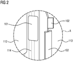
- FIG. 2 shows the monitor 101 and the outside mirror 102 from area A of FIG. 1 from the perspective of the driver in the right part of the interior of the vehicle 103.
- the monitor 101 is mounted on the A-pillar 114 of the driver's cab. Therefore, it does not cover any area of the windshield 112 or the side window 113. Through the side window 113 can be seen the two-part exterior mirror 102 on the right side of the vehicle 103.
- the outside mirror 102 covers part of the field of vision of the driver and is therefore covered by the driver Monitor 101 replaced. It is shown here only for clarification and comparison with the conventional solution.
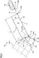
- FIG. 3 shows a three-dimensional model 107 of the trailer 106 with environment 109 in two-dimensional plan view.
- the environment 109 is shown as a flat plane E1 schematically as a rectangular pattern in the left part of the figure.
- the vehicle 103 is aligned parallel to the rectangular pattern of the plane E1, the trailer 105 in the bending angle ALPHA.
- Vehicle 103 and trailer 105 are connected to each other via a coupling point KUP.
- the outside mirrors 102 and the camera 111 already described can be seen.
- Behind the vehicle 106 a car is shown as an object 108.
- the positions of vehicle 103, trailer 105, and object 108 are indicated by object positions P3, P5, and P8.
- a trailing edge of the trailer 105 is indicated as edge K5.
- the movements of the trailer 105, the object 108 and the edge K5 are indicated by the motion vectors 1BV5, 1BV8 and 2BV5.
- a three-dimensional model 107 is calculated, that is to say the positions P5, P8 of objects 105, 108 recorded by the camera 111, including their spacing.
- positions P5, P8 in three-dimensional space are uniquely functional for positions in the two-dimensional camera image 104, the pixel space map.
- a simple and computationally efficient method of modeling is to assume the environment 109 as a flat plane E1 (bottom) and the trailer 105 as a cuboid Q1 whose side surfaces S1 are perpendicular to the plane E1 representing the ground.
- the position of the vertical rear edge K5 of the trailer is thus influenced by the parameters coupling point KUP, bending angle ALPHA of the trailer 105 relative to the vehicle 103, and width BA and length LA of the trailer 105.
- the width BA of trailers 105 typically corresponds to the maximum permitted width of 2.55 m.
- Other parameters are estimated by appropriate methods from the image of the camera 111 or other available page information. So the length LA of the trailer remains constant while driving, the bend angle ALPHA changes only slowly. According to another embodiment, these parameters are considered as additional variance in the model 107. Likewise, the simplified model assumption feeds in as variance.
- one of the parameters for example the bending angle ALPHA, initially remains unknown and is later calculated as a function of the assumed position of the rear edge K5 of the trailer.
- More elaborate methods make more sophisticated assumptions about the nature of tags 105, such as shapes other than box Q1, and surrounding 109, such as with additional objects 108.
- more advanced estimation techniques such as "structure-from-motion", or additional sensors, such as distance sensors, 3D cameras, or the like, used. Ideally, a distance estimate for all visible picture elements is created.
- a motion vector estimation is performed.
- vehicle information such as speed of the vehicle 103 and change in the kink angle ALPHA
- movements of objects 105, 108 in three-dimensional space relative to the camera 111 are determined.
- this relates to objects 108 of the environment 109, in particular the plane E1, and the trailer 105.
- the three-dimensional movement of each object 105, 108 is imaged onto a two-dimensional motion vector within the camera image 104 at the corresponding image position.
- Intrinsic parameters are, for example, the focal length, the image sensor format and the focal point.
- Extrinsic parameters are the position, main axis, and rotation of the camera on this major axis. This method can be used for any image position of interest.
- vectors P8, 1BV8 of objects 108 of environment 109 are often significantly different from vectors P5, 1BV5 of trailer 105.
- the uncertainty from model 107 of environment 109, as well as the uncertainty about vehicle information are added Variances S1BV5, S1BV8 determined for the motion vectors 1BV5, 1BV8.
- FIG. 4 shows on the left, in the middle and on the right each a monitor 101 with different image sections 104a, 104b of the camera image 104.
- the following description refers initially to the left part of FIG. 4 ,
- the image section 104a shown here shows all information relevant to the driver in this situation: the trailer 105 with its rear edge K5 and as object 108 of the environment 109 a following car.
- a bayesian estimate of the position of the rear edge K5 of the trailer is made.
- the horizontal position of the edge K5 in the camera lens-distorted camera image 104 is denoted by e
- the set of available motion vectors 2BV5 is denoted by v. It is assumed that corresponding motion vectors 2BV5 have been determined at prominent points KP1 of interest from two or more consecutive camera images 104. This is done for example by optical flow, pixel comparison or feature comparison.
- v argmax_e P v
- P model (e) is assumed to be equally distributed without loss of generality. According to other embodiments, in favor of an efficient calculation, a normal distribution is assumed, which is determined by the mean value, that is to say the most likely edge position of the edge K5, and variance, that is to say the uncertainty in the position the edge K5, is completely described. Since there is often a clear difference in color between the pendant 105 and the surroundings 109, it makes sense to include this information as P_image (e) in the calculation.
- any kind of derivation along the horizontal path of possible trailer edge positions e can be used for this purpose. For example, finite differences between successive pixel intensities or corresponding distances in the color space, wherein optionally low-pass filtered to suppress the image noise. In addition to the following mandatory standardization to the total probability 1, it is optionally normalized beforehand with imaging functions such as 1-exp (-x) or 1-1 / (x + 1) in accordance with human contrast perception.
- e) the a-posteriori probability that the motion vectors 1BV5 determined by optical flow or the like, and therefore known but not always correct, occur at an assumed position of the edge K5 of the trailer 105.
- v ⁇ v_1 ⁇
- optional normal distributions are used for simplification, which are described completely by the mean value, that is to say the predicted two-dimensional motion vector in the camera image 104, and variance, that is to say its uncertainty.
- the method for determining the motion vectors from the image information (optical flow, etc.) for each motion vector additionally provides a reliability measure w_1, w_2, w_3,...
- the occurrence probabilities are respectively weighted with the reliability measure, that is to say powered up, according to a further embodiment : P v
- e P v_ 1
- the method for determining the motion vectors 1BV5, 1BV8 from the image information is usually initialized with a presumed motion vector.
- This speeds up the calculation, and also improves the correctness of the particular motion vectors 1BV5, 1BV8.
- the motion vector prediction there is a presumption about the motion vector 1BV5, 1BV8, which, however, strongly depends on the examined value of the position e, depending on whether the position of interest belongs to the trailer 105, so-called trailer hypothesis, or if the position of interest belongs to the environment, so-called environment hypothesis.
- the determination is therefore initialized either under the assumption of the surrounding hypothesis or under hypothesis of the trailer hypothesis.
- the motion vector determination need not be carried out for each examined value of the position e. It suffices to execute them once for the environmental hypothesis and once for the trailer hypothesis.
- the edge K5 moves from that in the left part of the FIG. 4 from the image section 104a displayed on the monitor 101 into the image section 104b. This is in the middle part of the FIG. 4 shown in which the image section 104a is visible on the monitor 101, and the image section 104b is located to the right of the monitor, so is not visible to the driver.
- the image detail displayed on the monitor 101 is tracked according to the invention according to the most probable position PK of the edge K5 determined position.
- the image section 104b is then displayed on the monitor 101, in which the rear edge 5 of the trailer 105 is again visible to the driver. With the edge 5 then the underlying parts of the environment 109 are then visible to the driver.
- the image section 104a which in this situation does not contain information relevant to the driver, is indicated here to the left of the monitor 101, that is to say not visible on the latter.
- FIG. 5 shows a control unit 110 according to the invention and a flow chart of the method according to the invention.
- the control unit 110 has a modeling unit 115, a motion vector determination unit 116, an edge position determination unit 117 and an image detail tracking unit 118.
- An output of the camera 111 is connected to an input of the modeling unit 115 and an input of the motion vector detection unit 115.
- Determination unit 116 connected.
- a step S1 is executed. Its output is connected to an input of the motion vector determination unit 116 and an input of the edge position determination unit 117.
- a first step S21 and / or an alternative second step S22 are executed, and their outputs are connected to the edge position determination unit 117.
- a third step S3 is performed, its output is connected to the image detail tracking unit 118.
- a fourth step S4 is executed.
- a three-dimensional model 107 of the trailer 106 and its surroundings 109 is determined from the camera image KB of the camera 111 and model parameters MP1, MP2,....
- the model parameters are preferably those mentioned above, such as the position of the coupling point KUP, the bending angle ALPHA, etc., or other suitable parameters.
- first motion vectors 1BV5, 1BV8 are determined from the object positions P3, P5, P8 of a plurality of temporally successive camera images KB.
- the second step provides these and associated first motion vector variance values S1BV5, S1BV8.
- S 1 BVI S 1 BVI pi tj ,
- second motion vectors 2BV5 of one or more prominent points KP1 of the plurality of temporally successive camera images KB become rear edge K5 of the trailer 105 determined.
- the alternative second step provides the second motion vectors 2BV5 and associated second motion vector variance values S2BV5.
- S 2 BV 5 S 2 BV 5 K 5 tj ,
- the most probable position PK of the rear edge K5 of the trailer 105 is calculated from the position values P3, P5, P8 and the positional variance values SP3, SP5, SP8 from step S1, and / or from the motion vectors 1BVi and the position variance values S1BVi from step S21 and / or the variance values S2BVi and the second motion vectors 2BVi:
Landscapes
- Engineering & Computer Science (AREA)
- Physics & Mathematics (AREA)
- General Physics & Mathematics (AREA)
- Multimedia (AREA)
- Theoretical Computer Science (AREA)
- Remote Sensing (AREA)
- Radar, Positioning & Navigation (AREA)
- Chemical & Material Sciences (AREA)
- Combustion & Propulsion (AREA)
- Transportation (AREA)
- Mechanical Engineering (AREA)
- Signal Processing (AREA)
- Image Analysis (AREA)
Abstract
Description
- Die vorliegende Erfindung betrifft ein Verfahren zur Nachführung eines Bildausschnitts eines Kamerabildes, der auf einem Monitor zum Ersatz eines Außenspiegels eines Fahrzeugs dargestellt wird, insbesondere bei Kurvenfahrt eines aus dem Fahrzeug und einem Anhänger bestehenden Gespanns.
- Aus der
WO 2016/024405 A2 ist ein Verfahren zur Nachführung eines auf einem Monitor zum Ersatz eines Außenspiegels eines Fahrzeugs dargestellten Bildausschnitts eines Kamerabildes eines aus dem Fahrzeug und einem Anhänger bestehenden Gespanns bei Kurvenfahrt bekannt. Dort wird ein Monitorsystem als Ersatz für einen Rückspiegel gezeigt, bei dem der dargestellte Bildausschnitt der Bewegung der Kopfposition des Fahrers angepasst wird. Der Fahrer bewegt den Kopf, wenn der Anhänger bei Kurvenfahrt auf einem konventionellen Rückspiegel nach "außen" wandert, um das Ende des Anhängers weiterhin im Blick zu haben. Die Bewegung der Kopfposition des Fahrers wird dazu detektiert. Dazu ist eine zuverlässige Bewegungsdetektion erforderlich, was im Allgemeinen nur aufwendig realisierbar ist. Kopfbewegungen des Fahrers, die aus anderen Gründen als zur Änderung des für den Fahrer im herkömmlichen Rückspiegel sichtbaren Bildausschnitts erfolgen, führen zu unerwünschten Anpassungen des Bildausschnitts auf dem Monitor. - Es wird ein demgegenüber verbessertes Verfahren zur Nachführung des Bildausschnitts vorgeschlagen.
- Erfindungsgemäß wird zunächst ein dreidimensionales Modell mit der Objektposition zumindest eines Objekts aus dem Kamerabild und vorgegebenen Modellierungsparametern bestimmt. Neben dem Anhänger werden sinnvollerweise auch Objekte der Umgebung, wie andere Fahrzeuge, Gebäude, Personen oder andere, sich in der Nähe des Fahrzeugs befindende Gegenstände im Modell bestimmt. Wie ein derartiges Modell bestimmt wird ist beispielsweise aus K. Häming, G. Peters (2010) "The structure-from-motion reconstruction pipeline - a survey with focus on short image sequences", Kybernetika, bekannt. Weiterhin wird aus dem Kamerabild ein Bewegungsvektor zu zumindest einem markanten Punkt auf dem Anhänger bestimmt. Idealerweise handelt es sich bei einem der Punkte um eine Hinterkante des Anhängers, die sich bei Kurvenfahrt innerhalb des Kamerabildes bewegt, und auch dann für den Fahrer im Monitor sichtbar sein soll. Ein von Null abweichender Bewegungsvektor der Hinterkante deutet auf Kurvenein- oder -ausfahrt hin, was ein Nachführen des auf dem Monitor dargestellten Bildausschnitts erforderlich macht. Aus der Objektposition und Informationen, die aus der Bestimmung der Bewegungsvektoren gewonnen werden, wird dann die wahrscheinlichste Position der Kante bestimmt. Stimmt die Verschiebung von aus dem Modell gewonnenen Objektpositionen für aufeinanderfolgende Kamerabilder mit dem Bewegungsvektor überein, so ist die Wahrscheinlichkeit hoch, dass es sich um die korrekt bestimmte Position der Kante handelt. Stimmen diese nicht überein, so ist dies weniger wahrscheinlich. Der Bildausschnitt wird dann entsprechend der wahrscheinlichsten Position der Kante nachgeführt. Die auf diese Weise bestimmte wahrscheinlichste Position der Hinterkante ermöglicht eine zuverlässigere Nachführung des Bildausschnitts bei relativ niedrigem Berechnungsaufwand. Solange man nicht weiß, wo die Hinterkante ist, kann man auch nicht genau dort einen Vektor bestimmen. Stattdessen werden mehrere Vektoren an markanten Bildpositionen, wie zum Beispiel Eck-oder Kantenpunkte der Anhängerplanenbeschriftung, bestimmt. Dabei wird angenommen, dass wahrscheinlich einer davon tatsächlich auf der Hinterkante liegt. Dies ist jedoch zur Funktion des erfindungsgemäßen Verfahrens nicht notwendig. Für die Funktionalität des Verfahrens ist es auch günstig, wenn zumindest ein Vektor zudem auf die Umgebung, den Boden, fällt.
- Vorteilhafterweise werden folgende Annahmen und Parameter für die Modellierung verwendet: Die Umgebung wird im ersten Ansatz als flache Ebene angenommen. Der Anhänger wird als Quader mit senkrecht zur flachen Ebene stehenden Seitenflächen angenommen. Als Parameter werden der Kupplungspunkt von Fahrzeug und Anhänger sowie die Breite und die Länge des Anhängers genommen. Mit dieser geringen Anzahl von Annahmen und Parametern wird eine für den zu erreichenden Zweck hinreichend gute Modellierung erreicht, die keine allzu hohen Anforderungen an die Rechenleistung stellt. Da man im schlechtesten Fall keinerlei Informationen darüber besitzt, welche Art von Anhänger angehängt ist, wird hier davon ausgegangen, dass es lediglich einen Knickpunkt gibt, dass es nur eine Hinterachse gibt, dass diese sich in einem bekannten und gleichbleibenden Abstand von der Anhängerhinterkante befindet, dass die Hinterkante nicht mitlenkt und so weiter. Alle diese Unsicherheiten fließen über die Varianz in das Modell ein. Bekannte Approximationen im Modell werden gegebenenfalls über erhöhte Varianz berücksichtigt.
- Erfindungsgemäß wird der Kupplungspunkt von Fahrzeug und Anhänger als fester Parameter angenommen, dessen Position aus der Fahrzeuggeometrie und der festen Position der Kamera bekannt ist. Für die Breite und die Länge des Anhängers werden im ersten Ansatz die maximal üblichen Werte angenommen, da das Fahrzeug mit unterschiedlichen Anhängern betrieben werden kann. Auch ein und derselbe Anhänger kann unterschiedliche Konfigurationen aufweisen. Diese Schätzwerte werden im Vergleich mit den folgenden Kamerabildern an die Realität angepasst. Diese Parameterwahl hat den Vorteil, eine gute Startkonfiguration zu liefern, die leicht an die tatsächliche Konfiguration anpassbar ist.
- Gemäß der Erfindung werden Positionsvarianzwerte zu Objektpositionen des dreidimensionalen Modells bestimmt sowie Bewegungsvektorvarianzwerte zu den Bewegungsvektoren. Die wahrscheinlichste Position der Kante wird dann bestimmt als Wert, an dem die A-Posteriori-Wahrscheinlichkeit einen Maximalwert erreicht. Die Varianzwerte lassen sich aus den Verfahren zur Bestimmung von Position und Bewegungsvektor leicht bestimmen. Ihr Produkt liefert eine gute Aussage über die wahrscheinlichste Kantenposition.
- Vorteilhafterweise werden Bewegungsvektor und Bewegungsvarianzwert aus dem dreidimensionalen Modell für zumindest ein Objekt bestimmt. Das Objekt ist der Anhänger, für weitere Objekte ist diese Bestimmung ebenfalls sinnvoll. Ebenfalls vorteilhaft ist es, Bewegungsvektor und Bewegungsvarianzwert zu zumindest einem markanten Punkt der hinteren Kante des Anhängers zu bestimmen. Auch eine kombinierte Verwendung der Varianzwerte aus Modell und aus Kantendetektion als Produkt hat sich als sinnvoll herausgestellt.
- Eine erfindungsgemäße Steuerungseinheit weist eine Modellbildungseinheit, eine Bewegungsvektor-Bestimmungs-Einheit, eine Kantenpositions-Bestimmungs-Einheit und eine Bildausschnitt-Nachführungs-Einheit auf. Funktion und Vorteile entsprechen denjenigen, die zum Verfahren beschrieben sind.
- In anderen Worten betrifft die Erfindung ein Kamera-MonitorSystem zum Ersatz des Außenspiegels in LKWs, um Treibstoffkosten einzusparen. Eine Nachführung des auf dem Display angezeigten Bildausschnittes nach außen ist bei angehängtem Anhänger in Kurvenfahrten notwendig, um dem Fahrer die Sicht auf die Hinterkante seines Anhängers anstatt nur auf dessen Seitenplane zu ermöglichen. Insbesondere beim Rangieren ergibt sich diese Notwendigkeit auch durch die wegfallende Möglichkeit, durch Bewegung des Kopfes das Sichtfeld zu verändern, wie dies bei herkömmlichen Spiegeln der Fall ist.
- Für die Nachführung wird eine automatische Erkennung der aktuellen x-/y-Position der vertikalen Hinterkante des Anhängers im Bild vorgeschlagen. Da sich die Hinterkante über eine gewisse Länge erstreckt, gelten für die y-Position gewisse Vorgaben, zum Beispiel soll sie einen Meter über dem Boden erkannt werden. Zu beachten ist hierbei, dass eine Vielzahl verschiedener Anhänger verwendet werden können, und dass die Rechenleistung des Bildverarbeitungssystems sehr stark eingeschränkt ist.
- Auf Einzelbildern basierende Kantendetektionsverfahren, wie die sogenannte "Canny edge detection", sind für die gegebene Aufgabe größtenteils ungeeignet, da oftmals viele weitere Kanten im Bild enthalten sind. Diese Kanten sind unter anderem Struktur und Bedruckung der LKW Anhängerplane, Fahrspurmarkierungen auf der Straße, sichtbare Fremdfahrzeuge, weitere Objekte der Umgebung wie z. B. Beschilderung und Bauwerke. Kanten dieser Objekte sind nicht in jeder Situation und mit überschaubarem Rechenaufwand von der Anhängerhinterkante zu unterscheiden.
- Umgebungsrekonstruktions- und Objekterkennungsverfahren wie zum Beispiel das sogenannte "Structure-from-motion" Verfahren bedienen sich daher der leicht verschobenen Position von markanten Objektpunkten in mehreren, aus unterschiedlichen Positionen aufgenommenen Bildern, die beispielsweise von unterschiedlichen Kameras stammen oder bei bewegter Kamera zu aufeinanderfolgenden Zeitpunkten aufgezeichnet wurden. Hierbei wird insbesondere die unterschiedliche Verschiebung von Vordergrund- und Hintergrundobjekten genutzt. Diese treten aufgrund von unterschiedlichen Abständen zur Kamera oder aufgrund von unabhängiger Objektbewegung auf.
- Sowohl eine Bewegung der Kamera zusammen mit dem LKW, als auch eine Bewegung des Anhängers unabhängig von seiner Umgebung ist bei typischen Fahrsituationen gegeben. Kritisch ist jedoch nach wie vor eine robuste Erkennung, Lokalisierung und Unterscheidung der Anhängerkante von anderen Objektkanten im Bild.
- Gemäß der Erfindung wird in einem ersten Schritt ein dreidimensionales Modell der Umgebung bestimmt, in einem zweiten Schritt eine Bewegungsvektorvorhersage durchgeführt und in einem dritten Schritt eine Schätzung der Position der Hinterkante des Anhängers vorgenommen.
- Die Erfindung ist geeignet, die Hinterkante von Anhängern bei Nutzfahrzeugen oder PKWs zu erkennen. Dabei kann die Kamera sowohl eine nach hinten gerichtete Kamera zum Erzeugen eines Rückspiegel-Ersatz-Bildes sein als auch eine andere geeignete Kamera, wie beispielsweise eine Rückfahrkamera.
- Vorteile der Erfindung sind unter anderem: Es werden Bewegungsunstetigkeit als auch Intensitätsunstetigkeit im Bild berücksichtigt. Das erfindungsgemäße Verfahren ist robust gegenüber Unstetigkeiten in der Bildintensität, wie beispielsweise Struktur und Bedruckung der LKW Anhängerplane, Fahrspurmarkierungen auf der Straße, sichtbare Fremdfahrzeuge, weitere Objekte der Umgebung wie Beschilderung, Bauwerke oder ähnliches. Das Verfahren ist ebenfalls robust gegenüber nicht-relevanter Bewegung, wie beispielsweise vorbeifahrenden Fahrzeugen, Bewegungsvektorunstetigkeiten von statischen Objekten wie Verkehrszeichen oder ähnlichem, sich bewegenden Spiegelungen auf der Anhängerplane, oder bewegte Schatten. Das erfindungsgemäße Verfahren ist auch robust gegenüber schlechter Bewegungsvektorschätzung. Durch Hinzunahme der geschätzten Kantenposition aus vorherigen Bildern springt die erkannte Kante typischerweise nicht von Bild zu Bild. Weiterhin werden Unsicherheiten im Modell direkt gegeneinander abgewogen und führen unter der zur Verfügung stehenden Information zu der wahrscheinlichsten Kantenposition. Gemäß einer Variante des Verfahrens wird die Verlässlichkeit der Bewegungsvektoren berücksichtigt. Durch die adaptive Initialisierung der Bewegungsvektorbestimmung werden bereits in diesem Schritt Fehlschätzungen unwahrscheinlicher. Das erfindungsgemäße Verfahren erfordert nur einen geringen Rechenaufwand, und ist daher geeignet für die Verwendung in eingebetteten Systemen.
- Weitere Vorteile und Varianten der Erfindung sind auch der folgenden Beschreibung von Ausführungsbeispielen anhand der Figuren zu entnehmen. Dabei zeigen:
- Fig. 1
- Gespann, in dem ein erfindungsgemäßes Verfahren implementiert ist;
- Fig. 2
- Monitor und Außenspiegel aus
Fig. 1 aus Sicht des Fahrers; - Fig. 3
- Modell eines Gespanns mit Umgebung in Draufsicht;
- Fig. 4
- Monitor mit unterschiedlichen Bildausschnitten;
- Fig. 5
- erfindungsgemäße Steuerungseinheit und Flussdiagramm des erfindungsgemäßen Verfahrens.
-
Figur 1 zeigt ein Gespann 106 bestehend aus Fahrzeug 103 und Anhänger 105. Die Umgebung 109 des Gespanns 106 ist hier schematisch als Ebene E1 dargestellt. Das Fahrzeug 103 ist mit einer Steuerungseinheit 110 zur Verarbeitung eines Kamerabildes einer Kamera 111 ausgestattet. Die Steuerungseinheit 110 berechnet gemäß dem erfindungsgemäßen Verfahren einen Bildausschnitt, der auf einem im Innenraum des Fahrzeugs 103 angebrachten Monitor 101 dargestellt wird. Dieser Bildausschnitt entspricht dem, was der Fahrer des Fahrzeugs 103 üblicherweise in seiner normalen Sitzposition auf den Außenspiegeln 102 sieht beziehungsweise was er durch Drehen oder Verschieben des Kopfes dort sehen kann. Der eingekreiste Bereich A zeigt den Übergangsbereich zwischen Windschutzscheibe 112 und rechtem Seitenfenster 113 (hier nicht sichtbar). Der Bereich A wird in der folgenden Abbildung aus Sicht des Fahrers gezeigt. -
Figur 2 zeigt den Monitor 101 und den Außenspiegel 102 aus Bereich A derFigur 1 aus Sicht des Fahrers im rechten Teil des Innenraums des Fahrzeugs 103. Der Monitor 101 ist an der A-Säule 114 der Fahrerkabine angebracht. Er verdeckt daher keinen Bereich der Windschutzscheibe 112 oder der Seitenfenster 113. Durch das Seitenfenster 113 sieht man den hier aus zwei Teilen bestehenden Außenspiegel 102 auf der rechten Seite des Fahrzeugs 103. Der Außenspiegel 102 verdeckt einen Teil des Sichtfeldes des Fahrers und wird daher durch den Monitor 101 ersetzt. Er ist hier nur zur Verdeutlichung und zum Vergleich mit der herkömmlichen Lösung dargestellt. -
Figur 3 zeigt ein dreidimensionales Modell 107 des Gespanns 106 mit Umgebung 109 in zweidimensionaler Draufsicht. Die Umgebung 109 ist als flache Ebene E1 schematisch als Rechteckmuster im linken Teil der Abbildung dargestellt. Das Fahrzeug 103 ist parallel zum Rechteckmuster der Ebene E1, der Anhänger 105 im Knickwinkel ALPHA dazu ausgerichtet. Fahrzeug 103 und Anhänger 105 sind über einen Kupplungspunkt KUP miteinander verbunden. Am Fahrzeug 103 erkennt man die bereits beschriebenen Außenspiegel 102 und die Kamera 111. Hinter dem Gespann 106 ist ein PKW als Objekt 108 dargestellt. Die Positionen von Fahrzeug 103, Anhänger 105 und Objekt 108 sind durch die Objektpositionen P3, P5 und P8 angegeben. Eine Hinterkante des Anhängers 105 ist als Kante K5 angegeben. Die Bewegungen des Anhängers 105, des Objekts 108 und der Kante K5 sind durch die Bewegungsvektoren 1BV5, 1BV8 und 2BV5 angegeben. - In einem ersten Schritt des erfindungsgemäßen Verfahrens wird ein dreidimensionales Modell 107 berechnet, das heißt die Positionen P5, P8 von von der Kamera 111 aufgenommenen Objekten 105, 108 inklusive deren Abstand. Mit Hilfe von intrinsischer und extrinsischer Offlinekalibrierung der Kamera 111 relativ zum Fahrzeug 103 sowie zum Boden ist es ermöglicht, Positionen P5, P8 im dreidimensionalen Raum eindeutig auf Positionen im zweidimensionalen Kamerabild 104, dem Pixelraum, funktional abzubilden. Eine einfache und recheneffiziente Methode zur Modellierung besteht darin, die Umgebung 109 als flache Ebene E1 (Boden) und den Anhänger 105 als Quader Q1 anzunehmen, dessen Seitenflächen S1 senkrecht zur den Boden darstellenden Ebene E1 stehen. Die Position der vertikalen hinteren Kante K5des Anhängers wird damit von den Parametern Kupplungspunkt KUP, Knickwinkel ALPHA des Anhängers 105 relativ zum Fahrzeug 103, sowie Breite BA und Länge LA des Anhängers 105 beeinflusst.
- Abhängig von der Realisierung des Systems werden gemäß einer ersten Ausführungsform für einige dieser Parameter fixe Annahmen gemacht. Der Kupplungspunkt KUP ist bei fest verschraubter Kamera 111 bekannt, die Breite BA von Anhängern 105 entspricht typischerweise der erlaubten Maximalbreite von 2,55 m. Weitere Parameter werden mit geeigneten Verfahren aus dem Bild der Kamera 111 oder anderen zur Verfügung stehenden Seiteninformationen geschätzt. So bleibt die Länge LA des Anhängers während der Fahrt konstant, der Knickwinkel ALPHA ändert sich nur langsam. Gemäß einer anderen Ausführungsform werden diese Parameter als zusätzliche Varianz im Modell 107 berücksichtigt. Ebenso fließt die vereinfachte Modellannahme als Varianz ein.
- Optional bleibt gemäß einer weiteren Ausführungsform einer der Parameter, zum Beispiel der Knickwinkel ALPHA, zunächst unbekannt und wird später in Abhängigkeit von der angenommenen Position der hinteren Kante K5 des Anhängers berechnet. Aufwendigere Verfahren machen gemäß weiterer Ausführungsformen anspruchsvollere Annahmen über die Beschaffenheit von Anhänger 105, beispielsweise andere Formen als Quader Q1, und Umgebung 109, beispielsweise mit zusätzlichen Objekten 108. Gemäß weiterer Ausführungsformen werden fortgeschrittenere Schätzverfahren, wie beispielsweise "structure-from-motion", oder zusätzliche Sensorik, wie Abstandssensoren, 3D-Kameras, oder ähnliches, eingesetzt. Im Idealfall entsteht hierbei eine Abstandsschätzung für alle sichtbaren Bildelemente.
- In einem zweiten Schritt des erfindungsgemäßen Verfahrens wird eine Bewegungsvektorschätzung vorgenommen. Bei bekannten oder geschätzten Fahrzeuginformationen wie zum Beispiel Geschwindigkeit des Fahrzeugs 103 und Änderung des Knickwinkels ALPHA werden Bewegungen von Objekten 105, 108 im dreidimensionalen Raum relativ zur Kamera 111 bestimmt. Insbesondere betrifft dies Objekte 108 der Umgebung 109, insbesondere die Ebene E1, und den Anhänger 105. Mit Hilfe von Parametern der Kamera 111 wird die dreidimensionale Bewegung jedes Objekts 105, 108 auf einen zweidimensionalen Bewegungsvektor innerhalb des Kamerabildes 104 an der entsprechenden Bildposition abgebildet. Intrinsische Parameter sind dabei beispielsweise die Brennweite, das Bildsensorformat und der Brennpunkt. Extrinsische Parameter sind die Position, Hauptachse und Drehung der Kamera auf dieser Hauptachse. Dieses Verfahren lässt sich für jede beliebige Bildposition von Interesse anwenden. Oftmals unterscheiden sich dadurch Vektoren P8, 1BV8 von Objekten 108 der Umgebung 109 deutlich von Vektoren P5, 1BV5 des Anhängers 105. Ebenso wie im ersten Schritt werden auch hier durch Hinzunahme der Unsicherheit aus dem Modell 107 der Umgebung 109, sowie der Unsicherheit über die Fahrzeuginformation Varianzen S1BV5, S1BV8 für die Bewegungsvektoren 1BV5, 1BV8 bestimmt.
-
Figur 4 zeigt links, in der Mitte und rechts jeweils einen Monitor 101 mit unterschiedlichen Bildausschnitten 104a, 104b des Kamerabilds 104. Die folgende Beschreibung bezieht sich zunächst auf den linken Teil derFigur 4 . Der hier dargestellte Bildausschnitt 104a zeigt alle für den Fahrer in dieser Situation relevanten Informationen: Den Anhänger 105 mit seiner hinteren Kante K5 sowie als Objekt 108 der Umgebung 109 einen nachfolgenden PKW. - In einem dritten Schritt des erfindungsgemäßen Verfahrens wird eine Bayes-Schätzung der Position der hinteren Kante K5 des Anhängers vorgenommen. Die horizontale Position der Kante K5 im kameralinsenentzerrten Kamerabild 104 wird mit e, die Menge der zur Verfügung stehenden Bewegungsvektoren 2BV5 wird mit v bezeichnet. Es wird vorausgesetzt, dass entsprechende Bewegungsvektoren 2BV5 an markanten Punkten KP1 von Interesse aus zwei oder mehr aufeinanderfolgenden Kamerabildern 104 bestimmt wurden. Dies erfolgt beispielsweise durch optischen Fluss, Pixelvergleich oder Merkmalsvergleich.
- Unter Zuhilfenahme des Satzes von Bayes wird nun die wahrscheinlichste Hinterkantenposition e, in der Abbildung als wahrscheinlichste Position PK bezeichnet, im Kamerabild 104 wie folgt bestimmt:

- Hierbei bezeichnet P(e) die A-Priori-Wahrscheinlichkeit dafür, dass sich die Anhängerhinterkante K5 im aktuellen Kamerabild 104 an der Position e befindet. Sie berechnet sich aus

- Falls weder vorherige Positionen der Kante K5 des Anhängers bestimmt wurden, noch das Modell 107 der Umgebung 109 einen Anhaltspunkt liefert, zum Beispiel wenn ein Parameter wie der Knickwinkel ALPHA unbekannt ist, wird P model(e) ohne Beschränkung der Allgemeinheit gleichverteilt angenommen. Gemäß anderer Ausführungsformen wird zugunsten einer effizienten Berechnung eine Normalverteilung angenommen, die durch Mittelwert, das heißt der wahrscheinlichsten Kantenposition der Kante K5, und Varianz, das heißt der Unsicherheit in der Position der Kante K5, vollständig beschrieben wird. Da zwischen Anhänger 105 und Umgebung 109 oftmals ein deutlicher Farbunterschied besteht, bietet es sich an, diese Information als P_image(e) in die Berechnung einfließen zu lassen. Jegliche Art von Ableitung entlang des horizontalen Pfades möglicher Anhängerkantenpositionen e kann hierzu zur Anwendung kommen. Beispielsweise finite Differenzen zwischen aufeinanderfolgenden Pixelintensitäten oder entsprechende Abstände im Farbraum, wobei zur Unterdrückung des Bildrauschens optional zuvor tiefpassgefiltert wird. Neben der nachfolgenden obligatorischen Normierung auf die Gesamtwahrscheinlichkeit 1 wird optional zuvor mit Abbildungsfunktionen wie 1-exp(-x) oder 1-1/(x+1) entsprechend der menschlichen Kontrastwahrnehmung normiert.
- Es bezeichnet weiterhin P(v|e) die A-Posteriori-Wahrscheinlichkeit dafür, dass die durch optischen Fluss o. ä. bestimmten - und daher bekannten aber nicht immer richtigen - Bewegungsvektoren 1BV5 bei einer angenommenen Position der Kante K5 des Anhängers 105 auftreten. Bei nur einem Bewegungsvektor v = {v_1} folgen sie direkt aus der Wahrscheinlichkeitsverteilung, die aus der Vorhersage des Bewegungsvektors 1BV5, der hier v_1 entspricht, hervorgeht. Auch hier kommen optional zur Vereinfachung Normalverteilungen zur Anwendung, die durch Mittelwert, das heißt dem vorhergesagten zweidimensionalen Bewegungsvektor im Kamerabild 104, und Varianz, das heißt dessen Unsicherheit, vollständig beschrieben werden.
- Falls, wie im Regelfall, mehrere Vektoren v = {v_1, v_2, v_3, ...} für mehrere markante Punkte KP1 von Interesse existieren, berechnet sich P(v|e) aus

- Falls das Verfahren zur Bestimmung der Bewegungsvektoren aus der Bildinformation (optischer Fluss, etc.) für jeden Bewegungsvektor zusätzlich ein Verlässlichkeitsmaß w_1, w_2, w_3,... liefert, werden die Auftretenswahrscheinlichkeiten gemäß einer weiteren Ausführungsform jeweils mit dem Verlässlichkeitsmaß gewichtet, das heißt potenziert:

- Dies geht nach Logarithmierung in herkömmliche Multiplikation über.
- Optional wird das Verfahren zur Bestimmung der Bewegungsvektoren 1BV5, 1BV8 aus der Bildinformation (optischer Fluss, etc.) im Regelfall mit einem vermuteten Bewegungsvektor initialisiert. Dies beschleunigt die Berechnung, und verbessert auch die Korrektheit der bestimmten Bewegungsvektoren 1BV5, 1BV8. Durch die Bewegungsvektorvorhersage besteht eine Vermutung über den Bewegungsvektor 1BV5, 1BV8, die jedoch stark vom untersuchten Wert der Position e abhängt, je nachdem ob die Position von Interesse zum Anhänger 105 gehört, sogenannte Anhängerhypothese, oder ob die Position von Interesse zur Umgebung gehört, sogenannte Umgebungshypothese. Abhängig vom im Maximierungprozess gegebenen e wird die Bestimmung daher entweder unter der Vermutung der Umgebungshypothese oder unter Vermutung der Anhängerhypothese initialisiert. Die Bewegungsvektorbestimmung braucht hierzu nicht für jeden untersuchten Wert der Position e ausgeführt werden. Es genügt, sie einmal für die Umgebungshypothese und einmal für die Anhängerhypothese auszuführen.
- Eine einfachere Alternative zur Bayes-Schätzung besteht darin, dass anstelle der beschriebenen Bayes'schen Entscheidung ein beliebiges einfacheres Verfahren verwendet wird, um die Unstetigkeitsposition zu erkennen, an der die Bewegungsvektoren 1BV5, 1BV8 sich stark zwischen Anhänger 105 und Umgebung 109 unterscheiden. Zugunsten der Robustheit bezüglich Bewegungsvektorstörungen werden in diesem Fall Bewegungsvektoren, die sich stark von der Bewegungsvektorprädiktion unterscheiden, sogenannte Ausreißer, aussortiert.
- Bei Kurveneinfahrt des Gespanns 106 wandert die Kante K5 von der im linken Teil der
Figur 4 dargestellten Position ausgehend aus dem auf dem Monitor 101 dargestellten Bildausschnitt 104a heraus in den Bildausschnitt 104b. Dies ist im mittleren Teil derFigur 4 gezeigt, in dem der Bildausschnitt 104a auf dem Monitor 101 sichtbar ist, und der Bildausschnitt 104b rechts neben dem Monitor liegt, also für den Fahrer nicht sichtbar ist. - Der auf dem Monitor 101 dargestellte Bildausschnitt wird erfindungsgemäß entsprechend der als wahrscheinlichster Position PK der Kante K5 bestimmten Position nachgeführt. Wie im rechten Teil der
Figur 4 gezeigt, wird dann der Bildausschnitt 104b auf dem Monitor 101 dargestellt, in dem die hintere Kante 5 des Anhängers 105 wieder für den Fahrer sichtbar ist. Mit der Kante 5 sind dann auch wieder die dahinterliegenden Teile der Umgebung 109 für den Fahrer sichtbar. Der Bildausschnitt 104a, der in dieser Situation keine für den Fahrer relevante Information enthält, ist hier links neben dem Monitor 101, also auf diesem nicht sichtbar, angedeutet. -
Figur 5 zeigt eine erfindungsgemäße Steuerungseinheit 110 und ein Flussdiagramm des erfindungsgemäßen Verfahrens. Die Steuerungseinheit 110 hat eine Modellbildungseinheit 115, eine Bewegungsvektor-Bestimmungs-Einheit 116, eine Kantenposition-Bestimmungs-Einheit 117 und eine Bildausschnitt-Nachführungs-Einheit 118. Ein Ausgang der Kamera 111 ist mit einem Eingang der Modellbildungseinheit 115 und einem Eingang der Bewegungsvektor-Bestimmungs-Einheit 116 verbunden. In der Modellbildungseinheit 115 wird ein Schritt S1 ausgeführt. Ihr Ausgang ist mit einem Eingang der Bewegungsvektor-Bestimmungs-Einheit 116 und einem Eingang der Kantenposition-Bestimmungs-Einheit 117 verbunden. In der Bewegungsvektor-Bestimmungs-Einheit 116 werden ein erster Schritt S21 und/oder ein alternativer zweiter Schritt S22 ausgeführt, ihre Ausgänge sind mit der Kantenposition-Bestimmungs-Einheit 117 verbunden. In dieser wird ein dritter Schritt S3 ausgeführt, ihr Ausgang ist mit der Bildausschnitt-Nachführungs-Einheit 118 verbunden. In dieser wird ein vierter Schritt S4 ausgeführt. - Im ersten Schritt S1 wird aus dem Kamerabild KB der Kamera 111 und Modellparametern MP1, MP2, ... ein dreidimensionales Modell 107 des Gespanns 106 und seiner Umgebung 109 bestimmt. Die Modellparameter sind dabei vorzugsweise die oben genannten, wie die Position des Kupplungspunkts KUP, der Knickwinkel ALPHA etc., oder andere geeignete Parameter. Der erste Schritt S1 liefert Objektpositionen P3, P5, P8 von Fahrzeug 103, Anhänger 105 sowie von weiteren Objekten 108 und dazugehörige Positionsvarianzwerte SP3, SP5, SP8, mit

- Im zweiten Schritt S21 werden aus den Objektpositionen P3, P5, P8 mehrerer zeitlich aufeinanderfolgender Kamerabilder KB erste Bewegungsvektoren 1BV5, 1BV8 bestimmt. Der zweite Schritt liefert diese sowie dazugehörige erste Bewegungsvektorvarianzwerte S1BV5, S1BV8. Die Bewegungsvektoren 1BVi hängen von den Objektpositionen Pi(tj) zu unterschiedlichen Zeitpunkten tj ab, das heißt von zeitlich aufeinanderfolgenden Kamerabildern KB(tj):

- Im alternativen zweiten Schritt S22 werden aus mehreren zeitlich aufeinanderfolgenden Kamerabildern KB zweite Bewegungsvektoren 2BV5 eines oder mehrerer markanter Punkte KP1 der hinteren Kante K5 des Anhängers 105 bestimmt. Der alternative zweite Schritt liefert die zweiten Bewegungsvektoren 2BV5 sowie dazugehörige zweite Bewegungsvektorvarianzwerte S2BV5. Die zweiten Bewegungsvektoren 2BV5 und ihre Varianzwerte S2BV5 hängen von den Positionen der Kante K5(tj) zu unterschiedlichen Zeitpunkten tj ab:

- Im dritten Schritt S3 wird die wahrscheinlichste Position PK der hinteren Kante K5 des Anhängers 105 aus den Positionswerten P3, P5, P8 und den Positionsvarianzwerten SP3, SP5, SP8 aus Schritt S1, und/oder aus den Bewegungsvektoren 1BVi und den Positionsvarianzwerten S1BVi aus Schritt S21 und/oder den Varianzwerten S2BVi und den zweiten Bewegungsvektoren 2BVi bestimmt:


- Gegebenenfalls werden die Bewegungsvektoren noch mit einem Anpassungsfaktor multipliziert. Dabei wird eine Verteilungsfunktion Di verwendet, zum Beispiel die Gauß'sche Normalverteilung:

- Hier wird der Wert für die wahrscheinlichste Position PK entweder aus einer der oben genannten Formeln bestimmt, oder aus mehreren dieser Formeln wird ein Mittelwert bestimmt, oder PK wird als derjenige Wert bestimmt, bei dem die aus Positionswerten und aus Bewegungsvektoren gebildete Summe maximal wird:

- Es liegt im Ermessen des Fachmanns, je nach gegebenen Randbedingungen, auch andere Kombinationen oder Vereinfachungen zu wählen.
- Im vierten Schritt S4 wird der Bildausschnitt KBA des Kamerabildes KB entsprechend der wahrscheinlichste Position PK der hinteren Kante K5 des Anhängers 105 angepasst:

Claims (7)
- Verfahren zur Nachführung eines auf einem Monitor (101) zum Ersatz eines Außenspiegels (102) eines Fahrzeugs (103) dargestellten Bildausschnitts (104a, 104b) eines Kamerabildes (104) bei Kurvenfahrt eines aus dem Fahrzeug (103) und einem Anhänger (105) bestehenden Gespanns (106), wobei- ein dreidimensionales Modell (107) mit der Objektposition (P3, P5, P8) zumindest eines Objekts (103, 105, 108) aus dem Kamerabild (104, KB) und vorgegebenen Modellparametern (MP1, MP2, ...) bestimmt wird,- aus dem Kamerabild (104) ein Bewegungsvektor (1BV5, 2BV5) zu zumindest einem markanten Punkt (KP1) auf dem Anhänger (105) bestimmt wird,- die wahrscheinlichste Position (PK) des Punkts (KP1) aus der Objektposition (P5) und der Bestimmung des Bewegungsvektors (1BV5, 2BV5) bestimmt wird, und- der Bildausschnitt (104a, 104b) entsprechend der wahrscheinlichsten Position (PK) des Punkts (KP1) nachgeführt wird.
- Verfahren nach Anspruch 1, wobei als Modellparameter (MP1, MP2, ...) für das dreidimensionale Modell (107) zumindest eines der folgenden verwendet wird:- die Umgebung (109) als flache Ebene (E1),- der Anhänger (105) als Quader (Q1) mit senkrecht zur flachen Ebene (E1) stehenden Seitenflächen (S1),- der Kupplungspunkt (KUP) von Fahrzeug (103) und Anhänger (105),- Breite (BA) und/oder Länge (LA) des Anhängers (105).
- Verfahren nach Anspruch 2, wobei für einige der Modellparameter (KUP, BA) fixe Annahmen, und für andere Modellparameter (BA, LA) Schätzungen verwendet werden.
- Verfahren nach einem der vorhergehenden Ansprüche, wobei- Positionsvarianzwerte (SP5, SP8) zu Objektpositionen (P5, P8) des dreidimensionalen Modells (107), und- Bewegungsvektorvarianzwerte (S1BV5, S2BV5) zu den Bewegungsvektoren (1BV5, 2BV5) bestimmt werden, und daraus- die wahrscheinlichste Position (PK) des Punkts (KP1) bestimmt wird als Position, bei der die A-Posteriori-Wahrscheinlichkeit einen Maximalwert erreicht.
- Verfahren nach einem der vorhergehenden Ansprüche, wobei als Bewegungsvektor und Bewegungsvarianzwert aus dem Modell (107) mindestens ein erster Bewegungsvektor (1BV5, 1BV8) und mindestens ein erster Bewegungsvektorvarianzwert (S1BV5, S1BV8) für zumindest ein Objekt (105, 108) des Modells (107) bestimmt wird.
- Verfahren nach einem der vorhergehenden Ansprüche, wobei als Bewegungsvektor und Bewegungsvarianzwert mindestens ein zweiter Bewegungsvektor (2BV5) und mindestens ein zweiter Bewegungsvektorvarianzwert (S2BV5) zu zumindest einem markanten Punkt (KP1) auf dem Anhänger (105) bestimmt wird.
- Steuerungseinheit (110) zur Nachführung eines auf einem Monitor (101) zum Ersatz eines Außenspiegels (102) eines Fahrzeugs (103) dargestellten Bildausschnitts (104a, 104b) eines Kamerabildes (104) bei Kurvenfahrt eines aus dem Fahrzeug (103) und einem Anhänger (105) bestehenden Gespanns (106), aufweisend:- eine Modellbildungseinheit (115) mittels der ein dreidimensionales Modell (107) mit der Objektposition (P3, P5, P8) zumindest eines Objekts (103, 105, 108) aus dem Kamerabild (104, KB) und vorgegebenen Modellierungsparametern (MP1, MP2, ...) bestimmt wird,- eine Bewegungsvektor-Bestimmungs-Einheit (116) mittels der aus dem Kamerabild (104) ein Bewegungsvektor (1BV5, 2BV5) zu zumindest einem markanten Punkt (KP1) auf dem Anhänger (105) bestimmt wird,- eine Kantenpositions-Bestimmungs-Einheit (117) mittels der die wahrscheinlichste Position (PK) des Punkts (KP1) aus der Objektposition (P5) und der Bestimmung des Bewegungsvektors (1BV5, 2BV5) bestimmt wird, und- eine Bildausschnitt-Nachführungs-Einheit (118) mittels der der Bildausschnitt (KBA, 104a, 104b) entsprechend der wahrscheinlichsten Position (PK) des Punkts (KP1) nachgeführt wird.
Applications Claiming Priority (1)
| Application Number | Priority Date | Filing Date | Title |
|---|---|---|---|
| DE102016216962.9A DE102016216962B3 (de) | 2016-09-07 | 2016-09-07 | Verfahren und Steuerungseinheit zur Nachführung eines Bildausschnitts |
Publications (2)
| Publication Number | Publication Date |
|---|---|
| EP3293971A1 true EP3293971A1 (de) | 2018-03-14 |
| EP3293971B1 EP3293971B1 (de) | 2022-06-01 |
Family
ID=59655836
Family Applications (1)
| Application Number | Title | Priority Date | Filing Date |
|---|---|---|---|
| EP17180948.6A Active EP3293971B1 (de) | 2016-09-07 | 2017-07-12 | Verfahren zur nachführung eines bildausschnitts |
Country Status (2)
| Country | Link |
|---|---|
| EP (1) | EP3293971B1 (de) |
| DE (1) | DE102016216962B3 (de) |
Cited By (1)
| Publication number | Priority date | Publication date | Assignee | Title |
|---|---|---|---|---|
| GB2616102A (en) * | 2021-12-02 | 2023-08-30 | Motherson Innovations Co Ltd | Camera-wing-system, vehicle therewith and method to operate the same |
Families Citing this family (4)
| Publication number | Priority date | Publication date | Assignee | Title |
|---|---|---|---|---|
| DE102018201217A1 (de) | 2018-01-26 | 2019-08-01 | Continental Automotive Gmbh | Verfahren und Vorrichtung zum Betreiben eines Kamera-Monitor-Systems für ein Kraftfahrzeug |
| DE102018206494A1 (de) * | 2018-04-26 | 2019-10-31 | Volkswagen Aktiengesellschaft | Verfahren zum Betreiben eines Anhängerrangierassistenzsystems eines Kraftfahrzeugs und Anhängerrangierassistenzsystem für ein Kraftfahrzeug |
| DE102018208526A1 (de) | 2018-05-29 | 2019-12-05 | Continental Automotive Gmbh | Verfahren und Vorrichtung zur Bestimmung von Fahrzeugparametern |
| US12489860B2 (en) | 2023-03-08 | 2025-12-02 | Deere & Company | Digital panning system and method for a work machine |
Citations (2)
| Publication number | Priority date | Publication date | Assignee | Title |
|---|---|---|---|---|
| JP2002181518A (ja) * | 2000-10-02 | 2002-06-26 | Isuzu Motors Ltd | トレーラ連結角検出装置 |
| DE102010006323A1 (de) * | 2010-01-29 | 2011-08-04 | Continental Teves AG & Co. OHG, 60488 | Stereokamera für Fahzeuge mit Anhänger |
Family Cites Families (3)
| Publication number | Priority date | Publication date | Assignee | Title |
|---|---|---|---|---|
| DE10351655A1 (de) * | 2003-11-05 | 2005-06-02 | Daimlerchrysler Ag | Verfahren zur Anzeige des Fahrwegs nachgeschleppter Achsen |
| JP6384188B2 (ja) * | 2014-08-12 | 2018-09-05 | ソニー株式会社 | 車両用表示装置と表示制御方法および後方モニタリングシステム |
| DE102014018040A1 (de) * | 2014-12-05 | 2016-06-09 | Mekra Lang Gmbh & Co. Kg | Sichtsystem |
-
2016
- 2016-09-07 DE DE102016216962.9A patent/DE102016216962B3/de not_active Expired - Fee Related
-
2017
- 2017-07-12 EP EP17180948.6A patent/EP3293971B1/de active Active
Patent Citations (2)
| Publication number | Priority date | Publication date | Assignee | Title |
|---|---|---|---|---|
| JP2002181518A (ja) * | 2000-10-02 | 2002-06-26 | Isuzu Motors Ltd | トレーラ連結角検出装置 |
| DE102010006323A1 (de) * | 2010-01-29 | 2011-08-04 | Continental Teves AG & Co. OHG, 60488 | Stereokamera für Fahzeuge mit Anhänger |
Cited By (2)
| Publication number | Priority date | Publication date | Assignee | Title |
|---|---|---|---|---|
| GB2616102A (en) * | 2021-12-02 | 2023-08-30 | Motherson Innovations Co Ltd | Camera-wing-system, vehicle therewith and method to operate the same |
| GB2616102B (en) * | 2021-12-02 | 2024-06-19 | Motherson Innovations Co Ltd | Camera-wing-system, vehicle therewith and method to operate the same |
Also Published As
| Publication number | Publication date |
|---|---|
| DE102016216962B3 (de) | 2017-12-28 |
| EP3293971B1 (de) | 2022-06-01 |
Similar Documents
| Publication | Publication Date | Title |
|---|---|---|
| EP1928687B1 (de) | Verfahren und fahrerassistenzsystem zur sensorbasierten anfahrtsteuerung eines kraftfahrzeugs | |
| EP3413086B1 (de) | Verfahren zum charakterisieren eines an ein zugfahrzeug angehängten anhängers, fahrerassistenzsystem sowie gespann | |
| DE102008052439B4 (de) | Verfahren und System zur Erkennung eines Zielparkplatzes eines Fahrzeugs | |
| DE102009006113B4 (de) | Vorrichtung und Verfahren zur Sensorfusion mit dynamischen Objekten | |
| EP2788245B1 (de) | Verfahren und vorrichtung zur lokalisation einer vordefinierten parkposition | |
| EP1634243B1 (de) | Verfahren und vorrichtung zur objektortung für kraftfahrzeuge | |
| EP3293971B1 (de) | Verfahren zur nachführung eines bildausschnitts | |
| DE102018203807A1 (de) | Verfahren und Vorrichtung zur Erkennung und Bewertung von Fahrbahnzuständen und witterungsbedingten Umwelteinflüssen | |
| DE102019100717A1 (de) | System und verfahren zum erkennen der position einer heckklappe und zum einstellen des betriebs einer benutzeroberflächenvorrichtung basierend auf der heckklappenposition | |
| DE102010030044A1 (de) | Wiederherstellvorrichtung für durch Wettereinflüsse verschlechterte Bilder und Fahrerunterstützungssystem hiermit | |
| DE102018122374B4 (de) | Verfahren zum Bestimmen eines ein Kraftfahrzeug umgebenden Freiraums, Computerprogrammprodukt, Freiraumbestimmungseinrichtung und Kraftfahrzeug | |
| DE102016104730A1 (de) | Verfahren zum Detektieren eines Objekts entlang einer Straße eines Kraftfahrzeugs, Rechenvorrichtung, Fahrerassistenzsystem sowie Kraftfahrzeug | |
| EP2562681B1 (de) | Objektverfolgungsverfahren für ein Kamerabasiertes Fahrerassistenzsystem | |
| EP3532983B1 (de) | Verfahren und vorrichtung zum erzeugen einer fahrzeugumgebungsansicht | |
| EP2805183A1 (de) | Verfahren und vorrichtung zum visualisieren der umgebung eines fahrzeugs | |
| EP1634241B1 (de) | Verfahren und vorrichtung zur objektbestimmung in fahrerassistenzsystemen für kraftfahrzeuge | |
| DE102013012930A1 (de) | Verfahren zum Bestimmen eines aktuellen Abstands und/oder einer aktuellen Geschwindigkeit eines Zielobjekts anhand eines Referenzpunkts in einem Kamerabild, Kamerasystem und Kraftfahrzeug | |
| DE102017123226A1 (de) | Verfahren zum Bestimmen einer kritischen Höhe eines vorausliegenden Streckenabschnitts für ein Fahrzeug, das ein Zugfahrzeug und einen Anhänger umfasst | |
| DE102013103952B4 (de) | Spurerkennung bei voller Fahrt mit einem Rundumsichtsystem | |
| DE102018108751B4 (de) | Verfahren, System und Vorrichtung zum Erhalten von 3D-Information von Objekten | |
| DE102019208507A1 (de) | Verfahren zur Bestimmung eines Überlappungsgrades eines Objektes mit einem Fahrstreifen | |
| DE102023206053A1 (de) | Verfahren und gerät zur toter-winkel-assistenz für ein fahrzeug | |
| DE102013103953B4 (de) | Spurerkennung bei voller Fahrt unter Verwendung mehrerer Kameras | |
| DE102019132019A1 (de) | Fahrzeug und steuerverfahren dafür | |
| EP2163429B1 (de) | Verfahren zur bildgestützten Überwachung einer Fahrzeugumgebung, insbesondere einer Umgebung eines Nutzfahrzeuges |
Legal Events
| Date | Code | Title | Description |
|---|---|---|---|
| PUAI | Public reference made under article 153(3) epc to a published international application that has entered the european phase |
Free format text: ORIGINAL CODE: 0009012 |
|
| STAA | Information on the status of an ep patent application or granted ep patent |
Free format text: STATUS: THE APPLICATION HAS BEEN PUBLISHED |
|
| AK | Designated contracting states |
Kind code of ref document: A1 Designated state(s): AL AT BE BG CH CY CZ DE DK EE ES FI FR GB GR HR HU IE IS IT LI LT LU LV MC MK MT NL NO PL PT RO RS SE SI SK SM TR |
|
| AX | Request for extension of the european patent |
Extension state: BA ME |
|
| STAA | Information on the status of an ep patent application or granted ep patent |
Free format text: STATUS: REQUEST FOR EXAMINATION WAS MADE |
|
| 17P | Request for examination filed |
Effective date: 20180914 |
|
| RBV | Designated contracting states (corrected) |
Designated state(s): AL AT BE BG CH CY CZ DE DK EE ES FI FR GB GR HR HU IE IS IT LI LT LU LV MC MK MT NL NO PL PT RO RS SE SI SK SM TR |
|
| STAA | Information on the status of an ep patent application or granted ep patent |
Free format text: STATUS: EXAMINATION IS IN PROGRESS |
|
| 17Q | First examination report despatched |
Effective date: 20210302 |
|
| GRAP | Despatch of communication of intention to grant a patent |
Free format text: ORIGINAL CODE: EPIDOSNIGR1 |
|
| STAA | Information on the status of an ep patent application or granted ep patent |
Free format text: STATUS: GRANT OF PATENT IS INTENDED |
|
| INTG | Intention to grant announced |
Effective date: 20220217 |
|
| GRAS | Grant fee paid |
Free format text: ORIGINAL CODE: EPIDOSNIGR3 |
|
| GRAA | (expected) grant |
Free format text: ORIGINAL CODE: 0009210 |
|
| STAA | Information on the status of an ep patent application or granted ep patent |
Free format text: STATUS: THE PATENT HAS BEEN GRANTED |
|
| AK | Designated contracting states |
Kind code of ref document: B1 Designated state(s): AL AT BE BG CH CY CZ DE DK EE ES FI FR GB GR HR HU IE IS IT LI LT LU LV MC MK MT NL NO PL PT RO RS SE SI SK SM TR |
|
| REG | Reference to a national code |
Ref country code: GB Ref legal event code: FG4D Free format text: NOT ENGLISH |
|
| REG | Reference to a national code |
Ref country code: AT Ref legal event code: REF Ref document number: 1496200 Country of ref document: AT Kind code of ref document: T Effective date: 20220615 Ref country code: CH Ref legal event code: EP |
|
| REG | Reference to a national code |
Ref country code: IE Ref legal event code: FG4D Free format text: LANGUAGE OF EP DOCUMENT: GERMAN |
|
| REG | Reference to a national code |
Ref country code: DE Ref legal event code: R096 Ref document number: 502017013244 Country of ref document: DE |
|
| REG | Reference to a national code |
Ref country code: DE Ref legal event code: R081 Ref document number: 502017013244 Country of ref document: DE Owner name: CONTINENTAL AUTOMOTIVE TECHNOLOGIES GMBH, DE Free format text: FORMER OWNER: CONTINENTAL AUTOMOTIVE GMBH, 30165 HANNOVER, DE Ref country code: DE Ref legal event code: R081 Ref document number: 502017013244 Country of ref document: DE Owner name: AUMOVIO GERMANY GMBH, DE Free format text: FORMER OWNER: CONTINENTAL AUTOMOTIVE GMBH, 30165 HANNOVER, DE |
|
| REG | Reference to a national code |
Ref country code: LT Ref legal event code: MG9D |
|
| REG | Reference to a national code |
Ref country code: NL Ref legal event code: MP Effective date: 20220601 |
|
| PG25 | Lapsed in a contracting state [announced via postgrant information from national office to epo] |
Ref country code: SE Free format text: LAPSE BECAUSE OF FAILURE TO SUBMIT A TRANSLATION OF THE DESCRIPTION OR TO PAY THE FEE WITHIN THE PRESCRIBED TIME-LIMIT Effective date: 20220601 Ref country code: NO Free format text: LAPSE BECAUSE OF FAILURE TO SUBMIT A TRANSLATION OF THE DESCRIPTION OR TO PAY THE FEE WITHIN THE PRESCRIBED TIME-LIMIT Effective date: 20220901 Ref country code: LT Free format text: LAPSE BECAUSE OF FAILURE TO SUBMIT A TRANSLATION OF THE DESCRIPTION OR TO PAY THE FEE WITHIN THE PRESCRIBED TIME-LIMIT Effective date: 20220601 Ref country code: HR Free format text: LAPSE BECAUSE OF FAILURE TO SUBMIT A TRANSLATION OF THE DESCRIPTION OR TO PAY THE FEE WITHIN THE PRESCRIBED TIME-LIMIT Effective date: 20220601 Ref country code: GR Free format text: LAPSE BECAUSE OF FAILURE TO SUBMIT A TRANSLATION OF THE DESCRIPTION OR TO PAY THE FEE WITHIN THE PRESCRIBED TIME-LIMIT Effective date: 20220902 Ref country code: FI Free format text: LAPSE BECAUSE OF FAILURE TO SUBMIT A TRANSLATION OF THE DESCRIPTION OR TO PAY THE FEE WITHIN THE PRESCRIBED TIME-LIMIT Effective date: 20220601 Ref country code: ES Free format text: LAPSE BECAUSE OF FAILURE TO SUBMIT A TRANSLATION OF THE DESCRIPTION OR TO PAY THE FEE WITHIN THE PRESCRIBED TIME-LIMIT Effective date: 20220601 Ref country code: BG Free format text: LAPSE BECAUSE OF FAILURE TO SUBMIT A TRANSLATION OF THE DESCRIPTION OR TO PAY THE FEE WITHIN THE PRESCRIBED TIME-LIMIT Effective date: 20220901 |
|
| PG25 | Lapsed in a contracting state [announced via postgrant information from national office to epo] |
Ref country code: RS Free format text: LAPSE BECAUSE OF FAILURE TO SUBMIT A TRANSLATION OF THE DESCRIPTION OR TO PAY THE FEE WITHIN THE PRESCRIBED TIME-LIMIT Effective date: 20220601 Ref country code: PL Free format text: LAPSE BECAUSE OF FAILURE TO SUBMIT A TRANSLATION OF THE DESCRIPTION OR TO PAY THE FEE WITHIN THE PRESCRIBED TIME-LIMIT Effective date: 20220601 Ref country code: LV Free format text: LAPSE BECAUSE OF FAILURE TO SUBMIT A TRANSLATION OF THE DESCRIPTION OR TO PAY THE FEE WITHIN THE PRESCRIBED TIME-LIMIT Effective date: 20220601 |
|
| PG25 | Lapsed in a contracting state [announced via postgrant information from national office to epo] |
Ref country code: NL Free format text: LAPSE BECAUSE OF FAILURE TO SUBMIT A TRANSLATION OF THE DESCRIPTION OR TO PAY THE FEE WITHIN THE PRESCRIBED TIME-LIMIT Effective date: 20220601 |
|
| PG25 | Lapsed in a contracting state [announced via postgrant information from national office to epo] |
Ref country code: SM Free format text: LAPSE BECAUSE OF FAILURE TO SUBMIT A TRANSLATION OF THE DESCRIPTION OR TO PAY THE FEE WITHIN THE PRESCRIBED TIME-LIMIT Effective date: 20220601 Ref country code: SK Free format text: LAPSE BECAUSE OF FAILURE TO SUBMIT A TRANSLATION OF THE DESCRIPTION OR TO PAY THE FEE WITHIN THE PRESCRIBED TIME-LIMIT Effective date: 20220601 Ref country code: RO Free format text: LAPSE BECAUSE OF FAILURE TO SUBMIT A TRANSLATION OF THE DESCRIPTION OR TO PAY THE FEE WITHIN THE PRESCRIBED TIME-LIMIT Effective date: 20220601 Ref country code: PT Free format text: LAPSE BECAUSE OF FAILURE TO SUBMIT A TRANSLATION OF THE DESCRIPTION OR TO PAY THE FEE WITHIN THE PRESCRIBED TIME-LIMIT Effective date: 20221003 Ref country code: EE Free format text: LAPSE BECAUSE OF FAILURE TO SUBMIT A TRANSLATION OF THE DESCRIPTION OR TO PAY THE FEE WITHIN THE PRESCRIBED TIME-LIMIT Effective date: 20220601 Ref country code: CZ Free format text: LAPSE BECAUSE OF FAILURE TO SUBMIT A TRANSLATION OF THE DESCRIPTION OR TO PAY THE FEE WITHIN THE PRESCRIBED TIME-LIMIT Effective date: 20220601 |
|
| PG25 | Lapsed in a contracting state [announced via postgrant information from national office to epo] |
Ref country code: MC Free format text: LAPSE BECAUSE OF FAILURE TO SUBMIT A TRANSLATION OF THE DESCRIPTION OR TO PAY THE FEE WITHIN THE PRESCRIBED TIME-LIMIT Effective date: 20220601 Ref country code: IS Free format text: LAPSE BECAUSE OF FAILURE TO SUBMIT A TRANSLATION OF THE DESCRIPTION OR TO PAY THE FEE WITHIN THE PRESCRIBED TIME-LIMIT Effective date: 20221001 |
|
| REG | Reference to a national code |
Ref country code: CH Ref legal event code: PL |
|
| REG | Reference to a national code |
Ref country code: DE Ref legal event code: R097 Ref document number: 502017013244 Country of ref document: DE |
|
| REG | Reference to a national code |
Ref country code: BE Ref legal event code: MM Effective date: 20220731 |
|
| PG25 | Lapsed in a contracting state [announced via postgrant information from national office to epo] |
Ref country code: AL Free format text: LAPSE BECAUSE OF FAILURE TO SUBMIT A TRANSLATION OF THE DESCRIPTION OR TO PAY THE FEE WITHIN THE PRESCRIBED TIME-LIMIT Effective date: 20220601 |
|
| PLBE | No opposition filed within time limit |
Free format text: ORIGINAL CODE: 0009261 |
|
| STAA | Information on the status of an ep patent application or granted ep patent |
Free format text: STATUS: NO OPPOSITION FILED WITHIN TIME LIMIT |
|
| PG25 | Lapsed in a contracting state [announced via postgrant information from national office to epo] |
Ref country code: LU Free format text: LAPSE BECAUSE OF NON-PAYMENT OF DUE FEES Effective date: 20220712 Ref country code: LI Free format text: LAPSE BECAUSE OF NON-PAYMENT OF DUE FEES Effective date: 20220731 Ref country code: FR Free format text: LAPSE BECAUSE OF NON-PAYMENT OF DUE FEES Effective date: 20220801 Ref country code: DK Free format text: LAPSE BECAUSE OF FAILURE TO SUBMIT A TRANSLATION OF THE DESCRIPTION OR TO PAY THE FEE WITHIN THE PRESCRIBED TIME-LIMIT Effective date: 20220601 Ref country code: CH Free format text: LAPSE BECAUSE OF NON-PAYMENT OF DUE FEES Effective date: 20220731 |
|
| 26N | No opposition filed |
Effective date: 20230302 |
|
| GBPC | Gb: european patent ceased through non-payment of renewal fee |
Effective date: 20220901 |
|
| PG25 | Lapsed in a contracting state [announced via postgrant information from national office to epo] |
Ref country code: SI Free format text: LAPSE BECAUSE OF FAILURE TO SUBMIT A TRANSLATION OF THE DESCRIPTION OR TO PAY THE FEE WITHIN THE PRESCRIBED TIME-LIMIT Effective date: 20220601 Ref country code: BE Free format text: LAPSE BECAUSE OF NON-PAYMENT OF DUE FEES Effective date: 20220731 |
|
| P01 | Opt-out of the competence of the unified patent court (upc) registered |
Effective date: 20230522 |
|
| PG25 | Lapsed in a contracting state [announced via postgrant information from national office to epo] |
Ref country code: IE Free format text: LAPSE BECAUSE OF NON-PAYMENT OF DUE FEES Effective date: 20220712 |
|
| REG | Reference to a national code |
Ref country code: AT Ref legal event code: MM01 Ref document number: 1496200 Country of ref document: AT Kind code of ref document: T Effective date: 20220712 |
|
| PG25 | Lapsed in a contracting state [announced via postgrant information from national office to epo] |
Ref country code: GB Free format text: LAPSE BECAUSE OF NON-PAYMENT OF DUE FEES Effective date: 20220901 Ref country code: AT Free format text: LAPSE BECAUSE OF NON-PAYMENT OF DUE FEES Effective date: 20220712 |
|
| PG25 | Lapsed in a contracting state [announced via postgrant information from national office to epo] |
Ref country code: IT Free format text: LAPSE BECAUSE OF FAILURE TO SUBMIT A TRANSLATION OF THE DESCRIPTION OR TO PAY THE FEE WITHIN THE PRESCRIBED TIME-LIMIT Effective date: 20220601 |
|
| REG | Reference to a national code |
Ref country code: DE Ref legal event code: R081 Ref document number: 502017013244 Country of ref document: DE Owner name: CONTINENTAL AUTOMOTIVE TECHNOLOGIES GMBH, DE Free format text: FORMER OWNER: CONTINENTAL AUTOMOTIVE TECHNOLOGIES GMBH, 30165 HANNOVER, DE Ref country code: DE Ref legal event code: R081 Ref document number: 502017013244 Country of ref document: DE Owner name: AUMOVIO GERMANY GMBH, DE Free format text: FORMER OWNER: CONTINENTAL AUTOMOTIVE TECHNOLOGIES GMBH, 30165 HANNOVER, DE |
|
| PG25 | Lapsed in a contracting state [announced via postgrant information from national office to epo] |
Ref country code: HU Free format text: LAPSE BECAUSE OF FAILURE TO SUBMIT A TRANSLATION OF THE DESCRIPTION OR TO PAY THE FEE WITHIN THE PRESCRIBED TIME-LIMIT; INVALID AB INITIO Effective date: 20170712 |
|
| PG25 | Lapsed in a contracting state [announced via postgrant information from national office to epo] |
Ref country code: MK Free format text: LAPSE BECAUSE OF FAILURE TO SUBMIT A TRANSLATION OF THE DESCRIPTION OR TO PAY THE FEE WITHIN THE PRESCRIBED TIME-LIMIT Effective date: 20220601 Ref country code: CY Free format text: LAPSE BECAUSE OF FAILURE TO SUBMIT A TRANSLATION OF THE DESCRIPTION OR TO PAY THE FEE WITHIN THE PRESCRIBED TIME-LIMIT Effective date: 20220601 |
|
| PG25 | Lapsed in a contracting state [announced via postgrant information from national office to epo] |
Ref country code: MT Free format text: LAPSE BECAUSE OF FAILURE TO SUBMIT A TRANSLATION OF THE DESCRIPTION OR TO PAY THE FEE WITHIN THE PRESCRIBED TIME-LIMIT Effective date: 20220601 |
|
| PG25 | Lapsed in a contracting state [announced via postgrant information from national office to epo] |
Ref country code: BG Free format text: LAPSE BECAUSE OF FAILURE TO SUBMIT A TRANSLATION OF THE DESCRIPTION OR TO PAY THE FEE WITHIN THE PRESCRIBED TIME-LIMIT Effective date: 20220601 |
|
| PG25 | Lapsed in a contracting state [announced via postgrant information from national office to epo] |
Ref country code: BG Free format text: LAPSE BECAUSE OF FAILURE TO SUBMIT A TRANSLATION OF THE DESCRIPTION OR TO PAY THE FEE WITHIN THE PRESCRIBED TIME-LIMIT Effective date: 20220601 |
|
| PGFP | Annual fee paid to national office [announced via postgrant information from national office to epo] |
Ref country code: DE Payment date: 20250731 Year of fee payment: 9 |
|
| PG25 | Lapsed in a contracting state [announced via postgrant information from national office to epo] |
Ref country code: TR Free format text: LAPSE BECAUSE OF FAILURE TO SUBMIT A TRANSLATION OF THE DESCRIPTION OR TO PAY THE FEE WITHIN THE PRESCRIBED TIME-LIMIT Effective date: 20220601 |
|
| REG | Reference to a national code |
Ref country code: DE Ref legal event code: R081 Ref document number: 502017013244 Country of ref document: DE Owner name: AUMOVIO GERMANY GMBH, DE Free format text: FORMER OWNER: CONTINENTAL AUTOMOTIVE TECHNOLOGIES GMBH, 30175 HANNOVER, DE |