EP3293852B1 - Isoliertes paralleles usv-system mit fehlerorterkennung - Google Patents
Isoliertes paralleles usv-system mit fehlerorterkennung Download PDFInfo
- Publication number
- EP3293852B1 EP3293852B1 EP17188222.8A EP17188222A EP3293852B1 EP 3293852 B1 EP3293852 B1 EP 3293852B1 EP 17188222 A EP17188222 A EP 17188222A EP 3293852 B1 EP3293852 B1 EP 3293852B1
- Authority
- EP
- European Patent Office
- Prior art keywords
- ups
- controller
- current
- inverter
- static switch
- Prior art date
- Legal status (The legal status is an assumption and is not a legal conclusion. Google has not performed a legal analysis and makes no representation as to the accuracy of the status listed.)
- Active
Links
Images


Classifications
-
- H—ELECTRICITY
- H02—GENERATION; CONVERSION OR DISTRIBUTION OF ELECTRIC POWER
- H02J—ELECTRIC POWER NETWORKS; CIRCUIT ARRANGEMENTS OR SYSTEMS FOR SUPPLYING OR DISTRIBUTING ELECTRIC POWER; SYSTEMS FOR STORING ELECTRIC ENERGY
- H02J9/00—Circuit arrangements for emergency or stand-by power supply, e.g. for emergency lighting
- H02J9/04—Circuit arrangements for emergency or stand-by power supply, e.g. for emergency lighting in which the distribution system is disconnected from the normal source and connected to a standby source
- H02J9/06—Circuit arrangements for emergency or stand-by power supply, e.g. for emergency lighting in which the distribution system is disconnected from the normal source and connected to a standby source with automatic change-over, e.g. UPS systems
- H02J9/061—Circuit arrangements for emergency or stand-by power supply, e.g. for emergency lighting in which the distribution system is disconnected from the normal source and connected to a standby source with automatic change-over, e.g. UPS systems for DC powered loads
-
- G—PHYSICS
- G01—MEASURING; TESTING
- G01R—MEASURING ELECTRIC VARIABLES; MEASURING MAGNETIC VARIABLES
- G01R31/00—Arrangements for testing electric properties; Arrangements for locating electric faults; Arrangements for electrical testing characterised by what is being tested not provided for elsewhere
- G01R31/08—Locating faults in cables, transmission lines, or networks
-
- G—PHYSICS
- G01—MEASURING; TESTING
- G01R—MEASURING ELECTRIC VARIABLES; MEASURING MAGNETIC VARIABLES
- G01R31/00—Arrangements for testing electric properties; Arrangements for locating electric faults; Arrangements for electrical testing characterised by what is being tested not provided for elsewhere
- G01R31/40—Testing power supplies
-
- G—PHYSICS
- G01—MEASURING; TESTING
- G01R—MEASURING ELECTRIC VARIABLES; MEASURING MAGNETIC VARIABLES
- G01R31/00—Arrangements for testing electric properties; Arrangements for locating electric faults; Arrangements for electrical testing characterised by what is being tested not provided for elsewhere
- G01R31/50—Testing of electric apparatus, lines, cables or components for short-circuits, continuity, leakage current or incorrect line connections
- G01R31/64—Testing of capacitors
-
- H—ELECTRICITY
- H02—GENERATION; CONVERSION OR DISTRIBUTION OF ELECTRIC POWER
- H02J—ELECTRIC POWER NETWORKS; CIRCUIT ARRANGEMENTS OR SYSTEMS FOR SUPPLYING OR DISTRIBUTING ELECTRIC POWER; SYSTEMS FOR STORING ELECTRIC ENERGY
- H02J9/00—Circuit arrangements for emergency or stand-by power supply, e.g. for emergency lighting
- H02J9/04—Circuit arrangements for emergency or stand-by power supply, e.g. for emergency lighting in which the distribution system is disconnected from the normal source and connected to a standby source
- H02J9/06—Circuit arrangements for emergency or stand-by power supply, e.g. for emergency lighting in which the distribution system is disconnected from the normal source and connected to a standby source with automatic change-over, e.g. UPS systems
- H02J9/062—Circuit arrangements for emergency or stand-by power supply, e.g. for emergency lighting in which the distribution system is disconnected from the normal source and connected to a standby source with automatic change-over, e.g. UPS systems for AC powered loads
-
- H—ELECTRICITY
- H02—GENERATION; CONVERSION OR DISTRIBUTION OF ELECTRIC POWER
- H02M—APPARATUS FOR CONVERSION BETWEEN AC AND AC, BETWEEN AC AND DC, OR BETWEEN DC AND DC, AND FOR USE WITH MAINS OR SIMILAR POWER SUPPLY SYSTEMS; CONVERSION OF DC OR AC INPUT POWER INTO SURGE OUTPUT POWER; CONTROL OR REGULATION THEREOF
- H02M7/00—Conversion of AC power input into DC power output; Conversion of DC power input into AC power output
- H02M7/42—Conversion of DC power input into AC power output without possibility of reversal
- H02M7/44—Conversion of DC power input into AC power output without possibility of reversal by static converters
-
- G—PHYSICS
- G01—MEASURING; TESTING
- G01R—MEASURING ELECTRIC VARIABLES; MEASURING MAGNETIC VARIABLES
- G01R31/00—Arrangements for testing electric properties; Arrangements for locating electric faults; Arrangements for electrical testing characterised by what is being tested not provided for elsewhere
- G01R31/08—Locating faults in cables, transmission lines, or networks
- G01R31/081—Locating faults in cables, transmission lines, or networks according to type of conductors
- G01R31/086—Locating faults in cables, transmission lines, or networks according to type of conductors in power transmission or distribution networks, i.e. with interconnected conductors
Definitions
- the field of the invention relates generally to uninterrupted power supplies (UPS), and more specifically, isolated parallel ring buses for interconnected UPS systems including choke bypass switches, and to controllers for use with such systems.
- UPS uninterrupted power supplies
- Robust power systems enable supplying power to one or more loads.
- Such power systems may include combinations of generation, transport, rectification, inversion and conversion of power to supply energy for electronic, optical, mechanical, and/or nuclear applications and loads.
- practical considerations include cost, size, reliability, and ease of implementation.
- UPSs uninterruptible power supplies
- UPSs facilitate supplying power to a load.
- UPSs facilitate ensuring that power is continuously supplied to one or more critical loads, even when one or more components of a power system fail.
- UPSs provide a redundant power source.
- UPSs may be utilized in a number of applications (e.g., utility substations, industrial plants, marine systems, high security systems, hospitals, datacomm and telecomm centers, semiconductor manufacturing sites, nuclear power plants, etc.). Further, UPSs may be utilized in high, medium, or low power applications. For example, UPSs may be used in relatively small power systems (e.g., entertainment or consumer systems) or microsystems (e.g., a chip-based system).
- a UPS fails or is malfunctioning, the load may not receive sufficient quality power to operate.
- multiple UPSs are coupled to a load to provide additional power redundancy. If one UPS fails, the other UPSs provide power to the load.
- the transient caused by a UPS failure can reduce the power quality of the power supplied to the load.
- PDU power distribution unit
- EP 2919350 A1 discloses a controller according to the preamble of claim 1.
- a controller for identifying a fault location in an uninterruptible power supply (UPS) system according to claim 1.
- UPS uninterruptible power supply
- a plurality of UPSs are arranged in a ring bus configuration and configured to supply power to at least one load.
- the UPSs are each coupled to the ring bus through a respective choke to isolate the UPSs from each other.
- At least one static switch module is coupled between an associated UPS and the ring bus to enable power from other UPSs to bypass the respective choke when a fault condition occurs at the UPS.
- a controller is communicatively coupled to the UPSs to monitor and otherwise control the UPSs.
- FIG. 1 is a schematic diagram of an exemplary UPS system 100 for providing redundant power to a load.
- system 100 includes a first UPS 102, a second UPS 104, a third UPS 106, a fourth UPS 108, a first switchgear 110, a second switchgear 112, a third switchgear 114, a fourth switchgear 116, and a ring bus 118.
- system 100 includes additional, fewer, or alternative components, including those described elsewhere herein.
- first UPS 102 is coupled to first switchgear 110.
- second UPS 104 is coupled to second switchgear 112
- third UPS 106 is coupled to third switchgear 114
- fourth UPS 108 is coupled to fourth switchgear 116.
- Each UPS 102, 104, 106, 108 is configured to generate a power output.
- UPSs 102, 104, 106, 108 are rated to generate 1000 kilowatts (kW) of power.
- UPSs 102, 104, 106, 108 are configured to store power and convert the stored power for transmission.
- system 100 further includes fuses (not shown in FIG. 1 ) coupled to UPSs 102, 104, 106, 108 that are configured to electrically disconnect UPSs 102, 104, 106, 108 from system 100 when a fault condition occurs.
- Switchgears 110, 112, 114, 116 are configured to receive the power outputs from the respective UPSs 102, 104, 106, 108 and transmit the outputs to ring bus 118 or loads 120, 122, 124, 126.
- each load is coupled to a pair of switchgears through separate electrical connections (i.e., a "double corded configuration") to provide additional redundancy to each load.
- load 120 is coupled between switchgears 110 and 112 to receive power from first UPS 102 and second UPS 104. Power received at load 120 from third and fourth UPSs 106, 108 is transmitted through ring bus 118 to switchgears 110, 112.
- a power distribution unit (PDU) transformer is coupled between loads 120, 122, 124, 126 and system 100.
- PDU power distribution unit
- switchgears 110, 112, 114, 116 include a plurality of electrical switches 128 that are configured to selectively open and close in response to a control signal (e.g., from a controller (not shown in FIG. 1 )).
- Switches 128 may be, for example, circuit breakers. Switches 128 are positioned at various nodes within switchgears 110, 112, 114, 116 to facilitate locating and isolating faults within system 100.
- Switchgears 110, 112, 114, 116 further include chokes 130, 132, 134, 136, respectively. Chokes 130, 132, 134, 136 are coupled between UPSs 102, 104, 106, 108 and ring bus 118. Chokes 130, 132, 134, 136 facilitate load sharing within system 100 through frequency droop, and to limit fault current in case of a fault occurring at ring bus 118.
- Ring bus 118 is configured to couple each UPS 102, 104, 106, 108 together such that the UPSs are configured to limit fault current and to provide additional power redundancy in the event of a fault condition at a UPS.
- Ring bus 118 includes a plurality of ring bus switches 138.
- ring bus 118 is divided into data halls 140.
- Each data hall 140 is associated with a pair of UPSs and a pair of dual corded loads.
- one data hall 140 is associated with UPSs 102, 104 and loads 120, 122.
- ring bus 118 includes two data halls 140.
- ring bus 118 includes a different number of data halls 140.
- each data hall 140 is housed within a switchgear enclosure.
- a transient period after a faulted UPS is disconnected from system 100 power from ring bus 118 passes through an associated choke.
- the associated choke creates a voltage drop by blocking a portion of the power provided by ring bus 314, which causes the power quality at the PDU transformers and the loads coupled to the faulted UPS to be reduced.
- the associated voltage distortion may also cause saturation of the magnetic core of the PDU transformer, further reducing the power quality at the loads.
- the choke may prevent sufficient current from passing to a fuse of the faulted UPS. With a limited fault current from ring bus 114, the fuse remains intact and the faulted UPS remains connected to system 100, which may cause a reduction in power quality at the load.
- FIG. 2 is a partial schematic view of system 100 (shown in FIG. 1 ). More specifically, FIG. 2 is a schematic view of first UPS 102, first switchgear 110, partial ring bus 118, and a controller 200.
- controller 200 is communicatively coupled to UPS 102. Controller 200 is also communicatively coupled to UPSs 104, 106, 108 within system 100 (each shown in FIG. 1 ). In other embodiments, a plurality of controllers may be used. In some embodiments, controller 200 is coupled to a substitute controller (not shown) that may be used in the event that controller 200 fails.
- controller 200 is implemented by a processor 202 communicatively coupled to a memory device 204 for executing instructions.
- executable instructions are stored in memory device 204.
- controller 200 may be implemented using any circuitry that enables controller 200 to control operation of UPS 102 as described herein.
- controller 200 may include a state machine that learns or is pre-programmed to determine information relevant to which loads require power. For example, controller 200 dynamically determines what power resources will be needed and at what performance level and environmental conditions (e.g., temperature, humidity, time of day, etc.) those power resources will need to operate.
- Controller 200 may perform dynamic monitoring to determine whether a given load is satisfied with the power delivered, and whether delivered power is free of harmonics, transients, etc.
- dynamic monitoring includes tracking resource usage to determine how much current or voltage should be delivered.
- Controller 200 may also monitor and/or control rapidity (i.e., bandwidth) and inverter capability (e.g., overload, reactive power, active power) to facilitate ensuring reliability of system 100 and minimizing performance degradation of UPSs 102.
- processor 202 may be implemented using any suitable programmable circuit including one or more systems and microcontrollers, microprocessors, reduced instruction set circuits (RISC), application specific integrated circuits (ASIC), programmable logic circuits, field programmable gate arrays (FPGA), and any other circuit capable of executing the functions described herein.
- processor 202 causes controller 200 to operate UPS 102, as described herein.
- Controller 200 is configured to transmit and receive data from UPS 102.
- controller 200 is configured to transmit data to UPS 102 indicating ring bus 118 is connected.
- controller 200 receives data from UPS 102 indicating a fault condition has occurred or maintenance is required.
- Controller 200 is also configured to transmit control signals to system 100.
- controller 200 is configured to adjust the magnitude, frequency, and/or phase of the power output generated by UPS 102.
- controller 200 monitors each UPS and adjusts the operation of each connected UPS to synchronize the power outputs of the UPSs. Power losses caused by mismatched power outputs may be reduced by synchronizing the power outputs.
- the controllers are in communication to coordinate the operation of each UPS.
- UPS 102 may directly control magnitude and frequency of the generated output power based on its own measurements.
- UPS 102 may employ frequency droop control based on output active power and voltage magnitude droop based on output reactive power.
- Series choke 120 facilitates load sharing between the UPS modules, and the employed droop techniques facilitate isochronous operation of all UPSs connected to ring bus 118.
- Controller 200 is further configured to monitor the circuit within switchgear 110 to detect fault conditions and other abnormal conditions of system 100.
- controller 200 is communicatively coupled to a contactor 206 within switchgear 110.
- contactor 206 is replaced with a relay.
- controller 200 is configured to selectively open or close one or more switches 128, switches 138, and/or contactor 206 to electrically disconnect UPS 102 from system 100 and protect the loads.
- Inverter 307 is configured to receive DC power from power storage device 303 and AC-to-DC converter 305 and convert the power to an AC power output for system 300.
- controller 200 is configured to control the operation of converter 305 and/or inverter 307 (e.g., adjusting switching frequencies, etc.) to adjust the operation of system 300 and the power supplied to the loads.
- Each UPS 302, 304, 306 is coupled to a pair of PDU transformers and a pair of loads.
- UPS 302 and UPS 304 are each coupled to a first PDU transformer 316, a first load 318, a second PDU transformer 320, and a second load 322. That is, loads 318, 322 are coupled to system 300 in a dual-corded configuration (i.e., two UPSs are separately connected to each load to provide redundant power).
- UPS 306 is coupled to a third PDU transformer 324, a third load 326, a fourth PDU transformer 328, and a fourth load 330.
- loads 326, 330 are in a single-corded configuration (i.e., a single connection to system 300 to receive power). However, loads 326, 330 may further be coupled to another UPS (not shown).
- chokes 332, 334, 336 may be sized to operate inverter 307 in a linear mode under a short circuit on ring bus 314.
- Static switch modules 340, 342, 344 are configured to selectively bypass chokes 332, 334, 336.
- static switch modules 340, 342, 344 are configured to selectively bypass chokes 332, 334, 336 in response to a detected fault condition at an associated UPS.
- static switch modules 340, 342, 344 are open.
- Static switch modules 340, 342, 344 are closed in response to a fault condition detected at an associated UPS.
- FIGS. 6-9 are simplified diagrams illustrating fault scenarios for an exemplary fault detection method to distinguish between UPS faults and a load fault that may be used by system 300 (shown in FIG. 3 ).
- closing a static switch module associated with a faulted UPS causes the fault current from the ring bus to bypass a choke and blow a fuse of the faulted UPS.
- closing the static switch module causes the ring bus to be connected to the fault.
- system 300 is configured to determine a location of a fault and react accordingly.
- FIGS. 6-9 only illustrate four exemplary fault scenarios, the exemplary fault detection method may also be used to detect faults in other additional fault scenarios and determine a location of the faults.
- the predetermined capacitance C is a nominal or rated value of output capacitor 606.
- Controller 200 compares the measured current I C and the derived current I D . If the difference between current values exceeds a predetermined threshold, then a failure within the UPS is causing at least a portion of the current from reaching the load.
- controller 200 is configured to control system 300 to isolate the fault based on the location of the fault.
- controller 200 is communicatively coupled to inverter 307, and inverter 307 is configured to alert controller 200 when a link capacitor has collapsed.
- inverter 307 may be implemented as a Voltage Source Converter (VSC) with an associated DC-side capacitance.
- VSC Voltage Source Converter
- a fault on the DC-side capacitance i.e., causing the impedance of the DC-side to collapse to substantially zero
- a converter fault driving a short-circuit on the DC-side yields the same effects and triggers the same detection.
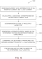
- FIG. 10 is a flow diagram of an exemplary method 1000 for use with a UPS system, such as system 300 (shown in FIG. 3 ).
- method 1000 is at least partially performed by a controller (e.g., controller 200, shown in FIG. 3 ).
- controller 200 shown in FIG. 3
- method 1000 includes additional, fewer, or alternative steps, including those described elsewhere herein.
Landscapes
- Engineering & Computer Science (AREA)
- Power Engineering (AREA)
- Business, Economics & Management (AREA)
- Emergency Management (AREA)
- Physics & Mathematics (AREA)
- General Physics & Mathematics (AREA)
- Inverter Devices (AREA)
- Stand-By Power Supply Arrangements (AREA)
Claims (9)
- Steuerung (200) zur Identifizierung eines Fehlerorts in einem unterbrechungsfreien Stromversorgungssystem (USV-System) (100, 300) das eine Vielzahl von USVs (102, 104, 106, 108, 302, 304, 306) und einen Ringbus (118, 314, 410, 510) umfasst. Jede der USVs (102, 104, 106, 108, 302, 304, 306) ist über einen statischen Schalter (340, 342, 344, 408) aus einer Mehrzahl von statischen Schaltern (340, 342, 344, 408) mit dem Ringbus (118, 314, 410, 510) verbunden. Jedes USV-System (100, 300) umfasst einen Wechselrichter (307), der ein Wandlermodul (602), eine Ausgangsdrossel (604), die zwischen dem Ausgang des Wandlermoduls (602) und einem Ausgangsknoten des Wechselrichters (307) angeschlossen ist, sowie einen Ausgangskondensator (606), der zwischen dem Ausgangsknoten des Wechselrichters (307) und Masse geschaltet ist, enthält. Die Steuerung (200) ist kommunikativ mit einem ersten statischen Schalter (340, 342, 344, 408) aus der Mehrzahl von statischen Schaltern (340, 342, 344, 408) gekoppelt. Der erste statische Schalter (340, 342, 344, 408) ist zwischen einer ersten USV (102, 302) der Vielzahl von USVs (102, 104, 106, 108, 302, 304, 306) und dem Ringbus (118, 314, 410, 510) geschaltet. Die Steuerung (200) ist so ausgelegt, dass sie Folgendes ausführen kann:Empfangen von aktuellen Daten, die einen Wechselrichterstrom der ersten USV (102, 302) darstellen, der zwischen der Ausgangsdrossel (604) und dem Ausgangsknoten des Wechselrichters (307) gemessen wird, und einen Laststrom, der von der ersten USV (102, 302) an den Ringbus (118, 314, 410, 510) geliefert wird;dadurch gekennzeichnet, dass die Steuerung (200) ferner so betreibbar ist, dass sie für die erste USV (102, 302) Folgendes ausführt:Berechnen einer Stromdifferenz zwischen dem Wechselrichterstrom und dem Laststrom;Bestimmen einer Spannung des Ausgangskondensators (606);Berechnen eines abgeleiteten Stroms auf der Grundlage der bestimmten Spannung und einer vorbestimmten Kapazität des Ausgangskondensators (606);Berechnen einer Differenz zwischen der Stromdifferenz und dem abgeleiteten Strom;Vergleichen der Differenz mit einem vorbestimmten Schwellenwert;den Fehlerort als (i) an der ersten USV (102, 302) liegend zu identifizieren, wenn die Differenz den vorbestimmten Schwellenwert überschreitet, oder (ii) an einem Ort außerhalb der ersten USV (102, 302) liegend zu identifizieren, wenn die Differenz innerhalb des vorbestimmten Schwellenwerts liegt; undden ersten statischen Schalter (340, 342, 344, 408) auf der Grundlage des identifizierten Fehlerorts zu steuern.
- Steuerung (200) gemäß Anspruch 1, wobei die Steuerung (200) ferner so betreibbar ist, dass sie einen Leistungsschalter (338) des USV-Systems (100, 300) steuert, um den ermittelten Fehlerort zu isolieren.
- Steuerung (200) gemäß Anspruch 1, wobei die Steuerung (200) ferner so betreibbar ist, dass sie:von der ersten USV (102, 302) ein Warnsignal zu empfangen, das anzeigt, dass das Wandlermodul (602) einen USV-Fehlerzustand an der ersten USV (102, 302) nicht verursacht hat; undden ersten statischen Schalter (340, 342, 344, 408) so zu steuern, dass er sich als Reaktion auf das Warnsignal schließt.
- Steuerung (200) gemäß Anspruch 1, wobei die Steuerung (200) ferner so betreibbar ist, dass sie den ersten statischen Schalter (340, 342, 344, 408) so steuert, dass er sich schließt, wenn sich der ermittelte Fehlerort an der ersten USV (102, 302) befindet.
- Unterbrechungsfreie Stromversorgung (USV) (100, 300), umfassend:eine Vielzahl von USVs (102, 104, 106, 302, 304, 306);eine Vielzahl von statischen Schaltern (340, 342, 344, 408);einem Ringbus (118, 314, 410, 510); undund einer Steuerung (200) gemäß einem der vorstehenden Ansprüche,wobei jede der Mehrzahl von USVs (102, 104, 106, 108, 302, 304, 306) über einen statischen Schalter (340, 342, 344, 408) der Mehrzahl von statischen Schaltern (340, 342, 344, 408) ausgewählt wird, wobei jedes USV-System (100, 300) einen Wechselrichter (307) umfasst, der ein Wandlermodul (602), eine Ausgangsdrossel (604), die zwischen einem Ausgang des Wandlermoduls (602) und einem Ausgangsknoten des Wechselrichters (307) angeschlossen ist, und einen Ausgangskondensator (606), der zwischen dem Ausgangsknoten des Wechselrichters (307) und Masse angeschlossen ist, wobei die Steuereinheit (200) kommunikativ mit einem ersten statischen Schalter (340, 342, 344, 408) der Mehrzahl von statischen Schaltern (340, 342, 344, 408) gekoppelt ist, der erste statische Schalter (340, 342, 344, 408) zwischen einer ersten USV (102, 302) der Mehrzahl von USVs (102, 104, 106, 108, 302, 304, 306) und dem Ringbus (118, 314, 410, 510).
- Das USV-System (100, 300) gemäß Anspruch 5, das außerdem einen von der Steuerung (200) bedienbaren Schutzschalter (338) umfasst.
- Verfahren (1000) zum Identifizieren eines Fehlerorts in einem unterbrechungsfreien Stromversorgungssystem (USV-System) (100, 300), das eine Vielzahl von USVs (102, 104, 106, 108, 302, 304, 306) und einen Ringbus (118, 314, 410, 510 ), wobei jede der mehreren USV (102, 104, 106, 108, 302, 304, 306) über einen statischen Schalter (340, 342, 344, 408) einer Mehrzahl von statischen Schaltern (340, 342, 344, 408), wobei jedes USV-System (100, 300) einen Wechselrichter (307) umfasst, der ein Wandlermodul (602), eine Ausgangsdrossel (604), die zwischen einem Ausgang des Wandlermoduls (602) und einem Ausgangsknoten des Wechselrichters (307) angeschlossen ist, und einen Ausgangskondensator (606), der zwischen dem Ausgangsknoten des Wechselrichters (307) und Erde geschaltet ist, wobei die Steuereinheit (200) kommunikativ mit einem ersten statischen Schalter (340, 342, 344, 408) der Vielzahl von statischen Schaltern (340, 342, 344, 408) gekoppelt ist, der erste statische Schalter (340, 342, 344, 408) zwischen einer ersten USV (102, 302) der Vielzahl von USVs (102, 104, 106, 108, 302, 304, 306) und dem Ringbus (118, 314, 410, 510), wobei das Verfahren umfasst:Empfangen (1002) durch den Controller (200) von Stromdaten, die sowohl einen Wechselrichterstrom der ersten USV (102, 302), gemessen zwischen der Ausgangsdrossel (604) und dem Ausgangsknoten des Wechselrichters (307), als auch einen Laststrom umfassen, der von der ersten USV (102, 302) an den Ringbus (118, 314, 410, 510) geliefert wird;und dadurch gekennzeichnet, dass das Verfahren ferner umfasst, dass für die erste USV (102, 302) Folgendes durchgeführt wird:Berechnen (1004) einer Stromdifferenz zwischen dem Wechselrichterstrom und dem Laststrom;Bestimmen (1006) einer Spannung des Ausgangskondensators (606);Berechnen (1008) durch den Controller (200) eines abgeleiteten Stroms auf der Grundlage der ermittelten Spannung und einer vorbestimmten Kapazität des Ausgangskondensators (606);Vergleichen (1010) der Stromdifferenz und des abgeleiteten Stroms, um den Fehlerort zu identifizieren, durch:Berechnung der Differenz zwischen der Stromdifferenz und dem abgeleiteten Strom;Vergleichen der Differenz mit einem vorbestimmten Schwellenwert; undIdentifizieren des Fehlerortes als (i) an der ersten USV (102, 302), wenn die Differenz den vorbestimmten Schwellenwert überschreitet, oder (ii) an einem Ort außerhalb der ersten USV (102, 302), wenn die Differenz innerhalb des vorbestimmten Schwellenwerts liegt; undSteuern (1012) durch die Steuerung (200) den ersten statischen Schalter (340, 342, 344, 408) basierend auf dem identifizierten Fehlerort.
- Verfahren (1000) gemäß Anspruch 7, wobei die Steuerung des ersten statischen Schalters (340, 342, 344, 408) ferner umfasst: Schließen des ersten statischen Schalters (340, 342, 344, 408) durch die Steuerung (200), wenn sich der identifizierte Fehlerort an der ersten USV (102, 302) befindet.
- Verfahren (1000) gemäß Anspruch 7, wobei die Steuerung des ersten statischen Schalters (340, 342, 344, 408) ferner Folgendes umfasst:
Steuerung eines Schaltungsunterbrechers (338) des USV-Systems (100, 300) durch die Steuerung (200), um den identifizierten Fehlerort zu isolieren, wenn der identifizierte Fehlerort außerhalb der ersten USV liegt.
Applications Claiming Priority (1)
| Application Number | Priority Date | Filing Date | Title |
|---|---|---|---|
| US15/263,821 US10284008B2 (en) | 2016-09-13 | 2016-09-13 | Isolated parallel ups system with fault location detection |
Publications (2)
| Publication Number | Publication Date |
|---|---|
| EP3293852A1 EP3293852A1 (de) | 2018-03-14 |
| EP3293852B1 true EP3293852B1 (de) | 2025-07-02 |
Family
ID=59745749
Family Applications (1)
| Application Number | Title | Priority Date | Filing Date |
|---|---|---|---|
| EP17188222.8A Active EP3293852B1 (de) | 2016-09-13 | 2017-08-29 | Isoliertes paralleles usv-system mit fehlerorterkennung |
Country Status (3)
| Country | Link |
|---|---|
| US (1) | US10284008B2 (de) |
| EP (1) | EP3293852B1 (de) |
| CN (1) | CN107819357B (de) |
Families Citing this family (18)
| Publication number | Priority date | Publication date | Assignee | Title |
|---|---|---|---|---|
| US10284007B2 (en) * | 2014-10-23 | 2019-05-07 | Abb Schweiz Ag | Protection methods and switches in uninterruptible power supply systems |
| US10461577B2 (en) * | 2017-08-23 | 2019-10-29 | Schneider Electric It Corporation | Inverter paralleling control system and method |
| US11183871B2 (en) * | 2019-01-28 | 2021-11-23 | Abb Schweiz Ag | Technologies for static transfer switch load transfer for catcher uninterruptible power supply systems |
| AU2020393924B2 (en) * | 2019-11-27 | 2023-08-10 | Equinix, Inc. | Reserve bus distribution system testing |
| CN110943528B (zh) * | 2019-11-28 | 2021-11-16 | 广西电网有限责任公司南宁供电局 | 一种不间断电源学习型负载电流估计系统 |
| CN110988563B (zh) * | 2019-12-23 | 2022-04-01 | 厦门理工学院 | 一种ups故障检测方法、装置、设备和存储介质 |
| CA3166051A1 (en) * | 2020-01-09 | 2021-07-15 | Abb Schweiz Ag | Apparatus and method for flux management in impedance isolation single conversion (zisc) based ups system |
| CN112968516B (zh) * | 2021-02-20 | 2023-06-09 | 国网重庆市电力公司电力科学研究院 | 一种基于神经网络的并联ups系统状态反馈控制方法 |
| CN113341246B (zh) * | 2021-05-24 | 2024-02-06 | 国网陕西省电力公司西安供电公司 | 基于电容校准的消弧线圈测试装置及测试方法 |
| CN113791304B (zh) * | 2021-08-23 | 2024-04-09 | 珠海许继芝电网自动化有限公司 | 故障类型及故障区段识别方法 |
| US12341333B2 (en) * | 2021-09-09 | 2025-06-24 | Clemson University Research Foundation | Topology agnostic detection and location of fault in DC microgrid using local measurements |
| CN113936830B (zh) * | 2021-09-22 | 2024-09-20 | 广东核电合营有限公司 | 一种核电厂发电机组状态控制方法及电子设备 |
| US11955835B2 (en) | 2021-10-13 | 2024-04-09 | Abb Schweiz Ag | Method and control to integrate fuel cells in datacenters with ring-bus architecture |
| CN115219921B (zh) * | 2022-08-19 | 2023-04-11 | 北京索英电气技术股份有限公司 | 电芯测试过程中的监控方法、装置及电芯测试监控系统 |
| CN115575848B (zh) * | 2022-10-11 | 2025-07-29 | 厦门市爱维达电子有限公司 | 应用于ups并机系统断路故障的检测方法、设备及介质 |
| US12081064B2 (en) * | 2022-11-15 | 2024-09-03 | Google Llc | System and method for transitioning to backup power pooling |
| CN115825796A (zh) * | 2022-11-18 | 2023-03-21 | 深圳供电局有限公司 | 一种ups逆变电源故障自愈控制方法及装置 |
| US12113396B1 (en) * | 2023-03-13 | 2024-10-08 | Abb Schweiz Ag | Fuel cell powered ring bus architectures |
Family Cites Families (41)
| Publication number | Priority date | Publication date | Assignee | Title |
|---|---|---|---|---|
| FR2663175A1 (fr) | 1990-06-12 | 1991-12-13 | Merlin Gerin | Commutateur statique. |
| US5315533A (en) | 1991-05-17 | 1994-05-24 | Best Power Technology, Inc. | Back-up uninterruptible power system |
| JP3322060B2 (ja) * | 1995-03-23 | 2002-09-09 | 株式会社日立製作所 | 発電プラント及び発電プラントの制御装置 |
| US5745355A (en) | 1996-06-25 | 1998-04-28 | Exide Electronics Corporation | Wireless selective tripping of AC power systems connected in parallel |
| JP2998711B2 (ja) * | 1997-08-19 | 2000-01-11 | 日新電機株式会社 | 瞬低対策機能付き分散電源装置 |
| US6275958B1 (en) | 1998-10-28 | 2001-08-14 | International Business Machines Corporation | Fault detection in a redundant power converter |
| US6407899B1 (en) | 2000-03-07 | 2002-06-18 | International Business Machines Corporation | Fault detection in a redundant power converter |
| EP1160965B1 (de) | 2000-06-01 | 2004-08-25 | Liebert Corporation | Vorrichtung und Verfahren für eine schnelle Fehlererkennung und Übertragung in eine geräteinteraktive unterbrechungsfreie Stromversorgung |
| CA2496365C (en) * | 2005-02-04 | 2010-06-22 | Always "On" Ups Systems Inc. | Panel and breaker for distributing ups power |
| US7265458B2 (en) | 2005-04-08 | 2007-09-04 | Eaton Power Quality Corporation | Apparatus and methods for coordinated static switch operations for load transfers in uninterruptible power supply systems |
| US7613974B2 (en) | 2006-03-24 | 2009-11-03 | Ics Triplex Technology Limited | Fault detection method and apparatus |
| US8581723B2 (en) | 2006-05-19 | 2013-11-12 | Schweitzer Engineering Laboratories Inc | Fault detection using phase comparison |
| EP1890371A1 (de) | 2006-08-03 | 2008-02-20 | Michael J. Mosman | USV-Systemkonfiguration mit parallelen und von einander unabhängigen Modulen |
| US7403364B2 (en) | 2006-11-30 | 2008-07-22 | Eaton Corporation | Power system fault characterization using transformed values |
| US8513951B2 (en) | 2008-07-30 | 2013-08-20 | Northrop Grumman Systems Corporation | Method and apparatus for fast fault detection |
| US8060321B2 (en) | 2008-08-15 | 2011-11-15 | Liebert Corporation | System and method for detecting an electrical short across a static switch of an uninterruptible power supply |
| KR101037713B1 (ko) | 2010-03-03 | 2011-05-27 | 숭실대학교산학협력단 | 고장전류 제한 및 무정전 전원공급을 위한 초전도 전류제한기 |
| EP2659319A4 (de) * | 2010-11-19 | 2017-07-26 | Google, Inc. | Aufteilung einer flexiblen funktionalität in durch intelligente thermostate gesteuerten hvac-systemen |
| US9093860B2 (en) | 2011-09-19 | 2015-07-28 | Schneider Electric It Corporation | Fault detection for parallel inverters system |
| EP2600491A1 (de) * | 2011-12-01 | 2013-06-05 | AEG Power Solutions B.V. | Anordnung zur unterbrechungsfreien Stromversorgung |
| US9170568B1 (en) | 2012-01-09 | 2015-10-27 | Solidstate Controls, Llc | Fail-safe static switch |
| US9160202B2 (en) | 2012-01-31 | 2015-10-13 | General Electric Company | Control system for uninterruptible power supplies |
| US9236768B2 (en) | 2012-01-31 | 2016-01-12 | Lorenzo Giuntini | Systems, methods, and devices for control of parallel uninterruptible power supplies |
| JP2013246155A (ja) | 2012-05-29 | 2013-12-09 | Fujitsu Ltd | 故障検出回路、故障検出方法、及び電子機器 |
| ITMI20121191A1 (it) | 2012-07-06 | 2014-01-07 | Gen Electric | Sistemi, procedimenti, e dispositivi per la stima della capacita' di condensatori di potenza |
| CN102790418A (zh) * | 2012-08-10 | 2012-11-21 | 广东易事特电源股份有限公司 | 模块化ups及多充电器并联逻辑控制方法 |
| CN102801196B (zh) | 2012-08-15 | 2014-06-11 | 佛山市柏克新能科技股份有限公司 | 一种具有维修保护功能的ups电源 |
| US9531288B2 (en) | 2012-11-21 | 2016-12-27 | Liebert Corporation | Systems and methods for balancing UPS output voltages during transitions between operating modes |
| US9239364B2 (en) | 2012-12-18 | 2016-01-19 | Eaton Corporation | Methods of testing unInterruptible power supply (UPS) systems with multiple UPS modules |
| WO2014098800A1 (en) | 2012-12-18 | 2014-06-26 | Schneider Electric It Corporation | Method and apparatus for detecting failed capacitors in power devices |
| CN203406551U (zh) * | 2013-07-02 | 2014-01-22 | 保定鼎阳电力科技发展有限公司 | 一种运行安全可靠的空气绝缘环网柜 |
| US9882424B2 (en) | 2014-02-21 | 2018-01-30 | General Electric Company | Redundant uninterruptible power supply systems |
| US9685820B2 (en) | 2014-03-11 | 2017-06-20 | General Electric Company | Redundant uninterruptible power supply systems |
| US9705360B2 (en) | 2014-03-11 | 2017-07-11 | General Electric Company | Redundant uninterruptible power supply systems |
| CN105006878B (zh) * | 2014-03-13 | 2020-06-30 | Abb瑞士股份有限公司 | 在不可中断电源系统中提供增加的故障电流能力的系统和方法 |
| US9735616B2 (en) * | 2014-03-13 | 2017-08-15 | General Electric Company | Systems and methods for providing increased fault current capability in uninterruptible power supply systems |
| CN103972978B (zh) * | 2014-05-07 | 2016-08-24 | 厦门科华恒盛股份有限公司 | 不间断电源电池共用系统及其控制方法 |
| US10284007B2 (en) | 2014-10-23 | 2019-05-07 | Abb Schweiz Ag | Protection methods and switches in uninterruptible power supply systems |
| CN204258411U (zh) | 2014-11-21 | 2015-04-08 | 厦门朗臣电子科技有限公司 | 一种智能ups电源装置 |
| CN204905997U (zh) * | 2015-09-15 | 2015-12-23 | 江苏省电力公司苏州供电公司 | 双电源转切装置 |
| US10199861B2 (en) | 2016-09-13 | 2019-02-05 | Abb Schweiz Ag | Isolated parallel UPS system with choke bypass switch |
-
2016
- 2016-09-13 US US15/263,821 patent/US10284008B2/en active Active
-
2017
- 2017-08-29 EP EP17188222.8A patent/EP3293852B1/de active Active
- 2017-09-13 CN CN201710826953.7A patent/CN107819357B/zh active Active
Also Published As
| Publication number | Publication date |
|---|---|
| CN107819357A (zh) | 2018-03-20 |
| CN107819357B (zh) | 2023-01-24 |
| US20180076658A1 (en) | 2018-03-15 |
| EP3293852A1 (de) | 2018-03-14 |
| US10284008B2 (en) | 2019-05-07 |
Similar Documents
| Publication | Publication Date | Title |
|---|---|---|
| US11355957B2 (en) | Isolated parallel UPS system with choke bypass switch | |
| EP3293852B1 (de) | Isoliertes paralleles usv-system mit fehlerorterkennung | |
| US10992219B2 (en) | Power conversion device | |
| US8624437B2 (en) | Power conversion system and method | |
| US7129599B2 (en) | Dual feed power supply systems with enhanced power quality | |
| US9780556B2 (en) | Voltage sourced converter with semiconductor modules handling a DC current fault | |
| JP5645864B2 (ja) | 三相不平衡抑制システム | |
| US9553441B2 (en) | Method and apparatus for protecting an intermediate circuit capacitor in a power converter | |
| CN105553086B (zh) | 不间断电力供应系统中的保护方法和开关 | |
| WO2004030178A1 (en) | System for providing assured power to a critical load | |
| CN105870893B (zh) | 微网群的保护配置方法 | |
| JPWO2018092303A1 (ja) | 電力変換装置 | |
| US20180034316A1 (en) | Device for commanding/controlling a source changeover switch | |
| US11909201B2 (en) | Multi-terminal DC power transmission system, common control device thereof, and fault recovery method for multi-terminal DC power transmission system | |
| US10951057B1 (en) | Reliable power module for improved substation device availability | |
| US11476701B2 (en) | Uninterruptable power supply device | |
| Lazzari et al. | Selectivity and security of DC microgrid under line-to-ground fault | |
| JP2003333862A (ja) | 電力変換装置 | |
| WO2020068024A2 (en) | The smart circuit breaker for grid connected residential photovoltaic systems | |
| US11967858B2 (en) | Static transfer switch, and ups module to which static transfer switch is applied | |
| US12431732B2 (en) | Uninterruptible power supply apparatus | |
| CN108808835A (zh) | 一种ups故障保护电路及ups装置 | |
| Fiorina | Uninterruptible static power supplies and the protection of persons |
Legal Events
| Date | Code | Title | Description |
|---|---|---|---|
| PUAI | Public reference made under article 153(3) epc to a published international application that has entered the european phase |
Free format text: ORIGINAL CODE: 0009012 |
|
| STAA | Information on the status of an ep patent application or granted ep patent |
Free format text: STATUS: THE APPLICATION HAS BEEN PUBLISHED |
|
| AK | Designated contracting states |
Kind code of ref document: A1 Designated state(s): AL AT BE BG CH CY CZ DE DK EE ES FI FR GB GR HR HU IE IS IT LI LT LU LV MC MK MT NL NO PL PT RO RS SE SI SK SM TR |
|
| AX | Request for extension of the european patent |
Extension state: BA ME |
|
| STAA | Information on the status of an ep patent application or granted ep patent |
Free format text: STATUS: REQUEST FOR EXAMINATION WAS MADE |
|
| 17P | Request for examination filed |
Effective date: 20190108 |
|
| RBV | Designated contracting states (corrected) |
Designated state(s): AL AT BE BG CH CY CZ DE DK EE ES FI FR GB GR HR HU IE IS IT LI LT LU LV MC MK MT NL NO PL PT RO RS SE SI SK SM TR |
|
| RAP1 | Party data changed (applicant data changed or rights of an application transferred) |
Owner name: ABB SCHWEIZ AG |
|
| STAA | Information on the status of an ep patent application or granted ep patent |
Free format text: STATUS: EXAMINATION IS IN PROGRESS |
|
| 17Q | First examination report despatched |
Effective date: 20201007 |
|
| RAP3 | Party data changed (applicant data changed or rights of an application transferred) |
Owner name: ABB SCHWEIZ AG |
|
| GRAP | Despatch of communication of intention to grant a patent |
Free format text: ORIGINAL CODE: EPIDOSNIGR1 |
|
| STAA | Information on the status of an ep patent application or granted ep patent |
Free format text: STATUS: GRANT OF PATENT IS INTENDED |
|
| RIC1 | Information provided on ipc code assigned before grant |
Ipc: G01R 31/40 20140101ALI20250114BHEP Ipc: G01R 31/08 20060101ALI20250114BHEP Ipc: H02J 9/06 20060101AFI20250114BHEP |
|
| INTG | Intention to grant announced |
Effective date: 20250123 |
|
| GRAS | Grant fee paid |
Free format text: ORIGINAL CODE: EPIDOSNIGR3 |
|
| GRAA | (expected) grant |
Free format text: ORIGINAL CODE: 0009210 |
|
| STAA | Information on the status of an ep patent application or granted ep patent |
Free format text: STATUS: THE PATENT HAS BEEN GRANTED |
|
| AK | Designated contracting states |
Kind code of ref document: B1 Designated state(s): AL AT BE BG CH CY CZ DE DK EE ES FI FR GB GR HR HU IE IS IT LI LT LU LV MC MK MT NL NO PL PT RO RS SE SI SK SM TR |
|
| REG | Reference to a national code |
Ref country code: GB Ref legal event code: FG4D |
|
| REG | Reference to a national code |
Ref country code: CH Ref legal event code: EP |
|
| REG | Reference to a national code |
Ref country code: DE Ref legal event code: R096 Ref document number: 602017090238 Country of ref document: DE |
|
| REG | Reference to a national code |
Ref country code: IE Ref legal event code: FG4D |
|
| PGFP | Annual fee paid to national office [announced via postgrant information from national office to epo] |
Ref country code: DE Payment date: 20250820 Year of fee payment: 9 |
|
| REG | Reference to a national code |
Ref country code: NL Ref legal event code: MP Effective date: 20250702 |
|
| PG25 | Lapsed in a contracting state [announced via postgrant information from national office to epo] |
Ref country code: PT Free format text: LAPSE BECAUSE OF FAILURE TO SUBMIT A TRANSLATION OF THE DESCRIPTION OR TO PAY THE FEE WITHIN THE PRESCRIBED TIME-LIMIT Effective date: 20251103 |
|
| PG25 | Lapsed in a contracting state [announced via postgrant information from national office to epo] |
Ref country code: NL Free format text: LAPSE BECAUSE OF FAILURE TO SUBMIT A TRANSLATION OF THE DESCRIPTION OR TO PAY THE FEE WITHIN THE PRESCRIBED TIME-LIMIT Effective date: 20250702 |
|
| REG | Reference to a national code |
Ref country code: AT Ref legal event code: MK05 Ref document number: 1810399 Country of ref document: AT Kind code of ref document: T Effective date: 20250702 |
|
| PG25 | Lapsed in a contracting state [announced via postgrant information from national office to epo] |
Ref country code: IS Free format text: LAPSE BECAUSE OF FAILURE TO SUBMIT A TRANSLATION OF THE DESCRIPTION OR TO PAY THE FEE WITHIN THE PRESCRIBED TIME-LIMIT Effective date: 20251102 |
|
| PG25 | Lapsed in a contracting state [announced via postgrant information from national office to epo] |
Ref country code: NO Free format text: LAPSE BECAUSE OF FAILURE TO SUBMIT A TRANSLATION OF THE DESCRIPTION OR TO PAY THE FEE WITHIN THE PRESCRIBED TIME-LIMIT Effective date: 20251002 |
|
| REG | Reference to a national code |
Ref country code: LT Ref legal event code: MG9D |
|
| PG25 | Lapsed in a contracting state [announced via postgrant information from national office to epo] |
Ref country code: AT Free format text: LAPSE BECAUSE OF FAILURE TO SUBMIT A TRANSLATION OF THE DESCRIPTION OR TO PAY THE FEE WITHIN THE PRESCRIBED TIME-LIMIT Effective date: 20250702 |
|
| PG25 | Lapsed in a contracting state [announced via postgrant information from national office to epo] |
Ref country code: FI Free format text: LAPSE BECAUSE OF FAILURE TO SUBMIT A TRANSLATION OF THE DESCRIPTION OR TO PAY THE FEE WITHIN THE PRESCRIBED TIME-LIMIT Effective date: 20250702 |
|
| PG25 | Lapsed in a contracting state [announced via postgrant information from national office to epo] |
Ref country code: HR Free format text: LAPSE BECAUSE OF FAILURE TO SUBMIT A TRANSLATION OF THE DESCRIPTION OR TO PAY THE FEE WITHIN THE PRESCRIBED TIME-LIMIT Effective date: 20250702 |
|
| PG25 | Lapsed in a contracting state [announced via postgrant information from national office to epo] |
Ref country code: GR Free format text: LAPSE BECAUSE OF FAILURE TO SUBMIT A TRANSLATION OF THE DESCRIPTION OR TO PAY THE FEE WITHIN THE PRESCRIBED TIME-LIMIT Effective date: 20251003 |
|
| PG25 | Lapsed in a contracting state [announced via postgrant information from national office to epo] |
Ref country code: SE Free format text: LAPSE BECAUSE OF FAILURE TO SUBMIT A TRANSLATION OF THE DESCRIPTION OR TO PAY THE FEE WITHIN THE PRESCRIBED TIME-LIMIT Effective date: 20250702 Ref country code: CZ Free format text: LAPSE BECAUSE OF FAILURE TO SUBMIT A TRANSLATION OF THE DESCRIPTION OR TO PAY THE FEE WITHIN THE PRESCRIBED TIME-LIMIT Effective date: 20250702 |
|
| PG25 | Lapsed in a contracting state [announced via postgrant information from national office to epo] |
Ref country code: LV Free format text: LAPSE BECAUSE OF FAILURE TO SUBMIT A TRANSLATION OF THE DESCRIPTION OR TO PAY THE FEE WITHIN THE PRESCRIBED TIME-LIMIT Effective date: 20250702 |
|
| PG25 | Lapsed in a contracting state [announced via postgrant information from national office to epo] |
Ref country code: BG Free format text: LAPSE BECAUSE OF FAILURE TO SUBMIT A TRANSLATION OF THE DESCRIPTION OR TO PAY THE FEE WITHIN THE PRESCRIBED TIME-LIMIT Effective date: 20250702 Ref country code: PL Free format text: LAPSE BECAUSE OF FAILURE TO SUBMIT A TRANSLATION OF THE DESCRIPTION OR TO PAY THE FEE WITHIN THE PRESCRIBED TIME-LIMIT Effective date: 20250702 |
|
| PG25 | Lapsed in a contracting state [announced via postgrant information from national office to epo] |
Ref country code: RS Free format text: LAPSE BECAUSE OF FAILURE TO SUBMIT A TRANSLATION OF THE DESCRIPTION OR TO PAY THE FEE WITHIN THE PRESCRIBED TIME-LIMIT Effective date: 20251002 |
|
| PG25 | Lapsed in a contracting state [announced via postgrant information from national office to epo] |
Ref country code: ES Free format text: LAPSE BECAUSE OF FAILURE TO SUBMIT A TRANSLATION OF THE DESCRIPTION OR TO PAY THE FEE WITHIN THE PRESCRIBED TIME-LIMIT Effective date: 20250702 |
|
| PG25 | Lapsed in a contracting state [announced via postgrant information from national office to epo] |
Ref country code: RO Free format text: LAPSE BECAUSE OF FAILURE TO SUBMIT A TRANSLATION OF THE DESCRIPTION OR TO PAY THE FEE WITHIN THE PRESCRIBED TIME-LIMIT Effective date: 20250702 |