EP3293537B1 - Systems and methods for adding functional grid elements to stochastic sparse tree grids for spatial filtering - Google Patents
Systems and methods for adding functional grid elements to stochastic sparse tree grids for spatial filtering Download PDFInfo
- Publication number
- EP3293537B1 EP3293537B1 EP17181686.1A EP17181686A EP3293537B1 EP 3293537 B1 EP3293537 B1 EP 3293537B1 EP 17181686 A EP17181686 A EP 17181686A EP 3293537 B1 EP3293537 B1 EP 3293537B1
- Authority
- EP
- European Patent Office
- Prior art keywords
- signal
- data
- data block
- array
- computing device
- Prior art date
- Legal status (The legal status is an assumption and is not a legal conclusion. Google has not performed a legal analysis and makes no representation as to the accuracy of the status listed.)
- Active
Links
- 238000000034 method Methods 0.000 title claims description 138
- 238000001914 filtration Methods 0.000 title claims description 45
- 239000013598 vector Substances 0.000 claims description 112
- 230000008859 change Effects 0.000 claims description 19
- 238000000926 separation method Methods 0.000 claims description 14
- 230000001052 transient effect Effects 0.000 claims description 9
- 238000003491 array Methods 0.000 claims description 8
- 230000001133 acceleration Effects 0.000 claims description 5
- 238000012545 processing Methods 0.000 description 85
- 230000008569 process Effects 0.000 description 28
- 238000003672 processing method Methods 0.000 description 17
- 238000010586 diagram Methods 0.000 description 10
- 230000006870 function Effects 0.000 description 10
- 238000005259 measurement Methods 0.000 description 10
- 238000012805 post-processing Methods 0.000 description 10
- 238000013475 authorization Methods 0.000 description 7
- 239000007787 solid Substances 0.000 description 7
- 238000001514 detection method Methods 0.000 description 6
- 238000013459 approach Methods 0.000 description 5
- 238000004891 communication Methods 0.000 description 5
- 238000007781 pre-processing Methods 0.000 description 4
- 239000011159 matrix material Substances 0.000 description 3
- 230000000704 physical effect Effects 0.000 description 3
- 230000007480 spreading Effects 0.000 description 3
- 238000007619 statistical method Methods 0.000 description 3
- 230000008901 benefit Effects 0.000 description 2
- 230000003247 decreasing effect Effects 0.000 description 2
- 230000000694 effects Effects 0.000 description 2
- 230000004927 fusion Effects 0.000 description 2
- 230000004048 modification Effects 0.000 description 2
- 238000012986 modification Methods 0.000 description 2
- 230000002093 peripheral effect Effects 0.000 description 2
- 230000003252 repetitive effect Effects 0.000 description 2
- XLYOFNOQVPJJNP-UHFFFAOYSA-N water Substances O XLYOFNOQVPJJNP-UHFFFAOYSA-N 0.000 description 2
- 101100228469 Caenorhabditis elegans exp-1 gene Proteins 0.000 description 1
- 230000032683 aging Effects 0.000 description 1
- 230000003321 amplification Effects 0.000 description 1
- 230000005540 biological transmission Effects 0.000 description 1
- 238000004364 calculation method Methods 0.000 description 1
- 239000003086 colorant Substances 0.000 description 1
- 230000003750 conditioning effect Effects 0.000 description 1
- 239000000470 constituent Substances 0.000 description 1
- 229910003460 diamond Inorganic materials 0.000 description 1
- 239000010432 diamond Substances 0.000 description 1
- 230000003292 diminished effect Effects 0.000 description 1
- 230000006872 improvement Effects 0.000 description 1
- 230000003993 interaction Effects 0.000 description 1
- 230000002452 interceptive effect Effects 0.000 description 1
- 230000001788 irregular Effects 0.000 description 1
- 238000013507 mapping Methods 0.000 description 1
- 230000007246 mechanism Effects 0.000 description 1
- 238000003199 nucleic acid amplification method Methods 0.000 description 1
- 230000004044 response Effects 0.000 description 1
- 230000035945 sensitivity Effects 0.000 description 1
- 238000012800 visualization Methods 0.000 description 1
- 230000002618 waking effect Effects 0.000 description 1
Images


Classifications
-
- G—PHYSICS
- G01—MEASURING; TESTING
- G01S—RADIO DIRECTION-FINDING; RADIO NAVIGATION; DETERMINING DISTANCE OR VELOCITY BY USE OF RADIO WAVES; LOCATING OR PRESENCE-DETECTING BY USE OF THE REFLECTION OR RERADIATION OF RADIO WAVES; ANALOGOUS ARRANGEMENTS USING OTHER WAVES
- G01S7/00—Details of systems according to groups G01S13/00, G01S15/00, G01S17/00
- G01S7/02—Details of systems according to groups G01S13/00, G01S15/00, G01S17/00 of systems according to group G01S13/00
- G01S7/28—Details of pulse systems
- G01S7/285—Receivers
- G01S7/292—Extracting wanted echo-signals
- G01S7/2923—Extracting wanted echo-signals based on data belonging to a number of consecutive radar periods
-
- G—PHYSICS
- G01—MEASURING; TESTING
- G01S—RADIO DIRECTION-FINDING; RADIO NAVIGATION; DETERMINING DISTANCE OR VELOCITY BY USE OF RADIO WAVES; LOCATING OR PRESENCE-DETECTING BY USE OF THE REFLECTION OR RERADIATION OF RADIO WAVES; ANALOGOUS ARRANGEMENTS USING OTHER WAVES
- G01S5/00—Position-fixing by co-ordinating two or more direction or position line determinations; Position-fixing by co-ordinating two or more distance determinations
- G01S5/02—Position-fixing by co-ordinating two or more direction or position line determinations; Position-fixing by co-ordinating two or more distance determinations using radio waves
- G01S5/12—Position-fixing by co-ordinating two or more direction or position line determinations; Position-fixing by co-ordinating two or more distance determinations using radio waves by co-ordinating position lines of different shape, e.g. hyperbolic, circular, elliptical or radial
-
- G—PHYSICS
- G06—COMPUTING; CALCULATING OR COUNTING
- G06V—IMAGE OR VIDEO RECOGNITION OR UNDERSTANDING
- G06V10/00—Arrangements for image or video recognition or understanding
- G06V10/40—Extraction of image or video features
- G06V10/44—Local feature extraction by analysis of parts of the pattern, e.g. by detecting edges, contours, loops, corners, strokes or intersections; Connectivity analysis, e.g. of connected components
- G06V10/443—Local feature extraction by analysis of parts of the pattern, e.g. by detecting edges, contours, loops, corners, strokes or intersections; Connectivity analysis, e.g. of connected components by matching or filtering
-
- G—PHYSICS
- G01—MEASURING; TESTING
- G01S—RADIO DIRECTION-FINDING; RADIO NAVIGATION; DETERMINING DISTANCE OR VELOCITY BY USE OF RADIO WAVES; LOCATING OR PRESENCE-DETECTING BY USE OF THE REFLECTION OR RERADIATION OF RADIO WAVES; ANALOGOUS ARRANGEMENTS USING OTHER WAVES
- G01S13/00—Systems using the reflection or reradiation of radio waves, e.g. radar systems; Analogous systems using reflection or reradiation of waves whose nature or wavelength is irrelevant or unspecified
- G01S13/02—Systems using reflection of radio waves, e.g. primary radar systems; Analogous systems
- G01S13/50—Systems of measurement based on relative movement of target
- G01S13/52—Discriminating between fixed and moving objects or between objects moving at different speeds
- G01S13/56—Discriminating between fixed and moving objects or between objects moving at different speeds for presence detection
-
- G—PHYSICS
- G01—MEASURING; TESTING
- G01S—RADIO DIRECTION-FINDING; RADIO NAVIGATION; DETERMINING DISTANCE OR VELOCITY BY USE OF RADIO WAVES; LOCATING OR PRESENCE-DETECTING BY USE OF THE REFLECTION OR RERADIATION OF RADIO WAVES; ANALOGOUS ARRANGEMENTS USING OTHER WAVES
- G01S13/00—Systems using the reflection or reradiation of radio waves, e.g. radar systems; Analogous systems using reflection or reradiation of waves whose nature or wavelength is irrelevant or unspecified
- G01S13/02—Systems using reflection of radio waves, e.g. primary radar systems; Analogous systems
- G01S13/50—Systems of measurement based on relative movement of target
- G01S13/58—Velocity or trajectory determination systems; Sense-of-movement determination systems
- G01S13/62—Sense-of-movement determination
-
- G—PHYSICS
- G01—MEASURING; TESTING
- G01S—RADIO DIRECTION-FINDING; RADIO NAVIGATION; DETERMINING DISTANCE OR VELOCITY BY USE OF RADIO WAVES; LOCATING OR PRESENCE-DETECTING BY USE OF THE REFLECTION OR RERADIATION OF RADIO WAVES; ANALOGOUS ARRANGEMENTS USING OTHER WAVES
- G01S5/00—Position-fixing by co-ordinating two or more direction or position line determinations; Position-fixing by co-ordinating two or more distance determinations
- G01S5/02—Position-fixing by co-ordinating two or more direction or position line determinations; Position-fixing by co-ordinating two or more distance determinations using radio waves
- G01S5/0205—Details
- G01S5/0244—Accuracy or reliability of position solution or of measurements contributing thereto
-
- G—PHYSICS
- G01—MEASURING; TESTING
- G01S—RADIO DIRECTION-FINDING; RADIO NAVIGATION; DETERMINING DISTANCE OR VELOCITY BY USE OF RADIO WAVES; LOCATING OR PRESENCE-DETECTING BY USE OF THE REFLECTION OR RERADIATION OF RADIO WAVES; ANALOGOUS ARRANGEMENTS USING OTHER WAVES
- G01S7/00—Details of systems according to groups G01S13/00, G01S15/00, G01S17/00
- G01S7/02—Details of systems according to groups G01S13/00, G01S15/00, G01S17/00 of systems according to group G01S13/00
- G01S7/04—Display arrangements
- G01S7/046—Display arrangements using an intermediate storage device, e.g. a recording/reproducing device
-
- G—PHYSICS
- G06—COMPUTING; CALCULATING OR COUNTING
- G06F—ELECTRIC DIGITAL DATA PROCESSING
- G06F16/00—Information retrieval; Database structures therefor; File system structures therefor
- G06F16/20—Information retrieval; Database structures therefor; File system structures therefor of structured data, e.g. relational data
- G06F16/29—Geographical information databases
-
- G—PHYSICS
- G06—COMPUTING; CALCULATING OR COUNTING
- G06V—IMAGE OR VIDEO RECOGNITION OR UNDERSTANDING
- G06V10/00—Arrangements for image or video recognition or understanding
- G06V10/20—Image preprocessing
- G06V10/30—Noise filtering
-
- G—PHYSICS
- G06—COMPUTING; CALCULATING OR COUNTING
- G06V—IMAGE OR VIDEO RECOGNITION OR UNDERSTANDING
- G06V20/00—Scenes; Scene-specific elements
- G06V20/10—Terrestrial scenes
- G06V20/13—Satellite images
-
- G—PHYSICS
- G01—MEASURING; TESTING
- G01S—RADIO DIRECTION-FINDING; RADIO NAVIGATION; DETERMINING DISTANCE OR VELOCITY BY USE OF RADIO WAVES; LOCATING OR PRESENCE-DETECTING BY USE OF THE REFLECTION OR RERADIATION OF RADIO WAVES; ANALOGOUS ARRANGEMENTS USING OTHER WAVES
- G01S2205/00—Position-fixing by co-ordinating two or more direction or position line determinations; Position-fixing by co-ordinating two or more distance determinations
- G01S2205/01—Position-fixing by co-ordinating two or more direction or position line determinations; Position-fixing by co-ordinating two or more distance determinations specially adapted for specific applications
- G01S2205/03—Airborne
-
- G—PHYSICS
- G06—COMPUTING; CALCULATING OR COUNTING
- G06F—ELECTRIC DIGITAL DATA PROCESSING
- G06F2218/00—Aspects of pattern recognition specially adapted for signal processing
- G06F2218/02—Preprocessing
- G06F2218/04—Denoising
-
- H—ELECTRICITY
- H04—ELECTRIC COMMUNICATION TECHNIQUE
- H04W—WIRELESS COMMUNICATION NETWORKS
- H04W64/00—Locating users or terminals or network equipment for network management purposes, e.g. mobility management
Definitions
- the field of the disclosure relates generally to spatial filtering of signal data received by wide-area surveillance sensors, and, more specifically, to systems and methods for adding functional grid elements to stochastic sparse tree grids for spatial filtering.
- improved pre-processing front-end architectures generate signal data vectors having new characteristics and require more extensive processing systems and methods. Improvements in known spatial filtering systems and methods including denoising and blind source separation generate signal parameter vectors containing new characteristics and additional new information types. In order to efficiently generate useful deinterleaving information of signal parameter vectors during post-processing, such known spatial filtering systems and methods require substantially more complex processor architectures. Even with improved post-processing architectures, such known spatial filtering systems and methods suffer from diminished deinterleaving performance with new types of signal parameter vector data and non-standard data relative to standard signal parameter vectors.
- At least some known spatial filtering and signal parameter vector deinterleaving systems and methods are challenging to implement in a single platform architecture which can only produce angle of arrival (AOA) spatial information, rather than a more exact spatial location. Further, at least some known spatial filtering and signal parameter vector deinterleaving systems and methods are unable, absent highly sophisticated, complex, and expensive post-processing computing requirements, to combine non-standard signal parameters having widely varying accuracies and employ moving emitter platform spatial signal parameters as part of signal parameter vector deinterleaving. Finally, when stochastic histogram methods are used to spread out spatial data in a grid with very small cells for the purpose of generating accurate results, in at least some known spatial filtering systems and methods, use of a standard post-processing architecture is unacceptably inefficient.
- US8805858 relates to a computer-based method for processing data.
- the method includes receiving, at a processing device, data to be processed, processing the data to assign spatial information to the data, the spatial information defining an element on a grid, determining, with the processing device, a sparseness of the processed data through application of the processed data to a multiple resolution level sparse tree filter, placing the processed data within a histogram based on the determined sparseness, and filtering the data based on spatial statistics using a sparse histogram method.
- EP2988148 relates to a bistatic radar system that may include a transmitter, a target at a first known position, a receiver at a second known position, and a transmitter position determination unit.
- the receiver is configured to receive one or more reflected radar signals transmitted from the transmitter and reflected off the target.
- the receiver is configured to receive one or more direct radar signals transmitted from the transmitter.
- the transmitter position determination unit is configured to determine a position of the transmitter based on a determination of a distance between the first and second known positions and a determination of a first angular difference between the reflected radar signal(s) and the direct radar signal(s) that are received by the receiver.
- US2003/095716 relates to a method of spatially filtering a digital image that includes receiving a source digital image including pixels corresponding to one or more different colors; selecting a pixel of interest in the source digital image; calculating two or more noise free pixel estimates for the pixel of interest using pixel values sampled in a local region about the pixel of interest; selecting a final noise free pixel estimate for the pixel of interest from the noise free pixel estimates; and repeating for other pixels in the source digital image to provide a spatially filtered digital image.
- US5999129 according to its abstract relates to a method and system for determining the geolocation i.e., the latitude, longitude, and altitude-of a stationary RF signal emitter from two or more moving observer aircraft.
- the observers receive signals from the emitter and the system measures the phase difference between the signals.
- the observers then perform pulse time of arrival (TOA) measurements over a predetermined clock interval and calculate the time difference of arrival (TDOA) of corresponding, same-pulse, emitter signals.
- TOA pulse time of arrival
- TDOA time difference of arrival
- the system creates a series of circular lines of position (LOPs) for each observer, and computes hyperbolic LOPs based on the TDOA calculations.
- the system determines emitter location from the intersection of the hyperbolic LOPs and the circular LOPs.
- US2010/309055 relates to systems and methods for passive location of transmitters in which two or more receivers time stamp received signals from target transmitters and the time stamped data for each target signal of interest is isolated to identify a peak power time of arrival for the signal at each transmitter from which differential scan observation values are derived. For each signal of interest a line of position curve is computed based on the differential scan observation value and corresponding receiver locations, and for each signal of interest an estimated target transmitter location is determined based on an intersection of two corresponding line of position curves.
- US6285319 according to its abstract, relates to the geolocation of an emitter, using at least one observer measuring signal change while moving on at least two observation tracks.
- the measurement of emitter signal change is begun between a first observer position and a second observer position.
- the second observer position is predicted at the time the last measurement from which signal change will be derived is made.
- the method utilizes knowledge of the measurement start and end points to determine a second pair of observer signal-change measurement start and end positions such that the emitter line-of-position (LOP) determined by the second signal change measurement will intersect the LOP associated with the first signal change measurement at possibly multiple points, but at each of these point intercept orthogonally to within the signal change measurement errors.
- LOP emitter line-of-position
- the method determines the intersection points of the LOPs and assigns a likelihood to each intersection point for measuring the probability for each of the multiple intersection points that it is the emitter location, determines a correct emitter position from these likelihood weights, and generates an error associated with the emitter position estimate.
- a method of spatially filtering signal parameter vector data according to claim 5 is provided.
- a non-transient computer-readable memory having computer-executable instructions embodied thereon wherein, when executed by a computing device, the computer-executable instructions cause the computing device to perform all of the steps of the method of claim 5.
- Approximating language may be applied to modify any quantitative representation that could permissibly vary without resulting in a change in the basic function to which it is related. Accordingly, a value modified by a term or terms, such as “about”, “approximately”, and “substantially”, are not to be limited to the precise value specified. In at least some instances, the approximating language may correspond to the precision of an instrument for measuring the value.
- range limitations may be combined and/or interchanged, and such ranges are identified and include all the sub-ranges contained therein unless context or language indicates otherwise.
- processor and “computer” and related terms, e.g., “processing device”, “computing device”, and “controller” are not limited to just those integrated circuits referred to in the art as a computer, but broadly refers to a microcontroller, a microcomputer, a programmable logic controller (PLC), an application specific integrated circuit (ASIC), and other programmable circuits, and these terms are used interchangeably herein.
- memory may include, but is not limited to, a computer-readable medium, such as a random access memory (RAM), and a computer-readable non-volatile medium, such as flash memory.
- additional input channels may be, but are not limited to, computer peripherals associated with an operator interface such as a mouse and a keyboard.
- computer peripherals may also be used that may include, for example, but not be limited to, a scanner.
- additional output channels may include, but not be limited to, an operator interface monitor.
- blind source separate refers to systems and methods employed for separating (e.g., filtering) one or more source signals of interest from a plurality of mixed signals.
- blind source separation facilitates filtering pure signals of interest from an arbitrary set of time-varying signals (e.g., radar pulses from one or more signal emitters) without relying on substantial amounts of known information about the source signals or the signal mixing process.
- denoise relate to devices, systems and methods employed to improve the quality of and pre-condition signals of interest received from a noisy environment. Denoising received signals of interest facilitates additional signal processing of the received signals of interest using additional devices, systems, and methods downstream from where signals of interest are initially received by a receiving device such as an antenna.
- the term "real-time” refers to at least one of the time of occurrence of the associated events, the time of measurement and collection of predetermined data, the time to process the data, and the time of a system response to the events and the environment. In the examples described herein, these activities and events occur substantially instantaneously.
- the systems and methods for adding functional grid elements to stochastic sparse tree grids for spatial filtering described herein enable efficient and high performance deinterleaving of signal parameter vector data generated using improved pre-processing front-end architectures and methods such as denoising and blind source separation.
- the examples described herein also facilitate high performance deinterleaving of signal parameter vectors containing new characteristics such as additional information.
- the examples described herein further enable efficient generation of useful deinterleaving information of signal parameter vectors during post-processing without requiring highly sophisticated, complex, and expensive processor architectures.
- the systems and methods for adding functional grid elements to stochastic sparse tree grids for spatial filtering described herein also facilitate high performance post-processing of both standard and new signal parameter vector data using a single platform employing a standard processor.
- the examples described herein further provide implementation in a single platform architecture which produces only angle of arrival (AOA) spatial information, rather than a more exact spatial location.
- AOA angle of arrival
- the systems and methods for adding functional grid elements to stochastic sparse tree grids for spatial filtering described herein also facilitate combining non-standard signal parameters having widely varying accuracies and employing moving emitter platform spatial signal parameters as part of deinterleaving.
- the examples described herein also enable use of AOA-containing signal parameter vector data to generate accurate results from stochastic histogram methods using standard processors in less time relative to known spatial filtering systems and methods.
- FIG. 1 is a schematic diagram of an exemplary physical environment 1 having a plurality of signal emitters 2 residing on a two-dimensional ground surface 4 surveilled by a wide-area sensor-based aerial surveillance platform 6 including, without limitation, an aircraft 7.
- a first ground-based signal emitter 8 is stationary and a second ground-based signal emitter 10 is mobile (e.g., through wheels 12).
- Both of first ground-based signal emitter 8 and second ground-based signal emitter 10 include a transceiver 14 configured to transmit an electromagnetic signal including, without limitation, a radar signal pulse, into a three-dimensional space including, without limitation, a sky 16.
- Transceiver 14 is also configured to detect aerial surveillance platform 6 through a reflection of at least one of a first signal 18 and a second signal 20 from aerial surveillance platform 6.
- Characteristics of aerial surveillance platform 6 detectable by first ground-based signal emitter 8 and second ground-based signal emitter 10 include, without limitation, spatial (e.g., locational) information of aerial surveillance platform 6 in sky 16 discerned from a first reflected signal 22 and a second reflected signal 24, respectively, received by transceiver 14.
- Spatial information includes, without limitation, a distance (e.g., range) of aerial surveillance platform 6 from transceiver 14, an azimuth from transceiver 14, an elevation relative to transceiver 14, and a velocity of aerial surveillance platform 6.
- aerial surveillance platform 6 includes a signal processing platform 26 including a receiving antenna 28.
- Antenna 28 is configured to receive at least one of first signal 18 and second signal 20 from transceiver 14.
- Antenna 28 is also configured to transmit at least one of first signal 18 and second signal 20 to signal processing platform 26.
- Antenna 28 and signal processing platform 26 include analog and digital electronic circuit components (not shown) configured to at least one of detect, process, quantify, store, and display various characteristics of first signal 18 and second signal 20. Characteristics of first signal 18 and second signal 20 include, without limitation, a frequency, a time of arrival, a time of departure, a pulse width, a pulse amplitude, a pulse repetition interval, and an AOA.
- Signal processing platform 26 also includes an analog-to-digital converter configured to generate at least one signal parameter vector containing at least one of the aforementioned characteristics of first signal 18 and second signal 20 as digital data to be processed using a computer-based method on electronic hardware running software executed from a non-transient computer-readable storage media.
- signal processing platform 26 provides spatial and identification information about each signal emitter 2 of the plurality of signal emitters 2 located on ground surface 4 in a surveillable area 30 of antenna 28 on aerial surveillance platform 6.
- Signal data processing methods implemented by signal processing platform 26 including, without limitation, computer-based methods, generate further data in substantially real-time, facilitating substantially real-time determinations of characteristics of each signal emitter 2 of the plurality of signal emitters 2.
- Characteristics of signal emitters 2 determined by signal data processing methods implemented by signal processing platform 26 include, without limitation, an authorization of a particular signal emitter 2 to operate in the surveillable area 30, whether a particular signal emitter 2 is moving or stationary, and a level of threat (e.g., identification, friend or foe - IFF) that a particular signal emitter 2 poses to at least one of aerial surveillance platform 6, other signal emitters 2 in the surveillable area 30, and any other persons and property (not shown) in at least one of surveillable area 30 and sky 16.
- a level of threat e.g., identification, friend or foe - IFF
- characteristics of signal emitters 2 determined by signal data processing methods implemented by signal processing platform 26 also cause a variety of substantially real-time physical actions in physical devices and systems in at least one of electrical communication and data communication with signal processing platform 26.
- characteristics of signal emitters 2 determined by signal data processing methods implemented by signal processing platform 26 are displayed on at least one of a human machine interface (HMI) and a display, including, without limitation, as a map having a grid representative of a two-dimensional physical spatial domain including the surveillable area 30, where locations and identities of at least one of first ground-based signal emitter 8 and second ground-based signal emitter 10 are plotted substantially in real-time at their respective grid coordinates.
- HMI human machine interface
- characteristics of signal emitters 2 determined by signal data processing methods implemented by signal processing platform 26 are transmitted in substantially real-time as data to actuator controllers in aerial surveillance platform 6 (e.g., rudders and flaps of aircraft 7) to facilitate evasive maneuvers thereof (e.g., by an autopilot function of aircraft 7, including where aircraft 7 is a drone) to avoid an area of operation of a particular signal emitter 2 determined to be a threat.
- actuator controllers in aerial surveillance platform 6 e.g., rudders and flaps of aircraft 7
- evasive maneuvers thereof e.g., by an autopilot function of aircraft 7, including where aircraft 7 is a drone
- characteristics of signal emitters 2 determined by signal data processing methods implemented by signal processing platform 26 are transmitted in substantially real-time as data as a warning signal to a particular signal emitter 2 operating in the surveillable area 30 without authorization.
- characteristics of signal emitters 2 determined by signal data processing methods implemented by signal processing platform 26 are transmitted in substantially real-time as data as an alert signal to an associated mobile device 31 operating in the vicinity of a particular unauthorized and/or threatening signal emitter 2.
- alert signal is transmitted to at least one of a police and a military unit, including at least one of a robotic and autonomous unit (e.g., drone) having actuator controllers enabled to receive the data and actuate directed movement toward the particular unauthorized and/or threatening signal emitter 2 (e.g., to neutralize the particular unauthorized and/or threatening signal emitter 2).
- a robotic and autonomous unit e.g., drone
- actuator controllers enabled to receive the data and actuate directed movement toward the particular unauthorized and/or threatening signal emitter 2 (e.g., to neutralize the particular unauthorized and/or threatening signal emitter 2).
- characteristics of signal emitters 2 determined by signal data processing methods implemented by signal processing platform 26 are transmitted in substantially real-time as data as a control signal to at least one of an electronic support measure (ESM) and an electronic warfare (EW) system positioned at least one of proximate antenna 28 and distal aerial surveillance platform 6 to direct, for example, a jamming signal (not shown) at a particular signal emitter 2 operating in the surveillable area 30 without authorization.
- ESM electronic support measure
- EW electronic warfare
- FIG. 2 is a schematic diagram of an alternative physical environment 32 having a plurality of signal emitters 2 residing in a three-dimensional airspace 33 surveilled by a ground-based wide-area sensor surveillance platform 34 including, without limitation, a mobile surveillance platform (e.g., having wheels 12).
- a first aerial signal emitter 36 is coupled to aircraft 7 and a second aerial signal emitter 38 is embodied in a drone 40. Both of first aerial signal emitter 36 and second aerial signal emitter 38 include transceiver 14 configured to transmit a signal to at least one of airspace 33 and ground surface 4.
- Transceiver 14 is also configured to detect ground-based surveillance platform 34, an associated ground-based device 42, as well as other aerial objects (not shown) through a reflection of at least one of first signal 18 and second signal 20, as shown and described above with reference to FIG. 1 .
- Characteristics of ground-based surveillance platform 34 detectable by first aerial signal emitter 36 and second aerial signal emitter 38 include, without limitation, spatial information of ground-based surveillance platform 34 on ground surface 4 discerned from a first reflected signal 22 and a second reflected signal 24, respectively, received by transceiver 14.
- Spatial information includes, without limitation, a distance (e.g., range) of ground-based surveillance platform 34 from transceiver 14, an azimuth from transceiver 14, an elevation relative to transceiver 14, and a velocity of ground-based surveillance platform 34 (e.g., where ground-based surveillance platform 34 is mobile).
- ground-based surveillance platform 34 includes signal processing platform 26 including antenna 28 configured to receive at least one of first signal 18 and second signal 20 from transceiver 14. Antenna 28 is also configured to transmit at least one of first signal 18 and second signal 20 to signal processing platform 26. Antenna 28 and signal processing platform 26 include analog and digital electronic circuit components (not shown) configured to at least one of detect, process, quantify, store, and display various characteristics of first signal 18 and second signal 20. Characteristics of first signal 18 and second signal 20 include, without limitation, frequency, time of arrival, time of departure, pulse width, pulse amplitude, pulse repetition interval, and AOA.
- Signal processing platform 26 also includes an analog-to-digital converter configured to generate at least one signal parameter vector containing at least one of the aforementioned characteristics of first signal 18 and second signal 20 as digital data to be processed using a computer-based method on electronic hardware running software executed from a non-transient computer-readable storage media.
- signal processing platform 26 provides spatial and identification information about each signal emitter 2 of the plurality of signal emitters 2 located in airspace 33 in a surveillable space 44 (e.g., sky 16) of antenna 28 on ground-based surveillance platform 34.
- surveillable space 44 is a surveillable volume of water (e.g. under the surface of a body of water).
- surveillable space 44 is a surveillable region of outer space.
- Signal data processing methods implemented by signal processing platform 26 including, without limitation, computer-based methods, generate further data in substantially real-time, facilitating substantially real-time determinations of characteristics of each signal emitter 2 of the plurality of signal emitters 2.
- Characteristics of signal emitters 2 determined by signal data processing methods implemented by signal processing platform 26 include, without limitation, an authorization of a particular signal emitter 2 to operate in the surveillable space 44, whether a particular signal emitter 2 is traveling at a supersonic velocity of not, and a level of threat that a particular signal emitter 2 poses to at least one of ground-based surveillance platform 34, other signal emitters 2 in the surveillable space 44 of airspace 33, and any other persons and property (not shown) in at least one of the surveillable space 44 and the entire airspace 33.
- characteristics of signal emitters 2 determined by signal data processing methods implemented by signal processing platform 26 also cause a variety of substantially real-time physical actions in physical devices and systems in at least one of electrical communication and data communication with signal processing platform 26.
- characteristics of signal emitters 2 determined by signal data processing methods implemented by signal processing platform 26 are displayed on at least one of an HMI and a display, including, without limitation, as a map having a grid representative of a three-dimensional physical spatial domain including the surveillable space 44, where locations and identities of at least one of first aerial signal emitter 36 and second aerial signal emitter 38 are plotted substantially in real-time at their respective grid coordinates.
- characteristics of signal emitters 2 determined by signal data processing methods implemented by signal processing platform 26 are transmitted in substantially real-time as data to actuator controllers in mobile examples of at least one of ground-based surveillance platform 34 and associated ground-based device 42 (e.g., steering and drive train of a vehicle) to facilitate evasive maneuvers thereof (e.g., by at least one of manual, autonomous, and robotic functionality) to avoid an area of operation on ground surface 4 of a particular signal emitter 2 determined to be a threat.
- actuator controllers in mobile examples of at least one of ground-based surveillance platform 34 and associated ground-based device 42 e.g., steering and drive train of a vehicle
- evasive maneuvers thereof e.g., by at least one of manual, autonomous, and robotic functionality
- characteristics of signal emitters 2 determined by signal data processing methods implemented by signal processing platform 26 are transmitted in substantially real-time as data as a warning signal to a particular signal emitter 2 operating in the surveillable space 44 without authorization.
- characteristics of signal emitters 2 determined by signal data processing methods implemented by signal processing platform 26 are transmitted in substantially real-time as data as an alert signal to associated ground-based device 42 operating in the vicinity of a particular unauthorized and/or threatening signal emitter 2.
- alert signal is transmitted to at least one of a police and military unit, including at least one of a robotic and autonomous unit (e.g., drone) having actuator controllers enabled to receive the data and actuate directed movement toward the particular unauthorized and/or threatening signal emitter 2 (e.g., to neutralize the particular unauthorized and/or threatening signal emitter 2).
- a robotic and autonomous unit e.g., drone
- actuator controllers enabled to receive the data and actuate directed movement toward the particular unauthorized and/or threatening signal emitter 2 (e.g., to neutralize the particular unauthorized and/or threatening signal emitter 2).
- characteristics of signal emitters 2 determined by signal data processing methods implemented by signal processing platform 26 are transmitted in substantially real-time as data as a control signal to at least one of an ESM and an EW system positioned at least one of proximate antenna 28 and distal ground-based surveillance platform 34 to direct, for example, a jamming signal (not shown) at a particular signal emitter 2 operating in the surveillable space 44 without authorization.
- FIG. 3 is a schematic diagram of an exemplary signal processing system 100 that may be used with the surveillance platforms (e.g., aerial surveillance platform 6 and/or ground-based surveillance platform 34) shown in FIGS. 1 and 2 , respectively.
- signal processing system 100 generates pulse descriptor word (PDW) vectors 138 using blind source separation (BSS) of received signals derived from, for example, and without limitation, radar signals.
- BSS blind source separation
- signal processing system 100 enables generating signal parameter vectors (e.g., a signal parameter vector 138) other than PDW vectors in a substantially similar manner as described herein.
- BSS is used to separate (e.g., filter) one or more source signals of interest from a plurality of mixed signals.
- BSS facilitates separating and identifying pure signals of interest from an arbitrary set of time-varying signals (e.g., radar pulses from one or more signal emitters) without relying on substantial amounts of known information about the signal emitters, signals of interest, or the signal mixing process.
- signal processing system 100 includes a signal data processor 101 communicatively coupled to antenna 28.
- Antenna 28, in the exemplary example, is a wide-area sensor 103.
- Signal data processor 101 includes a pre-processor 104 and a post-processor 105.
- Sensor 103 is configured to receive signals from, for example, and without limitation, first and second aerial signal emitters 36 and 38. Although two signal emitters 36 and 38 are shown in FIG. 3 , those of skill in the art will appreciate that sensor 103 may receive signals from any number of signal emitters 36 and 38.
- Sensor 103 is communicatively coupled to pre-processor 104 through a pre-conditioner 108.
- pre-conditioner 108 includes a low noise amplifier 109, a band pass filter 110, and a wideband analog-to-digital converter (ADC) 111.
- ADC analog-to-digital converter
- pre-conditioner 108 is configured to convert a sensor output signal 112 received from sensor 103 into an incoming signal 113 transmitted to pre-processor 104.
- Each incoming signal 113 is derived from a time-varying signal received at sensor 103.
- Time-varying signal may include a mix of signals received from signal emitters 36 and 38.
- time-varying signals may include first signal 18 and second signal 20.
- pre-processor 104 includes one or more signal denoising modules 118, and a plurality of blind source separation (BSS) modules 120.
- Each BSS module 120 is coupled to a single signal denoising module 118, and represents one BSS channel 200.
- a total number of BSS channels 200 in signal processing system 100 is expressed as K.
- Signal denoising module 118 transmits a denoised signal 124 and a state energy signal 126 to each respective BSS module 120 (e.g., 120a, 120b, ... , 120K) of the plurality of BSS modules 120.
- State energy signal 126 represents a quantity (e.g., an analog voltage level) that is proportional to an amplitude of incoming signal 113 at particular sampled time points (e.g., states).
- incoming signal 113 is transmitted from pre-conditioner 108 to signal denoising module 118 where incoming signal 113 undergoes signal denoising and is subsequently transmitted as denoised signal 124 to the each BSS module 120.
- first signal 18 is initially received at sensor 103 as a pulse having signal characteristics including, without limitation, a frequency and a bandwidth.
- a single pulse of first signal 18, after processing by pre-conditioner 108, is then received at signal denoising module 118 as a mixed signal (e.g., the incoming signal 113 represents a signal pulse of the first signal 18 and has various characteristics including, without limitation, noise and information other than the desired information of interest).
- Signal denoising module 118 denoises the mixed incoming signal 113 prior to transmitting denoised signal 124 having a frequency and a bandwidth (or a regular pattern of frequencies and bandwidths) to the BSS modules 120. Methods implemented by signal processing system 100 are performed in substantially real-time by the devices and systems described above.
- pre-processor 104 includes one or more PDW generation modules 128 coupled to each BSS module 120, and a pulse denoising module 130 coupled to each BSS module 120.
- PDW generation module 128 generates PDW parameter vector 138 based on blind source separated signals 129 received from each BSS module 120.
- Each PDW parameter vector 138 contains data representative of characteristics of interest of one of signals 18 and 20 derived from a singular pulse of blind source separated signal 129 (e.g., frequency, bandwidth, time of arrival, time of departure, pulse width, pulse amplitude, pulse repetition interval, and/or AOA).
- Pulse denoising module 130 also generates an unknown signal state space representation signal 139 based on blind source separated signals 129.
- Unknown signal state space representation signal 139 contains data representative of additional (e.g., non-PDW-type) characteristics of interest of one of signals 18 and 20 from which usable spatial information about one of signal emitters 36 and 38 is discernable.
- PDW parameter vectors 138 and unknown signal state space representation signals 139 are transmitted to post-processor 105.
- Signal denoising module 118, PDW generation module 128, and pulse denoising module 130 include suitable signal filtering, signal amplification, signal modulation, signal separation, signal conditioning, and/or ADC circuitry implemented using analog and/or digital electronic circuit components.
- each BSS module 120 transmits a respective blind source separated signal 129 (e.g., 129a, 129b, ... , 129K) to PDW generation module 128 and to pulse denoising module 130.
- Post-processor 105 includes a computing device 132 that includes a memory 134.
- PDW generation module 128 receives blind source separated signals 129 from each respective BSS module 120.
- PDW generation module 128 then utilizes the blind source separated signals 129 to generate a PDW parameter vector 138, which is subsequently transmitted to post-processor 105.
- PDW parameter vector 138 is received by computing device 132 and stored as non-transient computer-readable data in memory 134 including, without limitation, as at least one buffered data set.
- Pulse denoising module 130 is also configured to receive blind source separated signals 129 from each respective BSS module 120.
- Pulse denoising module 130 is further configured to utilize the blind source separated signals 129 to generate the unknown signal state space representation signal 139, which is subsequently transmitted to post-processor 105.
- Unknown signal state space representation signal 139 is received by computing device 132 and stored as non-transient computer-readable data in memory 134 including, without limitation, as at least one buffered data set.
- computing device 132 fetches buffered data sets from memory 134 for processing using a computer-based method employing an operating system running software executed from instruction set data also stored in a non-transient memory 134 (e.g., from one or more non-transient computer-readable storage media).
- Computing device 132 implements a computer-based method (e.g., from software instructions stored in memory 134) to carry out operations based on data contained in at least one of PDW parameter vector 138 and unknown signal state space representation signal 139.
- Such operations include, without limitation, detecting, processing, quantifying, storing, and displaying (e.g., in human readable data form) various characteristics of at least one signal (e.g., signals 18 and 20) represented as data in at least one of PDW parameter vector 138 and unknown signal state space representation signal 139.
- PDW parameter vector 138 generated by PDW generation module 128 contains a plurality of PDW vector data blocks structured in a vector form, where each PDW vector data block contains one parameter of first signal 18.
- Parameters include, without limitation, frequency, bandwidth, time of arrival, time of departure, pulse width, pulse amplitude, pulse repetition interval, and/or AOA.
- Computing device 132 reads PDW parameter vector 138 and carries out at least one of the aforementioned operations on at least one PDW vector data block of the plurality of PDW vector data blocks. Also, in the exemplary example, computing device 132 reads and separates (e.g., deinterleaves) PDW parameter vector 138 into its constituent PDW vector data blocks, and stores fewer PDW vector data blocks in memory 134 than the total number of PDW vector data blocks contained in PDW parameter vector 138.
- Deinterleaving of PDW parameter vector 138 enables determining characteristics of interest of signals 18 and/or 20 by computing device 132 to, for example, and without limitation, accurately determine and track spatial information for signal emitters 36 and/or 38.
- computing device 132 reads and separates all PDW vector data blocks from one another and stores all data contained therein in memory 134.
- Computing device 132 performs the aforementioned operations substantially simultaneously (e.g., in real-time) upon receipt of signals 18 and 20 by sensor 103.
- Resultant data from operations performed by computing device 132 are stored in memory 134. Further, in the exemplary example, computing device 132 causes post-processor 105 to transmit a data output signal 142 to an HMI to facilitate at least one of an interaction, a modification, a visualization, at least one further operation, and a viewable recording of information about signals 18 and 20 by a user of signal processing system 100.
- HMI is, for example, a display 144 which receives data output signal 142 from post-processor 105.
- characteristics e.g., location characteristics such as grid coordinates in a physical spatial domain, e.g., two-dimensional ground surface 4
- Data output signal 142 is also transmitted from post-processor 105 to at least one device and/or system (e.g., a vehicle 146) associated with signal processing system 100.
- computing device 132 enables post-processor 105 to transmit, in substantially real-time, an actuator control signal 148 to an actuator controller 150 included within vehicle 146 to facilitate controlling vehicle 146.
- vehicle 146 may be a remotely and/or autonomously operated land vehicle and/or an unmanned aerial vehicle (UAV, e.g., drone 40).
- UAV unmanned aerial vehicle
- At least one of frequency and bandwidth information contained in respective PDW parameter vectors 138 is displayed on display 144 along with locations of respective signal emitters 36 and 38 to facilitate accurate tracking of locations and association with particular signal emitters 36 and 38.
- display 144 is automatically updated in substantially real-time to show the location information of at least one respective mobile signal emitter 36 and 38.
- computing device 132 also determines at least one of a velocity, an acceleration, a trajectory, and a track (e.g., including present and prior locations) of the at least one respective mobile signal emitter 36 and 38.
- characteristics determined by signal data processor 101 also trigger a variety of substantially real time physical actions in physical devices and systems in communication with signal processing system 100.
- characteristics of signal emitters 36 and 38 including frequency and bandwidth determined by signal processing system 100, are transmitted in substantially real-time as data to actuator controller 150 in vehicle 146 (e.g., to control rudders and flaps of a UAV). If signal emitters 36 and 38 are unauthorized (e.g., hostile, previously undetected, etc.) signal emitters determined to be a threat, actuator controller 150 maneuvers vehicle 146 to avoid an area of operation of signal emitters 36 and 38 or engages signal emitters 36 and 38.
- characteristics of signal emitters 36 and 38 determined by signal data processing methods described herein are transmitted in substantially real-time in a control signal to at least one of an electronic support measure (ESM) device and an electronic warfare (EW) system associated with signal processing system 100 to direct, for example, a jamming signal at signal emitters 36 and 38 operating in the surveillable environment of sensor 103 without authorization.
- ESM electronic support measure
- EW electronic warfare
- each BSS module 120 of the plurality of BSS modules 120 in signal processing system 100 implements filtering methods with dynamic updating to enable generating high quality PDWs containing at least one of frequency, center frequency, bandwidth, pulse time, and pulse width information.
- Such improved accuracy and resolution of PDWs to track, for example, frequency and bandwidth of signals of interest facilitates identifying, determining, and/or analyzing signal emitters 36 and 38 from which associated signals are emitted.
- information including, without limitation, information derived from PDWs from signal emitters 36 and 38 is displayed on display 144 after being transmitted thereto by post-processor 105 as data output signal 142, as described above.
- This improved information enables signal processing system 100 to distinguish first aerial signal emitter 36 from second aerial signal emitter 38.
- different signal emitters 36 and 38 in a surveilled environment of sensor 103 are plotted at respective locations (e.g., grid coordinates) on display 144 (e.g., as a map).
- the plurality of BSS modules 120 separate a plurality of denoised signals 124.
- Each BSS module 120 contains a plurality of tunable filters (not shown), where each filter operates based on filter parameters including, without limitation, a center frequency and a bandwidth.
- pre-processor 104 includes a BSS control module 196, which facilitates controlling each respective BSS module 120 of the plurality of BSS modules 120.
- BSS control module 196 receives respective BSS data signals 197 (e.g., 197a, 197b, ... , 197K) containing BSS-related information including, without limitation, frequency, bandwidth, and state, from each BSS module 120 of the plurality of BSS modules 120.
- BSS control module 196 Based on the BSS-related information contained in BSS data signals 197, BSS control module 196 also generates and transmits respective BSS control signals 198 (e.g., 198a, 198b, .. ., 198K) back to each respective BSS module 120 to control, for example and without limitation, a timing of receipt of denoised signal 124 and transmission of respective blind source separated signals 129 to at least one of PDW generation module 128 and pulse denoising module 130. Information contained in BSS data signals 197 and BSS control signals 198 is used by BSS control module 196 to facilitate implementation of a feedback control loop.
- BSS control signals 198 e.g., 198a, 198b, .. ., 198K
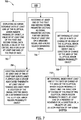
- FIG. 4 is a schematic diagram of an exemplary process 400 for deinterleaving signal parameter vector 138 data that may be used with signal processing system 100 shown in FIG. 3 .
- at least one array data structure 401 is stored at at least one address in memory 134 (not shown).
- Array data structure 401 includes a plurality of arrays including a sparse (e.g., coarse) array (e.g., grid denoted "Level 1") 402, a medium array 404 ("Level 2"), and a fine array 406 ("Level 3").
- Each array of the plurality of arrays includes a plurality of elements (e.g., grid coordinates) 407 which are subaddressed from the address of array data structure 401 in memory 134.
- Sparse array 402 contains a lesser number of elements 407 than medium array 404, and fine array 406 contains a greater number of elements 407 than medium array 404. Further, elements 407 of sparse array 402, medium array 404, and fine array 406 represent successively finer representations of substantially equal sized subregions of a physical spatial domain (e.g., at least one of surveillable area 30 and surveillable space 44). At any given time, a collection of elements 407 represents, at any point in time, at least one of an area and a volumetric space of surveillable area 30 and surveillable space 44, respectively.
- the collection of elements 407 represents, over successive points (e.g., frames) in time, a varying, rather than substantially constant, area and volumetric space of surveillable area 30 and surveillable space 44, respectively.
- a shadow hash key routine 408 is stored as software instructions in memory 134 and is executed by computing device 132 (not shown) in a computer-based method. Shadow hash key routine 408 is run on computing device 132 upon a user-initiated start state 410 including, without limitation, at least one of powering on and waking up signal processing system 100. Start state 410 proceeds to a first subroutine 412 during which computing device 132 continually checks whether or not at least one of signal parameter vector 138 data and unknown signal state space representation signal 139 data is received by post-processor 105 from pre-processor 104. If at least one of signal parameter vector 138 data and unknown signal state space representation signal 139 data is not received by post-processor 105, shadow hash key routine 408 loops back and performs first subroutine 412 again.
- shadow hash key routine 408 proceeds to a second subroutine 414.
- computing device 132 executes software instructions to at least one of read (e.g., get), insert (e.g., write), and delete spatially-defined data obtained using sensor 103.
- H 1 k Level 1 hash
- H1(k) is a hash function for mapping keys to elements 407 in sparse array 402
- k is the subaddress of at least one spatially-defined data record in sparse array 402 (e.g., element 407 in sparse array 402 at which the at least one spatially-defined data record is stored in memory 134).
- Key k therefore, corresponds to the subregion of the surveilled physical spatial domain at a given point in time.
- sparse array 402 representative of a two-dimensional surveillable area 30
- k1 is the key
- c1 is a constant (e.g., determined by computing device 132)
- x1 and yl define the index into sparse array 402 having the subaddress of the respective element 407 (e.g., corresponding to a latitude and a longitude in the physical spatial domain).
- shadow hash key routine 408 is executed in conjunction with storing at least one of signal parameter vector 138 data and unknown signal state space representation signal 139 data in memory 134 at a respective element 407 in sparse array 402 corresponding to a subregion in the physical spatial domain.
- computing device 132 determines whether or not the spatially-defined data of interest is present in sparse array 402. If the spatially-defined data of interest is not stored in sparse array 402, computing device 132 then determines whether a pointer to an address in medium array 404 is present and, if so, second subroutine 414 is directed there. In the event the spatially-defined data is not stored in medium array 404, but rather medium array 404 contains a pointer to an address in fine array 406, second subroutine 414 is similarly directed there. Second subroutine 414 continues in this manner until computing device 132 finds the desired data value or values of interest, or it is determined that the value or values are not stored in memory 134.
- a plurality of elements 407 of array data structure 401 will have stored in them a plurality of signal data blocks with associated spatially-defined data values.
- the associated spatially-defined data values are derived from, and represent spatial characteristics of at least one signal emitter 2 physical spatial environment (e.g., at least one surveillable area 30 and surveillable space 44).
- Computing device 132 also executes shadow hash key routine 408 to generate and store in memory 134 at least one elliptical error region probability object 416 representative of spatial information having widely varying error magnitudes and stored in a plurality of elements 407 in more than one of sparse array 402, medium array 404, and fine array 406.
- process 400 includes a first elliptical error region probability object 418 and a second elliptical error region probability object 420.
- Shadow hash key routine 408 also facilitates combining spatial data values including, without limitation, non-sparse spatial objects, of varying sparseness amongst at least two of sparse array 402, medium array 404, and fine array 406 into at least one elliptical error region probability object 416 that is operable on by computing device 132 within a stochastic sparse tree grid including array data structure 401.
- Background examples may be found in U.S. Patent 8,805,858 , titled "Methods and systems for spatial filtering using a stochastic sparse tree grid.” Therefore, elliptical error region probability object 416 enables representation of spatial data initially acquired and further derived from at least one sensor 103 in a single and memory- and computationally-efficient representation.
- shadow hash key routine 408 thus provides an efficient lookup method using shadow hash keys, and it operates within array data structure 401 using individual elements 407 and elliptical error region probability object 416 to store, organize, select, and analyze spatial signal data of interest and to read, write, and delete that data in an operationally-, computationally-, and memory-efficient manner.
- process 400 and shadow hash key routine 408 facilitate use of signal denoising module 118 and the at least one blind source separation module 120 (referred to above as an "EW front-end" of signal processing system 100, not shown).
- process 400 and shadow hash key routine 408 facilitate sharing of spatial information between cooperating sensor 103-containing surveillance platforms (e.g., including at least one of one or more aerial surveillance platforms 6 and/or one or more ground-based surveillance platforms 34) configured to share their information, and employing widely varying types of sensors 103 types, sensors 103 requiring fusion of results, and/or any other sensor 103 front-end that produces sensor data with widely differing error magnitudes for the sensor-derived spatial information produced.
- the addition of process 400 and shadow hash key routine 408 to the methods and systems for spatial filtering using a stochastic sparse tree grid described in U.S. Patent 8,805,858 , supra, enables shadow hash keys to look up ellipsoidal regions in addition to typical grid elements 407 for the purpose of getting, inserting and deleting spatially-defined sensor information in stochastic tree grids.
- ellipsoidal regions including, without limitation, elliptical error region probability objects 416 are meant in a general sense and include intersections of ellipsoidal regions as well as angular regions defined by intersections of half plane regions, for example.
- a half plane can be considered a degenerate ellipse for algorithmic purposes and, therefore, ellipsoidal regions and their intersections refer to generalized ellipsoidal regions and their intersections.
- Widely different error magnitudes in the spatial information from at least one sensor 103 means these different regions are of both very large size and very small size, such that processing them together with standard grids (e.g., fine array 406, which is only efficiently processed with computing device 132 in cases of sparse spatial data within small areas or regions of surveilled physical spatial environment) requires new efficient methodologies.
- standard grids e.g., fine array 406, which is only efficiently processed with computing device 132 in cases of sparse spatial data within small areas or regions of surveilled physical spatial environment
- Process 400 and shadow hash key routine 408 enables this joint processing to be done efficiently and accurately based on a gridding methodology that can include objects such as ellipsoids and half spaces of up to M dimensions, where M is the number of vector input parameters present in signal parameter vector 138 (for example), or of two dimensions in the case of typical electro-optic/infrared-type sensors 103, or of three dimensions in the case of certain Laser/Light Detection and Ranging (LADAR/LIDAR)-based surveillance platform systems.
- LADAR/LIDAR Laser/Light Detection and Ranging
- Sensor fusion involving communicatively cooperating multiple types of sensors 103 includes a plurality of different possible processing dimensions.
- the vector size of the input for the tree grid used in process 400 is denoted below as M, assuming that the vector of inputs are considered as random variables and have associated standard deviations.
- Process 400 thus facilitates an improved method to store and lookup efficiently both sparse grid elements 407 and non-sparse elliptical error region probability objects 416, all within a stochastic tree grid as disclosed previously in U.S. Patent 8,805,858 , supra.
- computing device 132 uses the above described representation of ellipsoid E( ⁇ ,Q) in a projective form for efficiency in computation and memory usage.
- E ⁇ Q x ⁇ Rn
- Q' is an enlarged shape matrix.
- PDF probability density function
- an exemplary use case of process 400 employs at least one elliptical error region probability object 416 with shadow hash key routine 408 on spatially-defined data derived from at least one sensor 103.
- a trimmed normal (e.g., Gaussian) PDF of an error directly corresponds to an ellipsoid.
- the ellipsoidal shape directly maps to the PDF that has this shape as its support.
- the intersection of two half planes represents a wedge that corresponds to a two dimensional angular area out to infinity, which, in an exemplary example, further represents an angle-only sensor 103 provided AOA spatial information.
- a distance along a center line parameterizes a one dimensional (1D) Gaussian PDF with an increasing width.
- an angular region is thus determined defined out to a maximum distance for at least one sensor 103 a known maximum sensitivity and/or surveilling physical spatial environments of interest of a predefined maximum size.
- the intersection of four half planes in three-dimensional (3D) space with each pair orthogonal to the other pair allows a rectangular wedge representing an angle in space out to infinity and distance along center line is parameterized to a two-dimensional (2D) Gaussian PDF with axes given by the orthogonal pairs.
- EW systems e.g., embodied in signal processing system 100 employed for radar pulse sensing, for example
- PWs pulse descriptor words
- Process 400 and shadow hash key routine 408 including, without limitation, utilized in combination with methods and systems for stochastic sparse tree grid for spatial filtering as described in U.S.
- Patent 8,805,858 supra, enable spatial filtering of such EW signals with higher probability of detection of weak signals within spatially defined noise and interfering signals, a higher probability of correct classification through improved statistical methods applied to spatial information.
- Process 400 and shadow hash key routine 408 thus facilitate longer range detection and classification, detection and classification with a smaller antenna 28 and/or aperture, and detection and classification using lower transmit power.
- process 400 and shadow hash key routine 408 facilitates the aforementioned benefits in the context of a single EW platform which can only produce angle of arrival spatial information, rather than a more exact spatial location.
- a single EW platform which can only produce angle of arrival spatial information, rather than a more exact spatial location.
- computational and memory usage efficiency suffers greatly with sparsely classified and organized AOA determinations stored in array data structure 401 in grids with very small elements 407 (e.g., as fine or finer as fine array 406). This is especially true when employing the systems and methods described in U.S.
- Patent 8,805,858 supra, with sparse AOA data and where the sparse stochastic histogram tree grid uses a (multidimensional) sparse stochastic histogram. This is due, in part, to the fact that most bins of fine array 406 have no data when observing ground or airborne signal emitters 2. Similarly, using a single grid to store all signal information to form a spatial filter is inefficient since most spatial information is very irregular.
- array data structure 401 For example, some levels of array data structure 401 are dense and some regions thereof are very sparse, causing a hash table much inefficiency since there it operates under an assumption that the number of keys within a single hash is relatively constant across the entire array, thereby increasing the linear search time to unacceptably high levels as more data values and/or objects are added to array data structure 401.
- Process 400 and shadow has key routine thus improves computation and memory usage efficiency to record occupancy of the plurality of histograms by reducing the number of grid elements 407 needed overall in array data structure 401 by creating sparsity through multiple levels (e.g., at least two of sparse array 402, medium array 404, and fine array 406) of the tree grid.
- Shadow hash key routine 408 to this multi-level and multi-resolution grid approach improves performance of spatial filtering further by enabling computing device 132 to perform get, insert and delete operations not only on individual array levels of array data structure 401, but on at least one elliptical error region probability object 416 as well.
- process 400 with shadow hash key routine 408 uses stochastic histograms in place of ordinary histograms having discrete bins into which data either falls within or does not, resulting in a distortion of the appearance of the histogram depending on the bin size and whether the data lands in the center of the bin or near an edge thereof.
- the ordinary histogram approaches a binned PDF of the data as more and more data is added, provided the bin size is small enough.
- the aforementioned distortion causes the histogram to approach the PDF much more slowly than the stochastic histogram approach and, hence, requires more data (which is often scarce in practice) and more memory to get good results.
- the stochastic histogram approach employed by process 400 and shadow hash key routine 408 uses the measured or assumed variance of each parameter to spread the histogram when each data point is added. Thus, instead of only incrementing the bin where a data point falls, nearby bins are added to as well depending on the probability spread. In the case of at least one elliptical error region probability object 416, the spreading is assumed when the PDF is set for each data input and, therefore, this spreading is implied directly. Further, when computing the final value of a grid or location, the values of intersections of at least one elliptical error region probability object 416 values that intersect elements 407 of that grid must be added together.
- a multidimensional sparse stochastic histogram is used in the situation where most bins have no data (e.g., the input data is sparse within the tree grid). It uses the mechanism of the sparse tree grid previously described in its implementation to reduce the memory requirements (e.g., only non-zero bins and elliptical error region probability objects 416 take storage). Again, as with the stochastic histogram, even though the Gaussian distribution has an infinitely long tail, in a practical implementation, a threshold such as plus or minus 3 standard deviations can be used. This limits the number of operations to update a sparse stochastic histogram to a constant times the number of input signals.
- incorporating a priori information is also possible using the newly available elliptical error region probability objects 416.
- a weighting function on the ellipsoid can be computed that is proportional to the probability this a priori information is present given assumed land feature information.
- circular sparse stochastic histograms are used to insert circular measurements (such as used for angle input) and can be associated with an intersection of two half planes (e.g., in two dimensions) and its attendant PDF. It is done by inserting modulo 2 ⁇ or modulo 360°.
- sparse aging using time weighting proceeds on elliptical error region probability objects 416 as with grid elements 407 in the same manner. In particular, it allows the new elliptical error region probability objects 416 to age out and disappear.
- Patent 8,805,858 standard histograms age objects by deleting ones which make up the histogram and which are older than a certain predetermined age (e.g., objects with a time value whose difference with the present time is greater than a predetermined amount).
- a certain predetermined age e.g., objects with a time value whose difference with the present time is greater than a predetermined amount.
- a stochastic histogram keeps linked lists of objects belonging to each "bin" (e.g., grid element 407) in time order and deaccumulates these repetitive signals gradually by using a series of time weights based on a set of time interval ages.
- the weighting could be exponentially decreasing if desired, or even uniform in other cases, depending on particular application requirements of signal processing system 100. Therefore, with process 400 and shadow hash key routine 408, we simply add that the list of objects now include elliptical error region probability objects 416 that age out and disappear over time.
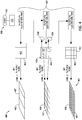
- FIG. 5 is a schematic diagram of first elliptical error region probability object 418 and second elliptical error region probability object 420 determined using process 400 and stored in array data structure 401, as shown in FIG. 4 .
- a does not equal b in medium array 404.
- at least one of sparse array 402 and medium array 404 is embodied in a three-dimensional (e.g., cubic) array. Sparse array 402 and medium array 404 share an origin 502 defined by an address in memory 134.
- a first signal data block 504 of a first type (e.g., a first AOA, denoted by a solid square) received by sensor 103 and deinterleaved by signal processing system 100 at a first time point from a first signal emitter 2 (not shown) maps to sparse array 402.
- a second signal data block 506 of a second type (e.g., a second AOA, denoted by a solid diamond in FIG. 5 ) received from a second signal emitter 2 maps to a first subaddress 508 in medium array 404.
- a third signal data block 510 of a third type (e.g., a first location, denoted by a solid triangle in FIG. 5 ) received from first signal emitter 2 maps to a second subaddress 512.
- first elliptical error region probability object 418 of specific resolved addresses (e.g., locations in the physical spatial domain) of first signal data block 504 with respect to third signal data block 510. Determination of first elliptical error region probability object 418 by computing device 132 includes determining a first center 514 (denoted as a solid dot in FIG.
- First center 514 is representative of a highest probability location at the third point in time of first signal emitter 2 in surveillable area 30, and first pair of axes is representative of the spatial error (e.g., standard deviation) of first center 514 at the third point in time.
- At least one of first elliptical error region probability object 418, first center 514, first pair of axes, and spatial error of first center 514 are at least one of stored in memory 134 and displayed as human-readable data on display 144.
- a fourth signal data block 516 of the first type maps to a third subaddress 518 of medium array 404.
- medium array 404 containing two spatially-defined signal data blocks from second signal emitter 2 after the fourth point in time
- key is found by shadow hash key routine 408, and computing device 132 determines second elliptical error region probability object 420 of specific resolved addresses (e.g., locations in the physical spatial domain) of second signal data block 506 with respect to fourth signal data block 516.
- Determination of second elliptical error region probability object 420 by computing device 132 includes determining a second center 520 (denoted as a solid dot in FIG. 5 ) and a second pair of axes (not shown) of a second ellipsoid region defining second elliptical error region probability object 420 in array data structure 401.
- Second center 520 is representative of a highest probability location of second signal emitter 2 at the fourth point in time in surveillable area 30, and second pair of axes is representative of the spatial error (e.g., standard deviation) of second center 520 at the fourth point in time.
- At least one of second elliptical error region probability object 420, second center 520, second pair of axes, and spatial error of second center 520 are at least one of stored in memory 134 and displayed as human-readable data on display 144.
- a fifth signal data block 522 of the first type (denoted by a solid square in FIG. 5 ) and a first non-standard data point 524 (e.g., not signal parameter vector derived, but rather derived from non-standard data from which spatially defined information is derivable from unknown signal state space representation signal 139), respectively, are received from first signal emitter 2.
- First non-standard data point 524 is denoted by an asterisk in FIG. 5 .
- Fifth signal data block 522 maps to second subaddress 512 and first non-standard data point 524 maps to a fourth subaddress 526.
- first elliptical error region probability object 528 of specific resolved addresses (e.g., locations in the physical spatial domain) of first signal data block 504, third signal data block 510, fifth signal data block 522, and first non-standard data point 524 with respect to one another.
- Determination of refined first elliptical error region probability object 528 by computing device 132 includes determining a refined first center 530 (denoted as an "x" in FIG.
- refined first center 530 is representative of an updated highest probability location of first signal emitter 2 at the sixth point in time in surveillable area 30, and refined first pair of axes is representative of an updated spatial error (e.g., standard deviation) of refined first center 530 at the sixth point in time.
- At least one of refined first elliptical error region probability object 528, refined first center 530, refined first pair of axes, and updated spatial error of refined first center 530 are at least one of stored in memory 134 and displayed as human-readable data on display 144.
- a second non-standard data point 532 (denoted by an asterisk in FIG. 5 ) is received from second signal emitter 2 and maps to third subaddress 518.
- medium array 404 together containing two spatially-defined signal data blocks and one non-standard data point from second signal emitter 2 after seventh point in time, key is found by shadow hash key routine 408, and computing devices determines a refined (e.g., updated) second elliptical error region probability object 534 of specific resolved addresses (e.g., locations in the physical spatial domain) of second signal data block 506, fourth signal data block 516, and second non-standard data point 532 with respect to one another.
- a refined (e.g., updated) second elliptical error region probability object 534 of specific resolved addresses e.g., locations in the physical spatial domain
- Determination of refined second elliptical error region probability object 534 by computing device 132 includes determining a refined second center 536 (denoted as an "x" in FIG. 5 ) and a refined second pair of axes (not shown) of a refined second ellipsoid region defining refined second elliptical error region probability object 534 in array data structure 401.
- Refined second center 536 is representative of an updated highest probability location of second signal emitter 2 at seventh point in time in surveillable area 30, and refined second pair of axes is representative of an updated spatial error (e.g., standard deviation) of refined second center 536 at the seventh point in time.
- At least one of refined second elliptical error region probability object 534, refined second center 536, refined second pair of axes, and updated spatial error of refined second center 536 are at least one of stored in memory 134 and displayed as human-readable data on display 144.
- first data cluster 538 and a second data cluster 540 reside in sparse array 402 and medium array 404.
- refinement of first elliptical error region probability object 418 to refined first elliptical error region probability object 528 increased the respective spatial error and increased the area of the respective ellipsoid region.
- the increase in area of the respective ellipsoid region is indicative of first signal emitter 2 being a mobile signal emitter 2.
- Computing device 132 is also configured to determine at least one of a velocity, an acceleration, and a direction of movement of a mobile signal emitter 2, and at least one of store this data in memory 134 and display it in human-readable form on display 144. In second data cluster 540, however, the respective spatial error and ellipsoid region area decreased, which is indicative that second signal emitter 2 is not mobile.
- Computing device 132 is further configured to delete at least one of outlier signal data blocks and outlier non-standard data points from memory 134 using outlier statistical methods performed from software instructions stored on and executed from memory 134. Such outlier statistical methods facilitate efficient use of memory resources and prevent a mischaracterization of a particular signal emitter 2 as mobile when, in fact, it is stationary in the physical spatial domain.
- computing device 132 when a particular signal emitter 2 has been located in the physical spatial domain with an acceptable error and determined to be stationary, computing device 132 is configured to delete associated data from array data structure 401, thereby freeing space in memory 134.
- signal processing system 100 continues to deinterleave received signals as described above and further refine associated elliptical error region probability objects 416 until such time that an acceptable degree of spatial error is reached and/or a particular signal emitter 2 is determined to be mobile.
- FIG. 6 is a flowchart of an exemplary method 600 of spatially filtering signal parameter vector data that may be used with signal processing system 100 shown in FIG. 3 .
- method 600 includes receiving 602, at computing device 132, a first signal parameter vector (e.g., containing first signal data block 504) at a first time and a second signal parameter vector (e.g., containing third signal data block 510) at a second time occurring after the first time.
- the first and second signal data blocks contain spatially-defined information for signal emitter 2.
- Method 600 also includes transmitting 604, to array data structure 401 stored in memory 134 and having plurality of elements 407 including at least a first element 407 and a second element 407, first signal data block and second signal data block to first and second elements 407, respectively, of array data structure 401 (e.g., elements 407 of at least one of sparse array 402, medium array 404, and fine array 406).
- array data structure 401 is representative of a physical spatial domain (e.g., surveillable area 30) from which the plurality of signals are received by, for example, sensor 103, from signal emitter 2.
- Method 600 further includes determining 606, with computing device 132, elliptical error region probability object 416 containing first and second signal data blocks and having a center (e.g., first center 514) and a pair of axes. Center is representative of a highest probability location of signal emitter 2 in physical spatial domain at the second time, and pair of axes is representative of a spatial error of center at the second time. Determining also includes storing elliptical error region probability object 416 in memory 134 in association with array data structure 401.
- FIG. 7 is a flowchart of an alternative method 700 of spatially filtering signal parameter vector data that may be used with signal processing system 100 shown in FIG. 3 .
- method 700 includes steps of method 600 as shown and described above with reference to FIG. 6 .
- Method 700 also includes displaying 702 data output signal 142 as human-readable data via display 144 coupled to computing device 132, at least one of elliptical probability error region object (e.g., at least one of elliptical error probability region objects 418 and 420), a value of at least one of first 504 and second 506 signal data blocks, a value of center (e.g., at least one of centers 514 and 520), and a value of at least one axis of the pair of axes.
- elliptical probability error region object e.g., at least one of elliptical error probability region objects 418 and 420
- center e.g., at least one of centers 514 and 520
- Method 700 further includes directing 704 movement of at least one of the at least one surveillance platform (e.g., at least one of surveillance platforms 6 and 34) and device associated therewith (e.g., at least one of devices 31 and 42) at least one of toward and away from a location of signal emitter (e.g., at least one of signal emitters 2, 8, 10, 36, and 38) based on a determination of the elliptical error region probability object.
- the at least one surveillance platform e.g., at least one of surveillance platforms 6 and 34
- device associated therewith e.g., at least one of devices 31 and 42
- signal emitter e.g., at least one of signal emitters 2, 8, 10, 36, and 38
- receiving 602 further includes receiving 706 at least one of the first and second signal parameter vectors 138 as signal parameter vectors 138 further derived from at least one of denoised signal 124 and blind source separated signal 129.
- Method 700 also includes determining 708, with computing device 132, at least one of a rate of change of an area of elliptical error region probability object and a direction of change of the area of elliptical error region probability object.
- Method 700 further includes determining 710, with computing device 132 and based on at least one of the rate of change of the area of elliptical error region probability object and the direction of change of the area of elliptical error region probability object, at least one of: a presence of movement of signal emitter, a direction of movement of signal emitter, a velocity of signal emitter, and an acceleration of signal emitter.
- FIG. 8 is a flowchart of an alternative method 800 of spatially filtering signal parameter vector data that may be used with signal processing system 100 shown in FIG. 3 .
- method 800 includes steps of method 600, as shown and described above with reference to FIG. 6 .
- array data structure 401 includes a plurality of arrays (e.g., sparse array 402, medium array 404, and fine array 406).
- the plurality of arrays includes a first array having a first number of elements 407 and a second array having a second number of elements 407.
- transmitting 604 (as shown and described above with reference to FIG.
- determining 606 (as shown and described above with reference to FIG. 6 ) further includes assigning 802, with computing device 132, at least one of the first 504 and second 506 signal data blocks to one of the first and second arrays. Furthermore, in an alternative example, in method 800, determining 606 (as shown and described above with reference to FIG.
- determining 804 the elliptical error region probability object e.g., first elliptical error region probability object 418 and/or second elliptical error region probability object 420
- determining 804 the elliptical error region probability object e.g., first elliptical error region probability object 418 and/or second elliptical error region probability object 420
- FIG. 9 is a flowchart of an alternative method 900 of spatially filtering signal parameter vector data that may be used with signal processing system 100 shown in FIG. 3 .
- method 900 includes steps of method 600, as shown and described above with reference to FIG. 6 .
- Method 900 also includes receiving 902, at computing device 132 at least one of before, after, and substantially simultaneously with the second time, at least one unknown signal state space representation signal 139 derived from a denoised signal 124 pulse of at least one signal of the plurality of signals 18 and 20 and including at least one non-standard spatially-defined data point (e.g., at least one of non-standard spatially-defined data points 524 and 532).
- Method 900 further includes transmitting 904, to at least one element 407 of the plurality of elements 407 in array data structure 401, the at least one non-standard spatially-defined data point.
- determining 606 further includes at least one of: determining 906 the elliptical error region probability object containing the non-standard spatially-defined data point and first signal data block 504; determining 908 the elliptical error region probability object containing the non-standard spatially-defined data point and second signal data block 506; and determining 910 the elliptical error region probability object containing the non-standard spatially-defined data point and the first 504 and second 506 signal data blocks.
- Method also includes determining 912, using shadow hash key routine 408 executed by computing device 132, a presence among the plurality of elements 407 of a matching element 407 containing at least two of first signal data block 504 , second signal data block 506, and the at least one non-standard spatially-defined data point. Also, in determining 912, array data structure 401 is configured as a hash table for shadow hash key routine 408.
- FIG. 10 is a flowchart of an alternative method 1000 of spatially filtering signal parameter vector data that may be used with signal processing system 100 shown in FIG. 3 .
- method 1000 includes steps of method 600, as shown and described above with reference to FIG. 6 .
- Method 1000 also includes determining 1002, using shadow hash key routine 408 executed by computing device 132, a presence among the plurality of elements 407 of a matching element 407 containing first signal data block 504 and second signal data block 506. Also, in determining 1002, array data structure 401 is configured as a hash table for shadow hash key routine 408.
- Method 1000 further includes receiving 1004, at computing device 132, at least one additional signal parameter vector 138 including at least a third signal data block 510 at an (at least one) additional time occurring at least one of after and substantially simultaneously with the second time.
- Method 1000 also includes transmitting 1006, from computing device 132, the third signal data block 510 to a third element 407 in array data structure 401.
- Method 1000 further includes determining 1008, using shadow hash key routine 408, a presence among the plurality of elements 407 of a matching element 407 containing the third signal data block 510 and at least one of first signal data block 504 and second signal data block 506.
- Method 1000 also includes updating 1010, with computing device 132, the elliptical error region probability object (e.g., first elliptical error region probability object 418 and/or second elliptical error region probability object 420) to contain the third signal data block 510 and at least one of first signal data block 504 and second signal data block 506.
- the elliptical error region probability object e.g., first elliptical error region probability object 418 and/or second elliptical error region probability object 420
- the above-described systems and methods for adding functional grid elements to stochastic sparse tree grids for spatial filtering enable efficient and high performance deinterleaving of signal parameter vector data generated using improved pre-processing front-end architectures and methods such as denoising and blind source separation.
- the above-described examples also facilitate high performance deinterleaving of signal parameter vectors containing new characteristics such as additional information.
- the above-described examples further enable efficient generation of useful deinterleaving information of signal parameter vectors during post-processing without requiring highly sophisticated, complex, and expensive processor architectures.
- the above-described systems and methods for adding functional grid elements to stochastic sparse tree grids for spatial filtering also facilitate high performance post-processing of both standard and new signal parameter vector data using a single platform employing a standard processor.
- the above-described examples further provide implementation in a single platform architecture which produces only AOA spatial information, rather than a more exact spatial location.
- the above-described systems and methods for adding functional grid elements to stochastic sparse tree grids for spatial filtering also facilitate combining non-standard signal parameters having widely varying accuracies and employing moving signal emitter spatial signal parameters as part of deinterleaving.
- the above-described examples also enable use of AOA-containing signal parameter vector data to generate accurate results from stochastic histogram methods using standard processors in less time relative to known spatial filtering systems and methods.
- An exemplary technical effect of the above-described systems and methods for adding functional grid elements to stochastic sparse tree grids for spatial filtering includes at least one of the following: (a) enabling efficient and high performance deinterleaving of signal parameter vector data generated using improved pre-processing front-end architectures and methods such as denoising and blind source separation; (b) facilitating high performance deinterleaving of signal parameter vectors containing new characteristics such as additional information; (c) enabling efficient generation of useful deinterleaving information of signal parameter vectors during post-processing without requiring highly sophisticated, complex, and expensive processor architectures; (d) facilitating high performance post-processing of both standard and new signal parameter vector data using a single platform employing a standard processor; (e) providing implementation in a single platform architecture able to provide only AOA spatial information, rather than more exact spatial information; (f) facilitating combining non-standard signal parameters having widely varying accuracies and employing moving signal emitter platform spatial signal parameters as part of deinterleaving; and (g)
- Such devices typically include a processor, processing device, or controller, such as a general purpose central processing unit (CPU), a graphics processing unit (GPU), a microcontroller, a reduced instruction set computer (RISC) processor, an application specific integrated circuit (ASIC), a programmable logic circuit (PLC), a field programmable gate array (FPGA), a digital signal processing (DSP) device, and/or any other circuit or processing device capable of executing the functions described herein.
- the methods described herein may be encoded as executable instructions embodied in a computer-readable medium, including, without limitation, a storage device and/or a memory device. Such instructions, when executed by a processing device, cause the processing device to perform at least a portion of the methods described herein.
- the above examples are exemplary only, and thus are not intended to limit in any way the definition and/or meaning of the term processor and processing device.
Description
- The field of the disclosure relates generally to spatial filtering of signal data received by wide-area surveillance sensors, and, more specifically, to systems and methods for adding functional grid elements to stochastic sparse tree grids for spatial filtering.
- In known spatial filtering systems and methods, improved pre-processing front-end architectures generate signal data vectors having new characteristics and require more extensive processing systems and methods. Improvements in known spatial filtering systems and methods including denoising and blind source separation generate signal parameter vectors containing new characteristics and additional new information types. In order to efficiently generate useful deinterleaving information of signal parameter vectors during post-processing, such known spatial filtering systems and methods require substantially more complex processor architectures. Even with improved post-processing architectures, such known spatial filtering systems and methods suffer from diminished deinterleaving performance with new types of signal parameter vector data and non-standard data relative to standard signal parameter vectors.
- At least some known spatial filtering and signal parameter vector deinterleaving systems and methods are challenging to implement in a single platform architecture which can only produce angle of arrival (AOA) spatial information, rather than a more exact spatial location. Further, at least some known spatial filtering and signal parameter vector deinterleaving systems and methods are unable, absent highly sophisticated, complex, and expensive post-processing computing requirements, to combine non-standard signal parameters having widely varying accuracies and employ moving emitter platform spatial signal parameters as part of signal parameter vector deinterleaving. Finally, when stochastic histogram methods are used to spread out spatial data in a grid with very small cells for the purpose of generating accurate results, in at least some known spatial filtering systems and methods, use of a standard post-processing architecture is unacceptably inefficient.
-
US8805858 , according to its abstract, relates to a computer-based method for processing data. The method includes receiving, at a processing device, data to be processed, processing the data to assign spatial information to the data, the spatial information defining an element on a grid, determining, with the processing device, a sparseness of the processed data through application of the processed data to a multiple resolution level sparse tree filter, placing the processed data within a histogram based on the determined sparseness, and filtering the data based on spatial statistics using a sparse histogram method..EP2988148 , according to its abstract, relates to a bistatic radar system that may include a transmitter, a target at a first known position, a receiver at a second known position, and a transmitter position determination unit. The receiver is configured to receive one or more reflected radar signals transmitted from the transmitter and reflected off the target. The receiver is configured to receive one or more direct radar signals transmitted from the transmitter. The transmitter position determination unit is configured to determine a position of the transmitter based on a determination of a distance between the first and second known positions and a determination of a first angular difference between the reflected radar signal(s) and the direct radar signal(s) that are received by the receiver.US2003/095716 , according to its abstract, relates to a method of spatially filtering a digital image that includes receiving a source digital image including pixels corresponding to one or more different colors; selecting a pixel of interest in the source digital image; calculating two or more noise free pixel estimates for the pixel of interest using pixel values sampled in a local region about the pixel of interest; selecting a final noise free pixel estimate for the pixel of interest from the noise free pixel estimates; and repeating for other pixels in the source digital image to provide a spatially filtered digital image.US5999129 according to its abstract relates to a method and system for determining the geolocation i.e., the latitude, longitude, and altitude-of a stationary RF signal emitter from two or more moving observer aircraft. The observers receive signals from the emitter and the system measures the phase difference between the signals. The observers then perform pulse time of arrival (TOA) measurements over a predetermined clock interval and calculate the time difference of arrival (TDOA) of corresponding, same-pulse, emitter signals. Based on geometric relationships, the system creates a series of circular lines of position (LOPs) for each observer, and computes hyperbolic LOPs based on the TDOA calculations. The system determines emitter location from the intersection of the hyperbolic LOPs and the circular LOPs.US2010/309055 , according to its abstract, relates to systems and methods for passive location of transmitters in which two or more receivers time stamp received signals from target transmitters and the time stamped data for each target signal of interest is isolated to identify a peak power time of arrival for the signal at each transmitter from which differential scan observation values are derived. For each signal of interest a line of position curve is computed based on the differential scan observation value and corresponding receiver locations, and for each signal of interest an estimated target transmitter location is determined based on an intersection of two corresponding line of position curves.US6285319 , according to its abstract, relates to the geolocation of an emitter, using at least one observer measuring signal change while moving on at least two observation tracks. The measurement of emitter signal change is begun between a first observer position and a second observer position. The second observer position is predicted at the time the last measurement from which signal change will be derived is made. The method utilizes knowledge of the measurement start and end points to determine a second pair of observer signal-change measurement start and end positions such that the emitter line-of-position (LOP) determined by the second signal change measurement will intersect the LOP associated with the first signal change measurement at possibly multiple points, but at each of these point intercept orthogonally to within the signal change measurement errors. The method determines the intersection points of the LOPs and assigns a likelihood to each intersection point for measuring the probability for each of the multiple intersection points that it is the emitter location, determines a correct emitter position from these likelihood weights, and generates an error associated with the emitter position estimate. - In one aspect, a method of spatially filtering signal parameter vector data according to claim 5 is provided.
- In another aspect, a system for spatially filtering signal parameter vector data according to
claim 1 is provided. - In yet another aspect, there is provided a non-transient computer-readable memory having computer-executable instructions embodied thereon wherein, when executed by a computing device, the computer-executable instructions cause the computing device to perform all of the steps of the method of claim 5.
- These and other features, aspects, and advantages of the present disclosure will become better understood when the following detailed description is read with reference to the
accompanying drawings in which like characters represent like parts throughout the drawings, wherein: -
FIG. 1 is a schematic diagram of an exemplary physical environment having a plurality of signal emitters residing on a two-dimensional ground surface surveilled by an aerial wide-area sensor surveillance platform. -
FIG. 2 is a schematic diagram of an alternative physical environment having a plurality of signal emitters residing in a three-dimensional sky region surveilled by a ground-based wide-area sensor surveillance platform. -
FIG. 3 is a schematic diagram of an exemplary signal processing system that may be used with the surveillance platforms shown inFIGS. 1 and2 . -
FIG. 4 is a schematic diagram of an exemplary process for deinterleaving signal parameter vector data that may be used with the signal processing system shown inFIG. 3 . -
FIG. 5 is a schematic diagram of a plurality of elliptical error region probability objects stored in an array data structure as determined using the process shown inFIG. 4 . -
FIG. 6 is a flowchart of an exemplary method of spatially filtering signal parameter vector data that may be used with the signal processing system shown inFIG. 3 . -
FIG. 7 is a flowchart of an alternative method of spatially filtering signal parameter vector data that may be used with the signal processing system shown inFIG. 3 . -
FIG. 8 is a flowchart of an alternative method of spatially filtering signal parameter vector data that may be used with the signal processing system shown inFIG. 3 but that is not covered by the scope of the claims. -
FIG. 9 is a flowchart of an alternative method of spatially filtering signal parameter vector data that may be used with the signal processing system shown inFIG. 3 but that is not covered by the scope of the claims. -
FIG. 10 is a flowchart of an alternative method of spatially filtering signal parameter vector data that may be used with the signal processing system shown inFIG. 3 but that is not covered by the scope of the claims. - Unless otherwise indicated, the drawings provided herein are meant to illustrate features of examples of this disclosure. These features are believed to be applicable in a wide variety of systems comprising one or more examples of this disclosure. As such, the drawings are not meant to include all conventional features known by those of ordinary skill in the art to be required for the practice of the examples disclosed herein.
- In the following specification and the claims, reference will be made to a number of terms, which shall be defined to have the following meanings.
- The singular forms "a", "an", and "the" include plural references unless the context clearly dictates otherwise.
- "Optional" or "optionally" means that the subsequently described event or circumstance may or may not occur, and that the description includes instances where the event occurs and instances where it does not.
- Approximating language, as used herein throughout the specification and claims, may be applied to modify any quantitative representation that could permissibly vary without resulting in a change in the basic function to which it is related. Accordingly, a value modified by a term or terms, such as "about", "approximately", and "substantially", are not to be limited to the precise value specified. In at least some instances, the approximating language may correspond to the precision of an instrument for measuring the value. Here and throughout the specification and claims, range limitations may be combined and/or interchanged, and such ranges are identified and include all the sub-ranges contained therein unless context or language indicates otherwise.
- As used herein, the terms "processor" and "computer" and related terms, e.g., "processing device", "computing device", and "controller" are not limited to just those integrated circuits referred to in the art as a computer, but broadly refers to a microcontroller, a microcomputer, a programmable logic controller (PLC), an application specific integrated circuit (ASIC), and other programmable circuits, and these terms are used interchangeably herein. In the examples described herein, memory may include, but is not limited to, a computer-readable medium, such as a random access memory (RAM), and a computer-readable non-volatile medium, such as flash memory. Alternatively, a floppy disk, a compact disc - read only memory (CD-ROM), a magneto-optical disk (MOD), and/or a digital versatile disc (DVD) may also be used. Also, in the examples described herein, additional input channels may be, but are not limited to, computer peripherals associated with an operator interface such as a mouse and a keyboard. Alternatively, other computer peripherals may also be used that may include, for example, but not be limited to, a scanner. Furthermore, in the exemplary example, additional output channels may include, but not be limited to, an operator interface monitor.
- Also, as used herein, the terms "blind source separate", "blind source separated", and "blind source separation" refer to systems and methods employed for separating (e.g., filtering) one or more source signals of interest from a plurality of mixed signals. In applications including, without limitation, an underdetermined case (e.g., fewer observed signals than signal sources), blind source separation facilitates filtering pure signals of interest from an arbitrary set of time-varying signals (e.g., radar pulses from one or more signal emitters) without relying on substantial amounts of known information about the source signals or the signal mixing process.
- Further, as used herein, the terms "denoise", "denoised", and "denoising" relate to devices, systems and methods employed to improve the quality of and pre-condition signals of interest received from a noisy environment. Denoising received signals of interest facilitates additional signal processing of the received signals of interest using additional devices, systems, and methods downstream from where signals of interest are initially received by a receiving device such as an antenna.
- Furthermore, as used herein, the term "real-time" refers to at least one of the time of occurrence of the associated events, the time of measurement and collection of predetermined data, the time to process the data, and the time of a system response to the events and the environment. In the examples described herein, these activities and events occur substantially instantaneously.
- The systems and methods for adding functional grid elements to stochastic sparse tree grids for spatial filtering described herein enable efficient and high performance deinterleaving of signal parameter vector data generated using improved pre-processing front-end architectures and methods such as denoising and blind source separation. The examples described herein also facilitate high performance deinterleaving of signal parameter vectors containing new characteristics such as additional information. The examples described herein further enable efficient generation of useful deinterleaving information of signal parameter vectors during post-processing without requiring highly sophisticated, complex, and expensive processor architectures. The systems and methods for adding functional grid elements to stochastic sparse tree grids for spatial filtering described herein also facilitate high performance post-processing of both standard and new signal parameter vector data using a single platform employing a standard processor. The examples described herein further provide implementation in a single platform architecture which produces only angle of arrival (AOA) spatial information, rather than a more exact spatial location. The systems and methods for adding functional grid elements to stochastic sparse tree grids for spatial filtering described herein also facilitate combining non-standard signal parameters having widely varying accuracies and employing moving emitter platform spatial signal parameters as part of deinterleaving. The examples described herein also enable use of AOA-containing signal parameter vector data to generate accurate results from stochastic histogram methods using standard processors in less time relative to known spatial filtering systems and methods.
-
FIG. 1 is a schematic diagram of an exemplaryphysical environment 1 having a plurality ofsignal emitters 2 residing on a two-dimensional ground surface 4 surveilled by a wide-area sensor-based aerial surveillance platform 6 including, without limitation, anaircraft 7. In an exemplary example, a first ground-basedsignal emitter 8 is stationary and a second ground-basedsignal emitter 10 is mobile (e.g., through wheels 12). Both of first ground-basedsignal emitter 8 and second ground-basedsignal emitter 10 include atransceiver 14 configured to transmit an electromagnetic signal including, without limitation, a radar signal pulse, into a three-dimensional space including, without limitation, asky 16.Transceiver 14 is also configured to detect aerial surveillance platform 6 through a reflection of at least one of afirst signal 18 and asecond signal 20 from aerial surveillance platform 6. Characteristics of aerial surveillance platform 6 detectable by first ground-basedsignal emitter 8 and second ground-basedsignal emitter 10 include, without limitation, spatial (e.g., locational) information of aerial surveillance platform 6 insky 16 discerned from a first reflectedsignal 22 and a second reflectedsignal 24, respectively, received bytransceiver 14. Spatial information includes, without limitation, a distance (e.g., range) of aerial surveillance platform 6 fromtransceiver 14, an azimuth fromtransceiver 14, an elevation relative totransceiver 14, and a velocity of aerial surveillance platform 6. - Also, in an exemplary example, aerial surveillance platform 6 includes a
signal processing platform 26 including a receivingantenna 28.Antenna 28 is configured to receive at least one offirst signal 18 andsecond signal 20 fromtransceiver 14.Antenna 28 is also configured to transmit at least one offirst signal 18 andsecond signal 20 to signalprocessing platform 26.Antenna 28 andsignal processing platform 26 include analog and digital electronic circuit components (not shown) configured to at least one of detect, process, quantify, store, and display various characteristics offirst signal 18 andsecond signal 20. Characteristics offirst signal 18 andsecond signal 20 include, without limitation, a frequency, a time of arrival, a time of departure, a pulse width, a pulse amplitude, a pulse repetition interval, and an AOA.Signal processing platform 26 also includes an analog-to-digital converter configured to generate at least one signal parameter vector containing at least one of the aforementioned characteristics offirst signal 18 andsecond signal 20 as digital data to be processed using a computer-based method on electronic hardware running software executed from a non-transient computer-readable storage media. - In operation, in an exemplary example,
signal processing platform 26 provides spatial and identification information about eachsignal emitter 2 of the plurality ofsignal emitters 2 located onground surface 4 in asurveillable area 30 ofantenna 28 on aerial surveillance platform 6. Signal data processing methods implemented bysignal processing platform 26 including, without limitation, computer-based methods, generate further data in substantially real-time, facilitating substantially real-time determinations of characteristics of eachsignal emitter 2 of the plurality ofsignal emitters 2. Characteristics ofsignal emitters 2 determined by signal data processing methods implemented bysignal processing platform 26 include, without limitation, an authorization of aparticular signal emitter 2 to operate in thesurveillable area 30, whether aparticular signal emitter 2 is moving or stationary, and a level of threat (e.g., identification, friend or foe - IFF) that aparticular signal emitter 2 poses to at least one of aerial surveillance platform 6,other signal emitters 2 in thesurveillable area 30, and any other persons and property (not shown) in at least one ofsurveillable area 30 andsky 16. - Also, in operation in an exemplary example, characteristics of
signal emitters 2 determined by signal data processing methods implemented bysignal processing platform 26 also cause a variety of substantially real-time physical actions in physical devices and systems in at least one of electrical communication and data communication withsignal processing platform 26. For example, characteristics ofsignal emitters 2 determined by signal data processing methods implemented bysignal processing platform 26 are displayed on at least one of a human machine interface (HMI) and a display, including, without limitation, as a map having a grid representative of a two-dimensional physical spatial domain including the surveillablearea 30, where locations and identities of at least one of first ground-basedsignal emitter 8 and second ground-basedsignal emitter 10 are plotted substantially in real-time at their respective grid coordinates. Also, for example, characteristics ofsignal emitters 2 determined by signal data processing methods implemented bysignal processing platform 26 are transmitted in substantially real-time as data to actuator controllers in aerial surveillance platform 6 (e.g., rudders and flaps of aircraft 7) to facilitate evasive maneuvers thereof (e.g., by an autopilot function ofaircraft 7, including whereaircraft 7 is a drone) to avoid an area of operation of aparticular signal emitter 2 determined to be a threat. - As a further example, characteristics of
signal emitters 2 determined by signal data processing methods implemented bysignal processing platform 26 are transmitted in substantially real-time as data as a warning signal to aparticular signal emitter 2 operating in thesurveillable area 30 without authorization. In addition to the warning signal, characteristics ofsignal emitters 2 determined by signal data processing methods implemented bysignal processing platform 26 are transmitted in substantially real-time as data as an alert signal to an associatedmobile device 31 operating in the vicinity of a particular unauthorized and/orthreatening signal emitter 2. For example, alert signal is transmitted to at least one of a police and a military unit, including at least one of a robotic and autonomous unit (e.g., drone) having actuator controllers enabled to receive the data and actuate directed movement toward the particular unauthorized and/or threatening signal emitter 2 (e.g., to neutralize the particular unauthorized and/or threatening signal emitter 2). Also, for example, characteristics ofsignal emitters 2 determined by signal data processing methods implemented bysignal processing platform 26 are transmitted in substantially real-time as data as a control signal to at least one of an electronic support measure (ESM) and an electronic warfare (EW) system positioned at least one ofproximate antenna 28 and distal aerial surveillance platform 6 to direct, for example, a jamming signal (not shown) at aparticular signal emitter 2 operating in thesurveillable area 30 without authorization. -
FIG. 2 is a schematic diagram of an alternativephysical environment 32 having a plurality ofsignal emitters 2 residing in a three-dimensional airspace 33 surveilled by a ground-based wide-areasensor surveillance platform 34 including, without limitation, a mobile surveillance platform (e.g., having wheels 12). In an alternative example, a firstaerial signal emitter 36 is coupled toaircraft 7 and a secondaerial signal emitter 38 is embodied in adrone 40. Both of firstaerial signal emitter 36 and secondaerial signal emitter 38 includetransceiver 14 configured to transmit a signal to at least one ofairspace 33 andground surface 4.Transceiver 14 is also configured to detect ground-basedsurveillance platform 34, an associated ground-baseddevice 42, as well as other aerial objects (not shown) through a reflection of at least one offirst signal 18 andsecond signal 20, as shown and described above with reference toFIG. 1 . Characteristics of ground-basedsurveillance platform 34 detectable by firstaerial signal emitter 36 and secondaerial signal emitter 38 include, without limitation, spatial information of ground-basedsurveillance platform 34 onground surface 4 discerned from a first reflectedsignal 22 and a second reflectedsignal 24, respectively, received bytransceiver 14. Spatial information includes, without limitation, a distance (e.g., range) of ground-basedsurveillance platform 34 fromtransceiver 14, an azimuth fromtransceiver 14, an elevation relative totransceiver 14, and a velocity of ground-based surveillance platform 34 (e.g., where ground-basedsurveillance platform 34 is mobile). - Also, in an alternative example, ground-based
surveillance platform 34 includessignal processing platform 26 includingantenna 28 configured to receive at least one offirst signal 18 andsecond signal 20 fromtransceiver 14.Antenna 28 is also configured to transmit at least one offirst signal 18 andsecond signal 20 to signalprocessing platform 26.Antenna 28 andsignal processing platform 26 include analog and digital electronic circuit components (not shown) configured to at least one of detect, process, quantify, store, and display various characteristics offirst signal 18 andsecond signal 20. Characteristics offirst signal 18 andsecond signal 20 include, without limitation, frequency, time of arrival, time of departure, pulse width, pulse amplitude, pulse repetition interval, and AOA.Signal processing platform 26 also includes an analog-to-digital converter configured to generate at least one signal parameter vector containing at least one of the aforementioned characteristics offirst signal 18 andsecond signal 20 as digital data to be processed using a computer-based method on electronic hardware running software executed from a non-transient computer-readable storage media. - In operation, in an alternative example,
signal processing platform 26 provides spatial and identification information about eachsignal emitter 2 of the plurality ofsignal emitters 2 located inairspace 33 in a surveillable space 44 (e.g., sky 16) ofantenna 28 on ground-basedsurveillance platform 34. In other examples, not shown,surveillable space 44 is a surveillable volume of water (e.g. under the surface of a body of water). In still other examples, not shown,surveillable space 44 is a surveillable region of outer space. Signal data processing methods implemented bysignal processing platform 26 including, without limitation, computer-based methods, generate further data in substantially real-time, facilitating substantially real-time determinations of characteristics of eachsignal emitter 2 of the plurality ofsignal emitters 2. Characteristics ofsignal emitters 2 determined by signal data processing methods implemented bysignal processing platform 26 include, without limitation, an authorization of aparticular signal emitter 2 to operate in thesurveillable space 44, whether aparticular signal emitter 2 is traveling at a supersonic velocity of not, and a level of threat that aparticular signal emitter 2 poses to at least one of ground-basedsurveillance platform 34,other signal emitters 2 in thesurveillable space 44 ofairspace 33, and any other persons and property (not shown) in at least one of thesurveillable space 44 and theentire airspace 33. - Also, in operation in an alternative example, characteristics of
signal emitters 2 determined by signal data processing methods implemented bysignal processing platform 26 also cause a variety of substantially real-time physical actions in physical devices and systems in at least one of electrical communication and data communication withsignal processing platform 26. For example, characteristics ofsignal emitters 2 determined by signal data processing methods implemented bysignal processing platform 26 are displayed on at least one of an HMI and a display, including, without limitation, as a map having a grid representative of a three-dimensional physical spatial domain including thesurveillable space 44, where locations and identities of at least one of firstaerial signal emitter 36 and secondaerial signal emitter 38 are plotted substantially in real-time at their respective grid coordinates. Also, for example, characteristics ofsignal emitters 2 determined by signal data processing methods implemented bysignal processing platform 26 are transmitted in substantially real-time as data to actuator controllers in mobile examples of at least one of ground-basedsurveillance platform 34 and associated ground-based device 42 (e.g., steering and drive train of a vehicle) to facilitate evasive maneuvers thereof (e.g., by at least one of manual, autonomous, and robotic functionality) to avoid an area of operation onground surface 4 of aparticular signal emitter 2 determined to be a threat. - As a further example, characteristics of
signal emitters 2 determined by signal data processing methods implemented bysignal processing platform 26 are transmitted in substantially real-time as data as a warning signal to aparticular signal emitter 2 operating in thesurveillable space 44 without authorization. In addition to the warning signal, characteristics ofsignal emitters 2 determined by signal data processing methods implemented bysignal processing platform 26 are transmitted in substantially real-time as data as an alert signal to associated ground-baseddevice 42 operating in the vicinity of a particular unauthorized and/orthreatening signal emitter 2. For example, alert signal is transmitted to at least one of a police and military unit, including at least one of a robotic and autonomous unit (e.g., drone) having actuator controllers enabled to receive the data and actuate directed movement toward the particular unauthorized and/or threatening signal emitter 2 (e.g., to neutralize the particular unauthorized and/or threatening signal emitter 2). Also, for example, characteristics ofsignal emitters 2 determined by signal data processing methods implemented bysignal processing platform 26 are transmitted in substantially real-time as data as a control signal to at least one of an ESM and an EW system positioned at least one ofproximate antenna 28 and distal ground-basedsurveillance platform 34 to direct, for example, a jamming signal (not shown) at aparticular signal emitter 2 operating in thesurveillable space 44 without authorization. -
FIG. 3 is a schematic diagram of an exemplarysignal processing system 100 that may be used with the surveillance platforms (e.g., aerial surveillance platform 6 and/or ground-based surveillance platform 34) shown inFIGS. 1 and2 , respectively. In an exemplary implementation,signal processing system 100 generates pulse descriptor word (PDW)vectors 138 using blind source separation (BSS) of received signals derived from, for example, and without limitation, radar signals. More generally, in other implementations,signal processing system 100 enables generating signal parameter vectors (e.g., a signal parameter vector 138) other than PDW vectors in a substantially similar manner as described herein. Also known as blind signal separation, BSS is used to separate (e.g., filter) one or more source signals of interest from a plurality of mixed signals. In applications including, without limitation, an underdetermined case (e.g., fewer observed signals than signal sources), BSS facilitates separating and identifying pure signals of interest from an arbitrary set of time-varying signals (e.g., radar pulses from one or more signal emitters) without relying on substantial amounts of known information about the signal emitters, signals of interest, or the signal mixing process. - In the exemplary example,
signal processing system 100 includes asignal data processor 101 communicatively coupled toantenna 28.Antenna 28, in the exemplary example, is a wide-area sensor 103.Signal data processor 101 includes a pre-processor 104 and a post-processor 105.Sensor 103 is configured to receive signals from, for example, and without limitation, first and secondaerial signal emitters signal emitters FIG. 3 , those of skill in the art will appreciate thatsensor 103 may receive signals from any number ofsignal emitters -
Sensor 103 is communicatively coupled topre-processor 104 through a pre-conditioner 108. In the exemplary example, pre-conditioner 108 includes alow noise amplifier 109, aband pass filter 110, and a wideband analog-to-digital converter (ADC) 111. In operation, pre-conditioner 108 is configured to convert asensor output signal 112 received fromsensor 103 into anincoming signal 113 transmitted topre-processor 104. Eachincoming signal 113 is derived from a time-varying signal received atsensor 103. Time-varying signal may include a mix of signals received fromsignal emitters first signal 18 andsecond signal 20. - In the exemplary example,
pre-processor 104 includes one or moresignal denoising modules 118, and a plurality of blind source separation (BSS)modules 120. EachBSS module 120 is coupled to a singlesignal denoising module 118, and represents oneBSS channel 200. A total number ofBSS channels 200 insignal processing system 100 is expressed as K.Signal denoising module 118 transmits adenoised signal 124 and astate energy signal 126 to each respective BSS module 120 (e.g., 120a, 120b, ... , 120K) of the plurality ofBSS modules 120.State energy signal 126 represents a quantity (e.g., an analog voltage level) that is proportional to an amplitude ofincoming signal 113 at particular sampled time points (e.g., states). - In operation,
incoming signal 113 is transmitted frompre-conditioner 108 to signaldenoising module 118 whereincoming signal 113 undergoes signal denoising and is subsequently transmitted asdenoised signal 124 to the eachBSS module 120. For example,first signal 18 is initially received atsensor 103 as a pulse having signal characteristics including, without limitation, a frequency and a bandwidth. In this example, a single pulse offirst signal 18, after processing bypre-conditioner 108, is then received atsignal denoising module 118 as a mixed signal (e.g., theincoming signal 113 represents a signal pulse of thefirst signal 18 and has various characteristics including, without limitation, noise and information other than the desired information of interest).Signal denoising module 118 denoises the mixedincoming signal 113 prior to transmittingdenoised signal 124 having a frequency and a bandwidth (or a regular pattern of frequencies and bandwidths) to theBSS modules 120. Methods implemented bysignal processing system 100 are performed in substantially real-time by the devices and systems described above. - Further, in the exemplary example,
pre-processor 104 includes one or morePDW generation modules 128 coupled to eachBSS module 120, and apulse denoising module 130 coupled to eachBSS module 120.PDW generation module 128 generatesPDW parameter vector 138 based on blind source separated signals 129 received from eachBSS module 120. EachPDW parameter vector 138 contains data representative of characteristics of interest of one ofsignals Pulse denoising module 130 also generates an unknown signal statespace representation signal 139 based on blind source separated signals 129. Unknown signal statespace representation signal 139 contains data representative of additional (e.g., non-PDW-type) characteristics of interest of one ofsignals signal emitters PDW parameter vectors 138 and unknown signal state space representation signals 139 are transmitted topost-processor 105.Signal denoising module 118,PDW generation module 128, andpulse denoising module 130 include suitable signal filtering, signal amplification, signal modulation, signal separation, signal conditioning, and/or ADC circuitry implemented using analog and/or digital electronic circuit components. Also, in the exemplary example, eachBSS module 120 transmits a respective blind source separated signal 129 (e.g., 129a, 129b, ... , 129K) toPDW generation module 128 and topulse denoising module 130. -
Post-processor 105 includes acomputing device 132 that includes amemory 134. As described above,PDW generation module 128 receives blind source separated signals 129 from eachrespective BSS module 120.PDW generation module 128 then utilizes the blind source separated signals 129 to generate aPDW parameter vector 138, which is subsequently transmitted topost-processor 105.PDW parameter vector 138 is received by computingdevice 132 and stored as non-transient computer-readable data inmemory 134 including, without limitation, as at least one buffered data set.Pulse denoising module 130 is also configured to receive blind source separated signals 129 from eachrespective BSS module 120.Pulse denoising module 130 is further configured to utilize the blind source separated signals 129 to generate the unknown signal statespace representation signal 139, which is subsequently transmitted topost-processor 105. Unknown signal statespace representation signal 139 is received by computingdevice 132 and stored as non-transient computer-readable data inmemory 134 including, without limitation, as at least one buffered data set. In the exemplary example,computing device 132 fetches buffered data sets frommemory 134 for processing using a computer-based method employing an operating system running software executed from instruction set data also stored in a non-transient memory 134 (e.g., from one or more non-transient computer-readable storage media). -
Computing device 132 implements a computer-based method (e.g., from software instructions stored in memory 134) to carry out operations based on data contained in at least one ofPDW parameter vector 138 and unknown signal statespace representation signal 139. Such operations include, without limitation, detecting, processing, quantifying, storing, and displaying (e.g., in human readable data form) various characteristics of at least one signal (e.g., signals 18 and 20) represented as data in at least one ofPDW parameter vector 138 and unknown signal statespace representation signal 139. For example,PDW parameter vector 138 generated byPDW generation module 128 contains a plurality of PDW vector data blocks structured in a vector form, where each PDW vector data block contains one parameter offirst signal 18. Parameters (e.g., representative of at least one characteristic of first signal 18) include, without limitation, frequency, bandwidth, time of arrival, time of departure, pulse width, pulse amplitude, pulse repetition interval, and/or AOA.Computing device 132 readsPDW parameter vector 138 and carries out at least one of the aforementioned operations on at least one PDW vector data block of the plurality of PDW vector data blocks. Also, in the exemplary example,computing device 132 reads and separates (e.g., deinterleaves)PDW parameter vector 138 into its constituent PDW vector data blocks, and stores fewer PDW vector data blocks inmemory 134 than the total number of PDW vector data blocks contained inPDW parameter vector 138. Deinterleaving ofPDW parameter vector 138 enables determining characteristics of interest ofsignals 18 and/or 20 by computingdevice 132 to, for example, and without limitation, accurately determine and track spatial information forsignal emitters 36 and/or 38. In other implementations,computing device 132 reads and separates all PDW vector data blocks from one another and stores all data contained therein inmemory 134.Computing device 132 performs the aforementioned operations substantially simultaneously (e.g., in real-time) upon receipt ofsignals sensor 103. - Resultant data from operations performed by computing
device 132 are stored inmemory 134. Further, in the exemplary example,computing device 132 causes post-processor 105 to transmit adata output signal 142 to an HMI to facilitate at least one of an interaction, a modification, a visualization, at least one further operation, and a viewable recording of information aboutsignals signal processing system 100. HMI is, for example, adisplay 144 which receivesdata output signal 142 frompost-processor 105. In one example, characteristics (e.g., location characteristics such as grid coordinates in a physical spatial domain, e.g., two-dimensional ground surface 4) representing a physical location ofsignal emitters signal processing system 100, are displayed ondisplay 144, and are updated in substantially in real time.Data output signal 142 is also transmitted from post-processor 105 to at least one device and/or system (e.g., a vehicle 146) associated withsignal processing system 100. Further,computing device 132 enables post-processor 105 to transmit, in substantially real-time, anactuator control signal 148 to anactuator controller 150 included withinvehicle 146 to facilitate controllingvehicle 146. For example,vehicle 146 may be a remotely and/or autonomously operated land vehicle and/or an unmanned aerial vehicle (UAV, e.g., drone 40). - In one mode of operation, at least one of frequency and bandwidth information contained in respective
PDW parameter vectors 138 is displayed ondisplay 144 along with locations ofrespective signal emitters particular signal emitters signal emitter display 144 is automatically updated in substantially real-time to show the location information of at least one respectivemobile signal emitter computing device 132 also determines at least one of a velocity, an acceleration, a trajectory, and a track (e.g., including present and prior locations) of the at least one respectivemobile signal emitter signal data processor 101 also trigger a variety of substantially real time physical actions in physical devices and systems in communication withsignal processing system 100. For example, characteristics ofsignal emitters signal processing system 100, are transmitted in substantially real-time as data toactuator controller 150 in vehicle 146 (e.g., to control rudders and flaps of a UAV). Ifsignal emitters actuator controller 150maneuvers vehicle 146 to avoid an area of operation ofsignal emitters signal emitters signal emitters signal processing system 100 to direct, for example, a jamming signal atsignal emitters sensor 103 without authorization. - In operation, each
BSS module 120 of the plurality ofBSS modules 120 insignal processing system 100 implements filtering methods with dynamic updating to enable generating high quality PDWs containing at least one of frequency, center frequency, bandwidth, pulse time, and pulse width information. Such improved accuracy and resolution of PDWs to track, for example, frequency and bandwidth of signals of interest facilitates identifying, determining, and/or analyzingsignal emitters signal emitters display 144 after being transmitted thereto by post-processor 105 asdata output signal 142, as described above. This improved information enablessignal processing system 100 to distinguish firstaerial signal emitter 36 from secondaerial signal emitter 38. Also, for example,different signal emitters sensor 103 are plotted at respective locations (e.g., grid coordinates) on display 144 (e.g., as a map). - Also, in operation, the plurality of
BSS modules 120 separate a plurality ofdenoised signals 124. EachBSS module 120 contains a plurality of tunable filters (not shown), where each filter operates based on filter parameters including, without limitation, a center frequency and a bandwidth. Further, in the exemplary example,pre-processor 104 includes aBSS control module 196, which facilitates controlling eachrespective BSS module 120 of the plurality ofBSS modules 120.BSS control module 196 receives respective BSS data signals 197 (e.g., 197a, 197b, ... , 197K) containing BSS-related information including, without limitation, frequency, bandwidth, and state, from eachBSS module 120 of the plurality ofBSS modules 120. Based on the BSS-related information contained in BSS data signals 197,BSS control module 196 also generates and transmits respective BSS control signals 198 (e.g., 198a, 198b, .. ., 198K) back to eachrespective BSS module 120 to control, for example and without limitation, a timing of receipt ofdenoised signal 124 and transmission of respective blind source separated signals 129 to at least one ofPDW generation module 128 andpulse denoising module 130. Information contained in BSS data signals 197 and BSS control signals 198 is used byBSS control module 196 to facilitate implementation of a feedback control loop. -
FIG. 4 is a schematic diagram of anexemplary process 400 for deinterleavingsignal parameter vector 138 data that may be used withsignal processing system 100 shown inFIG. 3 . In an exemplary example, at least onearray data structure 401 is stored at at least one address in memory 134 (not shown).Array data structure 401 includes a plurality of arrays including a sparse (e.g., coarse) array (e.g., grid denoted "Level 1") 402, a medium array 404 ("Level 2"), and a fine array 406 ("Level 3"). Each array of the plurality of arrays includes a plurality of elements (e.g., grid coordinates) 407 which are subaddressed from the address ofarray data structure 401 inmemory 134.Sparse array 402 contains a lesser number ofelements 407 thanmedium array 404, andfine array 406 contains a greater number ofelements 407 thanmedium array 404. Further,elements 407 ofsparse array 402,medium array 404, andfine array 406 represent successively finer representations of substantially equal sized subregions of a physical spatial domain (e.g., at least one ofsurveillable area 30 and surveillable space 44). At any given time, a collection ofelements 407 represents, at any point in time, at least one of an area and a volumetric space ofsurveillable area 30 andsurveillable space 44, respectively. In the case of a mobile signal data processing platform 26 (not shown) havingsignal processing system 100, the collection ofelements 407 represents, over successive points (e.g., frames) in time, a varying, rather than substantially constant, area and volumetric space ofsurveillable area 30 andsurveillable space 44, respectively. - Also, in an exemplary example, a shadow hash
key routine 408 is stored as software instructions inmemory 134 and is executed by computing device 132 (not shown) in a computer-based method. Shadow hashkey routine 408 is run oncomputing device 132 upon a user-initiatedstart state 410 including, without limitation, at least one of powering on and waking upsignal processing system 100. Startstate 410 proceeds to afirst subroutine 412 during whichcomputing device 132 continually checks whether or not at least one ofsignal parameter vector 138 data and unknown signal statespace representation signal 139 data is received by post-processor 105 frompre-processor 104. If at least one ofsignal parameter vector 138 data and unknown signal statespace representation signal 139 data is not received bypost-processor 105, shadow hash key routine 408 loops back and performsfirst subroutine 412 again. - If, during
first subroutine 412,computing device 132 determines that at least one ofsignal parameter vector 138 data and unknown signal statespace representation signal 139 data is received by post-processor 105 frompre-processor 104, shadow hash key routine 408 proceeds to asecond subroutine 414. Duringsecond subroutine 414,computing device 132, in conjunction withmemory 134, executes software instructions to at least one of read (e.g., get), insert (e.g., write), and delete spatially-defined data obtained usingsensor 103. Also, duringsecond subroutine 414 executes a first shadow hash key function defined as:
elements 407 insparse array 402, and k is the subaddress of at least one spatially-defined data record in sparse array 402 (e.g.,element 407 insparse array 402 at which the at least one spatially-defined data record is stored in memory 134). Key k, therefore, corresponds to the subregion of the surveilled physical spatial domain at a given point in time. In the case ofsparse array 402 representative of a two-dimensional surveillablearea 30, key k is determined as follows:
sparse array 402 having the subaddress of the respective element 407 (e.g., corresponding to a latitude and a longitude in the physical spatial domain). - Further, in an exemplary example, shadow hash
key routine 408 is executed in conjunction with storing at least one ofsignal parameter vector 138 data and unknown signal statespace representation signal 139 data inmemory 134 at arespective element 407 insparse array 402 corresponding to a subregion in the physical spatial domain. Duringsecond subroutine 414,computing device 132 checks whether or not a key k1 is found by H1(k) hash function. If key k1 is not found,computing device 132 executes a second shadow hash key function, H2(k) =Level 2 hash, substantially similar to the first shadow hash key function, but performed onmedium array 404 rather thansparse array 402. If key k1 is found,computing device 132 determines whether or not the spatially-defined data of interest is present insparse array 402. If the spatially-defined data of interest is not stored insparse array 402,computing device 132 then determines whether a pointer to an address inmedium array 404 is present and, if so,second subroutine 414 is directed there. In the event the spatially-defined data is not stored inmedium array 404, but rathermedium array 404 contains a pointer to an address infine array 406,second subroutine 414 is similarly directed there.Second subroutine 414 continues in this manner until computingdevice 132 finds the desired data value or values of interest, or it is determined that the value or values are not stored inmemory 134. - As further shown and described below with reference to
FIGS. 5-6 , with each successive signal received, vectorized, and deinterleaved bysignal processing system 100 over time, a plurality ofelements 407 ofarray data structure 401 will have stored in them a plurality of signal data blocks with associated spatially-defined data values. The associated spatially-defined data values are derived from, and represent spatial characteristics of at least onesignal emitter 2 physical spatial environment (e.g., at least onesurveillable area 30 and surveillable space 44).Computing device 132 also executes shadow hash key routine 408 to generate and store inmemory 134 at least one elliptical errorregion probability object 416 representative of spatial information having widely varying error magnitudes and stored in a plurality ofelements 407 in more than one ofsparse array 402,medium array 404, andfine array 406. In an exemplary example,process 400 includes a first elliptical errorregion probability object 418 and a second elliptical errorregion probability object 420. Shadow hashkey routine 408 also facilitates combining spatial data values including, without limitation, non-sparse spatial objects, of varying sparseness amongst at least two ofsparse array 402,medium array 404, andfine array 406 into at least one elliptical errorregion probability object 416 that is operable on by computingdevice 132 within a stochastic sparse tree grid includingarray data structure 401. Background examples may be found inU.S. Patent 8,805,858 , titled "Methods and systems for spatial filtering using a stochastic sparse tree grid." Therefore, elliptical errorregion probability object 416 enables representation of spatial data initially acquired and further derived from at least onesensor 103 in a single and memory- and computationally-efficient representation. Further, in an exemplary example, shadow hash key routine 408 thus provides an efficient lookup method using shadow hash keys, and it operates withinarray data structure 401 usingindividual elements 407 and elliptical errorregion probability object 416 to store, organize, select, and analyze spatial signal data of interest and to read, write, and delete that data in an operationally-, computationally-, and memory-efficient manner. - In the context of
U.S. Patent 8,805,858 , supra,process 400 and shadow hash key routine 408 facilitate use ofsignal denoising module 118 and the at least one blind source separation module 120 (referred to above as an "EW front-end" ofsignal processing system 100, not shown). Also, in other examples, not shown,process 400 and shadow hash key routine 408 facilitate sharing of spatial information between cooperating sensor 103-containing surveillance platforms (e.g., including at least one of one or more aerial surveillance platforms 6 and/or one or more ground-based surveillance platforms 34) configured to share their information, and employing widely varying types ofsensors 103 types,sensors 103 requiring fusion of results, and/or anyother sensor 103 front-end that produces sensor data with widely differing error magnitudes for the sensor-derived spatial information produced. The addition ofprocess 400 and shadow hash key routine 408 to the methods and systems for spatial filtering using a stochastic sparse tree grid described inU.S. Patent 8,805,858 , supra, enables shadow hash keys to look up ellipsoidal regions in addition totypical grid elements 407 for the purpose of getting, inserting and deleting spatially-defined sensor information in stochastic tree grids. - In operation, in an exemplary example, ellipsoidal regions including, without limitation, elliptical error region probability objects 416 are meant in a general sense and include intersections of ellipsoidal regions as well as angular regions defined by intersections of half plane regions, for example. A half plane can be considered a degenerate ellipse for algorithmic purposes and, therefore, ellipsoidal regions and their intersections refer to generalized ellipsoidal regions and their intersections. Widely different error magnitudes in the spatial information from at least one
sensor 103 means these different regions are of both very large size and very small size, such that processing them together with standard grids (e.g.,fine array 406, which is only efficiently processed withcomputing device 132 in cases of sparse spatial data within small areas or regions of surveilled physical spatial environment) requires new efficient methodologies.Process 400 and shadow hashkey routine 408 enables this joint processing to be done efficiently and accurately based on a gridding methodology that can include objects such as ellipsoids and half spaces of up to M dimensions, where M is the number of vector input parameters present in signal parameter vector 138 (for example), or of two dimensions in the case of typical electro-optic/infrared-type sensors 103, or of three dimensions in the case of certain Laser/Light Detection and Ranging (LADAR/LIDAR)-based surveillance platform systems. - Sensor fusion involving communicatively cooperating multiple types of
sensors 103, in an exemplary example, includes a plurality of different possible processing dimensions. In general, however, the vector size of the input for the tree grid used inprocess 400 is denoted below as M, assuming that the vector of inputs are considered as random variables and have associated standard deviations. When the tree grid ofprocess 400 and shadow hashkey routine 408 is used in this manner with implied or measured errors in an entire set of parameters, the regions can become so large as to be computationally- and memory-inefficient if implemented using sparse techniques described inU.S. Patent 8,805,858 , supra.Process 400 thus facilitates an improved method to store and lookup efficiently bothsparse grid elements 407 and non-sparse elliptical error region probability objects 416, all within a stochastic tree grid as disclosed previously inU.S. Patent 8,805,858 , supra. Basic objects being added to the stochastic tree grid inprocess 400 are defined as follows:
An ellipsoid E(µ,Q) in Rn with center mu (µ) and shape matrix Q is the set:
- Also, in operation,
computing device 132 uses the above described representation of ellipsoid E(µ,Q) in a projective form for efficiency in computation and memory usage. Thus, (M+2)(M+1) unique coefficients for a general ellipsoid of dimension M is defined by:

- Further, in operation, an exemplary use case of
process 400 employs at least one elliptical errorregion probability object 416 with shadow hashkey routine 408 on spatially-defined data derived from at least onesensor 103. By operating at a 3-sigma (3σ) level for example, the support of a trimmed normal (e.g., Gaussian) PDF of an error directly corresponds to an ellipsoid. Hence, the ellipsoidal shape directly maps to the PDF that has this shape as its support. The intersection of two half planes represents a wedge that corresponds to a two dimensional angular area out to infinity, which, in an exemplary example, further represents an angle-onlysensor 103 provided AOA spatial information. A distance along a center line parameterizes a one dimensional (1D) Gaussian PDF with an increasing width. By combining this with an intersection of a circle of a given radius (a special type of ellipse), an angular region is thus determined defined out to a maximum distance for at least one sensor 103 a known maximum sensitivity and/or surveilling physical spatial environments of interest of a predefined maximum size. The intersection of four half planes in three-dimensional (3D) space with each pair orthogonal to the other pair allows a rectangular wedge representing an angle in space out to infinity and distance along center line is parameterized to a two-dimensional (2D) Gaussian PDF with axes given by the orthogonal pairs. - EW systems (e.g., embodied in
signal processing system 100 employed for radar pulse sensing, for example) are receive-only systems that have front-end receivers that produce, for example, and without limitation, pulse descriptor words (PDWs) for each radar pulse they detect. They are unlike radar systems in that they do not naturally produce range and they must handle unknown signals rather than detect reflected versions of their transmitted signals. Also, since there is more than one type of EW signal that must be detected, the detection is more than one dimensional.Process 400 and shadow hash key routine 408 including, without limitation, utilized in combination with methods and systems for stochastic sparse tree grid for spatial filtering as described inU.S. Patent 8,805,858 , supra, enable spatial filtering of such EW signals with higher probability of detection of weak signals within spatially defined noise and interfering signals, a higher probability of correct classification through improved statistical methods applied to spatial information.Process 400 and shadow hash key routine 408 thus facilitate longer range detection and classification, detection and classification with asmaller antenna 28 and/or aperture, and detection and classification using lower transmit power. - Furthermore, in operation,
process 400 and shadow hashkey routine 408 facilitates the aforementioned benefits in the context of a single EW platform which can only produce angle of arrival spatial information, rather than a more exact spatial location. During surveillance of a very large 2D physical area or 3D physical space where at least onesignal emitter 2 of interest might be located, computational and memory usage efficiency suffers greatly with sparsely classified and organized AOA determinations stored inarray data structure 401 in grids with very small elements 407 (e.g., as fine or finer as fine array 406). This is especially true when employing the systems and methods described inU.S. Patent 8,805,858 , supra, with sparse AOA data and where the sparse stochastic histogram tree grid uses a (multidimensional) sparse stochastic histogram. This is due, in part, to the fact that most bins offine array 406 have no data when observing ground orairborne signal emitters 2. Similarly, using a single grid to store all signal information to form a spatial filter is inefficient since most spatial information is very irregular. For example, some levels ofarray data structure 401 are dense and some regions thereof are very sparse, causing a hash table much inefficiency since there it operates under an assumption that the number of keys within a single hash is relatively constant across the entire array, thereby increasing the linear search time to unacceptably high levels as more data values and/or objects are added toarray data structure 401. - Moreover, in operation, when the only spatial information comes from AOA of
signal emitter 2 pulses from the very large surveilled environment, the associated error is large and therefore the number of occupied histograms will be large when spreading using stochastic techniques.Process 400 and shadow has key routine thus improves computation and memory usage efficiency to record occupancy of the plurality of histograms by reducing the number ofgrid elements 407 needed overall inarray data structure 401 by creating sparsity through multiple levels (e.g., at least two ofsparse array 402,medium array 404, and fine array 406) of the tree grid. Adding shadow hash key routine 408 to this multi-level and multi-resolution grid approach improves performance of spatial filtering further by enablingcomputing device 132 to perform get, insert and delete operations not only on individual array levels ofarray data structure 401, but on at least one elliptical errorregion probability object 416 as well. - Moreover, in operation,
process 400 with shadow hash key routine 408 uses stochastic histograms in place of ordinary histograms having discrete bins into which data either falls within or does not, resulting in a distortion of the appearance of the histogram depending on the bin size and whether the data lands in the center of the bin or near an edge thereof. Mathematically, the ordinary histogram approaches a binned PDF of the data as more and more data is added, provided the bin size is small enough. However, the aforementioned distortion causes the histogram to approach the PDF much more slowly than the stochastic histogram approach and, hence, requires more data (which is often scarce in practice) and more memory to get good results. The stochastic histogram approach employed byprocess 400 and shadow hash key routine 408 uses the measured or assumed variance of each parameter to spread the histogram when each data point is added. Thus, instead of only incrementing the bin where a data point falls, nearby bins are added to as well depending on the probability spread. In the case of at least one elliptical errorregion probability object 416, the spreading is assumed when the PDF is set for each data input and, therefore, this spreading is implied directly. Further, when computing the final value of a grid or location, the values of intersections of at least one elliptical errorregion probability object 416 values that intersectelements 407 of that grid must be added together. - Also, in operation, a multidimensional sparse stochastic histogram is used in the situation where most bins have no data (e.g., the input data is sparse within the tree grid). It uses the mechanism of the sparse tree grid previously described in its implementation to reduce the memory requirements (e.g., only non-zero bins and elliptical error region probability objects 416 take storage). Again, as with the stochastic histogram, even though the Gaussian distribution has an infinitely long tail, in a practical implementation, a threshold such as plus or
minus 3 standard deviations can be used. This limits the number of operations to update a sparse stochastic histogram to a constant times the number of input signals. Also, in operation ofprocess 400, incorporating a priori information is also possible using the newly available elliptical error region probability objects 416. For example, there is often fixed spatial information coming from maps or physical features within space that can influence the spatial filter differently at different locations and this can be captured inarray data structure 401 through bothgrid elements 407 and ellipsoidal. Therefore, a weighting function on the ellipsoid can be computed that is proportional to the probability this a priori information is present given assumed land feature information. - Further, in operation, slight modifications on the aforementioned systems and methods to add to stochastic histograms can proceed as before. For example, circular sparse stochastic histograms are used to insert circular measurements (such as used for angle input) and can be associated with an intersection of two half planes (e.g., in two dimensions) and its attendant PDF. It is done by inserting modulo 2π or modulo 360°. Also, sparse aging using time weighting proceeds on elliptical error region probability objects 416 as with
grid elements 407 in the same manner. In particular, it allows the new elliptical error region probability objects 416 to age out and disappear. Referring back to systems and methods described inU.S. Patent 8,805,858 , supra, standard histograms age objects by deleting ones which make up the histogram and which are older than a certain predetermined age (e.g., objects with a time value whose difference with the present time is greater than a predetermined amount). This allows unclassified objects to "age out" of the histogram. In particular, noise signals would not ordinarily be tracked and so would remain untracked until ultimately disappearing. This is necessary since otherwise the noise floor on a spatial filter histogram would continue to rise until even strongly accumulating bins of repetitive signals would be swamped by adjacent noise bins. In contrast, in operation ofprocess 400, by using time weighting, a stochastic histogram keeps linked lists of objects belonging to each "bin" (e.g., grid element 407) in time order and deaccumulates these repetitive signals gradually by using a series of time weights based on a set of time interval ages. Thus, the weighting could be exponentially decreasing if desired, or even uniform in other cases, depending on particular application requirements ofsignal processing system 100. Therefore, withprocess 400 and shadow hashkey routine 408, we simply add that the list of objects now include elliptical error region probability objects 416 that age out and disappear over time. -
FIG. 5 is a schematic diagram of first elliptical errorregion probability object 418 and second elliptical errorregion probability object 420 determined usingprocess 400 and stored inarray data structure 401, as shown inFIG. 4 . In an exemplary example,sparse array 402 is embodied in a two dimensional (2D) a-by-b array with a=1 and b=1, and having oneelement 407 representative of a subregion ofsurveillable area 30. Overlayed onsparse array 402 ismedium array 404 embodied in a 2D a-by-b array with a=3 and b=3, and having nineelements 407 representative of nine subregions ofsurveillable area 30. In other examples, not shown, a does not equal b inmedium array 404. In still other examples, not shown, at least one ofsparse array 402 andmedium array 404 is embodied in a three-dimensional (e.g., cubic) array.Sparse array 402 andmedium array 404 share anorigin 502 defined by an address inmemory 134. A first signal data block 504 of a first type (e.g., a first AOA, denoted by a solid square) received bysensor 103 and deinterleaved bysignal processing system 100 at a first time point from a first signal emitter 2 (not shown) maps tosparse array 402. At a second point in time after the first point in time, a second signal data block 506 of a second type (e.g., a second AOA, denoted by a solid diamond inFIG. 5 ) received from asecond signal emitter 2 maps to afirst subaddress 508 inmedium array 404. Next, at a third point in time after the second point in time, a third signal data block 510 of a third type (e.g., a first location, denoted by a solid triangle inFIG. 5 ) received fromfirst signal emitter 2 maps to asecond subaddress 512. - With
sparse array 402 andsecond subaddress 512 together containing two spatially-defined signal data blocks fromfirst signal emitter 2 after the third point in time, key is found by shadow hashkey routine 408, andcomputing device 132 determines first elliptical errorregion probability object 418 of specific resolved addresses (e.g., locations in the physical spatial domain) of first signal data block 504 with respect to third signal data block 510. Determination of first elliptical errorregion probability object 418 by computingdevice 132 includes determining a first center 514 (denoted as a solid dot inFIG. 5 ) and a first pair of axes (not shown) of a first ellipsoidal region defining first elliptical errorregion probability object 418 inarray data structure 401.First center 514 is representative of a highest probability location at the third point in time offirst signal emitter 2 insurveillable area 30, and first pair of axes is representative of the spatial error (e.g., standard deviation) offirst center 514 at the third point in time. At least one of first elliptical errorregion probability object 418,first center 514, first pair of axes, and spatial error offirst center 514 are at least one of stored inmemory 134 and displayed as human-readable data ondisplay 144. - At a fourth point in time after the third point in time, a fourth signal data block 516 of the first type (denoted by a solid square in
FIG. 5 ) maps to athird subaddress 518 ofmedium array 404. Withmedium array 404 containing two spatially-defined signal data blocks fromsecond signal emitter 2 after the fourth point in time, key is found by shadow hashkey routine 408, andcomputing device 132 determines second elliptical errorregion probability object 420 of specific resolved addresses (e.g., locations in the physical spatial domain) of second signal data block 506 with respect to fourth signal data block 516. Determination of second elliptical errorregion probability object 420 by computingdevice 132 includes determining a second center 520 (denoted as a solid dot inFIG. 5 ) and a second pair of axes (not shown) of a second ellipsoid region defining second elliptical errorregion probability object 420 inarray data structure 401.Second center 520 is representative of a highest probability location ofsecond signal emitter 2 at the fourth point in time insurveillable area 30, and second pair of axes is representative of the spatial error (e.g., standard deviation) ofsecond center 520 at the fourth point in time. At least one of second elliptical errorregion probability object 420,second center 520, second pair of axes, and spatial error ofsecond center 520 are at least one of stored inmemory 134 and displayed as human-readable data ondisplay 144. - At a fifth time point and a sixth time point, a fifth signal data block 522 of the first type (denoted by a solid square in
FIG. 5 ) and a first non-standard data point 524 (e.g., not signal parameter vector derived, but rather derived from non-standard data from which spatially defined information is derivable from unknown signal state space representation signal 139), respectively, are received fromfirst signal emitter 2. Firstnon-standard data point 524 is denoted by an asterisk inFIG. 5 . Fifth signal data block 522 maps tosecond subaddress 512 and firstnon-standard data point 524 maps to afourth subaddress 526. Withsparse array 402 andmedium array 404 together containing three spatially-defined signal data blocks and one non-standard data point fromfirst signal emitter 2 after sixth point in time, key is found by shadow hashkey routine 408, andcomputing device 132 determines a refined (e.g., updated) first elliptical errorregion probability object 528 of specific resolved addresses (e.g., locations in the physical spatial domain) of first signal data block 504, third signal data block 510, fifth signal data block 522, and firstnon-standard data point 524 with respect to one another. Determination of refined first elliptical errorregion probability object 528 by computingdevice 132 includes determining a refined first center 530 (denoted as an "x" inFIG. 5 ) and a refined first pair of axes (not shown) of a refined first ellipsoid region defining refined first elliptical errorregion probability object 528 inarray data structure 401. Refinedfirst center 530 is representative of an updated highest probability location offirst signal emitter 2 at the sixth point in time insurveillable area 30, and refined first pair of axes is representative of an updated spatial error (e.g., standard deviation) of refinedfirst center 530 at the sixth point in time. At least one of refined first elliptical errorregion probability object 528, refinedfirst center 530, refined first pair of axes, and updated spatial error of refinedfirst center 530 are at least one of stored inmemory 134 and displayed as human-readable data ondisplay 144. - At a seventh time point, a second non-standard data point 532 (denoted by an asterisk in
FIG. 5 ) is received fromsecond signal emitter 2 and maps tothird subaddress 518. Withmedium array 404 together containing two spatially-defined signal data blocks and one non-standard data point fromsecond signal emitter 2 after seventh point in time, key is found by shadow hashkey routine 408, and computing devices determines a refined (e.g., updated) second elliptical errorregion probability object 534 of specific resolved addresses (e.g., locations in the physical spatial domain) of second signal data block 506, fourth signal data block 516, and secondnon-standard data point 532 with respect to one another. Determination of refined second elliptical errorregion probability object 534 by computingdevice 132 includes determining a refined second center 536 (denoted as an "x" inFIG. 5 ) and a refined second pair of axes (not shown) of a refined second ellipsoid region defining refined second elliptical errorregion probability object 534 inarray data structure 401. Refinedsecond center 536 is representative of an updated highest probability location ofsecond signal emitter 2 at seventh point in time insurveillable area 30, and refined second pair of axes is representative of an updated spatial error (e.g., standard deviation) of refinedsecond center 536 at the seventh point in time. At least one of refined second elliptical errorregion probability object 534, refinedsecond center 536, refined second pair of axes, and updated spatial error of refinedsecond center 536 are at least one of stored inmemory 134 and displayed as human-readable data ondisplay 144. - Also, in an exemplary example, after second
non-standard data point 532 is stored inarray data structure 401 and seventh time point has elapsed, afirst data cluster 538 and asecond data cluster 540 reside insparse array 402 andmedium array 404. Forfirst data cluster 538, refinement of first elliptical errorregion probability object 418 to refined first elliptical errorregion probability object 528 increased the respective spatial error and increased the area of the respective ellipsoid region. The increase in area of the respective ellipsoid region is indicative offirst signal emitter 2 being amobile signal emitter 2.Computing device 132 is also configured to determine at least one of a velocity, an acceleration, and a direction of movement of amobile signal emitter 2, and at least one of store this data inmemory 134 and display it in human-readable form ondisplay 144. Insecond data cluster 540, however, the respective spatial error and ellipsoid region area decreased, which is indicative thatsecond signal emitter 2 is not mobile.Computing device 132 is further configured to delete at least one of outlier signal data blocks and outlier non-standard data points frommemory 134 using outlier statistical methods performed from software instructions stored on and executed frommemory 134. Such outlier statistical methods facilitate efficient use of memory resources and prevent a mischaracterization of aparticular signal emitter 2 as mobile when, in fact, it is stationary in the physical spatial domain. - Further, in an exemplary example, when a
particular signal emitter 2 has been located in the physical spatial domain with an acceptable error and determined to be stationary,computing device 132 is configured to delete associated data fromarray data structure 401, thereby freeing space inmemory 134. When aparticular signal emitter 2 has not yet been located in the physical spatial domain with an acceptable error,signal processing system 100 continues to deinterleave received signals as described above and further refine associated elliptical error region probability objects 416 until such time that an acceptable degree of spatial error is reached and/or aparticular signal emitter 2 is determined to be mobile. -
FIG. 6 is a flowchart of anexemplary method 600 of spatially filtering signal parameter vector data that may be used withsignal processing system 100 shown inFIG. 3 . In an exemplary example,method 600 includes receiving 602, atcomputing device 132, a first signal parameter vector (e.g., containing first signal data block 504) at a first time and a second signal parameter vector (e.g., containing third signal data block 510) at a second time occurring after the first time. The first and second signal data blocks contain spatially-defined information forsignal emitter 2.Method 600 also includes transmitting 604, toarray data structure 401 stored inmemory 134 and having plurality ofelements 407 including at least afirst element 407 and asecond element 407, first signal data block and second signal data block to first andsecond elements 407, respectively, of array data structure 401 (e.g.,elements 407 of at least one ofsparse array 402,medium array 404, and fine array 406).Array data structure 401 is representative of a physical spatial domain (e.g., surveillable area 30) from which the plurality of signals are received by, for example,sensor 103, fromsignal emitter 2.Method 600 further includes determining 606, withcomputing device 132, elliptical errorregion probability object 416 containing first and second signal data blocks and having a center (e.g., first center 514) and a pair of axes. Center is representative of a highest probability location ofsignal emitter 2 in physical spatial domain at the second time, and pair of axes is representative of a spatial error of center at the second time. Determining also includes storing elliptical errorregion probability object 416 inmemory 134 in association witharray data structure 401. -
FIG. 7 is a flowchart of analternative method 700 of spatially filtering signal parameter vector data that may be used withsignal processing system 100 shown inFIG. 3 . In an alternative example,method 700 includes steps ofmethod 600 as shown and described above with reference toFIG. 6 .Method 700 also includes displaying 702data output signal 142 as human-readable data viadisplay 144 coupled tocomputing device 132, at least one of elliptical probability error region object (e.g., at least one of elliptical error probability region objects 418 and 420), a value of at least one of first 504 and second 506 signal data blocks, a value of center (e.g., at least one ofcenters 514 and 520), and a value of at least one axis of the pair of axes.Method 700 further includes directing 704 movement of at least one of the at least one surveillance platform (e.g., at least one of surveillance platforms 6 and 34) and device associated therewith (e.g., at least one ofdevices 31 and 42) at least one of toward and away from a location of signal emitter (e.g., at least one ofsignal emitters - Also, in an alternative example, in
method 700, receiving 602 (as shown and described above with reference toFIG. 6 ) further includes receiving 706 at least one of the first and secondsignal parameter vectors 138 assignal parameter vectors 138 further derived from at least one ofdenoised signal 124 and blind source separated signal 129.Method 700 also includes determining 708, withcomputing device 132, at least one of a rate of change of an area of elliptical error region probability object and a direction of change of the area of elliptical error region probability object.Method 700 further includes determining 710, withcomputing device 132 and based on at least one of the rate of change of the area of elliptical error region probability object and the direction of change of the area of elliptical error region probability object, at least one of: a presence of movement of signal emitter, a direction of movement of signal emitter, a velocity of signal emitter, and an acceleration of signal emitter. -
FIG. 8 is a flowchart of analternative method 800 of spatially filtering signal parameter vector data that may be used withsignal processing system 100 shown inFIG. 3 . In an alternative example,method 800 includes steps ofmethod 600, as shown and described above with reference toFIG. 6 . Also, in an alternative example, inmethod 800,array data structure 401 includes a plurality of arrays (e.g.,sparse array 402,medium array 404, and fine array 406). The plurality of arrays includes a first array having a first number ofelements 407 and a second array having a second number ofelements 407. Further, in an alternative example, inmethod 700, transmitting 604 (as shown and described above with reference toFIG. 6 ) further includes assigning 802, withcomputing device 132, at least one of the first 504 and second 506 signal data blocks to one of the first and second arrays. Furthermore, in an alternative example, inmethod 800, determining 606 (as shown and described above with reference toFIG. 6 ) further includes at least one of: determining 804 the elliptical error region probability object (e.g., first elliptical errorregion probability object 418 and/or second elliptical error region probability object 420) containing the first signal data block 504 in the first array and the second signal data block 506 in the first array; determining 806 the elliptical error region probability object containing first signal data block 504 in first array and second signal data block 506 in second array; determining 808 the elliptical error region probability object containing first signal data block 504 in second array and second signal data block 506 in first array; and determining 810 the elliptical error region probability object containing first signal data block 504 in second array and second signal data block 506 in second array. -
FIG. 9 is a flowchart of analternative method 900 of spatially filtering signal parameter vector data that may be used withsignal processing system 100 shown inFIG. 3 . In an alternative example,method 900 includes steps ofmethod 600, as shown and described above with reference toFIG. 6 .Method 900 also includes receiving 902, atcomputing device 132 at least one of before, after, and substantially simultaneously with the second time, at least one unknown signal statespace representation signal 139 derived from adenoised signal 124 pulse of at least one signal of the plurality ofsignals data points 524 and 532).Method 900 further includes transmitting 904, to at least oneelement 407 of the plurality ofelements 407 inarray data structure 401, the at least one non-standard spatially-defined data point. - Also, in an alternative example, in
method 900, determining 606 (as shown and described above with reference toFIG. 6 ) further includes at least one of: determining 906 the elliptical error region probability object containing the non-standard spatially-defined data point and first signal data block 504; determining 908 the elliptical error region probability object containing the non-standard spatially-defined data point and second signal data block 506; and determining 910 the elliptical error region probability object containing the non-standard spatially-defined data point and the first 504 and second 506 signal data blocks. Method also includes determining 912, using shadow hash key routine 408 executed by computingdevice 132, a presence among the plurality ofelements 407 of amatching element 407 containing at least two of first signal data block 504 , second signal data block 506, and the at least one non-standard spatially-defined data point. Also, in determining 912,array data structure 401 is configured as a hash table for shadow hashkey routine 408. -
FIG. 10 is a flowchart of analternative method 1000 of spatially filtering signal parameter vector data that may be used withsignal processing system 100 shown inFIG. 3 . In an alternative example,method 1000 includes steps ofmethod 600, as shown and described above with reference toFIG. 6 .Method 1000 also includes determining 1002, using shadow hash key routine 408 executed by computingdevice 132, a presence among the plurality ofelements 407 of amatching element 407 containing first signal data block 504 and second signal data block 506. Also, in determining 1002,array data structure 401 is configured as a hash table for shadow hashkey routine 408.Method 1000 further includes receiving 1004, atcomputing device 132, at least one additionalsignal parameter vector 138 including at least a third signal data block 510 at an (at least one) additional time occurring at least one of after and substantially simultaneously with the second time. -
Method 1000 also includes transmitting 1006, from computingdevice 132, the third signal data block 510 to athird element 407 inarray data structure 401.Method 1000 further includes determining 1008, using shadow hashkey routine 408, a presence among the plurality ofelements 407 of amatching element 407 containing the third signal data block 510 and at least one of first signal data block 504 and second signal data block 506.Method 1000 also includes updating 1010, withcomputing device 132, the elliptical error region probability object (e.g., first elliptical errorregion probability object 418 and/or second elliptical error region probability object 420) to contain the third signal data block 510 and at least one of first signal data block 504 and second signal data block 506. - The above-described systems and methods for adding functional grid elements to stochastic sparse tree grids for spatial filtering enable efficient and high performance deinterleaving of signal parameter vector data generated using improved pre-processing front-end architectures and methods such as denoising and blind source separation. The above-described examples also facilitate high performance deinterleaving of signal parameter vectors containing new characteristics such as additional information. The above-described examples further enable efficient generation of useful deinterleaving information of signal parameter vectors during post-processing without requiring highly sophisticated, complex, and expensive processor architectures. The above-described systems and methods for adding functional grid elements to stochastic sparse tree grids for spatial filtering also facilitate high performance post-processing of both standard and new signal parameter vector data using a single platform employing a standard processor. The above-described examples further provide implementation in a single platform architecture which produces only AOA spatial information, rather than a more exact spatial location. The above-described systems and methods for adding functional grid elements to stochastic sparse tree grids for spatial filtering also facilitate combining non-standard signal parameters having widely varying accuracies and employing moving signal emitter spatial signal parameters as part of deinterleaving. The above-described examples also enable use of AOA-containing signal parameter vector data to generate accurate results from stochastic histogram methods using standard processors in less time relative to known spatial filtering systems and methods.
- An exemplary technical effect of the above-described systems and methods for adding functional grid elements to stochastic sparse tree grids for spatial filtering includes at least one of the following: (a) enabling efficient and high performance deinterleaving of signal parameter vector data generated using improved pre-processing front-end architectures and methods such as denoising and blind source separation; (b) facilitating high performance deinterleaving of signal parameter vectors containing new characteristics such as additional information; (c) enabling efficient generation of useful deinterleaving information of signal parameter vectors during post-processing without requiring highly sophisticated, complex, and expensive processor architectures; (d) facilitating high performance post-processing of both standard and new signal parameter vector data using a single platform employing a standard processor; (e) providing implementation in a single platform architecture able to provide only AOA spatial information, rather than more exact spatial information; (f) facilitating combining non-standard signal parameters having widely varying accuracies and employing moving signal emitter platform spatial signal parameters as part of deinterleaving; and (g) enabling use of AOA-containing signal parameter vector data to generate accurate results from stochastic histogram methods using standard processors in less time relative to known spatial filtering systems and methods.
- Although specific features of various examples of the disclosure may be shown in some drawings and not in others, this is for convenience only. In accordance with the principles of the disclosure, any feature of a drawing may be referenced and/or claimed in combination with any feature of any other drawing.
- Some examples involve the use of one or more electronic or computing devices. Such devices typically include a processor, processing device, or controller, such as a general purpose central processing unit (CPU), a graphics processing unit (GPU), a microcontroller, a reduced instruction set computer (RISC) processor, an application specific integrated circuit (ASIC), a programmable logic circuit (PLC), a field programmable gate array (FPGA), a digital signal processing (DSP) device, and/or any other circuit or processing device capable of executing the functions described herein. The methods described herein may be encoded as executable instructions embodied in a computer-readable medium, including, without limitation, a storage device and/or a memory device. Such instructions, when executed by a processing device, cause the processing device to perform at least a portion of the methods described herein. The above examples are exemplary only, and thus are not intended to limit in any way the definition and/or meaning of the term processor and processing device.
- This written description uses examples to disclose the examples, including the best mode, and also to enable any person skilled in the art to practice the examples, including making and using any devices or systems and performing any incorporated methods. The patentable scope of the disclosure is defined by the claims.
Claims (12)
- A system (100) for spatially filtering signal parameter vector (138) data generated by at least one surveillance platform (6, 34) from a plurality of signals (18, 20) of a signal emitter (2, 8, 10, 36, 38), said system comprising a signal data processor including a sensor, a pre-processor, and a post-processor, the sensor (103) configured to receive the plurality of signals; the pre-processor configured to generate a plurality of signal parameter vectors derived from the plurality of signals and including a first signal parameter vector and a second signal parameter vector, each signal parameter vector of the plurality of signal parameter vectors derived from one signal of the plurality of signals, wherein the first signal parameter vector includes a first signal data block (504) and the second signal parameter vector includes a second signal data block (506), and wherein the first and the second signal data blocks contain spatially-defined information for the signal emitter; the pre-processor (104) further comprising:at least one signal denoising module (118); andat least one blind source separation module (120) and the post-processor including a computing device (132) that includes a memory (134), wherein the computing device is programmed to:receive, from the pre-processor, the first signal parameter vector at a first time and the second signal parameter vector at a second time wherein at least one of the first and the second signal parameter vectors (138) are received as signal parameter vectors derived from the blind source separated signals based on the denoised signal;transmit, to an array data structure (401) stored in the memory and having a plurality of elements (407) including a first element and a second element, the first signal data block to the first element and the second signal data block to the second element, wherein the array data structure is representative of a physical spatial domain (1, 32) from which the plurality of signals are received by the sensor;determine an elliptical error region probability object (416, 418, 420) containing the first and the second signal data blocks and having a center (514, 520) and a pair of axes, wherein the center is representative of a highest probability location of the signal emitter in the physical spatial domain at the second time, wherein the pair of axes is representative of a spatial error of the center at the second time, and wherein the elliptical error region probability object is stored in the memory in association with the array data structure;determine (708) at least one of a rate of change of an area of the elliptical error region probability object (416, 418, 420) and a direction of change of the area of the elliptical error region probability object; anddetermine (710) based on at least one of the rate of change of the area of the elliptical error region probability object and the direction of change of the area of the elliptical error region probability object, at least one of:a presence of movement of the signal emitter (2, 8, 10, 36, 38);a direction of movement of the signal emitter;a velocity of the signal emitter; andan acceleration of the signal emitter.
- The system (100) in accordance with Claim 1 further comprising a display (144) coupled to the computing device (132), wherein the computing device is further programmed to display, as human readable data via the display, at least one of the elliptical error region probability object (416, 418, 420), a value of at least one of the first (504) and second (506) signal data blocks, a value of the center (514, 520), and a value of at least one axis of the pair of axes.
- The system (100) in accordance with Claim 1 or 2, wherein the computing device (132) is further programmed to direct movement of at least one surveillance platform (6, 34) and a device (31, 42) associated therewith at least one of toward and away from a location of the signal emitter (2, 8, 10, 36, 38) based on a determination of the elliptical error region probability object (416, 418, 420).
- The system (100) in accordance with any one of Claims 1-3 further comprising a pulse denoising module (130) coupled to the sensor (103) and coupled to the computing device (132), wherein the computing device is further programmed to:receive, at least one of before, after, and with receipt of the second signal parameter vector (138), at least one unknown signal state space representation signal (139) comprising data representative of a characteristic of one of the signals and derived from a denoised pulse (130) of at least one signal of the plurality of signals (18, 20) and including at least one non-standard spatially-defined data point (524, 532) derived from data other than signal parameter vector data, wherein the pulse denoising module is configured to transmit the at least one unknown signal state space representation signal to the computing device;transmit, to at least one element (407) of the plurality of elements in the array data structure (401), the at least one non-standard spatially-defined data point, said computing device further programmed to at least one of:determine the elliptical error region probability object (416, 418, 420) containing the non-standard spatially-defined data point and the first signal data block (504);determine the elliptical error region probability object containing the non-standard spatially-defined data point and the second signal data block (506); anddetermine the elliptical error region probability object containing the non-standard spatially-defined data point and the first and the second signal data blocks, wherein
the unknown signal state space representation signal (139) comprises data representative of additional characteristics of interest of one of the signal parameter vectors and the non-standard spatially-defined data point is derived from data other than the signal parameter data. - A method (600) of spatially filtering signal parameter vector (138) data generated by at least one surveillance platform (6, 34) from a plurality of signals (18, 20) from a signal emitter (2, 8, 10, 36, 38), comprising a signal data processor including a sensor (103), a pre-processor, and a post-processor,
the sensor configured to receive the plurality of signals (18, 20), the pre-processor configured to generate a plurality of signal parameter vectors derived from the plurality of signals and including a first signal parameter vector and a second signal parameter vector, each signal parameter vector of the plurality of signal parameter vectors derived from one signal of the plurality of signals, wherein the first signal parameter vector includes a first signal data block (504) and the second signal parameter vector includes a second signal data block (506), and wherein the first and the second signal data blocks contain spatially-defined information for the signal emitter;
the pre-processor (104) further comprising:at least one signal denoising module (118); and at least one blind source separation module (120),the post-processor including a computing device (132) that includes a memory (134),the method comprising:receiving (602), at the computing device (132), from the pre-processor, a first signal parameter vector at a first time and a second signal parameter vector at a second time occurring after the first time, the first signal parameter vector including a first signal data block (504) and the second signal parameter vector including a second signal data block (506), wherein the first and the second signal parameter vectors are derived from the plurality of signals using the at least one signal denoising module (118) and the at least one blind source separation module (120) and wherein the first and the second signal data blocks contain spatially-defined information for the signal emitter, and wherein at least one of the first and the second signal parameter vectors (138) are received as signal parameter vectors derived from the blind source separated signals based on the denoised signal;transmitting (604), to an array data structure (401) stored in a memory (134) of the computing device and having a plurality of elements (407) including a first element and a second element, the first signal data block to the first element and the second signal data block to the second element, wherein the array data structure is representative of a physical spatial domain (1, 32) from which the plurality of signals are received by the sensor;determining (606), with the computing device, an elliptical error region probability object (416, 418, 420) containing the first and the second signal data blocks and having a center (514, 520) and a pair of axes, wherein the center is representative of a highest probability location of the signal emitter in the physical spatial domain at the second time, wherein the pair of axes is representative of a spatial error of the center at the second time, and wherein the elliptical error region probability object is stored in the memory in association with the array data structure;determining (708), with the computing device (132), at least one of a rate of change of an area of the elliptical error region probability object (416, 418, 420) and a direction of change of the area of the elliptical error region probability object; anddetermining (710), with the computing device and based on at least one of the rate of change of the area of the elliptical error region probability object and the direction of change of the area of the elliptical error region probability object, at least one of:a presence of movement of the signal emitter (2, 8, 10, 36, 38);a direction of movement of the signal emitter;a velocity of the signal emitter; andan acceleration of the signal emitter. - The method (800) in accordance with Claim 5, wherein the array data structure (401) includes a plurality of arrays (402, 404, 406), the plurality of arrays including a first array having a first number of elements (407) and a second array having a second number of elements greater than the first number of elements, and wherein:transmitting (604) comprises assigning (802), with the computing device (132), at least one of the first (504) and second (506) signal data blocks to one of the first and the second arrays; anddetermining (606) the elliptical error region probability object (416, 418, 420) comprises at least one of:determining (804) the elliptical error region probability object containing the first signal data block in the first array and the second signal data block in the first array;determining (806) the elliptical error region probability object containing the first signal data block in the first array and the second signal data block in the second array; determining (808) the elliptical error region probability object containing the first signal data block in the second array and the second signal data block in the first array; anddetermining (810) the elliptical error region probability object containing the first signal data block in the second array and the second signal data block in the second array.
- The method (900) in accordance with any one of Claims 5-6 further comprising:receiving (902), at the computing device (132) at a time occurring at least one of before, after, and simultaneous with the second time, at least one unknown signal state space representation signal (139) comprising data representative of a characteristic of one of the signals and derived from a denoised pulse (130) of at least one signal of the plurality of signals (18,20) and including at least one non-standard spatially-defined data point (524, 532) derived from data other than signal parameter vector data; andtransmitting (904), to at least one element (407) of the plurality of elements in the array data structure (401), the at least one non-standard spatially-defined data point, wherein determining (606) the elliptical error region probability object (416, 418, 420) comprises at least one of:determining (906) the elliptical error region probability object containing the non-standard spatially-defined data point and the first signal data block (504);determining (908) the elliptical error region probability object containing the non-standard spatially-defined data point and the second signal data block (506); anddetermining (910) the elliptical error region probability object containing the non-standard spatially-defined data point and the first and the second signal data blocks wherein the unknown signal state space representation signal (139) comprises data representative of additional characteristics of interest of one of the signal parameter vectors and the non-standard spatially-defined data point is derived from data other than the signal parameter data.
- The method (900) in accordance with Claim 7 further comprising determining (912), using a shadow hash key routine (408) executed by the computing device (132), a presence among the plurality of elements (407) of a matching element containing at least two of the first signal data block (504), the second signal data block (506), and the at least one non-standard spatially-defined data point (524, 532), wherein the array data structure (401) is configured as a hash table for the shadow hash key routine.
- The method (1000) in accordance with any one of Claims 5-8 further comprising determining (1002), using a shadow hash key routine (408) executed by the computing device (132), a presence among the plurality of elements (407) of a matching element containing the first signal data block (504) and the second signal data block (506), wherein the array data structure (401) is configured as a hash table for the shadow hash key routine.
- The method (1000) in accordance with Claim 9 further comprising:receiving (1004), at the computing device (132), at least one additional signal parameter vector (138) including at least a third signal data block (510) at at least one additional time occurring at least one of after and simultaneously with the second time;transmitting (1006), from the computing device (132), the third signal data block (510) to a third element (407) in the array data structure (401);determining (1008), using the shadow hash key routine (408), a presence among the plurality of elements of a matching element containing the third signal data block and at least one of the first signal data block (504) and the second signal data block (506); andupdating (1010), with the computing device, the elliptical error region probability object (416, 418, 420) to contain the third signal data block and at least one of the first signal data block and the second signal data block.
- A non-transient computer-readable memory (134) having computer-executable instructions embodied thereon, wherein when executed by a computing device (132), the computer-executable instructions cause the computing device to perform all steps of the method of claim 5.
- The non-transient computer-readable memory (134) in accordance with Claim 11, wherein the computer-executable instructions further cause the computing device (132) to determine (1002), using a shadow hash key routine (408), a presence among the plurality of elements (407) of a matching element containing the first signal data block (504) and the second signal data block (506), wherein the array data structure (401) is configured as a hash table for the shadow hash key routine.
Applications Claiming Priority (1)
| Application Number | Priority Date | Filing Date | Title |
|---|---|---|---|
| US15/262,950 US10324167B2 (en) | 2016-09-12 | 2016-09-12 | Systems and methods for adding functional grid elements to stochastic sparse tree grids for spatial filtering |
Publications (2)
| Publication Number | Publication Date |
|---|---|
| EP3293537A1 EP3293537A1 (en) | 2018-03-14 |
| EP3293537B1 true EP3293537B1 (en) | 2021-09-01 |
Family
ID=59366269
Family Applications (1)
| Application Number | Title | Priority Date | Filing Date |
|---|---|---|---|
| EP17181686.1A Active EP3293537B1 (en) | 2016-09-12 | 2017-07-17 | Systems and methods for adding functional grid elements to stochastic sparse tree grids for spatial filtering |
Country Status (5)
| Country | Link |
|---|---|
| US (1) | US10324167B2 (en) |
| EP (1) | EP3293537B1 (en) |
| JP (1) | JP6979823B2 (en) |
| CN (1) | CN107818324B (en) |
| IL (1) | IL253812B (en) |
Families Citing this family (4)
| Publication number | Priority date | Publication date | Assignee | Title |
|---|---|---|---|---|
| CN109557539B (en) * | 2018-12-27 | 2022-12-09 | 中国人民解放军空军工程大学 | Airborne passive radar ground moving target detection method and device and electronic equipment |
| CN111381229A (en) * | 2018-12-28 | 2020-07-07 | 松下知识产权经营株式会社 | Estimation method, estimation device, and recording medium |
| US10725151B1 (en) * | 2019-05-21 | 2020-07-28 | The Boeing Company | System and method for detecting pulses using fused signal power/phase modulation detection |
| CN111929653B (en) * | 2020-07-21 | 2024-03-26 | 上海交通大学 | Target detection and tracking method and system based on unmanned ship navigation radar |
Family Cites Families (62)
| Publication number | Priority date | Publication date | Assignee | Title |
|---|---|---|---|---|
| JP2576622B2 (en) * | 1989-02-27 | 1997-01-29 | 日本電気株式会社 | Interference signal detection device |
| US5179529A (en) | 1989-03-31 | 1993-01-12 | Hughes Aircraft Company | High speed fourier transform engine |
| US5263051A (en) | 1991-07-05 | 1993-11-16 | Codex Corporation | Device and method of interleaving for a trellis precoding system |
| US5754783A (en) | 1996-02-01 | 1998-05-19 | Digital Equipment Corporation | Apparatus and method for interleaving timed program data with secondary data |
| US6205190B1 (en) | 1996-04-29 | 2001-03-20 | Qualcomm Inc. | System and method for reducing interference generated by a CDMA communications device |
| US5889791A (en) | 1996-08-13 | 1999-03-30 | Motorola, Inc. | System, device and method of FEC coding and interleaving for variable length burst transmission |
| US6041393A (en) | 1996-08-23 | 2000-03-21 | Hewlett-Packard Co. | Array padding for higher memory throughput in the presence of dirty misses |
| US6625587B1 (en) | 1997-06-18 | 2003-09-23 | Clarity, Llc | Blind signal separation |
| US6144645A (en) | 1998-05-26 | 2000-11-07 | Nera Wireless Broadband Access As | Method and system for an air interface for providing voice, data, and multimedia services in a wireless local loop system |
| US5999129A (en) | 1998-06-01 | 1999-12-07 | Litton Systems, Inc. | Multiplatform ambiguous phase circle and TDOA protection emitter location |
| US6898612B1 (en) | 1998-11-12 | 2005-05-24 | Sarnoff Corporation | Method and system for on-line blind source separation |
| US6043771A (en) | 1998-12-21 | 2000-03-28 | Trw Inc. | Compact, sensitive, low power device for broadband radar detection |
| CA2742096C (en) | 1999-04-13 | 2015-01-06 | Ericsson Ab | Rate matching and channel interleaving for a communications system |
| US6147646A (en) | 1999-08-30 | 2000-11-14 | Motorola, Inc. | Method and system for collecting information about a plurality of emitters |
| JP3774093B2 (en) * | 1999-11-29 | 2006-05-10 | 三菱電機株式会社 | Tracking processing apparatus and method |
| CA2362776C (en) | 2000-01-18 | 2008-09-23 | Brent R. Carlson | Parallel correlator architecture |
| US6285319B1 (en) | 2000-01-27 | 2001-09-04 | Litton Systems, Inc. | Method for reducing geometrical dilution of precision in geolocation of emitters using phase circles |
| JP3399904B2 (en) | 2000-03-17 | 2003-04-28 | 松下電器産業株式会社 | Interleave address generator |
| JP3559494B2 (en) | 2000-03-23 | 2004-09-02 | 株式会社東芝 | Pulse signal receiving apparatus and pulse signal processing method |
| US6854077B2 (en) | 2000-08-05 | 2005-02-08 | Motorola, Inc. | Apparatus and method for providing turbo code interleaving in a communications system |
| US6509729B2 (en) | 2001-01-09 | 2003-01-21 | The United States Of America As Represented By The Secretary Of The Navy | Multiple simultaneous optical frequency measurement |
| US7260770B2 (en) | 2001-10-22 | 2007-08-21 | Motorola, Inc. | Block puncturing for turbo code based incremental redundancy |
| US6931160B2 (en) | 2001-10-31 | 2005-08-16 | Eastman Kodak Company | Method of spatially filtering digital image for noise removal, noise estimation or digital image enhancement |
| US7006474B2 (en) | 2001-11-21 | 2006-02-28 | Itt Manufacturing Enterprises, Inc. | Channelized receiver system |
| JP2003194906A (en) * | 2001-12-25 | 2003-07-09 | Toshiba Corp | Portable sensor array system |
| US6545633B1 (en) * | 2002-04-08 | 2003-04-08 | The Boeing Company | Radar system having simultaneous monostatic and bistatic mode of operation |
| US6711528B2 (en) | 2002-04-22 | 2004-03-23 | Harris Corporation | Blind source separation utilizing a spatial fourth order cumulant matrix pencil |
| US7058874B2 (en) | 2002-05-24 | 2006-06-06 | Lucent Technologies Inc. | Interleaver address generator and method of generating an interleaver address |
| US6822583B2 (en) | 2002-08-12 | 2004-11-23 | Bae Systems Information And Electronic Systems Integration Inc. | Method for passive “360-degree coverage” tactical fighter target tracking incorporating adaptive pilot maneuver cue processing |
| KR100486284B1 (en) * | 2002-11-22 | 2005-04-29 | 삼성전자주식회사 | Apparatus and method of deinterlacing interlaced frames capable of outputting consecutive two deinterlaced frames |
| US7474756B2 (en) | 2002-12-18 | 2009-01-06 | Siemens Corporate Research, Inc. | System and method for non-square blind source separation under coherent noise by beamforming and time-frequency masking |
| JP4116898B2 (en) * | 2003-02-18 | 2008-07-09 | 三菱電機株式会社 | Target tracking device |
| US6931362B2 (en) | 2003-03-28 | 2005-08-16 | Harris Corporation | System and method for hybrid minimum mean squared error matrix-pencil separation weights for blind source separation |
| US6985102B1 (en) | 2004-07-01 | 2006-01-10 | Lockheed Martin Corporation | Method and system for deinterleaving |
| DE102005000732A1 (en) * | 2005-01-04 | 2006-07-13 | Siemens Ag | Radio-based location system with synthetic aperture |
| JP2006242818A (en) * | 2005-03-04 | 2006-09-14 | Mitsubishi Electric Corp | Fm-cm radar device and noise suppressing method for the same |
| US7397415B1 (en) | 2006-02-02 | 2008-07-08 | Itt Manufacturing Enterprises, Inc. | System and method for detecting and de-interleaving radar emitters |
| WO2008101045A1 (en) | 2007-02-15 | 2008-08-21 | Massachusetts Institute Of Technology | Architecture for systolic nonlinear filter processors |
| US20090060008A1 (en) | 2007-08-29 | 2009-03-05 | Harris Corporation | System and method for blind source separation of signals using noise estimator |
| US7952523B2 (en) | 2009-06-09 | 2011-05-31 | The United States Of America As Represented By The Secretary Of The Navy | Method and apparatus for passively locating radar emissions from rotating transmitters |
| JP5487987B2 (en) * | 2010-01-15 | 2014-05-14 | 富士通株式会社 | Determination apparatus, program, determination method, and determination system |
| US8587468B2 (en) | 2011-05-03 | 2013-11-19 | Src, Inc. | Method, system and program product for deinterleaving and classifying arbitrary radar pulse patterns using non-determinsitic finite state automata |
| US20120294446A1 (en) * | 2011-05-16 | 2012-11-22 | Qualcomm Incorporated | Blind source separation based spatial filtering |
| US8786277B2 (en) * | 2011-06-27 | 2014-07-22 | Raytheon Applied Signal Technology, Inc. | Environmental noise reduction for magnetometry |
| US8803730B2 (en) | 2011-07-21 | 2014-08-12 | The Boeing Company | Radar pulse detection using a digital radar receiver |
| US9081092B1 (en) * | 2011-08-03 | 2015-07-14 | Lockheed Martin Corporation | Covariance rotation with perspective projection for creating radar search volumes from remote cues |
| CA2842572C (en) * | 2011-08-16 | 2020-10-13 | Imax Corporation | Hybrid image decomposition and projection |
| US8805858B1 (en) | 2011-10-31 | 2014-08-12 | The Boeing Company | Methods and systems for spatial filtering using a stochastic sparse tree grid |
| US9495018B2 (en) * | 2011-11-01 | 2016-11-15 | Qualcomm Incorporated | System and method for improving orientation data |
| US9263794B2 (en) * | 2011-12-13 | 2016-02-16 | Telefonaktiebolaget L M Ericsson (Publ) | Node in a wireless communication network with at least two antenna columns |
| JP2014009966A (en) * | 2012-06-27 | 2014-01-20 | Furuno Electric Co Ltd | Radar device, radar reception signal processing method, and radar reception signal processing program |
| EP2972449B1 (en) * | 2013-03-15 | 2021-07-28 | Koninklijke Philips N.V. | Parallel multi-slice mr imaging using phase-modulated rf pulses |
| DE102014105146B4 (en) * | 2013-04-22 | 2021-11-04 | Nvidia Corporation | System, method and computer program product for performing path-space filtering |
| US9646424B2 (en) * | 2013-05-29 | 2017-05-09 | Raytheon Company | Methods and processes for interactive display of three dimensional covariance |
| US8958750B1 (en) | 2013-09-12 | 2015-02-17 | King Fahd University Of Petroleum And Minerals | Peak detection method using blind source separation |
| US9273965B2 (en) * | 2014-02-03 | 2016-03-01 | Raytheon Company | Method for determining future position boundary for a moving object from location estimates |
| JP6278777B2 (en) | 2014-03-27 | 2018-02-14 | 三菱電機株式会社 | Radar radio wave identification device, radar radio wave identification method and program |
| CN103941236B (en) * | 2014-05-12 | 2016-01-20 | 中国船舶重工集团公司第七二四研究所 | Multiparameter rasterizing slip signals statistics Screening Treatment method |
| US9709662B2 (en) | 2014-08-18 | 2017-07-18 | The Boeing Company | Systems and methods for determining a position of a transmitter of a bistatic radar system |
| JP6413588B2 (en) * | 2014-10-08 | 2018-10-31 | 三菱電機株式会社 | Guidance device |
| US10754922B2 (en) * | 2015-04-23 | 2020-08-25 | Lockheed Martin Corporation | Method and apparatus for sensor fusion |
| CN105749393B (en) * | 2016-02-02 | 2018-05-29 | 青岛大学附属医院 | A kind of Neulized inhalation system |
-
2016
- 2016-09-12 US US15/262,950 patent/US10324167B2/en active Active
-
2017
- 2017-07-17 EP EP17181686.1A patent/EP3293537B1/en active Active
- 2017-07-31 JP JP2017147315A patent/JP6979823B2/en active Active
- 2017-08-03 IL IL253812A patent/IL253812B/en active IP Right Grant
- 2017-09-11 CN CN201710810856.9A patent/CN107818324B/en active Active
Also Published As
| Publication number | Publication date |
|---|---|
| CN107818324B (en) | 2023-06-16 |
| US20180074169A1 (en) | 2018-03-15 |
| JP6979823B2 (en) | 2021-12-15 |
| JP2018077209A (en) | 2018-05-17 |
| IL253812A0 (en) | 2017-09-28 |
| EP3293537A1 (en) | 2018-03-14 |
| CN107818324A (en) | 2018-03-20 |
| IL253812B (en) | 2020-10-29 |
| US10324167B2 (en) | 2019-06-18 |
Similar Documents
| Publication | Publication Date | Title |
|---|---|---|
| EP3293536B1 (en) | Systems and methods for spatial filtering using data with widely different error magnitudes | |
| EP3293537B1 (en) | Systems and methods for adding functional grid elements to stochastic sparse tree grids for spatial filtering | |
| Stateczny et al. | The empirical application of automotive 3D radar sensor for target detection for an autonomous surface vehicle’s navigation | |
| JP6699904B2 (en) | Radar device and radar signal processing method thereof | |
| KR101387664B1 (en) | A terrain-aided navigation apparatus using a radar altimeter based on the modified elevation model | |
| Kauffman et al. | Real-time UWB-OFDM radar-based navigation in unknown terrain | |
| Berthold et al. | Radar reflection characteristics of vehicles for contour and feature estimation | |
| US20210018611A1 (en) | Object detection system and method | |
| Prabhakara et al. | High resolution point clouds from mmwave radar | |
| CN112241003A (en) | Method and system for object detection | |
| RU2665032C2 (en) | Device for recognition of aerospace objects in two-radio radar complexes with active phased antenna arrays (apaa) | |
| US7020046B1 (en) | System and method for target motion analysis with intelligent parameter evaluation plot | |
| CN111025256A (en) | Method and system for detecting weak vital sign signals of airborne radar | |
| Rabe et al. | Ego-lane estimation for downtown lane-level navigation | |
| Kauffman et al. | Simulation study of UWB-OFDM SAR for navigation with INS integration | |
| Martowicz et al. | Uncertainty propagation for vehicle detections in experimentally validated radar model for automotive application | |
| Lu et al. | Robust direction of arrival estimation approach for unmanned aerial vehicles at low signal‐to‐noise ratios | |
| AU2020279716B2 (en) | Multi-timescale doppler processing and associated systems and methods | |
| US10591583B2 (en) | Method for processing a radar signal in land/sea detection mode; processing system and associated computer program product | |
| Wang et al. | UAV tracking based on unscented kalman filter for sense and avoid applications | |
| Sun et al. | An ASC-based unitary matrix pencil method for parameter estimation of group target | |
| Ramesh | Automotive Self-Localization using Polarimetric Radar | |
| Davey et al. | Radar and sonar track-before-detect | |
| WO2023033693A1 (en) | Multi-channel active array system and method for obtaining positional information of an object | |
| Dubey | Bayesian Architecture and Learning Algorithms for Recognition of Vulnerable Road Users using Automotive Radar |
Legal Events
| Date | Code | Title | Description |
|---|---|---|---|
| PUAI | Public reference made under article 153(3) epc to a published international application that has entered the european phase |
Free format text: ORIGINAL CODE: 0009012 |
|
| STAA | Information on the status of an ep patent application or granted ep patent |
Free format text: STATUS: REQUEST FOR EXAMINATION WAS MADE |
|
| 17P | Request for examination filed |
Effective date: 20170717 |
|
| AK | Designated contracting states |
Kind code of ref document: A1 Designated state(s): AL AT BE BG CH CY CZ DE DK EE ES FI FR GB GR HR HU IE IS IT LI LT LU LV MC MK MT NL NO PL PT RO RS SE SI SK SM TR |
|
| AX | Request for extension of the european patent |
Extension state: BA ME |
|
| RBV | Designated contracting states (corrected) |
Designated state(s): AL AT BE BG CH CY CZ DE DK EE ES FI FR GB GR HR HU IE IS IT LI LT LU LV MC MK MT NL NO PL PT RO RS SE SI SK SM TR |
|
| STAA | Information on the status of an ep patent application or granted ep patent |
Free format text: STATUS: EXAMINATION IS IN PROGRESS |
|
| 17Q | First examination report despatched |
Effective date: 20190306 |
|
| REG | Reference to a national code |
Ref country code: DE Ref legal event code: R079 Ref document number: 602017045048 Country of ref document: DE Free format text: PREVIOUS MAIN CLASS: G01S0005020000 Ipc: G06F0016290000 |
|
| GRAP | Despatch of communication of intention to grant a patent |
Free format text: ORIGINAL CODE: EPIDOSNIGR1 |
|
| STAA | Information on the status of an ep patent application or granted ep patent |
Free format text: STATUS: GRANT OF PATENT IS INTENDED |
|
| RIC1 | Information provided on ipc code assigned before grant |
Ipc: G06F 16/29 20190101AFI20200417BHEP Ipc: G01S 5/12 20060101ALI20200417BHEP Ipc: G01S 5/02 20100101ALI20200417BHEP |
|
| INTG | Intention to grant announced |
Effective date: 20200519 |
|
| GRAJ | Information related to disapproval of communication of intention to grant by the applicant or resumption of examination proceedings by the epo deleted |
Free format text: ORIGINAL CODE: EPIDOSDIGR1 |
|
| STAA | Information on the status of an ep patent application or granted ep patent |
Free format text: STATUS: EXAMINATION IS IN PROGRESS |
|
| INTC | Intention to grant announced (deleted) | ||
| STAA | Information on the status of an ep patent application or granted ep patent |
Free format text: STATUS: EXAMINATION IS IN PROGRESS |
|
| GRAS | Grant fee paid |
Free format text: ORIGINAL CODE: EPIDOSNIGR3 |
|
| STAA | Information on the status of an ep patent application or granted ep patent |
Free format text: STATUS: GRANT OF PATENT IS INTENDED |
|
| GRAP | Despatch of communication of intention to grant a patent |
Free format text: ORIGINAL CODE: EPIDOSNIGR1 |
|
| INTG | Intention to grant announced |
Effective date: 20210218 |
|
| GRAA | (expected) grant |
Free format text: ORIGINAL CODE: 0009210 |
|
| STAA | Information on the status of an ep patent application or granted ep patent |
Free format text: STATUS: THE PATENT HAS BEEN GRANTED |
|
| AK | Designated contracting states |
Kind code of ref document: B1 Designated state(s): AL AT BE BG CH CY CZ DE DK EE ES FI FR GB GR HR HU IE IS IT LI LT LU LV MC MK MT NL NO PL PT RO RS SE SI SK SM TR |
|
| REG | Reference to a national code |
Ref country code: GB Ref legal event code: FG4D |
|
| REG | Reference to a national code |
Ref country code: CH Ref legal event code: EP Ref country code: AT Ref legal event code: REF Ref document number: 1426960 Country of ref document: AT Kind code of ref document: T Effective date: 20210915 |
|
| REG | Reference to a national code |
Ref country code: DE Ref legal event code: R096 Ref document number: 602017045048 Country of ref document: DE |
|
| REG | Reference to a national code |
Ref country code: IE Ref legal event code: FG4D |
|
| REG | Reference to a national code |
Ref country code: LT Ref legal event code: MG9D |
|
| REG | Reference to a national code |
Ref country code: NL Ref legal event code: MP Effective date: 20210901 |
|
| PG25 | Lapsed in a contracting state [announced via postgrant information from national office to epo] |
Ref country code: NO Free format text: LAPSE BECAUSE OF FAILURE TO SUBMIT A TRANSLATION OF THE DESCRIPTION OR TO PAY THE FEE WITHIN THE PRESCRIBED TIME-LIMIT Effective date: 20211201 Ref country code: HR Free format text: LAPSE BECAUSE OF FAILURE TO SUBMIT A TRANSLATION OF THE DESCRIPTION OR TO PAY THE FEE WITHIN THE PRESCRIBED TIME-LIMIT Effective date: 20210901 Ref country code: FI Free format text: LAPSE BECAUSE OF FAILURE TO SUBMIT A TRANSLATION OF THE DESCRIPTION OR TO PAY THE FEE WITHIN THE PRESCRIBED TIME-LIMIT Effective date: 20210901 Ref country code: ES Free format text: LAPSE BECAUSE OF FAILURE TO SUBMIT A TRANSLATION OF THE DESCRIPTION OR TO PAY THE FEE WITHIN THE PRESCRIBED TIME-LIMIT Effective date: 20210901 Ref country code: LT Free format text: LAPSE BECAUSE OF FAILURE TO SUBMIT A TRANSLATION OF THE DESCRIPTION OR TO PAY THE FEE WITHIN THE PRESCRIBED TIME-LIMIT Effective date: 20210901 Ref country code: BG Free format text: LAPSE BECAUSE OF FAILURE TO SUBMIT A TRANSLATION OF THE DESCRIPTION OR TO PAY THE FEE WITHIN THE PRESCRIBED TIME-LIMIT Effective date: 20211201 Ref country code: RS Free format text: LAPSE BECAUSE OF FAILURE TO SUBMIT A TRANSLATION OF THE DESCRIPTION OR TO PAY THE FEE WITHIN THE PRESCRIBED TIME-LIMIT Effective date: 20210901 Ref country code: SE Free format text: LAPSE BECAUSE OF FAILURE TO SUBMIT A TRANSLATION OF THE DESCRIPTION OR TO PAY THE FEE WITHIN THE PRESCRIBED TIME-LIMIT Effective date: 20210901 |
|
| REG | Reference to a national code |
Ref country code: AT Ref legal event code: MK05 Ref document number: 1426960 Country of ref document: AT Kind code of ref document: T Effective date: 20210901 |
|
| PG25 | Lapsed in a contracting state [announced via postgrant information from national office to epo] |
Ref country code: PL Free format text: LAPSE BECAUSE OF FAILURE TO SUBMIT A TRANSLATION OF THE DESCRIPTION OR TO PAY THE FEE WITHIN THE PRESCRIBED TIME-LIMIT Effective date: 20210901 Ref country code: LV Free format text: LAPSE BECAUSE OF FAILURE TO SUBMIT A TRANSLATION OF THE DESCRIPTION OR TO PAY THE FEE WITHIN THE PRESCRIBED TIME-LIMIT Effective date: 20210901 Ref country code: GR Free format text: LAPSE BECAUSE OF FAILURE TO SUBMIT A TRANSLATION OF THE DESCRIPTION OR TO PAY THE FEE WITHIN THE PRESCRIBED TIME-LIMIT Effective date: 20211202 |
|
| PG25 | Lapsed in a contracting state [announced via postgrant information from national office to epo] |
Ref country code: AT Free format text: LAPSE BECAUSE OF FAILURE TO SUBMIT A TRANSLATION OF THE DESCRIPTION OR TO PAY THE FEE WITHIN THE PRESCRIBED TIME-LIMIT Effective date: 20210901 |
|
| PG25 | Lapsed in a contracting state [announced via postgrant information from national office to epo] |
Ref country code: IS Free format text: LAPSE BECAUSE OF FAILURE TO SUBMIT A TRANSLATION OF THE DESCRIPTION OR TO PAY THE FEE WITHIN THE PRESCRIBED TIME-LIMIT Effective date: 20220101 Ref country code: SM Free format text: LAPSE BECAUSE OF FAILURE TO SUBMIT A TRANSLATION OF THE DESCRIPTION OR TO PAY THE FEE WITHIN THE PRESCRIBED TIME-LIMIT Effective date: 20210901 Ref country code: SK Free format text: LAPSE BECAUSE OF FAILURE TO SUBMIT A TRANSLATION OF THE DESCRIPTION OR TO PAY THE FEE WITHIN THE PRESCRIBED TIME-LIMIT Effective date: 20210901 Ref country code: RO Free format text: LAPSE BECAUSE OF FAILURE TO SUBMIT A TRANSLATION OF THE DESCRIPTION OR TO PAY THE FEE WITHIN THE PRESCRIBED TIME-LIMIT Effective date: 20210901 Ref country code: PT Free format text: LAPSE BECAUSE OF FAILURE TO SUBMIT A TRANSLATION OF THE DESCRIPTION OR TO PAY THE FEE WITHIN THE PRESCRIBED TIME-LIMIT Effective date: 20220103 Ref country code: NL Free format text: LAPSE BECAUSE OF FAILURE TO SUBMIT A TRANSLATION OF THE DESCRIPTION OR TO PAY THE FEE WITHIN THE PRESCRIBED TIME-LIMIT Effective date: 20210901 Ref country code: EE Free format text: LAPSE BECAUSE OF FAILURE TO SUBMIT A TRANSLATION OF THE DESCRIPTION OR TO PAY THE FEE WITHIN THE PRESCRIBED TIME-LIMIT Effective date: 20210901 Ref country code: CZ Free format text: LAPSE BECAUSE OF FAILURE TO SUBMIT A TRANSLATION OF THE DESCRIPTION OR TO PAY THE FEE WITHIN THE PRESCRIBED TIME-LIMIT Effective date: 20210901 Ref country code: AL Free format text: LAPSE BECAUSE OF FAILURE TO SUBMIT A TRANSLATION OF THE DESCRIPTION OR TO PAY THE FEE WITHIN THE PRESCRIBED TIME-LIMIT Effective date: 20210901 |
|
| REG | Reference to a national code |
Ref country code: DE Ref legal event code: R097 Ref document number: 602017045048 Country of ref document: DE |
|
| PLBE | No opposition filed within time limit |
Free format text: ORIGINAL CODE: 0009261 |
|
| STAA | Information on the status of an ep patent application or granted ep patent |
Free format text: STATUS: NO OPPOSITION FILED WITHIN TIME LIMIT |
|
| PG25 | Lapsed in a contracting state [announced via postgrant information from national office to epo] |
Ref country code: IT Free format text: LAPSE BECAUSE OF FAILURE TO SUBMIT A TRANSLATION OF THE DESCRIPTION OR TO PAY THE FEE WITHIN THE PRESCRIBED TIME-LIMIT Effective date: 20210901 Ref country code: DK Free format text: LAPSE BECAUSE OF FAILURE TO SUBMIT A TRANSLATION OF THE DESCRIPTION OR TO PAY THE FEE WITHIN THE PRESCRIBED TIME-LIMIT Effective date: 20210901 |
|
| 26N | No opposition filed |
Effective date: 20220602 |
|
| PG25 | Lapsed in a contracting state [announced via postgrant information from national office to epo] |
Ref country code: SI Free format text: LAPSE BECAUSE OF FAILURE TO SUBMIT A TRANSLATION OF THE DESCRIPTION OR TO PAY THE FEE WITHIN THE PRESCRIBED TIME-LIMIT Effective date: 20210901 |
|
| PG25 | Lapsed in a contracting state [announced via postgrant information from national office to epo] |
Ref country code: MC Free format text: LAPSE BECAUSE OF FAILURE TO SUBMIT A TRANSLATION OF THE DESCRIPTION OR TO PAY THE FEE WITHIN THE PRESCRIBED TIME-LIMIT Effective date: 20210901 |
|
| REG | Reference to a national code |
Ref country code: CH Ref legal event code: PL |
|
| REG | Reference to a national code |
Ref country code: BE Ref legal event code: MM Effective date: 20220731 |
|
| PG25 | Lapsed in a contracting state [announced via postgrant information from national office to epo] |
Ref country code: LU Free format text: LAPSE BECAUSE OF NON-PAYMENT OF DUE FEES Effective date: 20220717 Ref country code: LI Free format text: LAPSE BECAUSE OF NON-PAYMENT OF DUE FEES Effective date: 20220731 Ref country code: CH Free format text: LAPSE BECAUSE OF NON-PAYMENT OF DUE FEES Effective date: 20220731 |
|
| PG25 | Lapsed in a contracting state [announced via postgrant information from national office to epo] |
Ref country code: BE Free format text: LAPSE BECAUSE OF NON-PAYMENT OF DUE FEES Effective date: 20220731 |
|
| P01 | Opt-out of the competence of the unified patent court (upc) registered |
Effective date: 20230516 |
|
| PG25 | Lapsed in a contracting state [announced via postgrant information from national office to epo] |
Ref country code: IE Free format text: LAPSE BECAUSE OF NON-PAYMENT OF DUE FEES Effective date: 20220717 |
|
| PGFP | Annual fee paid to national office [announced via postgrant information from national office to epo] |
Ref country code: GB Payment date: 20230727 Year of fee payment: 7 |
|
| PGFP | Annual fee paid to national office [announced via postgrant information from national office to epo] |
Ref country code: FR Payment date: 20230725 Year of fee payment: 7 Ref country code: DE Payment date: 20230727 Year of fee payment: 7 |
|
| PG25 | Lapsed in a contracting state [announced via postgrant information from national office to epo] |
Ref country code: HU Free format text: LAPSE BECAUSE OF FAILURE TO SUBMIT A TRANSLATION OF THE DESCRIPTION OR TO PAY THE FEE WITHIN THE PRESCRIBED TIME-LIMIT; INVALID AB INITIO Effective date: 20170717 |