EP3293436B1 - Coupling device for connecting with a lubricating nipple - Google Patents
Coupling device for connecting with a lubricating nipple Download PDFInfo
- Publication number
- EP3293436B1 EP3293436B1 EP16188311.1A EP16188311A EP3293436B1 EP 3293436 B1 EP3293436 B1 EP 3293436B1 EP 16188311 A EP16188311 A EP 16188311A EP 3293436 B1 EP3293436 B1 EP 3293436B1
- Authority
- EP
- European Patent Office
- Prior art keywords
- sliding sleeve
- sleeve
- main body
- coupling device
- clamping jaws
- Prior art date
- Legal status (The legal status is an assumption and is not a legal conclusion. Google has not performed a legal analysis and makes no representation as to the accuracy of the status listed.)
- Active
Links
- 210000002445 nipple Anatomy 0.000 title claims description 115
- 230000008878 coupling Effects 0.000 title claims description 100
- 238000010168 coupling process Methods 0.000 title claims description 100
- 238000005859 coupling reaction Methods 0.000 title claims description 100
- 230000001050 lubricating effect Effects 0.000 title claims description 29
- 238000007789 sealing Methods 0.000 claims description 32
- 230000006835 compression Effects 0.000 claims description 25
- 238000007906 compression Methods 0.000 claims description 25
- 230000009471 action Effects 0.000 claims description 15
- 238000006073 displacement reaction Methods 0.000 claims description 13
- 238000005096 rolling process Methods 0.000 claims description 5
- 238000011144 upstream manufacturing Methods 0.000 claims 1
- 239000004519 grease Substances 0.000 description 94
- 239000000314 lubricant Substances 0.000 description 14
- 230000013011 mating Effects 0.000 description 14
- 238000013459 approach Methods 0.000 description 8
- 230000003993 interaction Effects 0.000 description 6
- 239000012530 fluid Substances 0.000 description 4
- 238000003780 insertion Methods 0.000 description 4
- 230000037431 insertion Effects 0.000 description 4
- 238000005461 lubrication Methods 0.000 description 4
- 238000013461 design Methods 0.000 description 3
- 210000002023 somite Anatomy 0.000 description 3
- 238000011161 development Methods 0.000 description 2
- 230000018109 developmental process Effects 0.000 description 2
- 230000000694 effects Effects 0.000 description 2
- 210000003811 finger Anatomy 0.000 description 2
- 238000000926 separation method Methods 0.000 description 2
- 208000031872 Body Remains Diseases 0.000 description 1
- 230000000295 complement effect Effects 0.000 description 1
- 238000010276 construction Methods 0.000 description 1
- 230000001419 dependent effect Effects 0.000 description 1
- 239000013013 elastic material Substances 0.000 description 1
- 239000002184 metal Substances 0.000 description 1
- 238000000034 method Methods 0.000 description 1
- 230000002093 peripheral effect Effects 0.000 description 1
- 230000036316 preload Effects 0.000 description 1
- 238000003825 pressing Methods 0.000 description 1
- 230000008569 process Effects 0.000 description 1
- 230000009467 reduction Effects 0.000 description 1
- 239000007921 spray Substances 0.000 description 1
- 210000003813 thumb Anatomy 0.000 description 1
- 238000012546 transfer Methods 0.000 description 1
Images

Classifications
-
- F—MECHANICAL ENGINEERING; LIGHTING; HEATING; WEAPONS; BLASTING
- F16—ENGINEERING ELEMENTS AND UNITS; GENERAL MEASURES FOR PRODUCING AND MAINTAINING EFFECTIVE FUNCTIONING OF MACHINES OR INSTALLATIONS; THERMAL INSULATION IN GENERAL
- F16N—LUBRICATING
- F16N21/00—Conduits; Junctions; Fittings for lubrication apertures
- F16N21/04—Nozzles for connection of lubricating equipment to nipples
-
- F—MECHANICAL ENGINEERING; LIGHTING; HEATING; WEAPONS; BLASTING
- F16—ENGINEERING ELEMENTS AND UNITS; GENERAL MEASURES FOR PRODUCING AND MAINTAINING EFFECTIVE FUNCTIONING OF MACHINES OR INSTALLATIONS; THERMAL INSULATION IN GENERAL
- F16L—PIPES; JOINTS OR FITTINGS FOR PIPES; SUPPORTS FOR PIPES, CABLES OR PROTECTIVE TUBING; MEANS FOR THERMAL INSULATION IN GENERAL
- F16L37/00—Couplings of the quick-acting type
- F16L37/08—Couplings of the quick-acting type in which the connection between abutting or axially overlapping ends is maintained by locking members
- F16L37/12—Couplings of the quick-acting type in which the connection between abutting or axially overlapping ends is maintained by locking members using hooks, pawls or other movable or insertable locking members
- F16L37/127—Couplings of the quick-acting type in which the connection between abutting or axially overlapping ends is maintained by locking members using hooks, pawls or other movable or insertable locking members using hooks hinged about an axis
Definitions
- the invention relates to a coupling device for connecting to a grease nipple in the region of a grease nipple head.
- Coupling devices are part of a hand lever press according to DIN 1283, for example, in which of the actual, manually operated press via a high-pressure hose a fluid, which is in particular lubricating grease, the coupling device is supplied.
- a hand lever press by means of which machines and equipment can be lubricated, is the subject of DIN 1283, November 1990 issue.
- Lubricating nipples are known in a variety of designs, for example as a cone grease nipple according to DIN 71412, ball grease nipple according to DIN 3402, funnel grease nipple according to DIN 3405 and flat grease nipple according to DIN 3404. Special importance here have cone grease nipple according to DIN 71412, November 1987 issue.
- the grease nipple head as Conical head formed. It has on the one, a screw thread of the grease nipple facing away from a truncated cone portion, which tapers to the free end of the grease nipple.
- truncated cone section adjoins an intermediate portion which has an outward curvature. This intermediate section tapers towards the screw thread.
- the grease nipples, especially cone grease nipples are suitable for greasing by means of manually operated lubrication presses, as well as with lubricating presses which can be actuated by means of external force.
- the connection of the grease nipple with the coupling device is positive. As a result, Abschmiervor réelle in inclined position of the coupling device to hard to reach lubrication points are possible.
- the coupling device has a main body which has an inlet opening and an outlet opening and a passage connecting the inlet opening and the outlet opening. Further, this coupling device, based on the passage, has externally mounted in the main body pivotally mounted coupling jaws, which are arranged around the passage. These coupling jaws protrude beyond the outlet opening and are pivoted in a first position, swung out to engage behind the grease nipple head, as well as in a second position, for releasing the grease nipple head. In the main body a sliding sleeve is slidably mounted.
- the sliding sleeve is against a spring force by means of a manually adjustable, mounted in the base body and the sliding sleeve actuating means of a first position in which it determines the jaws in the first position, in a second position in which it releases the jaws located in the first position , convertible.
- the spring force is applied by means of a helical compression spring, which is directly supported on a shoulder of the base body and on the sliding sleeve and surrounds the base body.
- the coupling device is manually taken to connect to the grease nipple and manually pivoted in the base body and in the sliding sleeve pivot lever pivoted over the pivot lever, the sliding sleeve in the direction of the inlet opening of the body, and thus the sliding sleeve due to a the outlet opening of the base body away conically widening inner contour of the sliding sleeve a space for Swiveling the jaws releases in the second position, so that a cone lubricating nipple when inserting into the coupling device can press the jaws out, in its second position.
- the coupling device for connection to a grease nipple in the region of a grease nipple head known.
- the coupling device has a main body, which has an inlet opening and an outlet opening and a passage connecting the inlet opening and the outlet opening, furthermore, with reference to the passage, clamping jaws mounted outside in the base body. The jaws are pivoted in a first position, to engage behind the grease nipple head, and swung out in a second position, to release the grease nipple head.
- a sliding sleeve is slidably mounted to the main body against a spring force, from a first position in which the sliding sleeve defines the jaws in their first position, in a second position in which the sliding sleeve releases the jaws located in the first position.
- the jaws are not around the passage arranged around it, but it is the jaws of axially extending grooves of the body taken so that a radially projecting portion of the body remains between two adjacent jaws.
- the spring means which is designed as a helical compression spring, acts in the region of one end on an approach of the sliding sleeve and in the region of the other end both on the jaws and on the base body.
- a coupling device for connecting to a conical lubricating nipple is further from the DE 28 05 829 A1 and the DE 295 09 667 U1 known.
- Object of the present invention is to provide the coupling device according to the US 8,955,544 B2
- a coupling device having the features of the preamble of claim 1, educate so that the coupling can be done easily with the grease nipple, the coupled connection is ensured even at very high pressures of the fluid and even under the very high pressures pending a safe and easy uncoupling of the coupling device is possible.
- the sliding sleeve has an inner contact portion which is arranged parallel to the direction of movement of the sliding sleeve during its displacement.
- the inner contact portion is located in the first position of the jaws on parallel to the inner contact portion positioned mating contact portions of the jaws.
- the coupling device is used in particular in a conical grease nipple according to the above-mentioned DIN 71412 or SAE J-534 use.
- the coupling device is part of a hand lever press, according to DIN 1283 or another type of power-operated lubricating press, and in this case connected to a pressure line, in particular a pressure hose of the lubricating press.
- a spring means which biases the jaws in their first position.
- the jaws are transferred to its second position.
- the grease nipple head especially when forming the grease nipple as conical nipple whose leading in the direction of insertion Truncated cone section, contacts the jaws and spreads them, against the action of the spring means to the outside in the second position.
- the coupling device is designed such that between the main body and the sliding sleeve, a biasing sleeve is arranged, which is displaceable in the direction of movement of the sliding sleeve.
- the biasing sleeve acts on the jaws and biases them in their first position.
- the spring means is effective between the sliding sleeve and the biasing sleeve.
- the spring means is preferably designed as a helical compression spring. This can thus be structurally compact and arranged in an annular space between the sliding sleeve and the hollow body.
- the pivotal mounting of the jaws is structurally particularly simple and functional by the jaws are pivotally mounted in the region of the inlet opening of the main body facing ends in an outer groove of the body, fixed in the direction of movement of the sliding sleeve.
- the biasing sleeve acts in a pivoting moment generating distance to the pivot axis of the respective jaw on this.
- This distance is defined by a lever arm, via which the spring-biased biasing sleeve introduces a force in the respective jaws and thus acts on this in the direction of the first position of the jaw.
- the clamping sleeve preferably has an encircling free space on the inside for receiving the clamping jaws in their second position.
- the jaws When moving the sliding sleeve in its second position, in which the sliding sleeve thus releases the jaws located in the first position, the jaws are positioned in a region adjacent to the circumferential clearance, so that the jaws can pivot radially outward in the relative displacement to the grease nipple head.
- the free space is designed such that a pivoting of the jaws beyond the second position is limited, thus only until it reaches the second position is possible.
- jaws there are provided in particular identically designed jaws. Preferably, four jaws are provided, each extending over an angle of 90 °.
- the jaws are in particular designed such that they have in the region facing away from the inlet opening of the body ends a radially inwardly directed approach for engaging behind the grease nipple head in the first position of the jaws.
- the inwardly directed ends of the clamping jaws are arranged completely within the sliding sleeve in the first and second position of the clamping jaws. Accordingly, an effective protection against radially outwardly leaking lubricant when separating grease nipple and coupling device is ensured. This applies even more so when towards the end of the separation process, thus when the sliding sleeve is in its second end position in which it is moved far away from the inlet opening of the main body, the sliding sleeve is further advanced over the separation point of grease nipple and coupling device ,
- the base body receives in the region of the passage in the base body and / or an intermediate sleeve slidably mounted elastic sealing sleeve, which under the action of a spring force is biased in the direction of the outlet opening of the base body against a body-side stop.
- This elastic sealing sleeve seals to the main body and / or to the grease nipple head, specifically towards its end face, wherein when inserting the grease nipple in the coupling device of the grease nipple head slightly displaces the elastic sealing sleeve against the spring force.
- the sealing sleeve bears against the grease nipple head by spring force, in a state in which the clamping jaws engage behind the grease nipple head and thus position it axially relative to the coupling device.
- the spring force exerted on the sealing sleeve is generated by a helical compression spring.
- This is effective in particular between the sealing sleeve and the base body. It is supported in particular on the sealing body and a valve ball. This ball locks in the closed position one of the inlet opening of the main body associated portion of the passage.
- This section has a much smaller diameter than the one immediately to the ball in the direction of the outlet opening subsequent portion of the passage.
- the intermediate sleeve is preferably arranged between the sealing sleeve and the base body.
- the intermediate sleeve has in this case on the outside in the longitudinal direction extending guides for rolling elements, in particular for balls. These rolling elements are set in the sliding direction of the intermediate sleeve and radially outward. In particular, the determination takes place radially outwardly by means of the biasing sleeve.
- the intermediate sleeve and thus the sealing sleeve when coupling the grease nipple with the coupling device or the decoupling of these parts can move slightly axially and thus influences the coupling or uncoupling process, in the meantime, the grease nipple permanently on displacement the sealing sleeve rests against this.
- the displacement of the sealing sleeve is given by the possible displacement of the intermediate sleeve due to the interaction of the rolling elements with the guides.
- the manually adjustable adjusting means for displacing the sliding sleeve is designed in particular as a pivoting lever.
- This pivot lever is pivotally mounted in the base body and, at a distance from the pivot axis in the base body, pivotally mounted in the sliding sleeve.
- the coupling device is grasped with one hand, in particular four fingers of the hand encompassing the base body in the region of the pivoting lever and the fifth finger, in particular the thumb of the hand, acting on the pivot lever and thereby pressing or releasing against the base body, so that in the last-mentioned case the pivot lever is pivoted back under the action of the spring acting on the sliding sleeve.
- the main body is preferably designed such that it has a threaded portion in the region of the inlet opening for screwing with a grease-press-side coupling element.
- a coupling part is provided which has two mutually rotatable sections.
- the sliding sleeve starting from its side facing away from the inlet opening of the main body side over a length of more than 20 mm, in particular up to 60 mm, provided with a constant outer diameter having a maximum of 15 mm.
- Such an outer diameter of 15 mm makes it possible to connect the coupling device with such grease nipples, which are not directly accessible, but are protected in a standardized hole depression are arranged, which is only slightly larger in diameter than 15 mm.
- pressures of the lubricant can be controlled from over 400 bar up to 1 000 bar. Even at these high pressures a secure permanent coupling of coupling device and grease nipple, preferably cone lubrication nipple, permanently guaranteed, especially due to the parallel arranged the direction of movement of the sliding sleeve contact portion of the sliding sleeve and this parallel positioned mating contact portions of the jaws in their first position. This also makes it possible to easily solve the connection of coupling device and grease nipple.
- the point of attachment of the jaws on the body is chosen so that the spring means bias the spring jaws in their first position.
- the spring-loaded sealing body ensures a particularly high density in the connection area of the grease nipple head and coupling device.
- the passage through the seal body, thus the diameter of the bore passing through the seal body is matched to the through hole in the grease nipple head and thus the grease nipple.
- the coupling device 1 is used to connect to a grease nipple 2 in the region of a grease nipple head 3.
- This grease nipple is in particular a conical grease nipple according to DIN 71 412, issue November 1987.
- the conical grease nipples can in different forms, shape A, shape B, shape C. be educated.
- the grease nipple has the grease nipple head 3, facing away from a threaded portion 4 of the grease nipple 2, has a truncated cone portion 5, to which, towards the threaded portion 4, an outwardly curved intermediate portion 6 connects, which represents a portion of a sphere.
- This grease nipple 2 does not have to protrude over a component which is screwed in, but instead this component can have a blind hole, in the region of which the grease nipple 2 is screwed.
- This blind hole has, for example, a diameter which is slightly larger than 15 mm.
- the coupling device 1 has a main body 7. This has an inlet opening 8 and an outlet opening 9 and a passage 10 connecting the inlet opening 8 and the outlet opening 9. Furthermore, the coupling device 1, with reference to the passage 10, externally mounted in the base body 7 pivotally mounted coupling jaws 11, specifically four identical coupling jaws 11, which are arranged around the passage 10 around.
- the clutch shoes 11 protrude beyond the outlet port 9 and are in a first position as shown in FIGS Fig. 4, 6, 7 . 9, 10 and 11 is illustrated, swung in and in a second position, as in the Fig. 8 is illustrated, swung out.
- the coupling device 1 further has a sliding sleeve 12 which is displaceably mounted in the base body 7. This is against a spring force, which is applied by a helical compression spring 13, by means of a manually adjustable, pivotally mounted in the base body 7 and in the sliding sleeve 12 adjusting means 14, from a first position of the sliding sleeve 12, as shown in the Fig. 4 and 10 is illustrated, in which the sliding sleeve 12 defines the jaws 11 in its first position, in a second position of the sliding sleeve 12, illustrated in the Fig. 7 to 9 in which the sliding sleeve 12 releases the clamping jaws 11 located in the first position.
- the sliding sleeve 12 has an inner contact portion 15 which in the direction of movement according to double arrow A in Fig. 11
- the inner contact portion 15 rests in the first position of the clamping jaws 11 on parallel to the inner contact portion 15 positioned mating contact portions 17 of the jaws 11 at the sliding sleeve 12 is arranged at the displacement thereof, thus parallel to a longitudinal center axis 16 of the coupling device.
- the sliding sleeve 12 is moved away when moving in its second position from the inlet opening 8 of the base body 7.
- the inner contact portion 15 and the mating contact portions 17 are out of contact.
- the main body is essentially rotationally symmetrical with respect to its longitudinal central axis 16. Its end having the inlet opening 8 is formed with a receptacle for a rotary connection 18. This is fixed via a retaining ring 19 axially with respect to the base body 7 and sealed by a sealing ring 20 to the base body 7 out.
- the rotary connector 18 can be rotated arbitrarily with respect to the base body 7 about its longitudinal central axis 16.
- the rotary connection 18 has, in the region of its end facing away from the main body 7, a threaded connection 21 for fixed screwing to a complementary connection part of a pressure line, which is connected to a lubricating press for dispensing lubricant. Lubricant is thus conveyed by means of the lubricating press in the direction of arrow B from the rotary connection 18 through the coupling device 1 to the lubricating nipple 2.
- the base body 7 passes through in its end portion facing the rotary connection 18 a bearing axis 21, in which the actuating means 14 designed as a hand lever is mounted.
- the hand lever has two side edges 22, also a connecting web 23 on the side facing away from the bearing axis 21 of the base body 7.
- a further bearing shaft 24 is mounted, which is mounted parallel to the bearing axis 21 in the sliding sleeve 12.
- the coupling device 1 is gripped in the region of the web 23 and on the side of the main body 7 facing away from the web 23 and actuated in such a way that the web 23 is pivoted in the direction of the main body 7, this leads to the sliding sleeve 12 protruding from the inlet opening 8 in FIG Direction of the arrow B is moved and thus the inner contact portion 15 of the sliding sleeve 12 out of contact with the mating contact portions 17 of the jaws 11 passes.
- the helical compression spring 13 which is effective in the direction of the longitudinal central axis 16, stretched between the sliding sleeve 12 and a biasing sleeve 25. This constantly biased biasing sleeve 25 acts on the jaws 11 a.
- the sliding sleeve 12 is formed in two parts and consists of a front sleeve-shaped sliding part 26 and a rear, screwed into the sliding part 26 sliding part 27. Both sliding parts 26, 27 are rotationally symmetrical. The sliding part 27 is guided radially inward in an outer cylindrical shell portion 28 of the main body 7.
- the sliding part 26 has in the region of the inlet opening 8 of the base body 7 opposite end, thus in the region of the front end, a radially inwardly directed circumferential projection 29. This engages behind the clamping jaws 11 in the region of the inlet opening 8 facing away from end surfaces 53 and is applied to these in the first position of the jaws 11 at.
- the jaws 11 have in the region facing away from the inlet opening 8 a radially inwardly directed projection 30 for engaging behind the grease nipple head 3 in the region of the intermediate portion 6 in the first position of the jaws 11.
- These inwardly directed lugs 29 of the jaws 11 are arranged in the first position of the jaws 11 within the sliding sleeve 12 and thus within the sliding part 26.
- the clamping jaws 11 are pivotally mounted in the region of the inlet opening 8 of the main body 7 facing ends in an outer groove 31 of the base body 7, specifically the outer portion 31 passing through the shell portion 28 and this largely fixed in the base body 7 in the direction of movement of the sliding sleeve 12.
- the thickness of the outer groove 31 is slightly larger than the dimension of a projection 32 of the respective jaw 11 in this direction, so that the respective jaws is slightly movable in the direction of the double arrows A back and forth, whereby pivoting of the jaws 11 is possible.
- the sliding part 27 of the sliding sleeve 12 is the sliding part 27 of the sliding sleeve 12 to a movement of the sliding sleeve 12 in the direction of the inlet opening 8 limiting projection 33 of the body 7 at.
- the rotationally symmetrical preload sleeve 25 has a rear end face 34 on which the helical compression spring 13 abuts, also in the front region a circumferential radially inner recess 35 having a longitudinal portion 36 which engages longitudinally extending outer portions 38 of the jaws 11, and a transverse Section 37, which contacts 13 rear portions 39 of the jaws 11 under the action of the force of the compression coil spring.
- the depth of the outer groove 31 and the design of the outer groove 31 and projection 32 of the jaws 11 causes the respective jaws 11 in the region of the peripheral edge 40 of the base body is pivotable about this.
- the force acting on the projection 32 of the respective clamping jaw 11 via the spring-loaded pretensioning sleeve 25 is arranged at such an effective distance from the edge 40 that the respective clamping jaw 11, under the action of the pretensioning sleeve 25 in the direction of the in Fig. 11 shown first position of the jaw 11 is biased, thus the jaws are always anxious under the action of the biasing sleeve 25 moment, with their approach 30 to pivot radially inward.
- the sliding sleeve 12 can be moved freely forward and backward.
- the passage 10 through the base body 7 has a passage section 42 whose diameter is substantially smaller than a passage section 43 of the passage 10 adjoining the outlet opening 9.
- This passage section 43 also has a circular cross-section the axis is the longitudinal central axis 16.
- the passage section 42 is closable by means of a check valve. Shown is a ball 45 acted upon by a helical compression spring 44, which abuts on the main body 7 in the region of the passage section 42.
- This helical compression spring 44 is supported at the other end on a sealing sleeve 46 made of elastic material.
- the groove 48 has an extension in the longitudinal direction A, which is greater than the diameter of the respective ball 49, and is tuned such that the intermediate sleeve 47 and thus the sealing sleeve 46 by a defined amount during insertion of the lubricating nipple 2 against the force of the spring 44 are displaceable.
- the sealing sleeve 46 has an annular end face 51 which extends perpendicular to the longitudinal central axis 16 and forms the mating contact surface for the free end face of the truncated cone portion 5 of the grease nipple head 3.
- the intermediate sleeve 47 in its the truncated cone portion 5 facing region provided with a slope 52.
- the sealing sleeve 46 is biased by the helical compression spring 44 against the variable stop, which results from the interaction of the sealing sleeve 46, intermediate sleeve 47, groove 48, balls 49, hole 50 and body 7.
- Fig. 4 shows the clutch device 1 in the initial state, thus before connecting to a lubricating nipple 2.
- the sliding sleeve 12 to the rear thus in the direction of the inlet opening 8 of the actuating means 14 against the projection 33 moves.
- the jaws 11 are in their first position and it can not pivot the jaws 11 in the region of their lugs 30 radially outward, because they are prevented due to the abutment of the inner contact portion 15 of the sliding sleeve 12 to the mating contact portions 17 of the jaws 11 thereto.
- the truncated cone section 5 contacts the sealing sleeve 46 in the area of its end face 51 and displaces it against the force of the helical compression spring 44, which in turn acts on the ball 45 of the non-return valve.
- the displacement of the sealing sleeve 46 is possible due to the bearing of the sealing sleeve 46 in the intermediate sleeve 47 and the displaceability of the intermediate sleeve in the base body 7 due to the interaction of the grooves 48 and the balls 49.
- the biasing sleeve 25 in this case also has the task to fix the balls 49 in the direction radially outward.
- the forwardly moving sliding sleeve 12 first causes the exit region of the sealing sleeve 46 and the clamping jaws 11 to be covered particularly well and to provide splash protection with respect to the lubricant. Further, when uncoupling the coupling device 1, the sealing sleeve 46, which is under the bias of the helical compression spring 44, tracked and is thus in the initial stage of removing the grease nipple head 3 on this. Furthermore, because of the relatively small diameter of the passage section 42, pressure surges from the lubricating press, which are also present in the region of the rotary connection 18 due to the high pressure at the lubricating press, are minimized. As a result, the stress on the components within the base body 7, specifically ball 45, helical compression spring 44 and sealing sleeve 46 is minimized.
- the check valve with the ball 45 has the task of preventing leakage of lubricant when the coupling device is connected to a lubricant press, without being exerted on this pressure.
- the coupling device 1 can also be used with a lubricating nipple 2, which is arranged set back in a component, with an externally accessible bore section in the component, which has a diameter which is slightly larger than 15 mm.
Description
Die Erfindung betrifft eine Kupplungseinrichtung zum Verbinden mit einem Schmiernippel im Bereich eines Schmiernippelkopfes.The invention relates to a coupling device for connecting to a grease nipple in the region of a grease nipple head.
Kupplungseinrichtungen sind beispielsweise Bestandteil einer Handhebelpresse gemäß DIN 1283, bei der von der eigentlichen, manuell betätigten Presse über eine Hochdruck-Schlauchleitung ein Fluid, bei dem es sich insbesondere um Schmierfett handelt, der Kupplungseinrichtung zugeführt wird. Eine solche Handhebelpresse, mittels derer Maschinen und Geräte abgeschmiert werden können, ist Gegenstand der DIN 1283, Ausgabe November 1990.Coupling devices are part of a hand lever press according to DIN 1283, for example, in which of the actual, manually operated press via a high-pressure hose a fluid, which is in particular lubricating grease, the coupling device is supplied. Such a hand lever press, by means of which machines and equipment can be lubricated, is the subject of DIN 1283, November 1990 issue.
Schmiernippel sind in den unterschiedlichsten Gestaltungen bekannt, beispielsweise als Kegelschmiernippel nach DIN 71412, Kugelschmiernippel nach DIN 3402, Trichterschmiernippel nach DIN 3405 und Flachschmiernippel nach DIN 3404. Besondere Bedeutung besitzen hierbei Kegelschmiernippel nach der DIN 71412, Ausgabe November 1987. Bei diesen ist der Schmiernippelkopf als Kegelkopf ausgebildet. Er weist auf dem einen, einem Einschraubgewinde des Schmiernippels abgewandten Ende einen Kegelstumpfabschnitt auf, der sich zum freien Ende des Schmiernippels verjüngt. Zum Einschraubgewinde hin schließt sich an den Kegelstumpfabschnitt ein Zwischenabschnitt an, der eine nach außen gerichtete Krümmung besitzt. Dieser Zwischenabschnitt verjüngt sich zum Einschraubgewinde hin.Lubricating nipples are known in a variety of designs, for example as a cone grease nipple according to DIN 71412, ball grease nipple according to DIN 3402, funnel grease nipple according to DIN 3405 and flat grease nipple according to DIN 3404. Special importance here have cone grease nipple according to DIN 71412, November 1987 issue. In these, the grease nipple head as Conical head formed. It has on the one, a screw thread of the grease nipple facing away from a truncated cone portion, which tapers to the free end of the grease nipple. For Einschraubgewinde out of the truncated cone section adjoins an intermediate portion which has an outward curvature. This intermediate section tapers towards the screw thread.
Im Bereich der SAE-Normung werden derartige Schmiernippel unter der Bezeichnung SAE J 534 geführt.In the area of SAE standardization, such grease nipples are listed under the name SAE J 534.
Die Schmiernippel, insbesondere Kegelschmiernippel eignen sich zum Abschmieren mittels manuell betätigbarer Schmierpressen, wie auch mit mittels externer Kraft betätigbarer Schmierpressen. Die Verbindung des Schmiernippels mit der Kupplungseinrichtung ist formschlüssig. Hierdurch sind auch Abschmiervorgänge bei Schräglage der Kupplungseinrichtung an schwer zugänglichen Schmierstellen möglich.The grease nipples, especially cone grease nipples are suitable for greasing by means of manually operated lubrication presses, as well as with lubricating presses which can be actuated by means of external force. The connection of the grease nipple with the coupling device is positive. As a result, Abschmiervorgänge in inclined position of the coupling device to hard to reach lubrication points are possible.
Aus der
Bei dieser Kupplungseinrichtung wird zu deren Verbinden mit dem Schmiernippel die Kupplungseinrichtung manuell ergriffen und manuell ein im Grundkörper und in der Schiebehülse gelagerter Schwenkhebel verschwenkt, wobei über den Schwenkhebel die Schiebehülse in Richtung der Einlassöffnung des Grundkörpers verschoben wird, und damit die Schiebehülse aufgrund einer sich von der Auslassöffnung des Grundkörpers weg konisch erweiternden Innenkontur der Schiebehülse einen Raum zum Verschwenken der Klemmbacken in deren zweite Stellung freigibt, sodass ein Kegelschmiernippel beim Einsetzen in die Kupplungseinrichtung die Klemmbacken nach außen drücken kann, in deren zweiten Stellung. Nach dem Loslassen des Schwenkhebels wird dieser unter Einwirkung der Federkraft wieder zurückgeschwenkt und hierbei die Schiebehülse bei Zusammenwirken der konischen Flächen von Schiebehülse und Klemmbacken wieder von der Einlassöffnung des Grundkörpers weg verschoben, sodass die Klemmbacken wieder in deren erste Stellung verschwenkt werden, in der sie dann den Schmiernippelkopf des Kegelschmiernippels mit radial nach innen gerichteten Ansätzen der Klemmbacken hintergreifen. - Diese Gestaltung mit den konischen zusammenwirkenden Flächen bewirkt eine ungünstige Kraftkomponente in Schieberichtung der Schiebehülse und entgegengesetzt, die jeweils von dem Schwenkhebel oder der Feder zum Beaufschlagen der Schiebehülse aufgebracht werden muss. Dies ist besonders nachteilig dann, wenn die Kupplungseinrichtung unter hohem Druck steht und unter diesem hohen Druck die Kupplungseinrichtung in deren geöffnete Stellung zu überführen ist, in der sie vom Schmiernippel getrennt wird. Hierbei ist es überdies von Nachteil, dass durch das Zurückziehen der Schiebehülse, somit das Bewegen der Schiebehülse in Richtung der Einlassöffnung des Grundkörpers zum Trennen der Verbindung mit dem Schmiernippel Fluid, insbesondere Fett, unter hohem Druck in diesem dem Schmiernippel zugewandten Bereich der Kupplungseinrichtung aus dieser ungeschützt heraustreten kann.In this coupling device, the coupling device is manually taken to connect to the grease nipple and manually pivoted in the base body and in the sliding sleeve pivot lever pivoted over the pivot lever, the sliding sleeve in the direction of the inlet opening of the body, and thus the sliding sleeve due to a the outlet opening of the base body away conically widening inner contour of the sliding sleeve a space for Swiveling the jaws releases in the second position, so that a cone lubricating nipple when inserting into the coupling device can press the jaws out, in its second position. After releasing the pivot lever of this is pivoted back under the action of the spring force and this case the sliding sleeve in interaction of the conical surfaces of sliding sleeve and jaws moved back away from the inlet opening of the body, so that the jaws are pivoted back into their first position in which they then engage behind the grease nipple head of the cone lubricating nipple with radially inwardly directed lugs of the clamping jaws. - This design with the conical cooperating surfaces causes an unfavorable force component in the sliding direction of the sliding sleeve and opposite, which must be applied in each case by the pivot lever or the spring for acting on the sliding sleeve. This is particularly disadvantageous when the coupling device is under high pressure and under this high pressure to transfer the coupling device in its open position, in which it is separated from the grease nipple. In this case, it is also disadvantageous that by the retraction of the sliding sleeve, thus moving the sliding sleeve in the direction of the inlet opening of the body to separate the connection with the grease nipple fluid, especially grease, under high pressure in this region of the coupling device facing the grease nipple from this can emerge unprotected.
Aus der
Eine Kupplungseinrichtung zum Verbinden mit einem Kegelschmiernippel ist ferner aus der
Aufgabe der vorliegenden Erfindung ist es, die Kupplungseinrichtung gemäß der
Gelöst wird die Aufgabe durch eine Kupplungseinrichtung, die gemäß den Merkmalen des Patentanspruchs 1 ausgebildet ist.The object is achieved by a coupling device which is designed according to the features of patent claim 1.
Bei der erfindungsgemäßen Kupplungseinrichtung ist vorgesehen, dass die Schiebehülse einen inneren Kontaktabschnitt aufweist, der parallel zur Bewegungsrichtung der Schiebehülse bei deren Verschieben angeordnet ist. Der innere Kontaktabschnitt liegt in der ersten Stellung der Klemmbacken an parallel zum inneren Kontaktabschnitt positionierten Gegenkontaktabschnitten der Klemmbacken an.In the coupling device according to the invention it is provided that the sliding sleeve has an inner contact portion which is arranged parallel to the direction of movement of the sliding sleeve during its displacement. The inner contact portion is located in the first position of the jaws on parallel to the inner contact portion positioned mating contact portions of the jaws.
Wegen der Anordnung des inneren Kontaktabschnitts der Schiebehülse und der Gegenkontaktabschnitte der Klemmbacken können somit bei in der ersten Stellung befindlichen Klemmbacken, in der die Klemmbacken somit den Schmiernippelkopf hintergreifen, keine axialen Kräfte über die Klemmbacken auf die Schiebehülse übertragen werden. Solche Kräfte mit axialer Komponente würden ohne entgegenwirkende hohe Federkraft ein Verschieben der Schiebehülse relativ zum Grundkörper bedingen. Ein Verschieben der Schiebehülse erfolgt somit unter Einwirkung des verstellbaren Stellmittels, bei dem es sich insbesondere um ein manuell verstellbares Stellmittel handelt, bzw. entgegengesetzt zu diesem durch die Einwirkung der Federkraft. Aufgrund der Anordnung von Kontaktabschnitt und Gegenkontaktabschnitten lassen sich mit der Kupplungseinrichtung im jeweiligen Betriebszustand sehr hohe Druckkräfte beherrschen. Die besondere Bewegungsrichtung der Schiebehülse dahingehend, dass sie beim Bewegen in deren zweite Stellung von der Einlassöffnung des Grundkörpers weg bewegt wird, somit auf den in die Kupplungseinrichtung einzusetzenden bzw. eingesetzten Schmiernippel hin bewegt wird, führt beim Entkoppeln des Schmiernippels, somit Entkoppeln des unter hohem Druck stehenden Systems dazu, dass die Schiebehülse den Kontaktbereich von Schmiernippel und Kupplungseinrichtung radial außen umschließt und damit Fluid, insbesondere Fett nicht nach außen spritzen kann. Beim Bewegen der Schiebehülse in deren zweite Stellung gelangen der innere Kontaktabschnitt und die Gegenkontaktabschnitte außer Kontakt, sodass die Klemmbacken dann in deren zweite Stellung schwenkbar sind.Because of the arrangement of the inner contact portion of the sliding sleeve and the mating contact portions of the jaws can thus located in the first position Clamping jaws, in which the jaws thus engage behind the grease nipple head, no axial forces are transmitted via the jaws on the sliding sleeve. Such forces with axial component would cause a displacement of the sliding sleeve relative to the main body without counteracting high spring force. A displacement of the sliding sleeve thus takes place under the action of the adjustable actuating means, which is in particular a manually adjustable actuating means, or opposite to this by the action of the spring force. Due to the arrangement of contact portion and mating contact portions can be controlled with the coupling device in the respective operating state very high pressure forces. The particular direction of movement of the sliding sleeve to the effect that it is moved away from the inlet opening of the body during movement in its second position, thus is moved to the lubrication nipple to be inserted or used in the coupling device, when decoupling the grease nipple, thus decoupling the high Pressure system to the fact that the sliding sleeve surrounds the contact area of the grease nipple and coupling device radially outside and thus fluid, especially grease can not spray outward. When moving the sliding sleeve in its second position of the inner contact portion and the mating contact portions get out of contact, so that the jaws are then pivotally in its second position.
Die Kupplungseinrichtung findet insbesondere bei einem Kegelschmiernippel gemäß der vorstehend angesprochenen DIN 71412 bzw. SAE J-534 Verwendung. Insbesondere ist die Kupplungseinrichtung Bestandteil einer Handhebelpresse, gemäß DIN 1283 oder einer in sonstiger Art und Weise kraftbetätigten Schmierpresse, und hierbei mit einer Druckleitung, insbesondere einem Druckschlauch der Schmierpresse verbunden.The coupling device is used in particular in a conical grease nipple according to the above-mentioned DIN 71412 or SAE J-534 use. In particular, the coupling device is part of a hand lever press, according to DIN 1283 or another type of power-operated lubricating press, and in this case connected to a pressure line, in particular a pressure hose of the lubricating press.
Gemäß der Erfindung ist ein Federmittel vorgesehen, das die Klemmbacken in deren erste Stellung vorspannt. Beim Einsetzen des Schmiernippelkopfes in die Kupplungseinrichtung werden die Klemmbacken in deren zweite Stellung überführt. Der Schmiernippelkopf, insbesondere bei Ausbildung des Schmiernippels als Kegelschmiernippel dessen in Einführrichtung vorlaufender
Kegelstumpfabschnitt, kontaktiert die Klemmbacken und spreizt diese, entgegen der Wirkung der Federmittel nach außen in deren zweite Stellung.According to the invention, a spring means is provided which biases the jaws in their first position. When inserting the grease nipple head in the coupling device, the jaws are transferred to its second position. The grease nipple head, especially when forming the grease nipple as conical nipple whose leading in the direction of insertion
Truncated cone section, contacts the jaws and spreads them, against the action of the spring means to the outside in the second position.
Unter diesem Aspekt ist die erfindungsgemäße Kupplungseinrichtung derart gestaltet, dass zwischen dem Grundkörper und der Schiebehülse eine Vorspannhülse angeordnet ist, die in der Bewegungsrichtung der Schiebehülse verschieblich ist. Hierbei wirkt die Vorspannhülse auf die Klemmbacken ein und spannt diese in deren erste Stellung vor. Das Federmittel ist zwischen der Schiebehülse und der Vorspannhülse wirksam. Das Federmittel ist vorzugsweise als Schraubendruckfeder ausgebildet. Diese kann somit baulich kompakt gestaltet und in einem Ringraum zwischen der Schiebehülse und dem Hohlkörper angeordnet werden.In this aspect, the coupling device according to the invention is designed such that between the main body and the sliding sleeve, a biasing sleeve is arranged, which is displaceable in the direction of movement of the sliding sleeve. Here, the biasing sleeve acts on the jaws and biases them in their first position. The spring means is effective between the sliding sleeve and the biasing sleeve. The spring means is preferably designed as a helical compression spring. This can thus be structurally compact and arranged in an annular space between the sliding sleeve and the hollow body.
Die schwenkbare Lagerung der Klemmbacken erfolgt baulich besonders einfach und funktional, indem die Klemmbacken im Bereich von der Einlassöffnung des Grundkörpers zugewandten Enden in einer Außennut des Grundkörpers, in Bewegungsrichtung der Schiebehülse festgelegt, schwenkbar gelagert sind.The pivotal mounting of the jaws is structurally particularly simple and functional by the jaws are pivotally mounted in the region of the inlet opening of the main body facing ends in an outer groove of the body, fixed in the direction of movement of the sliding sleeve.
Die Vorspannhülse wirkt in einem ein Schwenkmoment erzeugenden Abstand zur Schwenkachse des jeweiligen Klemmbackens auf diesen ein. Durch diesen Abstand ist ein Hebelarm definiert, über den die federvorgespannte Vorspannhülse eine Kraft in den jeweiligen Klemmbacken einleitet und diesen somit in Richtung der ersten Stellung des Klemmbackens beaufschlagt.The biasing sleeve acts in a pivoting moment generating distance to the pivot axis of the respective jaw on this. By this distance is defined by a lever arm, via which the spring-biased biasing sleeve introduces a force in the respective jaws and thus acts on this in the direction of the first position of the jaw.
Die Klemmhülse weist vorzugsweise innen einen umlaufenden Freiraum zur Aufnahme der Klemmbacken in deren zweiten Stellung auf. Beim Verschieben der Schiebehülse in deren zweite Stellung, in der die Schiebehülse somit die sich in der ersten Stellung befindlichen Klemmbacken freigibt, sind die Klemmbacken in einem Bereich benachbart des umlaufenden Freiraums positioniert, sodass die Klemmbacken bei der Relativverschiebung zum Schmiernippelkopf nach radial außen schwenken können. Insbesondere ist der Freiraum derart gestaltet, dass eine Schwenkung der Klemmbacken über die zweite Stellung hinaus begrenzt ist, somit nur bis zum Erreichen der zweiten Stellung möglich ist.The clamping sleeve preferably has an encircling free space on the inside for receiving the clamping jaws in their second position. When moving the sliding sleeve in its second position, in which the sliding sleeve thus releases the jaws located in the first position, the jaws are positioned in a region adjacent to the circumferential clearance, so that the jaws can pivot radially outward in the relative displacement to the grease nipple head. In particular, the free space is designed such that a pivoting of the jaws beyond the second position is limited, thus only until it reaches the second position is possible.
Es sind insbesondere identisch gestaltete Klemmbacken vorgesehen. Vorzugsweise sind vier Klemmbacken vorgesehen, die sich jeweils über einen Winkel von 90° erstrecken.There are provided in particular identically designed jaws. Preferably, four jaws are provided, each extending over an angle of 90 °.
Die Klemmbacken sind insbesondere derart gestaltet, dass sie im Bereich von der Einlassöffnung des Grundkörpers abgewandten Enden einen nach radial innen gerichteten Ansatz zum Hintergreifen des Schmiernippelkopfs in der ersten Stellung der Klemmbacken aufweisen.The jaws are in particular designed such that they have in the region facing away from the inlet opening of the body ends a radially inwardly directed approach for engaging behind the grease nipple head in the first position of the jaws.
Gemäß einer Weiterbildung ist vorgesehen, dass die nach innen gerichteten Enden der Klemmbacken in der ersten und zweiten Stellung der Klemmbacken vollständig innerhalb der Schiebehülse angeordnet sind. Demzufolge ist ein wirksamer Schutz gegen nach radial außen austretendes Schmiermittel beim Trennen von Schmiernippel und Kupplungseinrichtung gewährleistet. Dies gilt erst recht dann, wenn gegen Ende des Trennvorgangs, somit wenn sich die Schiebehülse in deren zweiten Endstellung befindet, in der sie maximal weit von der Einlassöffnung des Grundkörpers weg bewegt ist, die Schiebehülse noch weiter über die Trennstelle von Schmiernippel und Kupplungseinrichtung vorgeschoben ist.According to a further development, it is provided that the inwardly directed ends of the clamping jaws are arranged completely within the sliding sleeve in the first and second position of the clamping jaws. Accordingly, an effective protection against radially outwardly leaking lubricant when separating grease nipple and coupling device is ensured. This applies even more so when towards the end of the separation process, thus when the sliding sleeve is in its second end position in which it is moved far away from the inlet opening of the main body, the sliding sleeve is further advanced over the separation point of grease nipple and coupling device ,
Dieser Effekt wird noch weiter verbessert, wenn die Schiebehülse im Bereich dessen der Einlassöffnung des Grundkörpers abgewandten Endes einen nach radial innen gerichteten, insbesondere umlaufenden Ansatz aufweist, der die Klemmbacken im Bereich von der Einlassöffnung des Grundkörpers abgewandten Stirnflächen hintergreift, insbesondere in den ersten Stellungen von Schiebehülse und Klemmbacken an diesen Stirnflächen anliegt. Durch die nach innen gerichteten, umlaufenden Ansätze der Schiebehülse wird ein Ringspalt zum Schmiernippel hin deutlich minimiert und damit auch der Durchtrittsquerschnitt, durch den Schmiermittel beim Trennen von Schmiernippel und Kupplungseinrichtung treten könnte.This effect is further improved if the sliding sleeve in the region of its end facing away from the inlet opening of the base body has a radially inwardly directed, in particular circumferential approach, which engages behind the jaws in the region remote from the inlet opening of the base end faces, in particular in the first positions of Sliding sleeve and jaws abuts these faces. By the inwardly directed, circumferential approaches of the sliding sleeve an annular gap to the grease nipple is significantly minimized and thus also the passage cross section through which lubricant could occur when separating the grease nipple and coupling device.
Unter dem Aspekt einer optimalen Abdichtung innerhalb der Kupplungseinrichtung und im Verbindungsbereich der Kupplungseinrichtung mit dem Schmiernippel wird es als besonders vorteilhaft angesehen, wenn der Grundkörper im Bereich des Durchgangs eine im Grundkörper und/oder einer Zwischenhülse verschieblich gelagerte elastische Dichtungshülse aufnimmt, die unter Einwirkung einer Federkraft in Richtung der Ausgangsöffnung des Grundkörpers gegen einen grundkörperseitigen Anschlag vorgespannt ist. Diese elastische Dichtungshülse dichtet zum Grundkörper und/oder zum Schmiernippelkopf ab, konkret zu dessen Stirnseite hin, wobei beim Einsetzen des Schmiernippels in die Kupplungseinrichtung der Schmiernippelkopf die elastische Dichtungshülse geringfügig entgegen der Federkraft verschiebt. Hierdurch liegt die Dichtungshülse unter Federkraft am Schmiernippelkopf an, in einem Zustand, in dem die Klemmbacken den Schmiernippelkopf hintergreifen und somit definiert axial bezüglich der Kupplungseinrichtung positionieren.Under the aspect of an optimal seal within the coupling device and in the connecting region of the coupling device with the grease nipple, it is considered particularly advantageous if the base body receives in the region of the passage in the base body and / or an intermediate sleeve slidably mounted elastic sealing sleeve, which under the action of a spring force is biased in the direction of the outlet opening of the base body against a body-side stop. This elastic sealing sleeve seals to the main body and / or to the grease nipple head, specifically towards its end face, wherein when inserting the grease nipple in the coupling device of the grease nipple head slightly displaces the elastic sealing sleeve against the spring force. As a result, the sealing sleeve bears against the grease nipple head by spring force, in a state in which the clamping jaws engage behind the grease nipple head and thus position it axially relative to the coupling device.
Vorzugsweise wird die auf die Dichtungshülse ausgeübte Federkraft durch eine Schraubendruckfeder erzeugt. Diese ist insbesondere zwischen der Dichtungshülse und dem Grundkörper wirksam. Sie stützt sich insbesondere am Dichtungskörper und einer Ventilkugel ab. Diese Kugel sperrt in der Schließstellung einen der Einlassöffnung des Grundkörpers zugeordneten Abschnitt des Durchgangs. Dieser Abschnitt besitzt einen wesentlich geringeren Durchmesser als der sich unmittelbar an die Kugel in Richtung der Auslassöffnung anschließende Bereich des Durchgangs.Preferably, the spring force exerted on the sealing sleeve is generated by a helical compression spring. This is effective in particular between the sealing sleeve and the base body. It is supported in particular on the sealing body and a valve ball. This ball locks in the closed position one of the inlet opening of the main body associated portion of the passage. This section has a much smaller diameter than the one immediately to the ball in the direction of the outlet opening subsequent portion of the passage.
Die Zwischenhülse ist vorzugsweise zwischen der Dichtungshülse und dem Grundkörper angeordnet. Die Zwischenhülse weist hierbei außen in deren Längsrichtung verlaufende Führungen für Wälzelemente, insbesondere für Kugeln auf. Diese Wälzelemente sind in Schieberichtung der Zwischenhülse und nach radial außen festgelegt. Insbesondere erfolgt die Festlegung nach radial außen mittels der Vorspannhülse. Durch diese Anordnung der Wälzelemente in den Führungen kann die Zwischenhülse und damit die Dichtungshülse beim Kuppeln des Schmiernippels mit der Kupplungseinrichtung bzw. dem Entkuppeln dieser Teile geringfügig axial sich bewegen und beeinflusst damit den Kupplungs- bzw. Entkupplungsvorgang, in dem währenddessen der Schmiernippelkopf dauerhaft bei Verschiebung der Dichtungshülse an dieser anliegt. Der Verschiebeweg der Dichtungshülse ist durch den möglichen Verschiebeweg der Zwischenhülse aufgrund des Zusammenwirkens der Wälzelemente mit den Führungen gegeben.The intermediate sleeve is preferably arranged between the sealing sleeve and the base body. The intermediate sleeve has in this case on the outside in the longitudinal direction extending guides for rolling elements, in particular for balls. These rolling elements are set in the sliding direction of the intermediate sleeve and radially outward. In particular, the determination takes place radially outwardly by means of the biasing sleeve. By this arrangement of the rolling elements in the guides, the intermediate sleeve and thus the sealing sleeve when coupling the grease nipple with the coupling device or the decoupling of these parts can move slightly axially and thus influences the coupling or uncoupling process, in the meantime, the grease nipple permanently on displacement the sealing sleeve rests against this. The displacement of the sealing sleeve is given by the possible displacement of the intermediate sleeve due to the interaction of the rolling elements with the guides.
Das manuell verstellbare Stellmittel zum Verschieben der Schiebehülse ist insbesondere als Schwenkhebel ausgebildet. Dieser Schwenkhebel ist schwenkbar im Grundkörper und, in Abstand zur Schwenkachse im Grundkörper, schwenkbar in der Schiebehülse gelagert. Ergriffen wird die Kupplungseinrichtung mit einer Hand, wobei insbesondere vier Finger der Hand den Grundkörper im Bereich des Schwenkhebels umfassen und der fünfte Finger, insbesondere der Daumen der Hand, auf den Schwenkhebel einwirkt und hierbei gegen den Grundkörper drückt bzw. loslässt, sodass in letztgenanntem Fall der Schwenkhebel unter Einwirkung der auf die Schiebehülse wirkenden Feder wieder zurückgeschwenkt wird.The manually adjustable adjusting means for displacing the sliding sleeve is designed in particular as a pivoting lever. This pivot lever is pivotally mounted in the base body and, at a distance from the pivot axis in the base body, pivotally mounted in the sliding sleeve. The coupling device is grasped with one hand, in particular four fingers of the hand encompassing the base body in the region of the pivoting lever and the fifth finger, in particular the thumb of the hand, acting on the pivot lever and thereby pressing or releasing against the base body, so that in the last-mentioned case the pivot lever is pivoted back under the action of the spring acting on the sliding sleeve.
Der Grundkörper ist vorzugsweise derart ausgebildet, dass er im Bereich der Einlassöffnung einen Gewindeabschnitt zur Verschrauben mit einem fettpressenseitigen Kupplungselement aufweist. Insbesondere ist hierbei ein Kupplungsteil vorgesehen, das zwei zueinander drehbare Teilabschnitte aufweist. Somit kann ein mit dem einen, freien drehbaren Teilabschnitt verbundener Kupplungsschlauch bzw. verbundene Kupplungsleitung beliebig zusammen mit diesem Teilabschnitt verdreht werden, aufgrund der zueinander drehbaren Anordnung der beiden Teilabschnitte.The main body is preferably designed such that it has a threaded portion in the region of the inlet opening for screwing with a grease-press-side coupling element. In particular, in this case a coupling part is provided which has two mutually rotatable sections. Thus, a with the one, free rotatable section connected coupling hose or connected coupling line can be rotated arbitrarily together with this section, due to the mutually rotatable arrangement of the two sections.
Vorzugsweise ist die Schiebehülse, ausgehend von deren der Einlassöffnung des Grundkörpers abgewandten Seite bis über eine Länge von mehr als 20 mm, insbesondere bis zu 60 mm, mit einem konstanten Außendurchmesser versehen, der maximal 15 mm aufweist. Ein solcher Außendurchmesser von 15 mm erlaubt es, die Kupplungseinrichtung auch mit solchen Schmiernippeln zu verbinden, die nicht unmittelbar frei zugänglich sind, sondern geschützt in einer genormten Lochvertiefung angeordnet sind, die nur geringfügig größer im Durchmesser ist als 15 mm.Preferably, the sliding sleeve, starting from its side facing away from the inlet opening of the main body side over a length of more than 20 mm, in particular up to 60 mm, provided with a constant outer diameter having a maximum of 15 mm. Such an outer diameter of 15 mm makes it possible to connect the coupling device with such grease nipples, which are not directly accessible, but are protected in a standardized hole depression are arranged, which is only slightly larger in diameter than 15 mm.
Mit der erfindungsgemäßen Kupplungseinrichtung einschließlich deren Weiterbildungen lassen sich Drücke des Schmiermittels von über 400 bar bis zu 1 000 bar beherrschen. Auch bei diesen hohen Drücken ist ein sicheres dauerhaftes Kuppeln von Kupplungseinrichtung und Schmiernippel, vorzugsweise Kegelschmiernippel, dauerhaft gewährleistet, insbesondere aufgrund des parallel der Bewegungsrichtung der Schiebehülse angeordneten Kontaktabschnitts der Schiebehülse und der hierzu parallel positionierten Gegenkontaktabschnitten der Klemmbacken in deren ersten Stellung. Dies ermöglicht es auch, die Verbindung von Kupplungseinrichtung und Schmiernippel einfach zu lösen. Der Anbindungspunkt der Klemmbacken am Grundkörper ist so gewählt, dass die Federmittel die Federbacken in deren erste Stellung vorspannen. Der federbelastete Dichtungskörper gewährleistet eine besonders hohe Dichtigkeit im Verbindungsbereich von Schmiernippelkopf und Kupplungseinrichtung. Der Durchgang durch den Dichtungskörper, somit der Durchmesser der den Dichtungskörper durchsetzenden Bohrung ist auf die Durchgangsbohrung im Schmiernippelkopf und damit dem Schmiernippel abgestimmt.With the coupling device according to the invention, including its developments, pressures of the lubricant can be controlled from over 400 bar up to 1 000 bar. Even at these high pressures a secure permanent coupling of coupling device and grease nipple, preferably cone lubrication nipple, permanently guaranteed, especially due to the parallel arranged the direction of movement of the sliding sleeve contact portion of the sliding sleeve and this parallel positioned mating contact portions of the jaws in their first position. This also makes it possible to easily solve the connection of coupling device and grease nipple. The point of attachment of the jaws on the body is chosen so that the spring means bias the spring jaws in their first position. The spring-loaded sealing body ensures a particularly high density in the connection area of the grease nipple head and coupling device. The passage through the seal body, thus the diameter of the bore passing through the seal body is matched to the through hole in the grease nipple head and thus the grease nipple.
Somit ist mittels der Kupplungseinrichtung ein Öffnen unter Druck, demnach ein schlagartiges Öffnen bei Drücken über 400 bar bei Minderung des Druckstoßes ohne weiteres möglich. Die vorne, somit im Kupplungsbereich zum Schmiernippel weitgehend geschlossene Konstruktion verhindert ein Spritzen von Schmiermittel.Thus, by means of the coupling device opening under pressure, thus a sudden opening at pressures above 400 bar with reduction of the pressure surge readily possible. The front, thus largely closed in the coupling area to the grease nipple construction prevents splashing of lubricant.
Weitere Merkmale der Erfindung sind in den Unteransprüchen, der Beschreibung der Figuren sowie den Figuren selbst dargestellt, wobei bemerkt wird, dass alle Einzelmerkmale und alle Kombinationen von Einzelmerkmalen erfindungswesentlich sind.Further features of the invention are described in the dependent claims, the description of the figures and the figures themselves, wherein it is noted that all individual features and all combinations of individual features are essential to the invention.
In den Figuren ist die Erfindung anhand eines bevorzugten Ausführungsbeispiels dargestellt, ohne auf dieses beschränkt zu sein.In the figures, the invention is illustrated by means of a preferred embodiment, without being limited thereto.
Es zeigt:
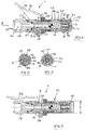
- Fig. 1
- eine Seitenansicht der Kupplungseinrichtung (gemäß Ansicht I in
Fig. 3 ), in nicht manuell betätigtem Zustand, - Fig. 2
- die Kupplungseinrichtung in der Seitenansicht gemäß
Fig. 1 , bei manuell betätigtem Zustand, - Fig. 3
- die Kupplungseinrichtung in einer Ansicht III in
Fig. 1 , - Fig. 4
- einen Schnitt durch die Kupplungseinrichtung gemäß
Fig. 1 , somit bei nicht manuell betätigtem Zustand, gemäß der Schnittlinie IV-IV inFig. 3 , - Fig. 5
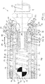
- einen Schnitt V-V gemäß
Fig. 4 , - Fig. 6
- einen Schnitt VI-VI gemäß
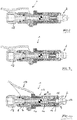
Fig. 4 , - Fig. 7
- die Kupplungseinrichtung in einer Schnittdarstellung gemäß
Fig. 4 für den Zustand nachFig. 2 , somit in manuell betätigtem Zustand, - Fig. 8
- die Kupplungseinrichtung in einer Schnittdarstellung gemäß
Fig. 7 , veranschaulicht für einen mit einem Schmiernippelkopf teilweise in die Kupplungseinrichtung eingeführten Schmiernippel, - Fig. 9
- die Kupplungseinrichtung in der Schnittdarstellung gemäß
Fig. 8 für den vollständig in diese eingeführten Schmiernippelkopf, bei manuell betätigtem Zustand der Kupplungseinrichtung, - Fig. 10
- die Anordnung gemäß
Fig. 9 , bei nicht manuell betätigtem Zustand, somit mit der Kupplungseinrichtung gekuppeltem Schmiernippel, - Fig. 11
- der schmiernippelseitige Bereich der Kupplungseinrichtung in einer vergrößerten Darstellung, mit gekuppeltem Schmiernippel, veranschaulicht für den Zustand gemäß
Fig. 10 .
- Fig. 1
- a side view of the coupling device (according to view I in
Fig. 3 ), in non-manually operated state, - Fig. 2
- the coupling device in the side view according to
Fig. 1 , when manually operated, - Fig. 3
- the coupling device in a view III in
Fig. 1 . - Fig. 4
- a section through the coupling device according to
Fig. 1 , Thus, when not manually operated state, according to the section line IV-IV inFig. 3 . - Fig. 5
- a section VV according to
Fig. 4 . - Fig. 6
- a section VI-VI according to
Fig. 4 . - Fig. 7
- the coupling device in a sectional view according to
Fig. 4 for the condition afterFig. 2 , thus in manually operated condition, - Fig. 8
- the coupling device in a sectional view according to
Fig. 7 , illustrated for a with a grease nipple head partially inserted into the coupling device grease nipple, - Fig. 9
- the coupling device in the sectional view according to
Fig. 8 for the grease nipple head completely inserted into it, with manually operated state of the coupling device, - Fig. 10
- the arrangement according to
Fig. 9 , when not manually actuated state, thus with the coupling device coupled grease nipple, - Fig. 11
- the grease nipple side portion of the coupling device in an enlarged view, with coupled grease nipple, illustrated for the state according to
Fig. 10 ,
Die Kupplungseinrichtung 1 dient dem Verbinden mit einem Schmiernippel 2 im Bereich eines Schmiernippelkopfs 3. Bei diesem Schmiernippel handelt es sich insbesondere um ein Kegelschmiernippel gemäß DIN 71 412, Ausgabe November 1987. Die Kegelschmiernippel können in unterschiedlichen Formen, Form A, Form B, Form C ausgebildet sein. Der Schmiernippel weist den Schmiernippelkopf 3 auf, der, einem Gewindeabschnitt 4 des Schmiernippels 2 abgewandt, einen Kegelstumpfabschnitt 5 aufweist, an den sich, zum Gewindeabschnitt 4 hin, ein nach außen gewölbter Zwischenabschnitt 6 anschließt, der einen Teilbereich einer Kugel darstellt. Dieser Schmiernippel 2 muss nicht über ein Bauteil, das eingeschraubt ist, überstehen, sondern es kann dieses Bauteil ein Sackloch aufweisen, im Bereich dessen der Schmiernippel 2 eingeschraubt ist. Dieses Sackloch weist beispielsweise einen Durchmesser auf, der geringfügig größer als 15 mm ist.The coupling device 1 is used to connect to a
Die Kupplungseinrichtung 1 weist einen Grundkörper 7 auf. Dieser weist eine Einlassöffnung 8 und eine Auslassöffnung 9 sowie einen die Einlassöffnung 8 und die Auslassöffnung 9 verbindenden Durchgang 10 auf. Ferner weist die Kupplungseinrichtung 1, bezogen auf den Durchgang 10, außen in dem Grundkörper 7 schwenkbar gelagerte Kupplungsbacken 11, konkret vier identische Kupplungsbacken 11 auf, die um den Durchgang 10 herum angeordnet sind. Die Kupplungsbacken 11 stehen über die Auslassöffnung 9 hervor und sind in einer ersten Stellung, wie es in den
Die Kupplungseinrichtung 1 weist ferner eine in dem Grundkörper 7 verschieblich gelagerte Schiebehülse 12 auf. Diese ist entgegen einer Federkraft, die durch eine Schraubendruckfeder 13 aufgebracht wird, mittels eines manuell verstellbaren, im Grundkörper 7 und in der Schiebehülse 12 schwenkbar gelagerten Stellmittels 14 verschiebbar, von einer ersten Stellung der Schiebehülse 12, wie sie in den
Der Grundkörper ist im Wesentlichen bezüglich dessen Längsmittelachse 16 rotationssymmetrisch ausgebildet. Sein die Einlassöffnung 8 aufweisendes Ende ist mit einer Aufnahme für einen Drehanschluss 18 ausgebildet. Dieser ist über einen Sicherungsring 19 axial bezüglich des Grundkörpers 7 festgelegt und über einen Dichtring 20 zum Grundkörper 7 hin abgedichtet. Somit kann der Drehanschluss 18 beliebig bezüglich des Grundkörpers 7 um dessen Längsmittelachse 16 gedreht werden. Der Drehanschluss 18 weist im Bereich seines dem Grundkörper 7 abgewandten Endes einen Gewindeanschluss 21 zum festen Verschrauben mit einem komplementären Anschlussteil einer Druckleitung auf, die mit einer Schmierpresse zum Ausgeben von Schmiermittel verbunden ist. Schmiermittel wird somit mittels der Schmierpresse in Richtung des Pfeils B vom Drehanschluss 18 durch die Kupplungseinrichtung 1 zum Schmiernippel 2 gefördert.The main body is essentially rotationally symmetrical with respect to its longitudinal
Den Grundkörper 7 durchsetzt in dessen dem Drehanschluss 18 zugewandten Endbereich eine Lagerachse 21, in der das als Handhebel ausgebildete Stellmittel 14 gelagert ist. Hierbei weist der Handhebel zwei Seitenflanken 22, ferner einen diese verbindenden Steg 23 auf der der Lagerachse 21 abgewandten Seite des Grundkörpers 7 auf. In den dem Steg 23 abgewandten Enden der beiden Seitenflanken 22 ist eine weitere Lagerachse 24 gelagert, die parallel zur Lagerachse 21 in der Schiebehülse 12 gelagert ist. Wird die Kupplungseinrichtung 1 im Bereich des Steges 23 und auf der dem Steg 23 abgewandten Seite des Grundkörpers 7 ergriffen und so betätigt, dass der Steg 23 in Richtung des Grundkörpers 7 geschwenkt wird, führt dies dazu, dass die Schiebehülse 12 von der Einlassöffnung 8 in Richtung des Pfeils B verschoben wird und damit der inneren Kontaktabschnitt 15 der Schiebehülse 12 außer Kontakt mit den Gegenkontaktabschnitten 17 der Klemmbacken 11 gelangt. Hierbei wird die Schraubendruckfeder 13, die in Richtung der Längsmittelachse 16 wirksam ist, zwischen der Schiebehülse 12 und einer Vorspannhülse 25 gespannt. Diese ständig unter Vorspannung stehende Vorspannhülse 25 wirkt auf die Klemmbacken 11 ein. Im Detail ist die Schiebehülse 12 zweiteilig ausgebildet und besteht aus einem vorderen hülsenförmigen Schiebeteil 26 und einem hinteren, in das Schiebeteil 26 eingeschraubten Schiebeteil 27. Beide Schiebeteile 26, 27 sind rotationssymmetrisch ausgebildet. Das Schiebeteil 27 ist radial innen in einem äußeren zylindrischen Mantelabschnitt 28 des Grundkörpers 7 geführt.The
Das Schiebeteil 26 weist im Bereich dessen der Einlassöffnung 8 des Grundkörpers 7 abgewandten Endes, somit im Bereich dessen vorderen Endes, einen nach radial innen gerichteten umlaufenden Ansatz 29 auf. Dieser hintergreift die Klemmbacken 11 im Bereich von der Einlassöffnung 8 abgewandten Stirnflächen 53 und liegt an diesen in der ersten Stellung der Klemmbacken 11 an.The sliding
Die Klemmbacken 11 weisen im Bereich von der Einlassöffnung 8 abgewandten Enden einen nach radial innen gerichteten Ansatz 30 zum Hintergreifen des Schmiernippelkopfs 3 im Bereich des Zwischenabschnitts 6 in der ersten Stellung der Klemmbacken 11 auf. Diese nach innen gerichteten Ansätze 29 der Klemmbacken 11 sind in der ersten Stellung der Klemmbacken 11 innerhalb der Schiebehülse 12 und somit innerhalb des Schiebeteils 26 angeordnet. Die Klemmbacken 11 sind im Bereich von der Einlassöffnung 8 des Grundkörpers 7 zugewandten Enden in einer Außennut 31 des Grundkörpers 7, konkret einer den Mantelabschnitt 28 durchsetzenden Außennut 31 schwenkbar gelagert und hierbei im Grundkörper 7 weitgehend in Bewegungsrichtung der Schiebehülse 12 festgelegt. Hierbei ist die Stärke der Außennut 31 etwas größer als die Abmessung eines Ansatzes 32 des jeweiligen Klemmbackens 11 in dieser Richtung, sodass der jeweilige Klemmbacken geringfügig in Richtung der Doppelpfeile A hin und her beweglich ist, womit ein Schwenken der Klemmbacken 11 möglich ist. In dieser in
Der Durchgang 10 durch den Grundkörper 7 weist zunächst, ausgehend von der Einlassöffnung 8 einen Durchgangsabschnitt 42 auf, dessen Durchmesser wesentlich geringer ist als ein sich bis zur Auslassöffnung 9 anschließender Durchgangsabschnitt 43 des Durchgangs 10. Auch dieser Durchgangsabschnitt 43 weist einen kreisförmigen Querschnitt auf, wobei die Achse die Längsmittelachse 16 ist. Der Durchgangsabschnitt 42 ist mittels eines Rückschlagventils verschließbar. Gezeigt ist eine mittels einer Schraubendruckfeder 44 beaufschlagte Kugel 45, die am Grundkörper 7 im Bereich des Durchgangsabschnitts 42 anliegt. Diese Schraubendruckfeder 44 stützt sich am anderen Ende an einer aus elastischem Material bestehenden Dichtungshülse 46 ab. Diese ist radial außen im Bereich ihres der Schraubendruckfeder 44 zugewandten Endes gegenüber dem Grundkörper 7 abgedichtet, allerdings bezüglich diesem in Richtung der Längsmittelachse 16 verschiebbar. In einem weiter vorne befindlichen Abschnitt der Dichtungshülse 46 nimmt diese radial außen eine aus Metall bestehende Zwischenhülse 47 auf, die radial außen eine umlaufende Nut 48 aufweist. Die Nut 48 nimmt zwei diametral zueinander angeordnete Kugeln 49 auf. Im Bereich der beiden Kugeln 49 ist der Grundkörper 7 mit zwei diesen durchsetzenden Löchern 50 versehen, in denen die Kugeln 49 im Wesentlichen in Axialrichtung und in Tangentialrichtung des Grundkörpers 7 spielfrei geführt sind. Die Nut 48 weist in Längsrichtung A eine Erstreckung auf, die größer ist als der Durchmesser der jeweiligen Kugel 49, und derart abgestimmt ist, dass die Zwischenhülse 47 und damit die Dichtungshülse 46 um ein definiertes Maß beim Einführen des Schmiernippels 2 entgegen der Kraft der Feder 44 verschiebbar sind. Im Bereich des der Einlassöffnung 8 abgewandten Endes weist die Dichtungshülse 46 eine ringförmige Stirnfläche 51 auf, die sich senkrecht zur Längsmittelachse 16 erstreckt und die Gegenkontaktfläche für die freie Stirnfläche des Kegelstumpfabschnitts 5 des Schmiernippelkopfs 3 bildet. Entsprechend der schrägen Kegelgeometrie des Kegelstumpfabschnitts 5 ist die Zwischenhülse 47 in ihrem dem Kegelstumpfabschnitt 5 zugewandten Bereich mit einer Schräge 52 versehen.First, starting from the inlet opening 8, the
Somit wird eine besonders gute Abdichtung im Bereich der Dichtungshülse 46 und des Schmiernippelkopfs 3 erreicht. Die Dichtungshülse 46 ist über die Schraubendruckfeder 44 gegen den veränderlichen Anschlag vorgespannt, der sich aufgrund des Zusammenwirkens von Dichtungshülse 46, Zwischenhülse 47, Nut 48, Kugeln 49, Loch 50 und Grundkörper 7 ergibt.Thus, a particularly good seal in the region of the sealing
Die Wirkungsweise der Kupplungseinrichtung 1 und deren Zusammenwirken mit dem Schmiernippel 2 ergibt sich wie folgt:
Ausgehend von dieser Stellung gemäß
Wird, wie in
Beim weiteren Einschieben des Schmiernippels 2, somit des Schmiernippelkopfes 3 kontaktiert der Kegelstumpfabschnitt 5 die Dichtungshülse 46 im Bereich deren Stirnfläche 51 und verschiebt diese entgegen der Kraft der Schraubendruckfeder 44, die ihrerseits auf die Kugel 45 des Rückschlagventils einwirkt. Die Verschiebung der Dichtungshülse 46 ist aufgrund der Lagerung der Dichtungshülse 46 in der Zwischenhülse 47 und die Verschiebbarkeit der Zwischenhülse in dem Grundkörper 7 infolge des Zusammenwirkens der Nuten 48 und der Kugeln 49 möglich. Die Vorspannhülse 25 hat hierbei auch die Aufgabe, die Kugeln 49 in Richtung radial außen zu fixieren. Der vollständig in die Kupplungseinrichtung 1 eingesteckte Schmiernippel 2 ist in
Ausgehend von diesem Zustand gemäß
Durch die Kupplungseinrichtung 1 und den Schmiernippel 2 kann nun Schmiermittel der zu schmierenden Einheit zugeführt werden. Hierbei herrscht ein üblicher Schmiermitteldruck von 20 bis 100 bar. Es können aber durchaus auch Schmiermitteldrücke über 400 bar anstehen. Aufgrund des Zusammenwirkens des inneren Kontaktabschnitts 15 der Schiebehülse 12 mit den Gegenkontaktabschnitten 17 der Klemmbacken 11 können über den Schmiermitteldruck keine Öffnungskräfte, die zu einem Bewegen der Schiebehülse 12 führen, in diese eingeleitet werden. Die Verbindung von Kupplungseinrichtung 1 und Schmiernippel 2 ist somit sicher und kann nur aufgehoben werden, wenn das Stellmittel 14, im Sinne einer Verschiebung der Schiebehülse 12 nach vorne, betätigt wird. Wird bei einem sehr hohen anstehenden Druck in der Kupplungseinrichtung 1 diese vom Schmiernippel 2 getrennt, bewirkt zunächst die sich nach vorne bewegende Schiebehülse 12, dass der Ausgangsbereich der Dichtungshülse 46 und die Klemmbacken 11 besonders gut abgedeckt werden und einen Spritzschutz bezüglich des Schmiermittels bieten. Ferner wird beim Entkuppeln der Kupplungseinrichtung 1 die Dichtungshülse 46, die unter der Vorspannung der Schraubendruckfeder 44 steht, nachgeführt und liegt damit im Anfangsstadium des Entfernens des Schmiernippelkopfs 3 weiter an diesem an. Ferner werden Druckstöße aus der Schmierpresse, die aufgrund des hohen Drucks an der Schmierpresse auch im Bereich des Drehanschlusses 18 anstehen, aufgrund des relativ geringen Durchmessers des Durchgangsabschnitts 42 minimiert. Hierdurch wird auch die Beanspruchung der Bauteile innerhalb des Grundkörpers 7, konkret Kugel 45, Schraubendruckfeder 44 und Dichtungshülse 46 minimiert.By the coupling device 1 and the
Das Rückschlagventil mit der Kugel 45 hat die Aufgabe, ein Austreten von Schmiermittel zu verhindern, wenn die Kupplungseinrichtung an eine Schmiermittelpresse angeschlossen ist, ohne dass über diese Druck ausgeübt wird.The check valve with the
Wie der Darstellung der
- 11
- Kupplungseinrichtungcoupling device
- 22
- Schmiernippelgrease nipple
- 33
- SchmiernippelkopfLubricating nipple head
- 44
- Gewindeabschnittthreaded portion
- 55
- KegelstumpfabschnittTruncated cone section
- 66
- Zwischenabschnittintermediate section
- 77
- Grundkörperbody
- 88th
- Einlassöffnunginlet port
- 99
- Auslassöffnungoutlet
- 1010
- Durchgangpassage
- 1111
- Klemmbackenjaws
- 1212
- Schiebehülsesliding sleeve
- 1313
- SchraubendruckfederHelical compression spring
- 1414
- Stellmittel/HandhebelActuating means / hand lever
- 1515
- innerer Kontaktabschnittinner contact section
- 1616
- LängsmittelachseLongitudinal central axis
- 1717
- GegenkontaktabchnittGegenkontaktabchnitt
- 1818
- DrehanschlussTorsional connector
- 1919
- Sicherungsringcirclip
- 2020
- Dichtungsringsealing ring
- 2121
- Lagerachsebearing axle
- 2222
- Seitenflankeside flank
- 2323
- Stegweb
- 2424
- Lagerachsebearing axle
- 2525
- Vorspannhülsebiasing sleeve
- 2626
- Schiebeteilsliding part
- 2727
- Schiebeteilsliding part
- 2828
- Mantelabschnittshell section
- 2929
- Ansatzapproach
- 3030
- Ansatzapproach
- 3131
- Außennutouter groove
- 3232
- Ansatzapproach
- 3333
- Vorsprunghead Start
- 3434
- Stirnflächeface
- 3535
- Aussparungrecess
- 3636
- Abschnittsection
- 3737
- Abschnittsection
- 3838
- Abschnittsection
- 3939
- Abschnittsection
- 4040
- Kanteedge
- 4141
- Freiraumfree space
- 4242
- DurchgangsabschnittPassage section
- 4343
- DurchgangsabschnittPassage section
- 4444
- SchraubendruckfederHelical compression spring
- 4545
- KugelBullet
- 4646
- Dichtungshülsegrommet
- 4747
- Zwischenhülseintermediate sleeve
- 4848
- Nutgroove
- 4949
- KugelBullet
- 5050
- Lochhole
- 5151
- Stirnflächeface
- 5252
- Schrägeslope
- 5353
- Stirnflächeface
Claims (12)
- Coupling device (1) for connecting to a lubricating nipple (2) in the region of a lubricating nipple head (3), having a main body (7) which has an inlet opening (8) and an outlet opening (9) and a passage (10) which connects the inlet opening (8) and the outlet opening (9), having, furthermore, clamping jaws (11) which are mounted pivotably in the main body (7) on the outside, in relation to the passage (10), and are arranged around the passage (10), the clamping jaws (11) projecting beyond the outlet opening (9) and being pivoted in in a first position, in order to engage behind the lubricating nipple head (3), and being pivoted out in a second position, in order to release the lubricating nipple head (3), having, furthermore, a sliding sleeve (12) which is mounted displaceably in the main body (7), it being possible for the sliding sleeve (12) to be transferred counter to a spring force by means of an actuating means (14) which is mounted in the main body (7) and the sliding sleeve (12) from a first position, in which the sliding sleeve (12) fixes the clamping jaws (11) in their first position, into a second position, in which the sliding sleeve (12) releases the clamping jaws (11) which are situated in the first position, characterized in that the sliding sleeve (12) has an inner contact section (15) which is arranged parallel to the movement direction (A) of the sliding sleeve (12) during its displacement, the inner contact section (15) bearing, in the first position of the clamping jaws (11) against counter-contact sections (17) of the clamping jaws (11), which counter-contact sections (17) are positioned parallel to the inner contact section (15), and the sliding sleeve (12) being moved, during the movement into its second position, away from the inlet opening (8) of the main body (7) into an out-of-contact position of the inner contact section (15) and the counter-contact sections (17), a spring means (13) being provided which prestresses the clamping jaws (11) into their first position, a prestressing sleeve (25) being arranged between the main body (7) and the sliding sleeve (12), which prestressing sleeve (25) can be displaced in the movement direction (A) of the sliding sleeve (12), the prestressing sleeve (25) acting on the clamping jaws (11) and prestressing the latter into their first position, the spring means (13) being active between the sliding sleeve (12) and the prestressing sleeve (25), the clamping jaws (11) being mounted pivotably, in the region of ends which face the inlet opening (8) of the main body (7), in an outer groove (31) of the main body (7), in a manner which is fixed in the movement direction (A) of the sliding sleeve (12), and the prestressing sleeve (25) acting on the respective clamping jaw (11) at a spacing from the pivot axis (40) of the said respective clamping jaw (11), which spacing generates a pivoting moment.
- Coupling according to Claim 1, characterized in that a spring means (13) which is configured as a compression coil spring is active between the sliding sleeve (12) and the prestressing sleeve (25).
- Coupling device according to either of Claims 1 and 2, characterized in that, on the inside, the sliding sleeve (12) has a circumferential clearance (41) for receiving the clamping jaws (11) in their second position, and, in particular, the clearance (41) is designed in such a way that a pivoting movement of the clamping jaws (11) beyond their second position is blocked.
- Coupling device according to one of Claims 1 to 3, characterized in that, in the region of ends which face away from the inlet opening (8), the clamping jaws (11) have a radially inwardly directed lug (30) for engaging behind the lubricating nipple head (3) in the first position of the clamping jaws (11).
- Coupling device according to Claim 4, characterized in that, in the region of their ends which face away from the inlet opening (8), the clamping jaws (11) are arranged completely within the sliding sleeve (12) in the first and the second position of the clamping jaws (11).
- Coupling device according to Claim 5, characterized in that, in the region of its end which faces away from the inlet opening (8) of the main body (7), the sliding sleeve (12) has a radially inwardly directed, in particular circumferential lug (29), the lug (29) engaging behind the clamping jaws (11) in the region of end faces (54) which face away from the inlet opening (8) of the main body (7), in particular bearing against the said end faces (54) in the first positions of the sliding sleeve (12) and the clamping jaws (11).
- Coupling device according to one of Claims 1 to 6, characterized in that, in the region of the passage (10), the main body (7) receives an elastic sealing sleeve (46) which is mounted displaceably in the main body (7) and/or an intermediate sleeve (47) and is prestressed against a main body-side stop (48, 49, 50, 7) under the action of a spring force in the direction of the outlet opening (9) of the main body (7).
- Coupling device according to Claim 7, characterized in that the spring force which acts on the sealing sleeve (46) is generated by way of a compression coil spring (44) which is active between the sealing sleeve (46) and the main body (7) and, in particular, the compression coil spring (44) is supported on the sealing sleeve (46) and a ball (45), the ball (45) closing, in the closed position, a section (42) of the passage (10), which section (42) faces the inlet opening (8) of the main body (7).
- Coupling device according to one of Claims 1 to 8, characterized in that an upstream section (42) of the passage (10) has a smaller diameter than a downstream section (43) of the passage (10).
- Coupling device according to one of Claims 7 to 9, characterized in that the intermediate sleeve (47), in particular a metallic intermediate sleeve (47), is arranged between the sealing sleeve (46) and the main body (7), the intermediate sleeve (47) having guides (48) which run on the outside in their longitudinal direction for rolling elements (49), in particular for balls (49), which are fixed in the pushing direction (A) of the intermediate sleeve (47) and radially to the outside, in particular are fixed radially to the outside by means of the prestressing sleeve (25).
- Coupling device according to one of Claims 1 to 10, characterized in that the actuating means (14) is a manually adjustable actuating means (14), in particular is a pivoting lever which is mounted pivotably in the main body (7) and, at a spacing from the pivot axis (21) in the main body (7), is mounted pivotably in the sliding sleeve (12).
- Coupling device according to one of Claims 1 to 11, characterized in that, starting from its end which faces away from the inlet opening (8) of the main body (7), the sliding sleeve (12) has a constant external diameter of at most 15 mm over up to a length of more than 20 mm, in particular up to 60 mm.
Priority Applications (3)
| Application Number | Priority Date | Filing Date | Title |
|---|---|---|---|
| ES16188311T ES2700429T3 (en) | 2016-09-12 | 2016-09-12 | Coupling device for connection to a grease nipple |
| EP16188311.1A EP3293436B1 (en) | 2016-09-12 | 2016-09-12 | Coupling device for connecting with a lubricating nipple |
| PCT/EP2017/071947 WO2018046396A1 (en) | 2016-09-12 | 2017-09-01 | Coupling device for connecting to a lubricating nipple |
Applications Claiming Priority (1)
| Application Number | Priority Date | Filing Date | Title |
|---|---|---|---|
| EP16188311.1A EP3293436B1 (en) | 2016-09-12 | 2016-09-12 | Coupling device for connecting with a lubricating nipple |
Publications (2)
| Publication Number | Publication Date |
|---|---|
| EP3293436A1 EP3293436A1 (en) | 2018-03-14 |
| EP3293436B1 true EP3293436B1 (en) | 2018-08-29 |
Family
ID=56920572
Family Applications (1)
| Application Number | Title | Priority Date | Filing Date |
|---|---|---|---|
| EP16188311.1A Active EP3293436B1 (en) | 2016-09-12 | 2016-09-12 | Coupling device for connecting with a lubricating nipple |
Country Status (3)
| Country | Link |
|---|---|
| EP (1) | EP3293436B1 (en) |
| ES (1) | ES2700429T3 (en) |
| WO (1) | WO2018046396A1 (en) |
Families Citing this family (5)
| Publication number | Priority date | Publication date | Assignee | Title |
|---|---|---|---|---|
| TWM545862U (en) * | 2017-04-12 | 2017-07-21 | King Cho Machinery Industrial Co Ltd | Connector structure of grease gun |
| WO2019200452A1 (en) * | 2018-04-18 | 2019-10-24 | Univer-Co (2013) Inc. | Grease gun coupler |
| CN109114407A (en) * | 2018-10-12 | 2019-01-01 | 山西汾西矿业(集团)有限责任公司 | Grease gun internal expansion type pump nozzle |
| CN113915511A (en) * | 2021-11-04 | 2022-01-11 | 中冶长天国际工程有限责任公司 | Mounting seat, filling mechanism and filling equipment of filling gun |
| CN115218109A (en) * | 2022-08-02 | 2022-10-21 | 永康市富宇汽保工具有限公司 | Electric grease gun joint |
Family Cites Families (4)
| Publication number | Priority date | Publication date | Assignee | Title |
|---|---|---|---|---|
| US2070013A (en) * | 1935-04-29 | 1937-02-09 | Min A Max Co Inc | Lubricating apparatus |
| DE2805829A1 (en) | 1978-02-11 | 1979-08-16 | Mato Masch & Metallwaren | Nipple-engaging collet for grease gun - has two-piece jaw biassed inward around nipple by internal housing taper |
| DE29509667U1 (en) | 1995-06-21 | 1995-08-24 | Reiner Chem Fab Gmbh | Connection hose for lubrication presses or the like. |
| DK2531766T3 (en) * | 2009-12-01 | 2017-01-30 | Gurtech (Pty) Ltd | IMPROVED FAT CLUTCH |
-
2016
- 2016-09-12 EP EP16188311.1A patent/EP3293436B1/en active Active
- 2016-09-12 ES ES16188311T patent/ES2700429T3/en active Active
-
2017
- 2017-09-01 WO PCT/EP2017/071947 patent/WO2018046396A1/en active Application Filing
Also Published As
| Publication number | Publication date |
|---|---|
| WO2018046396A1 (en) | 2018-03-15 |
| ES2700429T3 (en) | 2019-02-15 |
| EP3293436A1 (en) | 2018-03-14 |
Similar Documents
| Publication | Publication Date | Title |
|---|---|---|
| EP3293436B1 (en) | Coupling device for connecting with a lubricating nipple | |
| DE112008000328B4 (en) | Quick connector with tolerance adjustment | |
| DE2923902C2 (en) | ||
| DE60220623T2 (en) | pipe Fittings | |
| DE60305236T2 (en) | Connecting device for connecting two pipes | |
| EP3485192B1 (en) | Locking coupling | |
| WO2008145435A1 (en) | Electric plug connector having a sealing element | |
| DE202008002265U1 (en) | Device for expanding pipes | |
| DE19619839C1 (en) | Coupling for connecting hydraulic conduits | |
| DE60017999T2 (en) | Connecting means for connecting a pipe to a tubular body | |
| EP3097336B1 (en) | Play-free insertion connection for pipe lines and hose lines | |
| DE102008051679B4 (en) | Pneumatic brake cylinder | |
| WO2009007165A1 (en) | Charge-air hose | |
| DE102015222640A1 (en) | Coupling element for a coupling for connecting pressure medium lines | |
| EP2843279A2 (en) | Closure element for a blocking device, and blocking device | |
| DE102014111344A1 (en) | jig | |
| EP0754899B1 (en) | Ball-valve with quick-acting connector | |
| DE102013102384B4 (en) | Coaxial high-pressure coupling with effective sealing of the plug part and the receiving part during the coupling process | |
| DE2820168C2 (en) | Seal for a valve spindle | |
| EP2505895A1 (en) | Coupling section of a pressurising agent conduit coupling | |
| DE19809852C2 (en) | Connection device for sanitary pipelines | |
| WO2014079430A1 (en) | Piston-cylinder unit | |
| WO2000003171A1 (en) | Locked socket joint | |
| DE4318840C2 (en) | Coupling for connecting hydraulic lines | |
| EP2103859A1 (en) | Coupling comprised of coupling sections |
Legal Events
| Date | Code | Title | Description |
|---|---|---|---|
| PUAI | Public reference made under article 153(3) epc to a published international application that has entered the european phase |
Free format text: ORIGINAL CODE: 0009012 |
|
| 17P | Request for examination filed |
Effective date: 20170913 |
|
| AK | Designated contracting states |
Kind code of ref document: A1 Designated state(s): AL AT BE BG CH CY CZ DE DK EE ES FI FR GB GR HR HU IE IS IT LI LT LU LV MC MK MT NL NO PL PT RO RS SE SI SK SM TR |
|
| AX | Request for extension of the european patent |
Extension state: BA ME |
|
| GRAP | Despatch of communication of intention to grant a patent |
Free format text: ORIGINAL CODE: EPIDOSNIGR1 |
|
| INTG | Intention to grant announced |
Effective date: 20180403 |
|
| GRAS | Grant fee paid |
Free format text: ORIGINAL CODE: EPIDOSNIGR3 |
|
| GRAA | (expected) grant |
Free format text: ORIGINAL CODE: 0009210 |
|
| AK | Designated contracting states |
Kind code of ref document: B1 Designated state(s): AL AT BE BG CH CY CZ DE DK EE ES FI FR GB GR HR HU IE IS IT LI LT LU LV MC MK MT NL NO PL PT RO RS SE SI SK SM TR |
|
| REG | Reference to a national code |
Ref country code: GB Ref legal event code: FG4D Free format text: NOT ENGLISH |
|
| REG | Reference to a national code |
Ref country code: CH Ref legal event code: EP |
|
| REG | Reference to a national code |
Ref country code: AT Ref legal event code: REF Ref document number: 1035531 Country of ref document: AT Kind code of ref document: T Effective date: 20180915 |
|
| REG | Reference to a national code |
Ref country code: IE Ref legal event code: FG4D Free format text: LANGUAGE OF EP DOCUMENT: GERMAN |
|
| REG | Reference to a national code |
Ref country code: DE Ref legal event code: R096 Ref document number: 502016001803 Country of ref document: DE |
|
| REG | Reference to a national code |
Ref country code: FR Ref legal event code: PLFP Year of fee payment: 3 |
|
| REG | Reference to a national code |
Ref country code: NL Ref legal event code: FP |
|
| REG | Reference to a national code |
Ref country code: LT Ref legal event code: MG4D |
|
| PG25 | Lapsed in a contracting state [announced via postgrant information from national office to epo] |
Ref country code: GR Free format text: LAPSE BECAUSE OF FAILURE TO SUBMIT A TRANSLATION OF THE DESCRIPTION OR TO PAY THE FEE WITHIN THE PRESCRIBED TIME-LIMIT Effective date: 20181130 Ref country code: RS Free format text: LAPSE BECAUSE OF FAILURE TO SUBMIT A TRANSLATION OF THE DESCRIPTION OR TO PAY THE FEE WITHIN THE PRESCRIBED TIME-LIMIT Effective date: 20180829 Ref country code: LT Free format text: LAPSE BECAUSE OF FAILURE TO SUBMIT A TRANSLATION OF THE DESCRIPTION OR TO PAY THE FEE WITHIN THE PRESCRIBED TIME-LIMIT Effective date: 20180829 Ref country code: SE Free format text: LAPSE BECAUSE OF FAILURE TO SUBMIT A TRANSLATION OF THE DESCRIPTION OR TO PAY THE FEE WITHIN THE PRESCRIBED TIME-LIMIT Effective date: 20180829 Ref country code: BG Free format text: LAPSE BECAUSE OF FAILURE TO SUBMIT A TRANSLATION OF THE DESCRIPTION OR TO PAY THE FEE WITHIN THE PRESCRIBED TIME-LIMIT Effective date: 20181129 Ref country code: FI Free format text: LAPSE BECAUSE OF FAILURE TO SUBMIT A TRANSLATION OF THE DESCRIPTION OR TO PAY THE FEE WITHIN THE PRESCRIBED TIME-LIMIT Effective date: 20180829 Ref country code: NO Free format text: LAPSE BECAUSE OF FAILURE TO SUBMIT A TRANSLATION OF THE DESCRIPTION OR TO PAY THE FEE WITHIN THE PRESCRIBED TIME-LIMIT Effective date: 20181129 Ref country code: IS Free format text: LAPSE BECAUSE OF FAILURE TO SUBMIT A TRANSLATION OF THE DESCRIPTION OR TO PAY THE FEE WITHIN THE PRESCRIBED TIME-LIMIT Effective date: 20181229 |
|
| REG | Reference to a national code |
Ref country code: CH Ref legal event code: NV Representative=s name: BOVARD AG PATENT- UND MARKENANWAELTE, CH |
|
| REG | Reference to a national code |
Ref country code: ES Ref legal event code: FG2A Ref document number: 2700429 Country of ref document: ES Kind code of ref document: T3 Effective date: 20190215 |
|
| PG25 | Lapsed in a contracting state [announced via postgrant information from national office to epo] |
Ref country code: LV Free format text: LAPSE BECAUSE OF FAILURE TO SUBMIT A TRANSLATION OF THE DESCRIPTION OR TO PAY THE FEE WITHIN THE PRESCRIBED TIME-LIMIT Effective date: 20180829 Ref country code: HR Free format text: LAPSE BECAUSE OF FAILURE TO SUBMIT A TRANSLATION OF THE DESCRIPTION OR TO PAY THE FEE WITHIN THE PRESCRIBED TIME-LIMIT Effective date: 20180829 Ref country code: AL Free format text: LAPSE BECAUSE OF FAILURE TO SUBMIT A TRANSLATION OF THE DESCRIPTION OR TO PAY THE FEE WITHIN THE PRESCRIBED TIME-LIMIT Effective date: 20180829 |
|
| PG25 | Lapsed in a contracting state [announced via postgrant information from national office to epo] |
Ref country code: EE Free format text: LAPSE BECAUSE OF FAILURE TO SUBMIT A TRANSLATION OF THE DESCRIPTION OR TO PAY THE FEE WITHIN THE PRESCRIBED TIME-LIMIT Effective date: 20180829 Ref country code: IT Free format text: LAPSE BECAUSE OF FAILURE TO SUBMIT A TRANSLATION OF THE DESCRIPTION OR TO PAY THE FEE WITHIN THE PRESCRIBED TIME-LIMIT Effective date: 20180829 Ref country code: RO Free format text: LAPSE BECAUSE OF FAILURE TO SUBMIT A TRANSLATION OF THE DESCRIPTION OR TO PAY THE FEE WITHIN THE PRESCRIBED TIME-LIMIT Effective date: 20180829 Ref country code: CZ Free format text: LAPSE BECAUSE OF FAILURE TO SUBMIT A TRANSLATION OF THE DESCRIPTION OR TO PAY THE FEE WITHIN THE PRESCRIBED TIME-LIMIT Effective date: 20180829 Ref country code: PL Free format text: LAPSE BECAUSE OF FAILURE TO SUBMIT A TRANSLATION OF THE DESCRIPTION OR TO PAY THE FEE WITHIN THE PRESCRIBED TIME-LIMIT Effective date: 20180829 |
|
| PG25 | Lapsed in a contracting state [announced via postgrant information from national office to epo] |
Ref country code: DK Free format text: LAPSE BECAUSE OF FAILURE TO SUBMIT A TRANSLATION OF THE DESCRIPTION OR TO PAY THE FEE WITHIN THE PRESCRIBED TIME-LIMIT Effective date: 20180829 Ref country code: SK Free format text: LAPSE BECAUSE OF FAILURE TO SUBMIT A TRANSLATION OF THE DESCRIPTION OR TO PAY THE FEE WITHIN THE PRESCRIBED TIME-LIMIT Effective date: 20180829 Ref country code: SM Free format text: LAPSE BECAUSE OF FAILURE TO SUBMIT A TRANSLATION OF THE DESCRIPTION OR TO PAY THE FEE WITHIN THE PRESCRIBED TIME-LIMIT Effective date: 20180829 |
|
| REG | Reference to a national code |
Ref country code: DE Ref legal event code: R097 Ref document number: 502016001803 Country of ref document: DE |
|
| REG | Reference to a national code |
Ref country code: BE Ref legal event code: MM Effective date: 20180930 |
|
| REG | Reference to a national code |
Ref country code: IE Ref legal event code: MM4A |
|
| PG25 | Lapsed in a contracting state [announced via postgrant information from national office to epo] |
Ref country code: LU Free format text: LAPSE BECAUSE OF NON-PAYMENT OF DUE FEES Effective date: 20180912 Ref country code: MC Free format text: LAPSE BECAUSE OF FAILURE TO SUBMIT A TRANSLATION OF THE DESCRIPTION OR TO PAY THE FEE WITHIN THE PRESCRIBED TIME-LIMIT Effective date: 20180829 |
|
| PLBE | No opposition filed within time limit |
Free format text: ORIGINAL CODE: 0009261 |
|
| STAA | Information on the status of an ep patent application or granted ep patent |
Free format text: STATUS: NO OPPOSITION FILED WITHIN TIME LIMIT |
|
| PG25 | Lapsed in a contracting state [announced via postgrant information from national office to epo] |
Ref country code: IE Free format text: LAPSE BECAUSE OF NON-PAYMENT OF DUE FEES Effective date: 20180912 |
|
| 26N | No opposition filed |
Effective date: 20190531 |
|
| PG25 | Lapsed in a contracting state [announced via postgrant information from national office to epo] |
Ref country code: SI Free format text: LAPSE BECAUSE OF FAILURE TO SUBMIT A TRANSLATION OF THE DESCRIPTION OR TO PAY THE FEE WITHIN THE PRESCRIBED TIME-LIMIT Effective date: 20180829 Ref country code: BE Free format text: LAPSE BECAUSE OF NON-PAYMENT OF DUE FEES Effective date: 20180930 |
|
| PG25 | Lapsed in a contracting state [announced via postgrant information from national office to epo] |
Ref country code: MT Free format text: LAPSE BECAUSE OF FAILURE TO SUBMIT A TRANSLATION OF THE DESCRIPTION OR TO PAY THE FEE WITHIN THE PRESCRIBED TIME-LIMIT Effective date: 20180829 |
|
| PG25 | Lapsed in a contracting state [announced via postgrant information from national office to epo] |
Ref country code: TR Free format text: LAPSE BECAUSE OF FAILURE TO SUBMIT A TRANSLATION OF THE DESCRIPTION OR TO PAY THE FEE WITHIN THE PRESCRIBED TIME-LIMIT Effective date: 20180829 |
|
| PG25 | Lapsed in a contracting state [announced via postgrant information from national office to epo] |
Ref country code: PT Free format text: LAPSE BECAUSE OF FAILURE TO SUBMIT A TRANSLATION OF THE DESCRIPTION OR TO PAY THE FEE WITHIN THE PRESCRIBED TIME-LIMIT Effective date: 20180829 |
|
| PG25 | Lapsed in a contracting state [announced via postgrant information from national office to epo] |
Ref country code: HU Free format text: LAPSE BECAUSE OF FAILURE TO SUBMIT A TRANSLATION OF THE DESCRIPTION OR TO PAY THE FEE WITHIN THE PRESCRIBED TIME-LIMIT; INVALID AB INITIO Effective date: 20160912 Ref country code: MK Free format text: LAPSE BECAUSE OF NON-PAYMENT OF DUE FEES Effective date: 20180829 Ref country code: CY Free format text: LAPSE BECAUSE OF FAILURE TO SUBMIT A TRANSLATION OF THE DESCRIPTION OR TO PAY THE FEE WITHIN THE PRESCRIBED TIME-LIMIT Effective date: 20180829 |
|
| PGFP | Annual fee paid to national office [announced via postgrant information from national office to epo] |
Ref country code: NL Payment date: 20230920 Year of fee payment: 8 Ref country code: GB Payment date: 20230920 Year of fee payment: 8 Ref country code: AT Payment date: 20230921 Year of fee payment: 8 |
|
| PGFP | Annual fee paid to national office [announced via postgrant information from national office to epo] |
Ref country code: FR Payment date: 20230928 Year of fee payment: 8 |
|
| PGFP | Annual fee paid to national office [announced via postgrant information from national office to epo] |
Ref country code: ES Payment date: 20231124 Year of fee payment: 8 |
|
| PGFP | Annual fee paid to national office [announced via postgrant information from national office to epo] |
Ref country code: DE Payment date: 20231030 Year of fee payment: 8 Ref country code: CH Payment date: 20231001 Year of fee payment: 8 |