EP3293360A1 - Seal system with primary and secondary seal arrangement - Google Patents
Seal system with primary and secondary seal arrangement Download PDFInfo
- Publication number
- EP3293360A1 EP3293360A1 EP17190654.8A EP17190654A EP3293360A1 EP 3293360 A1 EP3293360 A1 EP 3293360A1 EP 17190654 A EP17190654 A EP 17190654A EP 3293360 A1 EP3293360 A1 EP 3293360A1
- Authority
- EP
- European Patent Office
- Prior art keywords
- seal
- runner
- cartridge
- recited
- labyrinth
- Prior art date
- Legal status (The legal status is an assumption and is not a legal conclusion. Google has not performed a legal analysis and makes no representation as to the accuracy of the status listed.)
- Granted
Links
Images



Classifications
-
- F—MECHANICAL ENGINEERING; LIGHTING; HEATING; WEAPONS; BLASTING
- F01—MACHINES OR ENGINES IN GENERAL; ENGINE PLANTS IN GENERAL; STEAM ENGINES
- F01D—NON-POSITIVE DISPLACEMENT MACHINES OR ENGINES, e.g. STEAM TURBINES
- F01D11/00—Preventing or minimising internal leakage of working-fluid, e.g. between stages
- F01D11/003—Preventing or minimising internal leakage of working-fluid, e.g. between stages by packing rings; Mechanical seals
-
- F—MECHANICAL ENGINEERING; LIGHTING; HEATING; WEAPONS; BLASTING
- F01—MACHINES OR ENGINES IN GENERAL; ENGINE PLANTS IN GENERAL; STEAM ENGINES
- F01D—NON-POSITIVE DISPLACEMENT MACHINES OR ENGINES, e.g. STEAM TURBINES
- F01D11/00—Preventing or minimising internal leakage of working-fluid, e.g. between stages
- F01D11/02—Preventing or minimising internal leakage of working-fluid, e.g. between stages by non-contact sealings, e.g. of labyrinth type
-
- F—MECHANICAL ENGINEERING; LIGHTING; HEATING; WEAPONS; BLASTING
- F16—ENGINEERING ELEMENTS AND UNITS; GENERAL MEASURES FOR PRODUCING AND MAINTAINING EFFECTIVE FUNCTIONING OF MACHINES OR INSTALLATIONS; THERMAL INSULATION IN GENERAL
- F16J—PISTONS; CYLINDERS; SEALINGS
- F16J15/00—Sealings
- F16J15/16—Sealings between relatively-moving surfaces
- F16J15/32—Sealings between relatively-moving surfaces with elastic sealings, e.g. O-rings
- F16J15/3284—Sealings between relatively-moving surfaces with elastic sealings, e.g. O-rings characterised by their structure; Selection of materials
- F16J15/3288—Filamentary structures, e.g. brush seals
-
- F—MECHANICAL ENGINEERING; LIGHTING; HEATING; WEAPONS; BLASTING
- F16—ENGINEERING ELEMENTS AND UNITS; GENERAL MEASURES FOR PRODUCING AND MAINTAINING EFFECTIVE FUNCTIONING OF MACHINES OR INSTALLATIONS; THERMAL INSULATION IN GENERAL
- F16J—PISTONS; CYLINDERS; SEALINGS
- F16J15/00—Sealings
- F16J15/44—Free-space packings
- F16J15/447—Labyrinth packings
- F16J15/4472—Labyrinth packings with axial path
-
- F—MECHANICAL ENGINEERING; LIGHTING; HEATING; WEAPONS; BLASTING
- F05—INDEXING SCHEMES RELATING TO ENGINES OR PUMPS IN VARIOUS SUBCLASSES OF CLASSES F01-F04
- F05D—INDEXING SCHEME FOR ASPECTS RELATING TO NON-POSITIVE-DISPLACEMENT MACHINES OR ENGINES, GAS-TURBINES OR JET-PROPULSION PLANTS
- F05D2240/00—Components
- F05D2240/55—Seals
- F05D2240/56—Brush seals
Definitions
- a further embodiment of the present disclosure may include, wherein the labyrinth seal is of a straight canted configuration.
- a further embodiment of the present disclosure may include, wherein the cartridge interfaces with a retention device.
- the cartridge 82 also includes one or more seal lands 102 that may be of various configurations such as a stepped ( Figures 5, and 6 ), a straight configuration ( Figures 6 and 7 ) and a configuration ( Figure 7 ). It should be appreciated that the shape, pitch number, and of the knife edges, as well as various combinations may alternatively be provided. Further, the knife edges can seal against metal or an abrade-able surface and the brush seal bristles can be either metallic, non-metallic material or combinations thereof.
Landscapes
- Engineering & Computer Science (AREA)
- General Engineering & Computer Science (AREA)
- Mechanical Engineering (AREA)
- Sealing Using Fluids, Sealing Without Contact, And Removal Of Oil (AREA)
- Sealing Devices (AREA)
Abstract
Description
- The present disclosure relates to a gas turbine engine and, more particularly, to a seal system therefor.
- Certain sections of gas turbine engines may operate at high temperatures and pressures and some engine components may be sensitive thereto. Typically, seal systems are positioned to prevent the high temperature and pressure air from flowing into sensitive areas and prevent the oil used for cooling and lubrication from escaping the compartment. Such seal system includes either carbon seals and to a lesser extent labyrinth seals.
- Two fundamental purposes of bearing compartment seals are to protect the compartment and its components from the surrounding hostile air environment and to contain the oil within the compartment. Oil that weeps through the carbon seal may travel into the compressor system or turbine. This may not be acceptable since bleeding into the compressor may lead to imbalance concerns or customer bleed contamination while bleeding into the turbine may lead to thermal operational effects. Carbon seals may be prone to wear as a result of a various causes such as coning of the carbon element or seal seat, assembly variation, and operational conditions.
- A seal system for a gas turbine engine according to one disclosed non-limiting embodiment of the present disclosure can include a cartridge; a runner; a first seal between the cartridge and the runner; and a second seal between the cartridge and the runner.
- A further embodiment of the present disclosure may include, wherein the first seal is a brush seal and the second seal is a labyrinth seal.
- A further embodiment of the present disclosure may include, wherein the labyrinth seal is of a stepped canted configuration.
- A further embodiment of the present disclosure may include, wherein the labyrinth seal is of a straight canted configuration.
- A further embodiment of the present disclosure may include, wherein the labyrinth seal is of a staggered knife configuration.
- A further embodiment of the present disclosure may include, wherein the labyrinth seal is of a straight knife configuration.
- A further embodiment of the present disclosure may include 2, wherein the rotor includes a runner upon which the brush seal interfaces.
- A further embodiment of the present disclosure may include, wherein the first seal is a brush seal and the second seal is a windback seal.
- A further embodiment of the present disclosure may include, wherein the cartridge interfaces with a retention device.
- A seal system for a gas turbine engine according to one disclosed non-limiting embodiment of the present disclosure can include a cartridge; a runner; a brush seal between the cartridge and the runner; and a labyrinth seal between the cartridge and the runner.
- A further embodiment of the present disclosure may include, wherein the labyrinth seal is of a stepped canted configuration.
- A further embodiment of the present disclosure may include, wherein the labyrinth seal is of a straight canted configuration.
- A further embodiment of the present disclosure may include, wherein the labyrinth seal is of a staggered knife configuration.
- A further embodiment of the present disclosure may include, wherein the labyrinth seal is of a straight knife configuration.
- A further embodiment of the present disclosure may include, wherein the rotor includes a runner upon which the brush seal interfaces.
- A further embodiment of the present disclosure may include, wherein the cartridge interfaces with a retention device.
- A seal system for a gas turbine engine according to one disclosed non-limiting embodiment of the present disclosure can include a cartridge; a runner; a brush seal between the cartridge and the runner; and a windback seal between the cartridge and the runner.
- A further embodiment of the present disclosure may include, wherein the rotor includes a runner upon which the brush seal interfaces.
- A further embodiment of the present disclosure may include, wherein the rotor includes a surface upon which the windback seal interfaces.
- The foregoing features and elements may be combined in various combinations without exclusivity, unless expressly indicated otherwise. These features and elements as well as the operation of the invention will become more apparent in light of the following description and the accompanying drawings. It should be understood, however, the following description and drawings are intended to be exemplary in nature and non-limiting.
- Various features will become apparent to those skilled in the art from the following detailed description of the disclosed non-limiting embodiment. The drawings that accompany the detailed description can be briefly described as follows:
-
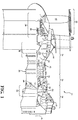
Figure 1 is a schematic cross-section of a gas turbine engine; -
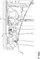
Figure 2 is a longitudinal schematic sectional view of various bearing compartments that may utilize seal systems within the gas turbine engine shown inFigure 1 ; -
Figure 3 is an expanded longitudinal schematic sectional view of a seal system according to one disclosed non-limiting embodiment; -
Figure 4 is an expanded longitudinal schematic sectional view of a seal system according to one disclosed non-limiting embodiment; -
Figure 5 is an expanded longitudinal schematic sectional view of a seal system according to one disclosed non-limiting embodiment; -
Figure 6 is an expanded longitudinal schematic sectional view of a seal system according to one disclosed non-limiting embodiment; -
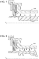
Figure 7 is an expanded longitudinal schematic sectional view of a seal system according to one disclosed non-limiting embodiment; -
Figure 8 is an expanded longitudinal schematic sectional view of a seal system according to one disclosed non-limiting embodiment; -
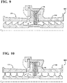
Figure 9 is an expanded longitudinal schematic sectional view of a seal system according to one disclosed non-limiting embodiment; -
Figure 10 is an expanded longitudinal schematic sectional view of a seal system according to one disclosed non-limiting embodiment; -
Figure 11 is an expanded longitudinal schematic sectional view of a seal system according to one disclosed non-limiting embodiment; -
Figure 12 is an expanded longitudinal schematic sectional view of a seal system according to one disclosed non-limiting embodiment; and -
Figure 13 is an expanded longitudinal schematic sectional view of a seal system according to one disclosed non-limiting embodiment. -
Figure 1 schematically illustrates agas turbine engine 20. Thegas turbine engine 20 is disclosed herein as a two-spool turbofan that generally incorporates a fan section 22, acompressor section 24, acombustor section 26 and aturbine section 28. Alternative engine architectures might include an augmentor section and exhaust duct section (not shown) among other systems or features. - The fan section 22 drives air along a bypass flowpath while the
compressor section 24 drives air along a core flowpath for compression and communication into thecombustor section 26 then expansion through theturbine section 28. Although depicted as a turbofan in the disclosed non-limiting embodiment, it should be understood that the concepts described herein are not limited to use with turbofans as the teachings may be applied to other types of turbine engines such as a low bypass augmented turbofan, turbojets, turboshafts, and three-spool (plus fan) turbofans wherein an intermediate spool includes an intermediate pressure compressor ("IPC") between a Low Pressure Compressor ("LPC") and a High Pressure Compressor ("HPC"), and an intermediate pressure turbine ("IPT") between the high pressure turbine ("HPT") and the Low pressure Turbine ("LPT"). - The
engine 20 generally includes alow spool 30 and ahigh spool 32 mounted for rotation about an engine central longitudinal axis A relative to an enginestatic structure 36 viaseveral bearing compartments 38. Thelow spool 30 generally includes aninner shaft 40 that interconnects afan 42, a low pressure compressor 44 ("LPC") and a low pressure turbine 46 ("LPT"). Theinner shaft 40 drives thefan 42 directly or through a gearedarchitecture 48 to drive thefan 42 at a lower speed than thelow spool 30. An exemplary reduction transmission is an epicyclic transmission, namely a planetary or star gear system. Thehigh spool 32 includes anouter shaft 50 that interconnects a high pressure compressor 52 ("HPC") and high pressure turbine 54 ("HPT"). Acombustor 56 is arranged between the HPC 52 and the HPT 54. Theinner shaft 40 and theouter shaft 50 are concentric and rotate about the engine central longitudinal axis A which is collinear with their longitudinal axes. - Core airflow is compressed by the
LPC 44 then the HPC 52, mixed with fuel and burned in thecombustor 56, then expanded over the HPT 54 and theLPT 46. Theturbines low spool 30 andhigh spool 32 in response to the expansion. Themain engine shafts bearing compartments 38. It should be understood thatvarious bearing compartments 38 at various locations may alternatively or additionally be provided. - In one example, the
gas turbine engine 20 is a high-bypass geared aircraft engine with a bypass ratio greater than about six (6:1). The gearedarchitecture 48 can include an epicyclic gear train, such as a planetary gear system or other gear system. The example epicyclic gear train has a gear reduction ratio of greater than about 2.3:1, and in another example is greater than about 2.5:1. The geared turbofan enables operation of thelow spool 30 at higher speeds which can increase the operational efficiency of theLPC 44 andLPT 46 to render increased pressure in a relatively few number of stages. - A pressure ratio associated with the
LPT 46 is pressure measured prior to the inlet of theLPT 46 as related to the pressure at the outlet of theLPT 46 prior to an exhaust nozzle of thegas turbine engine 20. In one non-limiting embodiment, the bypass ratio of thegas turbine engine 20 is greater than about ten (10:1), the fan diameter is significantly larger than that of theLPC 44, and theLPT 46 has a pressure ratio that is greater than about five (5:1). It should be understood, however, that the above parameters are only exemplary of one embodiment of a geared architecture engine and that the present disclosure is applicable to other gas turbine engines including direct drive turbofans, where the rotational speed of thefan 42 is the same (1:1) of theLPC 44. - In one example, a significant amount of thrust is provided by the bypass flow path due to the high bypass ratio. The fan section 22 of the
gas turbine engine 20 is designed for a particular flight condition - typically cruise at about 0.8 Mach and about 35,000 feet (10668M). This flight condition, with thegas turbine engine 20 at its best fuel consumption, is also known as bucket cruise Thrust Specific Fuel Consumption (TSFC). TSFC is an industry standard parameter of fuel consumption per unit of thrust. - Fan Pressure Ratio is the pressure ratio across a blade of the fan section 22 without the use of a Fan Exit Guide Vane system. The relatively low Fan Pressure Ratio according to one example
gas turbine engine 20 is less than 1.45. Low Corrected Fan Tip Speed is the actual fan tip speed divided by an industry standard temperature correction of ("T" / 518.7)0.5 in which "T" represents the ambient temperature in degrees Rankine. The Low Corrected Fan Tip Speed according to one examplegas turbine engine 20 is less than about 1150 fps (351 m/s). - Each of a multiple of bearing
compartments 38 include one or more bearings 60 (illustrated schematically) and one or more seal system 80 (illustrated schematically;Figure 2 ). Thebearings 60 andseal system 80 respectively support and interface with theshafts low spool 30 andhigh spool 32. - The
seal system 80 operates to seal a "wet" zone from a "dry" zone. In other words, regions or volumes that contain oil may be referred to as a "wet" zone and an oil-free region may be referred to as a "dry" zone. So, for example, the interior of each bearingcompartment 38 may be referred to as a wet zone that ultimately communicates with an oil sump while the region external thereto may be referred to as a dry zone. That is, thebearings 60 support thelow spool 30 and thehigh spool 32 and theseal system 80 separate the "wet" zone from the "dry" zone to define the boundaries of each bearingcompartment 38. Although particular bearing compartments and bearing arrangements are illustrated in the disclosed non-limiting embodiment, other bearing compartments and bearing arrangements in other engine architectures such as three-spool architectures will also benefit herefrom. - With reference to
Figure 3 , anexample seal system 80 generally includes acartridge 82, arunner 84, abrush seal 86 between thecartridge 82 and therunner 84 and alabyrinth seal 88 between thecartridge 82 and therunner 84. Theair side 70, or high pressure side, is located adjacent to thebrush seal 86 which may be considered the primary seal while thebearing compartment 72 air/oil side may be considered the low pressure side 74 adjacent to thelabyrinth seal 88 which may be considered the secondary seal. - The
seal system 80 may be utilized, for example, to cap a bearing compartment (sump) for effective oil containment and preclude hot air ingestion into the bearing compartment. Theseal system 80 provides essentially no limit to rotor speed, e.g., over 22,000 rpm; low to no oil cooling requirements at high temperature operating conditions, e.g., 1000F (538C); provides a torturous path for oil to egress; and maintains a healthy delta pressure at operating conditions. - The
cartridge 82 includes an extension 90 to receive aretention device 92 to retain thebrush seal 86 in position. A retainingdevice 94 may also be mounted into static structure 96 to retain thecartridge 82. It should be appreciated that various retainers such as retaining rings, wires, nut(s), bolts, etc., may alternatively or additionally be utilized. That is, aseal land extension 98 and thebrush seal 86 may be arranged as a mini-assembly installed into a larger structure. Alternatively, the seal lands 100 are part of alarger structure 101 such as a housing, support, or cover (Figure 4 ). - The
cartridge 82 also includes one or more seal lands 102 that may be of various configurations such as a stepped (Figures 5, and 6 ), a straight configuration (Figures 6 and7 ) and a configuration (Figure 7 ). It should be appreciated that the shape, pitch number, and of the knife edges, as well as various combinations may alternatively be provided. Further, the knife edges can seal against metal or an abrade-able surface and the brush seal bristles can be either metallic, non-metallic material or combinations thereof. - The
runner 84 includes a multiple of labyrinth seals 104 that interface with the respective seal lands 102. The labyrinth seals 104 may be of various configurations such as a stepped (Figures 2 ), a canted configuration (Figures 5 and 6 ), a staggered knife configuration (Figure 8 ) and a straight knife configuration (Figure 7 ). It should be appreciated that various combinations may alternatively be provided. - With reference to
Figures 9-11 , in other disclosed non-limiting embodiment, a labyrinth seals 104 may be located to flank asingle brush seal 86. In these embodiments, buffer air (illustrated schematically by arrow 106) may be communicated adjacent to thebrush seal 86 on the air cavity side 108 of the seal system 80A-80E. - With reference to
Figures 12-13 , in other disclosed non-limiting embodiment, theseal system windback seal 110. Windback seals work similarly to labyrinth seals except for the effect of helical groove. These seals are essentially a tooth on stator or tooth on rotor labyrinth seal where the grooves are a continuous helical cut like a thread. Windback seals facilitate prevention of oil from a gas face seal area as these face seals cannot be contaminated by oil. A purge gas may be applied to the seal to force the oil back into the bearing area. - Although the different non-limiting embodiments have specific illustrated components, the embodiments of this invention are not limited to those particular combinations. It is possible to use some of the components or features from any of the non-limiting embodiments in combination with features or components from any of the other non-limiting embodiments.
- It should be understood that relative positional terms such as "forward," "aft," "upper," "lower," "above," "below," and the like are with reference to the normal operational attitude of the vehicle and should not be considered otherwise limiting.
- It should be understood that like reference numerals identify corresponding or similar elements throughout the several drawings. It should also be understood that although a particular component arrangement is disclosed in the illustrated embodiment, other arrangements will benefit herefrom.
- Although particular step sequences are shown, described, and claimed, it should be understood that steps may be performed in any order, separated or combined unless otherwise indicated and will still benefit from the present disclosure.
- The foregoing description is exemplary rather than defined by the limitations within. Various non-limiting embodiments are disclosed herein, however, one of ordinary skill in the art would recognize that various modifications and variations in light of the above teachings will fall within the scope of the appended claims. It is therefore to be understood that within the scope of the appended claims, the disclosure may be practiced other than as specifically described. For that reason the appended claims should be studied to determine true scope and content.
Claims (15)
- A seal system for a gas turbine engine comprising:a cartridge;a runner;a first seal between the cartridge and the runner; anda second seal between the cartridge and the runner.
- The system as recited in claim 1, wherein the first seal is a brush seal and the second seal is a labyrinth seal.
- The system as recited in claim 2, wherein the labyrinth seal is of a stepped canted configuration.
- The system as recited in claim 2, wherein the labyrinth seal is of a straight canted configuration.
- The system as recited in claim 2, wherein the labyrinth seal is of a staggered knife configuration.
- The system as recited in claim 2, wherein the labyrinth seal is of a straight knife configuration.
- The system as recited in any one of claims 2-6, wherein the rotor includes a runner upon which the brush seal interfaces.
- The system as recited in claim 1, wherein the first seal is a brush seal and the second seal is a windback seal.
- The system as recited in claim 1, wherein the cartridge interfaces with a retention device.
- A seal system for a gas turbine engine comprising:a cartridge;a runner;a brush seal between the cartridge and the runner; anda labyrinth seal between the cartridge and the runner.
- The system as recited in claim 10, wherein the labyrinth seal is of one of a stepped canted configuration, a straight canted configuration, a staggered knife configuration, or a straight knife configuration.
- The system as recited in claim 10 or 11, wherein the rotor includes a runner upon which the brush seal interfaces.
- The system as recited in claim 10, 11 or 12, wherein the cartridge interfaces with a retention device.
- A seal system for a gas turbine engine comprising:a cartridge;a runner;a brush seal between the cartridge and the runner; anda windback seal between the cartridge and the runner.
- The system as recited in claim 14, wherein the rotor includes a runner upon which the brush seal interfaces, wherein, optionally, the rotor includes a surface upon which the windback seal interfaces.
Applications Claiming Priority (1)
| Application Number | Priority Date | Filing Date | Title |
|---|---|---|---|
| US201662393867P | 2016-09-13 | 2016-09-13 |
Publications (2)
| Publication Number | Publication Date |
|---|---|
| EP3293360A1 true EP3293360A1 (en) | 2018-03-14 |
| EP3293360B1 EP3293360B1 (en) | 2025-10-29 |
Family
ID=59858586
Family Applications (1)
| Application Number | Title | Priority Date | Filing Date |
|---|---|---|---|
| EP17190654.8A Active EP3293360B1 (en) | 2016-09-13 | 2017-09-12 | Seal system with primary and secondary seal arrangement |
Country Status (1)
| Country | Link |
|---|---|
| EP (1) | EP3293360B1 (en) |
Cited By (4)
| Publication number | Priority date | Publication date | Assignee | Title |
|---|---|---|---|---|
| CN108361384A (en) * | 2018-05-18 | 2018-08-03 | 西安交通大学 | A kind of labyrinth seal structure with inner concave shape sealing tooth |
| EP3587742A1 (en) * | 2018-06-27 | 2020-01-01 | MTU Aero Engines GmbH | Rotor for a turbomachine and turbomachine comprising such a rotor |
| US11248492B2 (en) | 2019-03-18 | 2022-02-15 | Raytheon Technologies Corporation | Seal assembly for a gas turbine engine |
| US20240328514A1 (en) * | 2023-03-30 | 2024-10-03 | Raytheon Technologies Corporation | Mistake-proofing for hydrostatic seal assemblies |
Citations (5)
| Publication number | Priority date | Publication date | Assignee | Title |
|---|---|---|---|---|
| US20050098957A1 (en) * | 2003-11-07 | 2005-05-12 | The Boeing Company | Inter-fluid seal assembly and method therefor |
| US20090324388A1 (en) * | 2008-06-30 | 2009-12-31 | Mitsubishi Heavy Industries, Ltd. | Gas turbine and cooling air supply structure thereof |
| US20110038718A1 (en) * | 2009-08-13 | 2011-02-17 | Man Diesel & Turbo Se | Fluid Flow Machine |
| US20130241153A1 (en) * | 2008-05-22 | 2013-09-19 | Stein Seal Company | Windback Device for a Circumferential Seal |
| RU2583480C1 (en) * | 2015-03-12 | 2016-05-10 | федеральное государственное автономное образовательное учреждение высшего образования "Самарский государственный аэрокосмический университет имени академика С.П. Королева (национальный исследовательский университет)" (СГАУ) | Brush seal and method of making same |
Family Cites Families (5)
| Publication number | Priority date | Publication date | Assignee | Title |
|---|---|---|---|---|
| US6390476B1 (en) * | 2000-09-08 | 2002-05-21 | General Electric Company | Heat-resistant magnetic silicone rubber brush seals in turbomachinery and methods of application |
| US7334982B2 (en) * | 2005-05-06 | 2008-02-26 | General Electric Company | Apparatus for scavenging lubricating oil |
| FR2998922B1 (en) * | 2012-12-05 | 2018-06-15 | Safran Aircraft Engines | SEALING OF TURBOMACHINE SPEAKERS REALIZED BY BRUSH JOINT AND LABYRINTH |
| US10557359B2 (en) * | 2016-11-03 | 2020-02-11 | United Technologies Corporation | Seal assembly |
| US11028717B2 (en) * | 2017-06-26 | 2021-06-08 | Raytheon Technologies Corporation | Bearing assembly for gas turbine engines |
-
2017
- 2017-09-12 EP EP17190654.8A patent/EP3293360B1/en active Active
Patent Citations (5)
| Publication number | Priority date | Publication date | Assignee | Title |
|---|---|---|---|---|
| US20050098957A1 (en) * | 2003-11-07 | 2005-05-12 | The Boeing Company | Inter-fluid seal assembly and method therefor |
| US20130241153A1 (en) * | 2008-05-22 | 2013-09-19 | Stein Seal Company | Windback Device for a Circumferential Seal |
| US20090324388A1 (en) * | 2008-06-30 | 2009-12-31 | Mitsubishi Heavy Industries, Ltd. | Gas turbine and cooling air supply structure thereof |
| US20110038718A1 (en) * | 2009-08-13 | 2011-02-17 | Man Diesel & Turbo Se | Fluid Flow Machine |
| RU2583480C1 (en) * | 2015-03-12 | 2016-05-10 | федеральное государственное автономное образовательное учреждение высшего образования "Самарский государственный аэрокосмический университет имени академика С.П. Королева (национальный исследовательский университет)" (СГАУ) | Brush seal and method of making same |
Cited By (6)
| Publication number | Priority date | Publication date | Assignee | Title |
|---|---|---|---|---|
| CN108361384A (en) * | 2018-05-18 | 2018-08-03 | 西安交通大学 | A kind of labyrinth seal structure with inner concave shape sealing tooth |
| EP3587742A1 (en) * | 2018-06-27 | 2020-01-01 | MTU Aero Engines GmbH | Rotor for a turbomachine and turbomachine comprising such a rotor |
| US11280210B2 (en) | 2018-06-27 | 2022-03-22 | MTU Aero Engines AG | Rotor for a turbomachine, and turbomachine having such a rotor |
| US11248492B2 (en) | 2019-03-18 | 2022-02-15 | Raytheon Technologies Corporation | Seal assembly for a gas turbine engine |
| US20240328514A1 (en) * | 2023-03-30 | 2024-10-03 | Raytheon Technologies Corporation | Mistake-proofing for hydrostatic seal assemblies |
| US12188563B2 (en) * | 2023-03-30 | 2025-01-07 | Rtx Corporation | Mistake-proofing for hydrostatic seal assemblies |
Also Published As
| Publication number | Publication date |
|---|---|
| EP3293360B1 (en) | 2025-10-29 |
Similar Documents
| Publication | Publication Date | Title |
|---|---|---|
| EP2809908B1 (en) | Mid-turbine frame buffer system | |
| EP2971663B1 (en) | Oil transfer passage arrangement for a shaft of a gas turbine engine | |
| EP3808947B1 (en) | Geared turbomachine fluid delivery system | |
| EP2964935B1 (en) | Fluid-cooled seal arrangement for a gas turbine engine | |
| EP3702586B1 (en) | Gas turbine engine including seal plate providing increased cooling adjacent contact area | |
| US20140140824A1 (en) | Oil system bearing compartment architecture for gas turbine engine | |
| EP3318722B1 (en) | Seal assembly for a rotatable component | |
| EP3239472B1 (en) | Seal arc segment with sloped circumferential sides | |
| US20140119887A1 (en) | Fluid-cooled seal arrangement for a gas turbine engine | |
| EP2914832B1 (en) | Gas turbine engine with bearing compartment wall cooling | |
| US20140241851A1 (en) | Axial oil scoop for a gas turbine engine | |
| WO2014051691A1 (en) | Buffer airflow to bearing compartment | |
| EP2971677B1 (en) | Triple flange arrangement for a gas turbine engine | |
| EP3293360B1 (en) | Seal system with primary and secondary seal arrangement | |
| US10669890B2 (en) | Compartment shielding | |
| EP3084180B1 (en) | Transfer bearing for geared turbofan | |
| EP3719268B1 (en) | Seal runner with deflector and catcher for gas turbine engine | |
| EP3045681B1 (en) | Gas turbine engine with high temperature spool and associated cooling system | |
| EP2912290B1 (en) | High pressure compressor with cooled casing flanges | |
| EP3000968A2 (en) | Rotor disk assembly for a gas turbine engine | |
| EP3708794B1 (en) | Dual radial scoop oil delivery system | |
| EP2927429B1 (en) | Gas turbine engine component with flow separating rib | |
| EP2955332B1 (en) | Geared turbofan engine with gearbox seal | |
| WO2014143876A1 (en) | Bearing cage lubrication architecture | |
| EP3783203B1 (en) | Gas turbine engine component comprising a radial seal arrangement with axially elongated oil cooled runner |
Legal Events
| Date | Code | Title | Description |
|---|---|---|---|
| PUAI | Public reference made under article 153(3) epc to a published international application that has entered the european phase |
Free format text: ORIGINAL CODE: 0009012 |
|
| STAA | Information on the status of an ep patent application or granted ep patent |
Free format text: STATUS: THE APPLICATION HAS BEEN PUBLISHED |
|
| AK | Designated contracting states |
Kind code of ref document: A1 Designated state(s): AL AT BE BG CH CY CZ DE DK EE ES FI FR GB GR HR HU IE IS IT LI LT LU LV MC MK MT NL NO PL PT RO RS SE SI SK SM TR |
|
| AX | Request for extension of the european patent |
Extension state: BA ME |
|
| STAA | Information on the status of an ep patent application or granted ep patent |
Free format text: STATUS: REQUEST FOR EXAMINATION WAS MADE |
|
| 17P | Request for examination filed |
Effective date: 20180912 |
|
| RBV | Designated contracting states (corrected) |
Designated state(s): AL AT BE BG CH CY CZ DE DK EE ES FI FR GB GR HR HU IE IS IT LI LT LU LV MC MK MT NL NO PL PT RO RS SE SI SK SM TR |
|
| STAA | Information on the status of an ep patent application or granted ep patent |
Free format text: STATUS: EXAMINATION IS IN PROGRESS |
|
| 17Q | First examination report despatched |
Effective date: 20190208 |
|
| RAP1 | Party data changed (applicant data changed or rights of an application transferred) |
Owner name: RAYTHEON TECHNOLOGIES CORPORATION |
|
| RAP3 | Party data changed (applicant data changed or rights of an application transferred) |
Owner name: RTX CORPORATION |
|
| GRAP | Despatch of communication of intention to grant a patent |
Free format text: ORIGINAL CODE: EPIDOSNIGR1 |
|
| STAA | Information on the status of an ep patent application or granted ep patent |
Free format text: STATUS: GRANT OF PATENT IS INTENDED |
|
| INTG | Intention to grant announced |
Effective date: 20241104 |
|
| GRAJ | Information related to disapproval of communication of intention to grant by the applicant or resumption of examination proceedings by the epo deleted |
Free format text: ORIGINAL CODE: EPIDOSDIGR1 |
|
| STAA | Information on the status of an ep patent application or granted ep patent |
Free format text: STATUS: EXAMINATION IS IN PROGRESS |
|
| INTC | Intention to grant announced (deleted) | ||
| GRAP | Despatch of communication of intention to grant a patent |
Free format text: ORIGINAL CODE: EPIDOSNIGR1 |
|
| STAA | Information on the status of an ep patent application or granted ep patent |
Free format text: STATUS: GRANT OF PATENT IS INTENDED |
|
| INTG | Intention to grant announced |
Effective date: 20250415 |
|
| GRAS | Grant fee paid |
Free format text: ORIGINAL CODE: EPIDOSNIGR3 |
|
| GRAA | (expected) grant |
Free format text: ORIGINAL CODE: 0009210 |
|
| STAA | Information on the status of an ep patent application or granted ep patent |
Free format text: STATUS: THE PATENT HAS BEEN GRANTED |
|
| AK | Designated contracting states |
Kind code of ref document: B1 Designated state(s): AL AT BE BG CH CY CZ DE DK EE ES FI FR GB GR HR HU IE IS IT LI LT LU LV MC MK MT NL NO PL PT RO RS SE SI SK SM TR |
|
| REG | Reference to a national code |
Ref country code: CH Ref legal event code: F10 Free format text: ST27 STATUS EVENT CODE: U-0-0-F10-F00 (AS PROVIDED BY THE NATIONAL OFFICE) Effective date: 20251029 Ref country code: GB Ref legal event code: FG4D |
|
| REG | Reference to a national code |
Ref country code: IE Ref legal event code: FG4D |
|
| REG | Reference to a national code |
Ref country code: DE Ref legal event code: R096 Ref document number: 602017092389 Country of ref document: DE |
|
| REG | Reference to a national code |
Ref country code: NL Ref legal event code: MP Effective date: 20251029 |
|
| PG25 | Lapsed in a contracting state [announced via postgrant information from national office to epo] |
Ref country code: ES Free format text: LAPSE BECAUSE OF FAILURE TO SUBMIT A TRANSLATION OF THE DESCRIPTION OR TO PAY THE FEE WITHIN THE PRESCRIBED TIME-LIMIT Effective date: 20251029 |
|
| REG | Reference to a national code |
Ref country code: LT Ref legal event code: MG9D |
|
| PG25 | Lapsed in a contracting state [announced via postgrant information from national office to epo] |
Ref country code: NO Free format text: LAPSE BECAUSE OF FAILURE TO SUBMIT A TRANSLATION OF THE DESCRIPTION OR TO PAY THE FEE WITHIN THE PRESCRIBED TIME-LIMIT Effective date: 20260129 |
|
| PG25 | Lapsed in a contracting state [announced via postgrant information from national office to epo] |
Ref country code: AT Free format text: LAPSE BECAUSE OF FAILURE TO SUBMIT A TRANSLATION OF THE DESCRIPTION OR TO PAY THE FEE WITHIN THE PRESCRIBED TIME-LIMIT Effective date: 20251029 Ref country code: HR Free format text: LAPSE BECAUSE OF FAILURE TO SUBMIT A TRANSLATION OF THE DESCRIPTION OR TO PAY THE FEE WITHIN THE PRESCRIBED TIME-LIMIT Effective date: 20251029 Ref country code: FI Free format text: LAPSE BECAUSE OF FAILURE TO SUBMIT A TRANSLATION OF THE DESCRIPTION OR TO PAY THE FEE WITHIN THE PRESCRIBED TIME-LIMIT Effective date: 20251029 |
|
| REG | Reference to a national code |
Ref country code: AT Ref legal event code: MK05 Ref document number: 1851768 Country of ref document: AT Kind code of ref document: T Effective date: 20251029 |
|
| PG25 | Lapsed in a contracting state [announced via postgrant information from national office to epo] |
Ref country code: NL Free format text: LAPSE BECAUSE OF FAILURE TO SUBMIT A TRANSLATION OF THE DESCRIPTION OR TO PAY THE FEE WITHIN THE PRESCRIBED TIME-LIMIT Effective date: 20251029 |
|
| PG25 | Lapsed in a contracting state [announced via postgrant information from national office to epo] |
Ref country code: RS Free format text: LAPSE BECAUSE OF FAILURE TO SUBMIT A TRANSLATION OF THE DESCRIPTION OR TO PAY THE FEE WITHIN THE PRESCRIBED TIME-LIMIT Effective date: 20260129 |
|
| PG25 | Lapsed in a contracting state [announced via postgrant information from national office to epo] |
Ref country code: IS Free format text: LAPSE BECAUSE OF FAILURE TO SUBMIT A TRANSLATION OF THE DESCRIPTION OR TO PAY THE FEE WITHIN THE PRESCRIBED TIME-LIMIT Effective date: 20260228 |
|
| PG25 | Lapsed in a contracting state [announced via postgrant information from national office to epo] |
Ref country code: PT Free format text: LAPSE BECAUSE OF FAILURE TO SUBMIT A TRANSLATION OF THE DESCRIPTION OR TO PAY THE FEE WITHIN THE PRESCRIBED TIME-LIMIT Effective date: 20260302 |
|
| PG25 | Lapsed in a contracting state [announced via postgrant information from national office to epo] |
Ref country code: PL Free format text: LAPSE BECAUSE OF FAILURE TO SUBMIT A TRANSLATION OF THE DESCRIPTION OR TO PAY THE FEE WITHIN THE PRESCRIBED TIME-LIMIT Effective date: 20251029 |
|
| PG25 | Lapsed in a contracting state [announced via postgrant information from national office to epo] |
Ref country code: LV Free format text: LAPSE BECAUSE OF FAILURE TO SUBMIT A TRANSLATION OF THE DESCRIPTION OR TO PAY THE FEE WITHIN THE PRESCRIBED TIME-LIMIT Effective date: 20251029 |
|
| PG25 | Lapsed in a contracting state [announced via postgrant information from national office to epo] |
Ref country code: BG Free format text: LAPSE BECAUSE OF FAILURE TO SUBMIT A TRANSLATION OF THE DESCRIPTION OR TO PAY THE FEE WITHIN THE PRESCRIBED TIME-LIMIT Effective date: 20251029 |
|
| PG25 | Lapsed in a contracting state [announced via postgrant information from national office to epo] |
Ref country code: LT Free format text: LAPSE BECAUSE OF FAILURE TO SUBMIT A TRANSLATION OF THE DESCRIPTION OR TO PAY THE FEE WITHIN THE PRESCRIBED TIME-LIMIT Effective date: 20251029 |
|
| PG25 | Lapsed in a contracting state [announced via postgrant information from national office to epo] |
Ref country code: SM Free format text: LAPSE BECAUSE OF FAILURE TO SUBMIT A TRANSLATION OF THE DESCRIPTION OR TO PAY THE FEE WITHIN THE PRESCRIBED TIME-LIMIT Effective date: 20251029 |
|
| PG25 | Lapsed in a contracting state [announced via postgrant information from national office to epo] |
Ref country code: DK Free format text: LAPSE BECAUSE OF FAILURE TO SUBMIT A TRANSLATION OF THE DESCRIPTION OR TO PAY THE FEE WITHIN THE PRESCRIBED TIME-LIMIT Effective date: 20251029 |
|
| PG25 | Lapsed in a contracting state [announced via postgrant information from national office to epo] |
Ref country code: IT Free format text: LAPSE BECAUSE OF FAILURE TO SUBMIT A TRANSLATION OF THE DESCRIPTION OR TO PAY THE FEE WITHIN THE PRESCRIBED TIME-LIMIT Effective date: 20251029 |
|
| PG25 | Lapsed in a contracting state [announced via postgrant information from national office to epo] |
Ref country code: EE Free format text: LAPSE BECAUSE OF FAILURE TO SUBMIT A TRANSLATION OF THE DESCRIPTION OR TO PAY THE FEE WITHIN THE PRESCRIBED TIME-LIMIT Effective date: 20251029 |
|
| PG25 | Lapsed in a contracting state [announced via postgrant information from national office to epo] |
Ref country code: CZ Free format text: LAPSE BECAUSE OF FAILURE TO SUBMIT A TRANSLATION OF THE DESCRIPTION OR TO PAY THE FEE WITHIN THE PRESCRIBED TIME-LIMIT Effective date: 20251029 |
|
| PG25 | Lapsed in a contracting state [announced via postgrant information from national office to epo] |
Ref country code: SK Free format text: LAPSE BECAUSE OF FAILURE TO SUBMIT A TRANSLATION OF THE DESCRIPTION OR TO PAY THE FEE WITHIN THE PRESCRIBED TIME-LIMIT Effective date: 20251029 |
|
| PG25 | Lapsed in a contracting state [announced via postgrant information from national office to epo] |
Ref country code: SE Free format text: LAPSE BECAUSE OF FAILURE TO SUBMIT A TRANSLATION OF THE DESCRIPTION OR TO PAY THE FEE WITHIN THE PRESCRIBED TIME-LIMIT Effective date: 20251029 |