EP3293358A1 - Airfoil retention assembly for a gas turbine engine - Google Patents
Airfoil retention assembly for a gas turbine engine Download PDFInfo
- Publication number
- EP3293358A1 EP3293358A1 EP17189637.6A EP17189637A EP3293358A1 EP 3293358 A1 EP3293358 A1 EP 3293358A1 EP 17189637 A EP17189637 A EP 17189637A EP 3293358 A1 EP3293358 A1 EP 3293358A1
- Authority
- EP
- European Patent Office
- Prior art keywords
- ring
- retaining
- length
- disk
- array
- Prior art date
- Legal status (The legal status is an assumption and is not a legal conclusion. Google has not performed a legal analysis and makes no representation as to the accuracy of the status listed.)
- Granted
Links
Images





Classifications
-
- F—MECHANICAL ENGINEERING; LIGHTING; HEATING; WEAPONS; BLASTING
- F01—MACHINES OR ENGINES IN GENERAL; ENGINE PLANTS IN GENERAL; STEAM ENGINES
- F01D—NON-POSITIVE DISPLACEMENT MACHINES OR ENGINES, e.g. STEAM TURBINES
- F01D5/00—Blades; Blade-carrying members; Heating, heat-insulating, cooling or antivibration means on the blades or the members
- F01D5/30—Fixing blades to rotors; Blade roots ; Blade spacers
- F01D5/3023—Fixing blades to rotors; Blade roots ; Blade spacers of radial insertion type, e.g. in individual recesses
-
- F—MECHANICAL ENGINEERING; LIGHTING; HEATING; WEAPONS; BLASTING
- F01—MACHINES OR ENGINES IN GENERAL; ENGINE PLANTS IN GENERAL; STEAM ENGINES
- F01D—NON-POSITIVE DISPLACEMENT MACHINES OR ENGINES, e.g. STEAM TURBINES
- F01D5/00—Blades; Blade-carrying members; Heating, heat-insulating, cooling or antivibration means on the blades or the members
- F01D5/02—Blade-carrying members, e.g. rotors
- F01D5/06—Rotors for more than one axial stage, e.g. of drum or multiple disc type; Details thereof, e.g. shafts, shaft connections
-
- F—MECHANICAL ENGINEERING; LIGHTING; HEATING; WEAPONS; BLASTING
- F01—MACHINES OR ENGINES IN GENERAL; ENGINE PLANTS IN GENERAL; STEAM ENGINES
- F01D—NON-POSITIVE DISPLACEMENT MACHINES OR ENGINES, e.g. STEAM TURBINES
- F01D5/00—Blades; Blade-carrying members; Heating, heat-insulating, cooling or antivibration means on the blades or the members
- F01D5/12—Blades
-
- F—MECHANICAL ENGINEERING; LIGHTING; HEATING; WEAPONS; BLASTING
- F01—MACHINES OR ENGINES IN GENERAL; ENGINE PLANTS IN GENERAL; STEAM ENGINES
- F01D—NON-POSITIVE DISPLACEMENT MACHINES OR ENGINES, e.g. STEAM TURBINES
- F01D5/00—Blades; Blade-carrying members; Heating, heat-insulating, cooling or antivibration means on the blades or the members
- F01D5/30—Fixing blades to rotors; Blade roots ; Blade spacers
- F01D5/3007—Fixing blades to rotors; Blade roots ; Blade spacers of axial insertion type
- F01D5/3015—Fixing blades to rotors; Blade roots ; Blade spacers of axial insertion type with side plates
-
- F—MECHANICAL ENGINEERING; LIGHTING; HEATING; WEAPONS; BLASTING
- F01—MACHINES OR ENGINES IN GENERAL; ENGINE PLANTS IN GENERAL; STEAM ENGINES
- F01D—NON-POSITIVE DISPLACEMENT MACHINES OR ENGINES, e.g. STEAM TURBINES
- F01D5/00—Blades; Blade-carrying members; Heating, heat-insulating, cooling or antivibration means on the blades or the members
- F01D5/30—Fixing blades to rotors; Blade roots ; Blade spacers
- F01D5/32—Locking, e.g. by final locking blades or keys
- F01D5/326—Locking of axial insertion type blades by other means
-
- F—MECHANICAL ENGINEERING; LIGHTING; HEATING; WEAPONS; BLASTING
- F04—POSITIVE - DISPLACEMENT MACHINES FOR LIQUIDS; PUMPS FOR LIQUIDS OR ELASTIC FLUIDS
- F04D—NON-POSITIVE-DISPLACEMENT PUMPS
- F04D19/00—Axial-flow pumps
- F04D19/02—Multi-stage pumps
-
- F—MECHANICAL ENGINEERING; LIGHTING; HEATING; WEAPONS; BLASTING
- F04—POSITIVE - DISPLACEMENT MACHINES FOR LIQUIDS; PUMPS FOR LIQUIDS OR ELASTIC FLUIDS
- F04D—NON-POSITIVE-DISPLACEMENT PUMPS
- F04D25/00—Pumping installations or systems
- F04D25/02—Units comprising pumps and their driving means
- F04D25/04—Units comprising pumps and their driving means the pump being fluid-driven
- F04D25/045—Units comprising pumps and their driving means the pump being fluid-driven the pump wheel carrying the fluid driving means, e.g. turbine blades
-
- F—MECHANICAL ENGINEERING; LIGHTING; HEATING; WEAPONS; BLASTING
- F05—INDEXING SCHEMES RELATING TO ENGINES OR PUMPS IN VARIOUS SUBCLASSES OF CLASSES F01-F04
- F05D—INDEXING SCHEME FOR ASPECTS RELATING TO NON-POSITIVE-DISPLACEMENT MACHINES OR ENGINES, GAS-TURBINES OR JET-PROPULSION PLANTS
- F05D2220/00—Application
- F05D2220/30—Application in turbines
- F05D2220/32—Application in turbines in gas turbines
-
- F—MECHANICAL ENGINEERING; LIGHTING; HEATING; WEAPONS; BLASTING
- F05—INDEXING SCHEMES RELATING TO ENGINES OR PUMPS IN VARIOUS SUBCLASSES OF CLASSES F01-F04
- F05D—INDEXING SCHEME FOR ASPECTS RELATING TO NON-POSITIVE-DISPLACEMENT MACHINES OR ENGINES, GAS-TURBINES OR JET-PROPULSION PLANTS
- F05D2230/00—Manufacture
- F05D2230/60—Assembly methods
-
- F—MECHANICAL ENGINEERING; LIGHTING; HEATING; WEAPONS; BLASTING
- F05—INDEXING SCHEMES RELATING TO ENGINES OR PUMPS IN VARIOUS SUBCLASSES OF CLASSES F01-F04
- F05D—INDEXING SCHEME FOR ASPECTS RELATING TO NON-POSITIVE-DISPLACEMENT MACHINES OR ENGINES, GAS-TURBINES OR JET-PROPULSION PLANTS
- F05D2260/00—Function
- F05D2260/30—Retaining components in desired mutual position
-
- F—MECHANICAL ENGINEERING; LIGHTING; HEATING; WEAPONS; BLASTING
- F05—INDEXING SCHEMES RELATING TO ENGINES OR PUMPS IN VARIOUS SUBCLASSES OF CLASSES F01-F04
- F05D—INDEXING SCHEME FOR ASPECTS RELATING TO NON-POSITIVE-DISPLACEMENT MACHINES OR ENGINES, GAS-TURBINES OR JET-PROPULSION PLANTS
- F05D2260/00—Function
- F05D2260/30—Retaining components in desired mutual position
- F05D2260/36—Retaining components in desired mutual position by a form fit connection, e.g. by interlocking
Definitions
- This application relates generally to retention of airfoils in a gas turbine engine.
- a gas turbine engine typically includes a fan section, a compressor section, a combustor section and a turbine section. Air entering the compressor section is compressed and delivered into the combustion section where it is mixed with fuel and ignited to generate a high-speed exhaust gas flow. The high-speed exhaust gas flow expands through the turbine section to drive the compressor and the fan section.
- the compressor section typically includes low and high pressure compressors, and the turbine section includes low and high pressure turbines.
- the compressor and turbine sections can include one or more airfoil disks configured to carry an array of airfoils to compress or extract energy from the gas flow.
- An airfoil retention assembly for a gas turbine engine includes a disk defining a disk axis and an array of slots configured to receive an array of blades, a coverplate dimensioned to radially overlap the array of slots relative to the disk axis, and a retaining ring that has a ring body extending circumferentially about the disk axis between first and second ring ends to define a ring length.
- a first retaining feature continues along a first circumferential face of the ring body to define a first length
- a second retaining feature continues along a second circumferential face of the ring body to define a second length. At least one of the first length and second length is less than the ring length.
- a difference between the ring length and the first length is at least 1.5% of the ring length.
- the retaining ring is configured such that the first ring end abuts first and second retaining ends of the first retaining feature in a compressed state.
- the first and second ring ends define a circumferential gap in an uncompressed state.
- the circumferential gap is less than 1% of the ring length.
- the circumferential gap is between 0.2% and 0.4% of the ring length in the uncompressed state.
- the first retaining feature and the second retaining feature are configured to limit radial movement of the coverplate relative to the disk axis.
- the coverplate is dimensioned to abut a radially extending face of the disk.
- both the first length and the second length are less than the ring length.
- the disk includes a disk arm that defines a circumferentially extending ridge dimensioned to receive at least a portion of the retaining ring.
- a gas turbine engine includes a compressor section that has a first compressor and a second compressor, a turbine section configured to drive the compressor section, and a retention assembly that has a disk defining a disk axis and including an array of slots configured to receive an array of blades, a coverplate configured to abut the array of blades adjacent to the array of slots, and a retaining ring that has a ring body extending circumferentially between first and second ring ends to define a ring length.
- a first retaining feature extends circumferentially between a first retaining end and a second retaining end. At least one of the first and second retaining ends are circumferentially spaced apart from the first and second ring ends.
- a first differential length is defined between the first ring end and the first retaining end.
- a second differential length is defined between the second ring end and the second retaining end. The first differential length and the second differential length is at least 1.5% of the ring length.
- the retaining ring is configured such that the first ring end abuts the first retaining end in a compressed state, but is spaced apart from the first retaining end in an uncompressed state.
- the retention assembly is a plurality of retention assemblies each defining a corresponding turbine stage.
- the disk includes a disk arm and a circumferentially extending ridge dimensioned to receive at least a portion of the retaining ring.
- the retaining ring includes a second retaining feature extending circumferentially between a third retaining end and a fourth retaining end, the second retaining feature dimensioned to abut a radially extending portion of the disk arm.
- the first retaining feature and the second retaining feature are configured to limit radial movement of the coverplate relative to the disk axis.
- a method of retaining an airfoil in a gas turbine engine includes providing a disk defining a disk axis, and having a radially extending disk face.
- a disk arm defines a circumferentially extending ridge, and an array of slots configured to receive an array of blades, moving at least one blade of the array of blades into one slot of the array of slots, moving a coverplate along the disk axis to abut the disk face, and situating a retaining ring at least partially in the circumferentially extending ridge the retaining ring including a ring body extending circumferentially about the disk axis between first and second ring ends to define a ring length.
- a first retaining feature continues along a first circumferential face of the retaining ring to define a first length. The first length is less than the ring length.
- a further embodiment of any of the foregoing embodiments includes compressing the retaining ring around the disk arm such that the first ring end abuts an end of the first retaining feature, and decompressing the retaining ring such that the retaining ring limits axial movement of the coverplate along the disk axis.
- the step of decompressing includes defining a circumferential gap between the first and second ring ends, the circumferential gap being less than 1% of the ring length.
- the retaining ring includes a second retaining feature continuing along a second circumferential face of the retaining ring.
- the first retaining feature is dimensioned to abut an inner edge of the coverplate and the second retaining feature is dimensioned to abut a radially extending portion of the disk arm.
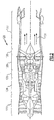
- FIG. 1 schematically illustrates a gas turbine engine 20 for use in a commercial aircraft, for example.
- the gas turbine engine 20 is disclosed herein as a two-spool turbofan that generally incorporates a fan section 22, a compressor section 24, a combustor section 26 and a turbine section 28.
- Alternative engines might include an augmenter section (not shown) among other systems or features.
- the fan section 22 drives air along a bypass flow path B in a bypass duct defined within a nacelle 15, while the compressor section 24 drives air along a core flow path C for compression and communication into the combustor section 26 then expansion through the turbine section 28.
- the exemplary engine 20 generally includes a low speed spool 30 and a high speed spool 32 mounted for rotation about an engine central longitudinal axis X relative to an engine static structure 36 via several bearing systems 38. It should be understood that various bearing systems 38 at various locations may alternatively or additionally be provided, and the location of bearing systems 38 may be varied as appropriate to the application.
- the low speed spool 30 generally includes an inner shaft 40 that interconnects a fan 42, a first (or low) pressure compressor 44 and a first (or low) pressure turbine 46.
- the inner shaft 40 is connected to the fan 42 through a speed change mechanism, which in exemplary gas turbine engine 20 is illustrated as a geared architecture 48 to drive the fan 42 at a lower speed than the low speed spool 30.
- the high speed spool 32 includes an outer shaft 50 that interconnects a second (or high) pressure compressor 52 and a second (or high) pressure turbine 54.
- a combustor 56 is arranged in exemplary gas turbine 20 between the high pressure compressor 52 and the high pressure turbine 54.
- a mid-turbine frame 57 of the engine static structure 36 is arranged generally between the high pressure turbine 54 and the low pressure turbine 46.
- the mid-turbine frame 57 further supports bearing systems 38 in the turbine section 28.
- the inner shaft 40 and the outer shaft 50 are concentric and rotate via bearing systems 38 about the engine central longitudinal axis X which is collinear with their longitudinal axes.
- the core airflow is compressed by the low pressure compressor 44 then the high pressure compressor 52, mixed and burned with fuel in the combustor 56, then expanded over the high pressure turbine 54 and low pressure turbine 46.
- the mid-turbine frame 57 includes airfoils 59 which are in the core airflow path C.
- the turbines 46, 54 rotationally drive the respective low speed spool 30 and high speed spool 32 in response to the expansion.
- gear system 48 may be located aft of combustor section 26 or even aft of turbine section 28, and fan section 22 may be positioned forward or aft of the location of gear system 48.
- the engine 20 in one example is a high-bypass geared aircraft engine.
- the engine 20 bypass ratio is greater than about six (6), with an example embodiment being greater than about ten (10)
- the geared architecture 48 is an epicyclic gear train, such as a planetary gear system or other gear system, with a gear reduction ratio of greater than about 2.3
- the low pressure turbine 46 has a pressure ratio that is greater than about five.
- the engine 20 bypass ratio is greater than about ten (10:1)
- the fan diameter is significantly larger than that of the low pressure compressor 44
- the low pressure turbine 46 has a pressure ratio that is greater than about five 5:1.
- Low pressure turbine 46 pressure ratio is pressure measured prior to inlet of low pressure turbine 46 as related to the pressure at the outlet of the low pressure turbine 46 prior to an exhaust nozzle.
- the geared architecture 48 may be an epicycle gear train, such as a planetary gear system or other gear system, with a gear reduction ratio of greater than about 2.3:1. It should be understood, however, that the above parameters are only exemplary of one embodiment of a geared architecture engine and that the present invention is applicable to other gas turbine engines including direct drive turbofans.
- the fan section 22 of the engine 20 is designed for a particular flight condition -- typically cruise at about 0.8 Mach and about 35,000 feet (10,668 meters).
- the flight condition of 0.8 Mach and 35,000 ft (10,668 meters), with the engine at its best fuel consumption - also known as "bucket cruise Thrust Specific Fuel Consumption ('TSFC')" - is the industry standard parameter of lbm of fuel being burned divided by lbf of thrust the engine produces at that minimum point.
- "Low fan pressure ratio” is the pressure ratio across the fan blade alone, without a Fan Exit Guide Vane (“FEGV”) system.
- the low fan pressure ratio as disclosed herein according to one non-limiting embodiment is less than about 1.45.
- the "Low corrected fan tip speed” as disclosed herein according to one non-limiting embodiment is less than about 1150 ft / second (350.5 meters/second).
- Engine 120 may be used in a military application, for example, and includes a fan section 122, a compressor section 124, a combustor section 126, and a turbine section 128. Air entering into the fan section 122 is initially compressed and fed to the compressor section 124. In the compressor section 124, the incoming air from the fan section 122 is further compressed and communicated to the combustor section 126. In the combustor section 126, the compressed air is mixed with gas and ignited to generate a hot exhaust stream 131. The hot exhaust stream 131 is expanded through the turbine section 128 to drive the fan section 122 and the compressor section 124.
- the gas turbine engine 120 includes an augmenter section 130 where additional fuel can be mixed with the exhaust gasses 131 and ignited to generate additional thrust.
- the exhaust gasses 131 flow from the turbine section 128 and the augmenter section 130 through an exhaust liner assembly 133.
- Figures 3A-3D show an airfoil retention assembly 260 in a turbine section 228.
- like reference numerals designate like elements where appropriate and reference numerals with the addition of one-hundred or multiples thereof designate modified elements that are understood to incorporate the same features and benefits of the corresponding original elements.
- the retention assembly 260 is primarily discussed relative to turbine section 228, other portions of engine 20/120 may benefit from the teachings herein, including compressor section 24/124.
- Turbine section 228 includes rows of airfoils, including stationary vanes 286 and rotating airfoils 214. Each defining a stage of the turbine section 228.
- the airfoils 214 each have an airfoil body 215 that extends from an airfoil root 223.
- a blade outer air seal (BOAS) 288 is spaced radially outward from a tip 290 of the airfoil 214.
- a vane 286 is positioned along the engine axis X and adjacent to the airfoil 214.
- the turbine section 228 includes multiple airfoils 214, vanes 286, and BOAS 288 arranged circumferentially about the engine axis X.
- Each retention assembly 260 includes an airfoil disk 218, a coverplate 229, and a retention ring 234.
- the turbine section 228 schematically represented in Figure 3A includes one or more airfoil disks 218 arranged along engine axis X.
- Each airfoil disk 218 defines one or more slots 227 to carry one or more airfoils 214.
- the airfoil roots 223 are retained in corresponding slots 227, which may be dimensioned to limit relative radial and circumferential movement.
- the slots 227 can be uniformly distributed about a circumference of the airfoil disk 218.
- the turbine section includes a plurality of retention assemblies 260.
- each airfoil disk 218 defines a corresponding turbine stage.
- coverplate 229 and retention ring 234 are situated adjacent to an airfoil face 219.
- Aft coverplate 229' and retention ring 234' are situated adjacent to aft face 219' of the disk 218 to limit axial movement of the airfoils 214 relative to a disk axis D.
- the disk axis D can be coaxially aligned with the engine axis X.
- the coverplate 229 is dimensioned to radially overlap slots 227 such that the airfoil roots 223 are retained axially in the slots 227.
- the coverplate 229 is in turn retained by retaining ring 234.
- the coverplate 229 and retaining ring 234 are generally annular, and both extend circumferentially about the disk axis D.
- the coverplate 229 abuts a forward face 219 of the airfoil disk 218.
- the aft coverplate 229' abuts an aft face 219' of the airfoil disk 218.
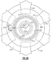
- the retaining ring 234 includes a ring body 237 that extends circumferentially about the disk axis D between first and second ring ends 235a, 235b.
- the retaining ring 234 can be constructed of materials such as high temperature metal alloys.
- An inner circumference 234b of the retaining ring 234 defines a ring length.
- the ring ends 235a, 235b are spaced apart in a decompressed state to define a circumferential gap 239 ( Figures 3B-3C ).
- the gap 239 is small relative to the ring length of the retaining ring.
- the retaining ring 234 includes outer and inner retaining features 241, 245 that continue along at least a portion of outer and inner circumferential faces 281, 282 of the retaining ring 234 to define a first circumferential length and a second circumferential length, respectively.
- the airfoil disk 218 includes an arm 251 that extends axially from face 219 of the airfoil disk 218 and a radially extending portion 251a to define a circumferentially extending ridge 255.
- the ridge 255 is dimensioned to receive at least a portion of the retaining ring 234.
- the arm 251 may be integrated with the airfoil disk 218 or may be a separate component attached to the airfoil disk 218.
- the retaining ring 234 is dimensioned to be disposed at least partially in the circumferentially extending ridge 255 to abut the coverplate 229.
- the outer retaining feature 241 is dimensioned to sit on the radially extending portion 251a of the arm 251.
- An inner circumference 295 of the coverplate 229 is dimensioned to sit on the inner retaining feature 245.
- An inner radial face 241c of the outer retaining feature 241 abuts an outer face 251b radial extending portion 251a, and an outer radial face 245c of the inner retaining feature 245 abuts an inner edge 284 of the coverplate 229.
- the retaining ring 234 can be tightly confined between the inner edge 284 of the coverplate 229 and the radial extending portion 251 a to limit radial movement of the coverplate.
- a thickness of the ring body 237 of the retention ring 234 is dimensioned to limit axial movement of the coverplate 229 relative to the airfoil disk 218 such that the airfoils 214 are secured in the slots 227 by having a forward face 229a of the coverplate 229 in contact with the inner circumferential face 282 of the retaining ring 234 and the outer circumferential face of the retaining ring 281 in contact with the radially extending portion 251a of the arm 251.
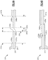
- Figures 4A-4B show a plan view of the retaining ring 234 in states of compression and decompression.
- Figure 4A shows the retaining ring 234 in a decompressed or relaxed state to define the circumferential gap 239.
- a length of the gap 239 in the relaxed state is less than 1% of the ring length.
- the length of the gap 239 in the relaxed state is between 0.2% and 0.4% of the ring length.
- a relatively small gap 239 can reduce stress concentrations in the coverplate 229 otherwise caused by a local lack of axial support by the retaining ring 234.
- Differential length 247a is defined between retaining end 245a and ring end 235a
- differential length 247b is defined between retaining end 245b and the ring end 235b
- differential length 247c is defined between retaining end 241b and ring end 235b
- differential length 247d is defined between retaining end 241a and ring end 235a.
- At least one of the retaining ends 241a/245a, 241b/245b is circumferentially spaced apart from the corresponding ring ends 234a, 235b.
- the differential lengths 247a, 247b are at least 1.5% of the ring length of the retaining ring 234. In another embodiment, the differential lengths are between 5% and 10% of the ring length.
- differential lengths 247a, 247b, 247c, and 247d are of equal lengths.
- differential lengths 247a, 247b, 247c, and 247d of varying lengths also come within the scope of the disclosure.
- Figure 4B shows the retaining ring 234 in a compressed state.
- the ring ends 235a, 235b circumferentially overlap such that the gap 239 is closed.
- Ring end 235a abuts retaining end 241b/245b and ring end 235b abuts the retaining end 241a/245a to limit circumferential movement of the ring ends 235a, 235b about disk axis D.
- the retaining ends 241a, 241b, 245a, 245b can be defined relative to the ring body 237 to limit a desired amount of compression of the retaining ring 234, while providing a relatively small gap 229 when decompressed.
- Figure 5 illustrates a method 264 of installation of a retention assembly, such as the retention assembly 260 of Figures 3A-3D , according to an embodiment.
- a retention assembly such as the retention assembly 260 of Figures 3A-3D
- one or more airfoil disks 218 are provided.
- one or more airfoils 214 are inserted into corresponding slots 227 defined by the airfoil disk 218.
- the retaining ring 234 is moved toward the airfoil disk 218 and is situated between the circumferentially extending ridge 255 and the disk face 219. The retaining ring 234 is compressed about the arm 251.
- the coverplate 229 is moved towards the disk 218 adjacent to the slots 227 and into abutment with the radial face 219 of the airfoil disk 218.
- the retaining ring 234 is released and expands or decompresses to urge the coverplate 229 against the face 219.
- the inner radial retaining feature 245 moves outwardly to abut the inner edge 284 of the coverplate 229, and outer radial retaining feature 241 moves into abutment with radially extending portion 251a.
Landscapes
- Engineering & Computer Science (AREA)
- Mechanical Engineering (AREA)
- General Engineering & Computer Science (AREA)
- Structures Of Non-Positive Displacement Pumps (AREA)
Abstract
Description
- This application relates generally to retention of airfoils in a gas turbine engine.
- A gas turbine engine typically includes a fan section, a compressor section, a combustor section and a turbine section. Air entering the compressor section is compressed and delivered into the combustion section where it is mixed with fuel and ignited to generate a high-speed exhaust gas flow. The high-speed exhaust gas flow expands through the turbine section to drive the compressor and the fan section. The compressor section typically includes low and high pressure compressors, and the turbine section includes low and high pressure turbines. The compressor and turbine sections can include one or more airfoil disks configured to carry an array of airfoils to compress or extract energy from the gas flow.
- An airfoil retention assembly for a gas turbine engine according to an example of the present disclosure includes a disk defining a disk axis and an array of slots configured to receive an array of blades, a coverplate dimensioned to radially overlap the array of slots relative to the disk axis, and a retaining ring that has a ring body extending circumferentially about the disk axis between first and second ring ends to define a ring length. A first retaining feature continues along a first circumferential face of the ring body to define a first length, and a second retaining feature continues along a second circumferential face of the ring body to define a second length. At least one of the first length and second length is less than the ring length.
- In a further embodiment of any of the foregoing embodiments, a difference between the ring length and the first length is at least 1.5% of the ring length.
- In a further embodiment of any of the foregoing embodiments, the retaining ring is configured such that the first ring end abuts first and second retaining ends of the first retaining feature in a compressed state.
- In a further embodiment of any of the foregoing embodiments, the first and second ring ends define a circumferential gap in an uncompressed state. The circumferential gap is less than 1% of the ring length.
- In a further embodiment of any of the foregoing embodiments, the circumferential gap is between 0.2% and 0.4% of the ring length in the uncompressed state.
- In a further embodiment of any of the foregoing embodiments, the first retaining feature and the second retaining feature are configured to limit radial movement of the coverplate relative to the disk axis.
- In a further embodiment of any of the foregoing embodiments, the coverplate is dimensioned to abut a radially extending face of the disk.
- In a further embodiment of any of the foregoing embodiments, both the first length and the second length are less than the ring length.
- In a further embodiment of any of the foregoing embodiments, the disk includes a disk arm that defines a circumferentially extending ridge dimensioned to receive at least a portion of the retaining ring.
- A gas turbine engine according to an example of the present disclosure includes a compressor section that has a first compressor and a second compressor, a turbine section configured to drive the compressor section, and a retention assembly that has a disk defining a disk axis and including an array of slots configured to receive an array of blades, a coverplate configured to abut the array of blades adjacent to the array of slots, and a retaining ring that has a ring body extending circumferentially between first and second ring ends to define a ring length. A first retaining feature extends circumferentially between a first retaining end and a second retaining end. At least one of the first and second retaining ends are circumferentially spaced apart from the first and second ring ends.
- In a further embodiment of any of the foregoing embodiments, a first differential length is defined between the first ring end and the first retaining end. A second differential length is defined between the second ring end and the second retaining end. The first differential length and the second differential length is at least 1.5% of the ring length.
- In a further embodiment of any of the foregoing embodiments, the retaining ring is configured such that the first ring end abuts the first retaining end in a compressed state, but is spaced apart from the first retaining end in an uncompressed state.
- In a further embodiment of any of the foregoing embodiments, the retention assembly is a plurality of retention assemblies each defining a corresponding turbine stage.
- In a further embodiment of any of the foregoing embodiments, the disk includes a disk arm and a circumferentially extending ridge dimensioned to receive at least a portion of the retaining ring.
- In a further embodiment of any of the foregoing embodiments, the retaining ring includes a second retaining feature extending circumferentially between a third retaining end and a fourth retaining end, the second retaining feature dimensioned to abut a radially extending portion of the disk arm.
- In a further embodiment of any of the foregoing embodiments, the first retaining feature and the second retaining feature are configured to limit radial movement of the coverplate relative to the disk axis.
- A method of retaining an airfoil in a gas turbine engine according to an example of the present disclosure includes providing a disk defining a disk axis, and having a radially extending disk face. A disk arm defines a circumferentially extending ridge, and an array of slots configured to receive an array of blades, moving at least one blade of the array of blades into one slot of the array of slots, moving a coverplate along the disk axis to abut the disk face, and situating a retaining ring at least partially in the circumferentially extending ridge the retaining ring including a ring body extending circumferentially about the disk axis between first and second ring ends to define a ring length. A first retaining feature continues along a first circumferential face of the retaining ring to define a first length. The first length is less than the ring length.
- A further embodiment of any of the foregoing embodiments includes compressing the retaining ring around the disk arm such that the first ring end abuts an end of the first retaining feature, and decompressing the retaining ring such that the retaining ring limits axial movement of the coverplate along the disk axis.
- In a further embodiment of any of the foregoing embodiments, the step of decompressing includes defining a circumferential gap between the first and second ring ends, the circumferential gap being less than 1% of the ring length.
- In a further embodiment of any of the foregoing embodiments, the retaining ring includes a second retaining feature continuing along a second circumferential face of the retaining ring. The first retaining feature is dimensioned to abut an inner edge of the coverplate and the second retaining feature is dimensioned to abut a radially extending portion of the disk arm.
-
-
Figure 1 schematically shows an embodiment of a gas turbine engine. -
Figure 2 schematically shows another embodiment of a gas turbine engine. -
Figure 3A schematically shows a turbine section of a gas turbine engine. -
Figure 3B schematically shows an axial view of an airfoil retention assembly alongline 3B-3B ofFigure 3A . -
Figure 3C is an isolated perspective view of portions of a retaining ring. -
Figure 3D shows a cross section view of the airfoil retention assembly offigure 3A . -
Figure 4A schematically shows the retaining ring ofFigure 3C in a relaxed state. -
Figure 4B schematically shows the retaining ring ofFigure 3C in a compressed state. -
Figure 5 is flowchart for installing a retention assembly. -
Figure 1 schematically illustrates agas turbine engine 20 for use in a commercial aircraft, for example. Thegas turbine engine 20 is disclosed herein as a two-spool turbofan that generally incorporates afan section 22, acompressor section 24, acombustor section 26 and aturbine section 28. Alternative engines might include an augmenter section (not shown) among other systems or features. Thefan section 22 drives air along a bypass flow path B in a bypass duct defined within anacelle 15, while thecompressor section 24 drives air along a core flow path C for compression and communication into thecombustor section 26 then expansion through theturbine section 28. Although depicted as a two-spool turbofan gas turbine engine in the disclosed non-limiting embodiment, it should be understood that the concepts described herein are not limited to use with two-spool turbofans as the teachings may be applied to other types of turbine engines including three-spool architectures. - The
exemplary engine 20 generally includes alow speed spool 30 and ahigh speed spool 32 mounted for rotation about an engine central longitudinal axis X relative to an enginestatic structure 36 viaseveral bearing systems 38. It should be understood thatvarious bearing systems 38 at various locations may alternatively or additionally be provided, and the location ofbearing systems 38 may be varied as appropriate to the application. - The
low speed spool 30 generally includes aninner shaft 40 that interconnects afan 42, a first (or low)pressure compressor 44 and a first (or low)pressure turbine 46. Theinner shaft 40 is connected to thefan 42 through a speed change mechanism, which in exemplarygas turbine engine 20 is illustrated as a gearedarchitecture 48 to drive thefan 42 at a lower speed than thelow speed spool 30. Thehigh speed spool 32 includes anouter shaft 50 that interconnects a second (or high)pressure compressor 52 and a second (or high)pressure turbine 54. Acombustor 56 is arranged inexemplary gas turbine 20 between thehigh pressure compressor 52 and thehigh pressure turbine 54. Amid-turbine frame 57 of the enginestatic structure 36 is arranged generally between thehigh pressure turbine 54 and thelow pressure turbine 46. Themid-turbine frame 57 further supports bearingsystems 38 in theturbine section 28. Theinner shaft 40 and theouter shaft 50 are concentric and rotate viabearing systems 38 about the engine central longitudinal axis X which is collinear with their longitudinal axes. - The core airflow is compressed by the
low pressure compressor 44 then thehigh pressure compressor 52, mixed and burned with fuel in thecombustor 56, then expanded over thehigh pressure turbine 54 andlow pressure turbine 46. Themid-turbine frame 57 includesairfoils 59 which are in the core airflow path C. Theturbines low speed spool 30 andhigh speed spool 32 in response to the expansion. It will be appreciated that each of the positions of thefan section 22,compressor section 24,combustor section 26,turbine section 28, and fandrive gear system 48 may be varied. For example,gear system 48 may be located aft ofcombustor section 26 or even aft ofturbine section 28, andfan section 22 may be positioned forward or aft of the location ofgear system 48. - The
engine 20 in one example is a high-bypass geared aircraft engine. In a further example, theengine 20 bypass ratio is greater than about six (6), with an example embodiment being greater than about ten (10), the gearedarchitecture 48 is an epicyclic gear train, such as a planetary gear system or other gear system, with a gear reduction ratio of greater than about 2.3 and thelow pressure turbine 46 has a pressure ratio that is greater than about five. In one disclosed embodiment, theengine 20 bypass ratio is greater than about ten (10:1), the fan diameter is significantly larger than that of thelow pressure compressor 44, and thelow pressure turbine 46 has a pressure ratio that is greater than about five 5:1.Low pressure turbine 46 pressure ratio is pressure measured prior to inlet oflow pressure turbine 46 as related to the pressure at the outlet of thelow pressure turbine 46 prior to an exhaust nozzle. The gearedarchitecture 48 may be an epicycle gear train, such as a planetary gear system or other gear system, with a gear reduction ratio of greater than about 2.3:1. It should be understood, however, that the above parameters are only exemplary of one embodiment of a geared architecture engine and that the present invention is applicable to other gas turbine engines including direct drive turbofans. - A significant amount of thrust is provided by the bypass flow B due to the high bypass ratio. The
fan section 22 of theengine 20 is designed for a particular flight condition -- typically cruise at about 0.8 Mach and about 35,000 feet (10,668 meters). The flight condition of 0.8 Mach and 35,000 ft (10,668 meters), with the engine at its best fuel consumption - also known as "bucket cruise Thrust Specific Fuel Consumption ('TSFC')" - is the industry standard parameter of lbm of fuel being burned divided by lbf of thrust the engine produces at that minimum point. "Low fan pressure ratio" is the pressure ratio across the fan blade alone, without a Fan Exit Guide Vane ("FEGV") system. The low fan pressure ratio as disclosed herein according to one non-limiting embodiment is less than about 1.45. "Low corrected fan tip speed" is the actual fan tip speed in ft/sec divided by an industry standard temperature correction of [(Tram °R) / (518.7 °R)]0.5 (where °R = K x 9/5). The "Low corrected fan tip speed" as disclosed herein according to one non-limiting embodiment is less than about 1150 ft / second (350.5 meters/second). - Referring to
Figure 2 , agas turbine engine 120 according to a second embodiment is disclosed.Engine 120 may be used in a military application, for example, and includes afan section 122, acompressor section 124, acombustor section 126, and aturbine section 128. Air entering into thefan section 122 is initially compressed and fed to thecompressor section 124. In thecompressor section 124, the incoming air from thefan section 122 is further compressed and communicated to thecombustor section 126. In thecombustor section 126, the compressed air is mixed with gas and ignited to generate ahot exhaust stream 131. Thehot exhaust stream 131 is expanded through theturbine section 128 to drive thefan section 122 and thecompressor section 124. In this example, thegas turbine engine 120 includes anaugmenter section 130 where additional fuel can be mixed with theexhaust gasses 131 and ignited to generate additional thrust. Theexhaust gasses 131 flow from theturbine section 128 and theaugmenter section 130 through anexhaust liner assembly 133. -
Figures 3A-3D show anairfoil retention assembly 260 in aturbine section 228. In this disclosure, like reference numerals designate like elements where appropriate and reference numerals with the addition of one-hundred or multiples thereof designate modified elements that are understood to incorporate the same features and benefits of the corresponding original elements. Although theretention assembly 260 is primarily discussed relative toturbine section 228, other portions ofengine 20/120 may benefit from the teachings herein, includingcompressor section 24/124. -
Turbine section 228 includes rows of airfoils, includingstationary vanes 286 androtating airfoils 214. Each defining a stage of theturbine section 228. Theairfoils 214 each have anairfoil body 215 that extends from anairfoil root 223. A blade outer air seal (BOAS) 288 is spaced radially outward from atip 290 of theairfoil 214. Avane 286 is positioned along the engine axis X and adjacent to theairfoil 214. Theturbine section 228 includesmultiple airfoils 214,vanes 286, andBOAS 288 arranged circumferentially about the engine axis X. - Each
retention assembly 260 includes anairfoil disk 218, acoverplate 229, and aretention ring 234. Theturbine section 228 schematically represented inFigure 3A includes one ormore airfoil disks 218 arranged along engine axis X. Eachairfoil disk 218 defines one ormore slots 227 to carry one ormore airfoils 214. Theairfoil roots 223 are retained in correspondingslots 227, which may be dimensioned to limit relative radial and circumferential movement. Theslots 227 can be uniformly distributed about a circumference of theairfoil disk 218. - In the illustrated embodiment of
Figure 3A , the turbine section includes a plurality ofretention assemblies 260. In one embodiment, eachairfoil disk 218 defines a corresponding turbine stage. In the illustrated example,coverplate 229 andretention ring 234 are situated adjacent to anairfoil face 219. Aft coverplate 229' and retention ring 234' are situated adjacent to aft face 219' of thedisk 218 to limit axial movement of theairfoils 214 relative to a disk axis D. The disk axis D can be coaxially aligned with the engine axis X. - The
coverplate 229 is dimensioned to radiallyoverlap slots 227 such that theairfoil roots 223 are retained axially in theslots 227. Thecoverplate 229 is in turn retained by retainingring 234. In the illustrated embodiment, thecoverplate 229 and retainingring 234 are generally annular, and both extend circumferentially about the disk axis D. Thecoverplate 229 abuts aforward face 219 of theairfoil disk 218. The aft coverplate 229' abuts an aft face 219' of theairfoil disk 218. - Referring to
figures 3B-3C , with continuing reference toFigure 3A , the retainingring 234 includes aring body 237 that extends circumferentially about the disk axis D between first and second ring ends 235a, 235b. The retainingring 234 can be constructed of materials such as high temperature metal alloys. Aninner circumference 234b of the retainingring 234 defines a ring length. The ring ends 235a, 235b are spaced apart in a decompressed state to define a circumferential gap 239 (Figures 3B-3C ). Thegap 239 is small relative to the ring length of the retaining ring. The retainingring 234 includes outer and inner retaining features 241, 245 that continue along at least a portion of outer and inner circumferential faces 281, 282 of the retainingring 234 to define a first circumferential length and a second circumferential length, respectively. - Referring to
Figure 3D , with continuing reference toFigures 3A-3C , theairfoil disk 218 includes anarm 251 that extends axially fromface 219 of theairfoil disk 218 and aradially extending portion 251a to define acircumferentially extending ridge 255. Theridge 255 is dimensioned to receive at least a portion of the retainingring 234. Thearm 251 may be integrated with theairfoil disk 218 or may be a separate component attached to theairfoil disk 218. The retainingring 234 is dimensioned to be disposed at least partially in thecircumferentially extending ridge 255 to abut thecoverplate 229. Theouter retaining feature 241 is dimensioned to sit on theradially extending portion 251a of thearm 251. Aninner circumference 295 of thecoverplate 229 is dimensioned to sit on theinner retaining feature 245. An innerradial face 241c of theouter retaining feature 241 abuts anouter face 251bradial extending portion 251a, and an outerradial face 245c of theinner retaining feature 245 abuts aninner edge 284 of thecoverplate 229. The retainingring 234 can be tightly confined between theinner edge 284 of thecoverplate 229 and theradial extending portion 251 a to limit radial movement of the coverplate. A thickness of thering body 237 of theretention ring 234 is dimensioned to limit axial movement of thecoverplate 229 relative to theairfoil disk 218 such that theairfoils 214 are secured in theslots 227 by having aforward face 229a of thecoverplate 229 in contact with the innercircumferential face 282 of the retainingring 234 and the outer circumferential face of the retainingring 281 in contact with theradially extending portion 251a of thearm 251. -
Figures 4A-4B show a plan view of the retainingring 234 in states of compression and decompression.Figure 4A shows the retainingring 234 in a decompressed or relaxed state to define thecircumferential gap 239. In an embodiment, a length of thegap 239 in the relaxed state is less than 1% of the ring length. In another embodiment, the length of thegap 239 in the relaxed state is between 0.2% and 0.4% of the ring length. A relativelysmall gap 239 can reduce stress concentrations in thecoverplate 229 otherwise caused by a local lack of axial support by the retainingring 234. - Differential length 247a is defined between retaining
end 245a andring end 235a,differential length 247b is defined between retainingend 245b and thering end 235b,differential length 247c is defined between retainingend 241b andring end 235b, anddifferential length 247d is defined between retainingend 241a andring end 235a. At least one of the retaining ends 241a/245a, 241b/245b is circumferentially spaced apart from the corresponding ring ends 234a, 235b. In an embodiment, thedifferential lengths 247a, 247b are at least 1.5% of the ring length of the retainingring 234. In another embodiment, the differential lengths are between 5% and 10% of the ring length. In the illustrated embodiment,differential lengths differential lengths -
Figure 4B shows the retainingring 234 in a compressed state. In the compressed state, the ring ends 235a, 235b circumferentially overlap such that thegap 239 is closed.Ring end 235a abuts retainingend 241b/245b andring end 235b abuts the retainingend 241a/245a to limit circumferential movement of the ring ends 235a, 235b about disk axis D. The retaining ends 241a, 241b, 245a, 245b can be defined relative to thering body 237 to limit a desired amount of compression of the retainingring 234, while providing a relativelysmall gap 229 when decompressed. -
Figure 5 illustrates amethod 264 of installation of a retention assembly, such as theretention assembly 260 ofFigures 3A-3D , according to an embodiment. Atstep 266, one ormore airfoil disks 218 are provided. Atstep 268, one ormore airfoils 214 are inserted into correspondingslots 227 defined by theairfoil disk 218. Atstep 270, the retainingring 234 is moved toward theairfoil disk 218 and is situated between thecircumferentially extending ridge 255 and thedisk face 219. The retainingring 234 is compressed about thearm 251. Atstep 272 thecoverplate 229 is moved towards thedisk 218 adjacent to theslots 227 and into abutment with theradial face 219 of theairfoil disk 218. Atstep 274, the retainingring 234 is released and expands or decompresses to urge thecoverplate 229 against theface 219. During decompression, the innerradial retaining feature 245 moves outwardly to abut theinner edge 284 of thecoverplate 229, and outerradial retaining feature 241 moves into abutment with radially extendingportion 251a. - Although the different examples have a specific component shown in the illustrations, embodiments of this disclosure are not limited to those particular combinations. It is possible to use some of the components or features from one of the examples in combination with features or components from another one of the examples. Also, although particular step sequences are shown, described, and claimed, it should be understood that steps may be performed in any order, separated or combined unless otherwise indicated and will still benefit from the present disclosure.
- Although an example embodiment has been disclosed, a worker of ordinary skill in this art would recognize that certain modifications would come within the scope of this disclosure. For that reason, the following claims should be studied to determine the scope and content of this disclosure.
Claims (15)
- An airfoil retention assembly (260) for a gas turbine engine (20;120) comprising:a disk (218) defining a disk axis (D) and an array of slots (227) configured to receive an array of blades (214);a coverplate (229) dimensioned to radially overlap the array of slots (227) relative to the disk axis (D); anda retaining ring (234) including a ring body (237) extending circumferentially about the disk axis (D) between first and second ring ends (235a,b) to define a ring length, a first retaining feature (241) continuing along a first circumferential face (281) of the ring body (237) to define a first length, and a second retaining feature (245) continuing along a second circumferential face (282) of the ring body (237) to define a second length, wherein at least one of the first length and second length being less than the ring length.
- The airfoil retention assembly of claim 1, wherein a difference between the ring length and the first length is at least 1.5% of the ring length.
- The airfoil retention assembly of claim 1 or 2, wherein the retaining ring (234) is configured such that the first ring end (235a) abuts first and second retaining ends (241a,b) of the first retaining feature (241) in a compressed state.
- The airfoil retention assembly of any preceding claim, wherein the first and second ring ends (235a,b) define a circumferential gap (239) in an uncompressed state, the circumferential gap (239) being less than 1% of the ring length, for example between 0.2% and 0.4% of the ring length in the uncompressed state.
- The airfoil retention assembly of any preceding claim, wherein the first retaining feature (241) and the second retaining feature (245) are configured to limit radial movement of the coverplate (229) relative to the disk axis (D), wherein, optionally, the coverplate (229) is dimensioned to abut a radially extending face (219) of the disk (218).
- The airfoil retention assembly of any preceding claim, wherein both the first length and the second length are less than the ring length.
- The airfoil retention assembly of any preceding claim, wherein the disk (218) includes a disk arm (251) that defines a circumferentially extending ridge (255) dimensioned to receive at least a portion of the retaining ring (234).
- A gas turbine engine (20; 120), comprising:a compressor section (24;124), including a first compressor (44) and a second compressor (52);a turbine section (28;128;228) configured to drive the compressor section (24; 124); anda retention assembly (260), comprising:a disk (218) defining a disk axis (D) and including an array of slots (227) configured to receive an array of blades (214);a coverplate (229) configured to abut the array of blades (214) adjacent to the array of slots (227); anda retaining ring (234) including a ring body (237) extending circumferentially between first and second ring ends (235a,b) to define a ring length, a first retaining feature (241) extending circumferentially between a first retaining end (241b) and a second retaining end (241a), at least one of the first and second retaining ends (241b,a) being circumferentially spaced apart from the first and second ring ends (235a,b).
- The gas turbine engine of claim 8, wherein:a first differential length (247d) is defined between the first ring end (235a) and the first retaining end (241b);a second differential length (247c) is defined between the second ring end (235b) and the second retaining end (241a); andthe first differential length (247d) and the second differential length (247c) is at least 1.5% of the ring length.
- The gas turbine engine of claim 8 or 9, wherein the retaining ring (234) is configured such that the first ring end (235a) abuts the first retaining end (241b) in a compressed state, but is spaced apart from the first retaining end (241b) in an uncompressed state.
- The gas turbine engine of claim 8, 9 or 10, wherein the retention assembly (260) is a plurality of retention assemblies (260) each defining a corresponding turbine stage.
- The gas turbine engine of any of claims 8 to 11, wherein the disk (218) includes a disk arm (251) and a circumferentially extending ridge (255) dimensioned to receive at least a portion of the retaining ring (234), wherein, optionally, the retaining ring (234) includes a second retaining feature (245) extending circumferentially between a third retaining end (245a) and a fourth retaining end (245b), the second retaining feature (245) dimensioned to abut a radially extending portion of the disk arm (251), wherein, further optionally, the first retaining feature (241) and the second retaining feature (245) are configured to limit radial movement of the coverplate (229) relative to the disk axis (D).
- A method of retaining an airfoil in a gas turbine engine (20; 120), comprising:providing a disk (218) defining a disk axis (D), and having a radially extending disk face (219), a disk arm (251) defining a circumferentially extending ridge (255), and an array of slots (227) configured to receive an array of blades (214);moving at least one blade (214) of the array of blades (214) into one slot (227) of the array of slots (227);moving a coverplate (229) along the disk axis (D) to abut the disk face (219); andsituating a retaining ring (234) at least partially in the circumferentially extending ridge (255) the retaining ring (234) including a ring body (237) extending circumferentially about the disk axis (D) between first and second ring ends (235b,a) to define a ring length, a first retaining feature (245) continuing along a first circumferential face (282) of the retaining ring (234) to define a first length, wherein the first length is less than the ring length.
- The method of claim 13, further comprising:compressing the retaining ring (234) around the disk arm (251) such that the first ring end (235b) abuts an end (245a) of the first retaining feature (245); anddecompressing the retaining ring (234) such that the retaining ring (234) limits axial movement of the coverplate (229) along the disk axis (D),wherein, optionally, the step of decompressing includes defining a circumferential gap (239) between the first and second ring ends (235a,b), the circumferential gap (239) being less than 1% of the ring length.
- The method of claim 13 or 14, wherein the retaining ring (234) includes a second retaining feature (241) continuing along a second circumferential face (281) of the retaining ring (234), the first retaining feature (245) is dimensioned to abut an inner edge (284) of the coverplate (229) and the second retaining feature (241) is dimensioned to abut a radially extending portion (251a) of the disk arm (251).
Applications Claiming Priority (1)
| Application Number | Priority Date | Filing Date | Title |
|---|---|---|---|
| US15/259,641 US10415401B2 (en) | 2016-09-08 | 2016-09-08 | Airfoil retention assembly for a gas turbine engine |
Publications (2)
| Publication Number | Publication Date |
|---|---|
| EP3293358A1 true EP3293358A1 (en) | 2018-03-14 |
| EP3293358B1 EP3293358B1 (en) | 2020-04-08 |
Family
ID=59799321
Family Applications (1)
| Application Number | Title | Priority Date | Filing Date |
|---|---|---|---|
| EP17189637.6A Active EP3293358B1 (en) | 2016-09-08 | 2017-09-06 | Airfoil retention assembly for a gas turbine engine |
Country Status (2)
| Country | Link |
|---|---|
| US (1) | US10415401B2 (en) |
| EP (1) | EP3293358B1 (en) |
Cited By (1)
| Publication number | Priority date | Publication date | Assignee | Title |
|---|---|---|---|---|
| EP3473810B1 (en) * | 2017-10-18 | 2020-12-16 | United Technologies Corporation | Tuned retention ring for rotor disk |
Families Citing this family (3)
| Publication number | Priority date | Publication date | Assignee | Title |
|---|---|---|---|---|
| US10215037B2 (en) * | 2016-05-13 | 2019-02-26 | United Technologies Corporation | Contoured retaining ring |
| GB2584097A (en) * | 2019-05-20 | 2020-11-25 | Cross Mfg 1938 Limited | Ring fastener |
| DE102022134909A1 (en) * | 2022-12-28 | 2024-07-04 | Rolls-Royce Deutschland Ltd & Co Kg | Assembly for a gas turbine engine and method for attaching a blade retaining plate to a rotor disk of a gas turbine engine |
Citations (4)
| Publication number | Priority date | Publication date | Assignee | Title |
|---|---|---|---|---|
| US4304523A (en) * | 1980-06-23 | 1981-12-08 | General Electric Company | Means and method for securing a member to a structure |
| US5302086A (en) * | 1992-08-18 | 1994-04-12 | General Electric Company | Apparatus for retaining rotor blades |
| GB2410984A (en) * | 2004-02-14 | 2005-08-17 | Rolls Royce Plc | Securing arrangement, eg for the seal plate of a gas turbine engine |
| EP2439378A2 (en) * | 2010-10-06 | 2012-04-11 | General Electric Company | Turbine bucket lockwire rotation prevention |
Family Cites Families (11)
| Publication number | Priority date | Publication date | Assignee | Title |
|---|---|---|---|---|
| US5211407A (en) * | 1992-04-30 | 1993-05-18 | General Electric Company | Compressor rotor cross shank leak seal for axial dovetails |
| US5281098A (en) | 1992-10-28 | 1994-01-25 | General Electric Company | Single ring blade retaining assembly |
| US5338154A (en) * | 1993-03-17 | 1994-08-16 | General Electric Company | Turbine disk interstage seal axial retaining ring |
| US5993160A (en) | 1997-12-11 | 1999-11-30 | Pratt & Whitney Canada Inc. | Cover plate for gas turbine rotor |
| US6234756B1 (en) | 1998-10-26 | 2001-05-22 | Allison Advanced Development Company | Segmented ring blade retainer |
| US6951448B2 (en) | 2002-04-16 | 2005-10-04 | United Technologies Corporation | Axial retention system and components thereof for a bladed rotor |
| FR2918106B1 (en) | 2007-06-27 | 2011-05-06 | Snecma | AXIS RETAINING DEVICE OF AUBES MOUNTED ON A TURBOMACHINE ROTOR DISC. |
| US8727735B2 (en) | 2011-06-30 | 2014-05-20 | General Electric Company | Rotor assembly and reversible turbine blade retainer therefor |
| US8979502B2 (en) | 2011-12-15 | 2015-03-17 | Pratt & Whitney Canada Corp. | Turbine rotor retaining system |
| US9399926B2 (en) * | 2013-08-23 | 2016-07-26 | Siemens Energy, Inc. | Belly band seal with circumferential spacer |
| US9677427B2 (en) | 2014-07-04 | 2017-06-13 | Pratt & Whitney Canada Corp. | Axial retaining ring for turbine vanes |
-
2016
- 2016-09-08 US US15/259,641 patent/US10415401B2/en active Active
-
2017
- 2017-09-06 EP EP17189637.6A patent/EP3293358B1/en active Active
Patent Citations (4)
| Publication number | Priority date | Publication date | Assignee | Title |
|---|---|---|---|---|
| US4304523A (en) * | 1980-06-23 | 1981-12-08 | General Electric Company | Means and method for securing a member to a structure |
| US5302086A (en) * | 1992-08-18 | 1994-04-12 | General Electric Company | Apparatus for retaining rotor blades |
| GB2410984A (en) * | 2004-02-14 | 2005-08-17 | Rolls Royce Plc | Securing arrangement, eg for the seal plate of a gas turbine engine |
| EP2439378A2 (en) * | 2010-10-06 | 2012-04-11 | General Electric Company | Turbine bucket lockwire rotation prevention |
Cited By (1)
| Publication number | Priority date | Publication date | Assignee | Title |
|---|---|---|---|---|
| EP3473810B1 (en) * | 2017-10-18 | 2020-12-16 | United Technologies Corporation | Tuned retention ring for rotor disk |
Also Published As
| Publication number | Publication date |
|---|---|
| US10415401B2 (en) | 2019-09-17 |
| EP3293358B1 (en) | 2020-04-08 |
| US20180066529A1 (en) | 2018-03-08 |
Similar Documents
| Publication | Publication Date | Title |
|---|---|---|
| US10633994B2 (en) | Feather seal assembly | |
| US10890079B2 (en) | Gas turbine engine arc segments with arced walls | |
| EP3039252B1 (en) | Variable vane bushing | |
| EP3064711A1 (en) | Component, corresponding gas turbine engine and method | |
| EP3112591B1 (en) | Tip shrouded high aspect ratio compressor stage | |
| US20190195088A1 (en) | Flexible preloaded ball bearing assembly | |
| US10458265B2 (en) | Integrally bladed rotor | |
| EP3587740A1 (en) | Gas turbine engine component | |
| EP2998522B1 (en) | Gas turbine engine variable stator vane | |
| EP3293358B1 (en) | Airfoil retention assembly for a gas turbine engine | |
| EP2985419B1 (en) | Turbomachine blade assembly with blade root seals | |
| EP2985421A1 (en) | Assembly, compressor and cooling system | |
| EP3498978B1 (en) | Gas turbine engine vane with attachment hook | |
| EP3012411B1 (en) | Integrally bladed rotor having axial arm and pocket | |
| US9890641B2 (en) | Gas turbine engine truncated airfoil fillet | |
| EP3564495A1 (en) | Gas turbine engine exhaust component | |
| US20160215642A1 (en) | Plug seal for gas turbine engine | |
| US11199104B2 (en) | Seal anti-rotation | |
| EP3228856B1 (en) | Fan blade removal feature for a gas turbine engine and associated method | |
| US20140161616A1 (en) | Multi-piece blade for gas turbine engine | |
| US20240151152A1 (en) | Seal for gas turbine engine | |
| US9341070B2 (en) | Shield slot on side of load slot in gas turbine engine rotor | |
| EP3045658B1 (en) | Gas turbine engine rotor | |
| EP3550105B1 (en) | Gas turbine engine rotor disk | |
| WO2015020715A2 (en) | Gas turbine hub |
Legal Events
| Date | Code | Title | Description |
|---|---|---|---|
| PUAI | Public reference made under article 153(3) epc to a published international application that has entered the european phase |
Free format text: ORIGINAL CODE: 0009012 |
|
| STAA | Information on the status of an ep patent application or granted ep patent |
Free format text: STATUS: THE APPLICATION HAS BEEN PUBLISHED |
|
| AK | Designated contracting states |
Kind code of ref document: A1 Designated state(s): AL AT BE BG CH CY CZ DE DK EE ES FI FR GB GR HR HU IE IS IT LI LT LU LV MC MK MT NL NO PL PT RO RS SE SI SK SM TR |
|
| AX | Request for extension of the european patent |
Extension state: BA ME |
|
| STAA | Information on the status of an ep patent application or granted ep patent |
Free format text: STATUS: REQUEST FOR EXAMINATION WAS MADE |
|
| 17P | Request for examination filed |
Effective date: 20180904 |
|
| RBV | Designated contracting states (corrected) |
Designated state(s): AL AT BE BG CH CY CZ DE DK EE ES FI FR GB GR HR HU IE IS IT LI LT LU LV MC MK MT NL NO PL PT RO RS SE SI SK SM TR |
|
| GRAP | Despatch of communication of intention to grant a patent |
Free format text: ORIGINAL CODE: EPIDOSNIGR1 |
|
| STAA | Information on the status of an ep patent application or granted ep patent |
Free format text: STATUS: GRANT OF PATENT IS INTENDED |
|
| INTG | Intention to grant announced |
Effective date: 20191111 |
|
| GRAS | Grant fee paid |
Free format text: ORIGINAL CODE: EPIDOSNIGR3 |
|
| GRAA | (expected) grant |
Free format text: ORIGINAL CODE: 0009210 |
|
| STAA | Information on the status of an ep patent application or granted ep patent |
Free format text: STATUS: THE PATENT HAS BEEN GRANTED |
|
| AK | Designated contracting states |
Kind code of ref document: B1 Designated state(s): AL AT BE BG CH CY CZ DE DK EE ES FI FR GB GR HR HU IE IS IT LI LT LU LV MC MK MT NL NO PL PT RO RS SE SI SK SM TR |
|
| REG | Reference to a national code |
Ref country code: CH Ref legal event code: EP Ref country code: AT Ref legal event code: REF Ref document number: 1254650 Country of ref document: AT Kind code of ref document: T Effective date: 20200415 |
|
| REG | Reference to a national code |
Ref country code: DE Ref legal event code: R096 Ref document number: 602017014270 Country of ref document: DE |
|
| REG | Reference to a national code |
Ref country code: IE Ref legal event code: FG4D |
|
| REG | Reference to a national code |
Ref country code: NL Ref legal event code: MP Effective date: 20200408 |
|
| REG | Reference to a national code |
Ref country code: LT Ref legal event code: MG4D |
|
| PG25 | Lapsed in a contracting state [announced via postgrant information from national office to epo] |
Ref country code: IS Free format text: LAPSE BECAUSE OF FAILURE TO SUBMIT A TRANSLATION OF THE DESCRIPTION OR TO PAY THE FEE WITHIN THE PRESCRIBED TIME-LIMIT Effective date: 20200808 Ref country code: PT Free format text: LAPSE BECAUSE OF FAILURE TO SUBMIT A TRANSLATION OF THE DESCRIPTION OR TO PAY THE FEE WITHIN THE PRESCRIBED TIME-LIMIT Effective date: 20200817 Ref country code: GR Free format text: LAPSE BECAUSE OF FAILURE TO SUBMIT A TRANSLATION OF THE DESCRIPTION OR TO PAY THE FEE WITHIN THE PRESCRIBED TIME-LIMIT Effective date: 20200709 Ref country code: NO Free format text: LAPSE BECAUSE OF FAILURE TO SUBMIT A TRANSLATION OF THE DESCRIPTION OR TO PAY THE FEE WITHIN THE PRESCRIBED TIME-LIMIT Effective date: 20200708 Ref country code: FI Free format text: LAPSE BECAUSE OF FAILURE TO SUBMIT A TRANSLATION OF THE DESCRIPTION OR TO PAY THE FEE WITHIN THE PRESCRIBED TIME-LIMIT Effective date: 20200408 Ref country code: NL Free format text: LAPSE BECAUSE OF FAILURE TO SUBMIT A TRANSLATION OF THE DESCRIPTION OR TO PAY THE FEE WITHIN THE PRESCRIBED TIME-LIMIT Effective date: 20200408 Ref country code: SE Free format text: LAPSE BECAUSE OF FAILURE TO SUBMIT A TRANSLATION OF THE DESCRIPTION OR TO PAY THE FEE WITHIN THE PRESCRIBED TIME-LIMIT Effective date: 20200408 Ref country code: LT Free format text: LAPSE BECAUSE OF FAILURE TO SUBMIT A TRANSLATION OF THE DESCRIPTION OR TO PAY THE FEE WITHIN THE PRESCRIBED TIME-LIMIT Effective date: 20200408 |
|
| REG | Reference to a national code |
Ref country code: AT Ref legal event code: MK05 Ref document number: 1254650 Country of ref document: AT Kind code of ref document: T Effective date: 20200408 |
|
| PG25 | Lapsed in a contracting state [announced via postgrant information from national office to epo] |
Ref country code: BG Free format text: LAPSE BECAUSE OF FAILURE TO SUBMIT A TRANSLATION OF THE DESCRIPTION OR TO PAY THE FEE WITHIN THE PRESCRIBED TIME-LIMIT Effective date: 20200708 Ref country code: RS Free format text: LAPSE BECAUSE OF FAILURE TO SUBMIT A TRANSLATION OF THE DESCRIPTION OR TO PAY THE FEE WITHIN THE PRESCRIBED TIME-LIMIT Effective date: 20200408 Ref country code: LV Free format text: LAPSE BECAUSE OF FAILURE TO SUBMIT A TRANSLATION OF THE DESCRIPTION OR TO PAY THE FEE WITHIN THE PRESCRIBED TIME-LIMIT Effective date: 20200408 Ref country code: HR Free format text: LAPSE BECAUSE OF FAILURE TO SUBMIT A TRANSLATION OF THE DESCRIPTION OR TO PAY THE FEE WITHIN THE PRESCRIBED TIME-LIMIT Effective date: 20200408 |
|
| PG25 | Lapsed in a contracting state [announced via postgrant information from national office to epo] |
Ref country code: AL Free format text: LAPSE BECAUSE OF FAILURE TO SUBMIT A TRANSLATION OF THE DESCRIPTION OR TO PAY THE FEE WITHIN THE PRESCRIBED TIME-LIMIT Effective date: 20200408 |
|
| REG | Reference to a national code |
Ref country code: DE Ref legal event code: R097 Ref document number: 602017014270 Country of ref document: DE |
|
| PG25 | Lapsed in a contracting state [announced via postgrant information from national office to epo] |
Ref country code: AT Free format text: LAPSE BECAUSE OF FAILURE TO SUBMIT A TRANSLATION OF THE DESCRIPTION OR TO PAY THE FEE WITHIN THE PRESCRIBED TIME-LIMIT Effective date: 20200408 Ref country code: DK Free format text: LAPSE BECAUSE OF FAILURE TO SUBMIT A TRANSLATION OF THE DESCRIPTION OR TO PAY THE FEE WITHIN THE PRESCRIBED TIME-LIMIT Effective date: 20200408 Ref country code: EE Free format text: LAPSE BECAUSE OF FAILURE TO SUBMIT A TRANSLATION OF THE DESCRIPTION OR TO PAY THE FEE WITHIN THE PRESCRIBED TIME-LIMIT Effective date: 20200408 Ref country code: SM Free format text: LAPSE BECAUSE OF FAILURE TO SUBMIT A TRANSLATION OF THE DESCRIPTION OR TO PAY THE FEE WITHIN THE PRESCRIBED TIME-LIMIT Effective date: 20200408 Ref country code: CZ Free format text: LAPSE BECAUSE OF FAILURE TO SUBMIT A TRANSLATION OF THE DESCRIPTION OR TO PAY THE FEE WITHIN THE PRESCRIBED TIME-LIMIT Effective date: 20200408 Ref country code: RO Free format text: LAPSE BECAUSE OF FAILURE TO SUBMIT A TRANSLATION OF THE DESCRIPTION OR TO PAY THE FEE WITHIN THE PRESCRIBED TIME-LIMIT Effective date: 20200408 Ref country code: IT Free format text: LAPSE BECAUSE OF FAILURE TO SUBMIT A TRANSLATION OF THE DESCRIPTION OR TO PAY THE FEE WITHIN THE PRESCRIBED TIME-LIMIT Effective date: 20200408 Ref country code: ES Free format text: LAPSE BECAUSE OF FAILURE TO SUBMIT A TRANSLATION OF THE DESCRIPTION OR TO PAY THE FEE WITHIN THE PRESCRIBED TIME-LIMIT Effective date: 20200408 |
|
| PLBE | No opposition filed within time limit |
Free format text: ORIGINAL CODE: 0009261 |
|
| STAA | Information on the status of an ep patent application or granted ep patent |
Free format text: STATUS: NO OPPOSITION FILED WITHIN TIME LIMIT |
|
| PG25 | Lapsed in a contracting state [announced via postgrant information from national office to epo] |
Ref country code: PL Free format text: LAPSE BECAUSE OF FAILURE TO SUBMIT A TRANSLATION OF THE DESCRIPTION OR TO PAY THE FEE WITHIN THE PRESCRIBED TIME-LIMIT Effective date: 20200408 Ref country code: SK Free format text: LAPSE BECAUSE OF FAILURE TO SUBMIT A TRANSLATION OF THE DESCRIPTION OR TO PAY THE FEE WITHIN THE PRESCRIBED TIME-LIMIT Effective date: 20200408 |
|
| 26N | No opposition filed |
Effective date: 20210112 |
|
| REG | Reference to a national code |
Ref country code: CH Ref legal event code: PL |
|
| PG25 | Lapsed in a contracting state [announced via postgrant information from national office to epo] |
Ref country code: SI Free format text: LAPSE BECAUSE OF FAILURE TO SUBMIT A TRANSLATION OF THE DESCRIPTION OR TO PAY THE FEE WITHIN THE PRESCRIBED TIME-LIMIT Effective date: 20200408 |
|
| REG | Reference to a national code |
Ref country code: BE Ref legal event code: MM Effective date: 20200930 |
|
| PG25 | Lapsed in a contracting state [announced via postgrant information from national office to epo] |
Ref country code: LU Free format text: LAPSE BECAUSE OF NON-PAYMENT OF DUE FEES Effective date: 20200906 |
|
| PG25 | Lapsed in a contracting state [announced via postgrant information from national office to epo] |
Ref country code: BE Free format text: LAPSE BECAUSE OF NON-PAYMENT OF DUE FEES Effective date: 20200930 Ref country code: CH Free format text: LAPSE BECAUSE OF NON-PAYMENT OF DUE FEES Effective date: 20200930 Ref country code: IE Free format text: LAPSE BECAUSE OF NON-PAYMENT OF DUE FEES Effective date: 20200906 Ref country code: LI Free format text: LAPSE BECAUSE OF NON-PAYMENT OF DUE FEES Effective date: 20200930 |
|
| PG25 | Lapsed in a contracting state [announced via postgrant information from national office to epo] |
Ref country code: TR Free format text: LAPSE BECAUSE OF FAILURE TO SUBMIT A TRANSLATION OF THE DESCRIPTION OR TO PAY THE FEE WITHIN THE PRESCRIBED TIME-LIMIT Effective date: 20200408 Ref country code: MT Free format text: LAPSE BECAUSE OF FAILURE TO SUBMIT A TRANSLATION OF THE DESCRIPTION OR TO PAY THE FEE WITHIN THE PRESCRIBED TIME-LIMIT Effective date: 20200408 Ref country code: CY Free format text: LAPSE BECAUSE OF FAILURE TO SUBMIT A TRANSLATION OF THE DESCRIPTION OR TO PAY THE FEE WITHIN THE PRESCRIBED TIME-LIMIT Effective date: 20200408 |
|
| PG25 | Lapsed in a contracting state [announced via postgrant information from national office to epo] |
Ref country code: MK Free format text: LAPSE BECAUSE OF FAILURE TO SUBMIT A TRANSLATION OF THE DESCRIPTION OR TO PAY THE FEE WITHIN THE PRESCRIBED TIME-LIMIT Effective date: 20200408 Ref country code: MC Free format text: LAPSE BECAUSE OF FAILURE TO SUBMIT A TRANSLATION OF THE DESCRIPTION OR TO PAY THE FEE WITHIN THE PRESCRIBED TIME-LIMIT Effective date: 20200408 |
|
| REG | Reference to a national code |
Ref country code: DE Ref legal event code: R081 Ref document number: 602017014270 Country of ref document: DE Owner name: RAYTHEON TECHNOLOGIES CORPORATION (N.D.GES.D.S, US Free format text: FORMER OWNER: UNITED TECHNOLOGIES CORPORATION, FARMINGTON, CONN., US Ref country code: DE Ref legal event code: R081 Ref document number: 602017014270 Country of ref document: DE Owner name: RTX CORPORATION (N.D.GES.D. STAATES DELAWARE),, US Free format text: FORMER OWNER: UNITED TECHNOLOGIES CORPORATION, FARMINGTON, CONN., US |
|
| P01 | Opt-out of the competence of the unified patent court (upc) registered |
Effective date: 20230520 |
|
| PGFP | Annual fee paid to national office [announced via postgrant information from national office to epo] |
Ref country code: DE Payment date: 20250820 Year of fee payment: 9 |
|
| PGFP | Annual fee paid to national office [announced via postgrant information from national office to epo] |
Ref country code: GB Payment date: 20250827 Year of fee payment: 9 |
|
| PGFP | Annual fee paid to national office [announced via postgrant information from national office to epo] |
Ref country code: FR Payment date: 20250820 Year of fee payment: 9 |
|
| REG | Reference to a national code |
Ref country code: DE Ref legal event code: R081 Ref document number: 602017014270 Country of ref document: DE Owner name: RTX CORPORATION (N.D.GES.D. STAATES DELAWARE),, US Free format text: FORMER OWNER: RAYTHEON TECHNOLOGIES CORPORATION (N.D.GES.D.STAATES DELAWARE), ARLINGTON, VA, US |