EP3293352A1 - Gas shielding arrangements for gas turbine engines - Google Patents
Gas shielding arrangements for gas turbine engines Download PDFInfo
- Publication number
- EP3293352A1 EP3293352A1 EP17185239.5A EP17185239A EP3293352A1 EP 3293352 A1 EP3293352 A1 EP 3293352A1 EP 17185239 A EP17185239 A EP 17185239A EP 3293352 A1 EP3293352 A1 EP 3293352A1
- Authority
- EP
- European Patent Office
- Prior art keywords
- gas
- turbine engine
- gas turbine
- valve
- gas shield
- Prior art date
- Legal status (The legal status is an assumption and is not a legal conclusion. Google has not performed a legal analysis and makes no representation as to the accuracy of the status listed.)
- Granted
Links
Images



Classifications
-
- F—MECHANICAL ENGINEERING; LIGHTING; HEATING; WEAPONS; BLASTING
- F01—MACHINES OR ENGINES IN GENERAL; ENGINE PLANTS IN GENERAL; STEAM ENGINES
- F01D—NON-POSITIVE DISPLACEMENT MACHINES OR ENGINES, e.g. STEAM TURBINES
- F01D25/00—Component parts, details, or accessories, not provided for in, or of interest apart from, other groups
- F01D25/28—Supporting or mounting arrangements, e.g. for turbine casing
- F01D25/285—Temporary support structures, e.g. for testing, assembling, installing, repairing; Assembly methods using such structures
-
- F—MECHANICAL ENGINEERING; LIGHTING; HEATING; WEAPONS; BLASTING
- F01—MACHINES OR ENGINES IN GENERAL; ENGINE PLANTS IN GENERAL; STEAM ENGINES
- F01D—NON-POSITIVE DISPLACEMENT MACHINES OR ENGINES, e.g. STEAM TURBINES
- F01D5/00—Blades; Blade-carrying members; Heating, heat-insulating, cooling or antivibration means on the blades or the members
- F01D5/005—Repairing methods or devices
-
- F—MECHANICAL ENGINEERING; LIGHTING; HEATING; WEAPONS; BLASTING
- F02—COMBUSTION ENGINES; HOT-GAS OR COMBUSTION-PRODUCT ENGINE PLANTS
- F02C—GAS-TURBINE PLANTS; AIR INTAKES FOR JET-PROPULSION PLANTS; CONTROLLING FUEL SUPPLY IN AIR-BREATHING JET-PROPULSION PLANTS
- F02C7/00—Features, components parts, details or accessories, not provided for in, or of interest apart form groups F02C1/00 - F02C6/00; Air intakes for jet-propulsion plants
-
- F—MECHANICAL ENGINEERING; LIGHTING; HEATING; WEAPONS; BLASTING
- F02—COMBUSTION ENGINES; HOT-GAS OR COMBUSTION-PRODUCT ENGINE PLANTS
- F02C—GAS-TURBINE PLANTS; AIR INTAKES FOR JET-PROPULSION PLANTS; CONTROLLING FUEL SUPPLY IN AIR-BREATHING JET-PROPULSION PLANTS
- F02C7/00—Features, components parts, details or accessories, not provided for in, or of interest apart form groups F02C1/00 - F02C6/00; Air intakes for jet-propulsion plants
- F02C7/04—Air intakes for gas-turbine plants or jet-propulsion plants
- F02C7/05—Air intakes for gas-turbine plants or jet-propulsion plants having provisions for obviating the penetration of damaging objects or particles
- F02C7/055—Air intakes for gas-turbine plants or jet-propulsion plants having provisions for obviating the penetration of damaging objects or particles with intake grids, screens or guards
-
- F—MECHANICAL ENGINEERING; LIGHTING; HEATING; WEAPONS; BLASTING
- F05—INDEXING SCHEMES RELATING TO ENGINES OR PUMPS IN VARIOUS SUBCLASSES OF CLASSES F01-F04
- F05D—INDEXING SCHEME FOR ASPECTS RELATING TO NON-POSITIVE-DISPLACEMENT MACHINES OR ENGINES, GAS-TURBINES OR JET-PROPULSION PLANTS
- F05D2230/00—Manufacture
- F05D2230/20—Manufacture essentially without removing material
- F05D2230/23—Manufacture essentially without removing material by permanently joining parts together
- F05D2230/232—Manufacture essentially without removing material by permanently joining parts together by welding
-
- F—MECHANICAL ENGINEERING; LIGHTING; HEATING; WEAPONS; BLASTING
- F05—INDEXING SCHEMES RELATING TO ENGINES OR PUMPS IN VARIOUS SUBCLASSES OF CLASSES F01-F04
- F05D—INDEXING SCHEME FOR ASPECTS RELATING TO NON-POSITIVE-DISPLACEMENT MACHINES OR ENGINES, GAS-TURBINES OR JET-PROPULSION PLANTS
- F05D2230/00—Manufacture
- F05D2230/72—Maintenance
-
- F—MECHANICAL ENGINEERING; LIGHTING; HEATING; WEAPONS; BLASTING
- F05—INDEXING SCHEMES RELATING TO ENGINES OR PUMPS IN VARIOUS SUBCLASSES OF CLASSES F01-F04
- F05D—INDEXING SCHEME FOR ASPECTS RELATING TO NON-POSITIVE-DISPLACEMENT MACHINES OR ENGINES, GAS-TURBINES OR JET-PROPULSION PLANTS
- F05D2230/00—Manufacture
- F05D2230/80—Repairing, retrofitting or upgrading methods
-
- F—MECHANICAL ENGINEERING; LIGHTING; HEATING; WEAPONS; BLASTING
- F05—INDEXING SCHEMES RELATING TO ENGINES OR PUMPS IN VARIOUS SUBCLASSES OF CLASSES F01-F04
- F05D—INDEXING SCHEME FOR ASPECTS RELATING TO NON-POSITIVE-DISPLACEMENT MACHINES OR ENGINES, GAS-TURBINES OR JET-PROPULSION PLANTS
- F05D2260/00—Function
- F05D2260/02—Transport and handling during maintenance and repair
Definitions
- the present disclosure concerns gas shielding arrangements for gas turbine engines.
- Gas turbine engines may sustain wear and/or damage during operation that may reduce the efficiency of the gas turbine engine. Repair of the gas turbine engine may be a relatively time consuming task and may require disassembly of the gas turbine engine.
- gas turbine engines used in aviation are usually mounted on a wing of an aircraft and a repair process may require the gas turbine engine to be removed from the wing of the aircraft and then disassembled to allow access to the worn and/or damaged component. This repair process may be relatively expensive in terms of cost, working hours and time out of operation for the engine.
- a gas shield arrangement for a gas turbine engine comprising: a first gas shield arranged to cover an inlet of a gas flow path of the gas turbine engine; and a second gas shield arranged to cover a first outlet of the gas flow path of the gas turbine engine.
- the first gas shield may have a perimeter that is arranged to couple to the gas turbine engine around the inlet.
- the second gas shield may have a perimeter that is arranged to couple to the gas turbine engine around the first outlet.
- the first gas shield may comprise a first valve to control a flow of fluid through the first gas shield.
- the second gas shield may comprise a second valve to control a flow of fluid through the second gas shield.
- the gas shield arrangement may further comprise a third gas shield arranged to cover a second outlet of the gas flow path of the gas turbine engine.
- the third gas shield may comprise a third valve to control a flow of fluid through the third gas shield.
- the gas shield arrangement may further comprise a fourth valve to control a flow of fluid through a borescope port of the gas turbine engine.
- apparatus comprising: a gas shield arrangement as described in any of the preceding paragraphs; and a continuum robot for performing an action within the gas turbine engine.
- the action may be welding a component of the gas turbine engine.
- a method of gas shielding a gas turbine engine comprising: covering an inlet of a gas flow path of the gas turbine engine using a first gas shield; and covering a first outlet of the gas flow path of the gas turbine engine using a second gas shield.
- the first gas shield may have a perimeter that is arranged to couple to the gas turbine engine around the inlet.
- the second gas shield may have a perimeter that is arranged to couple to the gas turbine engine around the first outlet.
- the first gas shield may comprise a first valve to control a flow of fluid through the first gas shield.
- the second gas shield may comprise a second valve to control a flow of fluid through the second gas shield.
- the method may further comprise covering a second outlet of the gas flow path of the gas turbine engine using a third gas shield.
- the third gas shield may comprise a third valve to control a flow of fluid through the third gas shield.
- the method may further comprise providing a fourth valve to control a flow of fluid through a borescope port of the gas turbine engine.
- the method may further comprise providing a continuum robot; and performing an action within the gas turbine engine using the continuum robot.
- the action may be welding a component of the gas turbine engine.
- Fig. 1 illustrates a gas turbine engine 10 and a gas shield arrangement 12 according to various examples.
- the gas turbine engine 10 may be used in any industry and may be, for example, an aerospace gas turbine engine mounted on an aeroplane, a marine gas turbine engine mounted within a vessel, or an industrial gas turbine engine for generating electricity.
- the gas turbine engine 10 has a rotational axis 14 and comprises, in axial flow series, an air intake 16, a fan 18, an intermediate pressure compressor 20, a high-pressure compressor 22, combustion equipment 24, a high-pressure turbine 26, an intermediate pressure turbine 28, a low-pressure turbine 30 and an exhaust nozzle 32 (which may be referred to as an outlet).
- a fan case 34 defines an annulus that houses the fan 18, and an engine case 36 defines an annulus that houses the intermediate pressure compressor 20, the high pressure compressor 22, the combustion equipment 24, the high pressure turbine 26, the intermediate pressure turbine 28, the low pressure turbine 30 and defines the exhaust nozzle 32.
- a nacelle (not illustrated in the figures to maintain clarity) generally surrounds the gas turbine engine and is coupled to the fan case 34.
- the nacelle may include one or more doors for providing access to the fan case 34 and the engine case 36 when the gas turbine engine 10 is mounted on an aircraft.
- the gas turbine engine 10 operates so that air entering the intake 16 is accelerated by the fan 18 to produce two gas flow paths: a first gas flow path 38 into the intermediate pressure compressor 20 and a second gas flow path 40 which passes through a bypass duct 42 to provide propulsive thrust.
- the second gas flow is exhausted from the bypass duct 42 via an outlet 44.
- the intermediate pressure compressor 20 compresses the air flow directed into it before delivering that air to the high pressure compressor 22 where further compression takes place.
- the compressed air exhausted from the high-pressure compressor 22 is directed into the combustion equipment 24 where it is mixed with fuel and the mixture combusted.
- the resultant hot combustion products then expand through, and thereby drive the high, intermediate and low-pressure turbines 26, 28, 30 before being exhausted through the nozzle 32 to provide additional propulsive thrust.
- the high pressure turbine 26, the intermediate pressure turbine 28 and the low pressure turbine 30 drive the high pressure compressor 22, the intermediate pressure compressor 20 and the fan 18 respectively, each by an interconnecting shaft.
- gas turbine engines to which the present disclosure may be applied may have alternative configurations.
- such engines may have an alternative number of interconnecting shafts (e.g. two) and/or an alternative number of compressors and/or turbines.
- the gas turbine engine may comprise a gearbox provided in the drive train from a turbine to a compressor and/or fan.
- the gas shield arrangement 12 is configured to cover at least some of the openings to the first gas flow path 38 and/or the second gas flow path 40 to prevent the egress of a fluid (such as an inert gas) from the first gas flow path 38 and/or the second gas flow path 40.
- a fluid such as an inert gas
- This may enable an action that benefits from (or requires) a controlled atmosphere (such as a repair activity and/or an inspection activity) to be performed within the first gas flow path 38 and/or the second gas flow path 40.
- the gas shield arrangement 12 includes a first gas shield 46 and a second gas shield 48.
- the first gas shield 46 is arranged to cover the inlet 16 of the gas turbine engine 10.
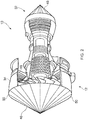
- the first gas shield 46 may have any suitable shape (for example, a conical shape as illustrated in Figs. 1 and 2 ) that defines a perimeter 50 that is arranged to couple to the gas turbine engine 10 around the inlet 16.
- the perimeter 50 of the first gas shield 46 may be coupled to the fan case 34 adjacent to the inlet 16 via a plurality of fasteners (such as clips or pegs).
- the perimeter 50 of the first gas shield 46 may comprise an elastic annulus that provides a radially compressive force to the fan case 34 adjacent to the inlet 16.
- the first gas shield 46 may comprise any suitable impermeable material that prevents the flow of a fluid there through.
- the first gas shield 46 may comprise rubber, polyvinyl chloride (PVC), polyurethane (PU), silicone elastomer, or fluoropolymer.
- the second gas shield 48 is arranged to cover the exhaust nozzle 32 of the gas turbine engine 10.
- the second gas shield 48 may have any suitable shape (for example, a conical shape as illustrated in Figs. 1 and 2 ) that defines a perimeter 52 that is arranged to couple to the gas turbine engine 10 around the exhaust nozzle 32.
- the perimeter 52 of the second gas shield 48 may be coupled to the engine case 36 adjacent to the exhaust nozzle 32 via a plurality of fasteners (such as clips or pegs).
- the perimeter 52 of the second gas shield 48 may comprise an elastic annulus that provides a radially compressive force to the engine case 36 adjacent to the exhaust nozzle 32.
- the second gas shield 48 may comprise any suitable impermeable material that prevents the flow of a fluid there through.
- the second gas shield 48 may comprise rubber, polyvinyl chloride (PVC), polyurethane (PU), silicone elastomer, or fluoropolymer.
- Fig. 3 illustrates a cross sectional view of the gas turbine engine 10 and another gas shield arrangement 121 according to various examples.
- the gas shield arrangement 121 is similar to the gas shield arrangement 12 illustrated in Figs. 1 and 2 , and where the features are similar, the same reference numerals are used.
- the gas shield arrangement 121 differs from the gas shield arrangement 12 in that the gas shield arrangement 121 further comprises a fluid reservoir 54, a pump 56, a first valve 58, a second valve 60, a sensor 62, and a continuum robot 64.
- the fluid reservoir 54 may include one or more containers that comprise one or more fluids respectively for enabling one or more actions to be performed within the first gas flow path 38 and/or the second gas flow path 40 of the gas turbine engine 10.
- the fluid reservoir 54 may comprise one or more inert gases such as argon and/or nitrogen to enable a welding activity to be performed in the first gas flow path 38 and/or the second gas flow path 40.
- the pump 56 may comprise any suitable pump or pumps for pumping fluid from the fluid reservoir 54 to the first valve 58.
- the pump 56 may include one or more centrifugal pumps between the fluid reservoir 54 and the first valve 58 to supply fluid from the fluid reservoir 54 to the first valve 58.
- the pump 56 may include one or more axial flow pumps between the fluid reservoir 54 and the first valve 58 to supply fluid from the fluid reservoir 54 to the first valve 58.
- the first valve 58 is configured to control a flow of fluid through the first gas shield 46.
- the first valve 58 may comprise any suitable structure and may be positioned at any location on the first gas shield 46.
- the first valve 58 is configured to receive fluid from the pump 56 and allow the fluid to flow through the first gas shield 46 and into the first gas flow path 38 and the second gas flow path 40.
- the first valve 58 is also configured to prevent fluid from flowing in the opposite direction (that is, from the first and second gas flow paths 38, 40, through the fan 18, and into the environment around the gas turbine engine 10).
- the second valve 60 is configured to control a flow of fluid through the second gas shield 48.
- the second valve 60 may comprise any suitable structure and may be positioned at any location on the second gas shield 48.
- the second valve 60 is configured to receive fluid from the first gas flow path 38 and allow the fluid to flow through the second gas shield 48. The fluid may then return to the fluid reservoir 54 and/or flow to the sensor 62.
- the second valve 60 is also configured to prevent fluid from flowing in the opposite direction (that is, from the environment outside of the gas turbine engine 10 and into the first gas flow path 38).
- the second valve 60 may be configured to receive fluid from the pump 56 and allow the fluid to flow through the second gas shield 48 to the first gas flow path 38.
- the first valve 58 may be configured to receive fluid from the first gas flow path 38 and allow the fluid to flow through the first gas shield 46 and return to the fluid reservoir 54 and/or flow to the sensor 62.
- the sensor 62 may comprise any suitable sensor or sensors for analysing the fluid exhausted from the second valve 60.
- the sensor 62 may include a chemical sensor that monitors the composition of the gas to check for impurities.
- the sensor 62 may be configured to exhaust the fluid into the environment outside of the gas turbine engine 10, or may be configured to provide the fluid to the fluid reservoir 54, or may be configured to provide the fluid to a further container (not illustrated) for later waste disposal.
- the continuum robot 64 is configured to perform an action within the gas turbine engine 10.
- the continuum robot 64 may be configured to perform a repair activity and/or an inspection activity within the gas turbine engine 10.
- the continuum robot 64 may include a controller 66, a snake arm 68, and a tool 70.
- the controller 66 may comprise any suitable circuitry to control operation of the snake arm 68 and the tool 70.
- the controller 66 may comprise: control circuitry; and/or processor circuitry; and/or at least one application specific integrated circuit (ASIC); and/or at least one field programmable gate array (FPGA); and/or single or multi-processor architectures; and/or sequential/parallel architectures; and/or at least one programmable logic controllers (PLCs); and/or at least one microprocessor; and/or at least one microcontroller; and/or a central processing unit (CPU); and/or a graphics processing unit (GPU).
- the controller 66 may include at least one processor and at least one memory.
- the memory stores a computer program comprising computer readable instructions that, when read by the processor, controls operation of the snake arm 68 and the tool 70.
- the snake arm 68 is configured to be inserted into the gas turbine engine 10 via a borescope port 72 in the engine case 36.
- the snake arm 68 may comprise any suitable structure and may comprise, for example, a plurality of disks connected to one another via a plurality of joints that may be controllably oriented by one or more cables that extend along the length of the snake arm 68 and are connected to one or more servomotors respectively.
- the tool 70 is mounted on the snake arm 68 and is also configured to be inserted into the gas turbine engine 10 via the borescope port 72 in the engine case 36.
- the tool 70 may comprise any device that enables the continuum robot 64 to perform an action (such as a repair activity or an inspection activity) in the gas turbine engine 10.
- the tool 70 may comprise welding apparatus for repairing the gas turbine engine 10.
- the tool 70 may comprise an electron beam emitter for performing electron tomography.
- a plurality of continuum robots 64 may be inserted into the gas turbine engine 10 via a plurality of borescope ports 72 while fluid is pumped through the first gas flow path 38. Furthermore, one or more continuum robots 64 may be inserted into the bypass duct 42 while fluid is pumped through the second gas flow path 40.
- Fig. 4 illustrates a cross sectional view of the gas turbine engine 10 and a further gas shield arrangement 122 according to various examples.
- the gas shield arrangement 122 is similar to the gas shield arrangement 121 illustrated in Fig. 3 and where the features are similar, the same reference numerals are used.
- the gas shield arrangement 122 differs from the gas shield arrangement 121 in that the gas shield arrangement 122 further comprises a third gas shield 74 that is arranged to cover the outlet 44 of the bypass duct 42.
- the third gas shield 74 has an annulus shape and defines an inner edge 76 and an outer edge 78.
- the third gas shield 74 may comprise any suitable impermeable material that prevents the flow of a fluid there through.
- the third gas shield 74 may comprise rubber, polyvinyl chloride (PVC), polyurethane (PU), silicone elastomer, or fluoropolymer.
- the inner edge 76 has a diameter that is greater than the maximum diameter of the engine case 36 aft of the fan case 34 to enable the third gas shield 74 to move over the rear of the gas turbine engine 10 and into the position illustrated in Fig. 4 .
- the inner edge 76 is arranged to couple to the engine case 36.
- the inner edge 76 of the third gas shield 74 may be coupled to the engine case 36 via a plurality of fasteners (such as clips or pegs).
- the inner edge 76 of the third gas shield 74 may comprise an elastic annulus that provides a radially compressive force to the engine case 36.
- the outer edge 78 has a diameter that is equal to or greater than the diameter of the fan case 34.
- the outer edge 78 is arranged to couple to the fan case 34.
- the outer edge 78 of the third gas shield 74 may be coupled to the fan case 34 via a plurality of fasteners (such as clips or pegs).
- the outer edge 78 of the third gas shield 74 may comprise an elastic annulus that provides a radially compressive force to the fan case 34 adjacent to the outlet 44.
- the third gas shield 74 may comprise a third valve 80 to control a flow of fluid through the third gas shield 74.
- the third valve 80 may have any suitable structure and may be located at any position in the third gas shield 74.
- the third valve 80 may be connected to the pump 56 and may function as an inlet for fluid into the bypass duct 42.
- the third valve 80 may function as an exhaust for fluid within the gas turbine engine 10 and may be connected to the fluid reservoir 54 to enable fluid to be recycled.
- the third valve 80 may be connected to the sensor 62 to enable the fluid to be analysed.
- the gas shield arrangement 122 also differs from the gas shield arrangement 121 in that the gas shield arrangement 122 may further comprise a fourth valve 82 to control a flow of fluid through a borescope port of the gas turbine engine 10 (such as the borescope port 72).
- the fourth valve 82 may be connected to the pump 56 and may function as an inlet for fluid into the first gas flow path 38.
- the fourth valve 82 may function as an exhaust for fluid within the gas turbine engine 10 and may be connected to the fluid reservoir 54 to enable fluid to be recycled.
- the fourth valve 82 may be connected to the sensor 62 to enable the fluid to be analysed.
- the continuum robot 64 may enter the first gas flow path 38 via the fourth valve 82 and the borescope port 72.
- any one or more of the first valve 58, the second valve 60, the third valve 80 and the fourth valve 82 may be connected to the pump 56 to receive fluid from the fluid reservoir 54 and that any of the other valves may be used as an exhaust.
- the remaining valves may be used by the continuum robot 64 to enter the gas turbine engine 10.
- the third valve 80 may be connected to the pump 56 to receive fluid from the fluid reservoir 54
- the fourth valve 82 or the second valve 60 may be used to exhaust fluid from the gas turbine engine 10
- the first valve 58 may be used by the continuum robot 64 to enter the gas turbine engine 10 from the front to perform an action.
- Fig. 5 illustrates a flow diagram of a method of gas shielding an interior of a gas turbine engine 10 according to various examples.
- the method includes covering the inlet 16 of the gas flow path 38, 40 of the gas turbine engine 10 using the first gas shield 46.
- the first gas shield 46 may be coupled to the fan case 34 around the inlet 16 to prevent the flow of fluid between the interior of the gas turbine engine 10 and the environment via the inlet 16.
- the method may include covering the outlet 32 of the gas flow path 38 of the gas turbine engine 10 using the second gas shield 48.
- the second gas shield 48 may be coupled to the engine case 36 around the exhaust nozzle 32 to prevent the flow of fluid between the interior of the gas turbine engine 10 and the environment via the exhaust nozzle 32.
- the method may include covering the outlet 44 of the gas flow path 40 of the gas turbine engine 10 using the third gas shield 74.
- the third gas shield 74 may be coupled to the engine case 36 and to the fan case 34 to prevent the flow of fluid between the bypass duct 42 and the environment via the outlet 44.
- the method may include providing one or more fourth valves 82 to control a flow of fluid through one or more borescope ports 72 respectively.
- the method may include providing a continuum robot 64.
- the continuum robot 64 may be inserted into the gas turbine engine 10 via the first valve 58, the second valve 60, the third valve 80 or the fourth valve 82.
- the method may include pumping a fluid to one or more of the first valve 58, the second valve 60, the third valve 80, and the fourth valve 82.
- the pump 56 may pump an inert gas such as argon or nitrogen to the first valve 58 so that the inert gas flows through the first gas flow path 38 and the second gas flow path 40.
- the method may include performing an action within the first gas flow path 38 or the second gas flow path 40 of the gas turbine engine 10 using the continuum robot 64.
- the continuum robot 64 may perform a repair activity (such as welding) or an inspect activity on the intermediate pressure turbine 28 or the low pressure turbine 30.
- the apparatus 12, 121, 122 may provide several advantages.
- the apparatus 12, 121, 122 may enable an inspection activity or a repair activity (that benefits from, or requires, a controlled atmosphere) to be performed within the gas turbine engine 10 without the gas turbine engine 10 being disassembled.
- the first, second and third gas shields 46, 48 and 74 may be used to cover the openings of the gas turbine engine 10 while the gas turbine engine 10 is mounted to an aircraft (for example, a wing of an aircraft) and the continuum robot 64 may then be inserted through the borescope port 72 to perform an inspection activity or a repair activity. This may significantly reduce the time and cost for performing such an activity within the gas turbine engine 10.
- the apparatus 12, 121, 122 may be used to assist with the cooling of one or more components of the gas turbine engine 10 subsequent to a repair activity having been performed.
- one or more of the first valve 58, the second valve 60, the third valve 80 and the fourth valve 82 may be coupled to a reservoir of cooling fluid and the cooling fluid may then be pumped through the first gas flow path 38 and/or the second gas flow path 40 to cool a component that has recently been welded.
- the apparatus 12, 121, 122 may be used to assist with the removal of contamination within the gas turbine engine 10 subsequent to a repair activity having been performed.
- one or more of the first valve 58, the second valve 60, the third valve 80 and the fourth valve 82 may be coupled to a reservoir of cleaning fluid and the cleaning fluid may then be pumped through the first gas flow path 38 and/or the second gas flow path 40 to remove contamination from the repair area.
- the apparatus 10, 121, 122 may be used to remove fluid from the gas turbine engine 10.
- the first valve 58, the second valve 60, the third valve 80 and the fourth valve 82 may be configured to allow the egress of fluid from the gas turbine engine 10 to the environment (and prevent the ingress of fluid into the gas turbine engine 10).
- One or more of the first valve 58, the second valve 60, the third valve 80 and the fourth valve 82 may be connected to a vacuum pump to remove fluid from (and thereby evacuate) the interior of the gas turbine engine 10. This may be advantageous where a repair activity or an inspection activity benefits from (or requires) a vacuum.
Landscapes
- Engineering & Computer Science (AREA)
- Chemical & Material Sciences (AREA)
- Combustion & Propulsion (AREA)
- Mechanical Engineering (AREA)
- General Engineering & Computer Science (AREA)
- Structures Of Non-Positive Displacement Pumps (AREA)
- Laser Beam Processing (AREA)
Abstract
Description
- The present disclosure concerns gas shielding arrangements for gas turbine engines.
- Gas turbine engines may sustain wear and/or damage during operation that may reduce the efficiency of the gas turbine engine. Repair of the gas turbine engine may be a relatively time consuming task and may require disassembly of the gas turbine engine. For example, gas turbine engines used in aviation are usually mounted on a wing of an aircraft and a repair process may require the gas turbine engine to be removed from the wing of the aircraft and then disassembled to allow access to the worn and/or damaged component. This repair process may be relatively expensive in terms of cost, working hours and time out of operation for the engine.
- According to various examples there is provided a gas shield arrangement for a gas turbine engine, the gas shield arrangement comprising: a first gas shield arranged to cover an inlet of a gas flow path of the gas turbine engine; and a second gas shield arranged to cover a first outlet of the gas flow path of the gas turbine engine.
- The first gas shield may have a perimeter that is arranged to couple to the gas turbine engine around the inlet.
- The second gas shield may have a perimeter that is arranged to couple to the gas turbine engine around the first outlet.
- The first gas shield may comprise a first valve to control a flow of fluid through the first gas shield.
- The second gas shield may comprise a second valve to control a flow of fluid through the second gas shield.
- The gas shield arrangement may further comprise a third gas shield arranged to cover a second outlet of the gas flow path of the gas turbine engine.
- The third gas shield may comprise a third valve to control a flow of fluid through the third gas shield.
- The gas shield arrangement may further comprise a fourth valve to control a flow of fluid through a borescope port of the gas turbine engine.
- According to various examples there is provided apparatus comprising: a gas shield arrangement as described in any of the preceding paragraphs; and a continuum robot for performing an action within the gas turbine engine.
- The action may be welding a component of the gas turbine engine.
- According to various examples there is provided a method of gas shielding a gas turbine engine, the method comprising: covering an inlet of a gas flow path of the gas turbine engine using a first gas shield; and covering a first outlet of the gas flow path of the gas turbine engine using a second gas shield.
- The first gas shield may have a perimeter that is arranged to couple to the gas turbine engine around the inlet.
- The second gas shield may have a perimeter that is arranged to couple to the gas turbine engine around the first outlet.
- The first gas shield may comprise a first valve to control a flow of fluid through the first gas shield.
- The second gas shield may comprise a second valve to control a flow of fluid through the second gas shield.
- The method may further comprise covering a second outlet of the gas flow path of the gas turbine engine using a third gas shield.
- The third gas shield may comprise a third valve to control a flow of fluid through the third gas shield.
- The method may further comprise providing a fourth valve to control a flow of fluid through a borescope port of the gas turbine engine.
- The method may further comprise providing a continuum robot; and performing an action within the gas turbine engine using the continuum robot.
- The action may be welding a component of the gas turbine engine.
- The skilled person will appreciate that except where mutually exclusive, a feature described in relation to any one of the above aspects may be applied mutatis mutandis to any other aspect. Furthermore except where mutually exclusive any feature described herein may be applied to any aspect and/or combined with any other feature described herein.
- Embodiments will now be described by way of example only, with reference to the Figures, in which:
-
Fig. 1 illustrates a cross sectional side view of a gas turbine engine and a gas shield arrangement according to various examples; -
Fig. 2 illustrates a perspective view of the gas turbine engine and the gas shield arrangement illustrated inFig. 1 ; -
Fig. 3 illustrates a cross sectional side view of the gas turbine engine and another gas shield arrangement according to various examples; -
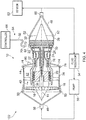
Fig. 4 illustrates a cross sectional side view of the gas turbine engine and a further gas shield arrangement according to various examples; and -
Fig. 5 illustrates a flow diagram of a method of gas shielding a gas turbine engine according to various examples. - In the following description, the terms 'connected' and 'coupled' mean operationally connected and coupled. It should be appreciated that there may be any number of intervening components between the mentioned features, including no intervening components.
-
Fig. 1 illustrates agas turbine engine 10 and agas shield arrangement 12 according to various examples. Thegas turbine engine 10 may be used in any industry and may be, for example, an aerospace gas turbine engine mounted on an aeroplane, a marine gas turbine engine mounted within a vessel, or an industrial gas turbine engine for generating electricity. - The
gas turbine engine 10 has arotational axis 14 and comprises, in axial flow series, anair intake 16, afan 18, anintermediate pressure compressor 20, a high-pressure compressor 22,combustion equipment 24, a high-pressure turbine 26, anintermediate pressure turbine 28, a low-pressure turbine 30 and an exhaust nozzle 32 (which may be referred to as an outlet). Afan case 34 defines an annulus that houses thefan 18, and anengine case 36 defines an annulus that houses theintermediate pressure compressor 20, thehigh pressure compressor 22, thecombustion equipment 24, thehigh pressure turbine 26, theintermediate pressure turbine 28, thelow pressure turbine 30 and defines theexhaust nozzle 32. - Where the
gas turbine engine 10 is an aerospace gas turbine engine, a nacelle (not illustrated in the figures to maintain clarity) generally surrounds the gas turbine engine and is coupled to thefan case 34. The nacelle may include one or more doors for providing access to thefan case 34 and theengine case 36 when thegas turbine engine 10 is mounted on an aircraft. - The
gas turbine engine 10 operates so that air entering theintake 16 is accelerated by thefan 18 to produce two gas flow paths: a firstgas flow path 38 into theintermediate pressure compressor 20 and a secondgas flow path 40 which passes through abypass duct 42 to provide propulsive thrust. The second gas flow is exhausted from thebypass duct 42 via anoutlet 44. - The
intermediate pressure compressor 20 compresses the air flow directed into it before delivering that air to thehigh pressure compressor 22 where further compression takes place. The compressed air exhausted from the high-pressure compressor 22 is directed into thecombustion equipment 24 where it is mixed with fuel and the mixture combusted. The resultant hot combustion products then expand through, and thereby drive the high, intermediate and low-pressure turbines nozzle 32 to provide additional propulsive thrust. Thehigh pressure turbine 26, theintermediate pressure turbine 28 and thelow pressure turbine 30 drive thehigh pressure compressor 22, theintermediate pressure compressor 20 and thefan 18 respectively, each by an interconnecting shaft. - Other gas turbine engines to which the present disclosure may be applied may have alternative configurations. By way of example, such engines may have an alternative number of interconnecting shafts (e.g. two) and/or an alternative number of compressors and/or turbines. Furthermore, the gas turbine engine may comprise a gearbox provided in the drive train from a turbine to a compressor and/or fan.
- In summary, the
gas shield arrangement 12 is configured to cover at least some of the openings to the firstgas flow path 38 and/or the secondgas flow path 40 to prevent the egress of a fluid (such as an inert gas) from the firstgas flow path 38 and/or the secondgas flow path 40. This may enable an action that benefits from (or requires) a controlled atmosphere (such as a repair activity and/or an inspection activity) to be performed within the firstgas flow path 38 and/or the secondgas flow path 40. - In more detail, the
gas shield arrangement 12 includes afirst gas shield 46 and asecond gas shield 48. - The
first gas shield 46 is arranged to cover theinlet 16 of thegas turbine engine 10. Thefirst gas shield 46 may have any suitable shape (for example, a conical shape as illustrated inFigs. 1 and2 ) that defines aperimeter 50 that is arranged to couple to thegas turbine engine 10 around theinlet 16. For example, theperimeter 50 of thefirst gas shield 46 may be coupled to thefan case 34 adjacent to theinlet 16 via a plurality of fasteners (such as clips or pegs). By way of another example, theperimeter 50 of thefirst gas shield 46 may comprise an elastic annulus that provides a radially compressive force to thefan case 34 adjacent to theinlet 16. Thefirst gas shield 46 may comprise any suitable impermeable material that prevents the flow of a fluid there through. For example, thefirst gas shield 46 may comprise rubber, polyvinyl chloride (PVC), polyurethane (PU), silicone elastomer, or fluoropolymer. - The
second gas shield 48 is arranged to cover theexhaust nozzle 32 of thegas turbine engine 10. Thesecond gas shield 48 may have any suitable shape (for example, a conical shape as illustrated inFigs. 1 and2 ) that defines aperimeter 52 that is arranged to couple to thegas turbine engine 10 around theexhaust nozzle 32. In some examples, theperimeter 52 of thesecond gas shield 48 may be coupled to theengine case 36 adjacent to theexhaust nozzle 32 via a plurality of fasteners (such as clips or pegs). By way of another example, theperimeter 52 of thesecond gas shield 48 may comprise an elastic annulus that provides a radially compressive force to theengine case 36 adjacent to theexhaust nozzle 32. Thesecond gas shield 48 may comprise any suitable impermeable material that prevents the flow of a fluid there through. For example, thesecond gas shield 48 may comprise rubber, polyvinyl chloride (PVC), polyurethane (PU), silicone elastomer, or fluoropolymer. -
Fig. 3 illustrates a cross sectional view of thegas turbine engine 10 and anothergas shield arrangement 121 according to various examples. Thegas shield arrangement 121 is similar to thegas shield arrangement 12 illustrated inFigs. 1 and2 , and where the features are similar, the same reference numerals are used. - The
gas shield arrangement 121 differs from thegas shield arrangement 12 in that thegas shield arrangement 121 further comprises afluid reservoir 54, apump 56, afirst valve 58, asecond valve 60, asensor 62, and acontinuum robot 64. - The
fluid reservoir 54 may include one or more containers that comprise one or more fluids respectively for enabling one or more actions to be performed within the firstgas flow path 38 and/or the secondgas flow path 40 of thegas turbine engine 10. For example, thefluid reservoir 54 may comprise one or more inert gases such as argon and/or nitrogen to enable a welding activity to be performed in the firstgas flow path 38 and/or the secondgas flow path 40. - The
pump 56 may comprise any suitable pump or pumps for pumping fluid from thefluid reservoir 54 to thefirst valve 58. For example, thepump 56 may include one or more centrifugal pumps between thefluid reservoir 54 and thefirst valve 58 to supply fluid from thefluid reservoir 54 to thefirst valve 58. In another example, thepump 56 may include one or more axial flow pumps between thefluid reservoir 54 and thefirst valve 58 to supply fluid from thefluid reservoir 54 to thefirst valve 58. - The
first valve 58 is configured to control a flow of fluid through thefirst gas shield 46. Thefirst valve 58 may comprise any suitable structure and may be positioned at any location on thefirst gas shield 46. Thefirst valve 58 is configured to receive fluid from thepump 56 and allow the fluid to flow through thefirst gas shield 46 and into the firstgas flow path 38 and the secondgas flow path 40. Thefirst valve 58 is also configured to prevent fluid from flowing in the opposite direction (that is, from the first and secondgas flow paths fan 18, and into the environment around the gas turbine engine 10). - The
second valve 60 is configured to control a flow of fluid through thesecond gas shield 48. Thesecond valve 60 may comprise any suitable structure and may be positioned at any location on thesecond gas shield 48. Thesecond valve 60 is configured to receive fluid from the firstgas flow path 38 and allow the fluid to flow through thesecond gas shield 48. The fluid may then return to thefluid reservoir 54 and/or flow to thesensor 62. Thesecond valve 60 is also configured to prevent fluid from flowing in the opposite direction (that is, from the environment outside of thegas turbine engine 10 and into the first gas flow path 38). - It should be appreciated that in other examples, the
second valve 60 may be configured to receive fluid from thepump 56 and allow the fluid to flow through thesecond gas shield 48 to the firstgas flow path 38. Similarly, thefirst valve 58 may be configured to receive fluid from the firstgas flow path 38 and allow the fluid to flow through thefirst gas shield 46 and return to thefluid reservoir 54 and/or flow to thesensor 62. - The
sensor 62 may comprise any suitable sensor or sensors for analysing the fluid exhausted from thesecond valve 60. For example, thesensor 62 may include a chemical sensor that monitors the composition of the gas to check for impurities. Thesensor 62 may be configured to exhaust the fluid into the environment outside of thegas turbine engine 10, or may be configured to provide the fluid to thefluid reservoir 54, or may be configured to provide the fluid to a further container (not illustrated) for later waste disposal. - The
continuum robot 64 is configured to perform an action within thegas turbine engine 10. For example, thecontinuum robot 64 may be configured to perform a repair activity and/or an inspection activity within thegas turbine engine 10. Thecontinuum robot 64 may include acontroller 66, asnake arm 68, and atool 70. - The
controller 66 may comprise any suitable circuitry to control operation of thesnake arm 68 and thetool 70. Thecontroller 66 may comprise: control circuitry; and/or processor circuitry; and/or at least one application specific integrated circuit (ASIC); and/or at least one field programmable gate array (FPGA); and/or single or multi-processor architectures; and/or sequential/parallel architectures; and/or at least one programmable logic controllers (PLCs); and/or at least one microprocessor; and/or at least one microcontroller; and/or a central processing unit (CPU); and/or a graphics processing unit (GPU). In some examples, thecontroller 66 may include at least one processor and at least one memory. The memory stores a computer program comprising computer readable instructions that, when read by the processor, controls operation of thesnake arm 68 and thetool 70. - The
snake arm 68 is configured to be inserted into thegas turbine engine 10 via aborescope port 72 in theengine case 36. Thesnake arm 68 may comprise any suitable structure and may comprise, for example, a plurality of disks connected to one another via a plurality of joints that may be controllably oriented by one or more cables that extend along the length of thesnake arm 68 and are connected to one or more servomotors respectively. - The
tool 70 is mounted on thesnake arm 68 and is also configured to be inserted into thegas turbine engine 10 via theborescope port 72 in theengine case 36. Thetool 70 may comprise any device that enables thecontinuum robot 64 to perform an action (such as a repair activity or an inspection activity) in thegas turbine engine 10. For example, thetool 70 may comprise welding apparatus for repairing thegas turbine engine 10. By way of another example, thetool 70 may comprise an electron beam emitter for performing electron tomography. - It should be appreciated that a plurality of
continuum robots 64 may be inserted into thegas turbine engine 10 via a plurality ofborescope ports 72 while fluid is pumped through the firstgas flow path 38. Furthermore, one ormore continuum robots 64 may be inserted into thebypass duct 42 while fluid is pumped through the secondgas flow path 40. -
Fig. 4 illustrates a cross sectional view of thegas turbine engine 10 and a furthergas shield arrangement 122 according to various examples. Thegas shield arrangement 122 is similar to thegas shield arrangement 121 illustrated inFig. 3 and where the features are similar, the same reference numerals are used. - The
gas shield arrangement 122 differs from thegas shield arrangement 121 in that thegas shield arrangement 122 further comprises athird gas shield 74 that is arranged to cover theoutlet 44 of thebypass duct 42. Thethird gas shield 74 has an annulus shape and defines aninner edge 76 and anouter edge 78. Thethird gas shield 74 may comprise any suitable impermeable material that prevents the flow of a fluid there through. For example, thethird gas shield 74 may comprise rubber, polyvinyl chloride (PVC), polyurethane (PU), silicone elastomer, or fluoropolymer. - The
inner edge 76 has a diameter that is greater than the maximum diameter of theengine case 36 aft of thefan case 34 to enable thethird gas shield 74 to move over the rear of thegas turbine engine 10 and into the position illustrated inFig. 4 . Theinner edge 76 is arranged to couple to theengine case 36. For example, theinner edge 76 of thethird gas shield 74 may be coupled to theengine case 36 via a plurality of fasteners (such as clips or pegs). By way of another example, theinner edge 76 of thethird gas shield 74 may comprise an elastic annulus that provides a radially compressive force to theengine case 36. - The
outer edge 78 has a diameter that is equal to or greater than the diameter of thefan case 34. Theouter edge 78 is arranged to couple to thefan case 34. For example, theouter edge 78 of thethird gas shield 74 may be coupled to thefan case 34 via a plurality of fasteners (such as clips or pegs). By way of another example, theouter edge 78 of thethird gas shield 74 may comprise an elastic annulus that provides a radially compressive force to thefan case 34 adjacent to theoutlet 44. - The
third gas shield 74 may comprise athird valve 80 to control a flow of fluid through thethird gas shield 74. Thethird valve 80 may have any suitable structure and may be located at any position in thethird gas shield 74. Thethird valve 80 may be connected to thepump 56 and may function as an inlet for fluid into thebypass duct 42. Alternatively, thethird valve 80 may function as an exhaust for fluid within thegas turbine engine 10 and may be connected to thefluid reservoir 54 to enable fluid to be recycled. Additionally or alternatively, thethird valve 80 may be connected to thesensor 62 to enable the fluid to be analysed. - The
gas shield arrangement 122 also differs from thegas shield arrangement 121 in that thegas shield arrangement 122 may further comprise afourth valve 82 to control a flow of fluid through a borescope port of the gas turbine engine 10 (such as the borescope port 72). Thefourth valve 82 may be connected to thepump 56 and may function as an inlet for fluid into the firstgas flow path 38. Alternatively, thefourth valve 82 may function as an exhaust for fluid within thegas turbine engine 10 and may be connected to thefluid reservoir 54 to enable fluid to be recycled. Additionally, or alternatively, thefourth valve 82 may be connected to thesensor 62 to enable the fluid to be analysed. Thecontinuum robot 64 may enter the firstgas flow path 38 via thefourth valve 82 and theborescope port 72. - It should be appreciated that any one or more of the
first valve 58, thesecond valve 60, thethird valve 80 and thefourth valve 82 may be connected to thepump 56 to receive fluid from thefluid reservoir 54 and that any of the other valves may be used as an exhaust. The remaining valves may be used by thecontinuum robot 64 to enter thegas turbine engine 10. For example, thethird valve 80 may be connected to thepump 56 to receive fluid from thefluid reservoir 54, thefourth valve 82 or thesecond valve 60 may be used to exhaust fluid from thegas turbine engine 10, and thefirst valve 58 may be used by thecontinuum robot 64 to enter thegas turbine engine 10 from the front to perform an action. -
Fig. 5 illustrates a flow diagram of a method of gas shielding an interior of agas turbine engine 10 according to various examples. - At
block 84, the method includes covering theinlet 16 of thegas flow path gas turbine engine 10 using thefirst gas shield 46. Thefirst gas shield 46 may be coupled to thefan case 34 around theinlet 16 to prevent the flow of fluid between the interior of thegas turbine engine 10 and the environment via theinlet 16. - At
block 86, the method may include covering theoutlet 32 of thegas flow path 38 of thegas turbine engine 10 using thesecond gas shield 48. Thesecond gas shield 48 may be coupled to theengine case 36 around theexhaust nozzle 32 to prevent the flow of fluid between the interior of thegas turbine engine 10 and the environment via theexhaust nozzle 32. - At
block 88, the method may include covering theoutlet 44 of thegas flow path 40 of thegas turbine engine 10 using thethird gas shield 74. Thethird gas shield 74 may be coupled to theengine case 36 and to thefan case 34 to prevent the flow of fluid between thebypass duct 42 and the environment via theoutlet 44. - At
block 90, the method may include providing one or morefourth valves 82 to control a flow of fluid through one ormore borescope ports 72 respectively. - At
block 92, the method may include providing acontinuum robot 64. For example, thecontinuum robot 64 may be inserted into thegas turbine engine 10 via thefirst valve 58, thesecond valve 60, thethird valve 80 or thefourth valve 82. - At
block 94, the method may include pumping a fluid to one or more of thefirst valve 58, thesecond valve 60, thethird valve 80, and thefourth valve 82. For example, thepump 56 may pump an inert gas such as argon or nitrogen to thefirst valve 58 so that the inert gas flows through the firstgas flow path 38 and the secondgas flow path 40. - At
block 96, the method may include performing an action within the firstgas flow path 38 or the secondgas flow path 40 of thegas turbine engine 10 using thecontinuum robot 64. For example, where thecontinuum robot 64 is inserted through theborescope port 72 illustrated inFigs. 3 and4 , thecontinuum robot 64 may perform a repair activity (such as welding) or an inspect activity on theintermediate pressure turbine 28 or thelow pressure turbine 30. - The
apparatus apparatus gas turbine engine 10 without thegas turbine engine 10 being disassembled. For example, the first, second and third gas shields 46, 48 and 74 may be used to cover the openings of thegas turbine engine 10 while thegas turbine engine 10 is mounted to an aircraft (for example, a wing of an aircraft) and thecontinuum robot 64 may then be inserted through theborescope port 72 to perform an inspection activity or a repair activity. This may significantly reduce the time and cost for performing such an activity within thegas turbine engine 10. - Second, the
apparatus gas turbine engine 10 subsequent to a repair activity having been performed. For example, one or more of thefirst valve 58, thesecond valve 60, thethird valve 80 and thefourth valve 82 may be coupled to a reservoir of cooling fluid and the cooling fluid may then be pumped through the firstgas flow path 38 and/or the secondgas flow path 40 to cool a component that has recently been welded. - Third, the
apparatus gas turbine engine 10 subsequent to a repair activity having been performed. For example, one or more of thefirst valve 58, thesecond valve 60, thethird valve 80 and thefourth valve 82 may be coupled to a reservoir of cleaning fluid and the cleaning fluid may then be pumped through the firstgas flow path 38 and/or the secondgas flow path 40 to remove contamination from the repair area. - It will be understood that the invention is not limited to the embodiments above-described and various modifications and improvements can be made without departing from the concepts described herein. For example, the
apparatus gas turbine engine 10. For example, thefirst valve 58, thesecond valve 60, thethird valve 80 and thefourth valve 82 may be configured to allow the egress of fluid from thegas turbine engine 10 to the environment (and prevent the ingress of fluid into the gas turbine engine 10). One or more of thefirst valve 58, thesecond valve 60, thethird valve 80 and thefourth valve 82 may be connected to a vacuum pump to remove fluid from (and thereby evacuate) the interior of thegas turbine engine 10. This may be advantageous where a repair activity or an inspection activity benefits from (or requires) a vacuum. - Except where mutually exclusive, any of the features may be employed separately or in combination with any other features and the disclosure extends to and includes all combinations and sub-combinations of one or more features described herein.
Claims (15)
- A gas shield arrangement for a gas turbine engine, the gas shield arrangement comprising:a first gas shield arranged to cover an inlet of a gas flow path of the gas turbine engine; anda second gas shield arranged to cover a first outlet of the gas flow path of the gas turbine engine.
- A gas shield arrangement as claimed in claim 1, wherein the first gas shield has a perimeter that is arranged to couple to the gas turbine engine around the inlet.
- A gas shield arrangement as claimed in claim 1 or 2, wherein the second gas shield has a perimeter that is arranged to couple to the gas turbine engine around the first outlet.
- A gas shield arrangement as claimed in any of the preceding claims, wherein the first gas shield comprises a first valve to control a flow of fluid through the first gas shield.
- A gas shield arrangement as claimed in any of the preceding claims, wherein the second gas shield comprises a second valve to control a flow of fluid through the second gas shield.
- A gas shield arrangement as claimed in any of the preceding claims, further comprising a third gas shield arranged to cover a second outlet of the gas flow path of the gas turbine engine.
- A gas shield arrangement as claimed in claim 6, wherein the third gas shield comprises a third valve to control a flow of fluid through the third gas shield.
- A gas shield arrangement as claimed in any of the preceding claims, further comprising a fourth valve to control a flow of fluid through a borescope port of the gas turbine engine.
- Apparatus comprising: a gas shield arrangement as claimed in any of the preceding claims; and a continuum robot for performing an action within the gas turbine engine.
- Apparatus as claimed in claim 9, wherein the action is welding a component of the gas turbine engine.
- A method of gas shielding a gas turbine engine, the method comprising:covering an inlet of a gas flow path of the gas turbine engine using a first gas shield; andcovering a first outlet of the gas flow path of the gas turbine engine using a second gas shield.
- A method as claimed in claims 11, wherein the first gas shield comprises a first valve to control a flow of fluid through the first gas shield and the second gas shield comprises a second valve to control a flow of fluid through the second gas shield.
- A method as claimed in claim 11 or 12, further comprising: covering a second outlet of the gas flow path of the gas turbine engine using a third gas shield, the third gas shield comprises a third valve to control a flow of fluid through the third gas shield; and providing a fourth valve to control a flow of fluid through a borescope port of the gas turbine engine.
- A method as claimed in any of claims 11 to 13, further comprising providing a continuum robot; and performing an action within the gas turbine engine using the continuum robot.
- A method as claimed in claim 14, wherein the action is welding a component of the gas turbine engine.
Applications Claiming Priority (1)
| Application Number | Priority Date | Filing Date | Title |
|---|---|---|---|
| GBGB1615149.0A GB201615149D0 (en) | 2016-09-07 | 2016-09-07 | Gas shielding arrangements for gas turbine engines |
Publications (2)
| Publication Number | Publication Date |
|---|---|
| EP3293352A1 true EP3293352A1 (en) | 2018-03-14 |
| EP3293352B1 EP3293352B1 (en) | 2019-01-02 |
Family
ID=57140060
Family Applications (1)
| Application Number | Title | Priority Date | Filing Date |
|---|---|---|---|
| EP17185239.5A Active EP3293352B1 (en) | 2016-09-07 | 2017-08-08 | Gas shielding arrangements for gas turbine engines |
Country Status (3)
| Country | Link |
|---|---|
| US (1) | US10683775B2 (en) |
| EP (1) | EP3293352B1 (en) |
| GB (1) | GB201615149D0 (en) |
Families Citing this family (1)
| Publication number | Priority date | Publication date | Assignee | Title |
|---|---|---|---|---|
| US11084169B2 (en) * | 2018-05-23 | 2021-08-10 | General Electric Company | System and method for controlling a robotic arm |
Citations (3)
| Publication number | Priority date | Publication date | Assignee | Title |
|---|---|---|---|---|
| JPS55112825A (en) * | 1979-02-23 | 1980-09-01 | Yokohama Rubber Co Ltd:The | Airtight closure for aircraft engine |
| US20060062911A1 (en) * | 2004-09-22 | 2006-03-23 | Medford Glenn M | Process for corrosion protection of turbine internal components |
| EP2522816A2 (en) * | 2011-05-09 | 2012-11-14 | Rolls-Royce plc | A method of supporting a tool in an assembled apparatus |
Family Cites Families (14)
| Publication number | Priority date | Publication date | Assignee | Title |
|---|---|---|---|---|
| US6010746A (en) | 1998-02-03 | 2000-01-04 | United Technologies Corporation | In-situ repair method for a turbomachinery component |
| US6049979A (en) * | 1998-10-20 | 2000-04-18 | General Electric Co. | Methods for shielding a welding gas turbine repair of a damaged turbine rotor wheel dovetail |
| US20030127493A1 (en) | 2002-01-07 | 2003-07-10 | David Ciriza | Purge gas welding ring |
| US7137544B2 (en) * | 2002-12-13 | 2006-11-21 | General Electric Company | Apparatus and method for performing welding at elevated temperature |
| US6841195B2 (en) | 2002-12-18 | 2005-01-11 | General Electric Company | Process for corrosion protection of turbine internal components |
| GB0705696D0 (en) * | 2007-03-24 | 2007-05-02 | Rolls Royce Plc | A method of repairing a damaged abradable coating |
| US20090026173A1 (en) * | 2007-07-26 | 2009-01-29 | General Electric Company | Method and apparatus for welding an article |
| GB0723244D0 (en) * | 2007-11-28 | 2008-01-09 | Rolls Royce Plc | Shaped metal deposition apparatus |
| GB0723327D0 (en) * | 2007-11-29 | 2008-01-09 | Rolls Royce Plc | A shield |
| GB2477322B (en) * | 2010-02-01 | 2015-10-21 | Gas Recovery & Recycle Ltd | Inert gas recovery system |
| US8721772B2 (en) * | 2012-04-05 | 2014-05-13 | Babcock & Wilcox Mpower, Inc. | Systems and methods for performing industrial processes that generate pyrophoric particles |
| US9341300B2 (en) | 2012-04-27 | 2016-05-17 | Michael Hacikyan | Inflatable purge dam apparatus |
| JP6125394B2 (en) | 2013-09-30 | 2017-05-10 | 三菱日立パワーシステムズ株式会社 | Rust prevention unit and sealing device for gas turbine |
| US10443385B2 (en) * | 2016-02-03 | 2019-10-15 | General Electric Company | In situ gas turbine prevention of crack growth progression via laser welding |
-
2016
- 2016-09-07 GB GBGB1615149.0A patent/GB201615149D0/en not_active Ceased
-
2017
- 2017-08-08 US US15/671,813 patent/US10683775B2/en active Active
- 2017-08-08 EP EP17185239.5A patent/EP3293352B1/en active Active
Patent Citations (3)
| Publication number | Priority date | Publication date | Assignee | Title |
|---|---|---|---|---|
| JPS55112825A (en) * | 1979-02-23 | 1980-09-01 | Yokohama Rubber Co Ltd:The | Airtight closure for aircraft engine |
| US20060062911A1 (en) * | 2004-09-22 | 2006-03-23 | Medford Glenn M | Process for corrosion protection of turbine internal components |
| EP2522816A2 (en) * | 2011-05-09 | 2012-11-14 | Rolls-Royce plc | A method of supporting a tool in an assembled apparatus |
Also Published As
| Publication number | Publication date |
|---|---|
| EP3293352B1 (en) | 2019-01-02 |
| GB201615149D0 (en) | 2016-10-19 |
| US10683775B2 (en) | 2020-06-16 |
| US20180066544A1 (en) | 2018-03-08 |
Similar Documents
| Publication | Publication Date | Title |
|---|---|---|
| GB2553144B (en) | Apparatus for insertion into a cavity of an object | |
| US11519293B2 (en) | Cleaning system and a method of cleaning | |
| US9382844B2 (en) | Mid-turbine frame buffer system | |
| CN104981591B (en) | Pressurized Feed Oil Drain for Gas Turbine Engine Tanks | |
| US10227875B2 (en) | Gas turbine engine component with combined mate face and platform cooling | |
| US10107157B2 (en) | Gas turbine engine lubrication system | |
| US10940938B2 (en) | Pitch-changing system equipped with means for lubricating a load-transfer bearing | |
| US12345167B2 (en) | System and method of using a tool assembly | |
| EP4276295A3 (en) | Geared turbofan with overspeed protection | |
| CA2951800C (en) | Method and system for in-line distributed propulsion | |
| US10132246B2 (en) | Bleed valve assembly | |
| US10683775B2 (en) | Gas shielding arrangements for gas turbine engines | |
| US9127567B2 (en) | Non-interrupted turbomachine fluid supply | |
| EP2884056A1 (en) | Systems and methods involving multiple torque paths for gas turbine engines | |
| EP3232009A1 (en) | Blade outer air seal having retention snap ring | |
| EP2952693A2 (en) | Case with vane retention feature | |
| US20160238480A1 (en) | Seal vacuum check tool | |
| US9551365B2 (en) | Hydraulic device of a control device, such as a blade pitch-change device | |
| EP3171144B1 (en) | Gas turbine engine comprising a sealed and actively cooled instrumentation egress, and method for sealing an actively cooled instrumentation egress | |
| GB2588974A (en) | Mould wash apparatus | |
| US20240192087A1 (en) | System and method for determining location of object | |
| EP4717898A2 (en) | Scavenge pump assembly for an aircraft engine oil system | |
| Szrama et al. | Hazard identification process in the selected analysis domain of the F100 turbofan engines maintenance system | |
| Borodkin | CONSTRUCTION FEATURES OF GAS-TURBINE ENGINES |
Legal Events
| Date | Code | Title | Description |
|---|---|---|---|
| PUAI | Public reference made under article 153(3) epc to a published international application that has entered the european phase |
Free format text: ORIGINAL CODE: 0009012 |
|
| STAA | Information on the status of an ep patent application or granted ep patent |
Free format text: STATUS: THE APPLICATION HAS BEEN PUBLISHED |
|
| AK | Designated contracting states |
Kind code of ref document: A1 Designated state(s): AL AT BE BG CH CY CZ DE DK EE ES FI FR GB GR HR HU IE IS IT LI LT LU LV MC MK MT NL NO PL PT RO RS SE SI SK SM TR |
|
| AX | Request for extension of the european patent |
Extension state: BA ME |
|
| STAA | Information on the status of an ep patent application or granted ep patent |
Free format text: STATUS: REQUEST FOR EXAMINATION WAS MADE |
|
| 17P | Request for examination filed |
Effective date: 20180823 |
|
| RBV | Designated contracting states (corrected) |
Designated state(s): AL AT BE BG CH CY CZ DE DK EE ES FI FR GB GR HR HU IE IS IT LI LT LU LV MC MK MT NL NO PL PT RO RS SE SI SK SM TR |
|
| GRAP | Despatch of communication of intention to grant a patent |
Free format text: ORIGINAL CODE: EPIDOSNIGR1 |
|
| STAA | Information on the status of an ep patent application or granted ep patent |
Free format text: STATUS: GRANT OF PATENT IS INTENDED |
|
| RIC1 | Information provided on ipc code assigned before grant |
Ipc: F02C 7/055 20060101ALI20180926BHEP Ipc: F01D 5/00 20060101AFI20180926BHEP Ipc: F01D 25/28 20060101ALI20180926BHEP |
|
| INTG | Intention to grant announced |
Effective date: 20181012 |
|
| GRAS | Grant fee paid |
Free format text: ORIGINAL CODE: EPIDOSNIGR3 |
|
| GRAA | (expected) grant |
Free format text: ORIGINAL CODE: 0009210 |
|
| STAA | Information on the status of an ep patent application or granted ep patent |
Free format text: STATUS: THE PATENT HAS BEEN GRANTED |
|
| AK | Designated contracting states |
Kind code of ref document: B1 Designated state(s): AL AT BE BG CH CY CZ DE DK EE ES FI FR GB GR HR HU IE IS IT LI LT LU LV MC MK MT NL NO PL PT RO RS SE SI SK SM TR |
|
| REG | Reference to a national code |
Ref country code: GB Ref legal event code: FG4D |
|
| REG | Reference to a national code |
Ref country code: CH Ref legal event code: EP Ref country code: AT Ref legal event code: REF Ref document number: 1084621 Country of ref document: AT Kind code of ref document: T Effective date: 20190115 |
|
| REG | Reference to a national code |
Ref country code: IE Ref legal event code: FG4D |
|
| REG | Reference to a national code |
Ref country code: DE Ref legal event code: R096 Ref document number: 602017001678 Country of ref document: DE |
|
| REG | Reference to a national code |
Ref country code: NL Ref legal event code: MP Effective date: 20190102 |
|
| REG | Reference to a national code |
Ref country code: LT Ref legal event code: MG4D |
|
| REG | Reference to a national code |
Ref country code: AT Ref legal event code: MK05 Ref document number: 1084621 Country of ref document: AT Kind code of ref document: T Effective date: 20190102 |
|
| PG25 | Lapsed in a contracting state [announced via postgrant information from national office to epo] |
Ref country code: NL Free format text: LAPSE BECAUSE OF FAILURE TO SUBMIT A TRANSLATION OF THE DESCRIPTION OR TO PAY THE FEE WITHIN THE PRESCRIBED TIME-LIMIT Effective date: 20190102 |
|
| PG25 | Lapsed in a contracting state [announced via postgrant information from national office to epo] |
Ref country code: SE Free format text: LAPSE BECAUSE OF FAILURE TO SUBMIT A TRANSLATION OF THE DESCRIPTION OR TO PAY THE FEE WITHIN THE PRESCRIBED TIME-LIMIT Effective date: 20190102 Ref country code: LT Free format text: LAPSE BECAUSE OF FAILURE TO SUBMIT A TRANSLATION OF THE DESCRIPTION OR TO PAY THE FEE WITHIN THE PRESCRIBED TIME-LIMIT Effective date: 20190102 Ref country code: ES Free format text: LAPSE BECAUSE OF FAILURE TO SUBMIT A TRANSLATION OF THE DESCRIPTION OR TO PAY THE FEE WITHIN THE PRESCRIBED TIME-LIMIT Effective date: 20190102 Ref country code: FI Free format text: LAPSE BECAUSE OF FAILURE TO SUBMIT A TRANSLATION OF THE DESCRIPTION OR TO PAY THE FEE WITHIN THE PRESCRIBED TIME-LIMIT Effective date: 20190102 Ref country code: PL Free format text: LAPSE BECAUSE OF FAILURE TO SUBMIT A TRANSLATION OF THE DESCRIPTION OR TO PAY THE FEE WITHIN THE PRESCRIBED TIME-LIMIT Effective date: 20190102 Ref country code: PT Free format text: LAPSE BECAUSE OF FAILURE TO SUBMIT A TRANSLATION OF THE DESCRIPTION OR TO PAY THE FEE WITHIN THE PRESCRIBED TIME-LIMIT Effective date: 20190502 Ref country code: NO Free format text: LAPSE BECAUSE OF FAILURE TO SUBMIT A TRANSLATION OF THE DESCRIPTION OR TO PAY THE FEE WITHIN THE PRESCRIBED TIME-LIMIT Effective date: 20190402 |
|
| PG25 | Lapsed in a contracting state [announced via postgrant information from national office to epo] |
Ref country code: LV Free format text: LAPSE BECAUSE OF FAILURE TO SUBMIT A TRANSLATION OF THE DESCRIPTION OR TO PAY THE FEE WITHIN THE PRESCRIBED TIME-LIMIT Effective date: 20190102 Ref country code: RS Free format text: LAPSE BECAUSE OF FAILURE TO SUBMIT A TRANSLATION OF THE DESCRIPTION OR TO PAY THE FEE WITHIN THE PRESCRIBED TIME-LIMIT Effective date: 20190102 Ref country code: HR Free format text: LAPSE BECAUSE OF FAILURE TO SUBMIT A TRANSLATION OF THE DESCRIPTION OR TO PAY THE FEE WITHIN THE PRESCRIBED TIME-LIMIT Effective date: 20190102 Ref country code: GR Free format text: LAPSE BECAUSE OF FAILURE TO SUBMIT A TRANSLATION OF THE DESCRIPTION OR TO PAY THE FEE WITHIN THE PRESCRIBED TIME-LIMIT Effective date: 20190403 Ref country code: IS Free format text: LAPSE BECAUSE OF FAILURE TO SUBMIT A TRANSLATION OF THE DESCRIPTION OR TO PAY THE FEE WITHIN THE PRESCRIBED TIME-LIMIT Effective date: 20190502 Ref country code: BG Free format text: LAPSE BECAUSE OF FAILURE TO SUBMIT A TRANSLATION OF THE DESCRIPTION OR TO PAY THE FEE WITHIN THE PRESCRIBED TIME-LIMIT Effective date: 20190402 |
|
| REG | Reference to a national code |
Ref country code: DE Ref legal event code: R097 Ref document number: 602017001678 Country of ref document: DE |
|
| PG25 | Lapsed in a contracting state [announced via postgrant information from national office to epo] |
Ref country code: DK Free format text: LAPSE BECAUSE OF FAILURE TO SUBMIT A TRANSLATION OF THE DESCRIPTION OR TO PAY THE FEE WITHIN THE PRESCRIBED TIME-LIMIT Effective date: 20190102 Ref country code: AT Free format text: LAPSE BECAUSE OF FAILURE TO SUBMIT A TRANSLATION OF THE DESCRIPTION OR TO PAY THE FEE WITHIN THE PRESCRIBED TIME-LIMIT Effective date: 20190102 Ref country code: EE Free format text: LAPSE BECAUSE OF FAILURE TO SUBMIT A TRANSLATION OF THE DESCRIPTION OR TO PAY THE FEE WITHIN THE PRESCRIBED TIME-LIMIT Effective date: 20190102 Ref country code: RO Free format text: LAPSE BECAUSE OF FAILURE TO SUBMIT A TRANSLATION OF THE DESCRIPTION OR TO PAY THE FEE WITHIN THE PRESCRIBED TIME-LIMIT Effective date: 20190102 Ref country code: CZ Free format text: LAPSE BECAUSE OF FAILURE TO SUBMIT A TRANSLATION OF THE DESCRIPTION OR TO PAY THE FEE WITHIN THE PRESCRIBED TIME-LIMIT Effective date: 20190102 Ref country code: IT Free format text: LAPSE BECAUSE OF FAILURE TO SUBMIT A TRANSLATION OF THE DESCRIPTION OR TO PAY THE FEE WITHIN THE PRESCRIBED TIME-LIMIT Effective date: 20190102 Ref country code: SK Free format text: LAPSE BECAUSE OF FAILURE TO SUBMIT A TRANSLATION OF THE DESCRIPTION OR TO PAY THE FEE WITHIN THE PRESCRIBED TIME-LIMIT Effective date: 20190102 Ref country code: AL Free format text: LAPSE BECAUSE OF FAILURE TO SUBMIT A TRANSLATION OF THE DESCRIPTION OR TO PAY THE FEE WITHIN THE PRESCRIBED TIME-LIMIT Effective date: 20190102 |
|
| PLBE | No opposition filed within time limit |
Free format text: ORIGINAL CODE: 0009261 |
|
| STAA | Information on the status of an ep patent application or granted ep patent |
Free format text: STATUS: NO OPPOSITION FILED WITHIN TIME LIMIT |
|
| PG25 | Lapsed in a contracting state [announced via postgrant information from national office to epo] |
Ref country code: SM Free format text: LAPSE BECAUSE OF FAILURE TO SUBMIT A TRANSLATION OF THE DESCRIPTION OR TO PAY THE FEE WITHIN THE PRESCRIBED TIME-LIMIT Effective date: 20190102 |
|
| 26N | No opposition filed |
Effective date: 20191003 |
|
| PG25 | Lapsed in a contracting state [announced via postgrant information from national office to epo] |
Ref country code: SI Free format text: LAPSE BECAUSE OF FAILURE TO SUBMIT A TRANSLATION OF THE DESCRIPTION OR TO PAY THE FEE WITHIN THE PRESCRIBED TIME-LIMIT Effective date: 20190102 |
|
| PG25 | Lapsed in a contracting state [announced via postgrant information from national office to epo] |
Ref country code: TR Free format text: LAPSE BECAUSE OF FAILURE TO SUBMIT A TRANSLATION OF THE DESCRIPTION OR TO PAY THE FEE WITHIN THE PRESCRIBED TIME-LIMIT Effective date: 20190102 |
|
| PG25 | Lapsed in a contracting state [announced via postgrant information from national office to epo] |
Ref country code: LU Free format text: LAPSE BECAUSE OF NON-PAYMENT OF DUE FEES Effective date: 20190808 Ref country code: MC Free format text: LAPSE BECAUSE OF FAILURE TO SUBMIT A TRANSLATION OF THE DESCRIPTION OR TO PAY THE FEE WITHIN THE PRESCRIBED TIME-LIMIT Effective date: 20190102 |
|
| REG | Reference to a national code |
Ref country code: BE Ref legal event code: MM Effective date: 20190831 |
|
| PG25 | Lapsed in a contracting state [announced via postgrant information from national office to epo] |
Ref country code: IE Free format text: LAPSE BECAUSE OF NON-PAYMENT OF DUE FEES Effective date: 20190808 |
|
| PG25 | Lapsed in a contracting state [announced via postgrant information from national office to epo] |
Ref country code: BE Free format text: LAPSE BECAUSE OF NON-PAYMENT OF DUE FEES Effective date: 20190831 |
|
| REG | Reference to a national code |
Ref country code: CH Ref legal event code: PL |
|
| PG25 | Lapsed in a contracting state [announced via postgrant information from national office to epo] |
Ref country code: LI Free format text: LAPSE BECAUSE OF NON-PAYMENT OF DUE FEES Effective date: 20200831 Ref country code: CH Free format text: LAPSE BECAUSE OF NON-PAYMENT OF DUE FEES Effective date: 20200831 |
|
| PG25 | Lapsed in a contracting state [announced via postgrant information from national office to epo] |
Ref country code: CY Free format text: LAPSE BECAUSE OF FAILURE TO SUBMIT A TRANSLATION OF THE DESCRIPTION OR TO PAY THE FEE WITHIN THE PRESCRIBED TIME-LIMIT Effective date: 20190102 |
|
| PG25 | Lapsed in a contracting state [announced via postgrant information from national office to epo] |
Ref country code: MT Free format text: LAPSE BECAUSE OF FAILURE TO SUBMIT A TRANSLATION OF THE DESCRIPTION OR TO PAY THE FEE WITHIN THE PRESCRIBED TIME-LIMIT Effective date: 20190102 Ref country code: HU Free format text: LAPSE BECAUSE OF FAILURE TO SUBMIT A TRANSLATION OF THE DESCRIPTION OR TO PAY THE FEE WITHIN THE PRESCRIBED TIME-LIMIT; INVALID AB INITIO Effective date: 20170808 |
|
| PG25 | Lapsed in a contracting state [announced via postgrant information from national office to epo] |
Ref country code: MK Free format text: LAPSE BECAUSE OF FAILURE TO SUBMIT A TRANSLATION OF THE DESCRIPTION OR TO PAY THE FEE WITHIN THE PRESCRIBED TIME-LIMIT Effective date: 20190102 |
|
| P01 | Opt-out of the competence of the unified patent court (upc) registered |
Effective date: 20230528 |
|
| PGFP | Annual fee paid to national office [announced via postgrant information from national office to epo] |
Ref country code: DE Payment date: 20250827 Year of fee payment: 9 |
|
| PGFP | Annual fee paid to national office [announced via postgrant information from national office to epo] |
Ref country code: GB Payment date: 20250826 Year of fee payment: 9 |
|
| PGFP | Annual fee paid to national office [announced via postgrant information from national office to epo] |
Ref country code: FR Payment date: 20250825 Year of fee payment: 9 |