EP3232009B1 - Blade outer air seal having retention snap ring - Google Patents
Blade outer air seal having retention snap ring Download PDFInfo
- Publication number
- EP3232009B1 EP3232009B1 EP17166781.9A EP17166781A EP3232009B1 EP 3232009 B1 EP3232009 B1 EP 3232009B1 EP 17166781 A EP17166781 A EP 17166781A EP 3232009 B1 EP3232009 B1 EP 3232009B1
- Authority
- EP
- European Patent Office
- Prior art keywords
- case
- boas
- outer air
- blade outer
- air seal
- Prior art date
- Legal status (The legal status is an assumption and is not a legal conclusion. Google has not performed a legal analysis and makes no representation as to the accuracy of the status listed.)
- Active
Links
Images


Classifications
-
- F—MECHANICAL ENGINEERING; LIGHTING; HEATING; WEAPONS; BLASTING
- F01—MACHINES OR ENGINES IN GENERAL; ENGINE PLANTS IN GENERAL; STEAM ENGINES
- F01D—NON-POSITIVE DISPLACEMENT MACHINES OR ENGINES, e.g. STEAM TURBINES
- F01D25/00—Component parts, details, or accessories, not provided for in, or of interest apart from, other groups
- F01D25/28—Supporting or mounting arrangements, e.g. for turbine casing
-
- F—MECHANICAL ENGINEERING; LIGHTING; HEATING; WEAPONS; BLASTING
- F01—MACHINES OR ENGINES IN GENERAL; ENGINE PLANTS IN GENERAL; STEAM ENGINES
- F01D—NON-POSITIVE DISPLACEMENT MACHINES OR ENGINES, e.g. STEAM TURBINES
- F01D25/00—Component parts, details, or accessories, not provided for in, or of interest apart from, other groups
- F01D25/24—Casings; Casing parts, e.g. diaphragms, casing fastenings
- F01D25/246—Fastening of diaphragms or stator-rings
-
- F—MECHANICAL ENGINEERING; LIGHTING; HEATING; WEAPONS; BLASTING
- F01—MACHINES OR ENGINES IN GENERAL; ENGINE PLANTS IN GENERAL; STEAM ENGINES
- F01D—NON-POSITIVE DISPLACEMENT MACHINES OR ENGINES, e.g. STEAM TURBINES
- F01D11/00—Preventing or minimising internal leakage of working-fluid, e.g. between stages
- F01D11/08—Preventing or minimising internal leakage of working-fluid, e.g. between stages for sealing space between rotor blade tips and stator
-
- F—MECHANICAL ENGINEERING; LIGHTING; HEATING; WEAPONS; BLASTING
- F01—MACHINES OR ENGINES IN GENERAL; ENGINE PLANTS IN GENERAL; STEAM ENGINES
- F01D—NON-POSITIVE DISPLACEMENT MACHINES OR ENGINES, e.g. STEAM TURBINES
- F01D25/00—Component parts, details, or accessories, not provided for in, or of interest apart from, other groups
- F01D25/24—Casings; Casing parts, e.g. diaphragms, casing fastenings
-
- F—MECHANICAL ENGINEERING; LIGHTING; HEATING; WEAPONS; BLASTING
- F05—INDEXING SCHEMES RELATING TO ENGINES OR PUMPS IN VARIOUS SUBCLASSES OF CLASSES F01-F04
- F05D—INDEXING SCHEME FOR ASPECTS RELATING TO NON-POSITIVE-DISPLACEMENT MACHINES OR ENGINES, GAS-TURBINES OR JET-PROPULSION PLANTS
- F05D2220/00—Application
- F05D2220/30—Application in turbines
- F05D2220/32—Application in turbines in gas turbines
-
- F—MECHANICAL ENGINEERING; LIGHTING; HEATING; WEAPONS; BLASTING
- F05—INDEXING SCHEMES RELATING TO ENGINES OR PUMPS IN VARIOUS SUBCLASSES OF CLASSES F01-F04
- F05D—INDEXING SCHEME FOR ASPECTS RELATING TO NON-POSITIVE-DISPLACEMENT MACHINES OR ENGINES, GAS-TURBINES OR JET-PROPULSION PLANTS
- F05D2230/00—Manufacture
- F05D2230/60—Assembly methods
- F05D2230/64—Assembly methods using positioning or alignment devices for aligning or centring, e.g. pins
-
- F—MECHANICAL ENGINEERING; LIGHTING; HEATING; WEAPONS; BLASTING
- F05—INDEXING SCHEMES RELATING TO ENGINES OR PUMPS IN VARIOUS SUBCLASSES OF CLASSES F01-F04
- F05D—INDEXING SCHEME FOR ASPECTS RELATING TO NON-POSITIVE-DISPLACEMENT MACHINES OR ENGINES, GAS-TURBINES OR JET-PROPULSION PLANTS
- F05D2230/00—Manufacture
- F05D2230/70—Disassembly methods
-
- F—MECHANICAL ENGINEERING; LIGHTING; HEATING; WEAPONS; BLASTING
- F05—INDEXING SCHEMES RELATING TO ENGINES OR PUMPS IN VARIOUS SUBCLASSES OF CLASSES F01-F04
- F05D—INDEXING SCHEME FOR ASPECTS RELATING TO NON-POSITIVE-DISPLACEMENT MACHINES OR ENGINES, GAS-TURBINES OR JET-PROPULSION PLANTS
- F05D2230/00—Manufacture
- F05D2230/72—Maintenance
-
- F—MECHANICAL ENGINEERING; LIGHTING; HEATING; WEAPONS; BLASTING
- F05—INDEXING SCHEMES RELATING TO ENGINES OR PUMPS IN VARIOUS SUBCLASSES OF CLASSES F01-F04
- F05D—INDEXING SCHEME FOR ASPECTS RELATING TO NON-POSITIVE-DISPLACEMENT MACHINES OR ENGINES, GAS-TURBINES OR JET-PROPULSION PLANTS
- F05D2230/00—Manufacture
- F05D2230/80—Repairing, retrofitting or upgrading methods
-
- F—MECHANICAL ENGINEERING; LIGHTING; HEATING; WEAPONS; BLASTING
- F05—INDEXING SCHEMES RELATING TO ENGINES OR PUMPS IN VARIOUS SUBCLASSES OF CLASSES F01-F04
- F05D—INDEXING SCHEME FOR ASPECTS RELATING TO NON-POSITIVE-DISPLACEMENT MACHINES OR ENGINES, GAS-TURBINES OR JET-PROPULSION PLANTS
- F05D2240/00—Components
- F05D2240/10—Stators
- F05D2240/11—Shroud seal segments
-
- F—MECHANICAL ENGINEERING; LIGHTING; HEATING; WEAPONS; BLASTING
- F05—INDEXING SCHEMES RELATING TO ENGINES OR PUMPS IN VARIOUS SUBCLASSES OF CLASSES F01-F04
- F05D—INDEXING SCHEME FOR ASPECTS RELATING TO NON-POSITIVE-DISPLACEMENT MACHINES OR ENGINES, GAS-TURBINES OR JET-PROPULSION PLANTS
- F05D2260/00—Function
- F05D2260/30—Retaining components in desired mutual position
Definitions
- the subject matter disclosed herein generally relates to blade outer air seals in gas turbine engines and, more particularly, to retention members for blade outer air seals.
- the first stage Blade Outer Air Seals (BOAS) and Blade Outer Air Seal Supports (BOAS supports) are often attached to hooks on the High Pressure Turbine (HPT) case. These hooks can either face aft or forward and depending on the direction of the hooks, the BOAS and BOAS support will need to be assembled from the aft side or from the forward side of the gas turbine engine, respectively. It is beneficial to have the BOAS and BOAS supports FWD (forwardly) removable for engine maintainability.
- BOAS and BOAS supports are accessible from the front they can be easily accessible by simply separating the HPT module from a diffuser module of the gas turbine engine. The alternative is coming from the rear and having to disassemble and remove all components aft of the first stage BOAS and BOAS supports to get to the first stage BOAS and BOAS supports.
- the gas turbine engine is often oriented forward face down and the HPT case is pulled upward, requiring the BOAS and BOAS supports to be retained and secured such that gravity cannot disengage these elements during disassembly and/or maintenance operations.
- a bolted flange In order to prevent the first stage BOAS and BOAS supports from falling out after separating a HPT case flange from a diffuser module case flange there is often a bolted flange.
- the bolted flange is either separate from the HPT/diffuser flange or is included with the flanges thus making it a triple flange.
- the flange is integral to a component that retains the first stage BOAS and BOAS supports and this component remains with the HPT after separation of the HPT-diffuser flange. This technique is effective, but it requires a flanged component, and often additional bolts, which adds significant weight, cost, and part count to the gas turbine engine.
- EP 1577506 A1 , US2015/226124 , EP 1079076 A2 and WO 2014/163674 A1 disclose retention members, shroud carriers and support rings which are fastened to a turbine casing or another support.
- EP 1225309 A1 discloses a support spacer sector having a tab at an upstream end which is supported on the inside wall of a turbine casing.
- the present invention provides a gas turbine engine according to claim 1.
- the present invention provides a method of performing a maintenance operation on a gas turbine engine according to claim 6.
- a retention member for a component of a gas turbine engine includes an annular body having a first side, a second side, a first end, and a second end, a retention element configured at the first end of the annular body and on the first side, the retention element configured to releasably engage with an interior surface of a case of the gas turbine engine, and a support element configured at the second end of the annular body, the support element configured to engage with a surface of at least one of a blade outer air seal or a blade outer air seal support.
- the retention member may include a seal surface configured to engage with a seal to provide fluid sealing between the annular body and at least one of the interior surface of the case, the blade outer air seal, or the blade outer air seal support.
- the retention member may include a removal element configured to enable manual removal of the retention member from engagement with the interior surface of the case.
- the annular body, the retention element, and the support element are a formed of a unitary body.
- the retention element is configured such that, when engaged in a gas turbine engine, the retention element forms an interference fit with a portion of the case of the gas turbine engine.
- a gas turbine engine having a case having case hooks on an interior surface of the case, a blade outer air seal supported by the case hooks, and a retention member.
- the retention member includes an annular body having a first side, a second side, a first end, and a second end, a retention element configured at the first end of the annular body and on the first side, the retention element configured to releasably engage with the interior surface of the case, and a support element configured at the second end of the annular body, the support element configured to engage with a surface of at least one of the blade outer air seal.
- the retention member may include a seal surface configured to engage with a seal to provide fluid sealing between the annular body and at least one of the interior surface of the case and the blade outer air seal.
- the retention member may include a removal element configured to enable manual removal of the retention member from engagement with the interior surface of the case.
- the annular body, the retention element, and the support element may be formed of a unitary body.
- case hooks are forward facing case hooks.
- the retention element is configured such that, when engaged in the gas turbine engine, the retention element forms an interference fit with a portion of the case of the gas turbine engine.
- the blade outer air seal support is configured between the case hooks and the blade outer air seal, the blade outer air seal support configured to engage with the case hooks and support the blade outer air seal, the support element configured to engage with at least one of the blade outer air seal or the blade outer air seal support.
- the gas turbine engine may include a case land on the interior surface of the case, wherein the retention element is configured to engage with the case land in an interference fit.
- a method of performing a maintenance operation on a gas turbine engine includes removing a first portion of a case of the gas turbine engine; removing components of the gas turbine engine housed within a second portion of the case to expose a blade outer air seal, a blade outer air seal support, and a retention member, the retention member having an annular body with a first side, a second side, a first end, and a second end, a retention element configured at the first end of the annular body and on the first side, the retention element configured to releasably engage with an interior surface of the second portion of the case, and a support element configured at the second end of the annular body, the support element configured to engage with a surface of at least one of the blade outer air seal or the blade outer air seal support; disengaging the retention member from engagement with the inner surface of the second portion of the case; and performing a maintenance operation on at least one of the blade outer air seal or the blade outer air seal support.
- further embodiments of the method may include, after performing the maintenance operation, re-engaging the retention member with the interior surface of the second portion of the case to retain at least one of the blade outer air seal and the blade outer air seal support within the second portion of the case.
- further embodiments of the method may include that the maintenance operation comprises replacing/repairing the blade outer air seal.
- the process is performed from a forward portion of the gas turbine engine, and the blade outer air seal support is engaged with forward facing case hooks.
- disengaging the retention member comprises applying force to a removal element of the retention member.
- the retention member is engaged with the interior surface of the second portion of the case by an interference fit.
- inventions of the present disclosure include a retention member for components of a gas turbine engine that is configured to retain or support the components during a maintenance operation performed on the gas turbine engine. Further technical effects include reducing the weight and/or footprint of mechanism for retaining components, such as blade outer air seals, within gas turbine engines.
- FIG. 1A schematically illustrates a gas turbine engine 20.
- the exemplary gas turbine engine 20 is a two-spool turbofan engine that generally incorporates a fan section 22, a compressor section 24, a combustor section 26, and a turbine section 28.
- Alternative engines might include an augmenter section (not shown) among other systems for features.
- the fan section 22 drives air along a bypass flow path B, while the compressor section 24 drives air along a core flow path C for compression and communication into the combustor section 26. Hot combustion gases generated in the combustor section 26 are expanded through the turbine section 28.
- a turbofan gas turbine engine in the disclosed non-limiting embodiment, it should be understood that the concepts described herein are not limited to turbofan engines and these teachings could extend to other types of engines, including but not limited to, three-spool engine architectures.
- the gas turbine engine 20 generally includes a low speed spool 30 and a high speed spool 32 mounted for rotation about an engine centreline longitudinal axis A.
- the low speed spool 30 and the high speed spool 32 may be mounted relative to an engine static structure 33 via several bearing systems 31. It should be understood that other bearing systems 31 may alternatively or additionally be provided.
- the low speed spool 30 generally includes an inner shaft 34 that interconnects a fan 36, a low pressure compressor 38 and a low pressure turbine 39.
- the inner shaft 34 can be connected to the fan 36 through a geared architecture 45 to drive the fan 36 at a lower speed than the low speed spool 30.
- the high speed spool 32 includes an outer shaft 35 that interconnects a high pressure compressor 37 and a high pressure turbine 40.
- the inner shaft 34 and the outer shaft 35 are supported at various axial locations by bearing systems 31 positioned within the engine static structure 33.
- a combustor 42 is arranged between the high pressure compressor 37 and the high pressure turbine 40.
- a mid-turbine frame 44 may be arranged generally between the high pressure turbine 40 and the low pressure turbine 39.
- the mid-turbine frame 44 can support one or more bearing systems 31 of the turbine section 28.
- the mid-turbine frame 44 may include one or more airfoils 46 that extend within the core flow path C.
- the inner shaft 34 and the outer shaft 35 are concentric and rotate via the bearing systems 31 about the engine centreline longitudinal axis A, which is colinear with their longitudinal axes.
- the core airflow is compressed by the low pressure compressor 38 and the high pressure compressor 37, is mixed with fuel and burned in the combustor 42, and is then expanded over the high pressure turbine 40 and the low pressure turbine 39.
- the high pressure turbine 40 and the low pressure turbine 39 rotationally drive the respective high speed spool 32 and the low speed spool 30 in response to the expansion.
- the pressure ratio of the low pressure turbine 39 can be pressure measured prior to the inlet of the low pressure turbine 39 as related to the pressure at the outlet of the low pressure turbine 39 and prior to an exhaust nozzle of the gas turbine engine 20.
- the bypass ratio of the gas turbine engine 20 is greater than about ten (10:1)
- the fan diameter is significantly larger than that of the low pressure compressor 38
- the low pressure turbine 39 has a pressure ratio that is greater than about five (5:1). It should be understood, however, that the above parameters are only examples of one embodiment of a geared architecture engine and that the present disclosure is applicable to other gas turbine engines, including direct drive turbofans.
- TSFC Thrust Specific Fuel Consumption
- Fan Pressure Ratio is the pressure ratio across a blade of the fan section 22 without the use of a Fan Exit Guide Vane system.
- the low Fan Pressure Ratio according to one non-limiting embodiment of the example gas turbine engine 20 is less than 1.45.
- Low Corrected Fan Tip Speed is the actual fan tip speed divided by an industry standard temperature correction of [(Tram ° R)/(518.7° R)] 0.5 , where T represents the ambient temperature in degrees Rankine.
- the Low Corrected Fan Tip Speed according to one non-limiting embodiment of the example gas turbine engine 20 is less than about 1150 fps (about 350 m/s).
- Each of the compressor section 24 and the turbine section 28 may include alternating rows of rotor assemblies and vane assemblies (shown schematically) that carry airfoils that extend into the core flow path C.
- the rotor assemblies can carry a plurality of rotating blades 25, while each vane assembly can carry a plurality of vanes 27 that extend into the core flow path C.
- the blades 25 of the rotor assemblies create or extract energy (in the form of pressure) from the core airflow that is communicated through the gas turbine engine 20 along the core flow path C.
- the vanes 27 of the vane assemblies direct the core airflow to the blades 25 to either add or extract energy.
- Various components of a gas turbine engine 20 including but not limited to the airfoils of the blades 25 and the vanes 27 of the compressor section 24 and the turbine section 28, may be subjected to repetitive thermal cycling under widely ranging temperatures and pressures.
- the hardware of the turbine section 28 is particularly subjected to relatively extreme operating conditions. Therefore, some components may require internal cooling circuits for cooling the parts during engine operation.
- Example cooling circuits that include features such as airflow bleed ports are discussed below.
- FIG. 1B is a schematic view of a turbine section that may employ various embodiments disclosed herein.
- Turbine 100 includes a plurality of airfoils, including, for example, one or more blades 101 and vanes 102.
- the airfoils 101, 102 may be hollow bodies with internal cavities defining a number of channels or cavities, hereinafter airfoil cavities, formed therein and extending from an inner diameter 106 to an outer diameter 108, or vice versa.
- the airfoil cavities may be separated by partitions within the airfoils 101, 102 that may extend either from the inner diameter 106 or the outer diameter 108 of the airfoil 101, 102.
- the partitions may extend for a portion of the length of the airfoil 101, 102, but may stop or end prior to forming a complete wall within the airfoil 101, 102.
- each of the airfoil cavities may be fluidly connected and form a fluid path within the respective airfoil 101, 102.
- the blades 101 and the vanes may include platforms 110 located proximal to the inner diameter thereof. Located below the platforms 110 may be airflow ports and/or bleed orifices that enable air to bleed from the internal cavities of the airfoils 101, 102. A root of the airfoil may connected to or be part of the platform 110.
- the turbine 100 is housed within a case 112, which may have multiple parts (e.g., turbine case, diffuser case, etc.). In various locations, components, such as seals, may be positioned between airfoils 101, 102 and the case 112.
- components such as seals
- FIG. 1B blade outer air seals 114 (hereafter "BOAS") are located radially outward from the blades 101.
- the BOAS 114 can include BOAS supports (see, e.g., FIG. 2 ) that are configured to fixedly connect or attach the BOAS 114 to the case 112.
- the case 112 includes a plurality of hooks 118 that engage with the hooks 116 to secure the BOAS 114 between the case 112 and a tip of the blade 101.
- a first stage BOAS is directly aft of a combustor and is exposed to high temperatures expelled therefrom. Accordingly, the first stage BOAS can be a life limiting part of the gas turbine engine and may require replacement more often than surrounding parts (or other parts in the gas turbine engine). Replacing the first stage BOAS can be difficult and/or expensive due to the placement within the gas turbine engine and the steps required to remove the case surrounding the turbine section and providing access to the BOAS. Accordingly, enabling easy or efficient access to BOAS can decrease maintenance costs and/or reduce maintenance times.
- the turbine 200 includes a combustor 220 housed within a diffuser case 212a.
- Aft of the combustor 220 is a turbine section 222 such as a high pressure turbine.
- the turbine section 222 includes a plurality of airfoils 201, 202 housed within a turbine case 212b.
- the diffuser case 212a and the turbine case 212b are fixedly connected at a joint 224 and form a portion of a case that houses a gas turbine engine.
- the turbine case 212b includes one or more hooks 218 extending radially inward from an inner surface thereof that are configured to receive components of the turbine 200.
- one or more case hooks 218 can receive a BOAS support 216 that is located radially outward from a blade 202.
- the BOAS support 216 supports a BOAS 214 that is located between the BOAS support 216 and a tip of the blade 202.
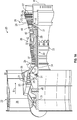
- the case hooks 218 are directed aftward (e.g., to the right in FIG. 2 ). Because of this, separation at the joint 224 and removal of the diffuser case 212a and/or the combustor 220 will not enable access to the BOAS 214 for maintenance, inspection, replacement, etc.
- first stage BOAS and/or other first stage components is achieved from an aft-end of the turbine case (e.g., case 212b) and may require all components aft of the BOAS 214 to be removed to gain access to the BOAS 214 to enable maintenance, inspection, replacement, etc.
- the case hooks face forward, rather than aft, as shown in FIG. 2 .
- the BOAS and/or the BOAS support may disengage from the case hooks, and thus improved access may be advantageous. That is, if the case hooks are forward facing, the BOAS and/or the BOAS support may not be adequately supported and/or retained within the case.
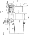
- FIGS. 3A to 3D various schematic illustrations of a BOAS retention member 326 in accordance with a non-limiting embodiment of the present disclosure are shown.
- FIG. 3A shows a cross-sectional illustration of the BOAS retention member 326 as installed in a turbine 300 of a gas turbine engine.
- FIG. 3B shows the turbine 300 in a disassembled state wherein the BOAS retention member 326 can be removed from the turbine 300.
- FIG. 3C is an isometric illustration of the BOAS retention member 326.
- FIG. 3D is a cross-sectional illustration of the BOAS retention member 326 as viewed along the line D-D in FIG. 3C .
- the BOAS retention member 326 is installed forward of a BOAS support 316 and BOAS 314.
- the case hooks 318 are forward facing which is preferable to enable easy maintenance including inspections and/or replacement of the BOAS 314.
- the BOAS retention member 326 is configured to support and retain the BOAS support 316 against the case hooks 318 and prevent the BOAS support 316 and/or the BOAS 314 to fall out of the turbine 300 during a maintenance operation.
- BOAS retention member 326 engages with the BOAS support 316
- BOAS retention member 326 engages with the BOAS support 316
- other configurations of the BOAS retention member 326 including embodiments that engage with the BOAS 314 or both the BOAS 314 and the BOAS support 316.
- a diffuser case 312a is separated and removed from the turbine case 312b.
- This provides access to the interior of the turbine 300 and an airfoil 301 can be removed (e.g., with removal of diffuser case 312a) to grant access to the BOAS 314 and the associated components.
- an airfoil 301 can be removed (e.g., with removal of diffuser case 312a) to grant access to the BOAS 314 and the associated components.
- additional components, parts, and/or features may be required to be removed from the forward side of the BOAS 314 to enable access thereto.
- the BOAS 314 With the forward components removed (e.g., diffuser case 312a, airfoil 301, etc.) the BOAS 314 can be accessed, as shown in FIG. 3B . As shown in FIG. 3B , even with the forward components removed, the BOAS retention member 326 engages with and retains the BOAS support 316 such that the BOAS support 316 and the BOAS 314 are held in place. The BOAS retention member 326 fixedly secures the BOAS support 316 in place due to an engagement with a portion of the turbine case 312b.
- the BOAS retention member 326 engages with and retains the BOAS support 316 such that the BOAS support 316 and the BOAS 314 are held in place.
- the BOAS retention member 326 fixedly secures the BOAS support 316 in place due to an engagement with a portion of the turbine case 312b.
- the engagement between the BOAS retention member 326 and the turbine case 312b may be by interference fit, snap fit, fastener, or other engagement means or mechanism.
- the BOAS retention member 326 includes a retention element 328 that is configured to engage with a case land 330.
- the retention element 328 and the case land 330 are configured to form an interference fit.
- the interference fit is achieved because an exterior diameter of the BOAS retention member 326 is greater than an interior diameter of the turbine case 312b at the case land 330.
- the retention element of the retention member can be a fastener such as a screw, bolt, snap feature, latch feature, etc.
- a support element 332 of the BOAS retention member 326 engages with a forward surface 334 of the BOAS support 316. Further, as shown, the BOAS retention member 326 includes a seal surface 336 that is configured to engage with a seal 338.
- the BOAS retention member 326 includes a removal element 340.
- the removal element 340 is configured to enable a tool or user's hand to pull the BOAS retention member 326 out of engagement with the turbine case 312b.
- the removal element 340 is optional, and other means or mechanisms for removing the BOAS retention member 326 from engagement with the turbine case 312b are possible without departing from the scope of the present disclosure.
- the BOAS retention member 326 is a unitary or continuous annular body formed in the shape of a ring.
- the BOAS retention member 326 can be manufactured by additive manufacturing, forging, machining, drawing, or other process.
- the BOAS retention member 326 in some non-limiting embodiments, is formed from a metal or metallic alloy that is selected to provide flexibility in order to enable an interference fit with a case of a gas turbine engine and also to withstand high temperatures during a life of the BOAS retention member.
- the BOAS retention member 326 is shown in cross-section and separate from a gas turbine engine.
- the BOAS retention member 326 is defined by a body 342 having a first, exterior side 344 and a second, interior side 346.
- the first, exterior side 344 includes the retention element 328 configured to engage with a case of a gas turbine engine.
- the retention element 328 is a portion of the BOAS retention member 326 that extends outward from the first side 342.
- the second, interior side 346 includes the optional removal element 340.
- the retention element is located at a first end 348 of the body 342.
- the body 342 includes the support element 332 at a second end 350 thereof.
- FIG. 4 a flow process for performing maintenance on a gas turbine engine in accordance with an embodiment of the present disclosure is shown.
- the flow process 400 can be employed using a BOAS retention member similar to that described above and/or variations thereon.
- a BOAS of interest is located near a joint between two sections of case of the gas turbine engine.
- the orientation will be similar to that shown in FIGS. 3A to 3D , wherein case hooks that support a BOAS support are forward facing.
- flow process 400 can be used for BOAS or other elements of interest that may require support by a retention member.
- a forward case is removed from the gas turbine engine.
- the forward case is a section of case that is forward of a location having a BOAS that requires inspection and/or maintenance. With the forward case removed, interior components and parts of the gas turbine engine are exposed and accessible.
- components that are forward of the BOAS of interest are removed from the engine (e.g., compare FIG. 3A and FIG. 3B ). Removal of the forward components exposes the BOAS, a BOAS support, and the BOAS retention member (e.g., as described above).
- the BOAS retention member is disengaged from the case, thus enabling access to and removal of the BOAS and/or BOAS support.
- the disengagement may be achieved by using a tool or even manually pulling on a removal element of the BOAS retention member.
- a fastener that joins the BOAS retention member to the case of the gas turbine engine can be removed for disengagement of the BOAS retention member.
- maintenance is performed on the BOAS and/or BOAS support.
- maintenance can include inspection of the BOAS and/or BOAS support, and if required, the BOAS and/or BOAS can be removed from the gas turbine engine.
- the BOAS and/or BOAS support can be replaced during the maintenance operation.
- the BOAS retention member can be replaced and engaged with a case of the gas turbine engine, as shown at block 410.
- the forward components can be reinstalled into the gas turbine engine, as shown at block 412. Finally, the forward case can be replaced and engaged at a joint, as shown at block 414.
- embodiments described herein provide a retention member that enables easy access to a blade outer air seal and/or blade outer air seal support in a gas turbine engine. Further, advantageously, embodiments provided herein enable the use of forward facing or oriented case hooks on case elements of a gas turbine engine such that easy removal, replacement, and/or inspection of BOAS is enabled. Further, embodiments provided herein can provide significant savings in weight, cost, and/or part count by eliminating the need for additional components to support a BOAS and/or BOAS support. For example, flange bolt holes can be structurally limiting features because they introduce stress concentrations, and embodiments provided herein eliminate such bolt holes thus improving fatigue life in turbine cases, diffuser cases, BOAS supports, and other components. Further, embodiments provided herein have a relatively simple geometry, as compared to configurations having additional flanges, bolts, etc.
Description
- The subject matter disclosed herein generally relates to blade outer air seals in gas turbine engines and, more particularly, to retention members for blade outer air seals.
- In gas turbine engines, the first stage Blade Outer Air Seals (BOAS) and Blade Outer Air Seal Supports (BOAS supports) are often attached to hooks on the High Pressure Turbine (HPT) case. These hooks can either face aft or forward and depending on the direction of the hooks, the BOAS and BOAS support will need to be assembled from the aft side or from the forward side of the gas turbine engine, respectively. It is beneficial to have the BOAS and BOAS supports FWD (forwardly) removable for engine maintainability.
- If the BOAS and BOAS supports, often lower life components, are accessible from the front they can be easily accessible by simply separating the HPT module from a diffuser module of the gas turbine engine. The alternative is coming from the rear and having to disassemble and remove all components aft of the first stage BOAS and BOAS supports to get to the first stage BOAS and BOAS supports.
- During maintenance operations, the gas turbine engine is often oriented forward face down and the HPT case is pulled upward, requiring the BOAS and BOAS supports to be retained and secured such that gravity cannot disengage these elements during disassembly and/or maintenance operations. In order to prevent the first stage BOAS and BOAS supports from falling out after separating a HPT case flange from a diffuser module case flange there is often a bolted flange. The bolted flange is either separate from the HPT/diffuser flange or is included with the flanges thus making it a triple flange. The flange is integral to a component that retains the first stage BOAS and BOAS supports and this component remains with the HPT after separation of the HPT-diffuser flange. This technique is effective, but it requires a flanged component, and often additional bolts, which adds significant weight, cost, and part count to the gas turbine engine.
-
EP 1577506 A1 ,US2015/226124 ,EP 1079076 A2 andWO 2014/163674 A1 disclose retention members, shroud carriers and support rings which are fastened to a turbine casing or another support.EP 1225309 A1 discloses a support spacer sector having a tab at an upstream end which is supported on the inside wall of a turbine casing. - Viewed from one aspect the present invention provides a gas turbine engine according to claim 1.
- Viewed from another aspect the present invention provides a method of performing a maintenance operation on a gas turbine engine according to claim 6.
- A retention member for a component of a gas turbine engine is disclosed. The retention member includes an annular body having a first side, a second side, a first end, and a second end, a retention element configured at the first end of the annular body and on the first side, the retention element configured to releasably engage with an interior surface of a case of the gas turbine engine, and a support element configured at the second end of the annular body, the support element configured to engage with a surface of at least one of a blade outer air seal or a blade outer air seal support.
- The retention member may include a seal surface configured to engage with a seal to provide fluid sealing between the annular body and at least one of the interior surface of the case, the blade outer air seal, or the blade outer air seal support.
- The retention member may include a removal element configured to enable manual removal of the retention member from engagement with the interior surface of the case.
- In some disclosed arrangements of the retention member the annular body, the retention element, and the support element are a formed of a unitary body.
- The retention element is configured such that, when engaged in a gas turbine engine, the retention element forms an interference fit with a portion of the case of the gas turbine engine.
- A gas turbine engine is disclosed having a case having case hooks on an interior surface of the case, a blade outer air seal supported by the case hooks, and a retention member. The retention member includes an annular body having a first side, a second side, a first end, and a second end, a retention element configured at the first end of the annular body and on the first side, the retention element configured to releasably engage with the interior surface of the case, and a support element configured at the second end of the annular body, the support element configured to engage with a surface of at least one of the blade outer air seal.
- The retention member may include a seal surface configured to engage with a seal to provide fluid sealing between the annular body and at least one of the interior surface of the case and the blade outer air seal.
- The retention member may include a removal element configured to enable manual removal of the retention member from engagement with the interior surface of the case.
- The annular body, the retention element, and the support element may be formed of a unitary body.
- In disclosed arrangements of the gas turbine engine the case hooks are forward facing case hooks.
- The retention element is configured such that, when engaged in the gas turbine engine, the retention element forms an interference fit with a portion of the case of the gas turbine engine.
- In disclosed arrangements the blade outer air seal support is configured between the case hooks and the blade outer air seal, the blade outer air seal support configured to engage with the case hooks and support the blade outer air seal, the support element configured to engage with at least one of the blade outer air seal or the blade outer air seal support.
- The gas turbine engine may include a case land on the interior surface of the case, wherein the retention element is configured to engage with the case land in an interference fit.
- A method of performing a maintenance operation on a gas turbine engine is also disclosed. The method includes removing a first portion of a case of the gas turbine engine; removing components of the gas turbine engine housed within a second portion of the case to expose a blade outer air seal, a blade outer air seal support, and a retention member, the retention member having an annular body with a first side, a second side, a first end, and a second end, a retention element configured at the first end of the annular body and on the first side, the retention element configured to releasably engage with an interior surface of the second portion of the case, and a support element configured at the second end of the annular body, the support element configured to engage with a surface of at least one of the blade outer air seal or the blade outer air seal support; disengaging the retention member from engagement with the inner surface of the second portion of the case; and performing a maintenance operation on at least one of the blade outer air seal or the blade outer air seal support.
- In addition to one or more of the features described above, further embodiments of the method may include, after performing the maintenance operation, re-engaging the retention member with the interior surface of the second portion of the case to retain at least one of the blade outer air seal and the blade outer air seal support within the second portion of the case.
- In addition to one or more of the features described above, further embodiments of the method may include that the maintenance operation comprises replacing/repairing the blade outer air seal.
- In addition to one or more of the features described above, or as an alternative, in further embodiments of the method the process is performed from a forward portion of the gas turbine engine, and the blade outer air seal support is engaged with forward facing case hooks.
- In addition to one or more of the features described above, or as an alternative, in further embodiments of the method disengaging the retention member comprises applying force to a removal element of the retention member.
- In the disclosed embodiments of the method the retention member is engaged with the interior surface of the second portion of the case by an interference fit.
- Technical effects of embodiments of the present disclosure include a retention member for components of a gas turbine engine that is configured to retain or support the components during a maintenance operation performed on the gas turbine engine. Further technical effects include reducing the weight and/or footprint of mechanism for retaining components, such as blade outer air seals, within gas turbine engines.
- The foregoing features and elements may be executed or utilized in various combinations without exclusivity, unless expressly indicated otherwise. These features and elements as well as the operation thereof will become more apparent in light of the following description and the accompanying drawings. It should be understood, however, that the following description and drawings are intended to be illustrative and explanatory in nature and non-limiting.
- The subject matter is particularly pointed out and distinctly claimed at the conclusion of the specification. The foregoing and other features and advantages of the present disclosure are apparent from the following detailed description taken in conjunction with the accompanying drawings in which:
-
FIG. 1A is a schematic cross-sectional illustration of a gas turbine engine that may employ various embodiments disclosed herein; -
FIG. 1B is a schematic illustration of a turbine that may employ various embodiments disclosed herein; -
FIG. 2 is a schematic illustration of a portion of a gas turbine engine having a blade outer air seal support engaged with aftward facing case hooks; -
FIG. 3A is a schematic illustration of a portion of a gas turbine engine having a blade outer air seal support engaged with forward facing case hooks and retained by a retention member in accordance with an embodiment of the present disclosure; -
FIG. 3B is a schematic illustration of the gas turbine engine ofFIG. 3A in a partially disassembled state; -
FIG. 3C is an isometric schematic illustration of the retention member ofFIG. 3A in accordance with an embodiment of the present disclosure; -
FIG. 3D is a cross-section schematic illustration of the retention member ofFIG. 3C as viewed along the line D-D; and -
FIG. 4 is a flow process of performing a maintenance operation on a gas turbine engine in accordance with an embodiment of the present disclosure. - As shown and described herein, various features of the disclosure will be presented. Various embodiments may have the same or similar features and thus the same or similar features may be labelled with the same reference numeral, but preceded by a different first number indicating the Figure Number to which the feature is shown. Thus, for example, element "a" that is shown in FIG. X may be labelled "Xa" and a similar feature in FIG. Z may be labelled "Za". Although similar reference numbers may be used in a generic sense, various embodiments will be described and various features may include changes, alterations, modifications, etc. as will be appreciated by those of skill in the art, whether explicitly described or otherwise would be appreciated by those of skill in the art.
-
FIG. 1A schematically illustrates agas turbine engine 20. The exemplarygas turbine engine 20 is a two-spool turbofan engine that generally incorporates afan section 22, acompressor section 24, acombustor section 26, and aturbine section 28. Alternative engines might include an augmenter section (not shown) among other systems for features. Thefan section 22 drives air along a bypass flow path B, while thecompressor section 24 drives air along a core flow path C for compression and communication into thecombustor section 26. Hot combustion gases generated in thecombustor section 26 are expanded through theturbine section 28. Although depicted as a turbofan gas turbine engine in the disclosed non-limiting embodiment, it should be understood that the concepts described herein are not limited to turbofan engines and these teachings could extend to other types of engines, including but not limited to, three-spool engine architectures. - The
gas turbine engine 20 generally includes alow speed spool 30 and a high speed spool 32 mounted for rotation about an engine centreline longitudinal axis A. Thelow speed spool 30 and the high speed spool 32 may be mounted relative to an enginestatic structure 33 viaseveral bearing systems 31. It should be understood that other bearingsystems 31 may alternatively or additionally be provided. - The
low speed spool 30 generally includes aninner shaft 34 that interconnects afan 36, alow pressure compressor 38 and a low pressure turbine 39. Theinner shaft 34 can be connected to thefan 36 through a gearedarchitecture 45 to drive thefan 36 at a lower speed than thelow speed spool 30. The high speed spool 32 includes anouter shaft 35 that interconnects ahigh pressure compressor 37 and ahigh pressure turbine 40. In this embodiment, theinner shaft 34 and theouter shaft 35 are supported at various axial locations by bearingsystems 31 positioned within the enginestatic structure 33. - A combustor 42 is arranged between the
high pressure compressor 37 and thehigh pressure turbine 40. Amid-turbine frame 44 may be arranged generally between thehigh pressure turbine 40 and the low pressure turbine 39. Themid-turbine frame 44 can support one ormore bearing systems 31 of theturbine section 28. Themid-turbine frame 44 may include one ormore airfoils 46 that extend within the core flow path C. - The
inner shaft 34 and theouter shaft 35 are concentric and rotate via the bearingsystems 31 about the engine centreline longitudinal axis A, which is colinear with their longitudinal axes. The core airflow is compressed by thelow pressure compressor 38 and thehigh pressure compressor 37, is mixed with fuel and burned in the combustor 42, and is then expanded over thehigh pressure turbine 40 and the low pressure turbine 39. Thehigh pressure turbine 40 and the low pressure turbine 39 rotationally drive the respective high speed spool 32 and thelow speed spool 30 in response to the expansion. - The pressure ratio of the low pressure turbine 39 can be pressure measured prior to the inlet of the low pressure turbine 39 as related to the pressure at the outlet of the low pressure turbine 39 and prior to an exhaust nozzle of the
gas turbine engine 20. In one non-limiting embodiment, the bypass ratio of thegas turbine engine 20 is greater than about ten (10:1), the fan diameter is significantly larger than that of thelow pressure compressor 38, and the low pressure turbine 39 has a pressure ratio that is greater than about five (5:1). It should be understood, however, that the above parameters are only examples of one embodiment of a geared architecture engine and that the present disclosure is applicable to other gas turbine engines, including direct drive turbofans. - In this embodiment of the example
gas turbine engine 20, a significant amount of thrust is provided by the bypass flow path B due to the high bypass ratio. Thefan section 22 of thegas turbine engine 20 is designed for a particular flight condition - typically cruise at about 0.8 Mach and about 35,000 feet (about 10,700 m). This flight condition, with thegas turbine engine 20 at its best fuel consumption, is also known as bucket cruise Thrust Specific Fuel Consumption (TSFC). TSFC is an industry standard parameter of fuel consumption per unit of thrust. - Fan Pressure Ratio is the pressure ratio across a blade of the
fan section 22 without the use of a Fan Exit Guide Vane system. The low Fan Pressure Ratio according to one non-limiting embodiment of the examplegas turbine engine 20 is less than 1.45. Low Corrected Fan Tip Speed is the actual fan tip speed divided by an industry standard temperature correction of [(Tram ° R)/(518.7° R)]0.5, where T represents the ambient temperature in degrees Rankine. The Low Corrected Fan Tip Speed according to one non-limiting embodiment of the examplegas turbine engine 20 is less than about 1150 fps (about 350 m/s). - Each of the
compressor section 24 and theturbine section 28 may include alternating rows of rotor assemblies and vane assemblies (shown schematically) that carry airfoils that extend into the core flow path C. For example, the rotor assemblies can carry a plurality ofrotating blades 25, while each vane assembly can carry a plurality ofvanes 27 that extend into the core flow path C. Theblades 25 of the rotor assemblies create or extract energy (in the form of pressure) from the core airflow that is communicated through thegas turbine engine 20 along the core flow path C. Thevanes 27 of the vane assemblies direct the core airflow to theblades 25 to either add or extract energy. - Various components of a
gas turbine engine 20, including but not limited to the airfoils of theblades 25 and thevanes 27 of thecompressor section 24 and theturbine section 28, may be subjected to repetitive thermal cycling under widely ranging temperatures and pressures. The hardware of theturbine section 28 is particularly subjected to relatively extreme operating conditions. Therefore, some components may require internal cooling circuits for cooling the parts during engine operation. Example cooling circuits that include features such as airflow bleed ports are discussed below. -
FIG. 1B is a schematic view of a turbine section that may employ various embodiments disclosed herein.Turbine 100 includes a plurality of airfoils, including, for example, one ormore blades 101 andvanes 102. Theairfoils inner diameter 106 to anouter diameter 108, or vice versa. The airfoil cavities may be separated by partitions within theairfoils inner diameter 106 or theouter diameter 108 of theairfoil airfoil airfoil respective airfoil blades 101 and the vanes may includeplatforms 110 located proximal to the inner diameter thereof. Located below theplatforms 110 may be airflow ports and/or bleed orifices that enable air to bleed from the internal cavities of theairfoils platform 110. - The
turbine 100 is housed within acase 112, which may have multiple parts (e.g., turbine case, diffuser case, etc.). In various locations, components, such as seals, may be positioned betweenairfoils case 112. For example, as shown inFIG. 1B , blade outer air seals 114 (hereafter "BOAS") are located radially outward from theblades 101. As will be appreciated by those of skill in the art, theBOAS 114 can include BOAS supports (see, e.g.,FIG. 2 ) that are configured to fixedly connect or attach theBOAS 114 to thecase 112. As shown inFIG. 1B , thecase 112 includes a plurality ofhooks 118 that engage with thehooks 116 to secure theBOAS 114 between thecase 112 and a tip of theblade 101. - In traditional gas turbine engine configurations, a first stage BOAS is directly aft of a combustor and is exposed to high temperatures expelled therefrom. Accordingly, the first stage BOAS can be a life limiting part of the gas turbine engine and may require replacement more often than surrounding parts (or other parts in the gas turbine engine). Replacing the first stage BOAS can be difficult and/or expensive due to the placement within the gas turbine engine and the steps required to remove the case surrounding the turbine section and providing access to the BOAS. Accordingly, enabling easy or efficient access to BOAS can decrease maintenance costs and/or reduce maintenance times.
- For example, turning to
FIG. 2 , a schematic illustration of a portion of aturbine 200 is shown. Theturbine 200 includes acombustor 220 housed within adiffuser case 212a. Aft of thecombustor 220 is aturbine section 222 such as a high pressure turbine. Theturbine section 222 includes a plurality ofairfoils turbine case 212b. Thediffuser case 212a and theturbine case 212b are fixedly connected at a joint 224 and form a portion of a case that houses a gas turbine engine. - The
turbine case 212b includes one ormore hooks 218 extending radially inward from an inner surface thereof that are configured to receive components of theturbine 200. For example, one or more case hooks 218 can receive aBOAS support 216 that is located radially outward from ablade 202. TheBOAS support 216 supports aBOAS 214 that is located between theBOAS support 216 and a tip of theblade 202. As shown, the case hooks 218 are directed aftward (e.g., to the right inFIG. 2 ). Because of this, separation at the joint 224 and removal of thediffuser case 212a and/or thecombustor 220 will not enable access to theBOAS 214 for maintenance, inspection, replacement, etc. Instead, access to a first stage BOAS and/or other first stage components is achieved from an aft-end of the turbine case (e.g.,case 212b) and may require all components aft of theBOAS 214 to be removed to gain access to theBOAS 214 to enable maintenance, inspection, replacement, etc. - In view of the above, it may be advantageous to have the case hooks face forward, rather than aft, as shown in
FIG. 2 . For example, with forward facing hooks, during a maintenance operation, the BOAS and/or the BOAS support may disengage from the case hooks, and thus improved access may be advantageous. That is, if the case hooks are forward facing, the BOAS and/or the BOAS support may not be adequately supported and/or retained within the case. - Some solutions to this problem have included bolted supports which require a triple flange (e.g., joint 224 is a double flange). The additional flange would support the BOAS support and/or the BOAS from the forward side. However, increasing the number of flanges is not efficient due to the increased weight imparted by the additional flange. Another solution incorporates a bolt into the BOAS support. By bolting the BOAS, an additional flange is added, and thus the same problem arises. Accordingly, it is desirable to have a support element engage with the BOAS and/or BOAS support such that forward facing case hooks may be used, thus lowering maintenance costs on gas turbine engines.
- Turning now to
FIGS. 3A to 3D , various schematic illustrations of aBOAS retention member 326 in accordance with a non-limiting embodiment of the present disclosure are shown.FIG. 3A shows a cross-sectional illustration of theBOAS retention member 326 as installed in aturbine 300 of a gas turbine engine.FIG. 3B shows theturbine 300 in a disassembled state wherein theBOAS retention member 326 can be removed from theturbine 300.FIG. 3C is an isometric illustration of theBOAS retention member 326.FIG. 3D is a cross-sectional illustration of theBOAS retention member 326 as viewed along the line D-D inFIG. 3C . - In
FIGS. 3A and3B , forward is to the left on the page and aftward is to the right on the page. As shown, theBOAS retention member 326 is installed forward of aBOAS support 316 andBOAS 314. In comparison to the embodiments described above, the case hooks 318 are forward facing which is preferable to enable easy maintenance including inspections and/or replacement of theBOAS 314. As shown, theBOAS retention member 326 is configured to support and retain theBOAS support 316 against the case hooks 318 and prevent theBOAS support 316 and/or theBOAS 314 to fall out of theturbine 300 during a maintenance operation. Although shown with theBOAS retention member 326 engaged with theBOAS support 316, those of skill in the art will appreciate that other configurations of theBOAS retention member 326 are possible, including embodiments that engage with theBOAS 314 or both theBOAS 314 and theBOAS support 316. - During a maintenance operation, fasteners are removed from a joint 324 and a
diffuser case 312a is separated and removed from theturbine case 312b. This provides access to the interior of theturbine 300 and anairfoil 301 can be removed (e.g., with removal ofdiffuser case 312a) to grant access to theBOAS 314 and the associated components. Those of skill in the art will appreciate that additional components, parts, and/or features may be required to be removed from the forward side of theBOAS 314 to enable access thereto. - With the forward components removed (e.g.,
diffuser case 312a,airfoil 301, etc.) theBOAS 314 can be accessed, as shown inFIG. 3B . As shown inFIG. 3B , even with the forward components removed, theBOAS retention member 326 engages with and retains theBOAS support 316 such that theBOAS support 316 and theBOAS 314 are held in place. TheBOAS retention member 326 fixedly secures theBOAS support 316 in place due to an engagement with a portion of theturbine case 312b. - The engagement between the
BOAS retention member 326 and theturbine case 312b may be by interference fit, snap fit, fastener, or other engagement means or mechanism. For example, as shown inFIGS. 3A and3B , theBOAS retention member 326 includes aretention element 328 that is configured to engage with acase land 330. In the embodiment ofFIGS. 3A and3B , theretention element 328 and thecase land 330 are configured to form an interference fit. The interference fit is achieved because an exterior diameter of theBOAS retention member 326 is greater than an interior diameter of theturbine case 312b at thecase land 330. In some embodiments, the retention element of the retention member can be a fastener such as a screw, bolt, snap feature, latch feature, etc. - A
support element 332 of theBOAS retention member 326 engages with aforward surface 334 of theBOAS support 316. Further, as shown, theBOAS retention member 326 includes aseal surface 336 that is configured to engage with a seal 338. - To remove the
BOAS retention member 326 from engagement with theturbine case 312b, theBOAS retention member 326 includes aremoval element 340. Theremoval element 340 is configured to enable a tool or user's hand to pull theBOAS retention member 326 out of engagement with theturbine case 312b. Those of skill in the art will appreciate that theremoval element 340 is optional, and other means or mechanisms for removing theBOAS retention member 326 from engagement with theturbine case 312b are possible without departing from the scope of the present disclosure. - As shown in
FIG. 3C , theBOAS retention member 326 is a unitary or continuous annular body formed in the shape of a ring. TheBOAS retention member 326 can be manufactured by additive manufacturing, forging, machining, drawing, or other process. TheBOAS retention member 326, in some non-limiting embodiments, is formed from a metal or metallic alloy that is selected to provide flexibility in order to enable an interference fit with a case of a gas turbine engine and also to withstand high temperatures during a life of the BOAS retention member. - Turning to
FIG. 3D , theBOAS retention member 326 is shown in cross-section and separate from a gas turbine engine. TheBOAS retention member 326 is defined by abody 342 having a first,exterior side 344 and a second,interior side 346. The first,exterior side 344 includes theretention element 328 configured to engage with a case of a gas turbine engine. In some embodiments, theretention element 328 is a portion of theBOAS retention member 326 that extends outward from thefirst side 342. The second,interior side 346 includes theoptional removal element 340. As shown, the retention element is located at a first end 348 of thebody 342. Further, thebody 342 includes thesupport element 332 at asecond end 350 thereof. - Turning now to
FIG. 4 , a flow process for performing maintenance on a gas turbine engine in accordance with an embodiment of the present disclosure is shown. Theflow process 400 can be employed using a BOAS retention member similar to that described above and/or variations thereon. In the embodiment offlow process 400, a BOAS of interest is located near a joint between two sections of case of the gas turbine engine. For simplicity, the orientation will be similar to that shown inFIGS. 3A to 3D , wherein case hooks that support a BOAS support are forward facing. However, those of skill in the art will appreciate thatflow process 400 can be used for BOAS or other elements of interest that may require support by a retention member. - At
block 402, a forward case is removed from the gas turbine engine. The forward case is a section of case that is forward of a location having a BOAS that requires inspection and/or maintenance. With the forward case removed, interior components and parts of the gas turbine engine are exposed and accessible. For example, atblock 404, components that are forward of the BOAS of interest are removed from the engine (e.g., compareFIG. 3A andFIG. 3B ). Removal of the forward components exposes the BOAS, a BOAS support, and the BOAS retention member (e.g., as described above). Atblock 406, the BOAS retention member is disengaged from the case, thus enabling access to and removal of the BOAS and/or BOAS support. The disengagement may be achieved by using a tool or even manually pulling on a removal element of the BOAS retention member. In other embodiments, a fastener that joins the BOAS retention member to the case of the gas turbine engine can be removed for disengagement of the BOAS retention member. - At
block 408, maintenance is performed on the BOAS and/or BOAS support. For example, maintenance can include inspection of the BOAS and/or BOAS support, and if required, the BOAS and/or BOAS can be removed from the gas turbine engine. The BOAS and/or BOAS support can be replaced during the maintenance operation. After the maintenance operation is completed, the BOAS retention member can be replaced and engaged with a case of the gas turbine engine, as shown atblock 410. After the BOAS retention member is secured and supports and retains the BOAS and/or BOAS support, the forward components can be reinstalled into the gas turbine engine, as shown atblock 412. Finally, the forward case can be replaced and engaged at a joint, as shown atblock 414. - Those of skill in the art will appreciate that the above described process is illustrative and non-limiting and variations thereon are contemplated herein. For example, various of the steps of
flow process 400 can be optional, omitted, and/or performed in a different order. Further, additional steps and/or processes can be performed without departing from the scope of the present disclosure. Moreover, although described with respect to forward facing hooks and forward access and removal of the BOAS and/or BOAS support, those of skill in the art will appreciate that theflow process 400 can be performed from an aft side in cases where the part of interest is located closer to an aft flange, and thus provide easy and efficient access to elements/components that are supported and engaged with aftward facing case hooks. - Advantageously, embodiments described herein provide a retention member that enables easy access to a blade outer air seal and/or blade outer air seal support in a gas turbine engine. Further, advantageously, embodiments provided herein enable the use of forward facing or oriented case hooks on case elements of a gas turbine engine such that easy removal, replacement, and/or inspection of BOAS is enabled. Further, embodiments provided herein can provide significant savings in weight, cost, and/or part count by eliminating the need for additional components to support a BOAS and/or BOAS support. For example, flange bolt holes can be structurally limiting features because they introduce stress concentrations, and embodiments provided herein eliminate such bolt holes thus improving fatigue life in turbine cases, diffuser cases, BOAS supports, and other components. Further, embodiments provided herein have a relatively simple geometry, as compared to configurations having additional flanges, bolts, etc.
- The use of the terms "a", "an", "the", and similar references in the context of description (especially in the context of the following claims) are to be construed to cover both the singular and the plural, unless otherwise indicated herein or specifically contradicted by context. The modifier "about" used in connection with a quantity is inclusive of the stated value and has the meaning dictated by the context (e.g., it includes the degree of error associated with measurement of the particular quantity). All ranges disclosed herein are inclusive of the endpoints, and the endpoints are independently combinable with each other.
- While the present disclosure has been described in detail in connection with only a limited number of embodiments, it should be readily understood that the present disclosure is not limited to such disclosed embodiments. Additionally, while various embodiments of the present disclosure have been described, it is to be understood that aspects of the present disclosure may include only some of the described embodiments.
- For example, although an aero or aircraft engine application is shown and described above, those of skill in the art will appreciate that airfoil configurations as described herein may be applied to industrial applications and/or industrial gas turbine engines, land based or otherwise. Further, although shown and described herein with respect forward facing case hooks, those of skill in the art will appreciate that aftward facing case hooks and appropriately configured BOAS and/or BOAS supports can employ embodiments of the present disclosure. Moreover, although shown and described with respect to a particular BOAS, those of skill in the art that retention members as shown and described herein may be used to retain any component within a gas turbine engine, including but not limited to, compressor BOAS and/or compressor BOAS supports.
- Accordingly, the present disclosure is not to be seen as limited by the foregoing description, but is only limited by the scope of the appended claims.
Claims (10)
- A gas turbine engine comprising:a case (312b) having case hooks (318) on an interior surface of the case, wherein the case hooks (318) are forward facing case hooks;a blade outer air seal support (316) configured to engage with the case hooks (318);a blade outer air seal (314) supported by the blade outer air seal support (316); anda retention member (326) comprising:an annular body (342) having a first side (344), a second side (346), a first end (348), and a second end (350);a retention element (328) configured at the first end (348) of the annular body (342) and on the first side (344), the retention element (328) configured to releasably engage with the interior surface of the case (312b); anda support element (332) configured at the second end (350) of the annular body (342), the support element (332) configured to engage with a surface (334) of the blade outer air seal support (316) and retain the blade outer air seal support (316) within the case (312b);characterised in that the retention member (326) engages with the interior surface of the case (312b) by an interference fit.
- The gas turbine engine of claim 1, further comprising a seal surface (336) configured to engage with a seal (338) to provide fluid sealing between the annular body (342) and at least one of the interior surface of the case (312b), the blade outer air seal (314), or the blade outer air seal support (316).
- The gas turbine engine of any of the preceding claims, further comprising a removal element (340) configured to enable manual removal of the retention member (326) from engagement with the interior surface of the case (312b).
- The gas turbine engine of any of the preceding claims, wherein the annular body (342), the retention element (328), and the support element (332) are a formed of a unitary body.
- The gas turbine engine of any of the preceding claims, further comprising a case land (330) on the interior surface of the case (312b), wherein the interference fit engagement of the retention element (328) with the case (312b) is at the case land (330).
- A method of performing a maintenance operation on a gas turbine engine, the method comprising:removing a first portion (312a) of a case of the gas turbine engine;removing components of the gas turbine engine housed within a second portion (312b) of the case to expose a blade outer air seal (314), a blade outer air seal support (316), and a retention member (326), the retention member (326) having an annular body (342) with a first side (344), a second side (346), a first end (348), and a second end (350), a retention element (328) configured at the first end (348) of the annular body (342) and on the first side (344), the retention element (328) configured to releasably engage with an interior surface of the second portion (312b) of the case in an interference fit, and a support element (332) configured at the second end (350) of the annular body (342), the support element (342) configured to engage with a surface (334) of the blade outer air seal support (316) and retain the blade outer air seal support (316) within the case (312b);disengaging the retention member (326) from engagement with the inner surface of the second portion (312b) of the case; andperforming a maintenance operation on at least one of the blade outer air seal (314) or the blade outer air seal support (316).
- The method of claim 6, further comprising, after performing the maintenance operation, re-engaging the retention member (326) with the interior surface of the second portion (312b) of the case to retain the blade outer air seal support (316) within the second portion (312b) of the case.
- The method of any of claims 6 to 7, wherein the maintenance operation comprises replacing/repairing the blade outer air seal (314).
- The method of any of claims 6 to 8, wherein the process is performed from a forward portion of the gas turbine engine and wherein the blade outer air seal support (316) is engaged with forward facing case hooks (318).
- The method of any of claims 6 to 9, wherein disengaging the retention member (326) comprises applying force to a removal element (340) of the retention member (326).
Applications Claiming Priority (1)
| Application Number | Priority Date | Filing Date | Title |
|---|---|---|---|
| US15/099,755 US10436071B2 (en) | 2016-04-15 | 2016-04-15 | Blade outer air seal having retention snap ring |
Publications (2)
| Publication Number | Publication Date |
|---|---|
| EP3232009A1 EP3232009A1 (en) | 2017-10-18 |
| EP3232009B1 true EP3232009B1 (en) | 2020-06-17 |
Family
ID=58549052
Family Applications (1)
| Application Number | Title | Priority Date | Filing Date |
|---|---|---|---|
| EP17166781.9A Active EP3232009B1 (en) | 2016-04-15 | 2017-04-18 | Blade outer air seal having retention snap ring |
Country Status (2)
| Country | Link |
|---|---|
| US (1) | US10436071B2 (en) |
| EP (1) | EP3232009B1 (en) |
Families Citing this family (4)
| Publication number | Priority date | Publication date | Assignee | Title |
|---|---|---|---|---|
| FR3055147B1 (en) * | 2016-08-19 | 2020-05-29 | Safran Aircraft Engines | TURBINE RING ASSEMBLY |
| FR3055148B1 (en) * | 2016-08-19 | 2020-06-05 | Safran Aircraft Engines | TURBINE RING ASSEMBLY |
| FR3074518B1 (en) * | 2017-12-05 | 2020-01-03 | Safran Aircraft Engines | CONNECTION BETWEEN A CERAMIC MATRIX COMPOSITE DISTRIBUTOR AND A METAL SUPPORT OF A TURBOMACHINE TURBINE |
| US11578616B2 (en) | 2021-02-05 | 2023-02-14 | Pratt & Whitney Canada Corp. | Gas turbine engine assembly and method of disassembling same |
Family Cites Families (9)
| Publication number | Priority date | Publication date | Assignee | Title |
|---|---|---|---|---|
| US6435820B1 (en) | 1999-08-25 | 2002-08-20 | General Electric Company | Shroud assembly having C-clip retainer |
| FR2819010B1 (en) | 2001-01-04 | 2004-05-28 | Snecma Moteurs | STATOR RING SUPPORT AREA OF THE TURBINE HIGH PRESSURE TURBINE ROTATOR WITH A TURBOMACHINE |
| FR2867224B1 (en) | 2004-03-04 | 2006-05-19 | Snecma Moteurs | AXIAL AXIS HOLDING DEVICE FOR RING OF A TURBOMACHINE HIGH-PRESSURE TURBINE |
| US8365405B2 (en) * | 2008-08-27 | 2013-02-05 | United Technologies Corp. | Preforms and related methods for repairing abradable seals of gas turbine engines |
| US8998573B2 (en) * | 2010-10-29 | 2015-04-07 | General Electric Company | Resilient mounting apparatus for low-ductility turbine shroud |
| US20130019225A1 (en) * | 2011-07-11 | 2013-01-17 | Microsoft Corporation | Incremental Inferences for Developing Data Models |
| US20130004306A1 (en) * | 2011-06-30 | 2013-01-03 | General Electric Company | Chordal mounting arrangement for low-ductility turbine shroud |
| US9188062B2 (en) | 2012-08-30 | 2015-11-17 | Mitsubishi Hitachi Power Systems, Ltd. | Gas turbine |
| EP2971588A1 (en) | 2013-03-13 | 2016-01-20 | Rolls-Royce Corporation | Dovetail retention system for blade tracks |
-
2016
- 2016-04-15 US US15/099,755 patent/US10436071B2/en active Active
-
2017
- 2017-04-18 EP EP17166781.9A patent/EP3232009B1/en active Active
Non-Patent Citations (1)
| Title |
|---|
| None * |
Also Published As
| Publication number | Publication date |
|---|---|
| EP3232009A1 (en) | 2017-10-18 |
| US20170298776A1 (en) | 2017-10-19 |
| US10436071B2 (en) | 2019-10-08 |
Similar Documents
| Publication | Publication Date | Title |
|---|---|---|
| EP2900956B1 (en) | Gas turbine engine comprising a seal assembly for a static structure thereof | |
| EP2900961B1 (en) | Gas turbine engine airfoil cooling circuit | |
| US11035236B2 (en) | Baffle for a component of a gas turbine engine | |
| EP2971688B1 (en) | Gas turbine engine disclosing a heat shield and method of mounting this heat shield | |
| EP3415728B1 (en) | Gas turbine engine with rotating reversing compound gearbox | |
| EP3232009B1 (en) | Blade outer air seal having retention snap ring | |
| EP3231994B1 (en) | Axial flow compressor for a gas turbine engine | |
| WO2014123965A1 (en) | Low leakage multi-directional interface for a gas turbine engine | |
| EP2971677B1 (en) | Triple flange arrangement for a gas turbine engine | |
| EP2985421A1 (en) | Assembly, compressor and cooling system | |
| EP2885520B1 (en) | Component for a gas turbine engine and corresponding method of cooling | |
| US10584592B2 (en) | Platform for an airfoil having bowed sidewalls | |
| EP3047111B1 (en) | Component for a gas turbine engine, corresponding gas turbine engine and method of cooling | |
| US10544682B2 (en) | Expansion seals for airfoils | |
| EP3081748B1 (en) | Gas turbine engine system comprising a seal ring | |
| EP2927429B1 (en) | Gas turbine engine component with flow separating rib | |
| EP3098387B1 (en) | Installation fault tolerant damper | |
| EP3957824B1 (en) | Tandem rotor disk apparatus and corresponding gas turbine engine | |
| EP3011155B1 (en) | Heat shield | |
| EP3293361B1 (en) | Gas turbine engine and corresponding method of manufacturing | |
| US11111804B2 (en) | Inserts for slotted integrally bladed rotor |
Legal Events
| Date | Code | Title | Description |
|---|---|---|---|
| PUAI | Public reference made under article 153(3) epc to a published international application that has entered the european phase |
Free format text: ORIGINAL CODE: 0009012 |
|
| STAA | Information on the status of an ep patent application or granted ep patent |
Free format text: STATUS: THE APPLICATION HAS BEEN PUBLISHED |
|
| AK | Designated contracting states |
Kind code of ref document: A1 Designated state(s): AL AT BE BG CH CY CZ DE DK EE ES FI FR GB GR HR HU IE IS IT LI LT LU LV MC MK MT NL NO PL PT RO RS SE SI SK SM TR |
|
| AX | Request for extension of the european patent |
Extension state: BA ME |
|
| STAA | Information on the status of an ep patent application or granted ep patent |
Free format text: STATUS: REQUEST FOR EXAMINATION WAS MADE |
|
| 17P | Request for examination filed |
Effective date: 20180417 |
|
| RBV | Designated contracting states (corrected) |
Designated state(s): AL AT BE BG CH CY CZ DE DK EE ES FI FR GB GR HR HU IE IS IT LI LT LU LV MC MK MT NL NO PL PT RO RS SE SI SK SM TR |
|
| GRAP | Despatch of communication of intention to grant a patent |
Free format text: ORIGINAL CODE: EPIDOSNIGR1 |
|
| STAA | Information on the status of an ep patent application or granted ep patent |
Free format text: STATUS: GRANT OF PATENT IS INTENDED |
|
| INTG | Intention to grant announced |
Effective date: 20200113 |
|
| GRAS | Grant fee paid |
Free format text: ORIGINAL CODE: EPIDOSNIGR3 |
|
| GRAA | (expected) grant |
Free format text: ORIGINAL CODE: 0009210 |
|
| STAA | Information on the status of an ep patent application or granted ep patent |
Free format text: STATUS: THE PATENT HAS BEEN GRANTED |
|
| AK | Designated contracting states |
Kind code of ref document: B1 Designated state(s): AL AT BE BG CH CY CZ DE DK EE ES FI FR GB GR HR HU IE IS IT LI LT LU LV MC MK MT NL NO PL PT RO RS SE SI SK SM TR |
|
| REG | Reference to a national code |
Ref country code: GB Ref legal event code: FG4D |
|
| REG | Reference to a national code |
Ref country code: CH Ref legal event code: EP |
|
| REG | Reference to a national code |
Ref country code: DE Ref legal event code: R096 Ref document number: 602017018154 Country of ref document: DE |
|
| REG | Reference to a national code |
Ref country code: IE Ref legal event code: FG4D |
|
| REG | Reference to a national code |
Ref country code: AT Ref legal event code: REF Ref document number: 1281534 Country of ref document: AT Kind code of ref document: T Effective date: 20200715 |
|
| PG25 | Lapsed in a contracting state [announced via postgrant information from national office to epo] |
Ref country code: SE Free format text: LAPSE BECAUSE OF FAILURE TO SUBMIT A TRANSLATION OF THE DESCRIPTION OR TO PAY THE FEE WITHIN THE PRESCRIBED TIME-LIMIT Effective date: 20200617 Ref country code: NO Free format text: LAPSE BECAUSE OF FAILURE TO SUBMIT A TRANSLATION OF THE DESCRIPTION OR TO PAY THE FEE WITHIN THE PRESCRIBED TIME-LIMIT Effective date: 20200917 Ref country code: GR Free format text: LAPSE BECAUSE OF FAILURE TO SUBMIT A TRANSLATION OF THE DESCRIPTION OR TO PAY THE FEE WITHIN THE PRESCRIBED TIME-LIMIT Effective date: 20200918 Ref country code: LT Free format text: LAPSE BECAUSE OF FAILURE TO SUBMIT A TRANSLATION OF THE DESCRIPTION OR TO PAY THE FEE WITHIN THE PRESCRIBED TIME-LIMIT Effective date: 20200617 Ref country code: FI Free format text: LAPSE BECAUSE OF FAILURE TO SUBMIT A TRANSLATION OF THE DESCRIPTION OR TO PAY THE FEE WITHIN THE PRESCRIBED TIME-LIMIT Effective date: 20200617 |
|
| REG | Reference to a national code |
Ref country code: LT Ref legal event code: MG4D |
|
| REG | Reference to a national code |
Ref country code: NL Ref legal event code: MP Effective date: 20200617 |
|
| PG25 | Lapsed in a contracting state [announced via postgrant information from national office to epo] |
Ref country code: HR Free format text: LAPSE BECAUSE OF FAILURE TO SUBMIT A TRANSLATION OF THE DESCRIPTION OR TO PAY THE FEE WITHIN THE PRESCRIBED TIME-LIMIT Effective date: 20200617 Ref country code: RS Free format text: LAPSE BECAUSE OF FAILURE TO SUBMIT A TRANSLATION OF THE DESCRIPTION OR TO PAY THE FEE WITHIN THE PRESCRIBED TIME-LIMIT Effective date: 20200617 Ref country code: LV Free format text: LAPSE BECAUSE OF FAILURE TO SUBMIT A TRANSLATION OF THE DESCRIPTION OR TO PAY THE FEE WITHIN THE PRESCRIBED TIME-LIMIT Effective date: 20200617 Ref country code: BG Free format text: LAPSE BECAUSE OF FAILURE TO SUBMIT A TRANSLATION OF THE DESCRIPTION OR TO PAY THE FEE WITHIN THE PRESCRIBED TIME-LIMIT Effective date: 20200917 |
|
| REG | Reference to a national code |
Ref country code: AT Ref legal event code: MK05 Ref document number: 1281534 Country of ref document: AT Kind code of ref document: T Effective date: 20200617 |
|
| PG25 | Lapsed in a contracting state [announced via postgrant information from national office to epo] |
Ref country code: AL Free format text: LAPSE BECAUSE OF FAILURE TO SUBMIT A TRANSLATION OF THE DESCRIPTION OR TO PAY THE FEE WITHIN THE PRESCRIBED TIME-LIMIT Effective date: 20200617 Ref country code: NL Free format text: LAPSE BECAUSE OF FAILURE TO SUBMIT A TRANSLATION OF THE DESCRIPTION OR TO PAY THE FEE WITHIN THE PRESCRIBED TIME-LIMIT Effective date: 20200617 |
|
| PG25 | Lapsed in a contracting state [announced via postgrant information from national office to epo] |
Ref country code: EE Free format text: LAPSE BECAUSE OF FAILURE TO SUBMIT A TRANSLATION OF THE DESCRIPTION OR TO PAY THE FEE WITHIN THE PRESCRIBED TIME-LIMIT Effective date: 20200617 Ref country code: SM Free format text: LAPSE BECAUSE OF FAILURE TO SUBMIT A TRANSLATION OF THE DESCRIPTION OR TO PAY THE FEE WITHIN THE PRESCRIBED TIME-LIMIT Effective date: 20200617 Ref country code: PT Free format text: LAPSE BECAUSE OF FAILURE TO SUBMIT A TRANSLATION OF THE DESCRIPTION OR TO PAY THE FEE WITHIN THE PRESCRIBED TIME-LIMIT Effective date: 20201019 Ref country code: CZ Free format text: LAPSE BECAUSE OF FAILURE TO SUBMIT A TRANSLATION OF THE DESCRIPTION OR TO PAY THE FEE WITHIN THE PRESCRIBED TIME-LIMIT Effective date: 20200617 Ref country code: ES Free format text: LAPSE BECAUSE OF FAILURE TO SUBMIT A TRANSLATION OF THE DESCRIPTION OR TO PAY THE FEE WITHIN THE PRESCRIBED TIME-LIMIT Effective date: 20200617 Ref country code: IT Free format text: LAPSE BECAUSE OF FAILURE TO SUBMIT A TRANSLATION OF THE DESCRIPTION OR TO PAY THE FEE WITHIN THE PRESCRIBED TIME-LIMIT Effective date: 20200617 Ref country code: RO Free format text: LAPSE BECAUSE OF FAILURE TO SUBMIT A TRANSLATION OF THE DESCRIPTION OR TO PAY THE FEE WITHIN THE PRESCRIBED TIME-LIMIT Effective date: 20200617 Ref country code: AT Free format text: LAPSE BECAUSE OF FAILURE TO SUBMIT A TRANSLATION OF THE DESCRIPTION OR TO PAY THE FEE WITHIN THE PRESCRIBED TIME-LIMIT Effective date: 20200617 |
|
| PG25 | Lapsed in a contracting state [announced via postgrant information from national office to epo] |
Ref country code: PL Free format text: LAPSE BECAUSE OF FAILURE TO SUBMIT A TRANSLATION OF THE DESCRIPTION OR TO PAY THE FEE WITHIN THE PRESCRIBED TIME-LIMIT Effective date: 20200617 Ref country code: SK Free format text: LAPSE BECAUSE OF FAILURE TO SUBMIT A TRANSLATION OF THE DESCRIPTION OR TO PAY THE FEE WITHIN THE PRESCRIBED TIME-LIMIT Effective date: 20200617 Ref country code: IS Free format text: LAPSE BECAUSE OF FAILURE TO SUBMIT A TRANSLATION OF THE DESCRIPTION OR TO PAY THE FEE WITHIN THE PRESCRIBED TIME-LIMIT Effective date: 20201017 |
|
| REG | Reference to a national code |
Ref country code: DE Ref legal event code: R097 Ref document number: 602017018154 Country of ref document: DE |
|
| RAP2 | Party data changed (patent owner data changed or rights of a patent transferred) |
Owner name: RAYTHEON TECHNOLOGIES CORPORATION |
|
| PLBE | No opposition filed within time limit |
Free format text: ORIGINAL CODE: 0009261 |
|
| STAA | Information on the status of an ep patent application or granted ep patent |
Free format text: STATUS: NO OPPOSITION FILED WITHIN TIME LIMIT |
|
| PG25 | Lapsed in a contracting state [announced via postgrant information from national office to epo] |
Ref country code: DK Free format text: LAPSE BECAUSE OF FAILURE TO SUBMIT A TRANSLATION OF THE DESCRIPTION OR TO PAY THE FEE WITHIN THE PRESCRIBED TIME-LIMIT Effective date: 20200617 |
|
| 26N | No opposition filed |
Effective date: 20210318 |
|
| PG25 | Lapsed in a contracting state [announced via postgrant information from national office to epo] |
Ref country code: SI Free format text: LAPSE BECAUSE OF FAILURE TO SUBMIT A TRANSLATION OF THE DESCRIPTION OR TO PAY THE FEE WITHIN THE PRESCRIBED TIME-LIMIT Effective date: 20200617 |
|
| PG25 | Lapsed in a contracting state [announced via postgrant information from national office to epo] |
Ref country code: MC Free format text: LAPSE BECAUSE OF FAILURE TO SUBMIT A TRANSLATION OF THE DESCRIPTION OR TO PAY THE FEE WITHIN THE PRESCRIBED TIME-LIMIT Effective date: 20200617 |
|
| PG25 | Lapsed in a contracting state [announced via postgrant information from national office to epo] |
Ref country code: LU Free format text: LAPSE BECAUSE OF NON-PAYMENT OF DUE FEES Effective date: 20210418 |
|
| REG | Reference to a national code |
Ref country code: BE Ref legal event code: MM Effective date: 20210430 |
|
| PG25 | Lapsed in a contracting state [announced via postgrant information from national office to epo] |
Ref country code: CH Free format text: LAPSE BECAUSE OF NON-PAYMENT OF DUE FEES Effective date: 20210430 Ref country code: LI Free format text: LAPSE BECAUSE OF NON-PAYMENT OF DUE FEES Effective date: 20210430 |
|
| PG25 | Lapsed in a contracting state [announced via postgrant information from national office to epo] |
Ref country code: IE Free format text: LAPSE BECAUSE OF NON-PAYMENT OF DUE FEES Effective date: 20210418 |
|
| PG25 | Lapsed in a contracting state [announced via postgrant information from national office to epo] |
Ref country code: IS Free format text: LAPSE BECAUSE OF FAILURE TO SUBMIT A TRANSLATION OF THE DESCRIPTION OR TO PAY THE FEE WITHIN THE PRESCRIBED TIME-LIMIT Effective date: 20201017 |
|
| PG25 | Lapsed in a contracting state [announced via postgrant information from national office to epo] |
Ref country code: BE Free format text: LAPSE BECAUSE OF NON-PAYMENT OF DUE FEES Effective date: 20210430 |
|
| PGFP | Annual fee paid to national office [announced via postgrant information from national office to epo] |
Ref country code: FR Payment date: 20230321 Year of fee payment: 7 |
|
| PG25 | Lapsed in a contracting state [announced via postgrant information from national office to epo] |
Ref country code: HU Free format text: LAPSE BECAUSE OF FAILURE TO SUBMIT A TRANSLATION OF THE DESCRIPTION OR TO PAY THE FEE WITHIN THE PRESCRIBED TIME-LIMIT; INVALID AB INITIO Effective date: 20170418 |
|
| PGFP | Annual fee paid to national office [announced via postgrant information from national office to epo] |
Ref country code: GB Payment date: 20230321 Year of fee payment: 7 |
|
| P01 | Opt-out of the competence of the unified patent court (upc) registered |
Effective date: 20230520 |
|
| PG25 | Lapsed in a contracting state [announced via postgrant information from national office to epo] |
Ref country code: CY Free format text: LAPSE BECAUSE OF FAILURE TO SUBMIT A TRANSLATION OF THE DESCRIPTION OR TO PAY THE FEE WITHIN THE PRESCRIBED TIME-LIMIT Effective date: 20200617 |
|
| PGFP | Annual fee paid to national office [announced via postgrant information from national office to epo] |
Ref country code: DE Payment date: 20230321 Year of fee payment: 7 |