EP3293347A1 - Polycrystalline tables, polycrystalline elements, and related methods - Google Patents
Polycrystalline tables, polycrystalline elements, and related methods Download PDFInfo
- Publication number
- EP3293347A1 EP3293347A1 EP17190309.9A EP17190309A EP3293347A1 EP 3293347 A1 EP3293347 A1 EP 3293347A1 EP 17190309 A EP17190309 A EP 17190309A EP 3293347 A1 EP3293347 A1 EP 3293347A1
- Authority
- EP
- European Patent Office
- Prior art keywords
- region
- particles
- polycrystalline
- polycrystalline table
- substrate
- Prior art date
- Legal status (The legal status is an assumption and is not a legal conclusion. Google has not performed a legal analysis and makes no representation as to the accuracy of the status listed.)
- Granted
Links
- 238000000034 method Methods 0.000 title claims abstract description 59
- 239000000463 material Substances 0.000 claims abstract description 227
- 239000003054 catalyst Substances 0.000 claims abstract description 102
- 239000000758 substrate Substances 0.000 claims abstract description 86
- 230000035699 permeability Effects 0.000 claims abstract description 53
- 239000002245 particle Substances 0.000 claims description 177
- 238000002386 leaching Methods 0.000 claims description 43
- 238000013461 design Methods 0.000 claims description 23
- 238000005245 sintering Methods 0.000 claims description 18
- 239000003795 chemical substances by application Substances 0.000 claims description 11
- 239000002105 nanoparticle Substances 0.000 claims description 11
- 238000012856 packing Methods 0.000 claims description 7
- 238000003825 pressing Methods 0.000 claims description 6
- 238000000224 chemical solution deposition Methods 0.000 claims description 3
- 238000000576 coating method Methods 0.000 claims description 3
- 239000011248 coating agent Substances 0.000 claims description 2
- 230000001747 exhibiting effect Effects 0.000 claims 1
- 238000005520 cutting process Methods 0.000 description 48
- 230000008569 process Effects 0.000 description 28
- 229910003460 diamond Inorganic materials 0.000 description 22
- 239000010432 diamond Substances 0.000 description 22
- 239000012530 fluid Substances 0.000 description 14
- 239000000203 mixture Substances 0.000 description 10
- 239000013078 crystal Substances 0.000 description 9
- UONOETXJSWQNOL-UHFFFAOYSA-N tungsten carbide Chemical compound [W+]#[C-] UONOETXJSWQNOL-UHFFFAOYSA-N 0.000 description 9
- XEEYBQQBJWHFJM-UHFFFAOYSA-N Iron Chemical compound [Fe] XEEYBQQBJWHFJM-UHFFFAOYSA-N 0.000 description 8
- PXHVJJICTQNCMI-UHFFFAOYSA-N Nickel Chemical compound [Ni] PXHVJJICTQNCMI-UHFFFAOYSA-N 0.000 description 8
- 230000015572 biosynthetic process Effects 0.000 description 8
- 238000009826 distribution Methods 0.000 description 8
- 238000005755 formation reaction Methods 0.000 description 8
- 239000000843 powder Substances 0.000 description 8
- 239000010941 cobalt Substances 0.000 description 6
- 229910017052 cobalt Inorganic materials 0.000 description 6
- GUTLYIVDDKVIGB-UHFFFAOYSA-N cobalt atom Chemical compound [Co] GUTLYIVDDKVIGB-UHFFFAOYSA-N 0.000 description 6
- VEXZGXHMUGYJMC-UHFFFAOYSA-N Hydrochloric acid Chemical compound Cl VEXZGXHMUGYJMC-UHFFFAOYSA-N 0.000 description 4
- 239000000919 ceramic Substances 0.000 description 4
- -1 for example Substances 0.000 description 4
- 229910052742 iron Inorganic materials 0.000 description 4
- 239000011159 matrix material Substances 0.000 description 4
- 229910052759 nickel Inorganic materials 0.000 description 4
- KRHYYFGTRYWZRS-UHFFFAOYSA-N Fluorane Chemical compound F KRHYYFGTRYWZRS-UHFFFAOYSA-N 0.000 description 3
- 238000005553 drilling Methods 0.000 description 3
- 229910052751 metal Inorganic materials 0.000 description 3
- 239000002184 metal Substances 0.000 description 3
- 239000002905 metal composite material Substances 0.000 description 3
- 239000000126 substance Substances 0.000 description 3
- 229910052721 tungsten Inorganic materials 0.000 description 3
- QYEXBYZXHDUPRC-UHFFFAOYSA-N B#[Ti]#B Chemical compound B#[Ti]#B QYEXBYZXHDUPRC-UHFFFAOYSA-N 0.000 description 2
- 229910052582 BN Inorganic materials 0.000 description 2
- PZNSFCLAULLKQX-UHFFFAOYSA-N Boron nitride Chemical compound N#B PZNSFCLAULLKQX-UHFFFAOYSA-N 0.000 description 2
- GRYLNZFGIOXLOG-UHFFFAOYSA-N Nitric acid Chemical compound O[N+]([O-])=O GRYLNZFGIOXLOG-UHFFFAOYSA-N 0.000 description 2
- 229910033181 TiB2 Inorganic materials 0.000 description 2
- 239000000956 alloy Substances 0.000 description 2
- 229910045601 alloy Inorganic materials 0.000 description 2
- 230000004888 barrier function Effects 0.000 description 2
- 230000008901 benefit Effects 0.000 description 2
- 238000009835 boiling Methods 0.000 description 2
- 229910052799 carbon Inorganic materials 0.000 description 2
- 239000011195 cermet Substances 0.000 description 2
- 229910052804 chromium Inorganic materials 0.000 description 2
- 239000011651 chromium Substances 0.000 description 2
- 238000000280 densification Methods 0.000 description 2
- 239000011888 foil Substances 0.000 description 2
- IXCSERBJSXMMFS-UHFFFAOYSA-N hcl hcl Chemical compound Cl.Cl IXCSERBJSXMMFS-UHFFFAOYSA-N 0.000 description 2
- 238000004519 manufacturing process Methods 0.000 description 2
- 150000001247 metal acetylides Chemical class 0.000 description 2
- NFFIWVVINABMKP-UHFFFAOYSA-N methylidynetantalum Chemical compound [Ta]#C NFFIWVVINABMKP-UHFFFAOYSA-N 0.000 description 2
- 238000012986 modification Methods 0.000 description 2
- 230000004048 modification Effects 0.000 description 2
- 229910017604 nitric acid Inorganic materials 0.000 description 2
- TWNQGVIAIRXVLR-UHFFFAOYSA-N oxo(oxoalumanyloxy)alumane Chemical compound O=[Al]O[Al]=O TWNQGVIAIRXVLR-UHFFFAOYSA-N 0.000 description 2
- 238000009527 percussion Methods 0.000 description 2
- 239000002002 slurry Substances 0.000 description 2
- 229910003468 tantalcarbide Inorganic materials 0.000 description 2
- MTPVUVINMAGMJL-UHFFFAOYSA-N trimethyl(1,1,2,2,2-pentafluoroethyl)silane Chemical compound C[Si](C)(C)C(F)(F)C(F)(F)F MTPVUVINMAGMJL-UHFFFAOYSA-N 0.000 description 2
- WFKWXMTUELFFGS-UHFFFAOYSA-N tungsten Chemical compound [W] WFKWXMTUELFFGS-UHFFFAOYSA-N 0.000 description 2
- 239000010937 tungsten Substances 0.000 description 2
- PIGFYZPCRLYGLF-UHFFFAOYSA-N Aluminum nitride Chemical compound [Al]#N PIGFYZPCRLYGLF-UHFFFAOYSA-N 0.000 description 1
- OKTJSMMVPCPJKN-UHFFFAOYSA-N Carbon Chemical compound [C] OKTJSMMVPCPJKN-UHFFFAOYSA-N 0.000 description 1
- 229910000531 Co alloy Inorganic materials 0.000 description 1
- GYHNNYVSQQEPJS-UHFFFAOYSA-N Gallium Chemical compound [Ga] GYHNNYVSQQEPJS-UHFFFAOYSA-N 0.000 description 1
- NRTOMJZYCJJWKI-UHFFFAOYSA-N Titanium nitride Chemical compound [Ti]#N NRTOMJZYCJJWKI-UHFFFAOYSA-N 0.000 description 1
- QXZUUHYBWMWJHK-UHFFFAOYSA-N [Co].[Ni] Chemical compound [Co].[Ni] QXZUUHYBWMWJHK-UHFFFAOYSA-N 0.000 description 1
- QVYYOKWPCQYKEY-UHFFFAOYSA-N [Fe].[Co] Chemical compound [Fe].[Co] QVYYOKWPCQYKEY-UHFFFAOYSA-N 0.000 description 1
- 238000007792 addition Methods 0.000 description 1
- 229910052782 aluminium Inorganic materials 0.000 description 1
- QZPSXPBJTPJTSZ-UHFFFAOYSA-N aqua regia Chemical compound Cl.O[N+]([O-])=O QZPSXPBJTPJTSZ-UHFFFAOYSA-N 0.000 description 1
- 239000011230 binding agent Substances 0.000 description 1
- INAHAJYZKVIDIZ-UHFFFAOYSA-N boron carbide Chemical compound B12B3B4C32B41 INAHAJYZKVIDIZ-UHFFFAOYSA-N 0.000 description 1
- 230000015556 catabolic process Effects 0.000 description 1
- 238000004581 coalescence Methods 0.000 description 1
- 150000001875 compounds Chemical class 0.000 description 1
- 230000037430 deletion Effects 0.000 description 1
- 238000012217 deletion Methods 0.000 description 1
- 238000007598 dipping method Methods 0.000 description 1
- 238000001035 drying Methods 0.000 description 1
- 230000007613 environmental effect Effects 0.000 description 1
- 238000005530 etching Methods 0.000 description 1
- 229910052733 gallium Inorganic materials 0.000 description 1
- 229910052735 hafnium Inorganic materials 0.000 description 1
- 229910052738 indium Inorganic materials 0.000 description 1
- APFVFJFRJDLVQX-UHFFFAOYSA-N indium atom Chemical compound [In] APFVFJFRJDLVQX-UHFFFAOYSA-N 0.000 description 1
- UGKDIUIOSMUOAW-UHFFFAOYSA-N iron nickel Chemical compound [Fe].[Ni] UGKDIUIOSMUOAW-UHFFFAOYSA-N 0.000 description 1
- 239000007788 liquid Substances 0.000 description 1
- 238000003754 machining Methods 0.000 description 1
- 150000002739 metals Chemical class 0.000 description 1
- 238000003801 milling Methods 0.000 description 1
- 238000002156 mixing Methods 0.000 description 1
- 229910052750 molybdenum Inorganic materials 0.000 description 1
- QPJSUIGXIBEQAC-UHFFFAOYSA-N n-(2,4-dichloro-5-propan-2-yloxyphenyl)acetamide Chemical compound CC(C)OC1=CC(NC(C)=O)=C(Cl)C=C1Cl QPJSUIGXIBEQAC-UHFFFAOYSA-N 0.000 description 1
- 229910052758 niobium Inorganic materials 0.000 description 1
- 150000004767 nitrides Chemical class 0.000 description 1
- 230000002093 peripheral effect Effects 0.000 description 1
- 239000002861 polymer material Substances 0.000 description 1
- 239000011148 porous material Substances 0.000 description 1
- 230000001681 protective effect Effects 0.000 description 1
- 229910052710 silicon Inorganic materials 0.000 description 1
- HBMJWWWQQXIZIP-UHFFFAOYSA-N silicon carbide Chemical compound [Si+]#[C-] HBMJWWWQQXIZIP-UHFFFAOYSA-N 0.000 description 1
- 239000007787 solid Substances 0.000 description 1
- 239000002904 solvent Substances 0.000 description 1
- 229910052715 tantalum Inorganic materials 0.000 description 1
- 229910052719 titanium Inorganic materials 0.000 description 1
- 239000010936 titanium Substances 0.000 description 1
- 230000007704 transition Effects 0.000 description 1
- 235000019801 trisodium phosphate Nutrition 0.000 description 1
- 229910052720 vanadium Inorganic materials 0.000 description 1
- 229910052726 zirconium Inorganic materials 0.000 description 1
Images


Classifications
-
- B—PERFORMING OPERATIONS; TRANSPORTING
- B24—GRINDING; POLISHING
- B24D—TOOLS FOR GRINDING, BUFFING OR SHARPENING
- B24D18/00—Manufacture of grinding tools or other grinding devices, e.g. wheels, not otherwise provided for
- B24D18/0009—Manufacture of grinding tools or other grinding devices, e.g. wheels, not otherwise provided for using moulds or presses
-
- B—PERFORMING OPERATIONS; TRANSPORTING
- B24—GRINDING; POLISHING
- B24D—TOOLS FOR GRINDING, BUFFING OR SHARPENING
- B24D99/00—Subject matter not provided for in other groups of this subclass
- B24D99/005—Segments of abrasive wheels
-
- E—FIXED CONSTRUCTIONS
- E21—EARTH OR ROCK DRILLING; MINING
- E21B—EARTH OR ROCK DRILLING; OBTAINING OIL, GAS, WATER, SOLUBLE OR MELTABLE MATERIALS OR A SLURRY OF MINERALS FROM WELLS
- E21B10/00—Drill bits
- E21B10/46—Drill bits characterised by wear resisting parts, e.g. diamond inserts
- E21B10/56—Button-type inserts
- E21B10/567—Button-type inserts with preformed cutting elements mounted on a distinct support, e.g. polycrystalline inserts
- E21B10/573—Button-type inserts with preformed cutting elements mounted on a distinct support, e.g. polycrystalline inserts characterised by support details, e.g. the substrate construction or the interface between the substrate and the cutting element
- E21B10/5735—Interface between the substrate and the cutting element
-
- Y—GENERAL TAGGING OF NEW TECHNOLOGICAL DEVELOPMENTS; GENERAL TAGGING OF CROSS-SECTIONAL TECHNOLOGIES SPANNING OVER SEVERAL SECTIONS OF THE IPC; TECHNICAL SUBJECTS COVERED BY FORMER USPC CROSS-REFERENCE ART COLLECTIONS [XRACs] AND DIGESTS
- Y10—TECHNICAL SUBJECTS COVERED BY FORMER USPC
- Y10T—TECHNICAL SUBJECTS COVERED BY FORMER US CLASSIFICATION
- Y10T428/00—Stock material or miscellaneous articles
- Y10T428/249921—Web or sheet containing structurally defined element or component
- Y10T428/249953—Composite having voids in a component [e.g., porous, cellular, etc.]
- Y10T428/24996—With internal element bridging layers, nonplanar interface between layers, or intermediate layer of commingled adjacent foam layers
-
- Y—GENERAL TAGGING OF NEW TECHNOLOGICAL DEVELOPMENTS; GENERAL TAGGING OF CROSS-SECTIONAL TECHNOLOGIES SPANNING OVER SEVERAL SECTIONS OF THE IPC; TECHNICAL SUBJECTS COVERED BY FORMER USPC CROSS-REFERENCE ART COLLECTIONS [XRACs] AND DIGESTS
- Y10—TECHNICAL SUBJECTS COVERED BY FORMER USPC
- Y10T—TECHNICAL SUBJECTS COVERED BY FORMER US CLASSIFICATION
- Y10T428/00—Stock material or miscellaneous articles
- Y10T428/249921—Web or sheet containing structurally defined element or component
- Y10T428/249953—Composite having voids in a component [e.g., porous, cellular, etc.]
- Y10T428/249981—Plural void-containing components
Definitions
- Embodiments of the present disclosure relate generally to polycrystalline tables, polycrystalline elements, and related methods. Specifically, embodiments of the disclosure relate to polycrystalline elements having polycrystalline tables with a substantially fully leached region and methods of forming such polycrystalline elements.
- Earth-boring tools for forming wellbores in subterranean earth formations may include a plurality of cutting elements secured to a body.
- fixed-cutter earth-boring rotary drill bits also referred to as "drag bits”
- drag bits include a plurality of cutting elements that are fixedly attached to a bit body of the drill bit.
- roller cone earth-boring rotary drill bits may include cones that are mounted on bearing pins extending from legs of a bit body such that each cone is capable of rotating about the bearing pin on which it is mounted.
- a plurality of cutting elements may be mounted to each cone of the drill bit.
- the cutting elements used in such earth-boring tools often include polycrystalline diamond compact (often referred to as "PDC”) cutting elements, also termed “cutters,” which are cutting elements that include a polycrystalline diamond (PCD) material, which may be characterized as a superabrasive or superhard material.
- PCD polycrystalline diamond
- Such polycrystalline diamond materials are formed by sintering and bonding together relatively small synthetic, natural, or a combination of synthetic and natural diamond grains or crystals, termed “grit,” under conditions of high temperature and high pressure in the presence of a catalyst, such as, for example, cobalt, iron, nickel, or alloys and mixtures thereof, to form a layer of polycrystalline diamond material, also called a diamond table.
- HTHP high temperature/high pressure
- the cutting element substrate may comprise a cermet material, i.e., a ceramic-metal composite material, such as, for example, cobalt-cemented tungsten carbide.
- the polycrystalline diamond table may be formed on the cutting element, for example, during the HTHP sintering process.
- cobalt or other catalyst material in the cutting element substrate may be swept into the diamond grains or crystals during sintering and serve as a catalyst material for forming a diamond table from the diamond grains or crystals.
- Powdered catalyst material may also be mixed with the diamond grains or crystals prior to sintering the grains or crystals together in an HTHP process.
- the diamond table may be formed separately from the cutting element substrate and subsequently attached thereto.
- thermally stable polycrystalline diamond compacts which are also known as thermally stable products or "TSPs" have been developed.
- TSPs thermally stable products
- Such a thermally stable polycrystalline diamond compact may be formed by leaching catalyst material out from interstitial spaces between the interbonded grains in the diamond table.
- a conventional diamond table may require up to five weeks or even longer to leach substantially all the catalyst material from the interstitial spaces between interbonded grains, slowing down production.
- the disclosure includes polycrystalline elements, comprising a substrate and a polycrystalline table attached to an end of the substrate.
- the polycrystalline table comprises a first region of superabrasive material having a first permeability and at least a second region of superabrasive material having a second, lesser permeability, the at least second region being interposed between the substrate and the first region.
- the disclosure includes methods of forming a polycrystalline element, comprising disposing a first plurality of particles comprising a superabrasive material, a second plurality of particles comprising a superabrasive material, a catalyst material, and a third plurality of particles comprising a mass of hard material in a mold.
- the first and second pluralities of particles are sintered in the presence of the catalyst material and the third plurality of particles is also sintered to form a polycrystalline table having a first region comprising a first permeability and at least a second region comprising a second, lesser permeability attached to a substrate, the at least a second region being interposed between the first region and the substrate.
- Catalyst material is removed from at least the first region of the polycrystalline table.
- the disclosure includes methods of forming a polycrystalline element comprising attaching a polycrystalline table comprising a first region of superabrasive material having a first permeability and at least a second region of superabrasive material having a second, lesser permeability to an end of a substrate, the at least a second region being interposed between the first region and the substrate. Catalyst material is removed from at least the first region of the polycrystalline table.
- the disclosure includes methods of forming a polycrystalline element, comprising forming a first polycrystalline table having a first permeability.
- the first polycrystalline table is bonded to another polycrystalline table having another, lesser permeability attached to a substrate.
- Catalyst material is leached from at least the first polycrystalline table.
- the disclosure includes methods of forming a polycrystalline element comprising forming a first polycrystalline table of superabrasive material in the presence of a catalyst material, the first polycrystalline table having a first region having a first permeability and a second region having a second, lower permeability.
- the catalyst material is at least substantially fully leached from at least the first region of the first polycrystalline table.
- the first polycrystalline table is bonded to another polycrystalline table of superabrasive material attached to an end of a substrate of hard material, the second region being interposed between the first region and the other polycrystalline table.
- a polycrystalline element comprising: a substrate; and a polycrystalline table attached to an end of the substrate and comprising a first region of superabrasive material having a first permeability and at least a second region of superabrasive material having a second, lesser permeability, the at least second region being interposed between the substrate and the first region.
- the first region is at least substantially fully leached of catalyst material.
- an interface between the first and at least a second regions of the polycrystalline table comprises a non planar interface.
- the polycrystalline table further comprises a third region disposed adjacent the at least a second region on an end opposing the first region.
- the first region comprises a first volume percentage of superabrasive material and the at least a second region comprises a second, greater volume percentage of superabrasive material.
- the first region comprises a first average grain size of grains of superabrasive material and the at least a second region comprises a second, smaller average grain size of grains of superabrasive material.
- the at least a second region comprises at least some nano-sized grains.
- the first region comprises a first volume percentage of interstitial spaces among interbonded grains of superabrasive material and the at least a second region comprises a second, smaller volume percentage of interstitial spaces among interbonded grains of superabrasive material.
- the first region comprises interstitial spaces having a first interconnectivity and the at least a second region comprises interstitial spaces having a second, lesser interconnectivity.
- a method of forming a polycrystalline element comprising: disposing a first plurality of particles comprising a superabrasive material, a second plurality of particles comprising a superabrasive material, a catalyst material, and a third plurality of particles comprising a mass of hard material in a mold; sintering the first and second pluralities of particles in the presence of the catalyst material and the third plurality of particles to form a polycrystalline table having a first region comprising a first permeability and at least a second region comprising a second, lesser permeability attached to a substrate, the at least a second region being interposed between the first region and the substrate; and removing catalyst material from at least the first region of the polycrystalline table.
- the method further comprises pressing the second plurality of particles to form a green part prior to disposing the second plurality of particles in the mold.
- pressing the second plurality of particles to form a green part prior to disposing the second plurality of particles in the mold comprises imparting a non-planar interface design to the green part.
- the method further comprises disposing a fourth plurality of particles comprising a non-catalyst material removable by a leaching agent dispersed among the first plurality of particles in the mold.
- disposing a first plurality of particles comprising a superabrasive material, a second plurality of particles comprising the superabrasive material, a catalyst material, and a third plurality of particles comprising a mass of hard material in a mold comprises disposing the first plurality of particles having a first packing density and the second plurality of particles having a second, greater packing density in the mold.
- disposing a first plurality of particles comprising a superabrasive material, a second plurality of particles comprising the superabrasive material, a catalyst material, and a third plurality of particles comprising a mass of hard material in a mold comprises disposing the first plurality of particles having a first average particle size and the a second plurality of particles having a second, smaller average particle size in the mold.
- disposing the first plurality of particles having a first average particle size and the second plurality of particles having a second, smaller average particle size in the mold comprises disposing the second plurality of particles comprising at least some nanoparticles in the mold.
- the method further comprises coating at least some of the first plurality of particles with the catalyst material using chemical solution deposition prior to disposing the first plurality of particles in the mold.
- sintering the first and second pluralities of particles in the presence of the catalyst material and the third plurality of particles to form a polycrystalline table having a first region comprising a first permeability and at least a second region comprising a second, lesser permeability attached to a substrate comprises sintering the first and at least a second pluralities of particles in the presence of the catalyst material and the third plurality of particles to form a polycrystalline table having a first region comprising a first volume percentage of catalyst material disposed in interstitial spaces among interbonded grains of superabrasive material and at least a second region comprising a second, smaller volume percentage of catalyst material disposed in interstitial spaces among interbonded grains of superabrasive material.
- a method of forming a polycrystalline element comprising: attaching a polycrystalline table comprising a first region of superabrasive material having a first permeability and at least a second region of superabrasive material having a second, lesser permeability to an end of a substrate, the at least a second region being interposed between the first region and the substrate; and removing catalyst material from at least the first region of the polycrystalline table.
- a method of forming a polycrystalline element comprising: forming a first polycrystalline table having a first permeability; bonding the first polycrystalline table to another polycrystalline table having another, lesser permeability attached to a substrate; and leaching catalyst material from at least the first polycrystalline table.
- earth-boring tool and “earth-boring drill bit,” as used herein, mean and include any type of bit or tool used for drilling during the formation or enlargement of a wellbore in a subterranean formation and include, for example, fixed-cutter bits, roller cone bits, percussion bits, core bits, eccentric bits, bicenter bits, reamers, mills, drag bits, hybrid bits, and other drilling bits and tools known in the art.
- the term "superabrasive material” means and includes any material having a Knoop hardness value of about 3,000 Kg f /mm 2 (29,420 MPa) or more.
- Superabrasive materials include, for example, diamond and cubic boron nitride. Superabrasive materials may also be characterized as "superhard” materials.
- polycrystalline table means and includes any structure comprising a plurality of grains (i.e., crystals) of material that are bonded directly together by inter-granular bonds.
- the crystal structures of the individual grains of the material may be randomly oriented in space within the polycrystalline material.
- inter-granular bond and “interbonded” mean and include any direct atomic bond (e.g., covalent, metallic, etc .) between atoms in adjacent grains of superabrasive material.
- nanoparticle and “nano-sized” mean and include any particle, such as, for example, a crystal or grain, having an average particle diameter of between about 1 nm and 500 nm.
- green part means an unsintered structure comprising a plurality of discrete particles, which may be held together by a binder material, the unsintered structure having a size and shape allowing the formation of a part or component suitable for use in earth-boring applications from the structure by subsequent manufacturing processes including, but not limited to, machining and densification.
- intering means temperature driven mass transport, which may include densification and/or coarsening of a particulate component, and typically involves removal of at least a portion of the pores between the starting particles (accompanied by shrinkage) combined with coalescence and bonding between adjacent particles.
- the term "material composition” means the chemical composition and microstructure of a material. In other words, materials having the same chemical composition but a different microstructure are considered to having different material compositions.
- tungsten carbide means any material composition that contains chemical compounds of tungsten and carbon, such as, for example, WC, W 2 C, and combinations of WC and W 2 C.
- Tungsten carbide includes, for example, cast tungsten carbide, sintered tungsten carbide, and macrocrystalline tungsten carbide.
- the cutting element 100 includes a polycrystalline table 102 attached on an end of a substrate 104.
- the polycrystalline table 102 may comprise a disc attached on an end of the cylindrical substrate 104 at a planar substrate interface 116.
- the polycrystalline table 102 includes a first region 106 and at least a second region 108.
- the first region 106 may comprise a layer including a cutting face 110 of the polycrystalline table 102 and extending toward the substrate 104.
- the second region 108 may be interposed between the first region 106 and the substrate 104.
- An interface 112 may lie at the boundary between the first region 106 and the second region 108.
- Chamfers 114 may be formed at the peripheral edges of the polycrystalline table 102, the substrate 104, or both.
- the polycrystalline table 102 may comprise a polycrystalline superabrasive material.
- the polycrystalline table 102 may comprise natural diamond, synthetic diamond, a combination of natural and synthetic diamond, cubic boron nitride, carbon nitrides, and other superabrasive materials known in the art.
- Individual grains of the superabrasive material may be interbonded, such as, for example, by diamond-to-diamond bonding, to form a three-dimensional polycrystalline structure.
- a catalyst material for catalyzing formation of the inter-granular bonds of the polycrystalline material may comprise, for example, Group VIIIB metals such as cobalt, iron, nickel, or alloys and mixtures thereof.
- the substrate 104 may comprise a hard material.
- the hard material may comprise a ceramic-metal composite material (i.e., a "cermet" material) comprising a plurality of hard ceramic particles dispersed throughout a metal matrix material.
- the hard ceramic particles may comprise carbides, nitrides, oxides, and borides (including boron carbide (B 4 C)). More specifically, the hard ceramic particles may comprise carbides and borides made from elements such as W, Ti, Mo, Nb, V, Hf, Ta, Cr, Zr, Al, and Si.
- materials that may be used to form hard ceramic particles include tungsten carbide, titanium carbide (TiC), tantalum carbide (TaC), titanium diboride (TiB 2 ), chromium carbides, titanium nitride (TiN), aluminum oxide (Al 2 O 3 ), aluminum nitride (AlN), and silicon carbide (SiC).
- the metal matrix material of the ceramic-metal composite material may include, for example, cobalt-based, iron-based, nickel-based, iron- and nickel-based, cobalt- and nickel-based, and iron- and cobalt-based alloys.
- the matrix material may also be selected from commercially pure elements such as cobalt, iron, and nickel.
- the hard material may comprise a plurality of tungsten carbide particles in a cobalt matrix, known in the art as cobalt-cemented tungsten carbide.
- the cutting element 100' includes a polycrystalline table 102 attached on an end of a substrate 104.
- the polycrystalline table 102 may comprise a hollow dome shape, the substrate 104 including a dome-shaped protrusion forming a dome-shaped interface 116 to which the polycrystalline table 102 is attached.
- the polycrystalline table 102 may comprise a solid dome shape, such as, for example, a hemisphere, attached to the polycrystalline table 102 at a planar substrate interface 116.
- the polycrystalline table 102 may comprise other shapes, such as, for example, chisel-shaped, tombstone-shaped, or other shapes and configurations for the cutting face 110 as known in the art.
- the polycrystalline table 102 includes a first region 106 and at least a second region 108.
- the first region 106 may comprise a dome-shaped layer including a cutting face 110 of the polycrystalline table 102 and extending toward the substrate 104.
- the second region 108 may be interposed between the first region 106 and the substrate 104.
- the substrate 104 may include an intermediate layer 118.
- the intermediate layer 118 may comprise a combination of the superabrasive material of the polycrystalline table 102 and the hard material of the remainder of the substrate 104.
- Concentrations of the superabrasive material and the hard material may comprise a gradient of varying percentages of the superabrasive material and the hard material through a depth of the intermediate layer 118 to provide a transition between the polycrystalline table 102 and the substrate 104.
- the intermediate layer 118 may enable a stronger attachment between the polycrystalline table and the substrate.
- the cutting element 100 includes a polycrystalline table 102 attached on an end of a substrate 104.
- the polycrystalline table 102 may comprise a first region 106 and at least a second region 108.
- the first region 106 may extend from a cutting face 110 of the polycrystalline table 102 toward the substrate 104 and having an annular extension extending toward the substrate 104 at the periphery of the polycrystalline table 102.
- the annular extension may abut the substrate 104 at a portion of the substrate interface 116.
- the second region 108 may not extend to the periphery of the polycrystalline table 102, the annular extension of the first region 106 surrounding the second region 108 at the radially outer portion thereof.
- the second region 108 may be interposed between the first region 106 and the substrate 104.
- the cutting element 100 includes a polycrystalline table 102 attached on an end of a substrate 104.
- the polycrystalline table 102 may comprise a first region 106, a second region 108, and a third region 120.
- the first region 106 may extend from a cutting face 110 of the polycrystalline table 102 toward the substrate to an interface 112 with the second region 108.
- the second region 108 may be interposed between the first region 106 and the third region 120.
- the third region 120 may extend from the second region 108 to the substrate interface 116 where the polycrystalline table 102 is attached to the substrate 104.
- the third region 120 may be disposed adjacent the second region 108 on an end opposing the first region 106.
- the cutting element 100 includes a polycrystalline table 102 attached on an end of a substrate 104.
- the polycrystalline table 102 includes a first region 106 and at least a second region 108.
- the second region 108 may be interposed between the first region 106 and the substrate 104.
- a substrate interface 116 between the polycrystalline table 102 and the substrate 104 may comprise a non-planar interface design.
- the non-planar interface design may comprise a series of alternating protrusions and recesses, concentric annular rings, radially extending spokes, or other non-planar interface designs known in the art.
- the cutting element 100 includes a polycrystalline table 102 attached on an end of a substrate 104.
- the polycrystalline table 102 includes a first region 106 and at least a second region 108.
- the second region 108 may be interposed between the first region 106 and the substrate 104.
- An interface 112 between the first region 106 and the second region 108 may comprise a non-planar interface design.
- the non-planar interface design may comprise a series of alternating protrusions and recesses, concentric annular rings, radially extending spokes, or other non-planar interface designs known in the art.
- the non-planar interface design located at the interface 112 between the first region 106 and the second region 108 and the substrate interface 116 between the polycrystalline table 102 and the substrate 104 may be at least substantially the same as the non-planar interface design located at the substrate interface 116 between the polycrystalline table 102 and the substrate 104.
- the non-planar interface design located at the interface 112 between the first region 106 and the second region 108 may be different from the non-planar interface design located at the substrate interface 116 between the polycrystalline table 102 and the substrate 104.
- the non-planar interface design located at the interface 112 between the first region 106 and the second region 108 may comprise concentric rings, and the non-planar interface design located at the substrate interface 116 between the polycrystalline table 102 and the substrate 104 may comprise radially extending spokes.
- FIGS. 7A through 7F cross-sectional top views of cutting elements 100 are shown.
- the cross-sections shown are taken within the polycrystalline table 102 and depict portions of the first region 106 and the second region 108.
- the polycrystalline table 102 may comprise a non-planar interface design between the first region 106 and the second region 108. Similar non-planar interface designs may also be disposed at the substrate interface 116 (see FIG. 5 ) between the polycrystalline table 102 and the substrate 104. It is noted, however, that the boundaries between the first region 106 and the second region 108 may not be as clear as illustrated in FIGS.
- first region 106 and the second region 108 may comprise grains of the same superabrasive material in varying sizes and because some shifting, crushing, fracturing, and growth of the grains may occur during formation of the polycrystalline table 102.
- shapes and designs shown are meant as simplified examples for illustrative purposes.
- a first region 106 of a polycrystalline table 102 may comprise a polycrystalline region of a first permeability.
- a second region 108 in each of the embodiments shown in FIGS. 1 through 7F may comprise a polycrystalline region of a second, lesser permeability.
- the first region 106 may be at least substantially fully leached of catalyst material.
- the first region 106 may be at least substantially free of catalyst material that may otherwise remain in interstitial spaces among interbonded grains of superabrasive material after formation of a polycrystalline table 102.
- the interstitial spaces between the interbonded grains of superabrasive material in the first region 106 of the polycrystalline table 102 may be at least substantially free of catalyst material, it is meant that catalyst material is removed from the open, interconnected network of spatial regions among the grains within the microstructure of the first region 106, although a relatively small amount of catalyst material may remain in closed, isolated spatial regions between the grains, as a leaching agent may not be able to reach volumes of catalyst material within such closed, isolated spatial regions.
- the differences in permeability between the first region 106 and the second region 108 may enable catalyst material to be removed from the first region 106 relatively quickly as compared to removing catalyst material from the second region 108.
- the second region 108 may have a lesser permeability than the first region 106 because the second region 108 comprises a volume percentage of superabrasive material that is greater than the volume percentage of superabrasive material of the first region 106.
- the polycrystalline table 102 may be formed having a microstructure as described in U.S. Patent Application No. 13/010,620, filed January 20, 2011 on behalf of Scott et al.
- the first region 106 may comprise less than or equal to 91 % by volume of the superabrasive material, while the second region 108 may comprise greater than or equal to 92% by volume of the superabrasive material.
- the first region 106 may comprise about 85% to about 95% by volume of the superabrasive material and the second region 108 may, in turn, comprise about 96% to about 99% by volume of the superabrasive material.
- the second region 108 may comprise a correspondingly smaller volume percentage of interstitial spaces among interbonded grains of superabrasive material as compared to the volume percentage of interstitial spaces among interbonded grains of superabrasive material of the first region 106.
- the second region 108 comprises a higher volume percentage of superabrasive material, there may be fewer and smaller interconnected spaces among interbonded grains of superabrasive material and, therefore, fewer and more constricted paths for a leaching agent to penetrate.
- the second region 108 may have a lesser permeability than the first region 106 because the second region 108 may comprise a smaller average grain size of grains of superabrasive material than the average grain size of grains of superabrasive material of the first region 106.
- grains of the second region 108 may comprise an average grain size that is 50 to 150 times smaller than the average grain size of grains of the first region 106.
- the first region 106 may comprise grains having an average grain size of at least 5 ⁇ m
- the second region 108 may comprise grains having an average grain size of less than 1 ⁇ m.
- the first region 106 may comprise grains having an average grain size of between about 3 ⁇ m and about 40 ⁇ m
- the second region 108 may comprise a mixture of grains, at least some of which have average grain sizes of 500 nm, 200 nm, 150 nm, and even as small as 6 nm. Larger grains may be interspersed among the nano-sized grains (i.e., grains having an average particle diameter of between 1 nm and 500 nm).
- the second region 108 comprises a smaller average grain size of grains of superabrasive material, there may be fewer and smaller interconnected spaces among the interbonded grains and, therefore, fewer and more constricted paths for a leaching agent to penetrate.
- the grains of superabrasive material of the second region 108 may comprise nano-sized grains (i.e., grains having a diameter less than about 500nm).
- the use of a multi-modal size distribution of grains in the second region 108 may result in fewer and smaller interconnected spaces among the interbonded grains of superabrasive material.
- the second region 108 may have a lesser permeability than the first region 106 because the second region 108 may comprise interstitial spaces having a lesser interconnectivity as compared to the interconnectivity of the interstitial spaces of the first region 108.
- the mean free path within the interstitial spaces between the interbonded grains in the first region 106 may be about 10% or greater, about 25% or greater, or even about 50% or greater than the mean free path within the interstitial spaces between the interbonded grains in the second region 108.
- the mean free path within the interstitial spaces between the interbonded grains in the first region 106 and the mean free path within the interstitial spaces between the interbonded grains in the second region 108 may be determined using techniques known in the art, such as those set forth in Ervin E. Underwood, Quantitative Stereology, (Addison-Wesley Publishing Company, Inc. 1970 ).
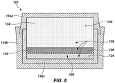
- a cross-sectional view of a mold 122 in a process for forming a polycrystalline table 102 is shown.
- a first plurality of particles 124 comprising a superabrasive material may be disposed in the mold 122.
- a second plurality of particles 126 comprising a superabrasive material may also be disposed in the mold 122 adjacent the first plurality of particles 124.
- a third plurality of particles 128 comprising a mass of hard material may optionally be disposed in the mold 122, the second plurality of particles 126 being interposed between the first plurality of particles 124 and the third plurality of particles 128.
- Particles of the second plurality of particles 126 may have a multi-modal (e.g., bi-modal, tri-modal, etc .) particle size distribution.
- the second plurality of particles 126 may include particles having a first average particle size, and particles having a second average particle size that differs from the first average particle size in an unbonded state.
- the unbonded second plurality of particles 126 may comprise particles having relative and actual sizes as previously described with reference to the second region 108 of the polycrystalline table 102, although it is noted that some degree of grain growth and/or shrinkage may occur during the sintering process used to form the polycrystalline table 102.
- Particles of the first plurality of particles 124 may have a mono-modal particle size distribution in some embodiments. In other embodiments, however, particles of the first plurality of particles 124 may have a multi-modal (e . g ., bi-modal, tri-modal, etc .) particle size distribution. In such embodiments, however, the average grain size of each mode may be about 1 ⁇ m or greater. In other words, particles of the first plurality of particles 124 may be free of nanoparticles of the superabrasive material.
- the unbonded first plurality of particles 124 may comprise particles having relative and actual sizes as previously described with reference to grains of the first region 106 of the polycrystalline table 102, although it is noted that some degree of grain growth and/or shrinkage may occur during the sintering process used to form the polycrystalline table 102, as previously mentioned.
- the first plurality of particles 124 may comprise a first packing density
- the second plurality of particles 126 may comprise a second, greater packing density in the mold 122 when in an unbonded state.
- the second plurality of particles 126 may comprise a multi-modal particle size distribution, enabling the particles 126 to pack more densely.
- the first plurality of particles 124 may comprise, for example, a mono-modal particle size distribution that packs less densely than the second plurality of particles 126.
- a catalyst material 130 which may be used to catalyze formation of inter-granular bonds among particles of the first and second pluralities of particles 124 and 126 a lesser temperature and pressure than might otherwise be required, may also be disposed in the mold 122.
- the catalyst material may comprise catalyst powder dispersed among at least the third plurality of particles 128, and optionally among the first and second pluralities of particles 124 and 126.
- catalyst powder may be provided within the second plurality of particles 126, but not in the first plurality of particles 124, and the catalyst material 130 may be swept into the first plurality of particles 124 from among the second plurality of particles 126.
- catalyst material may sweep among the first plurality of particles 124 before bonding among the particles occurs, and may, therefore, flow among the particles at a rate sufficient to ensure adequate sintering of the first plurality of particles.
- the catalyst material 130 may comprise a catalyst foil or disc interposed between the third plurality of particles 128 and the second plurality of particles 126 or between the second plurality of particles 126 and the first plurality of particles 124. Further, the catalyst material 130 may be coated on at least some particles of the second plurality of particles 126. For example, at least some particles of the second plurality of particles 126 may be coated with the catalyst material 130 using a chemical solution deposition process, commonly known in the art as a sol-gel coating process. The third plurality of particles 128 may be fully sintered to form a substrate 104 having a final density before being placed in the mold 122.
- the second plurality of particles 126 may be pressed with catalyst material 130 (e.g., in the form of a catalyst powder) to form a green second region 136 of a polycrystalline table 102.
- catalyst material 130 e.g., in the form of a catalyst powder
- a non-planar interface design such as, for example, the non-planar interface designs discussed previously in connection with FIGS. 5 through 7F , may be imparted to the green substrate 132, the green second region 136, or both.
- catalyst material 130 in the form of catalyst powder that is dispersed among either the first plurality of particles 124 or the second plurality of particles 126 may have an average particle size of between about 10 nm and about 1 ⁇ m. Further, it may be desirable to select the average particle size of the catalyst powder such that a ratio of the average particle size of the catalyst powder to the average particle size of the particles with which the catalyst powder is mixed is within the range of from about 1:10 to about 1:1000, or even within the range from about 1:100 to about 1:1000, as disclosed in U.S. Patent Application Publication No. 2010/0186304 A1, which published July 29, 2010 , in the name of Burgess et al.
- Particles of catalyst material 130 may be mixed with the first, second, or third pluralities of particles 124, 126, and 128 using techniques known in the art, such as standard milling techniques, by forming and mixing a slurry that includes the particles of catalyst material 130 and the first, second, or third pluralities of particles 124, 126, and 128 in a liquid solvent, and subsequently drying the slurry, etc.
- An optional fourth plurality of particles 129 may also be disposed in the mold 122.
- the fourth plurality of particles 129 may be dispersed among the first plurality of particles 124.
- the fourth plurality of particles 129 may comprise a non-catalyst material that is removable using a leaching agent, such as, for example, gallium, indium, or tungsten. Admixture of the fourth plurality of particles 129 among the first plurality of particles 124 may enable the second plurality of particles 126 to have a greater packing density than the first plurality of particles 124.
- the mold 122 may include one or more generally cup-shaped members, such as the cup-shaped member 134a, the cup-shaped member 134b, and the cup-shaped member 134c, which may be assembled and swaged and/or welded together to form the mold 122.
- the first, second, and third pluralities of particles 124, 126, and 128 and the catalyst material 130 may be disposed within the inner cup-shaped member 134c, as shown in FIG. 8 , which has a circular end wall and a generally cylindrical lateral side wall extending perpendicularly from the circular end wall, such that the inner cup-shaped member 134c is generally cylindrical and includes a first closed end and a second, opposite open end.
- the assembly optionally may be subjected to a cold pressing process to compact the first plurality of particles 124, the second plurality of particles 126, and the optional third and fourth pluralities of particles 128 and 129 in the mold 122.
- the optional third plurality of particles 128 comprising a hard material is present in the form of a fully sintered substrate, the first, second, and optional fourth pluralities of particles 124, 126, and 129 may simply be compacted against the third plurality of particles 128.
- the resulting assembly then may be sintered in an HTHP process in accordance with procedures known in the art to form a cutting element 100 having polycrystalline table 102 comprising a superabrasive polycrystalline material including a first region 106 and a second region 108, generally as previously described with reference to FIGS. 1 through 6 .
- the first plurality of particles 124 FIG. 7
- the second plurality of particles 126 FIG. 7
- the pressures in the heated press may be greater than about 5.0 GPa and the temperatures may be greater than about 1,400°C. In some embodiments, the pressures in the heated press may be greater than about 6.5 GPa ( e.g ., about 6.7 GPa). Furthermore, the materials being sintered may be held at such temperatures and pressures for a time period between about 30 seconds and about 20 minutes.
- FIG. 9 a cross-sectional view of a mold 122 in another process for forming a polycrystalline table 102 is shown.
- a separately formed polycrystalline table 102a having a first permeability.
- Another polycrystalline table 102b having a second, lesser permeability attached on an end of a substrate 104 is also disposed in the mold.
- the separately formed polycrystalline table 102a, the other polycrystalline table 102b, and the substrate 104 may be subjected to a sintering process, such as, for example, an HTHP process as has been described previously, in the mold 122.
- the separately formed polycrystalline table 102a and the other polycrystalline table 102b may be sintered in the presence of catalyst material 130.
- catalyst material 130 may remain in interstitial spaces between interbonded grains of superabrasive material after the original sintering process used to form the separately formed and the other polycrystalline tables 102a and 102b.
- the separately formed polycrystalline table 102a may be at least partially leached to remove at least some catalyst material 130 therefrom prior to disposing it in the mold 122 adjacent the other polycrystalline table 102b.
- catalyst material 130 may be provided in the form of a disc or foil interposed between the separately formed and the other polycrystalline tables 102a and 102b.
- the separately formed polycrystalline table 102a may have a first permeability and may be used to form a first region 106 having a first permeability within a resulting polycrystalline table 102.
- the other polycrystalline table 102b may have a second, lower permeability and may be used to form a second region 108 having a second, lower permeability within the resulting polycrystalline table 102.
- a cross-sectional view of a mold 122 in another process for forming a polycrystalline table 102 is shown.
- the separately formed polycrystalline table 102a may comprise a first region 106 having a first permeability and a second region 108 having a second, lower permeability.
- the separately formed polycrystalline table 102a may be disposed on another polycrystalline table 102b with the second region 108 interposed between the first region 106 and the other polycrystalline table 102b.
- the separately formed polycrystalline table 102a may be at least substantially fully leached prior to being disposed in the mold 122.
- the second region 108 may impede flow of the catalyst material 130 from the substrate 104 and the other polycrystalline table 102b into the separately formed polycrystalline table 102a.
- the first region 106 may remain at least substantially fully free of catalyst material 130 without requiring subsequent leaching or requiring less subsequent leaching.
- the resulting polycrystalline table 102 may particularly resemble that shown in FIG. 4 .
- the separately formed polycrystalline table 102a may not be at least substantially fully leached, and catalyst material 130 may remain in the first and second regions 106 and 108 within the separately formed polycrystalline table 102a.
- a polycrystalline table 102 comprising a first region 106 having a first permeability and at least a second region 108 having a second, lesser permeability may be attached on an end of a substrate 104.
- the polycrystalline table 102 may then be subjected to a leaching process to substantially fully remove catalyst material 130 from at least the first region 106 therein.
- a cutting element 100 as shown in any of FIGS. 1 through 7F , may be formed.
- the second region 108 may comprise a multi-modal grain size distribution, there being larger grains 138 of superabrasive material and smaller grains 140 of superabrasive material.
- the smaller grains 140 may comprise nano-sized grains.
- the larger grains 138 and the smaller grains 140 may be interbonded to form a polycrystalline material.
- Catalyst material 130 may be disposed in the interstitial spaces among interbonded grains 138 and 140 of superabrasive material.
- the second region 108 may comprise a volume percentage of catalyst material 130 disposed in interstitial spaces among interbonded grains 138 and 140 of superabrasive material.
- the first region 106 may comprise a mono-modal grain size distribution, there being grains 142 having a size clustered about a single average grain size.
- the first region 106 may be devoid of nano-sized grains.
- the grains 142 may be interbonded to form a polycrystalline material.
- Catalyst material 130 may be disposed in the interstitial spaced among interbonded grains 142 of superabrasive material.
- the first region 106 may comprise a volume percentage of catalyst material 130 disposed in interstitial spaces among interbonded grains 142 of superabrasive material. Comparing the microstructure shown in FIG. 11 to that shown in FIG. 12 , the volume percentage of catalyst material 130 disposed in interstitial spaces among interbonded grains 138 and 140 of superabrasive material within the second region 108 may be smaller than the volume percentage of catalyst material 130 disposed in interstitial spaces among interbonded grains 142 of superabrasive material within the first region 106.
- FIG. 13 a simplified cross-sectional view is shown of how the first region 106 shown in FIG. 12 after being subjected to a leaching process.
- aqua regia a mixture of concentrated nitric acid (HNO 3 ) and concentrated hydrochloric acid (HCl)
- HNO 3 concentrated nitric acid
- HCl concentrated hydrochloric acid
- One particularly suitable leaching agent is hydrochloric acid (HCl) at a temperature of above 110°C, which may be provided in contact with exposed surfaces of the first region 106 of the polycrystalline table 102 for a period of about 2 hours to about 60 hours, depending upon the size of the polycrystalline table 102.
- Surfaces of the cutting element 100 as shown in any of FIGS. 1 through 6 , other than those to be leached, such as surfaces of the substrate 104, and/or exposed lateral surfaces of the second region 108 of the polycrystalline table 102, may be covered ( e.g., coated) with a protective material, such as a polymer material, that is resistant to etching or other damage from the leaching agent.
- the surfaces to be leached then may be exposed to and brought into contact with the leaching fluid by, for example, dipping or immersing at least a portion of the first region 106 of the polycrystalline table 102 of the cutting element 100 into the leaching fluid.
- the leaching agent will penetrate into the first region 106 of the polycrystalline compact 102 of the cutting element 100 from the exposed surfaces thereof.
- the depth or distances into the first region 106 of the polycrystalline table 102 from the exposed surfaces reached by the leaching fluid will be a function of the time to which the first region 106 is exposed to the leaching fluid (i.e., the leaching time) and the rate at which the leaching agent penetrates through the microstructure of the first region 106.
- the rate of flow of the leaching fluid through the second region 108 of the polycrystalline table 102 during the leaching process may be relatively lower than the flow rate through the first region 106 due to the reduced permeability of the second region 108.
- the interface 112 between the first and second regions 106 and 108 may serve as a barrier to hinder or impede the flow of leaching fluid further into the polycrystalline table 102, and specifically, into the second region 108 of the polycrystalline table 102.
- the rate at which the leaching depth increases as a function of time may be reduced to a significant extent.
- a specific desirable depth at which it is desired to leach catalyst material 130 from the polycrystalline table 102 may be selected and defined by positioning the interface 112 between the first region 106 and the second region 108 at a desirable, selected depth or location within the polycrystalline table 102.
- the interface 112 may be used to hinder or impede the flow of leaching fluid, and, hence, leaching of catalyst material 130 out from the polycrystalline table 102, beyond a desirable, selected leaching depth, at which the interface 112 is positioned. Stated another way, the flow of the leaching fluid through the second region 108 of the polycrystalline table 102 among the grains 138 and 140 may be impeded using the smaller grains 140 of superabrasive material in the second region 108 of the polycrystalline table 102 as a barrier to the leaching fluid.
- leaching fluid may cause further leaching of catalyst material 130 from the second region 108 of the polycrystalline table 102, although at a slower leaching rate than that at which catalyst material 130 is leached out from the first region 106 of the polycrystalline table 102.
- Leaching catalyst material 130 out from the second region 108 may be undesirable, and the duration of the leaching process may be selected such that catalyst material 130 is not leached from the second region 108 in any significant quantity ( i.e., in any quantity that would measurably alter the strength or fracture toughness of the polycrystalline table 102).
- catalyst material 130 may be leached out from the interstitial spaces within the first region 106 of the polycrystalline table 102 using a leaching fluid without entirely removing catalyst material 130 from the interstitial spaces within the second region 108 of the polycrystalline table 102.
- the catalyst material 130 may remain within at least substantially all (e . g ., within about 98% by volume or more) of the interstitial spaces within the second region 108 of the polycrystalline table 102.
- the catalyst material 130 may be substantially fully removed from the first region 106 of the polycrystalline table 102.
- the interstitial spaces among the interbonded grains 142 within the first region 106 may comprise voids 144 after the leaching process.
- the voids 144 may be filled with environmental fluid (e.g., air) and be substantially completely free of catalyst material 130.
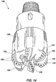
- FIG. 14 a perspective view of an earth-boring drill bit 146 having cutting elements 100, such as any of the cutting elements described previously in connection with FIGS. 1 through 7F , attached thereto, at least one cutting element having a polycrystalline table 102 of the present disclosure.
- the earth-boring drill bit 146 includes a bit body 148 having blades 150 extending from the bit body 148.
- the cutting elements 100 may be secured within pockets 152 formed in the blades 150.
- cutting elements 100 and polycrystalline tables 102 as described herein may be bonded to and used on other types of earth-boring tools, including, for example, roller cone drill bits, percussion bits, core bits, eccentric bits, bicenter bits, reamers, expandable reamers, mills, hybrid bits, and other drilling bits and tools known in the art.
- earth-boring tools including, for example, roller cone drill bits, percussion bits, core bits, eccentric bits, bicenter bits, reamers, expandable reamers, mills, hybrid bits, and other drilling bits and tools known in the art.
Landscapes
- Engineering & Computer Science (AREA)
- Mechanical Engineering (AREA)
- Mining & Mineral Resources (AREA)
- Life Sciences & Earth Sciences (AREA)
- Geology (AREA)
- Manufacturing & Machinery (AREA)
- Crystallography & Structural Chemistry (AREA)
- Physics & Mathematics (AREA)
- Environmental & Geological Engineering (AREA)
- Fluid Mechanics (AREA)
- Chemical & Material Sciences (AREA)
- General Life Sciences & Earth Sciences (AREA)
- Geochemistry & Mineralogy (AREA)
- Polishing Bodies And Polishing Tools (AREA)
- Catalysts (AREA)
Abstract
Description
- This application claims the benefit of the filing date of United States Patent Application Serial Number
13/040,921, filed March 4, 2011 - Embodiments of the present disclosure relate generally to polycrystalline tables, polycrystalline elements, and related methods. Specifically, embodiments of the disclosure relate to polycrystalline elements having polycrystalline tables with a substantially fully leached region and methods of forming such polycrystalline elements.
- Earth-boring tools for forming wellbores in subterranean earth formations may include a plurality of cutting elements secured to a body. For example, fixed-cutter earth-boring rotary drill bits (also referred to as "drag bits") include a plurality of cutting elements that are fixedly attached to a bit body of the drill bit. Similarly, roller cone earth-boring rotary drill bits may include cones that are mounted on bearing pins extending from legs of a bit body such that each cone is capable of rotating about the bearing pin on which it is mounted. A plurality of cutting elements may be mounted to each cone of the drill bit.
- The cutting elements used in such earth-boring tools often include polycrystalline diamond compact (often referred to as "PDC") cutting elements, also termed "cutters," which are cutting elements that include a polycrystalline diamond (PCD) material, which may be characterized as a superabrasive or superhard material. Such polycrystalline diamond materials are formed by sintering and bonding together relatively small synthetic, natural, or a combination of synthetic and natural diamond grains or crystals, termed "grit," under conditions of high temperature and high pressure in the presence of a catalyst, such as, for example, cobalt, iron, nickel, or alloys and mixtures thereof, to form a layer of polycrystalline diamond material, also called a diamond table. These processes are often referred to as high temperature/high pressure ("HTHP") processes. The cutting element substrate may comprise a cermet material, i.e., a ceramic-metal composite material, such as, for example, cobalt-cemented tungsten carbide. In some instances, the polycrystalline diamond table may be formed on the cutting element, for example, during the HTHP sintering process. In such instances, cobalt or other catalyst material in the cutting element substrate may be swept into the diamond grains or crystals during sintering and serve as a catalyst material for forming a diamond table from the diamond grains or crystals. Powdered catalyst material may also be mixed with the diamond grains or crystals prior to sintering the grains or crystals together in an HTHP process. In other methods, however, the diamond table may be formed separately from the cutting element substrate and subsequently attached thereto.
- To reduce problems associated with differences in thermal expansion and chemical breakdown of the diamond crystals in PDC cutting elements, "thermally stable" polycrystalline diamond compacts (which are also known as thermally stable products or "TSPs") have been developed. Such a thermally stable polycrystalline diamond compact may be formed by leaching catalyst material out from interstitial spaces between the interbonded grains in the diamond table. However, a conventional diamond table may require up to five weeks or even longer to leach substantially all the catalyst material from the interstitial spaces between interbonded grains, slowing down production.
- In some embodiments, the disclosure includes polycrystalline elements, comprising a substrate and a polycrystalline table attached to an end of the substrate. The polycrystalline table comprises a first region of superabrasive material having a first permeability and at least a second region of superabrasive material having a second, lesser permeability, the at least second region being interposed between the substrate and the first region.
- In other embodiments, the disclosure includes methods of forming a polycrystalline element, comprising disposing a first plurality of particles comprising a superabrasive material, a second plurality of particles comprising a superabrasive material, a catalyst material, and a third plurality of particles comprising a mass of hard material in a mold. The first and second pluralities of particles are sintered in the presence of the catalyst material and the third plurality of particles is also sintered to form a polycrystalline table having a first region comprising a first permeability and at least a second region comprising a second, lesser permeability attached to a substrate, the at least a second region being interposed between the first region and the substrate. Catalyst material is removed from at least the first region of the polycrystalline table.
- In additional embodiments, the disclosure includes methods of forming a polycrystalline element comprising attaching a polycrystalline table comprising a first region of superabrasive material having a first permeability and at least a second region of superabrasive material having a second, lesser permeability to an end of a substrate, the at least a second region being interposed between the first region and the substrate. Catalyst material is removed from at least the first region of the polycrystalline table.
- In still further embodiments, the disclosure includes methods of forming a polycrystalline element, comprising forming a first polycrystalline table having a first permeability. The first polycrystalline table is bonded to another polycrystalline table having another, lesser permeability attached to a substrate. Catalyst material is leached from at least the first polycrystalline table.
- In other embodiments, the disclosure includes methods of forming a polycrystalline element comprising forming a first polycrystalline table of superabrasive material in the presence of a catalyst material, the first polycrystalline table having a first region having a first permeability and a second region having a second, lower permeability. The catalyst material is at least substantially fully leached from at least the first region of the first polycrystalline table. The first polycrystalline table is bonded to another polycrystalline table of superabrasive material attached to an end of a substrate of hard material, the second region being interposed between the first region and the other polycrystalline table.
- A polycrystalline element is provided, comprising: a substrate; and a polycrystalline table attached to an end of the substrate and comprising a first region of superabrasive material having a first permeability and at least a second region of superabrasive material having a second, lesser permeability, the at least second region being interposed between the substrate and the first region.
- Preferably, the first region is at least substantially fully leached of catalyst material.
- Preferably, an interface between the first and at least a second regions of the polycrystalline table comprises a non planar interface.
- Preferably, the polycrystalline table further comprises a third region disposed adjacent the at least a second region on an end opposing the first region.
- Preferably, the first region comprises a first volume percentage of superabrasive material and the at least a second region comprises a second, greater volume percentage of superabrasive material.
- Preferably, the first region comprises a first average grain size of grains of superabrasive material and the at least a second region comprises a second, smaller average grain size of grains of superabrasive material.
- Preferably, the at least a second region comprises at least some nano-sized grains.
- Preferably, the first region comprises a first volume percentage of interstitial spaces among interbonded grains of superabrasive material and the at least a second region comprises a second, smaller volume percentage of interstitial spaces among interbonded grains of superabrasive material.
- Preferably, the first region comprises interstitial spaces having a first interconnectivity and the at least a second region comprises interstitial spaces having a second, lesser interconnectivity.
- A method of forming a polycrystalline element is provided, comprising: disposing a first plurality of particles comprising a superabrasive material, a second plurality of particles comprising a superabrasive material, a catalyst material, and a third plurality of particles comprising a mass of hard material in a mold; sintering the first and second pluralities of particles in the presence of the catalyst material and the third plurality of particles to form a polycrystalline table having a first region comprising a first permeability and at least a second region comprising a second, lesser permeability attached to a substrate, the at least a second region being interposed between the first region and the substrate; and removing catalyst material from at least the first region of the polycrystalline table.
- Preferably, the method further comprises pressing the second plurality of particles to form a green part prior to disposing the second plurality of particles in the mold.
- Preferably, pressing the second plurality of particles to form a green part prior to disposing the second plurality of particles in the mold comprises imparting a non-planar interface design to the green part.
- Preferably, the method further comprises disposing a fourth plurality of particles comprising a non-catalyst material removable by a leaching agent dispersed among the first plurality of particles in the mold.
- Preferably, disposing a first plurality of particles comprising a superabrasive material, a second plurality of particles comprising the superabrasive material, a catalyst material, and a third plurality of particles comprising a mass of hard material in a mold comprises disposing the first plurality of particles having a first packing density and the second plurality of particles having a second, greater packing density in the mold.
- Preferably, disposing a first plurality of particles comprising a superabrasive material, a second plurality of particles comprising the superabrasive material, a catalyst material, and a third plurality of particles comprising a mass of hard material in a mold comprises disposing the first plurality of particles having a first average particle size and the a second plurality of particles having a second, smaller average particle size in the mold.
- Preferably, disposing the first plurality of particles having a first average particle size and the second plurality of particles having a second, smaller average particle size in the mold comprises disposing the second plurality of particles comprising at least some nanoparticles in the mold.
- Preferably, the method further comprises coating at least some of the first plurality of particles with the catalyst material using chemical solution deposition prior to disposing the first plurality of particles in the mold.
- Preferably, sintering the first and second pluralities of particles in the presence of the catalyst material and the third plurality of particles to form a polycrystalline table having a first region comprising a first permeability and at least a second region comprising a second, lesser permeability attached to a substrate comprises sintering the first and at least a second pluralities of particles in the presence of the catalyst material and the third plurality of particles to form a polycrystalline table having a first region comprising a first volume percentage of catalyst material disposed in interstitial spaces among interbonded grains of superabrasive material and at least a second region comprising a second, smaller volume percentage of catalyst material disposed in interstitial spaces among interbonded grains of superabrasive material.
- A method of forming a polycrystalline element is provided, comprising: attaching a polycrystalline table comprising a first region of superabrasive material having a first permeability and at least a second region of superabrasive material having a second, lesser permeability to an end of a substrate, the at least a second region being interposed between the first region and the substrate; and removing catalyst material from at least the first region of the polycrystalline table.
- A method of forming a polycrystalline element is provided, comprising: forming a first polycrystalline table having a first permeability; bonding the first polycrystalline table to another polycrystalline table having another, lesser permeability attached to a substrate; and leaching catalyst material from at least the first polycrystalline table.
- While the specification concludes with claims particularly pointing out and distinctly claiming that which is regarded as the present invention, various features and advantages of embodiments of this invention may be more readily ascertained from the following description of embodiments of the invention when read in conjunction with the accompanying drawings, in which:
-
FIG. 1 is a partial cutaway perspective view of a cutting element having a polycrystalline table of the present disclosure; -
FIG. 2 illustrates a cross-sectional side view of another cutting element having a dome-shaped polycrystalline table of the present disclosure; -
FIG. 3 is a cross-sectional side view of a further cutting element having another polycrystalline table configuration of the present disclosure; -
FIG. 4 depicts a cross-sectional side view of a cutting element having a further polycrystalline table configuration of the present disclosure; -
FIG. 5 illustrates a cross-sectional side view of a cutting element having a polycrystalline table of the present disclosure with a non-planar interface design at an interface between the polycrystalline table and a substrate; -
FIG. 6 illustrates a cross-sectional side view of a cutting element having a polycrystalline table of the present disclosure with a non-planar interface design at an interface between regions of the polycrystalline table; -
FIGS. 7A through 7F are cross-sectional top views of interface designs for polycrystalline tables of the present disclosure; -
FIG. 8 depicts a cross-sectional view of a mold in a process for forming a polycrystalline table of the present disclosure; -
FIG. 9 illustrates a cross-sectional view of a mold in another process for forming a polycrystalline table of the present disclosure; -
FIG. 10 shows a cross-sectional view of a mold in another process for forming a polycrystalline table of the present disclosure; -
FIG. 11 is a simplified cross-sectional view of a region of a polycrystalline table of the present disclosure; -
FIG. 12 illustrates a simplified cross-sectional view of another region of a polycrystalline table of the present disclosure; -
FIG. 13 is a simplified cross-sectional view of the region shown inFIG. 10 after a leaching process; and -
FIG. 14 is a perspective view of an earth-boring drill bit having cutting elements attached thereto, at least one cutting element having a polycrystalline table of the present disclosure. - The illustrations presented herein are not meant to be actual views of any particular earth-boring tool, cutting element, or bearing, but are merely idealized representations that are employed to describe the embodiments of the disclosure. Additionally, elements common between figures may retain the same or similar numerical designation.
- The terms "earth-boring tool" and "earth-boring drill bit," as used herein, mean and include any type of bit or tool used for drilling during the formation or enlargement of a wellbore in a subterranean formation and include, for example, fixed-cutter bits, roller cone bits, percussion bits, core bits, eccentric bits, bicenter bits, reamers, mills, drag bits, hybrid bits, and other drilling bits and tools known in the art.
- As used herein, the term "superabrasive material" means and includes any material having a Knoop hardness value of about 3,000 Kgf/mm2 (29,420 MPa) or more. Superabrasive materials include, for example, diamond and cubic boron nitride. Superabrasive materials may also be characterized as "superhard" materials.
- As used herein, the term "polycrystalline table" means and includes any structure comprising a plurality of grains (i.e., crystals) of material that are bonded directly together by inter-granular bonds. The crystal structures of the individual grains of the material may be randomly oriented in space within the polycrystalline material.
- As used herein, the terms "inter-granular bond" and "interbonded" mean and include any direct atomic bond (e.g., covalent, metallic, etc.) between atoms in adjacent grains of superabrasive material.
- As used herein, the terms "nanoparticle" and "nano-sized" mean and include any particle, such as, for example, a crystal or grain, having an average particle diameter of between about 1 nm and 500 nm.
- The term "green" as used herein means unsintered.
- The term "green part" as used herein means an unsintered structure comprising a plurality of discrete particles, which may be held together by a binder material, the unsintered structure having a size and shape allowing the formation of a part or component suitable for use in earth-boring applications from the structure by subsequent manufacturing processes including, but not limited to, machining and densification.
- The term "sintering" as used herein means temperature driven mass transport, which may include densification and/or coarsening of a particulate component, and typically involves removal of at least a portion of the pores between the starting particles (accompanied by shrinkage) combined with coalescence and bonding between adjacent particles.
- As used herein, the term "material composition" means the chemical composition and microstructure of a material. In other words, materials having the same chemical composition but a different microstructure are considered to having different material compositions.
- As used herein, the term "tungsten carbide" means any material composition that contains chemical compounds of tungsten and carbon, such as, for example, WC, W2C, and combinations of WC and W2C. Tungsten carbide includes, for example, cast tungsten carbide, sintered tungsten carbide, and macrocrystalline tungsten carbide.
- Referring to
FIG. 1 , a partial cutaway perspective view of acutting element 100 is shown. The cuttingelement 100 includes a polycrystalline table 102 attached on an end of asubstrate 104. The polycrystalline table 102 may comprise a disc attached on an end of thecylindrical substrate 104 at aplanar substrate interface 116. The polycrystalline table 102 includes afirst region 106 and at least asecond region 108. Thefirst region 106 may comprise a layer including a cuttingface 110 of the polycrystalline table 102 and extending toward thesubstrate 104. Thesecond region 108 may be interposed between thefirst region 106 and thesubstrate 104. Aninterface 112 may lie at the boundary between thefirst region 106 and thesecond region 108.Chamfers 114 may be formed at the peripheral edges of the polycrystalline table 102, thesubstrate 104, or both. - The polycrystalline table 102 may comprise a polycrystalline superabrasive material. For example, the polycrystalline table 102 may comprise natural diamond, synthetic diamond, a combination of natural and synthetic diamond, cubic boron nitride, carbon nitrides, and other superabrasive materials known in the art. Individual grains of the superabrasive material may be interbonded, such as, for example, by diamond-to-diamond bonding, to form a three-dimensional polycrystalline structure. A catalyst material for catalyzing formation of the inter-granular bonds of the polycrystalline material may comprise, for example, Group VIIIB metals such as cobalt, iron, nickel, or alloys and mixtures thereof.
- The
substrate 104 may comprise a hard material. For example, the hard material may comprise a ceramic-metal composite material (i.e., a "cermet" material) comprising a plurality of hard ceramic particles dispersed throughout a metal matrix material. The hard ceramic particles may comprise carbides, nitrides, oxides, and borides (including boron carbide (B4C)). More specifically, the hard ceramic particles may comprise carbides and borides made from elements such as W, Ti, Mo, Nb, V, Hf, Ta, Cr, Zr, Al, and Si. By way of example and not limitation, materials that may be used to form hard ceramic particles include tungsten carbide, titanium carbide (TiC), tantalum carbide (TaC), titanium diboride (TiB2), chromium carbides, titanium nitride (TiN), aluminum oxide (Al2O3), aluminum nitride (AlN), and silicon carbide (SiC). The metal matrix material of the ceramic-metal composite material may include, for example, cobalt-based, iron-based, nickel-based, iron- and nickel-based, cobalt- and nickel-based, and iron- and cobalt-based alloys. The matrix material may also be selected from commercially pure elements such as cobalt, iron, and nickel. For example, the hard material may comprise a plurality of tungsten carbide particles in a cobalt matrix, known in the art as cobalt-cemented tungsten carbide. - Referring to
FIG. 2 , a cross-sectional side view of another cutting element 100' is shown. The cutting element 100' includes a polycrystalline table 102 attached on an end of asubstrate 104. The polycrystalline table 102 may comprise a hollow dome shape, thesubstrate 104 including a dome-shaped protrusion forming a dome-shapedinterface 116 to which the polycrystalline table 102 is attached. In other embodiments, the polycrystalline table 102 may comprise a solid dome shape, such as, for example, a hemisphere, attached to the polycrystalline table 102 at aplanar substrate interface 116. In still other embodiments, the polycrystalline table 102 may comprise other shapes, such as, for example, chisel-shaped, tombstone-shaped, or other shapes and configurations for the cuttingface 110 as known in the art. The polycrystalline table 102 includes afirst region 106 and at least asecond region 108. Thefirst region 106 may comprise a dome-shaped layer including a cuttingface 110 of the polycrystalline table 102 and extending toward thesubstrate 104. Thesecond region 108 may be interposed between thefirst region 106 and thesubstrate 104. Thesubstrate 104 may include anintermediate layer 118. Theintermediate layer 118 may comprise a combination of the superabrasive material of the polycrystalline table 102 and the hard material of the remainder of thesubstrate 104. Concentrations of the superabrasive material and the hard material may comprise a gradient of varying percentages of the superabrasive material and the hard material through a depth of theintermediate layer 118 to provide a transition between the polycrystalline table 102 and thesubstrate 104. Thus, theintermediate layer 118 may enable a stronger attachment between the polycrystalline table and the substrate. - Referring to
FIG. 3 , a cross-sectional side view of another cuttingelement 100 is shown. The cuttingelement 100 includes a polycrystalline table 102 attached on an end of asubstrate 104. The polycrystalline table 102 may comprise afirst region 106 and at least asecond region 108. Thefirst region 106 may extend from a cuttingface 110 of the polycrystalline table 102 toward thesubstrate 104 and having an annular extension extending toward thesubstrate 104 at the periphery of the polycrystalline table 102. The annular extension may abut thesubstrate 104 at a portion of thesubstrate interface 116. Thus, thesecond region 108 may not extend to the periphery of the polycrystalline table 102, the annular extension of thefirst region 106 surrounding thesecond region 108 at the radially outer portion thereof. Thesecond region 108 may be interposed between thefirst region 106 and thesubstrate 104. - Referring to
FIG. 4 , a cross-sectional side view of another cuttingelement 100 is shown. The cuttingelement 100 includes a polycrystalline table 102 attached on an end of asubstrate 104. The polycrystalline table 102 may comprise afirst region 106, asecond region 108, and athird region 120. Thefirst region 106 may extend from a cuttingface 110 of the polycrystalline table 102 toward the substrate to aninterface 112 with thesecond region 108. Thesecond region 108 may be interposed between thefirst region 106 and thethird region 120. Thethird region 120 may extend from thesecond region 108 to thesubstrate interface 116 where the polycrystalline table 102 is attached to thesubstrate 104. Thus, thethird region 120 may be disposed adjacent thesecond region 108 on an end opposing thefirst region 106. - Referring to
FIG. 5 , a cross-sectional side view of another cuttingelement 100 is shown. The cuttingelement 100 includes a polycrystalline table 102 attached on an end of asubstrate 104. The polycrystalline table 102 includes afirst region 106 and at least asecond region 108. Thesecond region 108 may be interposed between thefirst region 106 and thesubstrate 104. Asubstrate interface 116 between the polycrystalline table 102 and thesubstrate 104 may comprise a non-planar interface design. For example, the non-planar interface design may comprise a series of alternating protrusions and recesses, concentric annular rings, radially extending spokes, or other non-planar interface designs known in the art. - Referring to
FIG. 6 , a cross-sectional side view of another cuttingelement 100 is shown. The cuttingelement 100 includes a polycrystalline table 102 attached on an end of asubstrate 104. The polycrystalline table 102 includes afirst region 106 and at least asecond region 108. Thesecond region 108 may be interposed between thefirst region 106 and thesubstrate 104. Aninterface 112 between thefirst region 106 and thesecond region 108 may comprise a non-planar interface design. For example, the non-planar interface design may comprise a series of alternating protrusions and recesses, concentric annular rings, radially extending spokes, or other non-planar interface designs known in the art. In embodiments where both theinterface 112 between thefirst region 106 and thesecond region 108 and thesubstrate interface 116 between the polycrystalline table 102 and thesubstrate 104 comprise non-planar interface designs, the non-planar interface design located at theinterface 112 between thefirst region 106 and thesecond region 108 may be at least substantially the same as the non-planar interface design located at thesubstrate interface 116 between the polycrystalline table 102 and thesubstrate 104. Alternatively, the non-planar interface design located at theinterface 112 between thefirst region 106 and thesecond region 108 may be different from the non-planar interface design located at thesubstrate interface 116 between the polycrystalline table 102 and thesubstrate 104. As a specific, non-limiting example, the non-planar interface design located at theinterface 112 between thefirst region 106 and thesecond region 108 may comprise concentric rings, and the non-planar interface design located at thesubstrate interface 116 between the polycrystalline table 102 and thesubstrate 104 may comprise radially extending spokes. - Referring to
FIGS. 7A through 7F , cross-sectional top views of cuttingelements 100 are shown. The cross-sections shown are taken within the polycrystalline table 102 and depict portions of thefirst region 106 and thesecond region 108. As shown, the polycrystalline table 102 may comprise a non-planar interface design between thefirst region 106 and thesecond region 108. Similar non-planar interface designs may also be disposed at the substrate interface 116 (seeFIG. 5 ) between the polycrystalline table 102 and thesubstrate 104. It is noted, however, that the boundaries between thefirst region 106 and thesecond region 108 may not be as clear as illustrated inFIGS. 5 through 7F because thefirst region 106 and thesecond region 108 may comprise grains of the same superabrasive material in varying sizes and because some shifting, crushing, fracturing, and growth of the grains may occur during formation of the polycrystalline table 102. Thus, the shapes and designs shown are meant as simplified examples for illustrative purposes. - In each of the embodiments shown in
FIGS. 1 through 7F , afirst region 106 of a polycrystalline table 102 may comprise a polycrystalline region of a first permeability. Asecond region 108 in each of the embodiments shown inFIGS. 1 through 7F may comprise a polycrystalline region of a second, lesser permeability. Thefirst region 106 may be at least substantially fully leached of catalyst material. Thus, thefirst region 106 may be at least substantially free of catalyst material that may otherwise remain in interstitial spaces among interbonded grains of superabrasive material after formation of a polycrystalline table 102. When it is said that the interstitial spaces between the interbonded grains of superabrasive material in thefirst region 106 of the polycrystalline table 102 may be at least substantially free of catalyst material, it is meant that catalyst material is removed from the open, interconnected network of spatial regions among the grains within the microstructure of thefirst region 106, although a relatively small amount of catalyst material may remain in closed, isolated spatial regions between the grains, as a leaching agent may not be able to reach volumes of catalyst material within such closed, isolated spatial regions. The differences in permeability between thefirst region 106 and the second region 108 (i.e., thesecond region 108 having a reduced permeability compared to the first region 106) may enable catalyst material to be removed from thefirst region 106 relatively quickly as compared to removing catalyst material from thesecond region 108. - The
second region 108 may have a lesser permeability than thefirst region 106 because thesecond region 108 comprises a volume percentage of superabrasive material that is greater than the volume percentage of superabrasive material of thefirst region 106. For example, the polycrystalline table 102 may be formed having a microstructure as described inU.S. Patent Application No. 13/010,620, filed January 20, 2011 on behalf of Scott et al. As a non-limiting example, thefirst region 106 may comprise less than or equal to 91 % by volume of the superabrasive material, while thesecond region 108 may comprise greater than or equal to 92% by volume of the superabrasive material. As a specific, non-limiting example, thefirst region 106 may comprise about 85% to about 95% by volume of the superabrasive material and thesecond region 108 may, in turn, comprise about 96% to about 99% by volume of the superabrasive material. Thus, thesecond region 108 may comprise a correspondingly smaller volume percentage of interstitial spaces among interbonded grains of superabrasive material as compared to the volume percentage of interstitial spaces among interbonded grains of superabrasive material of thefirst region 106. Where thesecond region 108 comprises a higher volume percentage of superabrasive material, there may be fewer and smaller interconnected spaces among interbonded grains of superabrasive material and, therefore, fewer and more constricted paths for a leaching agent to penetrate. - The
second region 108 may have a lesser permeability than thefirst region 106 because thesecond region 108 may comprise a smaller average grain size of grains of superabrasive material than the average grain size of grains of superabrasive material of thefirst region 106. For example, grains of thesecond region 108 may comprise an average grain size that is 50 to 150 times smaller than the average grain size of grains of thefirst region 106. As a further example, thefirst region 106 may comprise grains having an average grain size of at least 5 µm, and thesecond region 108 may comprise grains having an average grain size of less than 1 µm. As specific, non-limiting examples, thefirst region 106 may comprise grains having an average grain size of between about 3 µm and about 40 µm, and thesecond region 108 may comprise a mixture of grains, at least some of which have average grain sizes of 500 nm, 200 nm, 150 nm, and even as small as 6 nm. Larger grains may be interspersed among the nano-sized grains (i.e., grains having an average particle diameter of between 1 nm and 500 nm). Where thesecond region 108 comprises a smaller average grain size of grains of superabrasive material, there may be fewer and smaller interconnected spaces among the interbonded grains and, therefore, fewer and more constricted paths for a leaching agent to penetrate. In some embodiments, at least some of the grains of superabrasive material of thesecond region 108 may comprise nano-sized grains (i.e., grains having a diameter less than about 500nm). In addition, the use of a multi-modal size distribution of grains in thesecond region 108 may result in fewer and smaller interconnected spaces among the interbonded grains of superabrasive material. - Further, the
second region 108 may have a lesser permeability than thefirst region 106 because thesecond region 108 may comprise interstitial spaces having a lesser interconnectivity as compared to the interconnectivity of the interstitial spaces of thefirst region 108. For example, the mean free path within the interstitial spaces between the interbonded grains in thefirst region 106 may be about 10% or greater, about 25% or greater, or even about 50% or greater than the mean free path within the interstitial spaces between the interbonded grains in thesecond region 108. Theoretically, the mean free path within the interstitial spaces between the interbonded grains in thefirst region 106 and the mean free path within the interstitial spaces between the interbonded grains in thesecond region 108 may be determined using techniques known in the art, such as those set forth in Ervin E. Underwood, Quantitative Stereology, (Addison-Wesley Publishing Company, Inc. 1970). - Referring to
FIG. 8 , a cross-sectional view of amold 122 in a process for forming a polycrystalline table 102 is shown. A first plurality ofparticles 124 comprising a superabrasive material may be disposed in themold 122. A second plurality ofparticles 126 comprising a superabrasive material may also be disposed in themold 122 adjacent the first plurality ofparticles 124. A third plurality ofparticles 128 comprising a mass of hard material may optionally be disposed in themold 122, the second plurality ofparticles 126 being interposed between the first plurality ofparticles 124 and the third plurality ofparticles 128. - Particles of the second plurality of
particles 126 may have a multi-modal (e.g., bi-modal, tri-modal, etc.) particle size distribution. For example, the second plurality ofparticles 126 may include particles having a first average particle size, and particles having a second average particle size that differs from the first average particle size in an unbonded state. The unbonded second plurality ofparticles 126 may comprise particles having relative and actual sizes as previously described with reference to thesecond region 108 of the polycrystalline table 102, although it is noted that some degree of grain growth and/or shrinkage may occur during the sintering process used to form the polycrystalline table 102. - Particles of the first plurality of
particles 124 may have a mono-modal particle size distribution in some embodiments. In other embodiments, however, particles of the first plurality ofparticles 124 may have a multi-modal (e.g., bi-modal, tri-modal, etc.) particle size distribution. In such embodiments, however, the average grain size of each mode may be about 1 µm or greater. In other words, particles of the first plurality ofparticles 124 may be free of nanoparticles of the superabrasive material. The unbonded first plurality ofparticles 124 may comprise particles having relative and actual sizes as previously described with reference to grains of thefirst region 106 of the polycrystalline table 102, although it is noted that some degree of grain growth and/or shrinkage may occur during the sintering process used to form the polycrystalline table 102, as previously mentioned. - The first plurality of
particles 124 may comprise a first packing density, and the second plurality ofparticles 126 may comprise a second, greater packing density in themold 122 when in an unbonded state. For example, the second plurality ofparticles 126 may comprise a multi-modal particle size distribution, enabling theparticles 126 to pack more densely. By contrast, the first plurality ofparticles 124 may comprise, for example, a mono-modal particle size distribution that packs less densely than the second plurality ofparticles 126. - A
catalyst material 130, which may be used to catalyze formation of inter-granular bonds among particles of the first and second pluralities ofparticles 124 and 126 a lesser temperature and pressure than might otherwise be required, may also be disposed in themold 122. The catalyst material may comprise catalyst powder dispersed among at least the third plurality ofparticles 128, and optionally among the first and second pluralities ofparticles particles 126, but not in the first plurality ofparticles 124, and thecatalyst material 130 may be swept into the first plurality ofparticles 124 from among the second plurality ofparticles 126. It may be desirable to disperse catalyst powder among the first plurality ofparticles 124, as the rate of flow ofmolten catalyst material 130 through the second plurality ofparticles 126 during the sintering process may be relatively slow due to the reduced permeability of the polycrystalline material formed therefrom, and the relatively small and dispersed interstitial spaces among the particles of the second plurality ofparticles 126 through which thecatalyst material 130 may flow. However, catalyst material may sweep among the first plurality ofparticles 124 before bonding among the particles occurs, and may, therefore, flow among the particles at a rate sufficient to ensure adequate sintering of the first plurality of particles. Thecatalyst material 130 may comprise a catalyst foil or disc interposed between the third plurality ofparticles 128 and the second plurality ofparticles 126 or between the second plurality ofparticles 126 and the first plurality ofparticles 124. Further, thecatalyst material 130 may be coated on at least some particles of the second plurality ofparticles 126. For example, at least some particles of the second plurality ofparticles 126 may be coated with thecatalyst material 130 using a chemical solution deposition process, commonly known in the art as a sol-gel coating process. The third plurality ofparticles 128 may be fully sintered to form asubstrate 104 having a final density before being placed in themold 122. The second plurality ofparticles 126 may be pressed with catalyst material 130 (e.g., in the form of a catalyst powder) to form a greensecond region 136 of a polycrystalline table 102. During this pressing, a non-planar interface design, such as, for example, the non-planar interface designs discussed previously in connection withFIGS. 5 through 7F , may be imparted to thegreen substrate 132, the greensecond region 136, or both. - In some embodiments,
catalyst material 130 in the form of catalyst powder that is dispersed among either the first plurality ofparticles 124 or the second plurality ofparticles 126 may have an average particle size of between about 10 nm and about 1 µm. Further, it may be desirable to select the average particle size of the catalyst powder such that a ratio of the average particle size of the catalyst powder to the average particle size of the particles with which the catalyst powder is mixed is within the range of from about 1:10 to about 1:1000, or even within the range from about 1:100 to about 1:1000, as disclosed inU.S. Patent Application Publication No. 2010/0186304 A1, which published July 29, 2010 , in the name of Burgess et al. Particles ofcatalyst material 130 may be mixed with the first, second, or third pluralities ofparticles catalyst material 130 and the first, second, or third pluralities ofparticles - An optional fourth plurality of
particles 129 may also be disposed in themold 122. The fourth plurality ofparticles 129 may be dispersed among the first plurality ofparticles 124. The fourth plurality ofparticles 129 may comprise a non-catalyst material that is removable using a leaching agent, such as, for example, gallium, indium, or tungsten. Admixture of the fourth plurality ofparticles 129 among the first plurality ofparticles 124 may enable the second plurality ofparticles 126 to have a greater packing density than the first plurality ofparticles 124. - The
mold 122 may include one or more generally cup-shaped members, such as the cup-shapedmember 134a, the cup-shapedmember 134b, and the cup-shapedmember 134c, which may be assembled and swaged and/or welded together to form themold 122. The first, second, and third pluralities ofparticles catalyst material 130 may be disposed within the inner cup-shapedmember 134c, as shown inFIG. 8 , which has a circular end wall and a generally cylindrical lateral side wall extending perpendicularly from the circular end wall, such that the inner cup-shapedmember 134c is generally cylindrical and includes a first closed end and a second, opposite open end. - After providing the first plurality of
particles 124, the second plurality ofparticles 126, and the optional third and fourth pluralities ofparticles mold 122, the assembly optionally may be subjected to a cold pressing process to compact the first plurality ofparticles 124, the second plurality ofparticles 126, and the optional third and fourth pluralities ofparticles mold 122. In embodiments where the optional third plurality ofparticles 128 comprising a hard material is present in the form of a fully sintered substrate, the first, second, and optional fourth pluralities ofparticles particles 128. - The resulting assembly then may be sintered in an HTHP process in accordance with procedures known in the art to form a
cutting element 100 having polycrystalline table 102 comprising a superabrasive polycrystalline material including afirst region 106 and asecond region 108, generally as previously described with reference toFIGS. 1 through 6 . Referring toFIGS. 1 and8 together, the first plurality of particles 124 (FIG. 7 ) may form afirst region 106 of the polycrystalline table 102 (FIG. 2 ), and the second plurality of particles 126 (FIG. 7 ) may form asecond region 108 of the polycrystalline table 102 (FIG. 2 ). - Although the exact operating parameters of HTHP processes will vary depending on the particular compositions and quantities of the various materials being sintered, the pressures in the heated press may be greater than about 5.0 GPa and the temperatures may be greater than about 1,400°C. In some embodiments, the pressures in the heated press may be greater than about 6.5 GPa (e.g., about 6.7 GPa). Furthermore, the materials being sintered may be held at such temperatures and pressures for a time period between about 30 seconds and about 20 minutes.
- Referring to
FIG. 9 , a cross-sectional view of amold 122 in another process for forming a polycrystalline table 102 is shown. Disposed in themold 122 is a separately formed polycrystalline table 102a having a first permeability. Another polycrystalline table 102b having a second, lesser permeability attached on an end of asubstrate 104 is also disposed in the mold. The separately formed polycrystalline table 102a, the other polycrystalline table 102b, and thesubstrate 104 may be subjected to a sintering process, such as, for example, an HTHP process as has been described previously, in themold 122. The separately formed polycrystalline table 102a and the other polycrystalline table 102b may be sintered in the presence ofcatalyst material 130. For example,catalyst material 130 may remain in interstitial spaces between interbonded grains of superabrasive material after the original sintering process used to form the separately formed and the other polycrystalline tables 102a and 102b. In some embodiments, however, the separately formed polycrystalline table 102a may be at least partially leached to remove at least somecatalyst material 130 therefrom prior to disposing it in themold 122 adjacent the other polycrystalline table 102b. Alternatively or in addition tocatalyst material 130 already present,catalyst material 130 may be provided in the form of a disc or foil interposed between the separately formed and the other polycrystalline tables 102a and 102b. Thus, the separately formed polycrystalline table 102a may have a first permeability and may be used to form afirst region 106 having a first permeability within a resulting polycrystalline table 102. Likewise, the other polycrystalline table 102b may have a second, lower permeability and may be used to form asecond region 108 having a second, lower permeability within the resulting polycrystalline table 102. - Referring to
FIG. 10 , a cross-sectional view of amold 122 in another process for forming a polycrystalline table 102 is shown. Disposed in themold 122 is a separately formed polycrystalline table 102a. The separately formed polycrystalline table 102a may comprise afirst region 106 having a first permeability and asecond region 108 having a second, lower permeability. The separately formed polycrystalline table 102a may be disposed on another polycrystalline table 102b with thesecond region 108 interposed between thefirst region 106 and the other polycrystalline table 102b. The separately formed polycrystalline table 102a may be at least substantially fully leached prior to being disposed in themold 122. During sintering, thesecond region 108 may impede flow of thecatalyst material 130 from thesubstrate 104 and the other polycrystalline table 102b into the separately formed polycrystalline table 102a. Thus, thefirst region 106 may remain at least substantially fully free ofcatalyst material 130 without requiring subsequent leaching or requiring less subsequent leaching. In such embodiments, the resulting polycrystalline table 102 may particularly resemble that shown inFIG. 4 . In other embodiments, the separately formed polycrystalline table 102a may not be at least substantially fully leached, andcatalyst material 130 may remain in the first andsecond regions - Using the processes described in relation to
FIGS. 8 and9 , a polycrystalline table 102 comprising afirst region 106 having a first permeability and at least asecond region 108 having a second, lesser permeability may be attached on an end of asubstrate 104. The polycrystalline table 102 may then be subjected to a leaching process to substantially fully removecatalyst material 130 from at least thefirst region 106 therein. Thus, a cuttingelement 100, as shown in any ofFIGS. 1 through 7F , may be formed. - Referring to
FIG. 11 , a simplified cross-sectional view is shown of how asecond region 108 of a polycrystalline table 102 formed by the foregoing methods may appear under magnification. Thesecond region 108 may comprise a multi-modal grain size distribution, there beinglarger grains 138 of superabrasive material andsmaller grains 140 of superabrasive material. Thesmaller grains 140 may comprise nano-sized grains. Thelarger grains 138 and thesmaller grains 140 may be interbonded to form a polycrystalline material.Catalyst material 130 may be disposed in the interstitial spaces amonginterbonded grains second region 108 may comprise a volume percentage ofcatalyst material 130 disposed in interstitial spaces amonginterbonded grains - Referring to
FIG. 12 , a simplified cross-sectional view is shown of how afirst region 106 of a polycrystalline table 102 formed by the foregoing methods may appear under magnification prior to being subjected to a leaching process. Thefirst region 106 may comprise a mono-modal grain size distribution, there beinggrains 142 having a size clustered about a single average grain size. Thefirst region 106 may be devoid of nano-sized grains. Thegrains 142 may be interbonded to form a polycrystalline material.Catalyst material 130 may be disposed in the interstitial spaced amonginterbonded grains 142 of superabrasive material. Thus, thefirst region 106 may comprise a volume percentage ofcatalyst material 130 disposed in interstitial spaces amonginterbonded grains 142 of superabrasive material. Comparing the microstructure shown inFIG. 11 to that shown inFIG. 12 , the volume percentage ofcatalyst material 130 disposed in interstitial spaces amonginterbonded grains second region 108 may be smaller than the volume percentage ofcatalyst material 130 disposed in interstitial spaces amonginterbonded grains 142 of superabrasive material within thefirst region 106. - Referring to
FIG. 13 , a simplified cross-sectional view is shown of how thefirst region 106 shown inFIG. 12 after being subjected to a leaching process. Specifically, as known in the art and described more fully inU.S. Patent No. 5,127,923 andU.S. Patent No. 4,224,380 , aqua regia (a mixture of concentrated nitric acid (HNO3) and concentrated hydrochloric acid (HCl)) may be used to at least substantially removecatalyst material 130 from the interstitial spaces among thegrains 142 in thefirst region 106 of the polycrystalline table 102. It is also known to use boiling hydrochloric acid (HCl) and boiling hydrofluoric acid (HF) as leaching agents. One particularly suitable leaching agent is hydrochloric acid (HCl) at a temperature of above 110°C, which may be provided in contact with exposed surfaces of thefirst region 106 of the polycrystalline table 102 for a period of about 2 hours to about 60 hours, depending upon the size of the polycrystalline table 102. Surfaces of the cuttingelement 100, as shown in any ofFIGS. 1 through 6 , other than those to be leached, such as surfaces of thesubstrate 104, and/or exposed lateral surfaces of thesecond region 108 of the polycrystalline table 102, may be covered (e.g., coated) with a protective material, such as a polymer material, that is resistant to etching or other damage from the leaching agent. The surfaces to be leached then may be exposed to and brought into contact with the leaching fluid by, for example, dipping or immersing at least a portion of thefirst region 106 of the polycrystalline table 102 of the cuttingelement 100 into the leaching fluid. - The leaching agent will penetrate into the
first region 106 of thepolycrystalline compact 102 of the cuttingelement 100 from the exposed surfaces thereof. The depth or distances into thefirst region 106 of the polycrystalline table 102 from the exposed surfaces reached by the leaching fluid will be a function of the time to which thefirst region 106 is exposed to the leaching fluid (i.e., the leaching time) and the rate at which the leaching agent penetrates through the microstructure of thefirst region 106. The rate of flow of the leaching fluid through thesecond region 108 of the polycrystalline table 102 during the leaching process may be relatively lower than the flow rate through thefirst region 106 due to the reduced permeability of thesecond region 108. In other words, theinterface 112 between the first andsecond regions second region 108 of the polycrystalline table 102. As a result, once the leaching fluid reaches the interface 112 (FIGS. 1 through 6 ) between thefirst region 106 and thesecond region 108, the rate at which the leaching depth increases as a function of time may be reduced to a significant extent. Thus, a specific desirable depth at which it is desired toleach catalyst material 130 from the polycrystalline table 102 may be selected and defined by positioning theinterface 112 between thefirst region 106 and thesecond region 108 at a desirable, selected depth or location within the polycrystalline table 102. Theinterface 112 may be used to hinder or impede the flow of leaching fluid, and, hence, leaching ofcatalyst material 130 out from the polycrystalline table 102, beyond a desirable, selected leaching depth, at which theinterface 112 is positioned. Stated another way, the flow of the leaching fluid through thesecond region 108 of the polycrystalline table 102 among thegrains smaller grains 140 of superabrasive material in thesecond region 108 of the polycrystalline table 102 as a barrier to the leaching fluid. - Once the leaching fluid reaches the
interface 112, continued exposure to the leaching fluid may cause further leaching ofcatalyst material 130 from thesecond region 108 of the polycrystalline table 102, although at a slower leaching rate than that at whichcatalyst material 130 is leached out from thefirst region 106 of the polycrystalline table 102. Leachingcatalyst material 130 out from thesecond region 108 may be undesirable, and the duration of the leaching process may be selected such thatcatalyst material 130 is not leached from thesecond region 108 in any significant quantity (i.e., in any quantity that would measurably alter the strength or fracture toughness of the polycrystalline table 102). - Thus,
catalyst material 130 may be leached out from the interstitial spaces within thefirst region 106 of the polycrystalline table 102 using a leaching fluid without entirely removingcatalyst material 130 from the interstitial spaces within thesecond region 108 of the polycrystalline table 102. In some embodiments, thecatalyst material 130 may remain within at least substantially all (e.g., within about 98% by volume or more) of the interstitial spaces within thesecond region 108 of the polycrystalline table 102. By contrast, thecatalyst material 130 may be substantially fully removed from thefirst region 106 of the polycrystalline table 102. As shown inFIG. 12 , the interstitial spaces among theinterbonded grains 142 within thefirst region 106 may comprisevoids 144 after the leaching process. Thevoids 144 may be filled with environmental fluid (e.g., air) and be substantially completely free ofcatalyst material 130. - Referring to
FIG. 14 , a perspective view of an earth-boringdrill bit 146 havingcutting elements 100, such as any of the cutting elements described previously in connection withFIGS. 1 through 7F , attached thereto, at least one cutting element having a polycrystalline table 102 of the present disclosure. The earth-boringdrill bit 146 includes abit body 148 havingblades 150 extending from thebit body 148. The cuttingelements 100 may be secured withinpockets 152 formed in theblades 150. However, cuttingelements 100 and polycrystalline tables 102 as described herein may be bonded to and used on other types of earth-boring tools, including, for example, roller cone drill bits, percussion bits, core bits, eccentric bits, bicenter bits, reamers, expandable reamers, mills, hybrid bits, and other drilling bits and tools known in the art. - The foregoing description is directed to particular embodiments for the purpose of illustration and explanation. It will be apparent, however, to one skilled in the art that many additions, deletions, modifications, and changes to the embodiments set forth above are possible without departing from the scope of the embodiments disclosed herein as hereinafter claimed, including legal equivalents. It is intended that the following claims be interpreted to embrace all such modifications and changes.
Claims (14)
- A polycrystalline element, comprising:a substrate (104); anda polycrystalline table (102) attached to an end of the substrate (104) and comprising a first region (106) of superabrasive material having a first permeability and at least a second region (108) of superabrasive material having a second, lesser permeability, the at least second region (108) being interposed between the substrate (104) and the first region (106);wherein said first region (106) comprises a first volume percentage of interstitial spaces among interbonded grains of superabrasive material and said second region (108) comprises a second, smaller volume percentage of interstitial spaces among interbonded grains of superabrasive material, wherein said polycrystalline table (102) further comprises a third region (118) disposed adjacent said second region (108) on an end opposing said first region (106).
- A polycrystalline element as claimed in claim 1, wherein said first region (106) is at least substantially fully leached of catalyst material.
- A polycrystalline element as claimed in claim 1 or 2, wherein an interface between said first region (106) and said second region (108) of the polycrystalline table (102) comprises a non-planar interface.
- A polycrystalline element as claimed in any of claims 1, 2 or 3, wherein said first region (106) comprises a first average grain size of grains of superabrasive material and said second region (108) comprises a second, smaller average grain size of grains of superabrasive material; and
optionally, wherein said second region (108) comprises at least some nano-sized grains. - A polycrystalline element as claimed in any preceding claim, wherein said first region (106) comprises interstitial spaces having a first interconnectivity and said second region (108) comprises interstitial spaces having a second, lesser interconnectivity.
- A method of forming a polycrystalline element, comprising:disposing a first plurality of particles comprising a superabrasive material, a second plurality of particles comprising a superabrasive material, a catalyst material, and a third plurality of particles comprising a mass of hard material in a mold;sintering the first and second pluralities of particles in the presence of the catalyst material and the third plurality of particles to form a polycrystalline table (102) having a first region (106) comprising a first permeability and at least a second region (108) comprising a second, lesser permeability attached to a substrate (104), said second region (108) being interposed between said first region (106) and said substrate (104), wherein said first region (106) comprises a first volume percentage of interstitial spaces among interbonded grains of superabrasive material and said second region (108) comprises a second, smaller volume percentage of interstitial spaces among interbonded grains of superabrasive material; andremoving catalyst material from at least said first region (106) of said polycrystalline table (102).
- A method as claimed in claim 6, further comprising:pressing the second plurality of particles to form a green part prior to disposing the second plurality of particles in the mold; andoptionally, wherein pressing the second plurality of particles to form a green part prior to disposing the second plurality of particles in the mold comprises imparting a non-planar interface design to the green part.
- A method as claimed in claim 6 or 7, further comprising:disposing a fourth plurality of particles comprising a non-catalyst material removable by a leaching agent dispersed among the first plurality of particles in the mold.
- A method as claimed in any of claims 6, 7 or 8, wherein disposing a first plurality of particles comprising a superabrasive material, a second plurality of particles comprising the superabrasive material, a catalyst material, and a third plurality of particles comprising a mass of hard material in a mold comprises disposing the first plurality of particles having a first packing density and the second plurality of particles having a second, greater packing density in the mold.
- A method as claimed in any of claims 6 through 9, wherein disposing a first plurality of particles comprising a superabrasive material, a second plurality of particles comprising the superabrasive material, a catalyst material, and a third plurality of particles comprising a mass of hard material in a mold comprises disposing the first plurality of particles having a first average particle size and the second plurality of particles having a second, smaller average particle size in the mold; and
optionally, wherein disposing the first plurality of particles having a first average particle size and the second plurality of particles having a second, smaller average particle size in the mold comprises disposing the second plurality of particles comprising at least some nanoparticles in the mold. - A method as claimed in any of claims 6 through 10, further comprising coating at least some of the first plurality of particles with the catalyst material using chemical solution deposition prior to disposing the first plurality of particles in the mold.
- A method as claimed in any of claims 6 through 11, wherein sintering the first and second pluralities of particles in the presence of the catalyst material and the third plurality of particles to form a polycrystalline table (102) having a first region (106) comprising a first permeability and at least a second region (108) comprising a second, lesser permeability attached to a substrate (104) comprises sintering the first and at least a second pluralities of particles in the presence of the catalyst material and the third plurality of particles to form a polycrystalline table (102) having a first region (106) comprising a first volume percentage of catalyst material disposed in interstitial spaces among interbonded grains of superabrasive material and a second region (108) comprising a second, smaller volume percentage of catalyst material disposed in interstitial spaces among interbonded grains of superabrasive material.
- A method of forming a polycrystalline element, comprising:attaching a polycrystalline table (102) comprising a first region (106) of superabrasive material having a first permeability and at least a second region (108) of superabrasive material having a second, lesser permeability to an end of a substrate (104), said second region (108) being interposed between said first region (106) and said substrate (104), wherein said first region (106) comprises a first volume percentage of interstitial spaces among interbonded grains of superabrasive material and said second region (108) comprises a second, smaller volume percentage of interstitial spaces among interbonded grains of superabrasive material; andremoving catalyst material from at least said first region (106) of said polycrystalline table (102).
- A method of forming a polycrystalline element, comprising:forming a first polycrystalline table having a first volume percentage of interstitial spaces among interbonded grains of superabrasive material and exhibiting a first permeability;bonding said first polycrystalline table to another polycrystalline table having a second, smaller volume percentage of interstitial spaces among interbonded grains of superabrasive material and another, lesser permeability attached to a substrate; andleaching catalyst material from at least said first polycrystalline table.
Applications Claiming Priority (3)
| Application Number | Priority Date | Filing Date | Title |
|---|---|---|---|
| US13/040,921 US10099347B2 (en) | 2011-03-04 | 2011-03-04 | Polycrystalline tables, polycrystalline elements, and related methods |
| PCT/US2012/027071 WO2012121942A2 (en) | 2011-03-04 | 2012-02-29 | Polycrystalline tables, polycrystalline elements, and related methods |
| EP12754389.0A EP2681398B1 (en) | 2011-03-04 | 2012-02-29 | Polycrystalline tables, polycrystalline elements, and related methods |
Related Parent Applications (2)
| Application Number | Title | Priority Date | Filing Date |
|---|---|---|---|
| EP12754389.0A Division EP2681398B1 (en) | 2011-03-04 | 2012-02-29 | Polycrystalline tables, polycrystalline elements, and related methods |
| EP12754389.0A Division-Into EP2681398B1 (en) | 2011-03-04 | 2012-02-29 | Polycrystalline tables, polycrystalline elements, and related methods |
Publications (2)
| Publication Number | Publication Date |
|---|---|
| EP3293347A1 true EP3293347A1 (en) | 2018-03-14 |
| EP3293347B1 EP3293347B1 (en) | 2022-04-20 |
Family
ID=46752406
Family Applications (2)
| Application Number | Title | Priority Date | Filing Date |
|---|---|---|---|
| EP17190309.9A Active EP3293347B1 (en) | 2011-03-04 | 2012-02-29 | Polycrystalline tables, polycrystalline elements, and related methods |
| EP12754389.0A Active EP2681398B1 (en) | 2011-03-04 | 2012-02-29 | Polycrystalline tables, polycrystalline elements, and related methods |
Family Applications After (1)
| Application Number | Title | Priority Date | Filing Date |
|---|---|---|---|
| EP12754389.0A Active EP2681398B1 (en) | 2011-03-04 | 2012-02-29 | Polycrystalline tables, polycrystalline elements, and related methods |
Country Status (10)
| Country | Link |
|---|---|
| US (1) | US10099347B2 (en) |
| EP (2) | EP3293347B1 (en) |
| CN (1) | CN103477018B (en) |
| BR (1) | BR112013022625A2 (en) |
| CA (1) | CA2828867C (en) |
| MX (1) | MX2013010086A (en) |
| RU (1) | RU2013144426A (en) |
| SG (1) | SG193270A1 (en) |
| WO (1) | WO2012121942A2 (en) |
| ZA (1) | ZA201306587B (en) |
Cited By (1)
| Publication number | Priority date | Publication date | Assignee | Title |
|---|---|---|---|---|
| WO2020097153A3 (en) * | 2018-11-08 | 2020-06-18 | Varel International Ind., Llc | Method for manufacturing a polycrystalline superhard cutter utilizing leaching passages |
Families Citing this family (35)
| Publication number | Priority date | Publication date | Assignee | Title |
|---|---|---|---|---|
| US7036611B2 (en) | 2002-07-30 | 2006-05-02 | Baker Hughes Incorporated | Expandable reamer apparatus for enlarging boreholes while drilling and methods of use |
| US8028771B2 (en) | 2007-02-06 | 2011-10-04 | Smith International, Inc. | Polycrystalline diamond constructions having improved thermal stability |
| US7942219B2 (en) | 2007-03-21 | 2011-05-17 | Smith International, Inc. | Polycrystalline diamond constructions having improved thermal stability |
| US9297211B2 (en) | 2007-12-17 | 2016-03-29 | Smith International, Inc. | Polycrystalline diamond construction with controlled gradient metal content |
| WO2010129813A2 (en) | 2009-05-06 | 2010-11-11 | Smith International, Inc. | Methods of making and attaching tsp material for forming cutting elements, cutting elements having such tsp material and bits incorporating such cutting elements |
| US8783389B2 (en) | 2009-06-18 | 2014-07-22 | Smith International, Inc. | Polycrystalline diamond cutting elements with engineered porosity and method for manufacturing such cutting elements |
| CA2770306A1 (en) | 2009-08-07 | 2011-02-10 | Smith International, Inc. | Functionally graded polycrystalline diamond insert |
| EP2462310A4 (en) | 2009-08-07 | 2014-04-02 | Smith International | Method of forming a thermally stable diamond cutting element |
| SA111320374B1 (en) | 2010-04-14 | 2015-08-10 | بيكر هوغيس انكوبوريتد | Method Of Forming Polycrystalline Diamond From Derivatized Nanodiamond |
| RU2013110778A (en) | 2010-08-13 | 2014-09-20 | Бейкер Хьюз Инкорпорейтед | CUTTING ELEMENTS CONTAINING NANOPARTICLES AT LEAST ONE AREA, DRILLING TOOLS WITH SUCH CUTTING ELEMENTS AND RELATED METHODS |
| US20120225277A1 (en) * | 2011-03-04 | 2012-09-06 | Baker Hughes Incorporated | Methods of forming polycrystalline tables and polycrystalline elements and related structures |
| US8858662B2 (en) | 2011-03-04 | 2014-10-14 | Baker Hughes Incorporated | Methods of forming polycrystalline tables and polycrystalline elements |
| US9493991B2 (en) | 2012-04-02 | 2016-11-15 | Baker Hughes Incorporated | Cutting structures, tools for use in subterranean boreholes including cutting structures and related methods |
| US10160099B2 (en) | 2012-09-07 | 2018-12-25 | Ulterra Drilling Technologies, L.P. | Selectively leached, polycrystalline structures for cutting elements of drill bits |
| US9140072B2 (en) | 2013-02-28 | 2015-09-22 | Baker Hughes Incorporated | Cutting elements including non-planar interfaces, earth-boring tools including such cutting elements, and methods of forming cutting elements |
| US9650836B2 (en) | 2013-03-01 | 2017-05-16 | Baker Hughes Incorporated | Cutting elements leached to different depths located in different regions of an earth-boring tool and related methods |
| GB201305873D0 (en) * | 2013-03-31 | 2013-05-15 | Element Six Abrasives Sa | Superhard constructions & method of making same |
| US9534450B2 (en) | 2013-07-22 | 2017-01-03 | Baker Hughes Incorporated | Thermally stable polycrystalline compacts for reduced spalling, earth-boring tools including such compacts, and related methods |
| US10047567B2 (en) | 2013-07-29 | 2018-08-14 | Baker Hughes Incorporated | Cutting elements, related methods of forming a cutting element, and related earth-boring tools |
| US9498867B2 (en) * | 2013-11-26 | 2016-11-22 | Baker Hughes Incorporated | Polycrystalline compacts, earth-boring tools including such compacts, and methods of fabricating polycrystalline compacts |
| US10046441B2 (en) | 2013-12-30 | 2018-08-14 | Smith International, Inc. | PCD wafer without substrate for high pressure / high temperature sintering |
| US9845642B2 (en) | 2014-03-17 | 2017-12-19 | Baker Hughes Incorporated | Cutting elements having non-planar cutting faces with selectively leached regions, earth-boring tools including such cutting elements, and related methods |
| US9714545B2 (en) | 2014-04-08 | 2017-07-25 | Baker Hughes Incorporated | Cutting elements having a non-uniform annulus leach depth, earth-boring tools including such cutting elements, and related methods |
| US9605488B2 (en) | 2014-04-08 | 2017-03-28 | Baker Hughes Incorporated | Cutting elements including undulating boundaries between catalyst-containing and catalyst-free regions of polycrystalline superabrasive materials and related earth-boring tools and methods |
| US9863189B2 (en) | 2014-07-11 | 2018-01-09 | Baker Hughes Incorporated | Cutting elements comprising partially leached polycrystalline material, tools comprising such cutting elements, and methods of forming wellbores using such cutting elements |
| JP6701742B2 (en) * | 2015-01-14 | 2020-05-27 | 三菱マテリアル株式会社 | Drilling tip and drilling bit |
| US10633928B2 (en) | 2015-07-31 | 2020-04-28 | Baker Hughes, A Ge Company, Llc | Polycrystalline diamond compacts having leach depths selected to control physical properties and methods of forming such compacts |
| US10605008B2 (en) | 2016-03-18 | 2020-03-31 | Baker Hughes, A Ge Company, Llc | Methods of forming a cutting element including a multi-layered cutting table, and related cutting elements and earth-boring tools |
| CN106392084A (en) * | 2016-09-26 | 2017-02-15 | 深圳市海明润超硬材料股份有限公司 | Polycrystalline diamond composite piece and preparation method thereof |
| TWI617396B (en) * | 2016-09-26 | 2018-03-11 | 江信有限公司 | Silicon polycrystalline sintered article and the manufacturing method thereof |
| BE1024419B1 (en) * | 2016-11-14 | 2018-02-12 | Diarotech S.A. | Tool and method for cutting rock for mining and oil drilling |
| WO2018226208A1 (en) * | 2017-06-05 | 2018-12-13 | Halliburton Energy Services, Inc. | Crack mitigation for polycrystalline diamond cutters |
| WO2018235775A1 (en) * | 2017-06-21 | 2018-12-27 | 京セラ株式会社 | Coated tool, cutting tool and method for producing cut article |
| CN112388522A (en) * | 2019-08-12 | 2021-02-23 | 南昌巨晶砂轮科技有限公司 | Preparation method of grinding tool for grinding arc teeth |
| EP4103810A4 (en) * | 2020-02-10 | 2024-03-13 | Baker Hughes Oilfield Operations LLC | Techniques for forming polycrystalline, superabrasive materials, and related methods, materials, cutting elements. and earth-boring tools |
Citations (7)
| Publication number | Priority date | Publication date | Assignee | Title |
|---|---|---|---|---|
| US4224380A (en) | 1978-03-28 | 1980-09-23 | General Electric Company | Temperature resistant abrasive compact and method for making same |
| US5127923A (en) | 1985-01-10 | 1992-07-07 | U.S. Synthetic Corporation | Composite abrasive compact having high thermal stability |
| EP0601840A1 (en) * | 1992-12-10 | 1994-06-15 | Camco Drilling Group Limited | Improvements in or relating to cutting elements for rotary drill bits |
| EP1760165A2 (en) * | 2005-08-03 | 2007-03-07 | Smith International, Inc. | Polycrystalline Diamond Composite Construction Comprising Thermally Stable Diamond Volume |
| WO2008063568A1 (en) * | 2006-11-20 | 2008-05-29 | Us Synthetic Corporation | Methods of fabricating superabrasive articles |
| US20100186304A1 (en) | 2005-08-16 | 2010-07-29 | Element Six (Pty) Ltd. | Fine Grained Polycrystalline Abrasive Material |
| WO2011017673A2 (en) * | 2009-08-07 | 2011-02-10 | Smith International, Inc. | Thermally stable polycrystalline diamond constructions |
Family Cites Families (28)
| Publication number | Priority date | Publication date | Assignee | Title |
|---|---|---|---|---|
| US4311490A (en) | 1980-12-22 | 1982-01-19 | General Electric Company | Diamond and cubic boron nitride abrasive compacts using size selective abrasive particle layers |
| GB2234542B (en) * | 1989-08-04 | 1993-03-31 | Reed Tool Co | Improvements in or relating to cutting elements for rotary drill bits |
| US5954147A (en) | 1997-07-09 | 1999-09-21 | Baker Hughes Incorporated | Earth boring bits with nanocrystalline diamond enhanced elements |
| US6592985B2 (en) * | 2000-09-20 | 2003-07-15 | Camco International (Uk) Limited | Polycrystalline diamond partially depleted of catalyzing material |
| WO2003086970A1 (en) * | 2002-04-18 | 2003-10-23 | Nauchno-Proizvodstvennoe Zakrytoe Aktsionernoe Obschestvo 'sinta' | Method for producing diamond-containing synthetic materials |
| US6852414B1 (en) * | 2002-06-25 | 2005-02-08 | Diamond Innovations, Inc. | Self sharpening polycrystalline diamond compact with high impact resistance |
| ATE353271T1 (en) | 2003-05-27 | 2007-02-15 | Element Six Pty Ltd | POLYCRYSTALLINE ABRASIVE DIAMOND SEGMENTS |
| US20050210755A1 (en) * | 2003-09-05 | 2005-09-29 | Cho Hyun S | Doubled-sided and multi-layered PCBN and PCD abrasive articles |
| US20050050801A1 (en) * | 2003-09-05 | 2005-03-10 | Cho Hyun Sam | Doubled-sided and multi-layered PCD and PCBN abrasive articles |
| CA2489187C (en) | 2003-12-05 | 2012-08-28 | Smith International, Inc. | Thermally-stable polycrystalline diamond materials and compacts |
| PL1750876T3 (en) | 2004-05-12 | 2011-10-31 | Baker Hughes Inc | Cutting tool insert |
| US7694757B2 (en) * | 2005-02-23 | 2010-04-13 | Smith International, Inc. | Thermally stable polycrystalline diamond materials, cutting elements incorporating the same and bits incorporating such cutting elements |
| US20090152015A1 (en) | 2006-06-16 | 2009-06-18 | Us Synthetic Corporation | Superabrasive materials and compacts, methods of fabricating same, and applications using same |
| US7516804B2 (en) * | 2006-07-31 | 2009-04-14 | Us Synthetic Corporation | Polycrystalline diamond element comprising ultra-dispersed diamond grain structures and applications utilizing same |
| US8080074B2 (en) * | 2006-11-20 | 2011-12-20 | Us Synthetic Corporation | Polycrystalline diamond compacts, and related methods and applications |
| US7942219B2 (en) | 2007-03-21 | 2011-05-17 | Smith International, Inc. | Polycrystalline diamond constructions having improved thermal stability |
| US8663349B2 (en) * | 2008-10-30 | 2014-03-04 | Us Synthetic Corporation | Polycrystalline diamond compacts, and related methods and applications |
| EP2379256B1 (en) * | 2009-01-16 | 2020-07-15 | Baker Hughes Holdings LLC | Methods of forming polycrystalline diamond cutting elements |
| SA110310235B1 (en) | 2009-03-31 | 2014-03-03 | بيكر هوغيس انكوربوريتد | Methods for Bonding Preformed Cutting Tables to Cutting Element Substrates and Cutting Element Formed by such Processes |
| CN102459802B (en) * | 2009-05-20 | 2014-12-17 | 史密斯国际股份有限公司 | Cutting elements, methods for manufacturing such cutting elements, and tools incorporating such cutting elements |
| US9004199B2 (en) * | 2009-06-22 | 2015-04-14 | Smith International, Inc. | Drill bits and methods of manufacturing such drill bits |
| US8727042B2 (en) * | 2009-09-11 | 2014-05-20 | Baker Hughes Incorporated | Polycrystalline compacts having material disposed in interstitial spaces therein, and cutting elements including such compacts |
| US8267204B2 (en) | 2009-08-11 | 2012-09-18 | Baker Hughes Incorporated | Methods of forming polycrystalline diamond cutting elements, cutting elements, and earth-boring tools carrying cutting elements |
| WO2011022474A2 (en) * | 2009-08-18 | 2011-02-24 | Baker Hughes Incorporated | Method of forming polystalline diamond elements, polycrystalline diamond elements, and earth boring tools carrying such polycrystalline diamond elements |
| US8191658B2 (en) * | 2009-08-20 | 2012-06-05 | Baker Hughes Incorporated | Cutting elements having different interstitial materials in multi-layer diamond tables, earth-boring tools including such cutting elements, and methods of forming same |
| US8800692B2 (en) * | 2009-10-02 | 2014-08-12 | Baker Hughes Incorporated | Cutting elements configured to generate shear lips during use in cutting, earth-boring tools including such cutting elements, and methods of forming and using such cutting elements and earth-boring tools |
| US8763731B2 (en) | 2011-01-20 | 2014-07-01 | Baker Hughes Incorporated | Polycrystalline compacts having differing regions therein, cutting elements and earth-boring tools including such compacts, and methods of forming such compacts |
| US20120186884A1 (en) | 2011-01-20 | 2012-07-26 | Baker Hughes Incorporated | Polycrystalline compacts having differing regions therein, cutting elements and earth-boring tools including such compacts, and methods of forming such compacts |
-
2011
- 2011-03-04 US US13/040,921 patent/US10099347B2/en active Active
-
2012
- 2012-02-29 WO PCT/US2012/027071 patent/WO2012121942A2/en active Application Filing
- 2012-02-29 EP EP17190309.9A patent/EP3293347B1/en active Active
- 2012-02-29 CN CN201280018105.9A patent/CN103477018B/en active Active
- 2012-02-29 EP EP12754389.0A patent/EP2681398B1/en active Active
- 2012-02-29 RU RU2013144426/02A patent/RU2013144426A/en not_active Application Discontinuation
- 2012-02-29 CA CA2828867A patent/CA2828867C/en active Active
- 2012-02-29 MX MX2013010086A patent/MX2013010086A/en not_active Application Discontinuation
- 2012-02-29 BR BR112013022625A patent/BR112013022625A2/en not_active IP Right Cessation
- 2012-02-29 SG SG2013066113A patent/SG193270A1/en unknown
-
2013
- 2013-09-02 ZA ZA2013/06587A patent/ZA201306587B/en unknown
Patent Citations (7)
| Publication number | Priority date | Publication date | Assignee | Title |
|---|---|---|---|---|
| US4224380A (en) | 1978-03-28 | 1980-09-23 | General Electric Company | Temperature resistant abrasive compact and method for making same |
| US5127923A (en) | 1985-01-10 | 1992-07-07 | U.S. Synthetic Corporation | Composite abrasive compact having high thermal stability |
| EP0601840A1 (en) * | 1992-12-10 | 1994-06-15 | Camco Drilling Group Limited | Improvements in or relating to cutting elements for rotary drill bits |
| EP1760165A2 (en) * | 2005-08-03 | 2007-03-07 | Smith International, Inc. | Polycrystalline Diamond Composite Construction Comprising Thermally Stable Diamond Volume |
| US20100186304A1 (en) | 2005-08-16 | 2010-07-29 | Element Six (Pty) Ltd. | Fine Grained Polycrystalline Abrasive Material |
| WO2008063568A1 (en) * | 2006-11-20 | 2008-05-29 | Us Synthetic Corporation | Methods of fabricating superabrasive articles |
| WO2011017673A2 (en) * | 2009-08-07 | 2011-02-10 | Smith International, Inc. | Thermally stable polycrystalline diamond constructions |
Non-Patent Citations (1)
| Title |
|---|
| ERVIN E.: "Underwood, Quantitative Stereology", 1970, ADDISON-WESLEY PUBLISHING COMPANY, INC. |
Cited By (1)
| Publication number | Priority date | Publication date | Assignee | Title |
|---|---|---|---|---|
| WO2020097153A3 (en) * | 2018-11-08 | 2020-06-18 | Varel International Ind., Llc | Method for manufacturing a polycrystalline superhard cutter utilizing leaching passages |
Also Published As
| Publication number | Publication date |
|---|---|
| WO2012121942A2 (en) | 2012-09-13 |
| EP3293347B1 (en) | 2022-04-20 |
| SG193270A1 (en) | 2013-10-30 |
| US10099347B2 (en) | 2018-10-16 |
| RU2013144426A (en) | 2015-04-10 |
| CA2828867A1 (en) | 2012-09-13 |
| CN103477018A (en) | 2013-12-25 |
| CN103477018B (en) | 2017-08-01 |
| EP2681398A4 (en) | 2014-07-16 |
| EP2681398B1 (en) | 2021-03-31 |
| ZA201306587B (en) | 2014-06-25 |
| WO2012121942A3 (en) | 2013-01-10 |
| EP2681398A2 (en) | 2014-01-08 |
| US20120222364A1 (en) | 2012-09-06 |
| CA2828867C (en) | 2018-09-18 |
| BR112013022625A2 (en) | 2016-12-06 |
| MX2013010086A (en) | 2013-10-28 |
Similar Documents
| Publication | Publication Date | Title |
|---|---|---|
| EP2681398B1 (en) | Polycrystalline tables, polycrystalline elements, and related methods | |
| US20170157674A1 (en) | Methods of forming polycrystalline tables and polycrystalline elements | |
| US10174562B2 (en) | Methods of forming polycrystalline elements from brown polycrystalline tables | |
| US20190119989A1 (en) | Methods of making cutting elements and earth-boring tools and resulting cutting elements | |
| EP2681399B1 (en) | Methods of forming polycrystalline elements | |
| EP2665886B1 (en) | Polycrystalline compacts having differing regions therein, cutting elements and earth-boring tools including such compacts, and methods of forming such compacts | |
| EP3027836B1 (en) | Cutting elements, related methods of forming a cutting element, and related earth-boring tools | |
| US20120186884A1 (en) | Polycrystalline compacts having differing regions therein, cutting elements and earth-boring tools including such compacts, and methods of forming such compacts | |
| WO2016099784A1 (en) | Solid pcd with transition layers to accelerate full leaching of catalyst |
Legal Events
| Date | Code | Title | Description |
|---|---|---|---|
| PUAI | Public reference made under article 153(3) epc to a published international application that has entered the european phase |
Free format text: ORIGINAL CODE: 0009012 |
|
| STAA | Information on the status of an ep patent application or granted ep patent |
Free format text: STATUS: THE APPLICATION HAS BEEN PUBLISHED |
|
| AC | Divisional application: reference to earlier application |
Ref document number: 2681398 Country of ref document: EP Kind code of ref document: P |
|
| AK | Designated contracting states |
Kind code of ref document: A1 Designated state(s): AL AT BE BG CH CY CZ DE DK EE ES FI FR GB GR HR HU IE IS IT LI LT LU LV MC MK MT NL NO PL PT RO RS SE SI SK SM TR |
|
| STAA | Information on the status of an ep patent application or granted ep patent |
Free format text: STATUS: REQUEST FOR EXAMINATION WAS MADE |
|
| 17P | Request for examination filed |
Effective date: 20180521 |
|
| RBV | Designated contracting states (corrected) |
Designated state(s): AL AT BE BG CH CY CZ DE DK EE ES FI FR GB GR HR HU IE IS IT LI LT LU LV MC MK MT NL NO PL PT RO RS SE SI SK SM TR |
|
| STAA | Information on the status of an ep patent application or granted ep patent |
Free format text: STATUS: EXAMINATION IS IN PROGRESS |
|
| RIC1 | Information provided on ipc code assigned before grant |
Ipc: B24D 18/00 20060101ALI20191205BHEP Ipc: E21B 10/573 20060101ALI20191205BHEP Ipc: C22C 26/00 20060101ALI20191205BHEP Ipc: B24D 3/04 20060101ALI20191205BHEP Ipc: B24D 99/00 20100101ALI20191205BHEP Ipc: E21B 10/46 20060101AFI20191205BHEP Ipc: E21B 10/567 20060101ALI20191205BHEP |
|
| 17Q | First examination report despatched |
Effective date: 20191220 |
|
| STAA | Information on the status of an ep patent application or granted ep patent |
Free format text: STATUS: EXAMINATION IS IN PROGRESS |
|
| GRAP | Despatch of communication of intention to grant a patent |
Free format text: ORIGINAL CODE: EPIDOSNIGR1 |
|
| STAA | Information on the status of an ep patent application or granted ep patent |
Free format text: STATUS: GRANT OF PATENT IS INTENDED |
|
| INTG | Intention to grant announced |
Effective date: 20211105 |
|
| GRAS | Grant fee paid |
Free format text: ORIGINAL CODE: EPIDOSNIGR3 |
|
| GRAA | (expected) grant |
Free format text: ORIGINAL CODE: 0009210 |
|
| STAA | Information on the status of an ep patent application or granted ep patent |
Free format text: STATUS: THE PATENT HAS BEEN GRANTED |
|
| RAP3 | Party data changed (applicant data changed or rights of an application transferred) |
Owner name: BAKER HUGHES HOLDINGS LLC |
|
| AC | Divisional application: reference to earlier application |
Ref document number: 2681398 Country of ref document: EP Kind code of ref document: P |
|
| AK | Designated contracting states |
Kind code of ref document: B1 Designated state(s): AL AT BE BG CH CY CZ DE DK EE ES FI FR GB GR HR HU IE IS IT LI LT LU LV MC MK MT NL NO PL PT RO RS SE SI SK SM TR |
|
| REG | Reference to a national code |
Ref country code: GB Ref legal event code: FG4D |
|
| REG | Reference to a national code |
Ref country code: CH Ref legal event code: EP |
|
| REG | Reference to a national code |
Ref country code: IE Ref legal event code: FG4D |
|
| REG | Reference to a national code |
Ref country code: DE Ref legal event code: R096 Ref document number: 602012078088 Country of ref document: DE |
|
| REG | Reference to a national code |
Ref country code: AT Ref legal event code: REF Ref document number: 1485278 Country of ref document: AT Kind code of ref document: T Effective date: 20220515 |
|
| REG | Reference to a national code |
Ref country code: NO Ref legal event code: T2 Effective date: 20220420 |
|
| REG | Reference to a national code |
Ref country code: LT Ref legal event code: MG9D |
|
| REG | Reference to a national code |
Ref country code: NL Ref legal event code: MP Effective date: 20220420 |
|
| REG | Reference to a national code |
Ref country code: AT Ref legal event code: MK05 Ref document number: 1485278 Country of ref document: AT Kind code of ref document: T Effective date: 20220420 |
|
| PG25 | Lapsed in a contracting state [announced via postgrant information from national office to epo] |
Ref country code: NL Free format text: LAPSE BECAUSE OF FAILURE TO SUBMIT A TRANSLATION OF THE DESCRIPTION OR TO PAY THE FEE WITHIN THE PRESCRIBED TIME-LIMIT Effective date: 20220420 |
|
| PG25 | Lapsed in a contracting state [announced via postgrant information from national office to epo] |
Ref country code: SE Free format text: LAPSE BECAUSE OF FAILURE TO SUBMIT A TRANSLATION OF THE DESCRIPTION OR TO PAY THE FEE WITHIN THE PRESCRIBED TIME-LIMIT Effective date: 20220420 Ref country code: PT Free format text: LAPSE BECAUSE OF FAILURE TO SUBMIT A TRANSLATION OF THE DESCRIPTION OR TO PAY THE FEE WITHIN THE PRESCRIBED TIME-LIMIT Effective date: 20220822 Ref country code: LT Free format text: LAPSE BECAUSE OF FAILURE TO SUBMIT A TRANSLATION OF THE DESCRIPTION OR TO PAY THE FEE WITHIN THE PRESCRIBED TIME-LIMIT Effective date: 20220420 Ref country code: HR Free format text: LAPSE BECAUSE OF FAILURE TO SUBMIT A TRANSLATION OF THE DESCRIPTION OR TO PAY THE FEE WITHIN THE PRESCRIBED TIME-LIMIT Effective date: 20220420 Ref country code: GR Free format text: LAPSE BECAUSE OF FAILURE TO SUBMIT A TRANSLATION OF THE DESCRIPTION OR TO PAY THE FEE WITHIN THE PRESCRIBED TIME-LIMIT Effective date: 20220721 Ref country code: FI Free format text: LAPSE BECAUSE OF FAILURE TO SUBMIT A TRANSLATION OF THE DESCRIPTION OR TO PAY THE FEE WITHIN THE PRESCRIBED TIME-LIMIT Effective date: 20220420 Ref country code: ES Free format text: LAPSE BECAUSE OF FAILURE TO SUBMIT A TRANSLATION OF THE DESCRIPTION OR TO PAY THE FEE WITHIN THE PRESCRIBED TIME-LIMIT Effective date: 20220420 Ref country code: BG Free format text: LAPSE BECAUSE OF FAILURE TO SUBMIT A TRANSLATION OF THE DESCRIPTION OR TO PAY THE FEE WITHIN THE PRESCRIBED TIME-LIMIT Effective date: 20220720 Ref country code: AT Free format text: LAPSE BECAUSE OF FAILURE TO SUBMIT A TRANSLATION OF THE DESCRIPTION OR TO PAY THE FEE WITHIN THE PRESCRIBED TIME-LIMIT Effective date: 20220420 |
|
| PG25 | Lapsed in a contracting state [announced via postgrant information from national office to epo] |
Ref country code: RS Free format text: LAPSE BECAUSE OF FAILURE TO SUBMIT A TRANSLATION OF THE DESCRIPTION OR TO PAY THE FEE WITHIN THE PRESCRIBED TIME-LIMIT Effective date: 20220420 Ref country code: PL Free format text: LAPSE BECAUSE OF FAILURE TO SUBMIT A TRANSLATION OF THE DESCRIPTION OR TO PAY THE FEE WITHIN THE PRESCRIBED TIME-LIMIT Effective date: 20220420 Ref country code: LV Free format text: LAPSE BECAUSE OF FAILURE TO SUBMIT A TRANSLATION OF THE DESCRIPTION OR TO PAY THE FEE WITHIN THE PRESCRIBED TIME-LIMIT Effective date: 20220420 Ref country code: IS Free format text: LAPSE BECAUSE OF FAILURE TO SUBMIT A TRANSLATION OF THE DESCRIPTION OR TO PAY THE FEE WITHIN THE PRESCRIBED TIME-LIMIT Effective date: 20220820 |
|
| REG | Reference to a national code |
Ref country code: DE Ref legal event code: R097 Ref document number: 602012078088 Country of ref document: DE |
|
| PG25 | Lapsed in a contracting state [announced via postgrant information from national office to epo] |
Ref country code: SM Free format text: LAPSE BECAUSE OF FAILURE TO SUBMIT A TRANSLATION OF THE DESCRIPTION OR TO PAY THE FEE WITHIN THE PRESCRIBED TIME-LIMIT Effective date: 20220420 Ref country code: SK Free format text: LAPSE BECAUSE OF FAILURE TO SUBMIT A TRANSLATION OF THE DESCRIPTION OR TO PAY THE FEE WITHIN THE PRESCRIBED TIME-LIMIT Effective date: 20220420 Ref country code: RO Free format text: LAPSE BECAUSE OF FAILURE TO SUBMIT A TRANSLATION OF THE DESCRIPTION OR TO PAY THE FEE WITHIN THE PRESCRIBED TIME-LIMIT Effective date: 20220420 Ref country code: EE Free format text: LAPSE BECAUSE OF FAILURE TO SUBMIT A TRANSLATION OF THE DESCRIPTION OR TO PAY THE FEE WITHIN THE PRESCRIBED TIME-LIMIT Effective date: 20220420 Ref country code: DK Free format text: LAPSE BECAUSE OF FAILURE TO SUBMIT A TRANSLATION OF THE DESCRIPTION OR TO PAY THE FEE WITHIN THE PRESCRIBED TIME-LIMIT Effective date: 20220420 Ref country code: CZ Free format text: LAPSE BECAUSE OF FAILURE TO SUBMIT A TRANSLATION OF THE DESCRIPTION OR TO PAY THE FEE WITHIN THE PRESCRIBED TIME-LIMIT Effective date: 20220420 |
|
| PLBE | No opposition filed within time limit |
Free format text: ORIGINAL CODE: 0009261 |
|
| STAA | Information on the status of an ep patent application or granted ep patent |
Free format text: STATUS: NO OPPOSITION FILED WITHIN TIME LIMIT |
|
| 26N | No opposition filed |
Effective date: 20230123 |
|
| PG25 | Lapsed in a contracting state [announced via postgrant information from national office to epo] |
Ref country code: AL Free format text: LAPSE BECAUSE OF FAILURE TO SUBMIT A TRANSLATION OF THE DESCRIPTION OR TO PAY THE FEE WITHIN THE PRESCRIBED TIME-LIMIT Effective date: 20220420 |
|
| PG25 | Lapsed in a contracting state [announced via postgrant information from national office to epo] |
Ref country code: SI Free format text: LAPSE BECAUSE OF FAILURE TO SUBMIT A TRANSLATION OF THE DESCRIPTION OR TO PAY THE FEE WITHIN THE PRESCRIBED TIME-LIMIT Effective date: 20220420 |
|
| P01 | Opt-out of the competence of the unified patent court (upc) registered |
Effective date: 20230526 |
|
| PG25 | Lapsed in a contracting state [announced via postgrant information from national office to epo] |
Ref country code: MC Free format text: LAPSE BECAUSE OF FAILURE TO SUBMIT A TRANSLATION OF THE DESCRIPTION OR TO PAY THE FEE WITHIN THE PRESCRIBED TIME-LIMIT Effective date: 20220420 |
|
| REG | Reference to a national code |
Ref country code: CH Ref legal event code: PL |
|
| REG | Reference to a national code |
Ref country code: BE Ref legal event code: MM Effective date: 20230228 |
|
| PG25 | Lapsed in a contracting state [announced via postgrant information from national office to epo] |
Ref country code: LU Free format text: LAPSE BECAUSE OF NON-PAYMENT OF DUE FEES Effective date: 20230228 Ref country code: LI Free format text: LAPSE BECAUSE OF NON-PAYMENT OF DUE FEES Effective date: 20230228 Ref country code: CH Free format text: LAPSE BECAUSE OF NON-PAYMENT OF DUE FEES Effective date: 20230228 |
|
| PG25 | Lapsed in a contracting state [announced via postgrant information from national office to epo] |
Ref country code: IT Free format text: LAPSE BECAUSE OF FAILURE TO SUBMIT A TRANSLATION OF THE DESCRIPTION OR TO PAY THE FEE WITHIN THE PRESCRIBED TIME-LIMIT Effective date: 20220420 Ref country code: FR Free format text: LAPSE BECAUSE OF NON-PAYMENT OF DUE FEES Effective date: 20230228 |
|
| PG25 | Lapsed in a contracting state [announced via postgrant information from national office to epo] |
Ref country code: BE Free format text: LAPSE BECAUSE OF NON-PAYMENT OF DUE FEES Effective date: 20230228 |
|
| PGFP | Annual fee paid to national office [announced via postgrant information from national office to epo] |
Ref country code: IE Payment date: 20240125 Year of fee payment: 13 |
|
| PGFP | Annual fee paid to national office [announced via postgrant information from national office to epo] |
Ref country code: DE Payment date: 20240123 Year of fee payment: 13 Ref country code: GB Payment date: 20240123 Year of fee payment: 13 |
|
| PGFP | Annual fee paid to national office [announced via postgrant information from national office to epo] |
Ref country code: NO Payment date: 20240125 Year of fee payment: 13 |