EP3293316B1 - A wc pan flushing system - Google Patents
A wc pan flushing system Download PDFInfo
- Publication number
- EP3293316B1 EP3293316B1 EP17186195.8A EP17186195A EP3293316B1 EP 3293316 B1 EP3293316 B1 EP 3293316B1 EP 17186195 A EP17186195 A EP 17186195A EP 3293316 B1 EP3293316 B1 EP 3293316B1
- Authority
- EP
- European Patent Office
- Prior art keywords
- pan
- water
- chamber
- flushing
- pan chamber
- Prior art date
- Legal status (The legal status is an assumption and is not a legal conclusion. Google has not performed a legal analysis and makes no representation as to the accuracy of the status listed.)
- Active
Links
Images

Classifications
-
- E—FIXED CONSTRUCTIONS
- E03—WATER SUPPLY; SEWERAGE
- E03D—WATER-CLOSETS OR URINALS WITH FLUSHING DEVICES; FLUSHING VALVES THEREFOR
- E03D11/00—Other component parts of water-closets, e.g. noise-reducing means in the flushing system, flushing pipes mounted in the bowl, seals for the bowl outlet, devices preventing overflow of the bowl contents; devices forming a water seal in the bowl after flushing, devices eliminating obstructions in the bowl outlet or preventing backflow of water and excrements from the waterpipe
- E03D11/02—Water-closet bowls ; Bowls with a double odour seal optionally with provisions for a good siphonic action; siphons as part of the bowl
- E03D11/08—Bowls with means producing a flushing water swirl
-
- E—FIXED CONSTRUCTIONS
- E03—WATER SUPPLY; SEWERAGE
- E03D—WATER-CLOSETS OR URINALS WITH FLUSHING DEVICES; FLUSHING VALVES THEREFOR
- E03D2201/00—Details and methods of use for water closets and urinals not otherwise provided for
- E03D2201/40—Devices for distribution of flush water inside the bowl
Definitions
- the present invention relates to a WC pan flushing system which regulates flow of the flushing function and which also prevents overflow of the flushing water in the WC pan and enables the WC pan flushing channels to be easily cleaned.
- the reservoir water is used for delivering the waste in the WC pan chambers to the city sewer system. This function is fulfilled by use of different amounts of water depending on the structural properties of the WC pan water distribution and flushing channel and the WC pan chamber.
- an all-around open flushing water channel whose upper part is closed while the lower part thereof is a continuation of the WC pan chamber.
- the flushing water flows through the all-around open channel towards the bottom of the chamber / siphon structure following the chamber surface under the influence of gravity. It is quite easy to make a change in the flushing channel in such structures; however it is not effective to ensure performance in function tests.
- the chamber structure should be made compliant to the function performance.
- the flushing water supplied to the entire upper part of the WC pan fills into the delivery channel and it flows through the flow holes, which are prepared in compliance with the chamber structure on the lower part of the flushing channel, towards the chamber bottom / siphon structure by following the chamber surface under the influence of gravity. It is difficult and costly to make amendments in both the flushing channel and the chamber structure in such structures.
- the flushing water delivery and distribution system is located on the upper part of the structure.
- this type of applications which are realized by means of ceramic production methods, it becomes possible to produce details, which are difficult or impossible to produce via single-piece production methods, in both the upper and lower parts of the WC pan.
- US1435644A shows forming a flushing channel system and flushing water channels opening to the chamber via molding the lower and upper parts of the WC pan separately and assembling them by adhesion. It shows the change in the orifice sections for distributing the water, which enters the flushing channel from the rear part of the WC pan and is delivered towards the front part in the channel, in line with the purpose.
- the flushing channel which is defined in the patent document numbered WO2016009230 in the state of the art, is produced by molding the WC pan as two pieces and then adhering them.
- the flushing channel which is positioned very close to the upper part of the WC pan chamber, enables flow towards the chamber bottom part / siphon structure via a flow following the chamber surfaces all around. Flow of the water from the flushing channel towards the chamber is controlled by the flow opening formed on the upper part of the chamber.
- There is provided a set in the flushing channel which controls the relation of the water with the flow opening.
- the objective of the present invention is to provide a WC pan flushing system which enables cleaning with lower water consumption by regulating the flow of the flushing function in WC pans.
- Another objective of the present invention is to provide a WC pan flushing system which prevents splashing of the water outside during flushing in WC pans.
- a further objective of the present invention is to provide a WC pan flushing system which enables the WC pan flushing channels to be easily cleaned.
- a WC pan flushing system which regulates flow of the flushing function and which also prevents overflow of the flushing water in the WC pan and enables the WC pan flushing channels to be easily cleaned, is proposed in accordance with the technical features of independent claim 1.
- the WC pan flushing system (1) of the present invention basically comprises two main systems, namely the main part (2) and the upper part (3).
- the main part (2) has a WC pan structure and is connected onto the drain.
- a WC pan chamber inlet (201) which constitutes the drain part of the WC pan, on the main part (2); and the drain water is collected in the WC pan chamber inlet (201).
- a WC pan chamber (202) is provided which serves as a funnel with its curved structure to enable the water to flow towards the WC pan chamber inlet (201).
- a WC pan water inlet hole (204) provided on the WC pan chamber (202) and the WC pan is cleaned with the water entering through the WC pan water inlet hole (204).
- a set (205) is provided on the lower surface (203) and in front of the water inlet hole (204) such that it will serve as a barrier against the flow of the entering water.
- Guiding ribs (206), which are located on the lower surface (203) and the set (205), are used to guide the water entering through the water inlet hole (204) towards the WC pan chamber (202). By means of the guiding ribs (206), the water is enabled to move more easily in the WC pan chamber (202) and flushing/cleaning process is performed with a smaller amount of water.
- a first edge line curve (207) in the form of an arc is located on the side corner of the part of the lower surface (203) facing the WC pan chamber inlet (201).
- a first side surface (208), which extends upwards in the form of a wall, is located on the other edge of the lower surface (203).
- a main part adhesion surface (209) is placed on the side surface of the first side surface (208) such that it is preferably parallel to the ground plane.
- An upper part (3) is placed on the main part (2).
- An upper part adhesion surface (301) is located so as to correspond to the main part adhesion surface (209).
- a second side surface (302) extends from the upper part adhesion surface (301) preferably parallel to the main part (2) first side surface (208).
- An abutment surface (303) extends on the end edge of the second side surface (302) preferably parallel to the ground plane.
- the abutment surface (303) is placed on the guiding ribs (206).
- the guiding ribs (206) carry the abutment surface (303).
- a pressing surface (304) is placed on the end edge of the abutment surface (301) and the pressing surface (304) extends towards the WC pan chamber (202).
- a horizontal surface (305) is located on the end edge of the pressing surface (303) and the horizontal surface (305) is preferably disposed parallel to the ground plane.
- a second edge line curve (306) is located on the side corner of the part of the horizontal surface (305) facing the WC pan chamber inlet (201), and the second edge line curve (306) is in the form of an arc.
- An inner surface (307) extends from the second edge line curve (306) towards the upper part adhesion surface (301).
- a cleansing hole (308) is drilled on the inner surface (307) and the second side surface (302).
- a flushing channel (4) in the form of a hollow is located between the first side surface (208) and the second side surface (302) for passage of the water.
- a flow channel (5) in the form of a hollow is located between the horizontal surface (305) and the lower surface (203) for passage of the water.
- the flushing channel (4) is a closed structure obtained by molding the WC pan as two pieces, namely the main part (2) and the upper part (3), during the production process and then assembling thereof.
- the flushing water coming from the WC pan water inlet hole (204) hits the set (205) located on the lower surface (203) and it is enabled to be homogeneously spread on the lower surface (203).
- the water homogenously spread on the lower surface (203) enters into the flushing channel (4) located between the first side surface (204) and the second side surface (302).
- the water in the flushing channel (4) is directed towards the WC pan chamber (202) through the guiding ribs (206). This way, the flow is enabled to be controlled.
- the water passing through the guiding ribs (206) is directed to a narrow flow channel (5) provided between the horizontal surface (305) and the lower surface (203).
- the flow channel (5) between the horizontal surface (305) and the lower surface (203) is narrow, it enables the water to flow towards the WC pan chamber (202) with high pressure.
- the first edge line curve (207) located at the end part of the lower surface (203) and the second edge line curve (306) located on the horizontal surface (305) enable the water to flow towards the WC pan chamber (202) with high pressure.
- the inner surface (307) and the WC pan chamber (202) surfaces are positioned close to each other; by this means, cleaning the flow channel (5) through which the water flows towards the WC pan chamber (202) can be easily carried out by one person.
- a WC pan system (1) is produced by assembling the main part (2) and the upper parts (3) which are molded separately. Adhesion process, which is a ceramic production method, is performed by using slurry, which is a ceramic raw material, as an adhesive in the phase wherein the molded parts are yet defined as "greenware" and shaping is possible.
- Adhesion process which is a ceramic production method
- slurry which is a ceramic raw material
- the upper part adhesion surface (301) abuts onto the main part adhesion surface (209) thereby forming the hollow of the flushing channel (4).
- the upper part (3) fits onto the guiding ribs (206) and enables the structure of the WC pan flushing system (1) to be more rigid.
- the flushing channel (4) is formed by connection of the first side surface (208) and lower surface (203) of the main part (2), which restrict the flushing channel (4) hollow, with the surfaces of the upper part (3), which restrict the flushing channel (4).
- the flushing channel (4) guides the water towards the WC pan chamber (202) in a desired manner by means of the guiding ribs (206) which are positioned in the hollow of the flushing channel (4) formed on the main part (2).
- the guiding ribs (206) guiding the water flow in the flushing channel (4), are positioned on the surface which is located on the main part (2) and which forms the lower surface (203) of the flushing channel (4).
- the WC pan chamber (202) and the inner surface (301) of the upper part (3) that complements the WC pan chamber (202) are approximately aligned, and a circumferential (all-around) flow channel (5) is formed between these two parts.
- the flow channel (5) enables the water directed through the flushing channel (4) to be output to the WC pan chamber (202) under certain conditions.
- the purpose of the flushing water is to deliver the waste in the WC pan chamber (202) bottom part/siphon structure inlet, i.e. WC pan chamber inlet (201), to the drain line in the shortest possible time.
- a part of the flushing water is required to be delivered to the WC pan chamber (202) bottom part/siphon structure inlet, i.e. WC pan chamber inlet (201), without losing its speed.
- almost the entire surface area forming the WC pan chamber (202) is enabled to be flushed at a certain ratio.
- the flushing function providing different flow models at the same time is related to the water passing through the flushing channel (4) being directed to the WC pan chamber (202) by means of the structural details of the circumferential flow channel (5).
- the water whose flow model and direction is regulated by being passed through the flushing channel (4) and the guiding ribs (206), passes through the final hollow at the end of the flushing channel (4) and exits the circumferential flow channel (5) by a specific velocity vector.
- the radius (rR) i.e.
- the second edge line curve (306) located circumferentially at the edge of the second side surface (302) of the flow channel (5) on the upper part (3) is kept in minimum sizes allowed by the ceramic production methods, the water is prevented from getting scattered by holding onto the curved surface (306) due to adhesion force.
- V(FR) velocity vector
- Fg influence of gravity
- FR flow model a part of the water is directly guided to the WC pan chamber (202) bottom part/siphon structure inlet, i.e. WC pan chamber inlet (201).
- This flow model can be changed as desired by changing/enlarging the width of the circumferential flow channel (5) at certain parts thereof. By providing this flow model (FR), the water is prevented from splashing out of the WC pan.
- the rounding (rB), i.e. the first edge line curve (207), formed at the edge line where the WC pan chamber (202) is connected with the circumferential flow channel (5) has an important function for flushing of the WC pan chamber (202).
- the first edge line curve (rB) (207) by making use of the adhesion force of the water, provides the flow (FB) that is formed as a result of the amount of water in direct proportion to the size of the first edge line curve (rB) (207) following the WC pan chamber (202) surface.
- the waste in the WC pan chamber (201) is enabled to be discharged within the shortest time possible, and water conservation is obtained due to use of smaller amount of water during the function and the entire WC pan chamber is enabled to be flushed.
Landscapes
- Health & Medical Sciences (AREA)
- Life Sciences & Earth Sciences (AREA)
- Engineering & Computer Science (AREA)
- Hydrology & Water Resources (AREA)
- Public Health (AREA)
- Water Supply & Treatment (AREA)
- Bidet-Like Cleaning Device And Other Flush Toilet Accessories (AREA)
- Sanitary Device For Flush Toilet (AREA)
Description
- The present invention relates to a WC pan flushing system which regulates flow of the flushing function and which also prevents overflow of the flushing water in the WC pan and enables the WC pan flushing channels to be easily cleaned.
- In the WC pan applications in the state of the art, after use of the WC pan, the reservoir water is used for delivering the waste in the WC pan chambers to the city sewer system. This function is fulfilled by use of different amounts of water depending on the structural properties of the WC pan water distribution and flushing channel and the WC pan chamber.
- In the process of preparing a WC pan design for production, the first information that will be able to provide insight about the function performance of the chamber and water distribution structure are obtained by numerical analysis (CFD - Computational Fluid Dynamics) methods. Nevertheless, relatively different results can be obtained in the experiments conducted via test and experiment methods determined by the international standards, and it is possible to achieve favorable results by generally applying design changes in the chamber structure, if necessary, depending on the function performance of the product. Making changes in the chamber structure in WC pans in order to achieve function performance usually causes limitations in terms of the design in cases where aesthetics is important. The design changes made on the chamber in order to achieve function performance are applied on the WC pan trial mold, and since this requires organizing a plurality of mold parts together, the cost of the time consuming work is high.
- Instead of making changes in the chamber structure for achieving function performance, minor changes intended to be made in the conventional flushing channel structures are generally sufficient for making significant improvements in the function performance. Making design changes in the flushing channel structures can be at least as costly as making chamber changes.
- In the upper part of the WC pan chamber in the state of the art, there is provided an all-around open flushing water channel whose upper part is closed while the lower part thereof is a continuation of the WC pan chamber. The flushing water flows through the all-around open channel towards the bottom of the chamber / siphon structure following the chamber surface under the influence of gravity. It is quite easy to make a change in the flushing channel in such structures; however it is not effective to ensure performance in function tests. The chamber structure should be made compliant to the function performance.
- In another WC pan structure in the state of the art, the flushing water supplied to the entire upper part of the WC pan fills into the delivery channel and it flows through the flow holes, which are prepared in compliance with the chamber structure on the lower part of the flushing channel, towards the chamber bottom / siphon structure by following the chamber surface under the influence of gravity. It is difficult and costly to make amendments in both the flushing channel and the chamber structure in such structures.
- Although these two examples of types of WC pans in the state of the art are conventional approaches applied by all producers for long years, researches and applications are conducted in order to produce structures which are easier to clean due to the fact that particularly the flushing channel structure causes hard-to-clean areas which are not sanitary.
- In the flushing systems disclosed in the state of the art patent documents numbered
WO2013087195A1 andUS2015176264A1 , the flushing water directed from a single outlet located on the upper part of the WC pan chamber towards the chamber rotates within the chamber and follows the chamber surfaces and flows towards the chamber bottom part / siphon structure. Although these exemplary approaches provide easy to clean WC pan chamber structures which are cleared of details, the flushing system is not controllable for the different flow requirements needed for different areas of the WC pan chamber. At the same time, in order to enable flow of the flushing water within the WC pan chamber, the general appearance of the WC pan should have an elliptical or similar form and applying this flushing system to the WC pan chambers having different plan views (e.g. rectangular or similar structures) poses difficulties. - In the flushing systems disclosed in the state of the art patent document numbered
WO2013126921A2 , in the guiding outlet alternatives formed at the area where the reservoir water speed is the highest at the rear upper part of the WC pan chamber; the flushing water which is directed in two directions (to the right and to the left parallel to the ground) follows the chamber surfaces and flows towards the chamber bottom part / siphon structure. Although the WC pan chamber structure is relatively simplified and easy to clean, it is not possible to control the flushing for different areas of the WC pan chamber. As it is the case in the previous example, the chamber structure is required to have an elliptical form. - In WC pan structures, the flushing water delivery and distribution system is located on the upper part of the structure. There are widespread production methods and applications of molding the upper part and lower part of the WC pan separately and then assembling them after or during the production. With this type of applications, which are realized by means of ceramic production methods, it becomes possible to produce details, which are difficult or impossible to produce via single-piece production methods, in both the upper and lower parts of the WC pan.
- The patent document numbered
US1435644A , in the state of the art, shows forming a flushing channel system and flushing water channels opening to the chamber via molding the lower and upper parts of the WC pan separately and assembling them by adhesion. It shows the change in the orifice sections for distributing the water, which enters the flushing channel from the rear part of the WC pan and is delivered towards the front part in the channel, in line with the purpose. - The patent document numbered
WO0136169 - The flushing channel, which is defined in the patent document numbered
WO2016009230 in the state of the art, is produced by molding the WC pan as two pieces and then adhering them. The flushing channel, which is positioned very close to the upper part of the WC pan chamber, enables flow towards the chamber bottom part / siphon structure via a flow following the chamber surfaces all around. Flow of the water from the flushing channel towards the chamber is controlled by the flow opening formed on the upper part of the chamber. There is provided a set in the flushing channel which controls the relation of the water with the flow opening. - Other flushing systems are disclosed e.g. in
US 2006/0005310 andUS 2013/0047330 . - The objective of the present invention is to provide a WC pan flushing system which enables cleaning with lower water consumption by regulating the flow of the flushing function in WC pans.
- Another objective of the present invention is to provide a WC pan flushing system which prevents splashing of the water outside during flushing in WC pans.
- A further objective of the present invention is to provide a WC pan flushing system which enables the WC pan flushing channels to be easily cleaned.
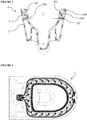
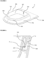
- A WC pan flushing system developed to fulfill the objective of the present invention is illustrated in the accompanying figures wherein:
- Figure 1
- is a perspective view of the WC pan flushing system.
- Figure 2
- is a perspective view of the main part.
- Figure 3
- is a front sectional view of the WC pan flushing system.
- Figure 4
- is a top view of the water flow in the WC pan flushing system.
- Figure 5
- is a perspective view of the upper part.
- Figure 6
- is a detailed sectional view of the WC pan flushing system.
- The components in the figures are given reference numbers as follows:
- 1. WC pan flushing system
- 2. Main part
- 201. WC pan chamber inlet
- 202. WC pan chamber
- 203. Lower surface
- 204. WC pan water inlet hole
- 205. Set
- 206. Guiding rib
- 207. First edge line curve
- 208. First side surface
- 209. Main part adhesion surface
- 3. Upper part
- 301. Upper part adhesion surface
- 302. Second side surface
- 303. Abutment surface
- 304. Pressing surface
- 305. Horizontal surface
- 306. Second edge line curve
- 307. Inner surface
- 308. Cleansing hole
- 4. Flushing channel
- 5. Flow channel
- A WC pan flushing system, which regulates flow of the flushing function and which also prevents overflow of the flushing water in the WC pan and enables the WC pan flushing channels to be easily cleaned, is proposed in accordance with the technical features of
independent claim 1. - The WC pan flushing system (1) of the present invention basically comprises two main systems, namely the main part (2) and the upper part (3). The main part (2) has a WC pan structure and is connected onto the drain. There is provided a WC pan chamber inlet (201), which constitutes the drain part of the WC pan, on the main part (2); and the drain water is collected in the WC pan chamber inlet (201). A WC pan chamber (202) is provided which serves as a funnel with its curved structure to enable the water to flow towards the WC pan chamber inlet (201). On the upper end part of the WC pan chamber (202), there is a lower surface (203) which preferably extends parallel to the ground plane. There is a WC pan water inlet hole (204) provided on the WC pan chamber (202) and the WC pan is cleaned with the water entering through the WC pan water inlet hole (204). A set (205) is provided on the lower surface (203) and in front of the water inlet hole (204) such that it will serve as a barrier against the flow of the entering water. Guiding ribs (206), which are located on the lower surface (203) and the set (205), are used to guide the water entering through the water inlet hole (204) towards the WC pan chamber (202). By means of the guiding ribs (206), the water is enabled to move more easily in the WC pan chamber (202) and flushing/cleaning process is performed with a smaller amount of water. A first edge line curve (207) in the form of an arc is located on the side corner of the part of the lower surface (203) facing the WC pan chamber inlet (201). A first side surface (208), which extends upwards in the form of a wall, is located on the other edge of the lower surface (203). A main part adhesion surface (209) is placed on the side surface of the first side surface (208) such that it is preferably parallel to the ground plane.
- An upper part (3) is placed on the main part (2). An upper part adhesion surface (301) is located so as to correspond to the main part adhesion surface (209). A second side surface (302) extends from the upper part adhesion surface (301) preferably parallel to the main part (2) first side surface (208). An abutment surface (303) extends on the end edge of the second side surface (302) preferably parallel to the ground plane. The abutment surface (303) is placed on the guiding ribs (206). The guiding ribs (206) carry the abutment surface (303). A pressing surface (304) is placed on the end edge of the abutment surface (301) and the pressing surface (304) extends towards the WC pan chamber (202). A horizontal surface (305) is located on the end edge of the pressing surface (303) and the horizontal surface (305) is preferably disposed parallel to the ground plane. A second edge line curve (306) is located on the side corner of the part of the horizontal surface (305) facing the WC pan chamber inlet (201), and the second edge line curve (306) is in the form of an arc. An inner surface (307) extends from the second edge line curve (306) towards the upper part adhesion surface (301). A cleansing hole (308) is drilled on the inner surface (307) and the second side surface (302). A flushing channel (4) in the form of a hollow is located between the first side surface (208) and the second side surface (302) for passage of the water. A flow channel (5) in the form of a hollow is located between the horizontal surface (305) and the lower surface (203) for passage of the water.
- The flushing channel (4) is a closed structure obtained by molding the WC pan as two pieces, namely the main part (2) and the upper part (3), during the production process and then assembling thereof.
- By means of the flushing channel (4), the flushing water coming from the WC pan water inlet hole (204) hits the set (205) located on the lower surface (203) and it is enabled to be homogeneously spread on the lower surface (203). The water homogenously spread on the lower surface (203) enters into the flushing channel (4) located between the first side surface (204) and the second side surface (302). The water in the flushing channel (4) is directed towards the WC pan chamber (202) through the guiding ribs (206). This way, the flow is enabled to be controlled. The water passing through the guiding ribs (206) is directed to a narrow flow channel (5) provided between the horizontal surface (305) and the lower surface (203). Since the flow channel (5) between the horizontal surface (305) and the lower surface (203) is narrow, it enables the water to flow towards the WC pan chamber (202) with high pressure. In order to prevent the water flowing towards the WC pan chamber (202) with high pressure from overflowing out of the WC pan, the first edge line curve (207) located at the end part of the lower surface (203) and the second edge line curve (306) located on the horizontal surface (305) enable the water to flow towards the WC pan chamber (202) with high pressure. The inner surface (307) and the WC pan chamber (202) surfaces are positioned close to each other; by this means, cleaning the flow channel (5) through which the water flows towards the WC pan chamber (202) can be easily carried out by one person.
- A WC pan system (1) is produced by assembling the main part (2) and the upper parts (3) which are molded separately. Adhesion process, which is a ceramic production method, is performed by using slurry, which is a ceramic raw material, as an adhesive in the phase wherein the molded parts are yet defined as "greenware" and shaping is possible. When the upper part (3) and the main part (2) of the WC pan are assembled, the upper part adhesion surface (301) abuts onto the main part adhesion surface (209) thereby forming the hollow of the flushing channel (4). The upper part (3) fits onto the guiding ribs (206) and enables the structure of the WC pan flushing system (1) to be more rigid. The flushing channel (4) is formed by connection of the first side surface (208) and lower surface (203) of the main part (2), which restrict the flushing channel (4) hollow, with the surfaces of the upper part (3), which restrict the flushing channel (4).
- The flushing channel (4) guides the water towards the WC pan chamber (202) in a desired manner by means of the guiding ribs (206) which are positioned in the hollow of the flushing channel (4) formed on the main part (2). The guiding ribs (206) guiding the water flow in the flushing channel (4), are positioned on the surface which is located on the main part (2) and which forms the lower surface (203) of the flushing channel (4).
- When the main part (2) and the upper part (3) of the WC pan are assembled, the WC pan chamber (202) and the inner surface (301) of the upper part (3) that complements the WC pan chamber (202) are approximately aligned, and a circumferential (all-around) flow channel (5) is formed between these two parts. The flow channel (5) enables the water directed through the flushing channel (4) to be output to the WC pan chamber (202) under certain conditions.
- The purpose of the flushing water is to deliver the waste in the WC pan chamber (202) bottom part/siphon structure inlet, i.e. WC pan chamber inlet (201), to the drain line in the shortest possible time. In order to achieve this, a part of the flushing water is required to be delivered to the WC pan chamber (202) bottom part/siphon structure inlet, i.e. WC pan chamber inlet (201), without losing its speed. At the same time in the function tests, almost the entire surface area forming the WC pan chamber (202) is enabled to be flushed at a certain ratio.
- During the flushing function, providing different flow models at the same time is related to the water passing through the flushing channel (4) being directed to the WC pan chamber (202) by means of the structural details of the circumferential flow channel (5). For this, the water, whose flow model and direction is regulated by being passed through the flushing channel (4) and the guiding ribs (206), passes through the final hollow at the end of the flushing channel (4) and exits the circumferential flow channel (5) by a specific velocity vector. When the radius (rR), i.e. the second edge line curve (306), located circumferentially at the edge of the second side surface (302) of the flow channel (5) on the upper part (3) is kept in minimum sizes allowed by the ceramic production methods, the water is prevented from getting scattered by holding onto the curved surface (306) due to adhesion force. A part of the water output from the flow channel (5) by a specific velocity via a velocity vector (V(FR)) horizontally acquires a flow (FR) slope under the influence of gravity (Fg). In this case, with the FR flow model, a part of the water is directly guided to the WC pan chamber (202) bottom part/siphon structure inlet, i.e. WC pan chamber inlet (201). This flow model can be changed as desired by changing/enlarging the width of the circumferential flow channel (5) at certain parts thereof. By providing this flow model (FR), the water is prevented from splashing out of the WC pan.
- The rounding (rB), i.e. the first edge line curve (207), formed at the edge line where the WC pan chamber (202) is connected with the circumferential flow channel (5) has an important function for flushing of the WC pan chamber (202). The first edge line curve (rB) (207), by making use of the adhesion force of the water, provides the flow (FB) that is formed as a result of the amount of water in direct proportion to the size of the first edge line curve (rB) (207) following the WC pan chamber (202) surface.
- By means of simultaneous control of these different flow types, the waste in the WC pan chamber (201) is enabled to be discharged within the shortest time possible, and water conservation is obtained due to use of smaller amount of water during the function and the entire WC pan chamber is enabled to be flushed.
- The WC pan water inlet hole (204), through which the water first enters into the WC pan flushing channel (4), is the area where the velocity of the water is the highest. This area is the most suitable area through which direct flow towards the WC pan chamber (202) bottom part can be enabled during flushing without splashing water out of the WC pan. However, a set (205), whose form and details may vary depending on different chamber forms, is formed at this area for controlling the velocity and flow rate of the water.
Claims (5)
- A WC pan flushing system, which regulates flow of water during flushing function and which also prevents overflow of the flushing water in the WC pan and enables the WC pan flushing channels to be easily cleaned, comprising- at least one main part (2) which has a structure of a WC pan and is connected onto a drain,- at least one WC pan chamber inlet (201) which forms the drain of the WC pan and in which the drain water is collected,- at least one WC pan chamber (202) which has a curved structure enabling flush water to go to the WC pan chamber inlet (201),wherein the WC pan further comprises:- at least one lower surface (203) which is located on the upper end point of the WC pan chamber (202),- at least one WC pan water inlet hole (204) which is provided on the WC pan chamber (202) and which enables the water to enter the WC pan chamber (202),- at least one set (205) which is located on the lower surface (203) and in front of the WC pan water inlet hole (204) thereby serving as a barrier in front of the water entering the WC pan chamber (202) through the WC pan water inlet hole (204),- at least one guiding rib (206), which is placed on the lower surface (203) or the set (205), and which enables to guide the water entering through the WC pan water inlet hole (204) towards the WC pan chamber (202),- at least one first edge line curve (207) in the form of an arc located on the side corner part of the lower surface (203), the side corner part facing the WC pan chamber inlet (201),- at least one first side surface (208) which extends upwards in the form of a wall on the other side of the lower surface (203), opposite the first edge line curve (207),characterised by:- at least one main part adhesion surface (209) which extends from the end point of the first side surface (208),- at least one upper part (3) which is placed on the main part (2), the at least one upper part (3) having at least one upper part adhesion surface (301) which is located so as to correspond to the main part (2) adhesion surface (209) and adhered thereto when assembling the WC pan from the at least main part (2) and the at least one upper part (3), the at least one upper part (3) further comprising:- at least one second side surface (302) which extends from the at least one upper part adhesion surface (301) such that it is parallel to the main part (2) first side surface (208),- the at least one second side surface (302) comprising at least one abutment surface (303) which extends at the lower end edge of the second side surface (302) and is placed on the at least one guiding rib (206),- at least one pressing surface (304) extending from the end edge of the abutment surface (303) towards the lower surface (203) of the WC pan chamber (202),- at least one horizontal surface (305) which is located on the end edge of the pressing surface (303) and extends downward from the end point thereof,- at least one second edge line curve (306) in the form of an arc which is located on the side corner part of the horizontal surface (305) facing the WC pan chamber inlet (201),- at least one inner surface (307) which extends from the second edge line curve (306) towards the upper surface of the at least one upper part (3),- at least one cleansing hole (308) which is drilled on the inner surface (307) and the second side surface (302),
wherein- at least one flushing channel (4) in the form of a hollow is located between the first side surface (208) in form of a wall and facing the WC pan chamber (202) and the second side surface (302) facing outside the WC pan chamber (202), for passage of flushing water, and wherein- at least one flow channel (5) in the form of a hollow is located between the horizontal surface (305) and the lower surface (203) for passage of the water. - A WC pan flushing system (1) according to Claim 1, wherein the at least one flow channel (5) is a narrow area between the at least one inner surface (307) and the at least one first edge line curve (207) of the WC pan chamber (202), enabling flush water to flow towards the WC pan chamber (202) with high pressure.
- A WC pan flushing system (1) according to Claim 1, wherein the at least one main part (2) and the at least one upper part (3) are produced in separate molds before being assembled to each other by adhering.
- A WC pan flushing system (1) according to Claim 1, wherein the at least one flow channel (5) which is formed circumferentially of the WC pan, between the WC pan chamber (202) and the inner surface (301) of the upper part (3).
- A WC pan flushing system (202) according to Claim 1, wherein the at least one flow channel (5) enables flushing water to be directed through the flushing channel (4) and to be output to the WC pan chamber (202).
Applications Claiming Priority (1)
| Application Number | Priority Date | Filing Date | Title |
|---|---|---|---|
| TR2016/12657A TR201612657A2 (en) | 2016-09-07 | 2016-09-07 | A TOILET WASHING SYSTEM |
Publications (2)
| Publication Number | Publication Date |
|---|---|
| EP3293316A1 EP3293316A1 (en) | 2018-03-14 |
| EP3293316B1 true EP3293316B1 (en) | 2019-12-11 |
Family
ID=59829118
Family Applications (1)
| Application Number | Title | Priority Date | Filing Date |
|---|---|---|---|
| EP17186195.8A Active EP3293316B1 (en) | 2016-09-07 | 2017-08-14 | A wc pan flushing system |
Country Status (2)
| Country | Link |
|---|---|
| EP (1) | EP3293316B1 (en) |
| TR (1) | TR201612657A2 (en) |
Families Citing this family (1)
| Publication number | Priority date | Publication date | Assignee | Title |
|---|---|---|---|---|
| CN112523317B (en) * | 2020-12-18 | 2025-05-30 | 箭牌家居集团股份有限公司 | A squat toilet with good flushing effect |
Family Cites Families (10)
| Publication number | Priority date | Publication date | Assignee | Title |
|---|---|---|---|---|
| US1435644A (en) | 1922-01-14 | 1922-11-14 | Thomas Maddock S Sons Co | Sanitary bowl |
| US1957809A (en) * | 1932-10-15 | 1934-05-08 | Frederick A Schossow | Toilet bowl |
| US6428643B1 (en) | 1999-11-19 | 2002-08-06 | Kohler Co. | Method and apparatus for casting a plumbing fixture |
| US7661153B2 (en) * | 2002-09-03 | 2010-02-16 | Toto Ltd. | Flush toilet |
| JP6246453B2 (en) * | 2011-08-24 | 2017-12-13 | Toto株式会社 | Flush toilet |
| DE502011005882C5 (en) | 2011-12-14 | 2026-03-26 | Geberit International Ag | Water closet |
| WO2013126921A2 (en) | 2012-02-24 | 2013-08-29 | As Ip Holdco, Llc | Rimless toilet |
| CN103510601B (en) * | 2013-10-24 | 2015-05-20 | 佛山市浪鲸洁具有限公司 | Closestool base |
| DE102014104500A1 (en) | 2013-12-19 | 2014-06-26 | Villeroy & Boch Ag | Toilet bowl for toilet, has manifold apron that is arranged in front of inflow aperture of bowl edge to form baffle plate, and first and second walls are set with laterally and downwardly open hollow channel to limit water flow |
| GB2528324B (en) | 2014-07-18 | 2017-11-01 | Ideal Standard (Uk) Ltd | Toilet bowl unit |
-
2016
- 2016-09-07 TR TR2016/12657A patent/TR201612657A2/en unknown
-
2017
- 2017-08-14 EP EP17186195.8A patent/EP3293316B1/en active Active
Non-Patent Citations (1)
| Title |
|---|
| None * |
Also Published As
| Publication number | Publication date |
|---|---|
| EP3293316A1 (en) | 2018-03-14 |
| TR201612657A2 (en) | 2018-03-21 |
Similar Documents
| Publication | Publication Date | Title |
|---|---|---|
| US10233627B2 (en) | Rimless toilet | |
| RU2313451C2 (en) | Device and method for gypsum suspension fractionating and method for gypsum board production | |
| CN108474198B (en) | Faucet including an open waterway | |
| CA3066148C (en) | Cantilevered faucet spout | |
| CN106801461A (en) | Non-flanged type toilet | |
| US20120325928A1 (en) | Jet regulator | |
| US20190153713A1 (en) | Flush toilet | |
| JP6071112B2 (en) | Flush toilet | |
| TW201013023A (en) | Food preparation sink | |
| WO2019185811A1 (en) | Wash stand | |
| EP2986787A1 (en) | Toilet with personal shower integrated into flushing water distributor | |
| US4930167A (en) | Toilet with vortex flushing action | |
| AU2012351164A1 (en) | Water closet | |
| CN108026720A (en) | The manufacture method of water closet and closestool base | |
| EP3336267A1 (en) | Flush toilet device | |
| WO2019052456A1 (en) | Toilet flush structure with double flush water paths | |
| EP3293316A1 (en) | A wc pan flushing system | |
| CN101489688B (en) | Die with insert and gas purging method for die | |
| JP2018003262A (en) | Flush toilet bowl | |
| EP3394357B1 (en) | A flushing apparatus | |
| JP6222842B2 (en) | Toilet body | |
| JP2006089971A (en) | Western style flush toilet bowl | |
| CN107761835A (en) | Portable integrated shower bath | |
| WO2016179228A1 (en) | Anto-overflow toilet | |
| EP0392997A2 (en) | Sanitary apparatus having the function of a W.C. bowl and of a bidet as well, and providing a continuous flush when using the bowl |
Legal Events
| Date | Code | Title | Description |
|---|---|---|---|
| PUAI | Public reference made under article 153(3) epc to a published international application that has entered the european phase |
Free format text: ORIGINAL CODE: 0009012 |
|
| STAA | Information on the status of an ep patent application or granted ep patent |
Free format text: STATUS: THE APPLICATION HAS BEEN PUBLISHED |
|
| AK | Designated contracting states |
Kind code of ref document: A1 Designated state(s): AL AT BE BG CH CY CZ DE DK EE ES FI FR GB GR HR HU IE IS IT LI LT LU LV MC MK MT NL NO PL PT RO RS SE SI SK SM TR |
|
| AX | Request for extension of the european patent |
Extension state: BA ME |
|
| STAA | Information on the status of an ep patent application or granted ep patent |
Free format text: STATUS: REQUEST FOR EXAMINATION WAS MADE |
|
| 17P | Request for examination filed |
Effective date: 20180730 |
|
| RBV | Designated contracting states (corrected) |
Designated state(s): AL AT BE BG CH CY CZ DE DK EE ES FI FR GB GR HR HU IE IS IT LI LT LU LV MC MK MT NL NO PL PT RO RS SE SI SK SM TR |
|
| GRAP | Despatch of communication of intention to grant a patent |
Free format text: ORIGINAL CODE: EPIDOSNIGR1 |
|
| STAA | Information on the status of an ep patent application or granted ep patent |
Free format text: STATUS: GRANT OF PATENT IS INTENDED |
|
| RIC1 | Information provided on ipc code assigned before grant |
Ipc: E03D 11/08 20060101AFI20190606BHEP |
|
| INTG | Intention to grant announced |
Effective date: 20190704 |
|
| RIN1 | Information on inventor provided before grant (corrected) |
Inventor name: SUNAR, ALDONAT Inventor name: DOGAN, ZAFER |
|
| GRAS | Grant fee paid |
Free format text: ORIGINAL CODE: EPIDOSNIGR3 |
|
| GRAA | (expected) grant |
Free format text: ORIGINAL CODE: 0009210 |
|
| STAA | Information on the status of an ep patent application or granted ep patent |
Free format text: STATUS: THE PATENT HAS BEEN GRANTED |
|
| AK | Designated contracting states |
Kind code of ref document: B1 Designated state(s): AL AT BE BG CH CY CZ DE DK EE ES FI FR GB GR HR HU IE IS IT LI LT LU LV MC MK MT NL NO PL PT RO RS SE SI SK SM TR |
|
| REG | Reference to a national code |
Ref country code: GB Ref legal event code: FG4D |
|
| REG | Reference to a national code |
Ref country code: CH Ref legal event code: EP |
|
| REG | Reference to a national code |
Ref country code: AT Ref legal event code: REF Ref document number: 1212310 Country of ref document: AT Kind code of ref document: T Effective date: 20191215 |
|
| REG | Reference to a national code |
Ref country code: DE Ref legal event code: R096 Ref document number: 602017009539 Country of ref document: DE |
|
| REG | Reference to a national code |
Ref country code: IE Ref legal event code: FG4D |
|
| REG | Reference to a national code |
Ref country code: NL Ref legal event code: MP Effective date: 20191211 |
|
| REG | Reference to a national code |
Ref country code: LT Ref legal event code: MG4D |
|
| PG25 | Lapsed in a contracting state [announced via postgrant information from national office to epo] |
Ref country code: BG Free format text: LAPSE BECAUSE OF FAILURE TO SUBMIT A TRANSLATION OF THE DESCRIPTION OR TO PAY THE FEE WITHIN THE PRESCRIBED TIME-LIMIT Effective date: 20200311 Ref country code: FI Free format text: LAPSE BECAUSE OF FAILURE TO SUBMIT A TRANSLATION OF THE DESCRIPTION OR TO PAY THE FEE WITHIN THE PRESCRIBED TIME-LIMIT Effective date: 20191211 Ref country code: NO Free format text: LAPSE BECAUSE OF FAILURE TO SUBMIT A TRANSLATION OF THE DESCRIPTION OR TO PAY THE FEE WITHIN THE PRESCRIBED TIME-LIMIT Effective date: 20200311 Ref country code: GR Free format text: LAPSE BECAUSE OF FAILURE TO SUBMIT A TRANSLATION OF THE DESCRIPTION OR TO PAY THE FEE WITHIN THE PRESCRIBED TIME-LIMIT Effective date: 20200312 Ref country code: LT Free format text: LAPSE BECAUSE OF FAILURE TO SUBMIT A TRANSLATION OF THE DESCRIPTION OR TO PAY THE FEE WITHIN THE PRESCRIBED TIME-LIMIT Effective date: 20191211 Ref country code: SE Free format text: LAPSE BECAUSE OF FAILURE TO SUBMIT A TRANSLATION OF THE DESCRIPTION OR TO PAY THE FEE WITHIN THE PRESCRIBED TIME-LIMIT Effective date: 20191211 Ref country code: LV Free format text: LAPSE BECAUSE OF FAILURE TO SUBMIT A TRANSLATION OF THE DESCRIPTION OR TO PAY THE FEE WITHIN THE PRESCRIBED TIME-LIMIT Effective date: 20191211 |
|
| PG25 | Lapsed in a contracting state [announced via postgrant information from national office to epo] |
Ref country code: RS Free format text: LAPSE BECAUSE OF FAILURE TO SUBMIT A TRANSLATION OF THE DESCRIPTION OR TO PAY THE FEE WITHIN THE PRESCRIBED TIME-LIMIT Effective date: 20191211 Ref country code: HR Free format text: LAPSE BECAUSE OF FAILURE TO SUBMIT A TRANSLATION OF THE DESCRIPTION OR TO PAY THE FEE WITHIN THE PRESCRIBED TIME-LIMIT Effective date: 20191211 |
|
| PG25 | Lapsed in a contracting state [announced via postgrant information from national office to epo] |
Ref country code: AL Free format text: LAPSE BECAUSE OF FAILURE TO SUBMIT A TRANSLATION OF THE DESCRIPTION OR TO PAY THE FEE WITHIN THE PRESCRIBED TIME-LIMIT Effective date: 20191211 |
|
| PG25 | Lapsed in a contracting state [announced via postgrant information from national office to epo] |
Ref country code: ES Free format text: LAPSE BECAUSE OF FAILURE TO SUBMIT A TRANSLATION OF THE DESCRIPTION OR TO PAY THE FEE WITHIN THE PRESCRIBED TIME-LIMIT Effective date: 20191211 Ref country code: NL Free format text: LAPSE BECAUSE OF FAILURE TO SUBMIT A TRANSLATION OF THE DESCRIPTION OR TO PAY THE FEE WITHIN THE PRESCRIBED TIME-LIMIT Effective date: 20191211 Ref country code: PT Free format text: LAPSE BECAUSE OF FAILURE TO SUBMIT A TRANSLATION OF THE DESCRIPTION OR TO PAY THE FEE WITHIN THE PRESCRIBED TIME-LIMIT Effective date: 20200506 Ref country code: RO Free format text: LAPSE BECAUSE OF FAILURE TO SUBMIT A TRANSLATION OF THE DESCRIPTION OR TO PAY THE FEE WITHIN THE PRESCRIBED TIME-LIMIT Effective date: 20191211 Ref country code: CZ Free format text: LAPSE BECAUSE OF FAILURE TO SUBMIT A TRANSLATION OF THE DESCRIPTION OR TO PAY THE FEE WITHIN THE PRESCRIBED TIME-LIMIT Effective date: 20191211 Ref country code: EE Free format text: LAPSE BECAUSE OF FAILURE TO SUBMIT A TRANSLATION OF THE DESCRIPTION OR TO PAY THE FEE WITHIN THE PRESCRIBED TIME-LIMIT Effective date: 20191211 |
|
| PG25 | Lapsed in a contracting state [announced via postgrant information from national office to epo] |
Ref country code: IS Free format text: LAPSE BECAUSE OF FAILURE TO SUBMIT A TRANSLATION OF THE DESCRIPTION OR TO PAY THE FEE WITHIN THE PRESCRIBED TIME-LIMIT Effective date: 20200411 Ref country code: SK Free format text: LAPSE BECAUSE OF FAILURE TO SUBMIT A TRANSLATION OF THE DESCRIPTION OR TO PAY THE FEE WITHIN THE PRESCRIBED TIME-LIMIT Effective date: 20191211 Ref country code: SM Free format text: LAPSE BECAUSE OF FAILURE TO SUBMIT A TRANSLATION OF THE DESCRIPTION OR TO PAY THE FEE WITHIN THE PRESCRIBED TIME-LIMIT Effective date: 20191211 |
|
| REG | Reference to a national code |
Ref country code: DE Ref legal event code: R097 Ref document number: 602017009539 Country of ref document: DE |
|
| REG | Reference to a national code |
Ref country code: AT Ref legal event code: MK05 Ref document number: 1212310 Country of ref document: AT Kind code of ref document: T Effective date: 20191211 |
|
| PLBE | No opposition filed within time limit |
Free format text: ORIGINAL CODE: 0009261 |
|
| STAA | Information on the status of an ep patent application or granted ep patent |
Free format text: STATUS: NO OPPOSITION FILED WITHIN TIME LIMIT |
|
| PG25 | Lapsed in a contracting state [announced via postgrant information from national office to epo] |
Ref country code: DK Free format text: LAPSE BECAUSE OF FAILURE TO SUBMIT A TRANSLATION OF THE DESCRIPTION OR TO PAY THE FEE WITHIN THE PRESCRIBED TIME-LIMIT Effective date: 20191211 |
|
| 26N | No opposition filed |
Effective date: 20200914 |
|
| PG25 | Lapsed in a contracting state [announced via postgrant information from national office to epo] |
Ref country code: AT Free format text: LAPSE BECAUSE OF FAILURE TO SUBMIT A TRANSLATION OF THE DESCRIPTION OR TO PAY THE FEE WITHIN THE PRESCRIBED TIME-LIMIT Effective date: 20191211 Ref country code: SI Free format text: LAPSE BECAUSE OF FAILURE TO SUBMIT A TRANSLATION OF THE DESCRIPTION OR TO PAY THE FEE WITHIN THE PRESCRIBED TIME-LIMIT Effective date: 20191211 |
|
| PG25 | Lapsed in a contracting state [announced via postgrant information from national office to epo] |
Ref country code: IT Free format text: LAPSE BECAUSE OF FAILURE TO SUBMIT A TRANSLATION OF THE DESCRIPTION OR TO PAY THE FEE WITHIN THE PRESCRIBED TIME-LIMIT Effective date: 20191211 |
|
| PG25 | Lapsed in a contracting state [announced via postgrant information from national office to epo] |
Ref country code: PL Free format text: LAPSE BECAUSE OF FAILURE TO SUBMIT A TRANSLATION OF THE DESCRIPTION OR TO PAY THE FEE WITHIN THE PRESCRIBED TIME-LIMIT Effective date: 20191211 |
|
| PG25 | Lapsed in a contracting state [announced via postgrant information from national office to epo] |
Ref country code: MC Free format text: LAPSE BECAUSE OF FAILURE TO SUBMIT A TRANSLATION OF THE DESCRIPTION OR TO PAY THE FEE WITHIN THE PRESCRIBED TIME-LIMIT Effective date: 20191211 |
|
| REG | Reference to a national code |
Ref country code: CH Ref legal event code: PL |
|
| PG25 | Lapsed in a contracting state [announced via postgrant information from national office to epo] |
Ref country code: LU Free format text: LAPSE BECAUSE OF NON-PAYMENT OF DUE FEES Effective date: 20200814 Ref country code: LI Free format text: LAPSE BECAUSE OF NON-PAYMENT OF DUE FEES Effective date: 20200831 Ref country code: CH Free format text: LAPSE BECAUSE OF NON-PAYMENT OF DUE FEES Effective date: 20200831 |
|
| REG | Reference to a national code |
Ref country code: BE Ref legal event code: MM Effective date: 20200831 |
|
| PG25 | Lapsed in a contracting state [announced via postgrant information from national office to epo] |
Ref country code: FR Free format text: LAPSE BECAUSE OF NON-PAYMENT OF DUE FEES Effective date: 20200831 |
|
| PG25 | Lapsed in a contracting state [announced via postgrant information from national office to epo] |
Ref country code: BE Free format text: LAPSE BECAUSE OF NON-PAYMENT OF DUE FEES Effective date: 20200831 Ref country code: IE Free format text: LAPSE BECAUSE OF NON-PAYMENT OF DUE FEES Effective date: 20200814 |
|
| GBPC | Gb: european patent ceased through non-payment of renewal fee |
Effective date: 20210814 |
|
| PG25 | Lapsed in a contracting state [announced via postgrant information from national office to epo] |
Ref country code: TR Free format text: LAPSE BECAUSE OF FAILURE TO SUBMIT A TRANSLATION OF THE DESCRIPTION OR TO PAY THE FEE WITHIN THE PRESCRIBED TIME-LIMIT Effective date: 20191211 Ref country code: MT Free format text: LAPSE BECAUSE OF FAILURE TO SUBMIT A TRANSLATION OF THE DESCRIPTION OR TO PAY THE FEE WITHIN THE PRESCRIBED TIME-LIMIT Effective date: 20191211 Ref country code: CY Free format text: LAPSE BECAUSE OF FAILURE TO SUBMIT A TRANSLATION OF THE DESCRIPTION OR TO PAY THE FEE WITHIN THE PRESCRIBED TIME-LIMIT Effective date: 20191211 |
|
| PG25 | Lapsed in a contracting state [announced via postgrant information from national office to epo] |
Ref country code: MK Free format text: LAPSE BECAUSE OF FAILURE TO SUBMIT A TRANSLATION OF THE DESCRIPTION OR TO PAY THE FEE WITHIN THE PRESCRIBED TIME-LIMIT Effective date: 20191211 |
|
| PG25 | Lapsed in a contracting state [announced via postgrant information from national office to epo] |
Ref country code: GB Free format text: LAPSE BECAUSE OF NON-PAYMENT OF DUE FEES Effective date: 20210814 |
|
| PGFP | Annual fee paid to national office [announced via postgrant information from national office to epo] |
Ref country code: DE Payment date: 20250827 Year of fee payment: 9 |