EP3293045A1 - Simultaneously rotatable and translatable vehicle head restraint - Google Patents
Simultaneously rotatable and translatable vehicle head restraint Download PDFInfo
- Publication number
- EP3293045A1 EP3293045A1 EP17190521.9A EP17190521A EP3293045A1 EP 3293045 A1 EP3293045 A1 EP 3293045A1 EP 17190521 A EP17190521 A EP 17190521A EP 3293045 A1 EP3293045 A1 EP 3293045A1
- Authority
- EP
- European Patent Office
- Prior art keywords
- head restraint
- locking mechanism
- assembly
- cross member
- vehicle
- Prior art date
- Legal status (The legal status is an assumption and is not a legal conclusion. Google has not performed a legal analysis and makes no representation as to the accuracy of the status listed.)
- Withdrawn
Links
Images


Classifications
-
- B—PERFORMING OPERATIONS; TRANSPORTING
- B60—VEHICLES IN GENERAL
- B60N—SEATS SPECIALLY ADAPTED FOR VEHICLES; VEHICLE PASSENGER ACCOMMODATION NOT OTHERWISE PROVIDED FOR
- B60N2/00—Seats specially adapted for vehicles; Arrangement or mounting of seats in vehicles
- B60N2/80—Head-rests
- B60N2/806—Head-rests movable or adjustable
- B60N2/838—Tiltable
- B60N2/853—Tiltable characterised by their adjusting mechanisms, e.g. electric motors
-
- B—PERFORMING OPERATIONS; TRANSPORTING
- B60—VEHICLES IN GENERAL
- B60N—SEATS SPECIALLY ADAPTED FOR VEHICLES; VEHICLE PASSENGER ACCOMMODATION NOT OTHERWISE PROVIDED FOR
- B60N2/00—Seats specially adapted for vehicles; Arrangement or mounting of seats in vehicles
- B60N2/80—Head-rests
- B60N2/806—Head-rests movable or adjustable
- B60N2/838—Tiltable
- B60N2/841—Tiltable characterised by their locking devices
- B60N2/844—Release mechanisms, e.g. buttons
-
- B—PERFORMING OPERATIONS; TRANSPORTING
- B60—VEHICLES IN GENERAL
- B60N—SEATS SPECIALLY ADAPTED FOR VEHICLES; VEHICLE PASSENGER ACCOMMODATION NOT OTHERWISE PROVIDED FOR
- B60N2/00—Seats specially adapted for vehicles; Arrangement or mounting of seats in vehicles
- B60N2/80—Head-rests
- B60N2/806—Head-rests movable or adjustable
- B60N2/838—Tiltable
- B60N2/841—Tiltable characterised by their locking devices
- B60N2/847—Tiltable characterised by their locking devices with stepwise positioning
-
- B—PERFORMING OPERATIONS; TRANSPORTING
- B60—VEHICLES IN GENERAL
- B60N—SEATS SPECIALLY ADAPTED FOR VEHICLES; VEHICLE PASSENGER ACCOMMODATION NOT OTHERWISE PROVIDED FOR
- B60N2/00—Seats specially adapted for vehicles; Arrangement or mounting of seats in vehicles
- B60N2/80—Head-rests
- B60N2/806—Head-rests movable or adjustable
- B60N2/868—Head-rests movable or adjustable providing a lateral movement parallel to the occupant's shoulder line
Abstract
Description
- This patent application claims the benefit of priority to
U.S. Provisional Patent Application Serial No. 62/393,890, filed September 13, 2016 - The subject matter disclosed herein relates to head restraints and, more particularly, to a vehicle head restraint that is simultaneously rotatable and translatable.
- Many vehicles, such as automobiles, include a headrest or head restraint atop an occupant's seat and in a position adjacent the occupant's head. Head restraints are typically cushioned for comfort, are height adjustable, and most are commonly finished in the same material as the rest of the seat.
- According to one aspect of the invention, a vehicle head restraint assembly includes a base portion coupleable to a vehicle seat back, the base portion including a cross member portion. Also included is a head restraint operatively coupled to the cross member portion and rotatable about the cross member portion. Further included is a helical drive assembly for translating the head restraint during rotation of the head restraint.
- According to another aspect of the invention, a vehicle head restraint assembly includes a head restraint that is simultaneously rotatable and translatable in a cross-car direction of a vehicle.
- The subject matter, which is regarded as the invention, is particularly pointed out and distinctly claimed in the claims at the conclusion of the specification. The foregoing and other features, and advantages of the invention are apparent from the following detailed description taken in conjunction with the accompanying drawings in which:
-
FIG. 1 is a perspective view of a head restraint assembly; -
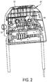
FIG. 2 is a perspective view of the head restraint assembly in an upright position; -
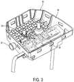
FIG. 3 is a perspective view of the head restraint assembly in a downwardly rotated position; -
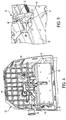
FIG. 4 is a perspective view of the head restraint assembly illustrating an internal cavity; -
FIG. 5 is an enlarged perspective view of a lock mechanism of the head restraint assembly; -
FIG. 6 is a perspective view of the head restraint assembly according to an aspect of the disclosure; and -
FIG. 7 is a perspective view of a helical drive of the head restraint assembly. - The detailed description explains embodiments of the invention, together with advantages and features, by way of example with reference to the drawings.
- Referring to
FIG. 1 , ahead restraint assembly 10 is depicted. Thehead restraint assembly 10 includes a base portion 14 (which may also be referred to as an "armature") that is mountable to a vehicle seat (not shown), and, more specifically, to the upper portion of the seatback of the vehicle seat. In the illustrated embodiment, thebase portion 14 is formed from a single piece of metal and includes two parallelpost portions 18 that are mounted, or mountable, to the top of the seatback of the vehicle seat, as understood by those skilled in the art. Each of thepost portions 18 includes a respective elongated, straight portion. Each of the straight portions extends into a respective hole formed in the top of the seatback to attach thehead restraint assembly 10 to the vehicle seat. - The
head restraint assembly 10 is illustrated without a cover to show components partially or completely disposed therein. As shown, thebase portion 14 also includes across member portion 26 that interconnects the twopost portions 18. Thecross member portion 26 extends substantially transversely relative to thepost portions 18. For example, when thebase portion 14 is connected to a vehicle seat, thepost portions 18 are generally vertical, and thecross member portion 26 is generally horizontal. - The
head restraint assembly 10 further includes ahead restraint 40 operatively connected to thebase portion 14. In the embodiment depicted, thehead restraint 40 includes ahousing 44 that provides rigid structure to thehead restraint 40. A head restraint cushion is comprised of soft foam or a like material to provide a cushion between the head of a human occupant of the vehicle seat and thehead restraint housing 44. The head restraint cover covers at least part of the cushion and the housing to enhance the aesthetics of the head restraint. Exemplary cover materials include cloth, vinyl, leather, etc. - The
housing 44 at least partially defines aninternal cavity 12 therein. Thehousing 44 may be formed of numerous contemplated materials. In one embodiment, thehousing 44 is formed of plastic. Two apertures are defined by the cover and/or thehousing 44 and are each configured to receive one of theposts 18. Theposts 18 of the base portion extend through a respective one of the apertures to enter theinternal cavity 12. Thecross member portion 26 extends through theinternal cavity 12. - Referring to
FIGS. 2 and3 , a portion of thehousing 44 is removed to illustrate internal mechanisms and sub-assemblies of thehead restraint 40. As shown, thehead restraint 40 is pivotable about thecross member portion 26 between a substantially upright position (FIG. 2 ) and a downwardly rotated position (FIG. 3 ). The upright position is defined by a range of angular positions that are closer to a vertical orientation of thehead restraint 40 than a horizontal orientation of thehead restraint 40. The downward position is defined by a range of angular positions that are closer to the horizontal orientation of thehead restraint 40 than the vertical orientation of thehead restraint 40. - In some embodiments the
head restraint 40 is rotatable about 90 degrees from a substantially vertical position to a substantially horizontal position. Thehead restraint 40 disclosed herein is also translatable in a direction A parallel to a longitudinal axis of thecross member portion 26 simultaneously with rotation of thehead restraint 40. In some embodiments, thehead restraint 40 is translatable up to about 55 millimeters, but it is to be appreciated that alternative distances may be employed to meet various application requirements. Simultaneous rotation and translation of thehead restraint 40 is actuated upon manual pushing of abutton 50 that protrudes from an exterior of the head restraint (and cover) and interacts with alocking mechanism 60, thebutton 50 accessible to a user, as described in detail herein. - Referring to
FIGS. 4-6 , thelocking mechanism 60 selectively locks thehead restraint 40 with respect to thebase portion 14, thereby preventing rotation of thehead restraint 40 relative to thebase portion 14. For example, thelocking mechanism 60 locks the head restraint 40 in the upright position and may be selectively operated to allow thehead restraint 40 to rotate forwardly, while simultaneously translating. - The
locking mechanism 60 includes afirst lock lever 62 and asecond lock lever 64. Thefirst lock lever 62 and thesecond lock lever 64 are engageable with each other with at least one protrusion extending from thefirst lock lever 62 and into engagement with arecess 68 or the like defined by thesecond lock lever 64. Thesecond lock lever 64 defines anaperture 67 that surrounds thecross member portion 26 and may translate therealong, as described herein. - An
actuator arm 70 is provided to facilitate operation of thelock mechanism 60. Theactuator arm 70 is a linkage formed by a plurality of linkage segments. In one embodiment, the linkage segments are formed of plastic. Afirst linkage segment 72 is operatively coupled to thefirst lock lever 62. The coupled relationship between thefirst linkage segment 72 and thefirst lock lever 62 may be made in any suitable manner. For example, a pin, bolt or the like may be inserted through the components or a threaded relationship may be formed. Regardless of the precise coupling, thefirst linkage segment 72 is engaged at afirst end 74 thereof. Thefirst linkage segment 72 is operatively coupled at asecond end 76 to asecond linkage segment 78 that is coupled to thehousing 44. Although described above as a coupled relationship between thefirst linkage segment 72 and thesecond linkage segment 78, the components are integrally formed with each other in some embodiments. One or more hinged portions are present in some embodiments to allow flexure during operation of the overall linkage (i.e., actuator arm 70). - The
actuator arm 70 is selectively manipulated between a locked position and an unlocked position to impart movement of thefirst lock lever 62. Thebutton 50 is operatively coupled to apush rod 80 that is in contact with, or integrally formed with, thesecond linkage segment 78 of theactuator arm 70. When thebutton 50 is depressed, it moves thepush rod 80 against theactuator arm 70 such that theactuator arm 70 overcomes the bias of a spring and moves thefirst lock lever 62 to the unlocked position by disengaging it from thesecond lock lever 64. - A
spring 90 is in contact with, and operatively coupled to, acassette 92 of thehead restraint 40. The cassette at least partially encloses at least a portion of thecross member portion 26. Thespring 90 is a preloaded biasing member that is a clock spring in some embodiments. Thespring 90 has about a 15 Newton preload in some embodiments. A portion of thespring 90 is seated within a recess of thecross member portion 26 and is retained thereto with at least oneretention member 94. The preload of thespring 90 is in a direction that urges the head restraint forwardly upon disengagement of the first and second lock levers 62, 64. Therefore, upon pushing thebutton 50, theactuator arm 70 disengages the lock levers 62, 64 and thespring 90 rotates thehead restraint 40 out of the locked position such that re-engagement of the lock levers 62, 64 does not occur. In some embodiments, thehead restraint 40 is rotated about 15 degrees by thespring 90. - Referring to
FIGS. 6 and7 , apin 100 operatively coupled to thehousing 44 is seated within arecess 102 of thecassette 92 in the locked position of thehead restraint 40. Therecess 102 retains thepin 100 at least partially therein in the locked position of thehead restraint 40. Thepin 100 extends from thehousing 44 to a location adjacent to, or within, thecross member portion 26. In the unlocked position achieved by the rotation attributed to thespring 90, thepin 100 is moved relative to thecassette 92 out of therecess 102. In this position, thepin 100 is free to translate along aramp wall 104 of ahelical drive 106 defined by thecassette 92. Therecess 102 is defined by a recess wall of thecassette 92 in the locked condition of thelocking mechanism 60, the recess wall terminating at an end of theramp wall 102 of thehelical drive assembly 106, the helical drive assembly part of thecassette 92, thepin 100 moveable out of therecess 102 and along theramp wall 104 in the unlocked condition of thelocking mechanism 60. - A
coil spring 108 is preloaded to translate thehead restraint 40. Thecoil spring 108 is disposed within, or around, thecross member portion 26 of thebase portion 14. Thecoil spring 108 is in abutment with thesecond lock lever 64 at a first end of thecoil spring 108. During rotation of thehead restraint 40, thecoil spring 108 biases thehead restraint 40 in a translational manner, relative to thesecond lock lever 64. Thepin 100 is biased along theramp 104 by thecoil spring 108 during rotation of thehead restraint 40. Thehelical drive 106 includes an angle that facilitates the desired amount of translation over a specified angular rotation. - Advantageously, the
head restraint 40 is simultaneously translated during rotation thereof. This may be particularly beneficial if spatial constraints are present when the vehicle seat back is in a stowed position. - While the invention has been described in detail in connection with only a limited number of embodiments, it should be readily understood that the invention is not limited to such disclosed embodiments. Rather, the invention can be modified to incorporate any number of variations, alterations, substitutions or equivalent arrangements not heretofore described, but which are commensurate with the spirit and scope of the invention. Additionally, while various embodiments of the invention have been described, it is to be understood that aspects of the invention may include only some of the described embodiments. Accordingly, the invention is not to be seen as limited by the foregoing description, but is only limited by the scope of the appended claims.
Claims (15)
- A vehicle head restraint assembly comprising:a base portion coupleable to a vehicle seat back, the base portion including a cross member portion;a head restraint operatively coupled to the cross member portion and rotatable about the cross member portion; anda helical drive assembly for translating the head restraint during rotation of the head restraint.
- The vehicle head restraint assembly of claim 1, wherein the head restraint is rotatable between an upright position and a downward position.
- The vehicle head restraint assembly of claim 2, wherein the upright position is defined by a range of angular positions that are closer to a vertical orientation of the head restraint than a horizontal orientation of the head restraint, the downward position defined by a range of angular positions that are closer to the horizontal orientation of the head restraint than the vertical orientation of the head restraint.
- The vehicle head restraint assembly of claim 2, further comprising:a locking mechanism operatively coupled to the cross member portion for retaining the head restraint in the upright position in a locked condition of the locking mechanism; andan actuator arm operatively coupled to the locking mechanism to actuate the locking mechanism to an unlocked condition of the locking mechanism.
- The vehicle head restraint assembly of claim 4, wherein the actuator arm comprises a linkage arrangement.
- The vehicle head restraint assembly of claim 5, further comprising a push button accessible to a user at an exterior location of the head restraint, the push button actuating the actuator arm to move the locking mechanism to the unlocked condition.
- The vehicle head restraint assembly of claim 4, wherein the locking mechanism comprises a first lock lever and a second lock lever engaged with each other in the locked condition, the first lock lever operatively coupled to the actuator arm, the second lock lever surrounding the cross member portion and rotatable about the cross member portion when the locking mechanism is in the unlocked condition.
- The vehicle head restraint assembly of claim 7, further comprising a cassette at least partially enclosing a portion of the cross member portion.
- The vehicle head restraint assembly of claim 8, further comprising a pin operatively coupled to the head restraint and positioned within a recess defined by a recess wall of the cassette in the locked condition of the locking mechanism, the recess wall terminating at an end of a ramp wall of the helical drive assembly, the helical drive assembly part of the cassette, the pin moveable out of the recess and along the ramp wall in the unlocked condition of the locking mechanism.
- The vehicle head restraint assembly of claim 9, further comprising a spring operatively coupled to the cross member portion and in abutment with the second lock lever, the coil spring preloaded to translate the head restraint as the head restraint is rotated, the pin moveable along the ramp wall during rotation of the head restraint to guide translation of the head restraint relative to the locking mechanism.
- A vehicle head restraint assembly comprising a head restraint that is simultaneously rotatable and translatable in a cross-car direction of a vehicle.
- The vehicle head restraint assembly of claim 11, wherein the head restraint is rotatable between an upright position and a downward position, the vehicle head restraint assembly further comprising:a locking mechanism operatively coupled to a cross member portion of a base portion that is coupleable to a vehicle seat back, the locking mechanism retaining the head restraint in the upright position in a locked condition of the locking mechanism; andan actuator arm operatively coupled to the locking mechanism to actuate the locking mechanism to an unlocked condition of the locking mechanism.
- The vehicle head restraint assembly of claim 12, further comprising a cassette at least partially enclosing the locking mechanism and a portion of the cross member portion.
- The vehicle head restraint assembly of claim 13, further comprising a pin operatively coupled to the head restraint and positioned within a recess defined by a recess wall of the cassette in the locked condition of the locking mechanism, the recess wall terminating at an end of a ramp wall of the helical drive assembly, the helical drive assembly part of the cassette, the pin moveable out of the recess and along the ramp wall in the unlocked condition of the locking mechanism.
- The vehicle head restraint assembly of claim 14, further comprising a spring operatively coupled to the cross member portion and in abutment with the locking mechanism, the coil spring preloaded to translate the head restraint as the head restraint is rotated, the pin moveable along the ramp wall during rotation of the head restraint to guide translation of the head restraint relative to the locking mechanism.
Applications Claiming Priority (1)
| Application Number | Priority Date | Filing Date | Title |
|---|---|---|---|
| US201662393890P | 2016-09-13 | 2016-09-13 |
Publications (1)
| Publication Number | Publication Date |
|---|---|
| EP3293045A1 true EP3293045A1 (en) | 2018-03-14 |
Family
ID=59856433
Family Applications (1)
| Application Number | Title | Priority Date | Filing Date |
|---|---|---|---|
| EP17190521.9A Withdrawn EP3293045A1 (en) | 2016-09-13 | 2017-09-12 | Simultaneously rotatable and translatable vehicle head restraint |
Country Status (3)
| Country | Link |
|---|---|
| US (1) | US10179530B2 (en) |
| EP (1) | EP3293045A1 (en) |
| CN (1) | CN108297768A (en) |
Families Citing this family (5)
| Publication number | Priority date | Publication date | Assignee | Title |
|---|---|---|---|---|
| CN110843629A (en) * | 2018-08-20 | 2020-02-28 | 温泽机械和制模(2009)有限责任公司 | Massage vehicle headrest |
| EP3613631A1 (en) * | 2018-08-20 | 2020-02-26 | Windsor Machine and Stamping 2009 Ltd | Vehicle headrest with bluetooth speakers |
| FR3099430B1 (en) * | 2019-08-02 | 2021-08-27 | Faurecia Sieges Dautomobile | HEADREST AND VEHICLE SEAT DEVICE INCLUDING SUCH A HEADREST |
| US11938853B2 (en) * | 2021-10-26 | 2024-03-26 | GM Global Technology Operations LLC | Multi-actuator capable headrest |
| US11912184B2 (en) | 2022-03-23 | 2024-02-27 | GM Global Technology Operations LLC | Cable sleeve for a foldable headrest |
Citations (2)
| Publication number | Priority date | Publication date | Assignee | Title |
|---|---|---|---|---|
| US20080228359A1 (en) * | 2007-03-15 | 2008-09-18 | Toyota Jidosha Kabushiki Kaisha | Headrest control apparatus, headrest control method and active headrest |
| US20150232002A1 (en) * | 2014-02-14 | 2015-08-20 | Windsor Machine and Stamping (2009) Ltd. | Ratcheting vehicle head restraint assembly |
Family Cites Families (9)
| Publication number | Priority date | Publication date | Assignee | Title |
|---|---|---|---|---|
| US2306334A (en) * | 1940-04-03 | 1942-12-22 | Peter S Costas | Headrest |
| JPS5914529A (en) * | 1982-07-15 | 1984-01-25 | Shiraki Kinzoku Kogyo Kk | Head rest |
| GB2194729B (en) * | 1986-09-04 | 1990-03-14 | Gen Motors Corp | Improved vehicle headrest |
| US4856848A (en) * | 1988-06-30 | 1989-08-15 | General Motors Corporation | Manual headrest |
| US20030178880A1 (en) * | 2002-03-20 | 2003-09-25 | Hannah Richard E. | Headrest assembly for a wheelchair |
| DE10335517B4 (en) * | 2003-07-31 | 2008-01-24 | Faurecia Autositze Gmbh | Headrest of a motor vehicle seat, in particular a rear seat |
| DE102009020117B4 (en) * | 2009-05-06 | 2013-11-14 | Lear Corp. | Seat assembly and adjustable head restraint assembly |
| EP2777984A1 (en) * | 2013-03-14 | 2014-09-17 | Windsor Machine and Stamping 2009 Ltd | Vehicle head restraint with electromagnetic latch release |
| CN105438032B (en) * | 2015-12-09 | 2019-03-08 | 宁波继峰汽车零部件股份有限公司 | Vehicle seat six-way sleep headrest |
-
2017
- 2017-09-11 US US15/700,642 patent/US10179530B2/en not_active Expired - Fee Related
- 2017-09-12 CN CN201710816668.7A patent/CN108297768A/en active Pending
- 2017-09-12 EP EP17190521.9A patent/EP3293045A1/en not_active Withdrawn
Patent Citations (2)
| Publication number | Priority date | Publication date | Assignee | Title |
|---|---|---|---|---|
| US20080228359A1 (en) * | 2007-03-15 | 2008-09-18 | Toyota Jidosha Kabushiki Kaisha | Headrest control apparatus, headrest control method and active headrest |
| US20150232002A1 (en) * | 2014-02-14 | 2015-08-20 | Windsor Machine and Stamping (2009) Ltd. | Ratcheting vehicle head restraint assembly |
Also Published As
| Publication number | Publication date |
|---|---|
| US10179530B2 (en) | 2019-01-15 |
| CN108297768A (en) | 2018-07-20 |
| US20180072203A1 (en) | 2018-03-15 |
Similar Documents
| Publication | Publication Date | Title |
|---|---|---|
| US10179530B2 (en) | Simultaneously rotatable and translatable vehicle head restraint | |
| US9409503B2 (en) | Ratcheting vehicle head restraint assembly | |
| US8807653B2 (en) | Adjustable head restraint assembly for vehicle seats | |
| US7758127B2 (en) | Height adjustable head restraint for a vehicle seat | |
| EP1964713B1 (en) | Headrest | |
| US7871129B2 (en) | Seat assembly having an adjustable head restraint assembly | |
| US8939512B2 (en) | Seat assembly and an adjustable head restraint assembly | |
| US6983995B1 (en) | Linear adjustable head restraint | |
| EP3176029A1 (en) | Four-way ratcheting vehicle head restraint assembly | |
| EP3165400A1 (en) | Child safety seat | |
| US7866751B2 (en) | Apparatus and methods to integrally form lever operated cables with vehicle seats | |
| US20110049953A1 (en) | Fold and tumble release mechanism for a vehicle seat | |
| US20140191553A1 (en) | Cable synchronizer system | |
| US10314401B2 (en) | Seat assembly having an adjustable head restraint assembly | |
| US9132756B1 (en) | Head restraint assemblies | |
| US20140167476A1 (en) | Folding headrest | |
| EP3381746A1 (en) | Vertically adjustable head restraint | |
| WO2016171138A1 (en) | Vehicle seat headrest | |
| US20110049925A1 (en) | Fold and tumble release mechanism for a vehicle seat | |
| US10363841B1 (en) | Vehicle seat adjustment assembly | |
| CN102442231A (en) | Movable head restraints for vehicle seats | |
| EP3176028A1 (en) | Multi-directional translational head restraint | |
| US10688886B2 (en) | Vehicle seat and seat operations section | |
| US20190168650A1 (en) | Foldable head restraint | |
| US10076977B2 (en) | Rear backrest lever with remote control |
Legal Events
| Date | Code | Title | Description |
|---|---|---|---|
| PUAI | Public reference made under article 153(3) epc to a published international application that has entered the european phase |
Free format text: ORIGINAL CODE: 0009012 |
|
| STAA | Information on the status of an ep patent application or granted ep patent |
Free format text: STATUS: THE APPLICATION HAS BEEN PUBLISHED |
|
| AK | Designated contracting states |
Kind code of ref document: A1 Designated state(s): AL AT BE BG CH CY CZ DE DK EE ES FI FR GB GR HR HU IE IS IT LI LT LU LV MC MK MT NL NO PL PT RO RS SE SI SK SM TR |
|
| AX | Request for extension of the european patent |
Extension state: BA ME |
|
| RIN1 | Information on inventor provided before grant (corrected) |
Inventor name: PURVES, ROBERT |
|
| STAA | Information on the status of an ep patent application or granted ep patent |
Free format text: STATUS: REQUEST FOR EXAMINATION WAS MADE |
|
| 17P | Request for examination filed |
Effective date: 20180913 |
|
| RBV | Designated contracting states (corrected) |
Designated state(s): AL AT BE BG CH CY CZ DE DK EE ES FI FR GB GR HR HU IE IS IT LI LT LU LV MC MK MT NL NO PL PT RO RS SE SI SK SM TR |
|
| STAA | Information on the status of an ep patent application or granted ep patent |
Free format text: STATUS: THE APPLICATION IS DEEMED TO BE WITHDRAWN |
|
| 18D | Application deemed to be withdrawn |
Effective date: 20210401 |