EP3293040A1 - Method of changing a seat configuration of a vehicle body of a rail vehicle and associated modular arrangement - Google Patents
Method of changing a seat configuration of a vehicle body of a rail vehicle and associated modular arrangement Download PDFInfo
- Publication number
- EP3293040A1 EP3293040A1 EP16187870.7A EP16187870A EP3293040A1 EP 3293040 A1 EP3293040 A1 EP 3293040A1 EP 16187870 A EP16187870 A EP 16187870A EP 3293040 A1 EP3293040 A1 EP 3293040A1
- Authority
- EP
- European Patent Office
- Prior art keywords
- seats
- vehicle body
- facing
- seat
- headrests
- Prior art date
- Legal status (The legal status is an assumption and is not a legal conclusion. Google has not performed a legal analysis and makes no representation as to the accuracy of the status listed.)
- Granted
Links
Images


Classifications
-
- B—PERFORMING OPERATIONS; TRANSPORTING
- B60—VEHICLES IN GENERAL
- B60N—SEATS SPECIALLY ADAPTED FOR VEHICLES; VEHICLE PASSENGER ACCOMMODATION NOT OTHERWISE PROVIDED FOR
- B60N2/00—Seats specially adapted for vehicles; Arrangement or mounting of seats in vehicles
- B60N2/005—Arrangement or mounting of seats in vehicles, e.g. dismountable auxiliary seats
- B60N2/01—Arrangement of seats relative to one another
-
- B—PERFORMING OPERATIONS; TRANSPORTING
- B60—VEHICLES IN GENERAL
- B60N—SEATS SPECIALLY ADAPTED FOR VEHICLES; VEHICLE PASSENGER ACCOMMODATION NOT OTHERWISE PROVIDED FOR
- B60N2/00—Seats specially adapted for vehicles; Arrangement or mounting of seats in vehicles
- B60N2/005—Arrangement or mounting of seats in vehicles, e.g. dismountable auxiliary seats
- B60N2/015—Attaching seats directly to vehicle chassis
-
- B—PERFORMING OPERATIONS; TRANSPORTING
- B60—VEHICLES IN GENERAL
- B60N—SEATS SPECIALLY ADAPTED FOR VEHICLES; VEHICLE PASSENGER ACCOMMODATION NOT OTHERWISE PROVIDED FOR
- B60N2/00—Seats specially adapted for vehicles; Arrangement or mounting of seats in vehicles
- B60N2/24—Seats specially adapted for vehicles; Arrangement or mounting of seats in vehicles for particular purposes or particular vehicles
-
- B—PERFORMING OPERATIONS; TRANSPORTING
- B60—VEHICLES IN GENERAL
- B60N—SEATS SPECIALLY ADAPTED FOR VEHICLES; VEHICLE PASSENGER ACCOMMODATION NOT OTHERWISE PROVIDED FOR
- B60N2/00—Seats specially adapted for vehicles; Arrangement or mounting of seats in vehicles
- B60N2/80—Head-rests
- B60N2/882—Head-rests detachable
-
- B—PERFORMING OPERATIONS; TRANSPORTING
- B61—RAILWAYS
- B61D—BODY DETAILS OR KINDS OF RAILWAY VEHICLES
- B61D1/00—Carriages for ordinary railway passenger traffic
- B61D1/04—General arrangements of seats
-
- B—PERFORMING OPERATIONS; TRANSPORTING
- B61—RAILWAYS
- B61D—BODY DETAILS OR KINDS OF RAILWAY VEHICLES
- B61D33/00—Seats
- B61D33/0007—Details; Accessories
- B61D33/005—Head, arm or footrests
-
- B—PERFORMING OPERATIONS; TRANSPORTING
- B61—RAILWAYS
- B61D—BODY DETAILS OR KINDS OF RAILWAY VEHICLES
- B61D33/00—Seats
- B61D33/0057—Seats characterised by their mounting in vehicles
- B61D33/0064—Seats characterised by their mounting in vehicles not adjustably mounted; supports therefor
- B61D33/0071—Removable seats
-
- Y—GENERAL TAGGING OF NEW TECHNOLOGICAL DEVELOPMENTS; GENERAL TAGGING OF CROSS-SECTIONAL TECHNOLOGIES SPANNING OVER SEVERAL SECTIONS OF THE IPC; TECHNICAL SUBJECTS COVERED BY FORMER USPC CROSS-REFERENCE ART COLLECTIONS [XRACs] AND DIGESTS
- Y02—TECHNOLOGIES OR APPLICATIONS FOR MITIGATION OR ADAPTATION AGAINST CLIMATE CHANGE
- Y02T—CLIMATE CHANGE MITIGATION TECHNOLOGIES RELATED TO TRANSPORTATION
- Y02T30/00—Transportation of goods or passengers via railways, e.g. energy recovery or reducing air resistance
Definitions
- the assembling means include support brackets fixed to the vehicle body for supporting both the seats facing the first direction, and the seats facing the second direction. The number of spare parts is further reduced.
- the assembling means include first support brackets for supporting the seats facing the first direction, and second support brackets for supporting the seats facing the second direction.
Landscapes
- Engineering & Computer Science (AREA)
- Mechanical Engineering (AREA)
- Transportation (AREA)
- Aviation & Aerospace Engineering (AREA)
- Seats For Vehicles (AREA)
Abstract
Description
- The present invention relates to changing a seat configuration of a vehicle body of a rail vehicle.
- Rail vehicles with seats facing a longitudinal direction are well known in the art, as well as vehicles with seats facing a transverse direction.
- However, there is a need for means to transform a longitudinal seat layout into a transverse seat layout and conversely.
- The invention aims to provide means to transform a longitudinal seat layout into a transverse seat layout and conversely.
- According to a first aspect of the invention, there is provided a method of changing a seat configuration of a vehicle body of a rail vehicle, the vehicle body being provided with at least one set of seats having seat cushions and backrests facing a first direction, the first direction being parallel or perpendicular to a longitudinal horizontal axis of the vehicle body, which comprises:
- disassembling the seats from a vehicle body;
- reassembling the seats to the vehicle body to face a second direction perpendicular to the first direction; and
- mounting headrests to or dismounting headrests from the seats, such that the seats facing the longitudinal direction are provided with the headrests and the seats facing the transverse direction are without the headrests.
- Thanks to the proposed method, the seats can be easily adapted to a longitudinal or a transverse seat configuration, while taking into account the specific desired overall height in each configuration. The same seats are used throughout a train regardless of their orientation, and "add-on" headrests are used to change the seat height so that it meets the desired crashworthiness requirements, comfort level or aesthetic styling.
- The public transport operator may for instance change the vehicle layout in the depot on Friday night, by turning the seats through 90° and taking off the head rest and mounting them in a traditional all longitudinal seating layout to increase the vehicle capacity ahead of an important public event during the weekend. After the event, the seats are moved again to the standard configuration. The number of spare parts to be maintained at a depot is limited.
- According to a preferred embodiment, the vehicle body is provided with window sills located in or above a horizontal reference plane of the vehicle body, and the backrests of the seats facing the transverse direction are located below the horizontal reference plane. This ensures that the seats do not create a dirt trap on the window sill. Moreover, the view through the window is not impaired by the seats.
- According to a preferred embodiment, the seats facing the longitudinal direction are arranged in rows such that the backrests of the seats of a first row are below a head impact point of a standard dummy sitting in a seat of a second row directly behind the first row. A backrest without headrest is lower than a backrest with integrated headrest, and therefore inherently stiffer. It is therefore important that the head impact point for a passenger sitting on a rear seat behind a front seat be located in the region of the headrest of the front seat. The stiffness of the headrest can be adapted to limit head injury criteria as set by the relevant structural integrity and crashworthiness standards applicable to the vehicle's operation. A typical standard dummy for this test would be a Hybrid III 50 percentile male ATD (Anthropometric Test Device).
- Preferably, a distance between a lower edge to an upper edge of the headrests is greater than two third of a distance between the seat cushion and an upper edge of the backrests, and preferably greater than the distance between the seat cushion and an upper edge of the backrests.
- According to one embodiment, the vehicle body is provided with support brackets fixed to the vehicle body for supporting the seats facing the first direction, and wherein disassembling the seats from the vehicle body includes disassembling the seats from the support brackets fixed to the vehicle body, and reassembling the seats to the vehicle body to face a second direction includes reassembling the seats to the support brackets fixed to the vehicle body. The number of spare parts is further reduced. Alternatively, the vehicle body can be provided with first support brackets fixed to the vehicle body for supporting the seats facing the first direction, and second support brackets fixed to the vehicle body for supporting the seats facing the second direction.
- According to one embodiment, the seat cushions of the seats facing the longitudinal direction are higher than the seat cushions of the seats facing the transverse direction.
- According to another aspect of the invention, there is provided a modular arrangement comprising a vehicle body of a rail vehicle, at least one set of seats having seat cushions and backrests, a set of headrests, means for reversibly mounting the headrests to the seats, and assembling means for assembling the set of seats to the vehicle body so that the seats face a longitudinal direction of the vehicle body and for assembling the set of seats to the vehicle body so that the seats face a transverse direction of the vehicle body.
- Preferably, the vehicle body is provided with window sills located in or above a horizontal reference plane of the vehicle body, and the assembling means are such that the backrests of the seats facing the transverse direction are located below the horizontal reference plane.
- According to a preferred embodiment, the assembling means are such that the seats facing the longitudinal direction are arranged in rows and the backrests of the seats of a first row are below a head impact point of the seats of a second row directly behind the first row.
- Advantageously, a distance between a lower edge to an upper edge of the headrests is greater than two third of a distance between the seat cushions and an upper edge of the backrests, and preferably greater than the distance between the seat cushions and an upper edge of the backrests.
- According to one embodiment, the assembling means include support brackets fixed to the vehicle body for supporting both the seats facing the first direction, and the seats facing the second direction. The number of spare parts is further reduced. Alternatively, the assembling means include first support brackets for supporting the seats facing the first direction, and second support brackets for supporting the seats facing the second direction.
- According to an embodiment, the assembling means are such that the seat cushions of the seats facing the longitudinal direction are higher than the seat cushions of the seats facing the transverse direction.
- Other advantages and features of the invention will then become more clearly apparent from the following description of a specific embodiment of the invention given as non-restrictive examples only and represented in the accompanying drawings in which:
-
Figure 1 is a diagrammatic illustration of a rail vehicle with a transversal seat layout; -
Figure 2 is a diagrammatic illustration of the rail vehicle offigure 1 with a longitudinal seat layout; -
Figure 3 is a diagrammatic illustration of the rail vehicle offigure 1 with a mixed seat layout; -
Figure 4A illustrates the basic seats used for the layouts illustrated infigures 1 to 3 ; -
Figure 4B is an exploded view of the basic seats offigure 4A with additional components used for a longitudinal layout of the seats in the rail vehicle; -
Figure 4C illustrates the longitudinal seats; -
Figure 4D is an exploded view of the basic seats offigure 4A with additional components used for a transverse layout of the seats in the rail vehicle; -
Figure 4D illustrates the transverse seats; -
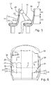
Figure 5 illustrates a side view of two adjacent rows of seats in the transverse layout; -
Figure 6 is a cross-section of the rail vehicle body through line VI-VI offigure 3 . - Corresponding reference numerals refer to the same or corresponding parts in each of the figures.
- A
vehicle body 10 of a rail vehicle according to an embodiment of the invention withseats 12 facing one end of the vehicle body, is illustrated infigure 1 . The same vehicle is illustrated infigure 2 with theseats 12 facing a transverse direction of the vehicle, and with a mixed layout is illustrated infigure 3 . - The
seats 12 used in the three configurations have a commonintegral base 14, illustrated infigure 4A , comprising aseat cushion 16 and abackrest 18. When used in the longitudinal layout offigure 2 , acovering strip 20 is added at theupper edge 22 of thebackrest 18 as illustrated infigures 4B and 4C . Thecovering strip 20 is provided withstems 24 that are inserted in corresponding tubular cavities formed in the backrest and opened at theupper edge 22. In the transverse configuration offigure 1 , on the other hand, thecovering strip 20 is removed and aheadrest 26 withstems 28 is fixed to thebackrest 18, as illustrated infigures 4D and 4E . In each configuration,specific support brackets headrest 26 is greater than two third of a distance D2 between theseat cushion 14 and theupper edge 22 of thebackrest 18, and preferably greater than the distance between the lower edge and the upper edge of the backrest. - As illustrated in
figure 5 , theseats 12 facing the longitudinal direction are arranged in rows such that thebackrests 18 of the seats of a first row are below a head impact point I of astandard dummy 34 sitting in a seat of a second row directly behind the first row. The lowupper edge 22 of thebackrest 18 makes it possible to obtain this result whilst maintaining a standard distance between the two adjacent rows ofseats 12. The stiffness of theheadrests 26 can be adapted to absorb the impact energy and minimise the risk of injury to meet predetermined crashworthiness requirements. - As illustrated in
figure 6 , theupper edge 22 of theseat backrest 18 in the longitudinal direction is located below a horizontal plane P defined by thewindow sills 36 of thevehicle body 10. Hence, no dust trap is formed between theseat backrest 18 and thewindow sill 36. Theseat backrest 18 does not impair the view through thewindow 38. - If necessary, the
support brackets seats 12 facing the longitudinal direction (figure 1 ) are higher than the seat cushions 14 of theseats 12 facing the transverse direction (figure 2 ). - According to an alternative embodiment, the same support brackets are used to fix the
seats 12 to the vehicle body structure, preferably to the side walls of the vehicle body structure, regardless of orientation.
Claims (14)
- A method of changing a seat configuration of a vehicle body (10) of a rail vehicle, the vehicle body (10) being provided with at least one set of seats (12) having seat cushions (16) and backrests (16) facing a first direction, the first direction being parallel or perpendicular to a longitudinal horizontal axis of the vehicle body (10), characterised in that it comprises:- disassembling the seats (12) from a vehicle body (10);- reassembling the seats (12) to the vehicle body to face a second direction perpendicular to the first direction; and- mounting headrests (26) to or dismounting headrests (26) from the seats (12), such that the seats (12) facing the longitudinal direction are provided with the headrests (26) and the seats (12) facing the transverse direction are without the headrests.
- The method of changing a seat configuration of claim 1, wherein the vehicle body (10) is provided with window sills (36) located in or above a horizontal reference plane (P) of the vehicle body (10), and the backrests (16) of the seats (12) facing the transverse direction are located below the horizontal reference plane (P).
- The method of changing a seat configuration of claim 1, wherein the seats (12) facing the longitudinal direction are arranged in rows such that the backrests (18) of the seats (12) of a first row are below a head impact point (I) of a standard dummy (34) sitting in a seat (12) of a second row directly behind the first row.
- The method of changing a seat configuration of any one of the preceding claims, wherein a distance (D1) between a lower edge to an upper edge of the headrests (26) is greater than two third of a distance (D2) between the seat cushion (16) and an upper edge (22) of the backrests (18), and preferably greater than the distance (D2) between the seat cushion (16) and an upper edge (22) of the backrests (18).
- The method of changing a seat configuration of any one of claims 1 to 4, wherein the vehicle body (10) is provided with support brackets (30) fixed to the vehicle body (10) for supporting the seats (12) facing the first direction, and wherein disassembling the seats (12) from the vehicle body (10) includes disassembling the seats (12) from the support brackets (30) fixed to the vehicle body (10), and reassembling the seats (12) to the vehicle body (10) to face a second direction includes reassembling the seats (12) to the support brackets (30) fixed to the vehicle body (10).
- The method of changing a seat configuration of any one of claims 1 to 4, wherein the vehicle body is provided with first support brackets (30) fixed to the vehicle body (10) for supporting the seats (12) facing the first direction, and second support brackets (32) fixed to the vehicle body (10) for supporting the seats (12) facing the second direction.
- The method of changing a seat configuration of any one of the preceding claims, wherein the seat cushions (16) of the seats (12) facing the longitudinal direction are higher than the seat cushions (16) of the seats (12) facing the transverse direction.
- A modular arrangement comprising a vehicle body (10) of a rail vehicle, at least one set of seats (12) having seat cushions (16) and backrests (18), a set of headrests (26), means (28) for reversibly mounting the headrests (26) to the seats (12), and assembling means (30, 32) for assembling the set of seats (12) to the vehicle body (10) so that the seats (12) face a longitudinal direction of the vehicle body and for assembling the set of seats (12) to the vehicle body (10) so that the seats (12) face a transverse direction of the vehicle body (10).
- The modular arrangement of claim 8, wherein the vehicle body (10) is provided with window sills (36) located in or above a horizontal reference plane (P) of the vehicle body (10), and the assembling means (30, 32) are such that the backrests (18) of the seats (12) facing the transverse direction are located below the horizontal reference plane (P).
- The modular arrangement of any one of claims 8 to 9, wherein the assembling means (30, 32) are such that the seats (12) facing the longitudinal direction are arranged in rows and the backrests (18) of the seats (12) of a first row are below a head impact point (I) of the seats (12) of a second row directly behind the first row.
- The modular arrangement of any one of claims 8 to 10, wherein a distance (D1) between a lower edge to an upper edge of the headrests (26) is greater than two third of a distance (D2) between the seat cushions (16) and an upper edge (22) of the backrests (18), and preferably greater than the distance (D2) between the seat cushions (16) and an upper edge (22) of the backrests (18).
- The modular arrangement of any one of claims 8 to 11, wherein the assembling means include support brackets (30) fixed to the vehicle body (10) for supporting both the seats (12) facing the first direction, and the seats (12) facing the second direction.
- The modular arrangement of any one of claims 8 to 11, wherein the assembling means include first support brackets (30) for supporting the seats (12) facing the first direction, and second support brackets (32) for supporting the seats (12) facing the second direction.
- The modular arrangement of any one of claims 8 to 11, wherein the assembling means (30, 32) are such that the seat cushions (16) of the seats (12) facing the longitudinal direction are higher than the seat cushions (16) of the seats (12) facing the transverse direction.
Priority Applications (1)
| Application Number | Priority Date | Filing Date | Title |
|---|---|---|---|
| EP16187870.7A EP3293040B1 (en) | 2016-09-08 | 2016-09-08 | Method of changing a seat configuration of a vehicle body of a rail vehicle and associated modular arrangement |
Applications Claiming Priority (1)
| Application Number | Priority Date | Filing Date | Title |
|---|---|---|---|
| EP16187870.7A EP3293040B1 (en) | 2016-09-08 | 2016-09-08 | Method of changing a seat configuration of a vehicle body of a rail vehicle and associated modular arrangement |
Publications (2)
| Publication Number | Publication Date |
|---|---|
| EP3293040A1 true EP3293040A1 (en) | 2018-03-14 |
| EP3293040B1 EP3293040B1 (en) | 2020-06-17 |
Family
ID=56889018
Family Applications (1)
| Application Number | Title | Priority Date | Filing Date |
|---|---|---|---|
| EP16187870.7A Active EP3293040B1 (en) | 2016-09-08 | 2016-09-08 | Method of changing a seat configuration of a vehicle body of a rail vehicle and associated modular arrangement |
Country Status (1)
| Country | Link |
|---|---|
| EP (1) | EP3293040B1 (en) |
Citations (2)
| Publication number | Priority date | Publication date | Assignee | Title |
|---|---|---|---|---|
| US20110140499A1 (en) * | 2009-12-14 | 2011-06-16 | James Masters | Modular transit system |
| US9308998B1 (en) * | 2015-01-05 | 2016-04-12 | Ami Industries, Inc. | Removable aircraft headrest |
-
2016
- 2016-09-08 EP EP16187870.7A patent/EP3293040B1/en active Active
Patent Citations (2)
| Publication number | Priority date | Publication date | Assignee | Title |
|---|---|---|---|---|
| US20110140499A1 (en) * | 2009-12-14 | 2011-06-16 | James Masters | Modular transit system |
| US9308998B1 (en) * | 2015-01-05 | 2016-04-12 | Ami Industries, Inc. | Removable aircraft headrest |
Also Published As
| Publication number | Publication date |
|---|---|
| EP3293040B1 (en) | 2020-06-17 |
Similar Documents
| Publication | Publication Date | Title |
|---|---|---|
| CN101407184B (en) | Seat arrangement for a motor vehicle and motor vehicle with such a seat arrangement | |
| US8317259B2 (en) | Seat device for vehicle | |
| US9102243B2 (en) | Seating arrangement for a passenger vehicle | |
| CN111469935A (en) | Rear body structure of vehicle | |
| EP2981459B1 (en) | Sidewall integrated armrest for aircraft interiors | |
| US20090134686A1 (en) | Vehicle seat | |
| US20120049604A1 (en) | Vehicle seat assembly | |
| JP2004131044A (en) | Front seat assembly for automobile | |
| US10569688B2 (en) | Seating module having a recessed grip and a seating arrangement including a seating module having a recessed grip | |
| US10500996B2 (en) | Vehicle seat | |
| CN118804852A (en) | Two-piece robot leg assembly for passenger seat | |
| EP3293040B1 (en) | Method of changing a seat configuration of a vehicle body of a rail vehicle and associated modular arrangement | |
| US20130234464A1 (en) | Seat attachment device in a motor vehicle and method for installing a second row of seats | |
| CN110576772B (en) | Vehicle interior structure | |
| JP5877184B2 (en) | Vehicle seat | |
| JP2022054147A (en) | On-vehicle seat | |
| JP2008284901A (en) | Car interior structure | |
| JP4349116B2 (en) | Vehicle fuel tank arrangement structure | |
| US7469970B2 (en) | Reinforcing structure for three-point type seat belt | |
| JP3114358U (en) | Seat arrangement in 3 or 4 car | |
| US7954872B2 (en) | Nesting seats for improved ingress/egress | |
| US11603024B2 (en) | Seating module having a recessed grip and a seating arrangement including a seating module having a recessed grip | |
| JPWO2016042631A1 (en) | Vehicle seat and method for manufacturing frame structure of vehicle seat | |
| US11390201B2 (en) | Seat assembly | |
| JP2008105575A (en) | Rear body structure of the vehicle |
Legal Events
| Date | Code | Title | Description |
|---|---|---|---|
| PUAI | Public reference made under article 153(3) epc to a published international application that has entered the european phase |
Free format text: ORIGINAL CODE: 0009012 |
|
| STAA | Information on the status of an ep patent application or granted ep patent |
Free format text: STATUS: THE APPLICATION HAS BEEN PUBLISHED |
|
| AK | Designated contracting states |
Kind code of ref document: A1 Designated state(s): AL AT BE BG CH CY CZ DE DK EE ES FI FR GB GR HR HU IE IS IT LI LT LU LV MC MK MT NL NO PL PT RO RS SE SI SK SM TR |
|
| AX | Request for extension of the european patent |
Extension state: BA ME |
|
| STAA | Information on the status of an ep patent application or granted ep patent |
Free format text: STATUS: REQUEST FOR EXAMINATION WAS MADE |
|
| 17P | Request for examination filed |
Effective date: 20180914 |
|
| RBV | Designated contracting states (corrected) |
Designated state(s): AL AT BE BG CH CY CZ DE DK EE ES FI FR GB GR HR HU IE IS IT LI LT LU LV MC MK MT NL NO PL PT RO RS SE SI SK SM TR |
|
| RIC1 | Information provided on ipc code assigned before grant |
Ipc: B61D 33/00 20060101ALI20170308BHEP Ipc: B60N 2/48 20181130ALI20170308BHEP Ipc: B60N 2/015 20060101ALI20170308BHEP Ipc: B60N 2/24 20060101ALI20170308BHEP Ipc: B60N 2/01 20060101AFI20170308BHEP |
|
| RIC1 | Information provided on ipc code assigned before grant |
Ipc: B60N 2/48 20060101ALI20170308BHEP Ipc: B60N 2/01 20060101AFI20170308BHEP Ipc: B60N 2/24 20060101ALI20170308BHEP Ipc: B61D 33/00 20060101ALI20170308BHEP Ipc: B60N 2/015 20060101ALI20170308BHEP |
|
| GRAP | Despatch of communication of intention to grant a patent |
Free format text: ORIGINAL CODE: EPIDOSNIGR1 |
|
| STAA | Information on the status of an ep patent application or granted ep patent |
Free format text: STATUS: GRANT OF PATENT IS INTENDED |
|
| RIC1 | Information provided on ipc code assigned before grant |
Ipc: B61D 33/00 20060101ALI20190910BHEP Ipc: B60N 2/24 20060101ALI20190910BHEP Ipc: B60N 2/01 20060101AFI20190910BHEP Ipc: B60N 2/015 20060101ALI20190910BHEP Ipc: B61D 1/04 20060101ALI20190910BHEP Ipc: B60N 2/882 20180101ALI20190910BHEP |
|
| INTG | Intention to grant announced |
Effective date: 20191016 |
|
| GRAS | Grant fee paid |
Free format text: ORIGINAL CODE: EPIDOSNIGR3 |
|
| GRAJ | Information related to disapproval of communication of intention to grant by the applicant or resumption of examination proceedings by the epo deleted |
Free format text: ORIGINAL CODE: EPIDOSDIGR1 |
|
| GRAL | Information related to payment of fee for publishing/printing deleted |
Free format text: ORIGINAL CODE: EPIDOSDIGR3 |
|
| STAA | Information on the status of an ep patent application or granted ep patent |
Free format text: STATUS: REQUEST FOR EXAMINATION WAS MADE |
|
| INTC | Intention to grant announced (deleted) | ||
| GRAR | Information related to intention to grant a patent recorded |
Free format text: ORIGINAL CODE: EPIDOSNIGR71 |
|
| STAA | Information on the status of an ep patent application or granted ep patent |
Free format text: STATUS: GRANT OF PATENT IS INTENDED |
|
| GRAA | (expected) grant |
Free format text: ORIGINAL CODE: 0009210 |
|
| STAA | Information on the status of an ep patent application or granted ep patent |
Free format text: STATUS: THE PATENT HAS BEEN GRANTED |
|
| AK | Designated contracting states |
Kind code of ref document: B1 Designated state(s): AL AT BE BG CH CY CZ DE DK EE ES FI FR GB GR HR HU IE IS IT LI LT LU LV MC MK MT NL NO PL PT RO RS SE SI SK SM TR |
|
| INTG | Intention to grant announced |
Effective date: 20200512 |
|
| REG | Reference to a national code |
Ref country code: GB Ref legal event code: FG4D |
|
| RIN1 | Information on inventor provided before grant (corrected) |
Inventor name: DAVIDSON, BRETT Inventor name: GRIGGS, PAUL |
|
| REG | Reference to a national code |
Ref country code: CH Ref legal event code: EP |
|
| REG | Reference to a national code |
Ref country code: IE Ref legal event code: FG4D |
|
| REG | Reference to a national code |
Ref country code: DE Ref legal event code: R096 Ref document number: 602016038116 Country of ref document: DE |
|
| REG | Reference to a national code |
Ref country code: AT Ref legal event code: REF Ref document number: 1280908 Country of ref document: AT Kind code of ref document: T Effective date: 20200715 |
|
| REG | Reference to a national code |
Ref country code: CH Ref legal event code: NV Representative=s name: TR-IP CONSULTING LLC, CH |
|
| REG | Reference to a national code |
Ref country code: SE Ref legal event code: TRGR |
|
| PG25 | Lapsed in a contracting state [announced via postgrant information from national office to epo] |
Ref country code: NO Free format text: LAPSE BECAUSE OF FAILURE TO SUBMIT A TRANSLATION OF THE DESCRIPTION OR TO PAY THE FEE WITHIN THE PRESCRIBED TIME-LIMIT Effective date: 20200917 Ref country code: FI Free format text: LAPSE BECAUSE OF FAILURE TO SUBMIT A TRANSLATION OF THE DESCRIPTION OR TO PAY THE FEE WITHIN THE PRESCRIBED TIME-LIMIT Effective date: 20200617 Ref country code: LT Free format text: LAPSE BECAUSE OF FAILURE TO SUBMIT A TRANSLATION OF THE DESCRIPTION OR TO PAY THE FEE WITHIN THE PRESCRIBED TIME-LIMIT Effective date: 20200617 Ref country code: GR Free format text: LAPSE BECAUSE OF FAILURE TO SUBMIT A TRANSLATION OF THE DESCRIPTION OR TO PAY THE FEE WITHIN THE PRESCRIBED TIME-LIMIT Effective date: 20200918 |
|
| REG | Reference to a national code |
Ref country code: LT Ref legal event code: MG4D |
|
| REG | Reference to a national code |
Ref country code: NL Ref legal event code: MP Effective date: 20200617 |
|
| PG25 | Lapsed in a contracting state [announced via postgrant information from national office to epo] |
Ref country code: BG Free format text: LAPSE BECAUSE OF FAILURE TO SUBMIT A TRANSLATION OF THE DESCRIPTION OR TO PAY THE FEE WITHIN THE PRESCRIBED TIME-LIMIT Effective date: 20200917 Ref country code: RS Free format text: LAPSE BECAUSE OF FAILURE TO SUBMIT A TRANSLATION OF THE DESCRIPTION OR TO PAY THE FEE WITHIN THE PRESCRIBED TIME-LIMIT Effective date: 20200617 Ref country code: LV Free format text: LAPSE BECAUSE OF FAILURE TO SUBMIT A TRANSLATION OF THE DESCRIPTION OR TO PAY THE FEE WITHIN THE PRESCRIBED TIME-LIMIT Effective date: 20200617 Ref country code: HR Free format text: LAPSE BECAUSE OF FAILURE TO SUBMIT A TRANSLATION OF THE DESCRIPTION OR TO PAY THE FEE WITHIN THE PRESCRIBED TIME-LIMIT Effective date: 20200617 |
|
| PG25 | Lapsed in a contracting state [announced via postgrant information from national office to epo] |
Ref country code: AL Free format text: LAPSE BECAUSE OF FAILURE TO SUBMIT A TRANSLATION OF THE DESCRIPTION OR TO PAY THE FEE WITHIN THE PRESCRIBED TIME-LIMIT Effective date: 20200617 Ref country code: NL Free format text: LAPSE BECAUSE OF FAILURE TO SUBMIT A TRANSLATION OF THE DESCRIPTION OR TO PAY THE FEE WITHIN THE PRESCRIBED TIME-LIMIT Effective date: 20200617 |
|
| PG25 | Lapsed in a contracting state [announced via postgrant information from national office to epo] |
Ref country code: ES Free format text: LAPSE BECAUSE OF FAILURE TO SUBMIT A TRANSLATION OF THE DESCRIPTION OR TO PAY THE FEE WITHIN THE PRESCRIBED TIME-LIMIT Effective date: 20200617 Ref country code: EE Free format text: LAPSE BECAUSE OF FAILURE TO SUBMIT A TRANSLATION OF THE DESCRIPTION OR TO PAY THE FEE WITHIN THE PRESCRIBED TIME-LIMIT Effective date: 20200617 Ref country code: SM Free format text: LAPSE BECAUSE OF FAILURE TO SUBMIT A TRANSLATION OF THE DESCRIPTION OR TO PAY THE FEE WITHIN THE PRESCRIBED TIME-LIMIT Effective date: 20200617 Ref country code: RO Free format text: LAPSE BECAUSE OF FAILURE TO SUBMIT A TRANSLATION OF THE DESCRIPTION OR TO PAY THE FEE WITHIN THE PRESCRIBED TIME-LIMIT Effective date: 20200617 Ref country code: IT Free format text: LAPSE BECAUSE OF FAILURE TO SUBMIT A TRANSLATION OF THE DESCRIPTION OR TO PAY THE FEE WITHIN THE PRESCRIBED TIME-LIMIT Effective date: 20200617 Ref country code: CZ Free format text: LAPSE BECAUSE OF FAILURE TO SUBMIT A TRANSLATION OF THE DESCRIPTION OR TO PAY THE FEE WITHIN THE PRESCRIBED TIME-LIMIT Effective date: 20200617 Ref country code: PT Free format text: LAPSE BECAUSE OF FAILURE TO SUBMIT A TRANSLATION OF THE DESCRIPTION OR TO PAY THE FEE WITHIN THE PRESCRIBED TIME-LIMIT Effective date: 20201019 |
|
| PG25 | Lapsed in a contracting state [announced via postgrant information from national office to epo] |
Ref country code: PL Free format text: LAPSE BECAUSE OF FAILURE TO SUBMIT A TRANSLATION OF THE DESCRIPTION OR TO PAY THE FEE WITHIN THE PRESCRIBED TIME-LIMIT Effective date: 20200617 Ref country code: SK Free format text: LAPSE BECAUSE OF FAILURE TO SUBMIT A TRANSLATION OF THE DESCRIPTION OR TO PAY THE FEE WITHIN THE PRESCRIBED TIME-LIMIT Effective date: 20200617 Ref country code: IS Free format text: LAPSE BECAUSE OF FAILURE TO SUBMIT A TRANSLATION OF THE DESCRIPTION OR TO PAY THE FEE WITHIN THE PRESCRIBED TIME-LIMIT Effective date: 20201017 |
|
| REG | Reference to a national code |
Ref country code: DE Ref legal event code: R097 Ref document number: 602016038116 Country of ref document: DE |
|
| PLBE | No opposition filed within time limit |
Free format text: ORIGINAL CODE: 0009261 |
|
| STAA | Information on the status of an ep patent application or granted ep patent |
Free format text: STATUS: NO OPPOSITION FILED WITHIN TIME LIMIT |
|
| PG25 | Lapsed in a contracting state [announced via postgrant information from national office to epo] |
Ref country code: DK Free format text: LAPSE BECAUSE OF FAILURE TO SUBMIT A TRANSLATION OF THE DESCRIPTION OR TO PAY THE FEE WITHIN THE PRESCRIBED TIME-LIMIT Effective date: 20200617 |
|
| 26N | No opposition filed |
Effective date: 20210318 |
|
| GBPC | Gb: european patent ceased through non-payment of renewal fee |
Effective date: 20200917 |
|
| PG25 | Lapsed in a contracting state [announced via postgrant information from national office to epo] |
Ref country code: SI Free format text: LAPSE BECAUSE OF FAILURE TO SUBMIT A TRANSLATION OF THE DESCRIPTION OR TO PAY THE FEE WITHIN THE PRESCRIBED TIME-LIMIT Effective date: 20200617 |
|
| REG | Reference to a national code |
Ref country code: BE Ref legal event code: MM Effective date: 20200930 |
|
| PG25 | Lapsed in a contracting state [announced via postgrant information from national office to epo] |
Ref country code: LU Free format text: LAPSE BECAUSE OF NON-PAYMENT OF DUE FEES Effective date: 20200908 |
|
| PG25 | Lapsed in a contracting state [announced via postgrant information from national office to epo] |
Ref country code: BE Free format text: LAPSE BECAUSE OF NON-PAYMENT OF DUE FEES Effective date: 20200930 Ref country code: GB Free format text: LAPSE BECAUSE OF NON-PAYMENT OF DUE FEES Effective date: 20200917 Ref country code: IE Free format text: LAPSE BECAUSE OF NON-PAYMENT OF DUE FEES Effective date: 20200908 |
|
| REG | Reference to a national code |
Ref country code: AT Ref legal event code: UEP Ref document number: 1280908 Country of ref document: AT Kind code of ref document: T Effective date: 20200617 |
|
| PG25 | Lapsed in a contracting state [announced via postgrant information from national office to epo] |
Ref country code: TR Free format text: LAPSE BECAUSE OF FAILURE TO SUBMIT A TRANSLATION OF THE DESCRIPTION OR TO PAY THE FEE WITHIN THE PRESCRIBED TIME-LIMIT Effective date: 20200617 Ref country code: MT Free format text: LAPSE BECAUSE OF FAILURE TO SUBMIT A TRANSLATION OF THE DESCRIPTION OR TO PAY THE FEE WITHIN THE PRESCRIBED TIME-LIMIT Effective date: 20200617 Ref country code: CY Free format text: LAPSE BECAUSE OF FAILURE TO SUBMIT A TRANSLATION OF THE DESCRIPTION OR TO PAY THE FEE WITHIN THE PRESCRIBED TIME-LIMIT Effective date: 20200617 |
|
| PG25 | Lapsed in a contracting state [announced via postgrant information from national office to epo] |
Ref country code: MK Free format text: LAPSE BECAUSE OF FAILURE TO SUBMIT A TRANSLATION OF THE DESCRIPTION OR TO PAY THE FEE WITHIN THE PRESCRIBED TIME-LIMIT Effective date: 20200617 Ref country code: MC Free format text: LAPSE BECAUSE OF FAILURE TO SUBMIT A TRANSLATION OF THE DESCRIPTION OR TO PAY THE FEE WITHIN THE PRESCRIBED TIME-LIMIT Effective date: 20200617 |
|
| P01 | Opt-out of the competence of the unified patent court (upc) registered |
Effective date: 20230822 |
|
| REG | Reference to a national code |
Ref country code: CH Ref legal event code: U11 Free format text: ST27 STATUS EVENT CODE: U-0-0-U10-U11 (AS PROVIDED BY THE NATIONAL OFFICE) Effective date: 20251001 |
|
| PGFP | Annual fee paid to national office [announced via postgrant information from national office to epo] |
Ref country code: DE Payment date: 20250919 Year of fee payment: 10 |
|
| PGFP | Annual fee paid to national office [announced via postgrant information from national office to epo] |
Ref country code: FR Payment date: 20250922 Year of fee payment: 10 Ref country code: AT Payment date: 20250919 Year of fee payment: 10 |
|
| PGFP | Annual fee paid to national office [announced via postgrant information from national office to epo] |
Ref country code: SE Payment date: 20250918 Year of fee payment: 10 |
|
| PGFP | Annual fee paid to national office [announced via postgrant information from national office to epo] |
Ref country code: CH Payment date: 20251001 Year of fee payment: 10 |