EP3293000B1 - Method of manufacturing a multilayer composite with intumescent material and engine component - Google Patents
Method of manufacturing a multilayer composite with intumescent material and engine component Download PDFInfo
- Publication number
- EP3293000B1 EP3293000B1 EP17187735.0A EP17187735A EP3293000B1 EP 3293000 B1 EP3293000 B1 EP 3293000B1 EP 17187735 A EP17187735 A EP 17187735A EP 3293000 B1 EP3293000 B1 EP 3293000B1
- Authority
- EP
- European Patent Office
- Prior art keywords
- layer
- intumescent
- resin
- poriferous
- engine
- Prior art date
- Legal status (The legal status is an assumption and is not a legal conclusion. Google has not performed a legal analysis and makes no representation as to the accuracy of the status listed.)
- Active
Links
- 239000000463 material Substances 0.000 title claims description 182
- 238000004519 manufacturing process Methods 0.000 title claims description 23
- 239000002131 composite material Substances 0.000 title description 76
- 229920005989 resin Polymers 0.000 claims description 83
- 239000011347 resin Substances 0.000 claims description 83
- 238000010438 heat treatment Methods 0.000 claims description 18
- 238000000034 method Methods 0.000 claims description 18
- 238000005470 impregnation Methods 0.000 claims description 9
- 239000007788 liquid Substances 0.000 claims description 7
- 239000012530 fluid Substances 0.000 claims description 4
- 239000007767 bonding agent Substances 0.000 claims 3
- 238000005253 cladding Methods 0.000 claims 1
- 239000010410 layer Substances 0.000 description 192
- 239000011148 porous material Substances 0.000 description 24
- 230000006835 compression Effects 0.000 description 13
- 238000007906 compression Methods 0.000 description 13
- 239000012790 adhesive layer Substances 0.000 description 9
- 239000003063 flame retardant Substances 0.000 description 9
- 241000264877 Hippospongia communis Species 0.000 description 8
- 238000007789 sealing Methods 0.000 description 5
- 239000007789 gas Substances 0.000 description 4
- 230000000630 rising effect Effects 0.000 description 4
- 239000000243 solution Substances 0.000 description 4
- 230000004888 barrier function Effects 0.000 description 3
- 238000002485 combustion reaction Methods 0.000 description 3
- 238000010586 diagram Methods 0.000 description 3
- 239000000835 fiber Substances 0.000 description 3
- 239000006260 foam Substances 0.000 description 3
- 238000002347 injection Methods 0.000 description 3
- 239000007924 injection Substances 0.000 description 3
- 239000004745 nonwoven fabric Substances 0.000 description 3
- 238000010943 off-gassing Methods 0.000 description 3
- 239000011342 resin composition Substances 0.000 description 3
- 229920002430 Fibre-reinforced plastic Polymers 0.000 description 2
- 230000004913 activation Effects 0.000 description 2
- 238000002156 mixing Methods 0.000 description 2
- 239000000047 product Substances 0.000 description 2
- 238000009745 resin transfer moulding Methods 0.000 description 2
- 230000000087 stabilizing effect Effects 0.000 description 2
- 229920001187 thermosetting polymer Polymers 0.000 description 2
- 241001295925 Gegenes Species 0.000 description 1
- -1 Tecnofire® Substances 0.000 description 1
- 239000000853 adhesive Substances 0.000 description 1
- 230000001070 adhesive effect Effects 0.000 description 1
- QVGXLLKOCUKJST-UHFFFAOYSA-N atomic oxygen Chemical compound [O] QVGXLLKOCUKJST-UHFFFAOYSA-N 0.000 description 1
- 230000015572 biosynthetic process Effects 0.000 description 1
- 239000004566 building material Substances 0.000 description 1
- 238000010276 construction Methods 0.000 description 1
- 238000013016 damping Methods 0.000 description 1
- 230000000694 effects Effects 0.000 description 1
- 239000003733 fiber-reinforced composite Substances 0.000 description 1
- 238000005187 foaming Methods 0.000 description 1
- 238000009434 installation Methods 0.000 description 1
- 238000009413 insulation Methods 0.000 description 1
- 239000011159 matrix material Substances 0.000 description 1
- 239000000203 mixture Substances 0.000 description 1
- 239000001301 oxygen Substances 0.000 description 1
- 229910052760 oxygen Inorganic materials 0.000 description 1
- 238000004321 preservation Methods 0.000 description 1
- 238000003825 pressing Methods 0.000 description 1
- 230000002787 reinforcement Effects 0.000 description 1
- 239000011265 semifinished product Substances 0.000 description 1
- 238000010583 slow cooling Methods 0.000 description 1
- 230000006641 stabilisation Effects 0.000 description 1
- 238000011105 stabilization Methods 0.000 description 1
- 230000008961 swelling Effects 0.000 description 1
- 239000004753 textile Substances 0.000 description 1
- 239000010409 thin film Substances 0.000 description 1
- 238000001721 transfer moulding Methods 0.000 description 1
- 230000001960 triggered effect Effects 0.000 description 1
- 238000009834 vaporization Methods 0.000 description 1
- 230000008016 vaporization Effects 0.000 description 1
Images


Classifications
-
- B—PERFORMING OPERATIONS; TRANSPORTING
- B32—LAYERED PRODUCTS
- B32B—LAYERED PRODUCTS, i.e. PRODUCTS BUILT-UP OF STRATA OF FLAT OR NON-FLAT, e.g. CELLULAR OR HONEYCOMB, FORM
- B32B37/00—Methods or apparatus for laminating, e.g. by curing or by ultrasonic bonding
- B32B37/14—Methods or apparatus for laminating, e.g. by curing or by ultrasonic bonding characterised by the properties of the layers
- B32B37/144—Methods or apparatus for laminating, e.g. by curing or by ultrasonic bonding characterised by the properties of the layers using layers with different mechanical or chemical conditions or properties, e.g. layers with different thermal shrinkage, layers under tension during bonding
-
- B—PERFORMING OPERATIONS; TRANSPORTING
- B29—WORKING OF PLASTICS; WORKING OF SUBSTANCES IN A PLASTIC STATE IN GENERAL
- B29C—SHAPING OR JOINING OF PLASTICS; SHAPING OF MATERIAL IN A PLASTIC STATE, NOT OTHERWISE PROVIDED FOR; AFTER-TREATMENT OF THE SHAPED PRODUCTS, e.g. REPAIRING
- B29C70/00—Shaping composites, i.e. plastics material comprising reinforcements, fillers or preformed parts, e.g. inserts
- B29C70/04—Shaping composites, i.e. plastics material comprising reinforcements, fillers or preformed parts, e.g. inserts comprising reinforcements only, e.g. self-reinforcing plastics
- B29C70/28—Shaping operations therefor
- B29C70/40—Shaping or impregnating by compression not applied
- B29C70/42—Shaping or impregnating by compression not applied for producing articles of definite length, i.e. discrete articles
- B29C70/44—Shaping or impregnating by compression not applied for producing articles of definite length, i.e. discrete articles using isostatic pressure, e.g. pressure difference-moulding, vacuum bag-moulding, autoclave-moulding or expanding rubber-moulding
- B29C70/443—Shaping or impregnating by compression not applied for producing articles of definite length, i.e. discrete articles using isostatic pressure, e.g. pressure difference-moulding, vacuum bag-moulding, autoclave-moulding or expanding rubber-moulding and impregnating by vacuum or injection
-
- B—PERFORMING OPERATIONS; TRANSPORTING
- B29—WORKING OF PLASTICS; WORKING OF SUBSTANCES IN A PLASTIC STATE IN GENERAL
- B29C—SHAPING OR JOINING OF PLASTICS; SHAPING OF MATERIAL IN A PLASTIC STATE, NOT OTHERWISE PROVIDED FOR; AFTER-TREATMENT OF THE SHAPED PRODUCTS, e.g. REPAIRING
- B29C70/00—Shaping composites, i.e. plastics material comprising reinforcements, fillers or preformed parts, e.g. inserts
- B29C70/04—Shaping composites, i.e. plastics material comprising reinforcements, fillers or preformed parts, e.g. inserts comprising reinforcements only, e.g. self-reinforcing plastics
- B29C70/28—Shaping operations therefor
- B29C70/40—Shaping or impregnating by compression not applied
- B29C70/42—Shaping or impregnating by compression not applied for producing articles of definite length, i.e. discrete articles
- B29C70/46—Shaping or impregnating by compression not applied for producing articles of definite length, i.e. discrete articles using matched moulds, e.g. for deforming sheet moulding compounds [SMC] or prepregs
- B29C70/48—Shaping or impregnating by compression not applied for producing articles of definite length, i.e. discrete articles using matched moulds, e.g. for deforming sheet moulding compounds [SMC] or prepregs and impregnating the reinforcements in the closed mould, e.g. resin transfer moulding [RTM], e.g. by vacuum
-
- B—PERFORMING OPERATIONS; TRANSPORTING
- B32—LAYERED PRODUCTS
- B32B—LAYERED PRODUCTS, i.e. PRODUCTS BUILT-UP OF STRATA OF FLAT OR NON-FLAT, e.g. CELLULAR OR HONEYCOMB, FORM
- B32B3/00—Layered products comprising a layer with external or internal discontinuities or unevennesses, or a layer of non-planar form; Layered products having particular features of form
- B32B3/10—Layered products comprising a layer with external or internal discontinuities or unevennesses, or a layer of non-planar form; Layered products having particular features of form characterised by a discontinuous layer, i.e. formed of separate pieces of material
- B32B3/12—Layered products comprising a layer with external or internal discontinuities or unevennesses, or a layer of non-planar form; Layered products having particular features of form characterised by a discontinuous layer, i.e. formed of separate pieces of material characterised by a layer of regularly- arranged cells, e.g. a honeycomb structure
-
- B—PERFORMING OPERATIONS; TRANSPORTING
- B32—LAYERED PRODUCTS
- B32B—LAYERED PRODUCTS, i.e. PRODUCTS BUILT-UP OF STRATA OF FLAT OR NON-FLAT, e.g. CELLULAR OR HONEYCOMB, FORM
- B32B5/00—Layered products characterised by the non- homogeneity or physical structure, i.e. comprising a fibrous, filamentary, particulate or foam layer; Layered products characterised by having a layer differing constitutionally or physically in different parts
- B32B5/02—Layered products characterised by the non- homogeneity or physical structure, i.e. comprising a fibrous, filamentary, particulate or foam layer; Layered products characterised by having a layer differing constitutionally or physically in different parts characterised by structural features of a fibrous or filamentary layer
- B32B5/022—Non-woven fabric
-
- B—PERFORMING OPERATIONS; TRANSPORTING
- B32—LAYERED PRODUCTS
- B32B—LAYERED PRODUCTS, i.e. PRODUCTS BUILT-UP OF STRATA OF FLAT OR NON-FLAT, e.g. CELLULAR OR HONEYCOMB, FORM
- B32B5/00—Layered products characterised by the non- homogeneity or physical structure, i.e. comprising a fibrous, filamentary, particulate or foam layer; Layered products characterised by having a layer differing constitutionally or physically in different parts
- B32B5/18—Layered products characterised by the non- homogeneity or physical structure, i.e. comprising a fibrous, filamentary, particulate or foam layer; Layered products characterised by having a layer differing constitutionally or physically in different parts characterised by features of a layer of foamed material
-
- B—PERFORMING OPERATIONS; TRANSPORTING
- B32—LAYERED PRODUCTS
- B32B—LAYERED PRODUCTS, i.e. PRODUCTS BUILT-UP OF STRATA OF FLAT OR NON-FLAT, e.g. CELLULAR OR HONEYCOMB, FORM
- B32B5/00—Layered products characterised by the non- homogeneity or physical structure, i.e. comprising a fibrous, filamentary, particulate or foam layer; Layered products characterised by having a layer differing constitutionally or physically in different parts
- B32B5/22—Layered products characterised by the non- homogeneity or physical structure, i.e. comprising a fibrous, filamentary, particulate or foam layer; Layered products characterised by having a layer differing constitutionally or physically in different parts characterised by the presence of two or more layers which are next to each other and are fibrous, filamentary, formed of particles or foamed
- B32B5/24—Layered products characterised by the non- homogeneity or physical structure, i.e. comprising a fibrous, filamentary, particulate or foam layer; Layered products characterised by having a layer differing constitutionally or physically in different parts characterised by the presence of two or more layers which are next to each other and are fibrous, filamentary, formed of particles or foamed one layer being a fibrous or filamentary layer
- B32B5/26—Layered products characterised by the non- homogeneity or physical structure, i.e. comprising a fibrous, filamentary, particulate or foam layer; Layered products characterised by having a layer differing constitutionally or physically in different parts characterised by the presence of two or more layers which are next to each other and are fibrous, filamentary, formed of particles or foamed one layer being a fibrous or filamentary layer another layer next to it also being fibrous or filamentary
-
- B—PERFORMING OPERATIONS; TRANSPORTING
- B32—LAYERED PRODUCTS
- B32B—LAYERED PRODUCTS, i.e. PRODUCTS BUILT-UP OF STRATA OF FLAT OR NON-FLAT, e.g. CELLULAR OR HONEYCOMB, FORM
- B32B7/00—Layered products characterised by the relation between layers; Layered products characterised by the relative orientation of features between layers, or by the relative values of a measurable parameter between layers, i.e. products comprising layers having different physical, chemical or physicochemical properties; Layered products characterised by the interconnection of layers
- B32B7/04—Interconnection of layers
- B32B7/12—Interconnection of layers using interposed adhesives or interposed materials with bonding properties
-
- B—PERFORMING OPERATIONS; TRANSPORTING
- B32—LAYERED PRODUCTS
- B32B—LAYERED PRODUCTS, i.e. PRODUCTS BUILT-UP OF STRATA OF FLAT OR NON-FLAT, e.g. CELLULAR OR HONEYCOMB, FORM
- B32B2260/00—Layered product comprising an impregnated, embedded, or bonded layer wherein the layer comprises an impregnation, embedding, or binder material
- B32B2260/02—Composition of the impregnated, bonded or embedded layer
- B32B2260/021—Fibrous or filamentary layer
-
- B—PERFORMING OPERATIONS; TRANSPORTING
- B32—LAYERED PRODUCTS
- B32B—LAYERED PRODUCTS, i.e. PRODUCTS BUILT-UP OF STRATA OF FLAT OR NON-FLAT, e.g. CELLULAR OR HONEYCOMB, FORM
- B32B2260/00—Layered product comprising an impregnated, embedded, or bonded layer wherein the layer comprises an impregnation, embedding, or binder material
- B32B2260/04—Impregnation, embedding, or binder material
- B32B2260/046—Synthetic resin
-
- B—PERFORMING OPERATIONS; TRANSPORTING
- B32—LAYERED PRODUCTS
- B32B—LAYERED PRODUCTS, i.e. PRODUCTS BUILT-UP OF STRATA OF FLAT OR NON-FLAT, e.g. CELLULAR OR HONEYCOMB, FORM
- B32B2262/00—Composition or structural features of fibres which form a fibrous or filamentary layer or are present as additives
- B32B2262/10—Inorganic fibres
- B32B2262/106—Carbon fibres, e.g. graphite fibres
-
- B—PERFORMING OPERATIONS; TRANSPORTING
- B32—LAYERED PRODUCTS
- B32B—LAYERED PRODUCTS, i.e. PRODUCTS BUILT-UP OF STRATA OF FLAT OR NON-FLAT, e.g. CELLULAR OR HONEYCOMB, FORM
- B32B2307/00—Properties of the layers or laminate
- B32B2307/30—Properties of the layers or laminate having particular thermal properties
- B32B2307/306—Resistant to heat
- B32B2307/3065—Flame resistant or retardant, fire resistant or retardant
-
- B—PERFORMING OPERATIONS; TRANSPORTING
- B32—LAYERED PRODUCTS
- B32B—LAYERED PRODUCTS, i.e. PRODUCTS BUILT-UP OF STRATA OF FLAT OR NON-FLAT, e.g. CELLULAR OR HONEYCOMB, FORM
- B32B2307/00—Properties of the layers or laminate
- B32B2307/70—Other properties
- B32B2307/726—Permeability to liquids, absorption
- B32B2307/7265—Non-permeable
-
- B—PERFORMING OPERATIONS; TRANSPORTING
- B32—LAYERED PRODUCTS
- B32B—LAYERED PRODUCTS, i.e. PRODUCTS BUILT-UP OF STRATA OF FLAT OR NON-FLAT, e.g. CELLULAR OR HONEYCOMB, FORM
- B32B2605/00—Vehicles
- B32B2605/18—Aircraft
-
- B—PERFORMING OPERATIONS; TRANSPORTING
- B32—LAYERED PRODUCTS
- B32B—LAYERED PRODUCTS, i.e. PRODUCTS BUILT-UP OF STRATA OF FLAT OR NON-FLAT, e.g. CELLULAR OR HONEYCOMB, FORM
- B32B27/00—Layered products comprising a layer of synthetic resin
- B32B27/04—Layered products comprising a layer of synthetic resin as impregnant, bonding, or embedding substance
-
- B—PERFORMING OPERATIONS; TRANSPORTING
- B32—LAYERED PRODUCTS
- B32B—LAYERED PRODUCTS, i.e. PRODUCTS BUILT-UP OF STRATA OF FLAT OR NON-FLAT, e.g. CELLULAR OR HONEYCOMB, FORM
- B32B37/00—Methods or apparatus for laminating, e.g. by curing or by ultrasonic bonding
- B32B37/10—Methods or apparatus for laminating, e.g. by curing or by ultrasonic bonding characterised by the pressing technique, e.g. using action of vacuum or fluid pressure
-
- B—PERFORMING OPERATIONS; TRANSPORTING
- B32—LAYERED PRODUCTS
- B32B—LAYERED PRODUCTS, i.e. PRODUCTS BUILT-UP OF STRATA OF FLAT OR NON-FLAT, e.g. CELLULAR OR HONEYCOMB, FORM
- B32B37/00—Methods or apparatus for laminating, e.g. by curing or by ultrasonic bonding
- B32B37/14—Methods or apparatus for laminating, e.g. by curing or by ultrasonic bonding characterised by the properties of the layers
- B32B37/26—Methods or apparatus for laminating, e.g. by curing or by ultrasonic bonding characterised by the properties of the layers with at least one layer which influences the bonding during the lamination process, e.g. release layers or pressure equalising layers
-
- F—MECHANICAL ENGINEERING; LIGHTING; HEATING; WEAPONS; BLASTING
- F05—INDEXING SCHEMES RELATING TO ENGINES OR PUMPS IN VARIOUS SUBCLASSES OF CLASSES F01-F04
- F05D—INDEXING SCHEME FOR ASPECTS RELATING TO NON-POSITIVE-DISPLACEMENT MACHINES OR ENGINES, GAS-TURBINES OR JET-PROPULSION PLANTS
- F05D2300/00—Materials; Properties thereof
- F05D2300/60—Properties or characteristics given to material by treatment or manufacturing
- F05D2300/603—Composites; e.g. fibre-reinforced
Definitions
- the invention relates to a method for producing a composite layer for an engine component and an engine component.
- a layer composite from which an engine component is made consists of at least two layers of different material, which are connected to one another in a material and / or form-fitting manner.
- engine components it is also known to provide these multilayer laminates with at least one fire-retardant or refractory layer to achieve a predetermined fire resistance or fire resistance.
- a foreclosed area can then be defined in order to prevent or at least limit fire propagation within the engine.
- intumescent, porous building materials that swell or foam under heat and thus increase their volume considerably in case of fire.
- the intumescent material serves, for example, to form an incinerating insulation layer, through which the Oxygen supply and thus a spread of a flame is hindered.
- the expanding intumescent material can also be used to seal a critical area, so that a flame can not spread further in it.
- Laminated composites with at least one layer with an intumescent, porous material are, for example, from AU 2006-235991 A1 , of the EP 0 949 313 B1 . US 2005/136761 A1 or the US 2011/147358 A1 known.
- intumescent materials in the engine area is not common. Accordingly, at present there are at most some rudimentary considerations for making a layer composite having at least one layer with an intumescent material as compact and easy as possible, so that use in the engine sector is meaningfully possible.
- the invention is therefore based on the object to provide a composite layer for the creation of an engine component, which is improved in terms of requirements in the engine area.
- the invention is thus based on the basic idea of adopting the porous, possibly also porous, property of an intumescent material in order to achieve this impregnated in a compressed form with a resin or a resin composition and thus form a composite layer to be produced with an intumescent material having a reduced wall thickness.
- the supplied resin serves on the one hand to increase the rigidity and resistance of the layer with the intumescent, porous material in the laminate and to connect the layer with the intumescent material cohesively with the at least one further layer.
- the material layer of the intumescent material is preserved and sealed in its compressed form within the layer composite.
- an intumescent, porous material By using an intumescent, porous material, it is ensured that the introduced resin or the introduced resin composition can be absorbed by the porous or porous intumescent material and thus the intumescent material can be impregnated by the resin and - after it has hardened - sealed. A sealed layer, which is resistant to fluid effects, can then be formed on the engine component by means of the intumescent material sealed by the resin.
- the intumescent material has, for example, a porosity of more than 70%, in particular in the range of more than 85% or about 90%.
- the intumescent material for example, in the raw state felt like a felt before as a material layer of a nonwoven fabric. For example, a material layer made of Tecnofire® from Technical Fiber Products Ltd. used.
- the resin in the case of fire or at a temperature rising above a critical threshold, the resin is vaporized out of the intumescent material and releases the intumescent material so that it can swell or foam to act as a fire retardant or fire retardant.
- a first increase in volume of the layer with the intumescent material is already permitted by the outgassing resin, since the resin no longer holds this layer in its compressed form.
- a temperature-driven increase in volume of the intumescent material takes place.
- a controlled flaming can be achieved by the outgassing resin, burned in resin soaked material of the composite layer similar to a candle, before then by the (further) swelling or foaming of the intumescent material, a barrier is generated, which counteracts further flame propagation.
- the layer with the intumescent material works in case of fire or already at a temperature above a critical threshold rising temperature as a kind of heat shield.
- the at least one further layer or material layer for forming the layer composite is formed in one embodiment by a composite material.
- a material layer for the further layer in the form of a prepreg that is to say a preimpregnated textile fiber-matrix semifinished product, is provided in this case.
- a layer of another fiber-reinforced material may be provided.
- a heating of the stacked material layers to at least a minimum temperature is provided for the impregnation with the resin.
- the heating takes place in this case, for example, by heating a receiving space of the tool which receives the stacked layers of material.
- This receiving space is defined for example by a cavity in a shell mold or by an autoclave.
- the heating serves, for example, to hold liquid of the introduced resin or to cure the resin in a thermosetting resin.
- the introduction of the resin can be done for example by a separate resin layer, which is provided in the stacked layers of material.
- an injection of the resin for example by means of a Resin Transfer Molding ("RTM") or vacuum assisted by a VARI or VARTM method (short for English "Vaccum Assisted Resin Injection” or "Vacuum Assisted Resin Transfer )
- RTM Resin Transfer Molding
- VARI or VARTM method vacuum assisted by a VARI or VARTM method
- the resin contained therein may be liquefied by pressurization and heating in the course of making the laminate, and then used to impregnate the compressed intumescent material stacked thereon.
- a heating of the stacked layers of material to a minimum temperature of about 70 ° C is provided for the impregnation, in order to achieve that the resin or the resin composition sufficiently impregnated the compressed intumescent material.
- the further manufacturing process may provide that the temperature is subsequently increased stepwise up to a first maximum temperature of about 120 ° C and then up to a second maximum temperature of about 175 ° C.
- a defined residence time at a first maximum temperature e.g. in the amount of 120 ° C, serves to stress compensation during curing, since it is to be ensured that tools and layer composite have a balanced temperature before the actual hardening takes place by increasing to the second maximum temperature.
- the pressure for compressing at least the material layer of the intumescent, porous material is applied before the minimum temperature, of, for example, 70 ° C, is reached.
- the pressure can be applied if a heater for heating the stacked material layers is activated to the minimum temperature or before such a heater is activated.
- the intended (compression) pressure is applied at the time at which or shortly after the heater is activated and thus a heating process is triggered.
- the intended (compression) pressure for compressing at least the material layer of the intumescent material is in the range from 5 to 8 bar, in particular in the range from 5.5 to 7.5 bar.
- a pressure of about 7 bar is provided.
- the resin intended for impregnation can be used as a separate material layer in the stacked layer Be provided material layers.
- the resin is provided here, for example, as a comparatively thin layer between a material layer of the intumescent material and a further material layer made of a composite material. Upon subsequent heating and compression, the resin then penetrates and bonds the intumescent material and the composite.
- Such a method can be implemented, for example, in an autoclave.
- the at least one layer of material for the at least one further layer of the layer composite can be preimpregnated and thus the resin intended for impregnating the intumescent, porous material at least partially originate from the preimpregnated material layer.
- the above-described variant in which the (compression) pressure for compressing at least the material layer of the intumescent material is applied early before a heating of the material layers stacked on one another can prove to be particularly advantageous.
- At least one layer of adhesive may be provided in a variant embodiment.
- This adhesive layer may contain a - optionally additional - resin, which is at least partially used to impregnate the intumescent material.
- an autoclave is used as a tool, by means of which the pressure for compressing at least the material layer of the intumescent, porous material is applied to the stacked material layers.
- a manufacturing process provided here can then, for example, in particular provide an autoclave cycle in which the pressure intended for compressing the intumescent material is applied at an early stage before the stacked material layers are heated.
- the intumescent, porous material used is chosen, for example, and the pressure applied thereto is set so high that the layer with the intumescent, porous material in the layer composite produced does not exceed a thickness of 2.3 mm.
- a (layer) thickness is, for example, in the range of 0.4 mm to 1.5 mm.
- a further aspect of the solution according to the invention is the provision of a layer composite from which an engine component can be produced at least partially.
- Such a layer composite is in this case constructed in multiple layers and has at least one layer with an intumescent, porous material and at least one further layer, for example of a composite material.
- a material layer of intumescent, porous material is impregnated by a resin which, in its hardened state, holds the material layer of intumescent, porous material in the layer composite in a compressed form and against the ingress of a liquid also seals against ingress of moisture and gases.
- Such a layer composite can thus be produced by a production method according to the invention. Accordingly, advantages and features of embodiments of a manufacturing method according to the invention mentioned above and below also apply to variants of such a layer composite and vice versa.
- an engine component for a gas turbine engine is produced with such a layer composite.
- Such an engine component may, for example, an engine housing (also referred to as gondola or English "nacelle"), a fan housing, a wall of a bypass duct or a trim component for the enclosure of at least one line and / or electronic and / or fluid leading component and / or assembly to be inside the engine.
- an engine housing also referred to as gondola or English "nacelle”
- a fan housing for the enclosure of at least one line and / or electronic and / or fluid leading component and / or assembly to be inside the engine.
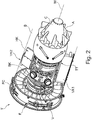
- FIG. 1 illustrates schematically and in section a (turbofan) engine T, in which the individual engine components along a rotation axis or central axis M are arranged one behind the other.
- a fan F At an inlet or intake E of the engine T, air is drawn in along an inlet direction R by means of a fan F.
- This arranged in a fan housing FC fan F is driven by a rotor shaft RS, which is rotated by a turbine TT of the engine T in rotation.
- the turbine TT is in this case connected to a compressor V, for example, a Low-pressure compressor 11 and a high-pressure compressor 12 has, and optionally also a medium-pressure compressor.
- the fan F supplies air to the compressor V and, on the other hand, a secondary flow channel or bypass channel B for generating the thrust.
- the bypass channel B in this case extends around a compressor V and the turbine TT comprehensive core engine, which includes a primary flow channel for the supplied through the fan F the core engine air.
- the bypass duct B is delimited by an engine casing N, which is usually referred to as a nacelle.
- the air conveyed into the primary flow passage via the compressor V enters a combustion chamber section BK of the core engine in which the driving power for driving the turbine TT is generated.
- the turbine TT has a high-pressure turbine 13, a medium-pressure turbine 14 and a low-pressure turbine 15.
- the turbine TT thereby drives the rotor shaft RS and thus the fan F via the energy released during combustion in order to generate the required thrust via the air conveyed into the bypass channel B.
- Both the air from the bypass passage B and the exhaust gases from the primary flow passage of the core engine flow through an outlet A at the end of the engine T.
- the outlet A in this case usually has a discharge nozzle with a centrally arranged outlet cone C.
- FIG. 1 Based on FIG. 1 is exemplified in the region of the engine housing N, a bypass channel B bounding wall and / or an outer circumferential surface of the engine housing N via a multi-layer composite layer 2a or 2b build.
- a wall bordering the bypass channel B may in this case be provided with a fire-retardant or refractory layer in order to avoid flame propagation in the event of a fire occurring in the engine T.
- parts of the housing are made of a layer composite and thus of a composite material, wherein such a layer composite usually has at least one layer of a refractory or at least fire retardant material.
- FIG. 2 Based on FIG. 2 in which the engine T the FIG. 1 in a perspective view with a greater degree of detail and without the engine housing N is shown, further engine components are exemplified, which can be made of a layer composite with at least one refractory or fire-retardant layer.
- a lining component VK2 forms for this purpose a trailing edge HK, which tapers in the flow direction of the fluid flowing in the bypass channel B during operation of the engine.
- the trim components VK1 and VK2 are commonly referred to in English as “fairings” or “splitter fairing”.
- linings or housings which are accommodated within a cavity in the engine housing N can also be produced from a layer composite which, for fire protection reasons, is provided with a refractory or fire-retardant material.
- the solution according to the invention proposes to produce a layer composite, such as layer composite 2a or 2b, with an intumescent, porous material and additionally by a process in which a material layer of the intumescent, porous material is impregnated in compressed form with a resin and held and sealed in its compressed form.
- At least one layer is thus provided in a layer composite, which preferably integrates a plurality of composite materials, which at a temperature rising above a threshold (eg of 195 ° C) and in particular in a fire within the engine T by a multiple of their original volume increases and thereby provides an insulating layer in the manner of a heat shield and / or targeted by their increase in volume areas closes, so that a flame can not easily spread into these areas.
- a threshold eg of 195 ° C
- a material layer 21 'of intumescent material in a tool 1 on a composite material layer 20', for example, with fiber reinforcement, is placed. Subsequently, by means of the tool 1, an increased pressure p for compression of the layered material layers 20 'and 21' applied. Here, in particular, the material layer of intumescent material 21 'is compressed.
- a resin from a resin supply 10 of the tool 1 for impregnating the compressed material layers 20 'and 21' is introduced.
- the preferably highly porous intumescent material of the material layer 21 ' is filled with the resin, so that not only the two layers of material 20' and 21 'are integrally bonded to each other via the resin, but also kept the material layer 21' of the intumescent material in its compressed form and sealed.
- the cured resin thus preserves the compressed shape of the intumescent material and seals it against the ingress of liquids to the outside.
- the introduction of the resin via the resin feed 10 takes place, for example, in the manner of a resin injection process (RTM process) or vacuum assisted in a VARI or VARTM process.
- Tecnofire® of Technical Fiber Products Ltd. can be used as an example. at.
- other intumescent materials are also suitable, in particular those which are felt-like and in the form of a flexible nonwoven fabric.
- a composite layer 2 in which several layers 20 and 21 are interconnected.
- a composite layer 20, commonly referred to as a composite laminate is provided for providing the desired structural properties such as stiffness and strength.
- the at least one additional layer 21 with the compressed intumescent material serves for fire protection.
- This layer 21 is comparatively thin-walled and has only a (layer) thickness of less than 2 mm, for example a thickness in the range of 0.4 mm to 1.5 mm.
- the cured resin of the layer composite 2 is exposed.
- the intumescent material of the layer 21 is then no longer held in its compressed form via the resin and can (additionally) swell or foam due to temperature.
- the associated increase in volume with the intumescent material provided layer 21 may serve as a heat shield as a fire-retardant or refractory barrier.
- an area of the engine T can be sealed off via the increase in volume, depending on which engine component is produced from the layer composite 2.
- a separate adhesive layer 22 ' is used for impregnating and sealing the compressed material layer 21' of intumescent, porous material.
- This adhesive layer 22 ' is provided in the production of the layer composite 2 between the material layer 21' of the intumescent material and the composite material layer 20 '.
- the resin penetrates the adhesive layer 22 'into the compressed material layer 21' of the intumescent material and at the same time ensures a material connection between this material layer 21 'and the composite material layer 20'.
- the composite layer 2 is thus here by means of the adhesive layer 22 'by means of a so-called wet-on-wet or hard-in-wet bonding (also referred to as “co-curing” or “co-bonding”) with the different material layers 20 'and 21' produced.
- wet-on-wet or hard-in-wet bonding also referred to as "co-curing” or "co-bonding”
- p - for example, in the amount of about 7 bar - while an early compression of the intumescent material is achieved, whereby the amount of resin for its impregnation can be kept relatively low.
- a honeycomb layer 23' is provided.
- This honeycomb layer 23 ' serves to form a honeycomb structure layer 23 with a plurality of juxtaposed honeycombs in the layer composite 2 to be produced.
- Such a honeycomb structure layer 23 can be used, for example, to achieve better noise damping, as a result of which an appropriately produced layer composite is suitable, in particular, for producing an inner surface of an engine housing N.
- the honeycomb layer 23 ' is in this case provided between two separate composite material layers 20a' and 20b '.
- the adhesive layer 22 ' is provided between the one separate composite material layer 20a' and the material layer 21 'of intumescent material.
- a laminate 2 is provided in which an outer layer 21 of intumescent material over the cured resin is in a compacted and sealed form.
- the comparatively thin layer 21 with intumescent material is in this case by the cured resin also comparatively stiff, however, the originally used material layer 21 'is flexible and is provided, for example, as a nonwoven fabric.
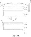
- FIG. 4 Exemplary temperature and pressure curves for a manufacturing process are illustrated, with which a layer composite 2 will be obtained from stacked layers of material.
- a temperature T and a pressure p are plotted over the time t.
- the FIG. 4 illustrates an autoclave process for the production of a composite layer 2.
- a heater is started and thus the temperature within the serving as a tool 1 autoclave increasingly increased.
- a compression pressure p1 above the ambient pressure is built up for compressing the layers of material stacked on one another and in particular the material layer 21 'of intumescent, porous material.
- the pressure p1 is already at a time t 1 , before the temperature has risen above a minimum threshold T0 at which the liquefied or liquid-containing resin begins to fill the pores of the compressed, intumescent material.
- the pressure p1 on the stacked layers of material is maintained over a large part of the production cycle in a period t 1 to t 6 , in which the temperature is first increased up to a first maximum temperature T1> T0, with T1 ⁇ 120 ° C.
- the corresponding temperature level is maintained for a period of t 2 to t 3 , before the temperature in a next stage (time t 4 > t 3 ) increases up to a further increased maximum temperature T2, with T2 ⁇ 175 ° C and this elevated temperature level until is held at a time t 5 .
- a slow cooling is allowed up to a time t 7 , wherein in the meantime, the pressure p is lowered again to ambient pressure.
- a defined residence time (t 3 - t 2 ) at the first maximum temperature in the amount of T1 ⁇ 120 ° C, serves for stress compensation during hardening, since it is to be ensured that the tool and layer composite have a balanced temperature before the actual hardening due to the increase to the second maximum temperature T2 ⁇ 175 ° C takes place.
- Middle of the FIG. 5 is again schematically a variant for the production of a composite layer 2 based on the temperature and pressure characteristics of FIG. 4 illustrated.
- a felt-like material layer 21 'of an intumescent, porous material, such as Tecnofire®, and a composite material layer 20' a resin layer 24 '(analogous to the adhesive layer 22'), for example, introduced in the manner of a thin film.
- the material layer 21 ' is densified from intumescent material and the resin of the resin layer 24' penetrate into it when subsequently the temperature is increased in stages.
- a mixing of the resin of the resin layer 24 'with a resin of an optionally pre-impregnated prepreg of the composite material layer 20' is excluded or extremely low and given only at the edge of the material layers 20 'and 21'.
- the composite layer 2 produced therefrom, from which an engine component is subsequently manufactured, thus has on an outer lateral surface only a thin layer 21 having a thickness d ⁇ 2 mm with intumescent material and with this sealing and stabilizing resin.
- the cured resin is in this case homogeneously distributed in the layer 21 with intumescent material and is present in the composite material layer 20 only at one edge, which adjoins the layer 21 with the intumescent material.
- the material layer 21 'of intumescent material is compacted, for example, by the applied pressure p1 to about 1/3 or 1/4 of the original thickness, before the stabilizing resin is introduced.
- the previous compression of the material layer 21 from intumescent material has proven to be particularly advantageous in this case if different resins with different viscosities are used in the different material layers 20 ', 20a', 20b ', 22', 23 'and 24'. Due to the early compression, it is achieved in particular that the different resins barely or not mix and, above all, that for the sealing and stabilization of the compressed intumescent material envisaged resin within the layer composite 2 produced significantly only in the layer 21 with the intumescent material occurs.
Description
Die Erfindung betrifft ein Verfahren zur Herstellung eines Schichtverbunds für ein Triebwerksbauteil sowie ein Triebwerksbauteil.The invention relates to a method for producing a composite layer for an engine component and an engine component.
Im Triebwerksbereich ist die Verwendung von Schichtverbunden für die Herstellung von Triebwerksbauteilen üblich. Hier werden faserverstärkte Verbundwerkstoffe in unterschiedlichen Konfigurationen und für verschiedene Triebwerksbauteile verwendet, um die gewünschten Materialeigenschaften durch die Kombination unterschiedlicher Werkstoffe zu erreichen. Ein Schichtverbund, aus dem ein Triebwerksbauteil hergestellt ist, besteht dabei aus mindestens zwei Schichten unterschiedlichen Materials, die stoff- und/oder formschlüssig miteinander verbunden sind. Bei Triebwerksbauteilen ist es ferner bekannt, diese mehrlagigen Schichtverbunde mit wenigstens einer feuerhemmenden oder feuerfesten Schicht zu versehen, um eine vorgegebene Feuerbeständigkeit oder Feuerfestigkeit zu erreichen. Mit dem entsprechenden Triebwerksbauteil kann dann beispielsweise ein abgeschotteter Bereich definiert werden, um eine Feuerausbreitung innerhalb des Triebwerks zu vermeiden oder zumindest in Grenzen zu halten.In the engine area, the use of laminates for the production of engine components is common. Here, fiber-reinforced composites in different configurations and for different engine components are used to achieve the desired material properties by combining different materials. A layer composite from which an engine component is made, consists of at least two layers of different material, which are connected to one another in a material and / or form-fitting manner. In engine components, it is also known to provide these multilayer laminates with at least one fire-retardant or refractory layer to achieve a predetermined fire resistance or fire resistance. With the appropriate engine component, for example, a foreclosed area can then be defined in order to prevent or at least limit fire propagation within the engine.
Insbesondere aus dem Baubereich ist es beim Brandschutz ferner bekannt, intumeszente, porige Baustoffe zu verwenden, die unter Hitzeeinwirkung anschwellen oder aufschäumen und damit ihr Volumen im Brandfall erheblich vergrößern. Das intumeszente Material dient dabei beispielsweise dazu eine veraschende Isolationsschicht auszubilden, durch die die Sauerstoffzufuhr und damit eine Ausbreitung einer Flamme behindert ist. Durch das sich ausdehnende intumeszente Material kann ferner auch eine Versiegelung eines kritischen Bereichs erreicht werden, sodass sich in diesem eine Flamme nicht weiter ausbreiten kann. Schichtverbunde mit wenigstens einer Schicht mit einem intumeszenten, porigen Material sind dabei beispielsweise aus der
Die Verwendung intumeszenter Materialien im Triebwerksbereich ist bisher nicht üblich. Dementsprechend gibt es derzeit allenfalls rudimentäre Überlegungen, einen Schichtverbund mit mindestens einer Schicht mit einem intumeszenten Material möglichst kompakt und leicht herzustellen, sodass eine Verwendung im Triebwerksbereich sinnvoll möglich ist.The use of intumescent materials in the engine area is not common. Accordingly, at present there are at most some rudimentary considerations for making a layer composite having at least one layer with an intumescent material as compact and easy as possible, so that use in the engine sector is meaningfully possible.
Der Erfindung liegt daher die Aufgabe zugrunde, einen Schichtverbund für die Erstellung eines Triebwerksbauteils bereitzustellen, der hinsichtlich der Anforderungen im Triebwerksbereich verbessert ist.The invention is therefore based on the object to provide a composite layer for the creation of an engine component, which is improved in terms of requirements in the engine area.
Diese Aufgabe wird mit einem Herstellungsverfahren nach Anspruch 1 gelöst.This object is achieved by a manufacturing method according to
Bei einem erfindungsgemäßen Herstellungsverfahren ist vorgesehen, dass zur Herstellung eines mehrlagigen Schichtverbundes
- mindestens eine Materiallage aus einem intumeszenten, porigen Material zusammen mit mindestens einer weiteren Materiallage für mindestens eine weitere Schicht des Schichtverbundes in einem Werkzeug aufeinandergeschichtet werden und
- nach dem Aufeinanderschichten der Materiallagen zumindest das intumeszente, porige Material durch ein aushärtendes Harz imprägniert wird.
- at least one layer of material made of an intumescent, porous material together with at least one further material layer for at least one further layer of the composite layer in a tool are stacked together and
- after the layers of material have been stacked on one another, at least the intumescent, porous material is impregnated by a hardening resin.
Erfindungsgemäß ist weiterhin vorgesehen, dass
- vor der Imprägnierung auf die aufeinandergeschichteten Materiallagen ein Druck aufgebracht wird, um wenigstens die Materiallage des intumeszenten, porigen Materials zu komprimieren, und
- durch das aushärtende Harz die Materiallage des intumeszenten, porigen Materials in dem Schichtverbund in seiner komprimierten Form gehalten und gegen ein Eindringen einer Flüssigkeit abgedichtet wird.
- prior to impregnation, applying pressure to the stacked layers of material to compress at least the layer of material of the intumescent, porous material, and
- held by the thermosetting resin, the material layer of the intumescent, porous material in the laminate in its compressed form and sealed against ingress of liquid.
Die Erfindung geht damit von dem Grundgedanken aus, sich die porige, gegebenenfalls auch poröse Eigenschaft eines intumeszenten Materials zu eigen zu machen, um dieses in einer komprimierten Form mit einem Harz respektive einer Harzmasse zu imprägnieren und damit einen herzustellenden Schichtverbund mit einem intumeszenten Material mit einer reduzierten Wanddicke auszubilden. Das zugeführte Harz dient dabei einerseits dazu, die Steifigkeit und Widerstandsfähigkeit der Schicht mit dem intumeszenten, porigen Material in dem Schichtverbund zu erhöhen sowie die Schicht mit dem intumeszenten Material stoffschlüssig mit der mindestens einen weiteren Schicht zu verbinden. Andererseits ist bei der erfindungsgemäßen Lösung über das ausgehärtete Harz die Materiallage des intumeszenten Materials in seiner komprimierten Form innerhalb des Schichtverbundes konserviert und abgedichtet.The invention is thus based on the basic idea of adopting the porous, possibly also porous, property of an intumescent material in order to achieve this impregnated in a compressed form with a resin or a resin composition and thus form a composite layer to be produced with an intumescent material having a reduced wall thickness. The supplied resin serves on the one hand to increase the rigidity and resistance of the layer with the intumescent, porous material in the laminate and to connect the layer with the intumescent material cohesively with the at least one further layer. On the other hand, in the solution according to the invention via the cured resin, the material layer of the intumescent material is preserved and sealed in its compressed form within the layer composite.
Durch die Verwendung eines intumeszenten, porigen Materials ist sichergestellt, dass das eingebrachte Harz respektive die eingebrachte Harzmasse von dem porigen respektive porösen intumeszenten Material aufgesaugt werden kann und damit das intumeszente Material von dem Harz durchtränkt und - nach dessen Aushärten - abgedichtet werden kann. An dem Triebwerksbauteil kann dann mittels des intumeszenten, durch das Harz abgedichteten Materials eine versiegelte Schicht gebildet werden, welche gegen Fluideinwirkungen resistent ist. Das intumeszente Material weist beispielsweise eine Porosität von über 70%, insbesondere im Bereich von mehr als 85% oder etwa 90% auf. Das intumeszente Material liegt dabei beispielsweise im Rohzustand filzartig als Materiallage aus einem Faservliesstoff vor. Beispielsweise wird eine Materiallage aus Tecnofire® der Technical Fibre Products Ltd. verwendet.By using an intumescent, porous material, it is ensured that the introduced resin or the introduced resin composition can be absorbed by the porous or porous intumescent material and thus the intumescent material can be impregnated by the resin and - after it has hardened - sealed. A sealed layer, which is resistant to fluid effects, can then be formed on the engine component by means of the intumescent material sealed by the resin. The intumescent material has, for example, a porosity of more than 70%, in particular in the range of more than 85% or about 90%. The intumescent material, for example, in the raw state felt like a felt before as a material layer of a nonwoven fabric. For example, a material layer made of Tecnofire® from Technical Fiber Products Ltd. used.
Bei einem erfindungsgemäß hergestellten Schichtverbund gast im Brandfall oder bei einer über einen kritischen Schwellwert ansteigenden Temperatur das Harz aus dem intumeszenten Material aus respektive vaporisiert und gibt das intumeszente Material somit frei, sodass es anschwellen oder aufschäumen kann, um brandhindernd oder feuerhemmend zu wirken. Dabei wird bereits durch das ausgasende Harz eine erste Volumenvergrößerung der Schicht mit dem intumeszenten Material gestattet, da das Harz diese Schicht nicht mehr in ihrer komprimierten Form hält. Zeitgleich oder nachfolgend zur Ausgasung des Harzes respektive zur Vaporisierung oder Verbrennung des Harzes erfolgt eine temperaturgetriebene Volumenvergrößerung des intumeszenten Materials. Derart kann beispielsweise durch das ausgasende Harz ein kontrolliertes Abflammen erreicht werden, bei dem in Harz getränktes Material des Schichtverbundes ähnlich einer Kerze abbrennt, bevor anschließend durch das (weitere) Aufquellen oder Aufschäumen des intumeszenten Materials eine Barriere erzeugt wird, die einer weiteren Flammenausbreitung entgegenwirkt. Die Schicht mit dem intumeszenten Material wirkt dabei im Brandfall oder bereits bei einer über einen kritischen Schwellwert ansteigenden Temperatur als eine Art Hitzeschild.In the case of a layer composite produced according to the invention, in the case of fire or at a temperature rising above a critical threshold, the resin is vaporized out of the intumescent material and releases the intumescent material so that it can swell or foam to act as a fire retardant or fire retardant. In this case, a first increase in volume of the layer with the intumescent material is already permitted by the outgassing resin, since the resin no longer holds this layer in its compressed form. At the same time or subsequently to the outgassing of the resin or for vaporization or combustion of the resin, a temperature-driven increase in volume of the intumescent material takes place. In this way, for example, a controlled flaming can be achieved by the outgassing resin, burned in resin soaked material of the composite layer similar to a candle, before then by the (further) swelling or foaming of the intumescent material, a barrier is generated, which counteracts further flame propagation. The layer with the intumescent material works in case of fire or already at a temperature above a critical threshold rising temperature as a kind of heat shield.
Durch die erfindungsgemäß vorgesehene Komprimierung wenigstens der Materiallage des intumeszenten, porigen Materials wird ferner erreicht, dass für dessen Abdichtung eine geringere Menge an Harz benötigt wird. Hiermit ist dann regelmäßig auch verbunden, dass eine äußere Schicht des Schichtverbundes weniger harzreich ist, da die Materiallage aus dem intumeszenten Material in dem fertiggestellten Schichtverbund üblicherweise eine Außenschicht auf der vor Feuer zu schützenden Seite bildet. Dies kann mit Blick auf eine geforderte Festigkeit und Steifigkeit des aus dem Schichtverbund hergestellten Triebwerksbauteils von Vorteil sein, insbesondere da hierdurch nur eine vergleichsweise dünne Schicht mit intumeszenten Material Verwendung finden muss und der zur Verfügung stehende Bauraum für die weitere, dann strukturtragende Schicht genutzt werden kann.By inventively provided compression of at least the material layer of the intumescent, porous material is further achieved that for the sealing of a smaller amount of resin is needed. This is then also regularly associated that an outer layer of the composite layer is less resinous, since the material layer of the intumescent material in the finished composite layer usually forms an outer layer on the fire to be protected side. This may be advantageous in view of a required strength and rigidity of the engine component produced from the layer composite, in particular since only a comparatively thin layer with intumescent material has to be used thereby and the available installation space for the further, then structure-carrying layer can be used ,
Die mindestens eine weitere Schicht respektive Materiallage zur Bildung des Schichtverbunds ist in einer Ausführungsvariante durch einen Verbundwerkstoff gebildet. Beispielsweise ist hierbei eine Materiallage für die weitere Schicht in Form eines Prepregs, also einem vorimprägnierten textilen Faser-Matrix-Halbzeug vorgesehen. Alternativ oder ergänzend kann eine Schicht aus einem anderen faserverstärkten Material vorgesehen sein.The at least one further layer or material layer for forming the layer composite is formed in one embodiment by a composite material. By way of example, a material layer for the further layer in the form of a prepreg, that is to say a preimpregnated textile fiber-matrix semifinished product, is provided in this case. Alternatively or additionally, a layer of another fiber-reinforced material may be provided.
In einer Ausführungsvariante eines erfindungsgemäßen Verfahrens ist für die Imprägnierung mit dem Harz eine Erwärmung der aufeinandergeschichteten Materiallagen bis wenigstens zu einer Mindesttemperatur vorgesehen. Die Erwärmung erfolgt hierbei zum Beispiel durch Erwärmung eines die aufeinandergeschichteten Materiallagen aufnehmenden Aufnahmeraumes des Werkzeugs. Dieser Aufnahmeraum ist beispielsweise durch eine Kavität in einer Formschale oder durch einen Autoklav definiert. Die Erwärmung dient beispielsweise zum Flüssighalten des eingebrachten Harzes oder zum Aushärten des Harzes bei einem warmhärtenden Harz.In one embodiment of a method according to the invention, a heating of the stacked material layers to at least a minimum temperature is provided for the impregnation with the resin. The heating takes place in this case, for example, by heating a receiving space of the tool which receives the stacked layers of material. This receiving space is defined for example by a cavity in a shell mold or by an autoclave. The heating serves, for example, to hold liquid of the introduced resin or to cure the resin in a thermosetting resin.
Es sei an dieser Stelle bereits angemerkt, dass die Einbringung des Harzes beispielsweise durch eine separate Harzlage erfolgen kann, die in den aufeinandergeschichteten Materiallagen vorgesehen ist. Alternativ kann eine Injektion des Harzes, beispielsweise im Wege eines Harzinjektionsverfahrens (englisch "(Resin Transfer Moulding", kurz "RTM") oder Vakuum unterstützt im Wege eines VARI- oder VARTM-Verfahrens erfolgen (kurz für Englisch "Vaccum Assisted Resin Injection" oder "Vacuum Assisted Resin Transfer Moulding"). Alternativ oder ergänzend kann bei einer Verwendung eines vorimprägnierten Prepregs das hierin enthaltene Harz im Zuge der Herstellung des Schichtverbundes durch Druckbeaufschlagung und Erwärmung verflüssigt und dann (auch) zur Durchtränkung des komprimierten intumeszenten Materials genutzt werden, das hierauf aufgeschichtet ist.It should be noted at this point that the introduction of the resin can be done for example by a separate resin layer, which is provided in the stacked layers of material. Alternatively, an injection of the resin, for example by means of a Resin Transfer Molding ("RTM") or vacuum assisted by a VARI or VARTM method (short for English "Vaccum Assisted Resin Injection" or "Vacuum Assisted Resin Transfer Alternatively or additionally, when using a prepreg prepreg, the resin contained therein may be liquefied by pressurization and heating in the course of making the laminate, and then used to impregnate the compressed intumescent material stacked thereon.
In einer Ausführungsvariante wird für die Imprägnierung eine Erwärmung der aufeinander geschichteten Materiallagen auf eine Mindesttemperatur von etwa 70 °C vorgesehen, um zu erreichen, dass das Harz respektive die Harzmasse das komprimierte intumeszente Material ausreichend durchtränkt. Der weiter Herstellungsprozess kann vorsehen, dass zur die Temperatur nachfolgend stufenweise bis zu einer ersten Maximaltemperatur von etwa 120°C und anschließend bis zu einer zweiten Maximaltemperatur von etwa 175°C erhöht wird. Eine definierte Verweilzeit bei einer ersten Maximaltemperatur, z.B. in Höhe von 120°C, dient zum Spannungsausgleich beim Härten, da sichergestellt werden soll, das Werkzeuge und Schichtverbund eine ausgeglichene Temperatur aufweisen, bevor die eigentliche Härtung durch die Erhöhung auf die zweite Maximaltemperatur erfolgt.In one embodiment, a heating of the stacked layers of material to a minimum temperature of about 70 ° C is provided for the impregnation, in order to achieve that the resin or the resin composition sufficiently impregnated the compressed intumescent material. The further manufacturing process may provide that the temperature is subsequently increased stepwise up to a first maximum temperature of about 120 ° C and then up to a second maximum temperature of about 175 ° C. A defined residence time at a first maximum temperature, e.g. in the amount of 120 ° C, serves to stress compensation during curing, since it is to be ensured that tools and layer composite have a balanced temperature before the actual hardening takes place by increasing to the second maximum temperature.
Um sicherzustellen, dass das intumeszente Material bereits auf eine gewünschte Dicke verdichtet ist, bevor das Harz in das intumeszente Material eindringt, ist in einer Variante vorgesehen, dass der Druck zum Komprimieren wenigstens der Materiallage des intumeszenten, porigen Materials aufgebracht wird, bevor die Mindesttemperatur, von zum Beispiel 70 °C, erreicht ist. Hierfür kann der Druck aufgebracht werden, wenn eine Heizeinrichtung zum Erwärmen der aufeinandergeschichteten Materiallagen auf die Mindesttemperatur aktiviert wird oder bevor eine solche Heizeinrichtung aktiviert wird. Der vorgesehene (Kompression-) Druck wird so zu demjenigen Zeitpunkt aufgebracht, an dem oder kurz nachdem die Heizeinrichtung aktiviert wird und damit ein Erwärmungsvorgang ausgelöst wird. Hierüber - wie auch bei einer nachgeschalteten Aktivierung der Heizeinrichtung - ist sichergestellt, dass der vorgegebene Druck in jedem Fall bereits auf die Materiallagen einwirkt, bevor die Mindesttemperatur erreicht ist.To ensure that the intumescent material is already densified to a desired thickness before the resin penetrates into the intumescent material, it is provided in a variant that the pressure for compressing at least the material layer of the intumescent, porous material is applied before the minimum temperature, of, for example, 70 ° C, is reached. For this purpose, the pressure can be applied if a heater for heating the stacked material layers is activated to the minimum temperature or before such a heater is activated. The intended (compression) pressure is applied at the time at which or shortly after the heater is activated and thus a heating process is triggered. By way of this - as with a subsequent activation of the heating device - it is ensured that the predetermined pressure in any case already acts on the material layers before the minimum temperature is reached.
In einer Ausführungsvariante liegt der vorgesehene (Kompression-) Druck zum Komprimieren wenigstens der Materiallage des intumeszenten Materials im Bereich von 5 bis 8 bar, insbesondere im Bereich von 5,5 bis 7,5 bar. Zum Beispiel ist ein Druck von etwa 7 bar vorgesehen.In one embodiment variant, the intended (compression) pressure for compressing at least the material layer of the intumescent material is in the range from 5 to 8 bar, in particular in the range from 5.5 to 7.5 bar. For example, a pressure of about 7 bar is provided.
Wie bereits vorstehend angesprochen, kann in einer Ausführungsvariante das zu Imprägnierung vorgesehene Harz als separate Materiallage in den aufgeschichteten Materiallagen vorgesehen sein. Das Harz wird hierbei beispielsweise als vergleichsweise dünne Schicht zwischen einer Materiallage des intumeszenten Materials und einer weiteren Materiallage aus einem Verbundwerkstoff vorgesehen. Bei anschließender Erwärmung und Kompression dringt dann das Harz in das intumeszente Material und den Verbundwerkstoff ein und verbindet diese. Ein solches Verfahren kann beispielsweise in einem Autoklav umgesetzt werden.As already mentioned above, in one embodiment variant, the resin intended for impregnation can be used as a separate material layer in the stacked layer Be provided material layers. The resin is provided here, for example, as a comparatively thin layer between a material layer of the intumescent material and a further material layer made of a composite material. Upon subsequent heating and compression, the resin then penetrates and bonds the intumescent material and the composite. Such a method can be implemented, for example, in an autoclave.
Alternativ oder ergänzend kann die mindestens eine Materiallage für die mindestens eine weitere Schicht des Schichtverbundes vorimprägniert sein und damit das zu Imprägnierung des intumeszenten, porigen Materials vorgesehene Harz zumindest teilweise aus der vorimprägnierten Materiallage stammen. Insbesondere in diesem Zusammenhang kann sich gegebenenfalls die vorstehend erläuterte Variante, bei der der (Kompression-) Druck zum Komprimieren wenigstens der Materiallage des intumeszenten Materials frühzeitig aufgebracht wird, bevor eine Erwärmung der auf einander geschichteten Materiallagen erfolgt, als besonders vorteilhaft erweisen. Durch den frühzeitig aufgebrachten Druck kann ein Harz für die Konservierung der komprimierten Form des intumeszenten Materials und dessen Abdichtung in vergleichsweise geringer Menge vorgesehen werden und bereits frühzeitig in das intumeszente Material eindringen, bevor durch eine nachfolgende Erwärmung eine Verflüssigung des (zusätzlichen) Harzes aus der vorimprägnierten Materiallage auftritt. Damit kann eine gegebenenfalls unerwünschte Vermischung unterschiedlicher Harze und mithin Harzsysteme innerhalb des Schichtverbundes effektiv vermieden werden.Alternatively or additionally, the at least one layer of material for the at least one further layer of the layer composite can be preimpregnated and thus the resin intended for impregnating the intumescent, porous material at least partially originate from the preimpregnated material layer. In particular, in this context, if appropriate, the above-described variant in which the (compression) pressure for compressing at least the material layer of the intumescent material is applied early before a heating of the material layers stacked on one another, can prove to be particularly advantageous. Due to the early applied pressure, a resin for the preservation of the compressed form of the intumescent material and its sealing in comparatively small amount can be provided and penetrate early in the intumescent material before liquefaction of the (additional) resin from the pre-impregnated by subsequent heating Material situation occurs. Thus, any undesired mixing of different resins and therefore resin systems within the layer composite can be effectively avoided.
Für eine stoffschlüssige Verbindung der aufeinandergeschichteten Materiallagen kann in einer Ausführungsvariante mindestens eine Klebemittellage vorgesehen sein. Diese Klebemittellage kann ein - gegebenenfalls zusätzliches - Harz enthalten, das zur Imprägnierung des intumeszenten Materials zumindest teilweise genutzt wird.For a cohesive connection of the layered layers of material, at least one layer of adhesive may be provided in a variant embodiment. This adhesive layer may contain a - optionally additional - resin, which is at least partially used to impregnate the intumescent material.
In einem Ausführungsbeispiel ist als Werkzeug ein Autoklav genutzt, mittels dem der Druck zum Komprimieren wenigstens der Materiallage des intumeszenten, porigen Materials auf die aufeinandergeschichteten Materiallagen aufgebracht wird. Ein hier vorgesehener Herstellungsprozess kann dann beispielsweise insbesondere einen Autoklavenzyklus vorgesehen, bei dem bereits frühzeitig der zur Komprimierung des intumeszenten Materials vorgesehene Druck aufgebracht wird, bevor eine Erwärmung der aufeinandergeschichteten Materiallagen erfolgt.In one embodiment, an autoclave is used as a tool, by means of which the pressure for compressing at least the material layer of the intumescent, porous material is applied to the stacked material layers. A manufacturing process provided here can then, for example, in particular provide an autoclave cycle in which the pressure intended for compressing the intumescent material is applied at an early stage before the stacked material layers are heated.
Das verwendete intumeszente, porige Material ist beispielsweise derart gewählt und der hierauf aufgebrachte Druck derart hoch eingestellt, dass die Schicht mit dem intumeszenten, porigen Material in dem hergestellten Schichtverbund eine Dicke von 2,3 mm nicht übersteigt. Insbesondere liegt eine (Schicht-) Dicke beispielsweise im Bereich von 0,4 mm bis 1,5 mm. Die Schicht komprimierten, intumeszenten Materials ist somit vergleichsweise dünn und in seinem komprimierten Zustand durch die Bindung mittels des Harzes arretiert, quasi "eingefroren". Durch die intumeszente Eigenschaft des Materials kann diese Schicht jedoch auf ein Vielfaches ihres Volumens anschwellen, um hierdurch eine feuerhemmende Barriere auszubilden.The intumescent, porous material used is chosen, for example, and the pressure applied thereto is set so high that the layer with the intumescent, porous material in the layer composite produced does not exceed a thickness of 2.3 mm. In particular, a (layer) thickness is, for example, in the range of 0.4 mm to 1.5 mm. The layer of compressed, intumescent material is thus comparatively thin and in its compressed state locked by the binding by means of the resin, quasi "frozen". However, due to the intumescent nature of the material, this layer can swell to a multiple of its volume, thereby forming a fire-retardant barrier.
Ein weiterer Aspekt der erfindungsgemäßen Lösung ist die Bereitstellung eines Schichtverbunds, aus dem ein Triebwerksbauteil zumindest teilweise herstellbar ist.A further aspect of the solution according to the invention is the provision of a layer composite from which an engine component can be produced at least partially.
Ein solcher Schichtverbund ist hierbei mehrlagig aufgebaut und weist mindestens eine Schicht mit einem intumeszenten, porigen Material sowie mindestens eine weitere Schicht, zum Beispiel aus einem Verbundwerkstoff, auf. Zur Bildung der Schicht mit dem intumeszenten, porigen Material ist eine Materiallage aus intumeszenten, porigen Material durch ein Harz imprägniert, das in seinem ausgehärteten Zustand die Materiallage aus intumeszenten, porigen Material in dem Schichtverbund in einer komprimierten Form hält und gegen Eindringen einer Flüssigkeit, aber auch gegen ein Eindringen von Feuchtigkeit und Gasen abdichtet.Such a layer composite is in this case constructed in multiple layers and has at least one layer with an intumescent, porous material and at least one further layer, for example of a composite material. To form the layer with the intumescent, porous material, a material layer of intumescent, porous material is impregnated by a resin which, in its hardened state, holds the material layer of intumescent, porous material in the layer composite in a compressed form and against the ingress of a liquid also seals against ingress of moisture and gases.
Ein solcher Schichtverbund kann somit durch ein erfindungsgemäßes Herstellungsverfahren hergestellt werden. Dementsprechend gelten vorstehend und nachstehend genannte Vorteile und Merkmale von Ausführungsvarianten eines erfindungsgemäßen Herstellungsverfahrens auch für Varianten eines solchen Schichtverbundes und umgekehrt.Such a layer composite can thus be produced by a production method according to the invention. Accordingly, advantages and features of embodiments of a manufacturing method according to the invention mentioned above and below also apply to variants of such a layer composite and vice versa.
Erfindungsgemäß ist mit einem solchen Schichtverbund beispielsweise ein Triebwerksbauteil für ein Gasturbinentriebwerk hergestellt. Ein solches Triebwerksbauteil kann beispielsweise ein Triebwerksgehäuse (auch als Gondel oder englisch "nacelle" bezeichnend), ein Fangehäuse, eine Wandung eines Bypasskanals oder ein Verkleidungsbauteil für die Einhausung mindestens einer Leitung und/oder einer elektronischen und/oder Fluid führenden Komponente und/oder Baugruppe innerhalb des Triebwerks sein.According to the invention, for example, an engine component for a gas turbine engine is produced with such a layer composite. Such an engine component may, for example, an engine housing (also referred to as gondola or English "nacelle"), a fan housing, a wall of a bypass duct or a trim component for the enclosure of at least one line and / or electronic and / or fluid leading component and / or assembly to be inside the engine.
Mögliche Ausführungsvarianten der erfindungsgemäßen Lösung sind anhand der beigefügten Figuren exemplarisch veranschaulicht.Possible embodiments of the solution according to the invention are illustrated by way of example with reference to the attached figures.
Hierbei zeigen:
Figur 1- schematisch und in Querschnittsansicht ein Gasturbinentriebwerk in Form eines Turbofan-Triebwerks, an dessen Triebwerksbauteilen ein erfindungsgemäß hergestellter Schichtverbund Verwendung findet;
Figur 2- eine detailliertere Darstellung des Triebwerks der
Figur 1 in perspektivischer Ansicht ohne Darstellung eines Triebwerksgehäuses; - Figuren 3A-3C
- schematisch unterschiedliche Ausführungsvarianten eines erfindungsgemäßen Herstellungsverfahrens unter Veranschaulichung unterschiedlicher Materiallagen zur Herstellung eines mehrlagigen Schichtverbunds;
- Figur 4
- ein Diagramm, in dem ein Temperaturverlauf und ein Druckverlauf für eine mit einem Autoklav ausgeführte Variante eines erfindungsgemäßen Herstellungsverfahrens über der Zeit aufgetragen sind;
- Figur 5
- schematisch eine weitere Ausführungsvariante eines erfindungsgemäßen Herstellungsverfahrens, bei dem eine separate Harzlage zwischen einer Materiallage aus intumeszenten Material und einer Materiallage aus einem Verbundwerkstoff zur Erzeugung eines Schichtverbunds verwendet werden.
- FIG. 1
- schematically and in cross-sectional view of a gas turbine engine in the form of a turbofan engine, on the engine components of which an inventively produced layer composite is used;
- FIG. 2
- a more detailed view of the engine of the
FIG. 1 in perspective view without representation of an engine housing; - Figures 3A-3C
- schematically different embodiments of a manufacturing method according to the invention illustrating different layers of material for producing a multilayer composite layer;
- FIG. 4
- a diagram in which a temperature profile and a pressure curve are plotted over time for an executed with an autoclave variant of a manufacturing method according to the invention;
- FIG. 5
- schematically a further embodiment of a manufacturing method according to the invention, in which a separate resin layer between a material layer of intumescent material and a material layer of a composite material are used to produce a composite layer.
Die
Die über den Verdichter V in den Primärstromkanal geförderte Luft gelangt in einen Brennkammerabschnitt BK des Kerntriebwerks, in dem die Antriebsenergie zum Antreiben der Turbine TT erzeugt wird. Die Turbine TT weist hierfür eine Hochdruckturbine 13, eine Mitteldruckturbine 14 und einen Niederdruckturbine 15 auf. Die Turbine TT treibt dabei über die bei der Verbrennung frei werdende Energie die Rotorwelle RS und damit den Fan F an, um über die die in den Bypasskanal B geförderte Luft den erforderlichen Schub zu erzeugen. Sowohl die Luft aus dem Bypasskanal B als auch die Abgase aus dem Primärstromkanal des Kerntriebwerks strömen über einen Auslass A am Ende des Triebwerks T aus. Der Auslass A weist hierbei üblicherweise eine Schubdüse mit einem zentral angeordneten Austrittskonus C auf.The air conveyed into the primary flow passage via the compressor V enters a combustion chamber section BK of the core engine in which the driving power for driving the turbine TT is generated. For this purpose, the turbine TT has a high-
Anhand der
Anhand der
Hierbei sei zum Beispiel verwiesen auf das Fangehäuse FC des Fans F sowie innerhalb des Bypasskanals B liegende Verkleidungen VK1 und VK2. Über die Verkleidungen VK1 und VK2 sind beispielsweise Leitungen und/oder elektronische Komponenten aerodynamisch eingehaust. Beispielsweise bildet ein Verkleidungsbauteil VK2 hierfür eine Hinterkante HK aus, die in Strömungsrichtung des in dem Bypasskanals B im Betrieb des Triebwerks strömenden Fluids spitz zuläuft. Die Verkleidungsbauteile VK1 und VK2 werden üblicherweise auch im englischen als "fairings" oder "splitter fairing" bezeichnet.Here, for example, refer to the fan housing FC of the fan F and within the bypass channel B lying panels VK1 and VK2. About the panels VK1 and VK2, for example, lines and / or electronic components are aerodynamically housed. For example, a lining component VK2 forms for this purpose a trailing edge HK, which tapers in the flow direction of the fluid flowing in the bypass channel B during operation of the engine. The trim components VK1 and VK2 are commonly referred to in English as "fairings" or "splitter fairing".
Alternativ oder ergänzend zu den vorstehend genannten Triebwerksbauteilen können auch Verkleidungen oder Gehäuse, die innerhalb eines Hohlraums in dem Triebwerksgehäuse N untergebracht sind, aus einem Schichtverbund hergestellt sein, der aus Brandschutzgründen mit einem feuerfesten oder feuerhemmenden Material versehen ist.As an alternative or in addition to the abovementioned engine components, linings or housings which are accommodated within a cavity in the engine housing N can also be produced from a layer composite which, for fire protection reasons, is provided with a refractory or fire-retardant material.
Grundsätzlich besteht bei allen Schichtverbunden im Triebwerksbereich das Bestreben, diese dünnwandig und vor allem leicht auszugestalten, ohne hierbei selbstverständlich auf einen effektiven Brandschutz verzichten zu müssen. In diesem Zusammenhang schlägt die erfindungsgemäße Lösung vor, einen Schichtverbund, wie zum Beispiel den Schichtverbund 2a oder 2b, mit einem intumeszenten, porigen Material und zusätzlich nach einem Verfahren herzustellen, bei dem eine Materiallage des intumeszenten, porigen Materials in komprimierter Form mit einem Harz imprägniert und in seiner komprimierten Form gehalten und abgedichtet wird.Basically, there is the effort in all layer composites in the engine area, these thin-walled and above all easy to design, without of course having to do without effective fire protection. In this connection, the solution according to the invention proposes to produce a layer composite, such as layer composite 2a or 2b, with an intumescent, porous material and additionally by a process in which a material layer of the intumescent, porous material is impregnated in compressed form with a resin and held and sealed in its compressed form.
Über die Verwendung eines intumeszenten Materials wird somit in einen Schichtverbund, der vorzugsweise mehrere Verbundwerkstoffe integriert, mindestens eine Schicht vorgesehen, die bei über einen Schwellwert ansteigenden Temperatur (z.B. von 195°C) und insbesondere bei einem Feuer innerhalb des Triebwerks T um ein Vielfaches ihres ursprünglichen Volumens ansteigt und hierdurch eine isolierende Schicht nach Art eines Hitzeschild bereitstellt und/oder durch ihre Volumenvergrößerung Bereiche gezielt verschließt, sodass sich eine Flamme nicht ohne weiteres in diese Bereiche hinein ausbreiten kann.By using an intumescent material, at least one layer is thus provided in a layer composite, which preferably integrates a plurality of composite materials, which at a temperature rising above a threshold (eg of 195 ° C) and in particular in a fire within the engine T by a multiple of their original volume increases and thereby provides an insulating layer in the manner of a heat shield and / or targeted by their increase in volume areas closes, so that a flame can not easily spread into these areas.
In einer anhand der
Anschließend wird über ein Harz aus einer Harzzufuhr 10 des Werkzeugs 1 zur Imprägnierung der komprimierten Materiallagen 20' und 21' eingebracht. Insbesondere das vorzugsweise hochporige intumeszente Material der Materiallage 21' wird jeweils mit dem Harz gefüllt, sodass nicht nur die beiden Materiallagen 20' und 21' über das Harz stoffschlüssigen miteinander verbunden sind, sondern auch die Materiallage 21' des intumeszenten Materials in ihrer komprimierten Form gehalten und abgedichtet ist. Das ausgehärtete Harz konserviert somit die komprimierte Form des intumeszenten Materials und dichtet dieses gegen das Eindringen von Flüssigkeiten nach außen ab. Das Einbringen des Harzes über die Harzzufuhr 10 erfolgt beispielsweise nach Art eines Harzinjektionsverfahrens (RTM-Verfahrens) oder Vakuum unterstützt in einem VARI- oder VARTM-Verfahren.Subsequently, a resin from a
Für die Bereitstellung einer Materiallage 21' aus einem intumeszenten, hochporigen Material bietet sich Beispiel Tecnofire® der Technical Fibre Products Ltd. an. Jedoch sind auch grundsätzlich andere intumeszente Materialien geeignet, insbesondere solche die filzartig und in Form eines flexiblen Faservliesstoffes vorliegen.To provide a material layer 21 'of an intumescent, highly porous material, Tecnofire® of Technical Fiber Products Ltd. can be used as an example. at. However, in principle, other intumescent materials are also suitable, in particular those which are felt-like and in the form of a flexible nonwoven fabric.
Bei einem entsprechend der Variante der
Bei einer über einen Schwellwert, zum Beispiel in Höhe von etwa 195°C, ansteigenden Temperatur im Bereich der mit dem intumeszenten Material versehenen Schicht 21 oder einer Flammenbildung in diesem Bereich gast das ausgehärtete Harz des Schichtverbunds 2 aus. Das intumeszente Material der Schicht 21 wird dann über das Harz nicht mehr in seiner komprimierten Form gehalten und kann temperaturbedingt (zusätzlich) anschwellen oder aufschäumen. Die hiermit verbundene Volumenvergrößerung der mit dem intumeszenten Material versehenen Schicht 21 kann nach Art eines Hitzeschilds als feuerhemmende oder feuerfeste Barriere dienen. Alternativ oder ergänzend kann über die Volumenvergrößerung ein Bereich des Triebwerks T abgeschottet werden, in Abhängigkeit davon, welches Triebwerksbauteil aus dem Schichtverbund 2 hergestellt wird.In the case of a temperature rising in the region of the
Bei der Variante der
Bei der Variante der
In allen drei vorstehend erläuterten Varianten der
Im Übrigen ist beachtlich, dass bei einer Verwendung einer vorimprägnierten Verbundwerkstofflage 20' oder 20a', 20b' über eine frühzeitige Aufbringung des Druckes p erreicht werden kann, dass sich das zur Imprägnierung des komprimierten, intumeszenten Materials vorgesehene Harz nicht oder kaum mit einem für die Vorimprägnierung genutzten Harzes der jeweiligen Verbundwerkstofflage 20' oder 20a', 20b' vermischt.Incidentally, it is noteworthy that when using a pre-impregnated
Mit dem Diagramm der
Gleich zu Beginn des anhand der
Der Druck p1 auf die aufeinandergeschichteten Materiallagen wird über einen Großteil des Herstellungszyklus in einem Zeitraum t1 bis t6 aufrechterhalten, in dem die Temperatur zunächst bis zu einer ersten Maximaltemperatur T1 > T0, mit T1≈120°C erhöht wird. Das entsprechende Temperaturniveau wird hierbei für einen Zeitraum t2 bis t3 gehalten, bevor die Temperatur in einer nächsten Stufe (Zeitpunkt t4>t3) bis zu einer nochmals erhöhten Maximaltemperatur T2, mit T2≈175 °C erhöht und dieses erhöhte Temperaturniveau bis zu einem Zeitpunkt t5 gehalten wird. Danach wird ein langsames Abkühlen bis zu einem Zeitpunkt t7 gestattet, wobei in der Zwischenzeit auch der Druck p wieder auf Umgebungsdruck abgesenkt wird. Bei der Variante der
Mitte der
Bei den vorstehend erläuterten Ausführungsvarianten ist die Materiallage 21' aus intumeszenten Material beispielsweise durch den angelegten Druck p1 auf etwa 1/3 oder 1/4 der ursprünglichen Dicke verdichtet, bevor das stabilisierende Harz eingebracht wird. Die vorherige Kompression der Materiallage 21 aus intumeszenten Material hat sich hierbei insbesondere als vorteilhaft erwiesen, wenn unterschiedliche Harze mit verschiedener Viskositäten in den unterschiedlichen Materiallagen 20', 20a', 20b', 22', 23' und 24' zum Einsatz kommen. Durch die frühzeitige Kompression wird hierbei insbesondere erreicht, dass sich die unterschiedlichen Harze kaum oder nicht vermischen und vor allem das für die Abdichtung und Stabilisierung des komprimierten intumeszenten Materials vorgesehene Harz innerhalb des hergestellten Schichtverbunds 2 maßgeblich nur in der Schicht 21 mit dem intumeszenten Material vorkommt.In the embodiments described above, the material layer 21 'of intumescent material is compacted, for example, by the applied pressure p1 to about 1/3 or 1/4 of the original thickness, before the stabilizing resin is introduced. The previous compression of the
- 11
- Werkzeug / AutoklavTool / autoclave
- 1010
- Harzzufuhrresin supply
- 1111
- NiederdruckverdichterLow-pressure compressor
- 1212
- HochdruckverdichterHigh-pressure compressors
- 1313
- HochdruckturbineHigh-pressure turbine
- 1414
- MitteldruckturbineIntermediate pressure turbine
- 1515
- NiederdruckturbineLow-pressure turbine
- 2, 2a, 2b2, 2a, 2b
- Schichtverbundlayer composite
- 2020
- Verbundwerkstoffschicht / VerbundlaminatComposite layer / composite laminate
- 20'20 '
- Verbundwerkstofflage / PrepregComposite material / prepreg
- 20a, 20b20a, 20b
- Separate VerbundwerkstoffschichtSeparate composite layer
- 20a', 20b'20a ', 20b'
- Separate VerbundwerkstofflageSeparate composite layer
- 2121
- Schicht mit intumeszenten MaterialLayer with intumescent material
- 21'21 '
- Materiallage aus intumeszenten MaterialMaterial layer of intumescent material
- 22'22 '
- KlebemittellageAdhesive layer
- 2323
- WabenstrukturschichtHoneycomb layer
- 23'23 '
- Wabenlagehoneycomb location
- 24'24 '
- Harzlageresin layer
- AA
- Auslassoutlet
- BB
- Bypasskanalbypass channel
- BKBK
- Brennkammerabschnittcombustor section
- CC
- Austrittskonusexit cone
- dd
- Dickethickness
- Ee
- Einlass / IntakeInlet / Intake
- FF
- Fanfan
- FCFC
- Fangehäusefan casing
- HKHK
- Hinterkantetrailing edge
- MM
- Mittelachse / RotationsachseCentral axis / rotation axis
- NN
- TriebwerksgehäuseEngine casing
- pp
- (Kompressions-) Druck(Compression) pressure
- RR
- Eintrittsrichtungentry direction
- RSRS
- Rotorwellerotor shaft
- TT
- Turbofan-TriebwerkTurbofan engine
- TTTT
- Turbineturbine
- UU
- Umfangsrichtungcircumferentially
- VV
- Verdichtercompressor
- VK1, VK2VK1, VK2
- Verkleidungpaneling
Claims (13)
- Method for manufacturing a layer bonding from which an engine component (FC, N, VK1, VK2) can be at least partially manufactured, wherein the layer bonding (2, 2a, 2b) has a multi-layer structure and at least one layer (21) with an intumescent poriferous material as well as at least one further layer (20, 20a, 20b, 23), wherein for manufacturing the layer bonding (2, 2a, 2b)- at least one material layer (21') from intumescent poriferous material and at least one material layer (20', 20a', 20b', 23') for the at least one further layer (20, 20a, 20b, 23) are stacked on top of each other in a tool (1), and- at least the intumescent poriferous material is impregnated by means of curing resin after the material layers (20', 20a', 20b', 23', 21') have been stacked,characterized in that- a pressure (p1) is applied to the material layers stacked on top of each other (20', 20a', 20b', 23', 21') prior to the impregnation so as to compress at least the material layer (21') of the intumescent poriferous material, and- the material layer (21') of intumescent poriferous material is held in its compressed shape and sealed against the entry of any liquid in the layer bonding (2, 2a, 2b) by means of the curing resin.
- Method according to claim 1, characterized in that heating of the material layers stacked on top of each other (20', 20a', 20b', 23', 21') up to at least a minimum temperature (T0) is carried out for performing the impregnation with the resin.
- Method according to claim 2, characterized in that the pressure (p1) for compressing at least the material layer (21') of the intumescent poriferous material is applied before the minimum temperature (T1) is reached.
- Method according to claim 2 or 3, characterized in that the pressure (p1) for compressing at least the material layer (21') of the intumescent poriferous material is applied when a heating appliance is activated for heating (T1) the material layers stacked on top of each other (20', 20a', 20b', 23', 21') to the minimum temperature (T1), or before the heating appliance is activated.
- Method according to one of the preceding claims, characterized in that the resin provided for impregnation is provided as a separate material layer (24') in the material layers (20', 20a', 20b', 23', 21') stacked on top of each other.
- Method according to claim 5, characterized in that a separate resin layer (24') is provided between the at least one material layer (21') from intumescent poriferous material and the at least one material layer (20', 20a', 20b', 23').
- Method according to one of the preceding claims, characterized in that the at least one material layer (20', 20a', 20b') for the at least one further layer (20, 20a, 20b) is pre-impregnated, and the resin provided for impregnating the intumescent poriferous material comes at least partially from the pre-impregnated material layer (20', 20a', 20b', 23', 21').
- Method according to one of the preceding claims, characterized in that at least one bonding agent layer (22') is provided in the material layers stacked on top of each other (20', 20a', 20b', 23', 21').
- Method according to claim 8, characterized in that the at least one bonding agent layer (24') contains a resin, and a resin coming at least partially from the bonding agent layer (20', 20a', 20b', 23', 21') is provided for impregnating the intumescent poriferous material.
- Method according to one of the preceding claims, characterized in that an autoclave is used as the tool (1) by means of which the pressure (p1) for compressing at least the material layer (21') of the intumescent poriferous material is applied to the material layers stacked on top of each other (20', 20a', 20b', 23', 21').
- Method according to one of the preceding claims, characterized in that the layer (21) with the intumescent poriferous material does not exceed a thickness (d) of 2.3 mm, in particular has a thickness (d) in the range of 0.4 mm to 1.5 mm, in the manufactured layer bonding (2, 2a, 2b).
- Engine component for a gas turbine engine (T) that is made at least partially of a layer bonding (2, 2a, 2b) which has a multi-layer structure and comprises at least one layer (21) with an intumescent poriferous material as well as at least one further layer (20, 20a, 20b, 23), wherein at least the intumescent poriferous material is impregnated with a cured resin, and a material layer (21') of the intumescent poriferous material is kept in a compressed shape and sealed against the entry of any liquid by the curing resin to form the layer (21) with the intumescent poriferous material in the layer bonding (2, 2a, 2b).
- Engine component according to claim 12, characterized in that the engine component is an engine housing (N), a fan housing (FC), a wall of a bypass channel (B), or a cladding component (VK1, VK2) for housing at least one conduit and/or an electronic component and/or a component conducting a fluid and/or assembly group inside the engine (T).
Applications Claiming Priority (1)
| Application Number | Priority Date | Filing Date | Title |
|---|---|---|---|
| DE102016217234.4A DE102016217234A1 (en) | 2016-09-09 | 2016-09-09 | Manufacturing process for a composite layer with intumescent material, layer composite and engine component |
Publications (2)
| Publication Number | Publication Date |
|---|---|
| EP3293000A1 EP3293000A1 (en) | 2018-03-14 |
| EP3293000B1 true EP3293000B1 (en) | 2018-08-15 |
Family
ID=59772400
Family Applications (1)
| Application Number | Title | Priority Date | Filing Date |
|---|---|---|---|
| EP17187735.0A Active EP3293000B1 (en) | 2016-09-09 | 2017-08-24 | Method of manufacturing a multilayer composite with intumescent material and engine component |
Country Status (3)
| Country | Link |
|---|---|
| US (1) | US20180072036A1 (en) |
| EP (1) | EP3293000B1 (en) |
| DE (1) | DE102016217234A1 (en) |
Families Citing this family (2)
| Publication number | Priority date | Publication date | Assignee | Title |
|---|---|---|---|---|
| GB201804569D0 (en) * | 2018-03-22 | 2018-05-09 | Rolls Royce Plc | Casing assembly |
| DE102020200820A1 (en) | 2020-01-23 | 2021-07-29 | Rolls-Royce Deutschland Ltd & Co Kg | Manufacturing process for a layer composite and engine component |
Family Cites Families (8)
| Publication number | Priority date | Publication date | Assignee | Title |
|---|---|---|---|---|
| US4801496A (en) * | 1986-06-24 | 1989-01-31 | The Boeing Company | Composite member with integrated thermal protection |
| US5281388A (en) * | 1992-03-20 | 1994-01-25 | Mcdonnell Douglas Corporation | Resin impregnation process for producing a resin-fiber composite |
| GB9807028D0 (en) | 1998-04-02 | 1998-06-03 | Technical Fibre Products Limit | Intumescent material |
| US20050136761A1 (en) * | 2003-12-17 | 2005-06-23 | Daikin Industries, Ltd. | Fire-Retardant Composite Material |
| EP1912782A4 (en) * | 2005-07-27 | 2011-11-23 | Milwaukee Composites Inc | Fire retardant panel apparatus and method of making and using same |
| AU2006235991A1 (en) | 2005-11-11 | 2007-05-31 | Advanced Composite Structures Limited | Fire retardant surfacing material for polymer composites |
| EP2602104A1 (en) * | 2011-12-09 | 2013-06-12 | EADS Deutschland GmbH | Fiber-reinforced composite material with improved fire resistance, and structural component made thereof |
| KR20170125008A (en) * | 2015-02-27 | 2017-11-13 | 도레이 카부시키가이샤 | Resin supply material, method for using reinforcing fibers, preform, and method for producing fiber-reinforced resin |
-
2016
- 2016-09-09 DE DE102016217234.4A patent/DE102016217234A1/en not_active Withdrawn
-
2017
- 2017-08-24 EP EP17187735.0A patent/EP3293000B1/en active Active
- 2017-09-07 US US15/697,829 patent/US20180072036A1/en not_active Abandoned
Non-Patent Citations (1)
| Title |
|---|
| None * |
Also Published As
| Publication number | Publication date |
|---|---|
| EP3293000A1 (en) | 2018-03-14 |
| DE102016217234A1 (en) | 2018-03-15 |
| US20180072036A1 (en) | 2018-03-15 |
Similar Documents
| Publication | Publication Date | Title |
|---|---|---|
| EP1916091B1 (en) | Method for manufacturing composite fibrous components | |
| EP1444090B1 (en) | Method and device for producing fibre-reinforced plastic components | |
| EP1181149B1 (en) | Method and device for producing fibre-reinforced components using an injection method | |
| DE102008015070B3 (en) | VAP autoclave method for producing fiber composite components and device therefor | |
| EP1420940A2 (en) | Method and device for producing fiber-reinforced components by an injection method | |
| DE19915083C1 (en) | Fiber-reinforced component manufacture involving autoclave molding of a combination of prepreg-based simple parts and resin infusion-based complex textile parts | |
| DE102012207950A1 (en) | Method for producing a fiber composite component, support core and fiber composite component | |
| EP2105284A1 (en) | Method for manufacturing composite fibrous components | |
| EP3293000B1 (en) | Method of manufacturing a multilayer composite with intumescent material and engine component | |
| WO2020069982A1 (en) | Infusion device and method for producing fiber-reinforced composite parts | |
| DE102009047798A1 (en) | Turbine blade, in particular end-stage blade for a steam turbine | |
| DE102006023865B4 (en) | Process for producing a fiber-reinforced component | |
| EP2558279B1 (en) | Method and device for producing a composite molded part from fiber-reinforced plastic | |
| DE102005003713A1 (en) | Fiber reinforced sandwich structure with hollow core made by vacuum-assisted impregnation, e.g. for aircraft use, includes a separation layer to control resin penetration | |
| EP2003388B1 (en) | Heat insulating body and method for producing same | |
| EP2890552B1 (en) | Method for producing a rotor blade and rotor blade of a wind turbine | |
| EP1393883B1 (en) | Device, tool system and method for the production of fiber reinforced composite parts by a temperature and pressure controlled injection process | |
| EP3296099B1 (en) | Method for producing an engine component by means of a blank from intumescent material | |
| DE102007004314B4 (en) | Method for producing a fiber composite component with at least one interspersed region for an aircraft or spacecraft | |
| EP1798418A2 (en) | Fan impeller and its production method | |
| EP2513387B1 (en) | Concrete formwork board and method for producing a concrete formwork board | |
| DE102020200820A1 (en) | Manufacturing process for a layer composite and engine component | |
| AT511676B1 (en) | COMPOUND AND METHOD FOR PRODUCING A COMPOSITE ELEMENT | |
| DE102014004387A1 (en) | Composite component and method for its production | |
| AT510083A2 (en) | FIBER-REINFORCED COMPOSITE COMPONENT |
Legal Events
| Date | Code | Title | Description |
|---|---|---|---|
| PUAI | Public reference made under article 153(3) epc to a published international application that has entered the european phase |
Free format text: ORIGINAL CODE: 0009012 |
|
| STAA | Information on the status of an ep patent application or granted ep patent |
Free format text: STATUS: REQUEST FOR EXAMINATION WAS MADE |
|
| 17P | Request for examination filed |
Effective date: 20180108 |
|
| AK | Designated contracting states |
Kind code of ref document: A1 Designated state(s): AL AT BE BG CH CY CZ DE DK EE ES FI FR GB GR HR HU IE IS IT LI LT LU LV MC MK MT NL NO PL PT RO RS SE SI SK SM TR |
|
| AX | Request for extension of the european patent |
Extension state: BA ME |
|
| GRAP | Despatch of communication of intention to grant a patent |
Free format text: ORIGINAL CODE: EPIDOSNIGR1 |
|
| STAA | Information on the status of an ep patent application or granted ep patent |
Free format text: STATUS: GRANT OF PATENT IS INTENDED |
|
| INTG | Intention to grant announced |
Effective date: 20180410 |
|
| GRAS | Grant fee paid |
Free format text: ORIGINAL CODE: EPIDOSNIGR3 |
|
| GRAA | (expected) grant |
Free format text: ORIGINAL CODE: 0009210 |
|
| STAA | Information on the status of an ep patent application or granted ep patent |
Free format text: STATUS: THE PATENT HAS BEEN GRANTED |
|
| AK | Designated contracting states |
Kind code of ref document: B1 Designated state(s): AL AT BE BG CH CY CZ DE DK EE ES FI FR GB GR HR HU IE IS IT LI LT LU LV MC MK MT NL NO PL PT RO RS SE SI SK SM TR |
|
| REG | Reference to a national code |
Ref country code: CH Ref legal event code: EP Ref country code: GB Ref legal event code: FG4D Free format text: NOT ENGLISH Ref country code: AT Ref legal event code: REF Ref document number: 1029281 Country of ref document: AT Kind code of ref document: T Effective date: 20180815 |
|
| REG | Reference to a national code |
Ref country code: FR Ref legal event code: PLFP Year of fee payment: 2 |
|
| REG | Reference to a national code |
Ref country code: IE Ref legal event code: FG4D Free format text: LANGUAGE OF EP DOCUMENT: GERMAN |
|
| REG | Reference to a national code |
Ref country code: DE Ref legal event code: R096 Ref document number: 502017000112 Country of ref document: DE |
|
| REG | Reference to a national code |
Ref country code: NL Ref legal event code: MP Effective date: 20180815 |
|
| REG | Reference to a national code |
Ref country code: LT Ref legal event code: MG4D |
|
| PG25 | Lapsed in a contracting state [announced via postgrant information from national office to epo] |
Ref country code: FI Free format text: LAPSE BECAUSE OF FAILURE TO SUBMIT A TRANSLATION OF THE DESCRIPTION OR TO PAY THE FEE WITHIN THE PRESCRIBED TIME-LIMIT Effective date: 20180815 Ref country code: SE Free format text: LAPSE BECAUSE OF FAILURE TO SUBMIT A TRANSLATION OF THE DESCRIPTION OR TO PAY THE FEE WITHIN THE PRESCRIBED TIME-LIMIT Effective date: 20180815 Ref country code: BG Free format text: LAPSE BECAUSE OF FAILURE TO SUBMIT A TRANSLATION OF THE DESCRIPTION OR TO PAY THE FEE WITHIN THE PRESCRIBED TIME-LIMIT Effective date: 20181115 Ref country code: NL Free format text: LAPSE BECAUSE OF FAILURE TO SUBMIT A TRANSLATION OF THE DESCRIPTION OR TO PAY THE FEE WITHIN THE PRESCRIBED TIME-LIMIT Effective date: 20180815 Ref country code: RS Free format text: LAPSE BECAUSE OF FAILURE TO SUBMIT A TRANSLATION OF THE DESCRIPTION OR TO PAY THE FEE WITHIN THE PRESCRIBED TIME-LIMIT Effective date: 20180815 Ref country code: IS Free format text: LAPSE BECAUSE OF FAILURE TO SUBMIT A TRANSLATION OF THE DESCRIPTION OR TO PAY THE FEE WITHIN THE PRESCRIBED TIME-LIMIT Effective date: 20181215 Ref country code: LT Free format text: LAPSE BECAUSE OF FAILURE TO SUBMIT A TRANSLATION OF THE DESCRIPTION OR TO PAY THE FEE WITHIN THE PRESCRIBED TIME-LIMIT Effective date: 20180815 Ref country code: GR Free format text: LAPSE BECAUSE OF FAILURE TO SUBMIT A TRANSLATION OF THE DESCRIPTION OR TO PAY THE FEE WITHIN THE PRESCRIBED TIME-LIMIT Effective date: 20181116 Ref country code: NO Free format text: LAPSE BECAUSE OF FAILURE TO SUBMIT A TRANSLATION OF THE DESCRIPTION OR TO PAY THE FEE WITHIN THE PRESCRIBED TIME-LIMIT Effective date: 20181115 |
|
| PG25 | Lapsed in a contracting state [announced via postgrant information from national office to epo] |
Ref country code: LV Free format text: LAPSE BECAUSE OF FAILURE TO SUBMIT A TRANSLATION OF THE DESCRIPTION OR TO PAY THE FEE WITHIN THE PRESCRIBED TIME-LIMIT Effective date: 20180815 Ref country code: AL Free format text: LAPSE BECAUSE OF FAILURE TO SUBMIT A TRANSLATION OF THE DESCRIPTION OR TO PAY THE FEE WITHIN THE PRESCRIBED TIME-LIMIT Effective date: 20180815 Ref country code: HR Free format text: LAPSE BECAUSE OF FAILURE TO SUBMIT A TRANSLATION OF THE DESCRIPTION OR TO PAY THE FEE WITHIN THE PRESCRIBED TIME-LIMIT Effective date: 20180815 |
|
| REG | Reference to a national code |
Ref country code: DE Ref legal event code: R026 Ref document number: 502017000112 Country of ref document: DE |
|
| PLBI | Opposition filed |
Free format text: ORIGINAL CODE: 0009260 |
|
| PG25 | Lapsed in a contracting state [announced via postgrant information from national office to epo] |
Ref country code: PL Free format text: LAPSE BECAUSE OF FAILURE TO SUBMIT A TRANSLATION OF THE DESCRIPTION OR TO PAY THE FEE WITHIN THE PRESCRIBED TIME-LIMIT Effective date: 20180815 Ref country code: ES Free format text: LAPSE BECAUSE OF FAILURE TO SUBMIT A TRANSLATION OF THE DESCRIPTION OR TO PAY THE FEE WITHIN THE PRESCRIBED TIME-LIMIT Effective date: 20180815 Ref country code: CZ Free format text: LAPSE BECAUSE OF FAILURE TO SUBMIT A TRANSLATION OF THE DESCRIPTION OR TO PAY THE FEE WITHIN THE PRESCRIBED TIME-LIMIT Effective date: 20180815 Ref country code: IT Free format text: LAPSE BECAUSE OF FAILURE TO SUBMIT A TRANSLATION OF THE DESCRIPTION OR TO PAY THE FEE WITHIN THE PRESCRIBED TIME-LIMIT Effective date: 20180815 Ref country code: RO Free format text: LAPSE BECAUSE OF FAILURE TO SUBMIT A TRANSLATION OF THE DESCRIPTION OR TO PAY THE FEE WITHIN THE PRESCRIBED TIME-LIMIT Effective date: 20180815 Ref country code: EE Free format text: LAPSE BECAUSE OF FAILURE TO SUBMIT A TRANSLATION OF THE DESCRIPTION OR TO PAY THE FEE WITHIN THE PRESCRIBED TIME-LIMIT Effective date: 20180815 |
|
| 26 | Opposition filed |
Opponent name: UNITED TECHNOLOGIES CORPORATION Effective date: 20190404 |
|
| PLAX | Notice of opposition and request to file observation + time limit sent |
Free format text: ORIGINAL CODE: EPIDOSNOBS2 |
|
| PG25 | Lapsed in a contracting state [announced via postgrant information from national office to epo] |
Ref country code: SK Free format text: LAPSE BECAUSE OF FAILURE TO SUBMIT A TRANSLATION OF THE DESCRIPTION OR TO PAY THE FEE WITHIN THE PRESCRIBED TIME-LIMIT Effective date: 20180815 Ref country code: SM Free format text: LAPSE BECAUSE OF FAILURE TO SUBMIT A TRANSLATION OF THE DESCRIPTION OR TO PAY THE FEE WITHIN THE PRESCRIBED TIME-LIMIT Effective date: 20180815 Ref country code: DK Free format text: LAPSE BECAUSE OF FAILURE TO SUBMIT A TRANSLATION OF THE DESCRIPTION OR TO PAY THE FEE WITHIN THE PRESCRIBED TIME-LIMIT Effective date: 20180815 |
|
| PG25 | Lapsed in a contracting state [announced via postgrant information from national office to epo] |
Ref country code: MC Free format text: LAPSE BECAUSE OF FAILURE TO SUBMIT A TRANSLATION OF THE DESCRIPTION OR TO PAY THE FEE WITHIN THE PRESCRIBED TIME-LIMIT Effective date: 20180815 |
|
| PG25 | Lapsed in a contracting state [announced via postgrant information from national office to epo] |
Ref country code: SI Free format text: LAPSE BECAUSE OF FAILURE TO SUBMIT A TRANSLATION OF THE DESCRIPTION OR TO PAY THE FEE WITHIN THE PRESCRIBED TIME-LIMIT Effective date: 20180815 |
|
| PLBB | Reply of patent proprietor to notice(s) of opposition received |
Free format text: ORIGINAL CODE: EPIDOSNOBS3 |
|
| PG25 | Lapsed in a contracting state [announced via postgrant information from national office to epo] |
Ref country code: TR Free format text: LAPSE BECAUSE OF FAILURE TO SUBMIT A TRANSLATION OF THE DESCRIPTION OR TO PAY THE FEE WITHIN THE PRESCRIBED TIME-LIMIT Effective date: 20180815 |
|
| PG25 | Lapsed in a contracting state [announced via postgrant information from national office to epo] |
Ref country code: LU Free format text: LAPSE BECAUSE OF NON-PAYMENT OF DUE FEES Effective date: 20190824 |
|
| REG | Reference to a national code |
Ref country code: BE Ref legal event code: MM Effective date: 20190831 |
|
| PG25 | Lapsed in a contracting state [announced via postgrant information from national office to epo] |
Ref country code: HU Free format text: LAPSE BECAUSE OF FAILURE TO SUBMIT A TRANSLATION OF THE DESCRIPTION OR TO PAY THE FEE WITHIN THE PRESCRIBED TIME-LIMIT; INVALID AB INITIO Effective date: 20170824 Ref country code: PT Free format text: LAPSE BECAUSE OF FAILURE TO SUBMIT A TRANSLATION OF THE DESCRIPTION OR TO PAY THE FEE WITHIN THE PRESCRIBED TIME-LIMIT Effective date: 20181215 |
|
| PG25 | Lapsed in a contracting state [announced via postgrant information from national office to epo] |
Ref country code: IE Free format text: LAPSE BECAUSE OF NON-PAYMENT OF DUE FEES Effective date: 20190824 |
|
| PLAB | Opposition data, opponent's data or that of the opponent's representative modified |
Free format text: ORIGINAL CODE: 0009299OPPO |
|
| PG25 | Lapsed in a contracting state [announced via postgrant information from national office to epo] |
Ref country code: BE Free format text: LAPSE BECAUSE OF NON-PAYMENT OF DUE FEES Effective date: 20190831 |
|
| R26 | Opposition filed (corrected) |
Opponent name: RAYTHEON TECHNOLOGIES CORPORATION Effective date: 20190404 |
|
| REG | Reference to a national code |
Ref country code: CH Ref legal event code: PL |
|
| PG25 | Lapsed in a contracting state [announced via postgrant information from national office to epo] |
Ref country code: CH Free format text: LAPSE BECAUSE OF NON-PAYMENT OF DUE FEES Effective date: 20200831 Ref country code: LI Free format text: LAPSE BECAUSE OF NON-PAYMENT OF DUE FEES Effective date: 20200831 |
|
| PG25 | Lapsed in a contracting state [announced via postgrant information from national office to epo] |
Ref country code: CY Free format text: LAPSE BECAUSE OF FAILURE TO SUBMIT A TRANSLATION OF THE DESCRIPTION OR TO PAY THE FEE WITHIN THE PRESCRIBED TIME-LIMIT Effective date: 20180815 |
|
| REG | Reference to a national code |
Ref country code: DE Ref legal event code: R100 Ref document number: 502017000112 Country of ref document: DE |
|
| PLCK | Communication despatched that opposition was rejected |
Free format text: ORIGINAL CODE: EPIDOSNREJ1 |
|
| PG25 | Lapsed in a contracting state [announced via postgrant information from national office to epo] |
Ref country code: MT Free format text: LAPSE BECAUSE OF FAILURE TO SUBMIT A TRANSLATION OF THE DESCRIPTION OR TO PAY THE FEE WITHIN THE PRESCRIBED TIME-LIMIT Effective date: 20190824 |
|
| PLBN | Opposition rejected |
Free format text: ORIGINAL CODE: 0009273 |
|
| STAA | Information on the status of an ep patent application or granted ep patent |
Free format text: STATUS: OPPOSITION REJECTED |
|
| 27O | Opposition rejected |
Effective date: 20210913 |
|
| PG25 | Lapsed in a contracting state [announced via postgrant information from national office to epo] |
Ref country code: MK Free format text: LAPSE BECAUSE OF FAILURE TO SUBMIT A TRANSLATION OF THE DESCRIPTION OR TO PAY THE FEE WITHIN THE PRESCRIBED TIME-LIMIT Effective date: 20180815 |
|
| P01 | Opt-out of the competence of the unified patent court (upc) registered |
Effective date: 20230528 |
|
| REG | Reference to a national code |
Ref country code: AT Ref legal event code: MM01 Ref document number: 1029281 Country of ref document: AT Kind code of ref document: T Effective date: 20220824 |
|
| PG25 | Lapsed in a contracting state [announced via postgrant information from national office to epo] |
Ref country code: AT Free format text: LAPSE BECAUSE OF NON-PAYMENT OF DUE FEES Effective date: 20220824 |
|
| PGFP | Annual fee paid to national office [announced via postgrant information from national office to epo] |
Ref country code: GB Payment date: 20230822 Year of fee payment: 7 |
|
| PGFP | Annual fee paid to national office [announced via postgrant information from national office to epo] |
Ref country code: FR Payment date: 20230824 Year of fee payment: 7 Ref country code: DE Payment date: 20230828 Year of fee payment: 7 |