EP3292945A1 - A method of attaching a projection to a thin walled component - Google Patents
A method of attaching a projection to a thin walled component Download PDFInfo
- Publication number
- EP3292945A1 EP3292945A1 EP17189265.6A EP17189265A EP3292945A1 EP 3292945 A1 EP3292945 A1 EP 3292945A1 EP 17189265 A EP17189265 A EP 17189265A EP 3292945 A1 EP3292945 A1 EP 3292945A1
- Authority
- EP
- European Patent Office
- Prior art keywords
- thin walled
- projection
- walled component
- lattice structure
- component
- Prior art date
- Legal status (The legal status is an assumption and is not a legal conclusion. Google has not performed a legal analysis and makes no representation as to the accuracy of the status listed.)
- Withdrawn
Links
Images

Classifications
-
- B—PERFORMING OPERATIONS; TRANSPORTING
- B23—MACHINE TOOLS; METAL-WORKING NOT OTHERWISE PROVIDED FOR
- B23K—SOLDERING OR UNSOLDERING; WELDING; CLADDING OR PLATING BY SOLDERING OR WELDING; CUTTING BY APPLYING HEAT LOCALLY, e.g. FLAME CUTTING; WORKING BY LASER BEAM
- B23K37/00—Auxiliary devices or processes, not specially adapted for a procedure covered by only one of the other main groups of this subclass
- B23K37/003—Cooling means for welding or cutting
-
- B—PERFORMING OPERATIONS; TRANSPORTING
- B22—CASTING; POWDER METALLURGY
- B22F—WORKING METALLIC POWDER; MANUFACTURE OF ARTICLES FROM METALLIC POWDER; MAKING METALLIC POWDER; APPARATUS OR DEVICES SPECIALLY ADAPTED FOR METALLIC POWDER
- B22F3/00—Manufacture of workpieces or articles from metallic powder characterised by the manner of compacting or sintering; Apparatus specially adapted therefor ; Presses and furnaces
- B22F3/115—Manufacture of workpieces or articles from metallic powder characterised by the manner of compacting or sintering; Apparatus specially adapted therefor ; Presses and furnaces by spraying molten metal, i.e. spray sintering, spray casting
-
- B—PERFORMING OPERATIONS; TRANSPORTING
- B22—CASTING; POWDER METALLURGY
- B22F—WORKING METALLIC POWDER; MANUFACTURE OF ARTICLES FROM METALLIC POWDER; MAKING METALLIC POWDER; APPARATUS OR DEVICES SPECIALLY ADAPTED FOR METALLIC POWDER
- B22F10/00—Additive manufacturing of workpieces or articles from metallic powder
- B22F10/40—Structures for supporting workpieces or articles during manufacture and removed afterwards
- B22F10/47—Structures for supporting workpieces or articles during manufacture and removed afterwards characterised by structural features
-
- B—PERFORMING OPERATIONS; TRANSPORTING
- B22—CASTING; POWDER METALLURGY
- B22F—WORKING METALLIC POWDER; MANUFACTURE OF ARTICLES FROM METALLIC POWDER; MAKING METALLIC POWDER; APPARATUS OR DEVICES SPECIALLY ADAPTED FOR METALLIC POWDER
- B22F3/00—Manufacture of workpieces or articles from metallic powder characterised by the manner of compacting or sintering; Apparatus specially adapted therefor ; Presses and furnaces
- B22F3/24—After-treatment of workpieces or articles
-
- B—PERFORMING OPERATIONS; TRANSPORTING
- B22—CASTING; POWDER METALLURGY
- B22F—WORKING METALLIC POWDER; MANUFACTURE OF ARTICLES FROM METALLIC POWDER; MAKING METALLIC POWDER; APPARATUS OR DEVICES SPECIALLY ADAPTED FOR METALLIC POWDER
- B22F5/00—Manufacture of workpieces or articles from metallic powder characterised by the special shape of the product
- B22F5/009—Manufacture of workpieces or articles from metallic powder characterised by the special shape of the product of turbine components other than turbine blades
-
- B—PERFORMING OPERATIONS; TRANSPORTING
- B23—MACHINE TOOLS; METAL-WORKING NOT OTHERWISE PROVIDED FOR
- B23K—SOLDERING OR UNSOLDERING; WELDING; CLADDING OR PLATING BY SOLDERING OR WELDING; CUTTING BY APPLYING HEAT LOCALLY, e.g. FLAME CUTTING; WORKING BY LASER BEAM
- B23K31/00—Processes relevant to this subclass, specially adapted for particular articles or purposes, but not covered by any single one of main groups B23K1/00 - B23K28/00
- B23K31/003—Processes relevant to this subclass, specially adapted for particular articles or purposes, but not covered by any single one of main groups B23K1/00 - B23K28/00 relating to controlling of welding distortion
-
- B—PERFORMING OPERATIONS; TRANSPORTING
- B23—MACHINE TOOLS; METAL-WORKING NOT OTHERWISE PROVIDED FOR
- B23P—METAL-WORKING NOT OTHERWISE PROVIDED FOR; COMBINED OPERATIONS; UNIVERSAL MACHINE TOOLS
- B23P15/00—Making specific metal objects by operations not covered by a single other subclass or a group in this subclass
-
- F—MECHANICAL ENGINEERING; LIGHTING; HEATING; WEAPONS; BLASTING
- F01—MACHINES OR ENGINES IN GENERAL; ENGINE PLANTS IN GENERAL; STEAM ENGINES
- F01D—NON-POSITIVE DISPLACEMENT MACHINES OR ENGINES, e.g. STEAM TURBINES
- F01D25/00—Component parts, details, or accessories, not provided for in, or of interest apart from, other groups
- F01D25/24—Casings; Casing parts, e.g. diaphragms, casing fastenings
-
- F—MECHANICAL ENGINEERING; LIGHTING; HEATING; WEAPONS; BLASTING
- F01—MACHINES OR ENGINES IN GENERAL; ENGINE PLANTS IN GENERAL; STEAM ENGINES
- F01D—NON-POSITIVE DISPLACEMENT MACHINES OR ENGINES, e.g. STEAM TURBINES
- F01D25/00—Component parts, details, or accessories, not provided for in, or of interest apart from, other groups
- F01D25/24—Casings; Casing parts, e.g. diaphragms, casing fastenings
- F01D25/243—Flange connections; Bolting arrangements
-
- B—PERFORMING OPERATIONS; TRANSPORTING
- B22—CASTING; POWDER METALLURGY
- B22F—WORKING METALLIC POWDER; MANUFACTURE OF ARTICLES FROM METALLIC POWDER; MAKING METALLIC POWDER; APPARATUS OR DEVICES SPECIALLY ADAPTED FOR METALLIC POWDER
- B22F3/00—Manufacture of workpieces or articles from metallic powder characterised by the manner of compacting or sintering; Apparatus specially adapted therefor ; Presses and furnaces
- B22F3/24—After-treatment of workpieces or articles
- B22F2003/248—Thermal after-treatment
-
- B—PERFORMING OPERATIONS; TRANSPORTING
- B22—CASTING; POWDER METALLURGY
- B22F—WORKING METALLIC POWDER; MANUFACTURE OF ARTICLES FROM METALLIC POWDER; MAKING METALLIC POWDER; APPARATUS OR DEVICES SPECIALLY ADAPTED FOR METALLIC POWDER
- B22F2999/00—Aspects linked to processes or compositions used in powder metallurgy
-
- B—PERFORMING OPERATIONS; TRANSPORTING
- B22—CASTING; POWDER METALLURGY
- B22F—WORKING METALLIC POWDER; MANUFACTURE OF ARTICLES FROM METALLIC POWDER; MAKING METALLIC POWDER; APPARATUS OR DEVICES SPECIALLY ADAPTED FOR METALLIC POWDER
- B22F7/00—Manufacture of composite layers, workpieces, or articles, comprising metallic powder, by sintering the powder, with or without compacting wherein at least one part is obtained by sintering or compression
- B22F7/06—Manufacture of composite layers, workpieces, or articles, comprising metallic powder, by sintering the powder, with or without compacting wherein at least one part is obtained by sintering or compression of composite workpieces or articles from parts, e.g. to form tipped tools
- B22F7/08—Manufacture of composite layers, workpieces, or articles, comprising metallic powder, by sintering the powder, with or without compacting wherein at least one part is obtained by sintering or compression of composite workpieces or articles from parts, e.g. to form tipped tools with one or more parts not made from powder
-
- B—PERFORMING OPERATIONS; TRANSPORTING
- B23—MACHINE TOOLS; METAL-WORKING NOT OTHERWISE PROVIDED FOR
- B23K—SOLDERING OR UNSOLDERING; WELDING; CLADDING OR PLATING BY SOLDERING OR WELDING; CUTTING BY APPLYING HEAT LOCALLY, e.g. FLAME CUTTING; WORKING BY LASER BEAM
- B23K2101/00—Articles made by soldering, welding or cutting
- B23K2101/001—Turbines
-
- B—PERFORMING OPERATIONS; TRANSPORTING
- B23—MACHINE TOOLS; METAL-WORKING NOT OTHERWISE PROVIDED FOR
- B23K—SOLDERING OR UNSOLDERING; WELDING; CLADDING OR PLATING BY SOLDERING OR WELDING; CUTTING BY APPLYING HEAT LOCALLY, e.g. FLAME CUTTING; WORKING BY LASER BEAM
- B23K2101/00—Articles made by soldering, welding or cutting
- B23K2101/02—Honeycomb structures
-
- F—MECHANICAL ENGINEERING; LIGHTING; HEATING; WEAPONS; BLASTING
- F05—INDEXING SCHEMES RELATING TO ENGINES OR PUMPS IN VARIOUS SUBCLASSES OF CLASSES F01-F04
- F05D—INDEXING SCHEME FOR ASPECTS RELATING TO NON-POSITIVE-DISPLACEMENT MACHINES OR ENGINES, GAS-TURBINES OR JET-PROPULSION PLANTS
- F05D2230/00—Manufacture
- F05D2230/30—Manufacture with deposition of material
-
- Y—GENERAL TAGGING OF NEW TECHNOLOGICAL DEVELOPMENTS; GENERAL TAGGING OF CROSS-SECTIONAL TECHNOLOGIES SPANNING OVER SEVERAL SECTIONS OF THE IPC; TECHNICAL SUBJECTS COVERED BY FORMER USPC CROSS-REFERENCE ART COLLECTIONS [XRACs] AND DIGESTS
- Y02—TECHNOLOGIES OR APPLICATIONS FOR MITIGATION OR ADAPTATION AGAINST CLIMATE CHANGE
- Y02P—CLIMATE CHANGE MITIGATION TECHNOLOGIES IN THE PRODUCTION OR PROCESSING OF GOODS
- Y02P10/00—Technologies related to metal processing
- Y02P10/25—Process efficiency
-
- Y—GENERAL TAGGING OF NEW TECHNOLOGICAL DEVELOPMENTS; GENERAL TAGGING OF CROSS-SECTIONAL TECHNOLOGIES SPANNING OVER SEVERAL SECTIONS OF THE IPC; TECHNICAL SUBJECTS COVERED BY FORMER USPC CROSS-REFERENCE ART COLLECTIONS [XRACs] AND DIGESTS
- Y02—TECHNOLOGIES OR APPLICATIONS FOR MITIGATION OR ADAPTATION AGAINST CLIMATE CHANGE
- Y02T—CLIMATE CHANGE MITIGATION TECHNOLOGIES RELATED TO TRANSPORTATION
- Y02T50/00—Aeronautics or air transport
- Y02T50/60—Efficient propulsion technologies, e.g. for aircraft
Definitions
- the present disclosure relates to a method of attaching a projection to a thin walled component and particularly, but not exclusively, to a method of attaching a projection to a gas turbine engine casing.
- thin walled component is well known and is understood to mean a structure in which a thickness of a wall of the structure is small in comparison to other dimensions (length, width, diameter, etc.) of the component.
- a gas turbine engine casing is conventionally manufactured from a single piece forging. This manufacturing technique often results in the finished component having a Buy-to-Fly ratio of around 10. In other words, the weight of the raw forging can be approximately 10 times that of the finished machined casing.
- the whole of the thin walled component might be pre-heated to minimise distortion. This would require a significant amount of heat energy together with an enclosure sufficiently large to accommodate the thin walled component.
- a method of attaching a projection to a thin walled component comprising the steps of:
- the building of a lattice thin walled lattice structure on one side of the thin walled component will significantly increase the local structural rigidity of the thin walled component.
- the method comprises the further step of:
- the thin walled lattice structure is removed after the projection has been built. This results in the thin walled component together with the attached projection, without the need to machine away excess material to achieve this resulting finished component. This makes the arrangement both cost and time efficient compared to prior art alternatives.
- the lattice structure may be removed by any suitable material removal technique such as, for example, electro-deposition machining. Any such technique must not remove material corresponding to the wall of the thin walled component.
- the thin walled lattice structure is retained, where the volume occupied by the lattice structure is not required for another purpose. This can results in a local increase of the structural rigidity of the thin walled component, which, in turn, may allow the size of the projection to be reduced so further increasing the weight efficiency of the thin walled component.
- the method comprises the further step of:
- the use of heat treatment to relieve residual stresses resulting from the addition of the projection may further improve the dimensional stability of the thin walled component.
- the hollow thin walled lattice structure comprises a plurality of elongate cells, each of the cells having an axis that extends substantially normally to the second surface.
- the thin walled lattice structure is built up from the second surface of the thin walled component to form an arrangement of adjoining cells.
- the cells have a hexagonal cross-sectional shape to provide for an efficient space-filling arrangement.
- a hexagonal cross-section for the cells provides the most efficient shape in terms of strength and weight.
- the cells may have other cross-sectional shapes such as, for example, square, diamond or triangular, that also provide for a space-filling arrangement.
- each of the cells has a wall thickness of between 0.5mm and 1.0mm.
- method step (iv) comprises the concurrent step of:
- the cooling of the thin walled component by the directed flow of a cooling fluid impinging against the second surface of the hollow lattice structure may reduce any distortion of the thin walled component resulting from the heat input from the liquid metal deposition process.
- method step (iv) comprises the concurrent step of:
- a heating fluid is directed onto the second surface of the hollow lattice structure to thereby offset the effect on the dimensional stability of the thin walled component caused by the heat input from the liquid metal deposition process.
- method step (iii) comprises the further step of:
- the hollow thin walled lattice structure may be filled with a filler material.
- the use of a filler material to fill the cells of the lattice structure will increase the structural rigidity of the lattice structure by increasing the buckling limit of the lattice cell walls.
- the addition of the filler material will reduce the thermal energy transfer from the second surface through the lattice structure. This in turn may reduce the thermal gradient in the projection as it is built onto the first surface of the thin walled component.
- the filler material is selected from the group consisting of ceramic slurry and ceramic foam.
- Ceramic slurry and ceramic foam materials may be readily added to the cell voids of the lattice structure, and provide the increases in structural rigidity and insulation that are discussed above.
- the projection is selected from the group consisting of boss, tube, flange, bracket and stub.
- the projection may be any form of three-dimensional geometrical feature, such as a boss, a tube, a flange, a bracket or a stub.
- an article comprising a thin walled component having a projection attached thereto by the method according to the first aspect.
- the method of the disclosure is applicable to the addition of any three-dimensional feature to a generic thin walled component.
- Examples of such component include pressure vessels, tanks, etc.
- a gas turbine engine casing comprising a thin walled component having a projection attached thereto by the method according to the first aspect.
- a gas turbine engine comprises an engine casing in the form of thin walled component as hereinbefore defined and discussed.
- aspects of the disclosure provide devices, methods and systems which include and/or implement some or all of the actions described herein.
- the illustrative aspects of the disclosure are designed to solve one or more of the problems herein described and/or one or more other problems not discussed.
- a thin walled component according to a first embodiment of the disclosure is designated generally by the reference numeral 110.
- the thin walled component 110 has a first surface 120 and an opposite second surface 130.
- a first position 122 is identified on the first surface 120. Identification of the first position 122 is provided by the desired location of the projection 100 that is to be attached to the thin walled component 110.
- a second position 132 is identified on the second surface 130.
- the second position 132 corresponds to the first position 122.
- the first position 122 and the second position 132 are coincident with one another on opposing surfaces 120,130 of the thin walled component.
- a hollow thin walled lattice structure 140 is built onto the second surface 130 of the thin walled component 110, at the second position 132. In other words, the lattice structure 140 is centred on the second position 132.
- the lattice structure is built using a liquid metal deposition process.
- Any suitable liquid metal deposition process may be used such as, for example, a blown powder technique or a wire feed technique. Such techniques are well known and will not be discussed further herein.
- the area of the second surface 130 that is covered by the lattice structure 140 will be determined by the cross-sectional area of the projection 100 that is to be built onto the first surface 120 of the thin walled component. Generally, the lattice structure 140 will cover a surface area that is larger than that of the projection 100.
- the size and shape of the area of the second surface that is covered by the lattice structure 140 may be determined empirically, or may be determined by known computational analysis techniques.
- the lattice structure 140 comprises a plurality of individual elongate cells 142.
- the cells 142 are built such that their axis 142 extends substantially normally from the second surface 130.
- Each of the cells 142 has a wall thickness 144 of 0.8mm.
- the cells 142 have a hexagonal cross-sectional shape (not shown). This enables the individual cells 142 to most effectively fill the area covered by the lattice structure 140.
- the individual cells 142 are then filled with a filler material 170 in the form of a ceramic slurry.
- This filler material 170 enhances the structural rigidity and the thermal insulative properties of the lattice structure 140.
- the projection 100 can be built onto the first surface 120 of the thin walled component 110.
- the projection 100 is also built using a liquid metal deposition process as outlined above for the lattice structure 140.
- a heating fluid 160 is circulated over the lattice structure 140.
- the circulation of the heating fluid 160 across the lattice structure 140 offsets the thermal effect of the heat input from the liquid metal deposition process that is used to build the projection 100.
- the projection 100 takes the form of a boss 100.
- Figure 3 shows a gas turbine engine casing 180 in the form of a thin walled component 110 having an attached projection 100, with the projection having been attached by the method of the present disclosure.
Landscapes
- Engineering & Computer Science (AREA)
- Mechanical Engineering (AREA)
- Manufacturing & Machinery (AREA)
- General Engineering & Computer Science (AREA)
- Chemical & Material Sciences (AREA)
- Materials Engineering (AREA)
- Physics & Mathematics (AREA)
- Optics & Photonics (AREA)
- Turbine Rotor Nozzle Sealing (AREA)
- Powder Metallurgy (AREA)
Abstract
(i) providing a thin walled component (110);
(ii) identifying a first position (122) on the first surface (120) of the thin walled component (110);
(iii) building a hollow thin walled lattice structure (140) on the second surface (130) at a second position (132) using a liquid metal deposition process, the second position (132) corresponding to the first position (122); and
(iv) building a projection (100) on the first surface (120) at the first position (122) using a liquid metal deposition process.
Description
- The present disclosure relates to a method of attaching a projection to a thin walled component and particularly, but not exclusively, to a method of attaching a projection to a gas turbine engine casing.
- The term thin walled component is well known and is understood to mean a structure in which a thickness of a wall of the structure is small in comparison to other dimensions (length, width, diameter, etc.) of the component.
- A gas turbine engine casing is conventionally manufactured from a single piece forging. This manufacturing technique often results in the finished component having a Buy-to-Fly ratio of around 10. In other words, the weight of the raw forging can be approximately 10 times that of the finished machined casing.
- The requirement to add projections to either the inner surface or the outer surface of the engine casing can significantly increase the Buy-to-Fly ratio because considerably more material must be added to the raw forging than will be required for the finished projection itself.
- Adding such features using conventional welding techniques may result in high levels of distortion in the thin walled component. While it might be possible to prevent this distortion by increasing the section of the thin walled component this would result in a finished component of greater mass and therefore lower weight efficiency.
- Alternatively, the whole of the thin walled component might be pre-heated to minimise distortion. This would require a significant amount of heat energy together with an enclosure sufficiently large to accommodate the thin walled component.
- According to a first aspect of the present disclosure there is provided a method of attaching a projection to a thin walled component, the thin walled component having a first surface and an opposite second surface, the method comprising the steps of:
- (i) providing a thin walled component;
- (ii) identifying a first position on the first surface of the thin walled component;
- (iii) building a hollow thin walled lattice structure on the second surface at a second position using a liquid metal deposition process, the second position corresponding to the first position; and
- (iv) building a projection on the first surface at the first position using a liquid metal deposition process.
- The building of a lattice thin walled lattice structure on one side of the thin walled component will significantly increase the local structural rigidity of the thin walled component.
- The use of a liquid metal deposition process to build a projection on a second opposite side of the thin walled component minimises the quantity of heat energy added to the material of the thin walled component. This in combination with the increased local structural rigidity of the thin walled component considerably reduces any thermal distortion of the thin walled component by the addition of the projection.
- Optionally, the method comprises the further step of:
- (v) removing the hollow thin walled lattice structure from the second surface.
- In one arrangement of the disclosure, the thin walled lattice structure is removed after the projection has been built. This results in the thin walled component together with the attached projection, without the need to machine away excess material to achieve this resulting finished component. This makes the arrangement both cost and time efficient compared to prior art alternatives.
- The lattice structure may be removed by any suitable material removal technique such as, for example, electro-deposition machining. Any such technique must not remove material corresponding to the wall of the thin walled component.
- In another arrangement of the disclosure, the thin walled lattice structure is retained, where the volume occupied by the lattice structure is not required for another purpose. This can results in a local increase of the structural rigidity of the thin walled component, which, in turn, may allow the size of the projection to be reduced so further increasing the weight efficiency of the thin walled component.
- Optionally, the method comprises the further step of:
- (vi) heat treating the thin walled component to relieve residual stresses resulting from the addition of the projection.
- The use of heat treatment to relieve residual stresses resulting from the addition of the projection may further improve the dimensional stability of the thin walled component.
- Optionally, the hollow thin walled lattice structure comprises a plurality of elongate cells, each of the cells having an axis that extends substantially normally to the second surface.
- The thin walled lattice structure is built up from the second surface of the thin walled component to form an arrangement of adjoining cells.
- In one arrangement, the cells have a hexagonal cross-sectional shape to provide for an efficient space-filling arrangement. A hexagonal cross-section for the cells provides the most efficient shape in terms of strength and weight.
- In other arrangements, the cells may have other cross-sectional shapes such as, for example, square, diamond or triangular, that also provide for a space-filling arrangement.
- Optionally, each of the cells has a wall thickness of between 0.5mm and 1.0mm.
- This minimises the quantity of material required to build the lattice structure so making the method more time and cost efficient.
- Optionally, method step (iv), comprises the concurrent step of:
- (iv-a) during the building of the projection, directing a cooling fluid over the hollow thin walled lattice structure to impinge upon the second surface of the thin walled component.
- The cooling of the thin walled component by the directed flow of a cooling fluid impinging against the second surface of the hollow lattice structure may reduce any distortion of the thin walled component resulting from the heat input from the liquid metal deposition process.
- Optionally, method step (iv), comprises the concurrent step of:
- (iv-a') during the building of the projection, directing a heating fluid over the hollow thin walled lattice structure to impinge upon the second surface of the thin walled component.
- In an alternative arrangement, a heating fluid is directed onto the second surface of the hollow lattice structure to thereby offset the effect on the dimensional stability of the thin walled component caused by the heat input from the liquid metal deposition process.
- Optionally, method step (iii) comprises the further step of:
- (iii-a) filling the hollow thin walled lattice structure with a filler material.
- As an alternative to the directed flow of a heating fluid impinging against the second surface of the thin walled component, the hollow thin walled lattice structure may be filled with a filler material.
- The use of a filler material to fill the cells of the lattice structure will increase the structural rigidity of the lattice structure by increasing the buckling limit of the lattice cell walls.
- The addition of the filler material will reduce the thermal energy transfer from the second surface through the lattice structure. This in turn may reduce the thermal gradient in the projection as it is built onto the first surface of the thin walled component.
- Optionally, the filler material is selected from the group consisting of ceramic slurry and ceramic foam.
- Ceramic slurry and ceramic foam materials may be readily added to the cell voids of the lattice structure, and provide the increases in structural rigidity and insulation that are discussed above.
- Optionally, the projection is selected from the group consisting of boss, tube, flange, bracket and stub.
- The projection may be any form of three-dimensional geometrical feature, such as a boss, a tube, a flange, a bracket or a stub.
- According to a second aspect of the present disclosure there is provided an article comprising a thin walled component having a projection attached thereto by the method according to the first aspect.
- The method of the disclosure is applicable to the addition of any three-dimensional feature to a generic thin walled component. Examples of such component include pressure vessels, tanks, etc.
- According to a third aspect of the present disclosure there is provided a gas turbine engine casing comprising a thin walled component having a projection attached thereto by the method according to the first aspect.
- A gas turbine engine comprises an engine casing in the form of thin walled component as hereinbefore defined and discussed.
- Other aspects of the disclosure provide devices, methods and systems which include and/or implement some or all of the actions described herein. The illustrative aspects of the disclosure are designed to solve one or more of the problems herein described and/or one or more other problems not discussed.
- There now follows a description of an embodiment of the disclosure, by way of nonlimiting example, with reference being made to the accompanying drawings in which:
-
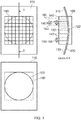
Figure 1 shows a schematic plan and elevational views of a thin walled component with attached lattice structure and projection according to an embodiment of the disclosure; -
Figure 2 shows a schematic perspective view of a portion of the lattice structure of the component ofFigure 1 showing the addition of a filler material; and -
Figure 3 shows a schematic perspective view of a gas engine casing according to a third aspect of the disclosure. - It is noted that the drawings may not be to scale. The drawings are intended to depict only typical aspects of the disclosure, and therefore should not be considered as limiting the scope of the disclosure. In the drawings, like numbering represents like elements between the drawings.
- Referring to
Figures 1 and2 , a thin walled component according to a first embodiment of the disclosure is designated generally by thereference numeral 110. - The thin
walled component 110 has afirst surface 120 and an oppositesecond surface 130. - A
first position 122 is identified on thefirst surface 120. Identification of thefirst position 122 is provided by the desired location of theprojection 100 that is to be attached to the thinwalled component 110. - A
second position 132 is identified on thesecond surface 130. Thesecond position 132 corresponds to thefirst position 122. In other words, thefirst position 122 and thesecond position 132 are coincident with one another on opposing surfaces 120,130 of the thin walled component. - A hollow thin
walled lattice structure 140 is built onto thesecond surface 130 of the thinwalled component 110, at thesecond position 132. In other words, thelattice structure 140 is centred on thesecond position 132. - The lattice structure is built using a liquid metal deposition process. Any suitable liquid metal deposition process may be used such as, for example, a blown powder technique or a wire feed technique. Such techniques are well known and will not be discussed further herein.
- The area of the
second surface 130 that is covered by thelattice structure 140 will be determined by the cross-sectional area of theprojection 100 that is to be built onto thefirst surface 120 of the thin walled component. Generally, thelattice structure 140 will cover a surface area that is larger than that of theprojection 100. - The size and shape of the area of the second surface that is covered by the
lattice structure 140 may be determined empirically, or may be determined by known computational analysis techniques. - The
lattice structure 140 comprises a plurality of individualelongate cells 142. Thecells 142 are built such that theiraxis 142 extends substantially normally from thesecond surface 130. Each of thecells 142 has awall thickness 144 of 0.8mm. - In the arrangement shown in
Figures 1 and2 , thecells 142 have a hexagonal cross-sectional shape (not shown). This enables theindividual cells 142 to most effectively fill the area covered by thelattice structure 140. - The
individual cells 142 are then filled with afiller material 170 in the form of a ceramic slurry. Thisfiller material 170 enhances the structural rigidity and the thermal insulative properties of thelattice structure 140. - Once the
lattice structure 140 has been built onto thesecond surface 130 of the thinwalled component 110, theprojection 100 can be built onto thefirst surface 120 of the thinwalled component 110. Theprojection 100 is also built using a liquid metal deposition process as outlined above for thelattice structure 140. - During the process of building the
projection 100 onto thefirst surface 120 of the thinwalled component 110, aheating fluid 160 is circulated over thelattice structure 140. The circulation of theheating fluid 160 across thelattice structure 140 offsets the thermal effect of the heat input from the liquid metal deposition process that is used to build theprojection 100. - In the embodiment shown in
Figures 1 and2 , theprojection 100 takes the form of aboss 100. -
Figure 3 shows a gasturbine engine casing 180 in the form of a thinwalled component 110 having an attachedprojection 100, with the projection having been attached by the method of the present disclosure. - The foregoing description of various aspects of the disclosure has been presented for purposes of illustration and description. It is not intended to be exhaustive or to limit the disclosure to the precise form disclosed, and obviously, many modifications and variations are possible. Such modifications and variations that may be apparent to a person of skill in the art are included within the scope of the disclosure as defined by the accompanying claims.
Claims (12)
- A method of attaching a projection (100) to a thin walled component (110), the thin walled component (110) having a first surface (120) and an opposite second surface (130), the method comprising the steps of:(i) providing a thin walled component (110);(ii) identifying a first position (122) on the first surface (120) of the thin walled component (110);(iii) building a hollow thin walled lattice structure (140) on the second surface (130) at a second position (132) using a liquid metal deposition process, the second position (132) corresponding to the first position (122); and(iv) building a projection (100) on the first surface (120) at the first position (122) using a liquid metal deposition process.
- The method as claimed in Claim 1, wherein the method comprises the further step of:(v) removing the hollow thin walled lattice structure (140) from the second surface (130).
- The method as claimed in Claim 1 or Claim 2, wherein the method comprises the further step of:(vi) heat treating the thin walled component (110) to relieve residual stresses resulting from the addition of the projection (100).
- The method as claimed in any one of Claims 1 to 3, wherein the hollow thin walled lattice structure (140) comprises a plurality of elongate cells (142), each of the cells (142) having an axis (143) that extends substantially normally to the second surface (130).
- The method as claimed in Claim 4, wherein each of the cells (142) has a wall thickness (144) of between 0.5mm and 1.0mm.
- The method as claimed in any one of Claims 1 to 5, wherein step (iv), comprises the concurrent step of:(iv-a) during the building of the projection (100), directing a cooling fluid (150) over the hollow thin walled lattice structure (140) to impinge upon the second surface (130) of the thin walled component (110).
- The method as claimed in any one of Claims 1 to 5, wherein step (iv), comprises the concurrent step of:(iv-a') during the building of the projection (100), directing a heating fluid (160) over the hollow thin walled lattice structure (140) to impinge upon the second surface (130) of the thin walled component (110).
- The method as claimed in any one of Claims 1 to 5, wherein step (iii) comprises the further step of:(iii-a) filling the hollow thin walled lattice structure (140) with a filler material (170).
- The method as claimed in Claim 8, wherein the filler material (170) is selected from the group consisting of ceramic slurry and ceramic foam.
- The method as claimed in any one of Claims 1 to 9, wherein the projection (100) is selected from the group consisting of boss, tube, flange, bracket and stub.
- An article comprising a thin walled component (110) having a projection (100) attached thereto by the method as claimed in any one of Claims 1 to 10.
- A gas turbine engine casing comprising a thin walled component (110) having a projection (100) attached thereto by the method as claimed in any one of Claims 1 to 10.
Applications Claiming Priority (1)
| Application Number | Priority Date | Filing Date | Title |
|---|---|---|---|
| GB1615164.9A GB2553531B (en) | 2016-09-07 | 2016-09-07 | A method of attaching a projection to a thin walled component |
Publications (1)
| Publication Number | Publication Date |
|---|---|
| EP3292945A1 true EP3292945A1 (en) | 2018-03-14 |
Family
ID=57140059
Family Applications (1)
| Application Number | Title | Priority Date | Filing Date |
|---|---|---|---|
| EP17189265.6A Withdrawn EP3292945A1 (en) | 2016-09-07 | 2017-09-04 | A method of attaching a projection to a thin walled component |
Country Status (3)
| Country | Link |
|---|---|
| US (1) | US10456835B2 (en) |
| EP (1) | EP3292945A1 (en) |
| GB (1) | GB2553531B (en) |
Cited By (1)
| Publication number | Priority date | Publication date | Assignee | Title |
|---|---|---|---|---|
| CN109848737A (en) * | 2019-03-12 | 2019-06-07 | 四川明日宇航工业有限责任公司 | A filling process suitable for mesh honeycomb parts |
Citations (10)
| Publication number | Priority date | Publication date | Assignee | Title |
|---|---|---|---|---|
| US4801070A (en) * | 1987-05-11 | 1989-01-31 | Rohr Industries, Inc. | Engine duct and case construction |
| WO2000044525A1 (en) * | 1999-01-29 | 2000-08-03 | Chromalloy Gas Turbine Corporation | Repair of turbine exhaust case |
| US20020020164A1 (en) * | 2000-07-26 | 2002-02-21 | Cleveland Bradley A. | Tubular body with deposited features and method of manufacture therefor |
| GB2442238A (en) * | 2006-09-29 | 2008-04-02 | Rolls Royce Plc | Sheet metal blank for gas turbine engine casing |
| US20080086882A1 (en) * | 2006-10-02 | 2008-04-17 | Andreas Eleftheriou | Annular gas turbine engine case and method of manufacturing |
| EP2472070A2 (en) * | 2010-12-30 | 2012-07-04 | Rolls-Royce Corporation | Methods of manufacturing a gas turbine engine case and corresponding case |
| DE102011108957A1 (en) * | 2011-07-29 | 2013-01-31 | Mtu Aero Engines Gmbh | A method for producing, repairing and / or replacing a housing, in particular an engine housing, and a corresponding housing |
| EP2884057A1 (en) * | 2013-12-13 | 2015-06-17 | Rolls-Royce Deutschland Ltd & Co KG | Joint assembly for gas turbine engine casings |
| US20160229127A1 (en) * | 2013-09-19 | 2016-08-11 | 3T Rpd Limited | Manufacturing method |
| EP3061561A1 (en) * | 2015-02-24 | 2016-08-31 | MTU Aero Engines GmbH | Method for producing a component and the component |
Family Cites Families (14)
| Publication number | Priority date | Publication date | Assignee | Title |
|---|---|---|---|---|
| US4152568A (en) * | 1975-08-08 | 1979-05-01 | Nippon Kokan Kabushiki Kaisha | Method of arc welding with reverse side cooling for obtaining highly tough large-diameter welded steel pipes |
| US4360141A (en) * | 1980-09-02 | 1982-11-23 | Kensrue Milo M | Holder for welding seam back-up tape |
| JP2002273579A (en) * | 2001-03-15 | 2002-09-25 | Hitachi Ltd | Method of joining iron-based material and its structure |
| KR100624425B1 (en) | 2004-06-17 | 2006-09-19 | 삼성전자주식회사 | An integrated multi-electrode for measuring a bio-signal, an integrated bio-signal measuring method and apparatus using an integrated multi-electrode, and a lead retrieval method using an integrated multi-electrode |
| FR2912674B1 (en) | 2007-02-20 | 2009-08-28 | Snecma Services Sa | METHOD FOR RECHARGING AN ALUMINUM ALLOY PIECE |
| TWI348975B (en) | 2007-09-29 | 2011-09-21 | Object moving apparatus | |
| FR2931714B1 (en) | 2008-05-30 | 2010-06-25 | Snecma | CONSTRUCTION OF A PART OF A METAL PIECE BY THE MIG PROCESS WITH CURRENT AND PULSED WIRE |
| FR2959434B1 (en) | 2010-04-30 | 2012-06-01 | Snecma | PROCESS FOR REPAIRING A TURBOMACHINE RETENTION CASE |
| DE102010051842A1 (en) * | 2010-11-18 | 2012-05-24 | Rolls-Royce Deutschland Ltd & Co Kg | Repair method of a sandwich-type component |
| DE102012201050B4 (en) * | 2012-01-25 | 2017-11-30 | MTU Aero Engines AG | Sealing arrangement, method and turbomachine |
| GB2502130A (en) * | 2012-05-17 | 2013-11-20 | Acergy France Sa | Improvements relating to pipe welding |
| US10913258B2 (en) * | 2015-02-02 | 2021-02-09 | Raytheon Technologies Corporation | Method and system for providing thermal support in an additive manufacturing process |
| US10480787B2 (en) * | 2015-03-26 | 2019-11-19 | United Technologies Corporation | Combustor wall cooling channel formed by additive manufacturing |
| CN204603602U (en) * | 2015-05-15 | 2015-09-02 | 重庆大学 | The inner water flowing copper billet forced cooling device of a kind of steel construction box column electroslag welding |
-
2016
- 2016-09-07 GB GB1615164.9A patent/GB2553531B/en active Active
-
2017
- 2017-09-04 EP EP17189265.6A patent/EP3292945A1/en not_active Withdrawn
- 2017-09-05 US US15/695,650 patent/US10456835B2/en not_active Expired - Fee Related
Patent Citations (10)
| Publication number | Priority date | Publication date | Assignee | Title |
|---|---|---|---|---|
| US4801070A (en) * | 1987-05-11 | 1989-01-31 | Rohr Industries, Inc. | Engine duct and case construction |
| WO2000044525A1 (en) * | 1999-01-29 | 2000-08-03 | Chromalloy Gas Turbine Corporation | Repair of turbine exhaust case |
| US20020020164A1 (en) * | 2000-07-26 | 2002-02-21 | Cleveland Bradley A. | Tubular body with deposited features and method of manufacture therefor |
| GB2442238A (en) * | 2006-09-29 | 2008-04-02 | Rolls Royce Plc | Sheet metal blank for gas turbine engine casing |
| US20080086882A1 (en) * | 2006-10-02 | 2008-04-17 | Andreas Eleftheriou | Annular gas turbine engine case and method of manufacturing |
| EP2472070A2 (en) * | 2010-12-30 | 2012-07-04 | Rolls-Royce Corporation | Methods of manufacturing a gas turbine engine case and corresponding case |
| DE102011108957A1 (en) * | 2011-07-29 | 2013-01-31 | Mtu Aero Engines Gmbh | A method for producing, repairing and / or replacing a housing, in particular an engine housing, and a corresponding housing |
| US20160229127A1 (en) * | 2013-09-19 | 2016-08-11 | 3T Rpd Limited | Manufacturing method |
| EP2884057A1 (en) * | 2013-12-13 | 2015-06-17 | Rolls-Royce Deutschland Ltd & Co KG | Joint assembly for gas turbine engine casings |
| EP3061561A1 (en) * | 2015-02-24 | 2016-08-31 | MTU Aero Engines GmbH | Method for producing a component and the component |
Cited By (1)
| Publication number | Priority date | Publication date | Assignee | Title |
|---|---|---|---|---|
| CN109848737A (en) * | 2019-03-12 | 2019-06-07 | 四川明日宇航工业有限责任公司 | A filling process suitable for mesh honeycomb parts |
Also Published As
| Publication number | Publication date |
|---|---|
| US20180065185A1 (en) | 2018-03-08 |
| US10456835B2 (en) | 2019-10-29 |
| GB2553531A (en) | 2018-03-14 |
| GB2553531B (en) | 2019-02-06 |
| GB201615164D0 (en) | 2016-10-19 |
Similar Documents
| Publication | Publication Date | Title |
|---|---|---|
| CN109530694B (en) | Selective laser melting forming method for TC4 titanium alloy multi-channel valve body | |
| DK2814649T3 (en) | DIRECT FORMS FOR WINDERS FOR WIND MILLS, MANUFACTURING PROCEDURE AND APPLICATION OF THE FORM | |
| US8684069B2 (en) | Process for manufacturing a metal part by selectively melting a powder | |
| RU2631218C2 (en) | Turbomachine blade reinforcement metal element manufacturing method | |
| CN103429780B (en) | Method for producing a metal component such as a turbomachine blade reinforcement | |
| CN114131048B (en) | Design method and device for forming annular part by selective laser melting | |
| US20150075746A1 (en) | Method of Casting a Component Having Interior Passageways | |
| EP3366885B1 (en) | Article and method of forming an article | |
| US20030136547A1 (en) | Heat transfer surface with a microstructure of projections galvanized onto it | |
| EP3168419B1 (en) | Article and method of forming an article | |
| WO2018005889A2 (en) | Methods and thin walled reinforced structures for additive manufacturing | |
| US10323532B2 (en) | Flow discourager and method of making same | |
| US11091266B2 (en) | Conformable tank fabricated using additive manufacturing | |
| US10456835B2 (en) | Method of attaching a projection to a thin walled component | |
| EP3085472B1 (en) | Method of manufacturing a turbine blisk through hot isostatic pressing using a metal core | |
| EP3055087B1 (en) | Method of forming a complexly curved metallic sandwich panel | |
| CN103476544B (en) | The method making metal parts | |
| EP3628475A3 (en) | System and method for manufacturing composite structures | |
| US20220282391A1 (en) | Additive heat exchanger and method of forming | |
| US20240300131A1 (en) | Method for segmenting a part comprising a plurality of thin elements separated by interstices | |
| CN112236252B (en) | Powder removal of floating structures | |
| EP3231601A1 (en) | Light weight housing for internal component and method of making | |
| CN113441586A (en) | Method for bending vortex-shaped induction coil and vortex-shaped induction coil | |
| CN109592009A (en) | A kind of aircraft abdomeinal fin structure | |
| US10654230B2 (en) | Methods of forming a cored composite laminate |
Legal Events
| Date | Code | Title | Description |
|---|---|---|---|
| PUAI | Public reference made under article 153(3) epc to a published international application that has entered the european phase |
Free format text: ORIGINAL CODE: 0009012 |
|
| STAA | Information on the status of an ep patent application or granted ep patent |
Free format text: STATUS: THE APPLICATION HAS BEEN PUBLISHED |
|
| AK | Designated contracting states |
Kind code of ref document: A1 Designated state(s): AL AT BE BG CH CY CZ DE DK EE ES FI FR GB GR HR HU IE IS IT LI LT LU LV MC MK MT NL NO PL PT RO RS SE SI SK SM TR |
|
| AX | Request for extension of the european patent |
Extension state: BA ME |
|
| STAA | Information on the status of an ep patent application or granted ep patent |
Free format text: STATUS: REQUEST FOR EXAMINATION WAS MADE |
|
| 17P | Request for examination filed |
Effective date: 20180910 |
|
| RBV | Designated contracting states (corrected) |
Designated state(s): AL AT BE BG CH CY CZ DE DK EE ES FI FR GB GR HR HU IE IS IT LI LT LU LV MC MK MT NL NO PL PT RO RS SE SI SK SM TR |
|
| RAP1 | Party data changed (applicant data changed or rights of an application transferred) |
Owner name: ROLLS-ROYCE PLC Owner name: TWI LIMITED |
|
| RIC1 | Information provided on ipc code assigned before grant |
Ipc: F01D 25/24 20060101ALI20201007BHEP Ipc: B22F 7/08 20060101ALN20201007BHEP Ipc: B22F 3/115 20060101ALI20201007BHEP Ipc: B23P 15/00 20060101AFI20201007BHEP |
|
| STAA | Information on the status of an ep patent application or granted ep patent |
Free format text: STATUS: THE APPLICATION IS DEEMED TO BE WITHDRAWN |
|
| 18D | Application deemed to be withdrawn |
Effective date: 20210501 |