EP3292844A1 - Prosthesis deployment system - Google Patents
Prosthesis deployment system Download PDFInfo
- Publication number
- EP3292844A1 EP3292844A1 EP17275140.6A EP17275140A EP3292844A1 EP 3292844 A1 EP3292844 A1 EP 3292844A1 EP 17275140 A EP17275140 A EP 17275140A EP 3292844 A1 EP3292844 A1 EP 3292844A1
- Authority
- EP
- European Patent Office
- Prior art keywords
- segment
- positioning member
- tip
- tubular segment
- prosthesis
- Prior art date
- Legal status (The legal status is an assumption and is not a legal conclusion. Google has not performed a legal analysis and makes no representation as to the accuracy of the status listed.)
- Granted
Links
- 238000000034 method Methods 0.000 description 23
- 230000007246 mechanism Effects 0.000 description 17
- 239000000463 material Substances 0.000 description 15
- 230000008878 coupling Effects 0.000 description 9
- 238000010168 coupling process Methods 0.000 description 9
- 238000005859 coupling reaction Methods 0.000 description 9
- 230000036961 partial effect Effects 0.000 description 8
- 239000000853 adhesive Substances 0.000 description 7
- 230000001070 adhesive effect Effects 0.000 description 7
- 230000014759 maintenance of location Effects 0.000 description 6
- 229910052751 metal Inorganic materials 0.000 description 6
- 239000002184 metal Substances 0.000 description 6
- 150000002739 metals Chemical class 0.000 description 6
- 230000002441 reversible effect Effects 0.000 description 6
- 238000003466 welding Methods 0.000 description 6
- 230000000670 limiting effect Effects 0.000 description 5
- 239000004033 plastic Substances 0.000 description 5
- 229920003023 plastic Polymers 0.000 description 5
- 229910045601 alloy Inorganic materials 0.000 description 4
- 239000000956 alloy Substances 0.000 description 4
- 229920000642 polymer Polymers 0.000 description 4
- 229920001343 polytetrafluoroethylene Polymers 0.000 description 4
- 239000004810 polytetrafluoroethylene Substances 0.000 description 4
- 230000009471 action Effects 0.000 description 3
- 238000013459 approach Methods 0.000 description 3
- 230000008901 benefit Effects 0.000 description 3
- 239000012530 fluid Substances 0.000 description 3
- 230000002401 inhibitory effect Effects 0.000 description 3
- -1 polyethylene terephthalate Polymers 0.000 description 3
- 230000002829 reductive effect Effects 0.000 description 3
- 239000004696 Poly ether ether ketone Substances 0.000 description 2
- 210000003484 anatomy Anatomy 0.000 description 2
- 238000004873 anchoring Methods 0.000 description 2
- 239000000560 biocompatible material Substances 0.000 description 2
- 239000012620 biological material Substances 0.000 description 2
- 230000001419 dependent effect Effects 0.000 description 2
- 239000004744 fabric Substances 0.000 description 2
- 238000003384 imaging method Methods 0.000 description 2
- 238000012986 modification Methods 0.000 description 2
- 230000004048 modification Effects 0.000 description 2
- HLXZNVUGXRDIFK-UHFFFAOYSA-N nickel titanium Chemical compound [Ti].[Ti].[Ti].[Ti].[Ti].[Ti].[Ti].[Ti].[Ti].[Ti].[Ti].[Ni].[Ni].[Ni].[Ni].[Ni].[Ni].[Ni].[Ni].[Ni].[Ni].[Ni].[Ni].[Ni].[Ni] HLXZNVUGXRDIFK-UHFFFAOYSA-N 0.000 description 2
- 229910001000 nickel titanium Inorganic materials 0.000 description 2
- 229920000728 polyester Polymers 0.000 description 2
- 229920002530 polyetherether ketone Polymers 0.000 description 2
- 229920000139 polyethylene terephthalate Polymers 0.000 description 2
- 239000005020 polyethylene terephthalate Substances 0.000 description 2
- 229920002635 polyurethane Polymers 0.000 description 2
- 239000004814 polyurethane Substances 0.000 description 2
- 230000008569 process Effects 0.000 description 2
- 230000008439 repair process Effects 0.000 description 2
- 239000010935 stainless steel Substances 0.000 description 2
- 229910001220 stainless steel Inorganic materials 0.000 description 2
- 102000010834 Extracellular Matrix Proteins Human genes 0.000 description 1
- 108010037362 Extracellular Matrix Proteins Proteins 0.000 description 1
- 201000008982 Thoracic Aortic Aneurysm Diseases 0.000 description 1
- 238000004026 adhesive bonding Methods 0.000 description 1
- 208000007474 aortic aneurysm Diseases 0.000 description 1
- 230000000712 assembly Effects 0.000 description 1
- 238000000429 assembly Methods 0.000 description 1
- 238000000576 coating method Methods 0.000 description 1
- 230000001010 compromised effect Effects 0.000 description 1
- 238000006073 displacement reaction Methods 0.000 description 1
- 230000007717 exclusion Effects 0.000 description 1
- 210000002744 extracellular matrix Anatomy 0.000 description 1
- 208000003457 familial thoracic 1 aortic aneurysm Diseases 0.000 description 1
- 210000001105 femoral artery Anatomy 0.000 description 1
- 238000002594 fluoroscopy Methods 0.000 description 1
- 238000011010 flushing procedure Methods 0.000 description 1
- 238000002513 implantation Methods 0.000 description 1
- 238000002347 injection Methods 0.000 description 1
- 239000007924 injection Substances 0.000 description 1
- 238000003780 insertion Methods 0.000 description 1
- 230000037431 insertion Effects 0.000 description 1
- 230000003993 interaction Effects 0.000 description 1
- 230000002452 interceptive effect Effects 0.000 description 1
- 239000003550 marker Substances 0.000 description 1
- 239000011159 matrix material Substances 0.000 description 1
- 210000000056 organ Anatomy 0.000 description 1
- 230000000717 retained effect Effects 0.000 description 1
- 229920002994 synthetic fiber Polymers 0.000 description 1
- 210000001519 tissue Anatomy 0.000 description 1
- 230000007704 transition Effects 0.000 description 1
- 238000011282 treatment Methods 0.000 description 1
- 210000005166 vasculature Anatomy 0.000 description 1
- 125000000391 vinyl group Chemical group [H]C([*])=C([H])[H] 0.000 description 1
- 229920002554 vinyl polymer Polymers 0.000 description 1
- 238000012800 visualization Methods 0.000 description 1
Images


Classifications
-
- A—HUMAN NECESSITIES
- A61—MEDICAL OR VETERINARY SCIENCE; HYGIENE
- A61F—FILTERS IMPLANTABLE INTO BLOOD VESSELS; PROSTHESES; DEVICES PROVIDING PATENCY TO, OR PREVENTING COLLAPSING OF, TUBULAR STRUCTURES OF THE BODY, e.g. STENTS; ORTHOPAEDIC, NURSING OR CONTRACEPTIVE DEVICES; FOMENTATION; TREATMENT OR PROTECTION OF EYES OR EARS; BANDAGES, DRESSINGS OR ABSORBENT PADS; FIRST-AID KITS
- A61F2/00—Filters implantable into blood vessels; Prostheses, i.e. artificial substitutes or replacements for parts of the body; Appliances for connecting them with the body; Devices providing patency to, or preventing collapsing of, tubular structures of the body, e.g. stents
- A61F2/95—Instruments specially adapted for placement or removal of stents or stent-grafts
- A61F2/962—Instruments specially adapted for placement or removal of stents or stent-grafts having an outer sleeve
- A61F2/966—Instruments specially adapted for placement or removal of stents or stent-grafts having an outer sleeve with relative longitudinal movement between outer sleeve and prosthesis, e.g. using a push rod
-
- A—HUMAN NECESSITIES
- A61—MEDICAL OR VETERINARY SCIENCE; HYGIENE
- A61F—FILTERS IMPLANTABLE INTO BLOOD VESSELS; PROSTHESES; DEVICES PROVIDING PATENCY TO, OR PREVENTING COLLAPSING OF, TUBULAR STRUCTURES OF THE BODY, e.g. STENTS; ORTHOPAEDIC, NURSING OR CONTRACEPTIVE DEVICES; FOMENTATION; TREATMENT OR PROTECTION OF EYES OR EARS; BANDAGES, DRESSINGS OR ABSORBENT PADS; FIRST-AID KITS
- A61F2/00—Filters implantable into blood vessels; Prostheses, i.e. artificial substitutes or replacements for parts of the body; Appliances for connecting them with the body; Devices providing patency to, or preventing collapsing of, tubular structures of the body, e.g. stents
- A61F2/02—Prostheses implantable into the body
- A61F2/04—Hollow or tubular parts of organs, e.g. bladders, tracheae, bronchi or bile ducts
- A61F2/06—Blood vessels
- A61F2/07—Stent-grafts
-
- A—HUMAN NECESSITIES
- A61—MEDICAL OR VETERINARY SCIENCE; HYGIENE
- A61F—FILTERS IMPLANTABLE INTO BLOOD VESSELS; PROSTHESES; DEVICES PROVIDING PATENCY TO, OR PREVENTING COLLAPSING OF, TUBULAR STRUCTURES OF THE BODY, e.g. STENTS; ORTHOPAEDIC, NURSING OR CONTRACEPTIVE DEVICES; FOMENTATION; TREATMENT OR PROTECTION OF EYES OR EARS; BANDAGES, DRESSINGS OR ABSORBENT PADS; FIRST-AID KITS
- A61F2/00—Filters implantable into blood vessels; Prostheses, i.e. artificial substitutes or replacements for parts of the body; Appliances for connecting them with the body; Devices providing patency to, or preventing collapsing of, tubular structures of the body, e.g. stents
- A61F2/82—Devices providing patency to, or preventing collapsing of, tubular structures of the body, e.g. stents
- A61F2/86—Stents in a form characterised by the wire-like elements; Stents in the form characterised by a net-like or mesh-like structure
- A61F2/90—Stents in a form characterised by the wire-like elements; Stents in the form characterised by a net-like or mesh-like structure characterised by a net-like or mesh-like structure
- A61F2/91—Stents in a form characterised by the wire-like elements; Stents in the form characterised by a net-like or mesh-like structure characterised by a net-like or mesh-like structure made from perforated sheet material or tubes, e.g. perforated by laser cuts or etched holes
- A61F2/915—Stents in a form characterised by the wire-like elements; Stents in the form characterised by a net-like or mesh-like structure characterised by a net-like or mesh-like structure made from perforated sheet material or tubes, e.g. perforated by laser cuts or etched holes with bands having a meander structure, adjacent bands being connected to each other
-
- A—HUMAN NECESSITIES
- A61—MEDICAL OR VETERINARY SCIENCE; HYGIENE
- A61F—FILTERS IMPLANTABLE INTO BLOOD VESSELS; PROSTHESES; DEVICES PROVIDING PATENCY TO, OR PREVENTING COLLAPSING OF, TUBULAR STRUCTURES OF THE BODY, e.g. STENTS; ORTHOPAEDIC, NURSING OR CONTRACEPTIVE DEVICES; FOMENTATION; TREATMENT OR PROTECTION OF EYES OR EARS; BANDAGES, DRESSINGS OR ABSORBENT PADS; FIRST-AID KITS
- A61F2/00—Filters implantable into blood vessels; Prostheses, i.e. artificial substitutes or replacements for parts of the body; Appliances for connecting them with the body; Devices providing patency to, or preventing collapsing of, tubular structures of the body, e.g. stents
- A61F2/95—Instruments specially adapted for placement or removal of stents or stent-grafts
- A61F2/9517—Instruments specially adapted for placement or removal of stents or stent-grafts handle assemblies therefor
-
- A—HUMAN NECESSITIES
- A61—MEDICAL OR VETERINARY SCIENCE; HYGIENE
- A61F—FILTERS IMPLANTABLE INTO BLOOD VESSELS; PROSTHESES; DEVICES PROVIDING PATENCY TO, OR PREVENTING COLLAPSING OF, TUBULAR STRUCTURES OF THE BODY, e.g. STENTS; ORTHOPAEDIC, NURSING OR CONTRACEPTIVE DEVICES; FOMENTATION; TREATMENT OR PROTECTION OF EYES OR EARS; BANDAGES, DRESSINGS OR ABSORBENT PADS; FIRST-AID KITS
- A61F2/00—Filters implantable into blood vessels; Prostheses, i.e. artificial substitutes or replacements for parts of the body; Appliances for connecting them with the body; Devices providing patency to, or preventing collapsing of, tubular structures of the body, e.g. stents
- A61F2/95—Instruments specially adapted for placement or removal of stents or stent-grafts
- A61F2002/9505—Instruments specially adapted for placement or removal of stents or stent-grafts having retaining means other than an outer sleeve, e.g. male-female connector between stent and instrument
- A61F2002/9511—Instruments specially adapted for placement or removal of stents or stent-grafts having retaining means other than an outer sleeve, e.g. male-female connector between stent and instrument the retaining means being filaments or wires
-
- A—HUMAN NECESSITIES
- A61—MEDICAL OR VETERINARY SCIENCE; HYGIENE
- A61F—FILTERS IMPLANTABLE INTO BLOOD VESSELS; PROSTHESES; DEVICES PROVIDING PATENCY TO, OR PREVENTING COLLAPSING OF, TUBULAR STRUCTURES OF THE BODY, e.g. STENTS; ORTHOPAEDIC, NURSING OR CONTRACEPTIVE DEVICES; FOMENTATION; TREATMENT OR PROTECTION OF EYES OR EARS; BANDAGES, DRESSINGS OR ABSORBENT PADS; FIRST-AID KITS
- A61F2/00—Filters implantable into blood vessels; Prostheses, i.e. artificial substitutes or replacements for parts of the body; Appliances for connecting them with the body; Devices providing patency to, or preventing collapsing of, tubular structures of the body, e.g. stents
- A61F2/95—Instruments specially adapted for placement or removal of stents or stent-grafts
- A61F2/962—Instruments specially adapted for placement or removal of stents or stent-grafts having an outer sleeve
- A61F2/966—Instruments specially adapted for placement or removal of stents or stent-grafts having an outer sleeve with relative longitudinal movement between outer sleeve and prosthesis, e.g. using a push rod
- A61F2002/9665—Instruments specially adapted for placement or removal of stents or stent-grafts having an outer sleeve with relative longitudinal movement between outer sleeve and prosthesis, e.g. using a push rod with additional retaining means
-
- A—HUMAN NECESSITIES
- A61—MEDICAL OR VETERINARY SCIENCE; HYGIENE
- A61F—FILTERS IMPLANTABLE INTO BLOOD VESSELS; PROSTHESES; DEVICES PROVIDING PATENCY TO, OR PREVENTING COLLAPSING OF, TUBULAR STRUCTURES OF THE BODY, e.g. STENTS; ORTHOPAEDIC, NURSING OR CONTRACEPTIVE DEVICES; FOMENTATION; TREATMENT OR PROTECTION OF EYES OR EARS; BANDAGES, DRESSINGS OR ABSORBENT PADS; FIRST-AID KITS
- A61F2210/00—Particular material properties of prostheses classified in groups A61F2/00 - A61F2/26 or A61F2/82 or A61F9/00 or A61F11/00 or subgroups thereof
- A61F2210/0014—Particular material properties of prostheses classified in groups A61F2/00 - A61F2/26 or A61F2/82 or A61F9/00 or A61F11/00 or subgroups thereof using shape memory or superelastic materials, e.g. nitinol
-
- A—HUMAN NECESSITIES
- A61—MEDICAL OR VETERINARY SCIENCE; HYGIENE
- A61M—DEVICES FOR INTRODUCING MEDIA INTO, OR ONTO, THE BODY; DEVICES FOR TRANSDUCING BODY MEDIA OR FOR TAKING MEDIA FROM THE BODY; DEVICES FOR PRODUCING OR ENDING SLEEP OR STUPOR
- A61M25/00—Catheters; Hollow probes
- A61M25/0067—Catheters; Hollow probes characterised by the distal end, e.g. tips
- A61M25/0074—Dynamic characteristics of the catheter tip, e.g. openable, closable, expandable or deformable
Landscapes
- Health & Medical Sciences (AREA)
- Engineering & Computer Science (AREA)
- Biomedical Technology (AREA)
- Cardiology (AREA)
- Oral & Maxillofacial Surgery (AREA)
- Transplantation (AREA)
- Heart & Thoracic Surgery (AREA)
- Vascular Medicine (AREA)
- Life Sciences & Earth Sciences (AREA)
- Animal Behavior & Ethology (AREA)
- General Health & Medical Sciences (AREA)
- Public Health (AREA)
- Veterinary Medicine (AREA)
- Media Introduction/Drainage Providing Device (AREA)
Abstract
Description
- This application claims the benefit of the filing date under 35 U.S.C. § 119(e) of Provisional
U.S. Patent Application Serial No. 62/385,593, filed September 9, 2016 - The present disclosure relates generally to medical devices, and more particularly, to a system and method for placement and deployment of a prosthesis in a vessel lumen.
- The use of delivery devices or introducers employing catheters has long been known for a variety of medical procedures, including procedures for establishing, re-establishing or maintaining passages, cavities or lumens in vessels, organs or ducts in human and veterinary patients, occlusion of such vessels, delivering medical treatments, and other interventions. For these procedures, it has also long been known to deliver an implantable prosthesis by means of a catheter, often intraluminally. For example, a stent, stent-graft, vena cava filter, occlusion device, or other prostheses can be delivered intraluminally from the femoral artery, via a transapical approach and/or using other acceptable delivery locations and methods for deployment of the prosthesis.
- For procedures in which a prosthesis or other medical device is implanted into a patient, the prosthesis to be implanted is normally held on a carrier catheter or cannula of the introducer in a compressed state. The prosthesis is positioned between the walls of the introducer and a sheath over the prosthesis. The prosthesis is then released from the cannula so as to expand to its normal operating state, prior to withdrawal of the cannula from the patient. In many devices, the steps to carry out the implantation can occur, for example, first by retracting a retractable sheath to expand or partially expand the prosthesis, and then performing further steps to, for example, release one or both ends of the prosthesis, deploy an anchoring stent, or the like. Other steps may include pushing a tubular shell of a dilator tip forward relative to a reverse tapered body in order to partially expand a top portion, such as a bare top stent, of the prosthesis. Often these steps require the physician operator to manipulate multiple handles and pin vises to lock and unlock relevant components. The prosthesis which is to be implanted within a patient's vessels by the delivery device may vary depending on various factors including the procedure being performed and the portion of the vessels being treated. The delivery device described herein can be configured to deploy a wide range of different prostheses including, but not limited to cuffs, single lumen tubular stent grafts, bifurcated AAA stent grafts, branched or fenestrated stent grafts and combinations thereof. In addition to facilitating the delivery of a wide range of prostheses, the delivery device can be used for a variety of delivery approaches to be utilized, including but not limited to transapical or femoral approaches.
- According to an aspect of the present invention, a prosthesis deployment system is provided having a positioning member in a deployed configuration for inhibiting a tip body segment from moving relative to an enlarged body. The tip body segment is coupled to an end of an inner cannula. A tubular segment extends away from the tip body segment, defining a lumen between an internal axial end of the tip body segment and an edge of the tubular segment. The enlarged body is slidably disposed within the lumen of the tubular segment. The enlarged body is coupled to an end of a concentric cannula that is coaxially disposed about the inner cannula. The positioning member is at least partially disposed within the lumen of the tubular segment. The positioning member has a first member end coupled to one of the enlarged body or the tip body segment. The positioning member is deployable when the enlarged body is at a position corresponding to the edge of the tubular segment.
- According to another aspect of the present invention, a delivery device includes a flareable wire member having a member end coupled to an enlarged body member and extending toward the tip body segment. The system includes a tip cannula and a tip body segment coupled to an end of the tip cannula. A tubular segment is extended away from the tip body segment. The tubular segment defines a lumen extending through an end opening of the tubular segment and terminating at an internal end of the tip body segment. The device further includes an enlarged body cannula slidably disposed about the tip cannula. The enlarged body member is coupled to an end of the enlarged body cannula, and slidably disposed along the lumen of the tubular segment. The flareable wire member is radially movable about the member end between a nondeployed configuration and a deployed configuration. In its nondeployed configuration, at least a portion of the flareable wire member is received in a port formed in the tip body segment. In its deployed configuration, the flareable wire member is at least partially withdrawn from the port and moved radially within the tubular segment.
- Preferably the flareable wire member moves radially outward under a spring force to its deployed configuration.
- Preferably the flareable wire member includes an undulation.
- In an embodiment, a method of deployment of a prosthesis with a delivery device is provided. The method includes providing the delivery device that includes a tip assembly coupled to an end of an inner cannula. The tip assembly includes a tip body segment and a tubular segment extending from the tip body segment. The tubular segment defines a lumen extending through an end opening of the tubular segment and terminating at an internal axial end of the tip body segment. The lumen of the tubular segment receives a portion of a prosthesis in a radially compressed configuration. The system further includes an enlarged body coupled to a concentric cannula slidably disposed about the inner cannula, and a positioning member at least partially disposed within the tubular segment of the tip assembly at a nondeployed configuration. A step of the method includes moving relatively the enlarged body and the tip assembly by a distance for removing the tubular segment of the tip assembly from around a portion of the prosthesis to allow the portion of the prosthesis to radially expand. Another step of the method includes radially moving the positioning member within the tubular segment from its nondeployed configuration to a deployed configuration, the positioning member in its deployed configuration inhibiting the tip assembly from moving relatively closer to the enlarged body after the relative movement between the enlarged body and the tip assembly by the distance.
- Thus the invention also provides a method of deployment of a prosthesis with a delivery device, including: providing a delivery device including a tip assembly coupled to an end of an inner cannula, the tip assembly including a tip body segment and a tubular segment extending from the tip body segment, the tubular segment defining a lumen extending through an end opening of the tubular segment and terminating at an internal axial end of the tip body segment, the lumen of the tubular segment receiving a portion of a prosthesis in a radially compressed configuration, an enlarged body coupled to a concentric cannula slidably disposed about the inner cannula, and a positioning member at least partially disposed within the tubular segment of the tip assembly at a nondeployed configuration; moving relatively the enlarged body and the tip assembly by a distance for removing the tubular segment of the tip assembly from around a portion of the prosthesis to allow the portion of the prosthesis to radially expand; radially moving the positioning member within the tubular segment from its nondeployed configuration to a deployed configuration, the positioning member in its deployed configuration inhibiting the tip assembly from moving relatively closer to the enlarged body after relative movement between the enlarged body and the tip assembly by the distance.
- In a preferred method the positioning member includes a member end coupled to the enlarged body and a free end extending toward the tip body segment, wherein when the positioning member is in its nondeployed configuration at least a portion of the positioning member is received in a port formed in the internal axial end of the tip body segment, and during the relatively moving step the positioning member is being withdrawn from the opening, and wherein when the positioning member in its deployed configuration the free end engages with the internal axial end of the tip body segment.
- Other systems, methods, features and advantages of the invention will be, or will become, apparent to one with skill in the art upon examination of the following figures and detailed description. It is intended that all such additional systems, methods, features and advantages be within the scope of the invention, and be encompassed by the following claims.
- The invention can be better understood with reference to the following drawings and description. The components in the figures are not necessarily to scale, emphasis instead being placed upon illustrating the principles of the invention. Moreover, in the figures, like referenced numerals designate corresponding parts throughout the different views.
-
FIG. 1 is a perspective view of an example of a prosthesis deployment system having a prosthesis in a radially compressed configuration. -
FIG. 2 is a side view of a proximal end of the prosthesis deployment system ofFIG. 1 , with an outer sheath in an extended position, a prosthesis in a radially compressed configuration, and an example of a positioning member in a nondeployed configuration. -
FIG. 3 is a side view of a proximal end of the prosthesis deployment system ofFIG. 1 , with an outer sheath in an extended position, a tip assembly being moved proximally away from a prosthesis with a portion thereof being radially expanded, and an example of a positioning member moving from a nondeployed configuration to a deployed configuration. -
FIG. 4 is a side view of a proximal end of the prosthesis deployment system ofFIG. 1 , with an outer sheath partially retracted, a tip assembly moved fully away from a prosthesis with a portion thereof being radially expanded, and an example of a positioning member in a deployed configuration. -
FIG. 5 is a side view of a proximal end of the prosthesis deployment system ofFIG. 1 , with an outer sheath being further retracted from a prosthesis with a portion thereof being radially expanded, and an example of a positioning member in a deployed configuration. -
FIG. 6 is a side view of a proximal end of the prosthesis deployment system ofFIG. 1 , with an outer sheath fully retracted from a prosthesis, allowing the prosthesis to fully expand to a radially expanded configuration, and an example of a positioning member in a deployed configuration. -
FIG. 7 is a side view of a proximal end of the prosthesis deployment system ofFIG. 1 , with a delivery device being withdrawn distally from a lumen of a prosthesis in a radially expanded configuration. -
FIG. 8 is a cross-sectional view of a proximal end of the prosthesis deployment system ofFIG. 1 , with an outer sheath in an extended position, a prosthesis in a radially compressed configuration, and an example of a positioning member in a nondeployed configuration. -
FIG. 9 is a cross-sectional view of a proximal end of the prosthesis deployment system ofFIG. 1 , with an outer sheath partially retracted distally and a tip assembly moved fully away from a prosthesis with a portion thereof being radially expanded, and an example of a positioning member in a deployed configuration. -
FIG. 10 is a cross-sectional view of a proximal end of the prosthesis deployment system ofFIG. 1 , with a delivery device being withdrawn distally from a lumen of a prosthesis in a radially expanded configuration. -
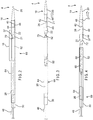
FIG. 11A is a partial view of an enlarged body coupled to a concentric cannula, having an example of a positioning member having a series of undulations. -
FIG. 11B is a partial view of an enlarged body coupled to a concentric cannula, having an example of a pair of positioning members. -
FIG. 11C is a partial view of an enlarged body coupled to a concentric cannula, having an example of a pair of positioning members extending from a same location. -
FIG. 12A is a partial cross-sectional view of an example of a tubular segment including a protruding tab for contacting an end of a positioning member. -
FIG. 12B is a partial cross-sectional view of an example of a tubular segment including a groove for contacting an end of a positioning member. -
FIG. 13 is a cross-sectional view of a tip assembly and an example of a positioning member extending from the tip assembly. -
FIG. 14 is a perspective view of an example of an enlarged body coupled to a concentric cannula, having a receiving channel. - In the present application, the term "proximal" when referring to a delivery device refers to a direction that is farthest away from an operator using a delivery device, while the term "distal" refers to a direction that is generally closest to the operator using the delivery device. The proximal and distal ends of a delivery device may also be referred to as an introduction end of the delivery device and an operator end of the delivery device, respectively. The term "operator end" of the delivery device is that portion of the device that is intended to remain outside of a patient during a procedure. The term "introduction end" of the delivery device, which is opposite to the operator end, is that portion of the device that is intended to be inserted within a patient during a procedure. When referring to the prosthesis itself relative to the delivery device, the proximal end of the prosthesis is that part of the prosthesis closest in proximity to the introduction end of the delivery device and the distal end of the prosthesis is that end that is closest in proximity to the operator end of the delivery device. When referring to the prosthesis relative to placement in the human body of the patient, the ends of the various devices and parts of devices may be referred to as the inflow end (that end that receives fluid first, and the outflow end (that end from which the fluid exits).
- Referring initially to
FIG. 1 , a prosthesis deployment system 1 is provided to include adelivery device 2 and aprosthesis 52 loaded in thedelivery device 2. An example of thedelivery device 2 includes a proximal orintroduction end 4 and adistal operator end 6. A handle assembly 8 is located adjacent thedistal operator end 6 of thedevice 2. In one example, the handle assembly 8 may include a first ormain handle 10. This may be the front most handle that is closest in proximity to theintroduction end 4 of thedelivery device 2. The handle assembly 8 may further include additional handles, such as, for example, a second orintermediate handle 12 and a third orrearmost handle 14 that is closest in proximity to thedistal operator end 6. Themain handle 10 can be fixed relative to thedelivery device 2. In one example, themain handle 10 may also be fixed relative to theintermediate handle 12 and/or to therearmost handle 14, with theintermediate handle 12 and therearmost handle 14 being separately and independently rotatable relative to themain handle 10 and to each other. Further details of examples of a handle assembly that can be used to manipulate the prosthesis deployment are described herein and inU.S. Provisional Application No. 62/212,767 filed on September 01, 2015 - As shown in
FIG. 1 , theintroduction end 4 of thedelivery device 2 includes aretention region 16 upon which theprosthesis 52 can be releasably coupled and a tip assembly ornose cone dilator 18. Thetip assembly 18 may include a proximaltip body segment 20 and a tubular segment 21 (also known as a top cap and shown inFIGS. 2-7 ) extending away from thetip body segment 20 toward theoperator end 6 of thedelivery device 2. - As shown further in
FIGS. 8-10 , thetip body segment 20 can be shaped to include a forwardproximal taper 19 and include aninner lumen 20a extending therethrough to receive a guide wire 28 (shownFIG. 8 ). Further inFIG. 9 , aninternal wall 21 b of thetubular segment 21 defines asegment lumen 21 a. The segment lumen 21 a may extend between anend opening 23 defined at the distal end of thetubular segment 21 and terminating at an internalaxial end 25 at the distal end of thetip body segment 20. - Also shown in
FIGS. 8-10 , a separate distalenlarged body 22 may be disposed adjacent to thetip assembly 18. Theenlarged body 22 may be shaped to have a reversedistal taper 72 and include aninner lumen 22a formed axially therein. Thetip assembly 18 may present a smooth tapered surface to facilitate entry into and movement through a body vessel and facilitate deployment of theprostheses 52, as will be described in further detail below.Tip assembly 18 may include radiopaque material or be equipped with a radiopaque marker (not shown) to facilitate visualization of thetip assembly 18 in use provided by desired imaging modality (i.e., by fluoroscopy, MRI, 3D or other imaging techniques). - As shown in
FIG. 1 , aninner cannula 26 extends the longitudinal length of thedelivery device 2, from thedistal operator end 6 of thedevice 2 to thetip body segment 20 at theintroduction end 4 of thedevice 2. Apin vise 24 is shown provided along the handle assembly 8 and used to selectively lock theinner cannula 26, as can be appreciated by those of ordinary skill. Theinner cannula 26 can be connected at one end (its distal end) within the handle assembly 8 in a manner to facilitate pushing the inner cannula forward or proximally and pulling the inner cannula backwardly relative to thedelivery device 2, as described further herein. At its other end (its proximal end), theinner cannula 26 may be moveably received within theinner lumen 22a of theenlarged body 22, as shown inFIGS. 8-10 , and can be fixedly attached within theinner lumen 20a of thetip body segment 20 to define another aspect of thetip assembly 18. More particularly, theinner cannula 26 extends through theinner lumen 22a of theenlarged body 22, which can be configured to allow theinner cannula 26 to move or slide longitudinally therein. - The
inner cannula 26 also extends through theinner lumen 20a of thetip body segment 20, and can be attached or coupled to thetip body segment 20 by various means, including adhesives, welding, and/or other suitable attachment mechanism. In one example, theinner cannula 26 can be attached to thetip body segment 20 by an overmolding process and a gluing process. As a result, pushing movement of theinner cannula 26 in a forward (proximal) direction simultaneously causes forward (proximal) longitudinal movement of theinner cannula 26 as well as forward (proximal) movement of thetip body segment 20 of thetip assembly 18. - In an example, the
inner cannula 26, thetip body segment 20, and thetubular segment 21 may define an integral unit of thetip assembly 18, moving together when force is applied to either one. Theinner cannula 26 includes aninner lumen 26a to accommodate theguide wire 28, as shown inFIG. 8 , for tracking thedelivery device 2 to a desired position within a patient's vasculature and which can also be used for flushing or injection of fluids. Theinner cannula 26 can be made of a variety of suitable materials that are stiff, yet flexible enough to allow theinner cannula 26 to conform to the tortious anatomy of a patient during use, and can be either straight or have a curve imparted to a portion of it. - With reference to
FIGS. 2-10 , apusher 30, sometimes also referred to as a positioner or stiffening cannula, can be disposed coaxially over at least a portion of theinner cannula 26. Thepusher 30 can be a cannula constructed from various materials, and in one example, a proximal portion of the pusher which is introduced into the patient can comprise a polymer, sometimes referred to as VRDT (or vinyl radiopaque dilator tubing), plastics, metals, alloys or a combination thereof, whereas a distal portion of thepusher 30 can comprise the same material as the proximal portion of thepusher 30 or it can be a different material including but not limited to plastics, polymers, alloys, metals or a combination thereof, that provide sufficient maneuverability and stiffness to thepusher 30 as necessary and desired. Thepusher 30 can extend from a location just back of theprosthesis retention region 16 coaxial with a length of theinner cannula 26 and terminate at an operator end within the handle assembly 8. In one example, the distal end of the pusher 30 (closest to thedistal operator end 6 of the delivery device 2) can be directly or indirectly attached to themain handle 10 by various means, including threaded attachment, adhesives, welding, and/or other suitable attachment mechanisms. For a length of thepusher 30, a stiffening rod (not shown) can be disposed over theinner cannula 26 and/or over thepusher 30 for additional stability and maneuverability. - As shown in
FIGS. 7-10 , aconcentric cannula 34 can be disposed coaxially over a portion of theinner cannula 26 at theprosthesis retention region 16. Adistal end 36 of the concentric cannula 34 (closest to the operator end of the delivery device 2) can be attached or coupled to the front (proximal) end 32 of, or in some examples coextension with, thepusher 30 by various means, including adhesives, welding, and/or other suitable attachment mechanisms. Aproximal end 38 of the concentric cannula 34 (opposite the distal end 36) can be attached or coupled to theenlarged body 22 by various means, including adhesives, welding, and/or other suitable attachment mechanisms such that thepusher 30, theconcentric cannula 34 and theenlarged body 22 together define anenlarged body assembly 35. In other words, the elements extend substantially in tandem in a direction from thedistal operator end 6 toward theintroduction end 4 of the delivery device 2: pusher front end- concentric cannula backend-concentric cannula front end-enlarged body. - In an example, the
pusher 30, theconcentric cannula 34, and theenlarged body 22 defines an integral unit of theenlarged body assembly 35, moving together when force is applied to any one of them. Theconcentric cannula 34 can be constructed from various materials including but not limited to plastics, polymers, alloys, metals or a combination thereof, that provide sufficient maneuverability and stiffness to theconcentric cannula 34 as necessary and desired. In one example,concentric cannula 34 can be constructed of a flexible, high-tensile polymeric material such as polyetheretherketone (PEEK). - A positioning
member 40 is shown extending at least partially disposed within thesegment lumen 21 a of thetubular segment 21 of thetip assembly 18. As will be described, the positioningmember 40 when deployed can fix or lock the relative position between theenlarged body 22 and thetip assembly 18 in a manner such that any axial force transmitted via theinner cannula 26 and thetip assembly 18 can be now transferred to theenlarged body 22 and theconcentric cannula 34, and vice versa, during movement and withdrawal of thedelivery device 2. The positioningmember 40 may be movable from a nondeployed configuration to a deployed configuration. The positioningmember 40 can be generally maintained in the nondeployed configuration, shown, for example, inFIGS. 2 and8 when theenlarged body 22 is at a first position in close proximity to the internalaxial end 25 of thetip body segment 20 of thetip assembly 18. This can occur when theenlarged body 22 is disposed adjacent and/or in abutment with the internalaxial end 25 of thetip body segment 20, which can include when thetip body segment 20 is advanced proximally away from theenlarged body 22 by an initial distance. In the nondeployed configuration, the positioningmember 40 still permits thetip assembly 18 to move axially in either proximal or distal direction relative to theenlarged body 22. For example, thetip assembly 18 can be moved distally and/or proximally with respect to theenlarged body assembly 35. The positioningmember 40 described herein can be a wire member or a tubular member constructed of polymers, metals and/or alloys, including nitinol or stainless steel. For example,FIG. 8 shows the positioningmember 40 in the nondeployed configuration being disposed in a receivingchannel 46, as will be further defined. - The positioning
member 40 can be moved to the deployed configuration, shown, for example, inFIGS. 4-7 and9-10 , when theenlarged body 22 is no longer in close proximity to the internalaxial end 25 of thetip body segment 20 of thetip assembly 18. In this configuration, the positioningmember 40 extends out of or is removed from the receivingchannel 46. This can occur when thetip body segment 20 is advanced proximally away from theenlarged body 22 beyond an initial distance, and in some instances, a predetermined distance D to a second position, to allow thepositioning member 40 to deploy. During deployment, the positioning member may move within thesegment lumen 21 a in the radial direction, axial direction, the lateral direction, or in any combination thereof. To this end, after being moved the predetermined distance D, the positioningmember 40 moves to a position within thesegment lumen 21 a in between thetip body segment 20 and theenlarged body 22 that inhibits thetip assembly 18 from moving axially relatively closer to theenlarged body 22 and helps fix the position of theenlarged body 22 at adistal end 37 of the tubular segment 21 (the end closest to thedistal operator end 6 of the delivery device 2). The annular space defined by theinternal wall 21 b of thetubular segment 21 and theinner cannula 26 can be sized to physically constrain or confine the positioningmember 40 from further compressive movement. To this end, when a compressive axial force is applied to the positioningmember 40 between theenlarged body 22 and thetip body segment 20, the positioningmember 40 may bow along a single point (as shown inFIG. 10 ) or multiple points outwardly to engage theinternal wall 21 b and/or inwardly to engage theinner cannula 26, which further stiffens the positioningmember 40 in the axial direction. For example, thetip assembly 18 can be prevented from being moved distally with respect to theenlarged body assembly 35, and theenlarged body assembly 35 can be prevented from being moved proximally with respect to thetip assembly 18, and vice versa. - In one example, the positioning
member 40 may be maintained within thesegment lumen 21 a of thetubular segment 21 during its movement between the nondeployed and deployed configurations. Thetubular segment 21 can guard or protect theprosthesis 52 from interaction with the positioningmember 40 during the deployment of the prosthesis and removal of thedevice 2 from the body. Thetubular segment 21 of thetip assembly 18 and theenlarged body 22 can be configured to inhibit further relative movement between them beyond the predetermined distance D during deployment. In one example, with reference toFIGS. 9-10 , thedistal end 37 of thetubular segment 21 may be shaped with an internal tapered portion to define an opening with a reduced cross-sectional area AR compared to the general cross-sectional area of the remainingsegment lumen 21 a. In this regard, theenlarged body 22 may include a cylindricalproximal end 39 sized to slide within thesegment lumen 21 a, and sized greater than the reduced cross-sectional area of the tapereddistal end 37. To this end, the tapereddistal end 37 upon engagement with theproximal end 39 of theenlarged body 22 inhibits further relative movement away from thetip assembly 18. - In one example, when the
tip body segment 20 is advanced proximally away from theenlarged body 22 at the predetermined distance D, thetip assembly 18 can be inhibited from moving any farther away from theenlarged body 22 and out of thetubular segment lumen 21 a by the engagement of the tapereddistal end 37 and theproximal end 39 of theenlarged body 22. Also, during such engagement the deployment of the positioningmember 40 can occur, and thetip assembly 18 can be inhibited from moving any closer to theenlarged body 22. To this end, the relative position of theenlarged body 22 and thetip assembly 18 can be fixed or locked and directly coupled with the positioningmember 40, such that any axial force transmitted via theinner cannula 26 and thetip assembly 18 can be now transferred to theenlarged body 22 and theconcentric cannula 34, and vice versa. - The positioning
member 40 can include afirst member end 41, shown, for example, inFIG. 8 , coupled to one of theenlarged body 22 or thetip body segment 20. The positioningmember 40 can include amember body 43 extending between thefirst member end 41 and asecond member end 42, disposed opposite to thefirst member end 41. Thesecond member end 42 can be a free end engageable with the other of theenlarged body 22 or thetip body segment 20. In one example, thefirst member end 41 is a fixed end, while thesecond member end 42 is a free, movable end. InFIGS. 8-10 thefirst member end 41 is shown coupled to theenlarged body 22, while thesecond member end 42 is engageable with thetip body segment 20. - In one example, the
first member end 41 of the positioningmember 40 can be fixedly coupled to theenlarged body 22. For example, as shown inFigures 8-10 , acoupling port 44 can be formed in the proximally facingaxial end 22b of theenlarged body 22. Thecoupling port 44 can be sized and shaped to receive thefirst member end 41 and coupled to the positioningmember 40 with an adhesive, welding, or other attachment means. The second member end 42 of the positioningmember 40 is shown movably received within the receiving lumen orchannel 46 formed in thetip assembly 18, and particularly, within thetip body segment 20, as shown inFIGS. 9-10 . To this end, when thetip body segment 20 is advanced proximally away from theenlarged body 22 by the predetermined distance D, for example, in the direction of the arrow away from the operator, to deploy the positioning member, the positioningmember 40 can be moved at least partially from the receivingchannel 46 and thesecond member end 42 moves in the radial and/or lateral direction away from the entry to the receivingchannel 46 to engage the surface of the internalaxial end 25 of thetip body segment 20 as shown inFIG. 10 . In one example, thesecond member end 42 engages a target zone of the internalaxial end 25 of thetip body segment 20 outside the entrance of the receivingchannel 46. As will be described, other portions of thetip assembly 18 or theenlarged body 22 can perform as a physical stop and engage thesecond member end 42. - The receiving
channel 46 can be sized and shaped to receive substantially the entirepositioning member body 43, that is, thesecond member end 42 and thebody 43 except what is coupled to theenlarged body 22. Though the receivingchannel 46 is shown to be shaped linearly and axially aligned with theinner lumen 20a of thetip body segment 20, the receivingchannel 46 can have other configurations, such as, for example and not limited to, being shaped linearly and obliquely angled with the respect to theinner lumen 20a, being shaped irregularly or even shaped coiled around theinner lumen 20a. - The positioning
member 40 may have a spring bias, moving or flaring radially and/or laterally outward or inward under a spring force from its first position in the nondeployed configuration to its biased second position in the deployed configuration. To this end, the positioningmember 40 can be configured to bias thebody 43 of the positioningmember 40 and itssecond member end 42 to its second position at the target zone, such that when placed in its first position or any other position, the positioningmember 40 will automatically return to its biased second position. In one example, the positioningmember 40 includes an undulation or abend 47 along itsbody 43 to facilitate the biasing of the positioning member, as shown inFIG. 9 . - The positioning
member 40 can include a series of undulations or bends along its body such as shown inFIG. 11A . For example, inFIG. 11A , the positioningmember 140 shown extending from theenlarged body 22 coupled to theconcentric cannula 34 includes a series of undulations orbends 147a along itsbody 143 to define a spring-like wire structure or a coiled ribbon structure. The positioningmember 140 may be capable of being at least partially straightened to be received in the receiving channel (not shown), and expanded to its undulated configuration once removed from the receiving channel. The annular space defined by theinternal wall 21 b of thetubular segment 21 and theinner cannula 26 can be sized to physically constrain or confine the undulated positioning member. To this end, when a compressive axial force is applied to the undulated positioning member, the element forming the undulations will engage theinternal walls 21 b, which confine the undulated positioning member from axially moving any further. When this occurs, the positioningmember body 143 performs like an axial member. - More than one positioning member can be included. For example, in
FIG. 11B , a first positioning member 140a and asecond positioning member 140b are shown extending at a different location along the axial end of theenlarged body 22. A second receiving channel (not shown) would need to be included within the tip assembly to receive the second positioning member in a manner similar to what is described earlier. In another example, inFIG. 11C , thefirst positioning member 240a and thesecond positioning member 240b are shown extending from the same location or coupling port from the axial end of theenlarged body 22. Here, thecoupling port 222b formed in theenlarged body 22 can be size to receive both first member ends of the first andsecond positioning members - In some instances, it can be desirable to place a physical stop element along the internal wall of the
tubular segment 21 or an internal wall that defines the receivingchannel 46.FIG. 12A depicts a partial cross section of another example of thetubular segment 321. A protrudingradial tab 330 depending from theinternal wall 321 b of thetubular segment 321. When the tip assembly is advanced proximally relative to the enlarged body and the second member end 42 of the positioningmember 40 passes the axial end of the tip body segment, thesecond member end 42 further travels within thetubular segment 321 until engaging the protrudingradial tab 330. Although not shown, the protrudingradial tab 330 can depend from the internal wall that defines the receiving channel in a similar manner. Here, thetip assembly 18 can be advanced proximally relative to theenlarged body 22 until the second member end 42 of the positioningmember 40 engages such tab formed in the receiving channel without passing the axial end of the tip body segment. -
FIG. 12B depicts a partial cross section of another example of thetubular segment 331. Agroove 350 formed into theinternal wall 331 b of thetubular segment 331. In this example, when thetip assembly 18 is advanced proximally relative to the enlarged body and the second member end 42 of the positioningmember 40 passes the axial end of the tip body segment, thesecond member end 42 further travels within thetubular segment 321 until engaging thegroove 350. In addition to, or separately, thegroove 350 can be configured to capture an undulation formed in the positioning member. -
FIG. 13 depicts a partial cross-section of another example of thetip assembly 418. The positioningmember 440 includes thefirst member end 441 fixed to thetip body segment 420 of thetip assembly 418, and thesecond member end 442 is a free end. Thecoupling port 444 can be formed into theinternal end 425 of thetip body segment 420. In this example, as shown inFIG. 14 , theenlarged body 422 coupled to theconcentric cannula 434 includes the receivingchannel 446 formed in theaxial end 422b of theenlarged body 422. The receivingchannel 446 can be various shapes such as the elongated shape shown previously, or a notched port formed in the outer surface 466 of theenlarged body 422 as shown inFIG. 14 . The receivingchannel 446 can be obliquely angled shaped extending between the face of theaxial end 422b and the outer surface 466 of theenlarged body 422. Thetip assembly 418 and theenlarged body 422 when brought together to move thepositioning member 440 to its nondeployed configuration, the receivingchannel 446 receives thepositioning member 440 and a portion of thepositioning member 440 can extend beyond theenlarged body 422 due to their relative sizes. To this end, when thetip body segment 420 is advanced proximally away from theenlarged body 422 to the predetermined distance to deploy the positioning member, the positioningmember 440 can be moved at least partially from the receivingchannel 446 and thesecond member end 442 can be moved in the radial direction to engage theaxial end 422b of theenlarged body 422. - The
delivery device 2 can be used to deliver and deploy a wide variety of prostheses, including variously sized and shaped stent grafts.FIG. 1 illustrates oneexemplary prosthesis 52 in dashed lines to indicate that it is a generic prosthesis for illustrative purposes and that any one or more different prostheses can be interchanged and be releasably coupled to thedelivery device 2 in a similar fashion. Several non-limiting examples ofprostheses 52, which can be delivered to and deployed within a patient in a controlled and sequential manner using thedelivery device 2, are described further herein. - As shown in
FIGS. 2-10 , theprosthesis 52, such as a stent graft, is carried on thedelivery device 2 at theproximal end 4. More specifically, theprosthesis 52 can be carried on theconcentric cannula 34 at theprosthesis retention region 16. In one example, theprosthesis 52 has an uncoupled state in which atubular graft body 62 andexpandable stents 60 of theprosthesis 52 are positioned coaxially over theinner cannula 26 and theconcentric cannula 34 with a proximal or outflow end 56 of theprosthesis 52 in longitudinal proximity relative to theenlarged body 22. During assembly, a distal orinflow end 58 of theprosthesis 52 can be releasably coupled to theproximal end 32 of thepusher 30 and theproximal end 56 of theprosthesis 52 can be releasably coupled to theenlarged body 22 of thetip assembly 18, as described below. - The
prosthesis 52 can be releasably coupled to thedelivery device 2 at theprosthesis retention region 16 in a variety of ways. In one example, a prosthesis attachment mechanism releasably can couple thedistal end 58 and/or theproximal end 56 of theprosthesis 52 to theproximal end 32 of thepusher 30. More particularly, the attachment mechanism can comprise one or moredistal trigger wires 48 and one or more proximal trigger wires (not shown) each having a proximal end. However, other attachment mechanisms, including more trigger wires can also be used to releasably couple thedistal end 58 and/orproximal end 56 of theprosthesis 52 to thepusher 30. Further, other attachment mechanisms, in addition to the distal and/or proximal trigger wires, can also be used to couple thedistal end 58 and/orproximal end 56 of theprosthesis 52 to thedelivery device 2, such as diameter reducing ties, a retractable sheath, sutures and the like as will be recognized by one of skill in the art.U.S. Patent App. Publication No. 2014/0180386, filed on August 20, 2013 , describes one example of a releasable diameter reducing tie, which application is incorporated by reference herein in its entirety. - The
distal trigger wires 48 can extend longitudinally within a lumen ofpusher 30 proximally from the handle assembly 8 to the respectivedistal end 58 of theprosthesis 52. The proximal ends of thedistal trigger wires 48 exit thepusher 30 at itsproximal end 32 and can be releasably coupled to thedistal end 58 of theprosthesis 52. The proximal trigger wires can extend longitudinally within a lumen of thepusher 30 proximally from the handle assembly 8 and further within thelumen 54 of theprosthesis 52 to theproximal end 56 of theprosthesis 52. The proximal ends of the one or more proximal trigger wires exit the graft body to a portion of the tip assembly and can be releasably coupled to theproximal end 56 of theprosthesis 52. For example, the proximal ends of the one or more proximal trigger wires can be retained within theenlarged body 22, such as by friction fit, adhesives, or other suitable releasable attachment means so as to hold theproximal end 56 of theprosthesis 52 in a radially compressed delivery configuration and allow for the trigger wires to be pulled distally and released from theinner cannula 26 when deployment of the proximal end of theprosthesis 52 is necessary or desired. Other suitable attachment methods or mechanisms can be used to removably attach the proximal trigger wires to the proximal end of theprosthesis 52 as would be recognized by one of skill in the art. - More particularly, the distal ends of the
distal trigger wires 48 and/or the proximal trigger wires can be coupled to one or more trigger wire release mechanisms that are disposed about and/or around at least a portion of themain handle 10. In one example, thedistal trigger wires 48 and/or the proximal trigger wire can be directly or indirectly attached to thedistal end 58 and theproximal end 56 of theprosthesis 52, respectively. For example, the distal and proximal trigger wires can engage suture loops (not shown) which are attached to the respective distal and proximal ends of theprosthesis 52. In this way, the trigger wires do not weave directly through thegraft body 62. Alternatively, the trigger wires can be woven directly through or removably attached to thegraft body 62 or woven over or through one or more of thestents 60 at thedistal end 58 andproximal end 56 of theprosthesis 52. In the event that theprosthesis 52 includes a bare anchoring stent (not shown) extending proximally from theproximal end 56, the one or more trigger wires my weave over and/or through the proximal bare stent to releasably couple theproximal end 56 of the prosthesis to theenlarged body 22. Again, theprosthesis 52 is used for exemplary purposes only in this particular description of prosthesis attachment, but any type of prosthesis can be releasably coupled to the inner cannula in this manner. Other suitable attachment methods or mechanisms can be used to removably attach one or more distal and/or proximal trigger wires to the ends of theprosthesis 52, thereby coupling the prosthesis to thepusher 30 until the trigger wire(s) are released during deployment, as would be recognized by one of skill in the art. - When deployment is desired, distal retraction of the trigger wires (such as by manipulation of one or more trigger wire release mechanisms of the handle assembly 8) allows the proximal ends of the trigger wires to be released from the proximal and distal ends of the
prosthesis 52, allowing the proximal and distal ends of theprosthesis 52 to at least partially deploy radially outwardly within a vessel. If other diameter reducing ties are being used to radially restrain the proximal and distal ends of theprosthesis 52, those ties can also be removed by manipulation of the trigger wire release mechanisms to allow the prosthesis to move from a radially inwardly constrained delivery configuration to a radially outwardly expanded configuration and fully deploy fromdelivery device 2 within the vessel. - The above description of the coupling of
prosthesis 52 to thedelivery device 2 is for exemplary purposes, and shall not be considered limiting, as different prostheses can be releasably coupled to the delivery device in different ways, and the proximal and distal ends of a particular prosthesis can be coupled to the delivery device in different ways. In addition, several other non-limiting examples of attachment and release mechanisms for the distal and proximal ends of theprosthesis 52 that can be operated and manipulated using the handle assembly 8 are described herein. - The releasable coupling of
prosthesis 52 to thedelivery device 2 at theprosthesis retention region 16 secures theprosthesis 52 to thedelivery device 2 to radially inwardly restrain theprosthesis 52 in a manner that can subsequently facilitate insertion of the subassembly comprising theinner cannula 26, thepusher 30, theconcentric cannula 34, and theprosthesis 52 into anouter sheath 64. As will be apparent, theouter sheath 64 in an extended position can be configured to radially restrain other regions of theprosthesis 52 for maintaining the prosthesis in a radially compressed, lowprofile delivery configuration (seeFIGS. 2 and8 ) to a target site within a patient's anatomy. For deployment, theouter sheath 64 can be then retracted from the extended position to a more retracted position where theouter sheath 64 no longer radially restrains the prosthesis regions, thereby allowing for radial expansion of the prosthesis. As shown inFIGS. 1 ,3-4 , and9-10 , theouter sheath 64 can be longitudinally slideable and retractable and can be sized to extend along the length of thedelivery device 2 from theintermediate handle 12 to thetip assembly 18. Theouter sheath 64 can be disposed coaxially about and/or over at least a portion of theinner cannula 26 and theconcentric cannula 34. - The
tubular segment 21 of thetip assembly 18 can be disposed coaxially over a proximal portion of theinner cannula 26 and can be attached or otherwise secured at itsproximal end 68 to the distal end of the tip body segment 20 (seeFIGS. 8-10 ), for example at or about the point where the forward proximal taper of the tip body segment begins, such as by adhesives, bonding, welding or other suitable attachment mechanisms. Thetubular segment 21 and thetip body segment 20 can be formed integrally as a unit. Thetubular segment 21 can be indirectly attached to theinner cannula 26 via thetip body segment 20. As a result, pushing theinner cannula 26 in a proximal direction away from thedistal operator end 6 of thedelivery device 2 simultaneously causes proximal longitudinal movement of theinner cannula 26 as well as proximal movement of thetip body segment 20 and thetubular segment 21, and vice versa. Aproximal end portion 69 of theouter sheath 64, in its extended position, can be disposed coaxially over at least a portion of thepusher 30, over a proximal portion of theinner cannula 26, and a proximal portion of theconcentric cannula 34. Theouter sheath 64 can be connected at its distal end within the handle assembly 8 to facilitate retraction of theouter sheath 64 distally. - In one example, a
proximal end 70 of theouter sheath 64, in its extended positon, can be generally aligned along at least a portion of theprosthesis 52 such that theproximal end portion 69 of theouter sheath 64 and a distal portion of thetubular segment 21 are disposed over adjacent segments of theprosthesis 52 in the radially compressed configuration. In one example, theproximal end 70 of theouter sheath 64 can be positioned adjacent to thedistal end 37 of thetubular segment 21. In one example, theproximal end 70 of theouter sheath 64 can be disposed coaxially over a portion of thetubular segment 21. - As shown in
FIGS. 2 and8 , before use of thedelivery device 2 and during a procedure when the delivery device is tracked to a desired location within a patient's body, theprosthesis 52 disposed at the proximal orintroduction end 4 of thedelivery device 2 can be fully covered by a combination of theouter sheath 64 and thetubular segment 21 and held in its radially compressed, lowprofile delivery configuration. The positioningmember 40 in its nondeployed configuration is shown residing within the receivingchannel 46 formed in thetip body segment 20 of thetip assembly 18. To deploy theprosthesis 52 in a vessel lumen, removal of thetubular segment 21 and theproximal end portion 69 of theouter sheath 64 can proceed in two actions or manipulations of the handle assembly 8, separately or simultaneously. - In one example, a first action can be to push the
tubular segment 21 in the proximal direction (shown by the arrow inFIGS. 3, 4 and9 ) so as to remove thetubular segment 21 from theprosthesis 52 and expose theproximal end 56 of theprosthesis 52 and the reversedistal taper 72 of theenlarged body 22. Several non-limiting examples of using theintermediate handle 12 to facilitate proximal longitudinal movement of theinner cannula 26, thereby simultaneously pushing thetip body segment 20 and thetubular segment 21 proximally. During removal of thetubular segment 21 from theprosthesis 52 over about theenlarged body 22, longitudinal movement of theenlarged body 22 can be inhibited because theenlarged body 22, being indirectly coupled to thepusher 30 and thus thehandle 10 via theconcentric cannula 34, can be held in place. During the movement of thetubular segment 21 over theenlarged body 22 along the predetermined distance D, the positioningmember 40 begins being removed from the receivingchannel 46 and can begin its deployment, including at least partially flaring out, within thetubular segment 21. Upon reaching the predetermined distance D, the positioningmember 40 moves to its deployed configuration, as show inFIGS. 5 and9 . The positioningmember 40 can be fully removed from the receivingchannel 46, radially moving or flaring to a position such that thesecond member end 42 engages the internalaxial end 25 of thetip body segment 20. To this end, thetip assembly 18 can be now inhibited from moving any farther away from theenlarged body 22 by the engagement of the tapereddistal end 37 and theproximal end 39 of theenlarged body 22, and now inhibited from moving any closer toward theenlarged body 22 by the engagement of the positioning member between theenlarged body 22 and thetip body segment 20. The positioningmember 40 can lock the relative position of theenlarged body assembly 35 and thetip assembly 18 by operating as a linking member to permit the transmittal of axial force between thetip assembly 18 and theenlarged body assembly 35. - When the
delivery device 2 is used to deliver theprosthesis 52 to a vessel having a branch vessel extending from a main vessel where cannulation of the branch vessel is necessary or desired, thetubular segment 21 can be only partially removed from theprosthesis 52, as shown inFIG. 3 , to expose a fenestration (not shown) in theprosthesis 52 for cannulation of the branch vessel through the fenestration prior to full deployment of theprosthesis 52. This can provide a higher degree of control over the position of theprosthesis 52 anddelivery device 2 during the cannulation procedure. Once cannulation of the branch vessel is complete, thetubular segment 21 can be pushed further in the proximal direction until it is fully removed from theprosthesis 52 and the reversedistal taper 72 of theenlarged body 22 can be exposed, as shown inFIGS. 4 and9-10 . Alternatively, thetubular segment 21 can be fully removed from theprosthesis 52 prior to cannulation. - The second action can be to retract the
proximal end portion 69 of theouter sheath 64 in the distal direction (shown by the arrow inFIGS. 5 and10 ) over thepusher 30 to remove it from theprosthesis 52 and expose thedistal end 58 of the prosthesis at theproximal end 32 of thepusher 30. Several non-limiting examples of using therearmost handle 14 to facilitate retraction of theouter sheath 64 so as to remove it from theprosthesis 52, thereby fully exposing theprosthesis 52 between its proximal and distal ends. - In one example, when the
tubular segment 21 has been pushed proximally a sufficient distance to expose theproximal end 56 of theprosthesis 52 and before retracting theouter sheath 64 distally to expose thedistal end 58 of the prosthesis, the user can proceed with removal of at least the proximal trigger wires (not shown) and any other diameter reducing ties that can be present at theproximal end 56 of the prosthesis (such as by manipulation of one or more trigger wire release mechanisms of the handle assembly 8 to retract the proximal trigger wires) to allow theproximal end 56 of the prosthesis to at least partially deploy radially outwardly within a vessel. Alternatively, the user can proceed with removal of at least the proximal trigger wires and any other diameter reducing ties that can be present at theproximal end 56 of the prosthesis after thetubular segment 21 has been pushed proximally a sufficient distance to expose theproximal end 56 of theprosthesis 52 and theproximal end portion 69 of theouter sheath 64 has been retracted distally to expose thedistal end 58 of the prosthesis.FIG. 4 illustrates the outer sheath being partially retracted before thetop assembly 18 is pushed forward. - When the
outer sheath 64 has been sufficiently retracted to expose thedistal end 58 of the prosthesis 52 (shown inFIG. 5 ), the user can then retract thedistal trigger wires 48 and/or any other diameter reducing ties that can be present at thedistal end 58 of the prosthesis (such as by manipulation of one or more trigger wire release mechanisms of the handle assembly 8) to allow thedistal end 58 of the prosthesis to at least partially deploy radially outwardly within a vessel. At this point, theprosthesis 52 can be fully deployed within the vessel, as shown inFIG 6 . In another example, the handle assembly 8 can be manipulated further to facilitate release of other components, such as, for example, thetubular segment 21 necessary to allow theprosthesis 52 to fully deploy. - Once the
prosthesis 52 has been fully released from thedelivery device 2 and reaches its radially expanded configuration, thedelivery device 2 can be removed from the patient's body. In one example, thedelivery device 2 can be removed with thetubular segment 21 and theproximal end portion 69 of theouter sheath 64 in the configuration described above when theprosthesis 52 is fully deployed to its radially expanded configuration, as shown inFIGS. 6-7 . In this example, since the positioningmember 40 is deployed between theenlarged body 22 and thetip assembly 18 and the relative position of theenlarged body assembly 35 and thetip assembly 18 is fixed, the physician can avoid the additional step of retightening thepin vise 24 at the handle assembly 8 after being loosened to permit theinner cannula 26 to be pulled distally relative to thedevice 2. The axial force during pulling can be then transmitted via theinner cannula 26,tip body segment 20 and thetubular segment 21 of thetip assembly 18, the positioningmember 40, theenlarged body 22 and theconcentric cannula 34. Thetip body segment 20 presses against the positioningmember 40 and thus pushes theenlarged body 22 against thedistal end 37 of the tubular segment for a tight fit and theconcentric cannula 34 to allow thedelivery device 2 to travel. - The positioning
member 40 in the deployed configuration may fix or lock the relative position of theenlarged body 22 at thedistal end 37 of thetubular segment 21 and inhibit theenlarged body 22 from substantial travel toward thetip assembly 18 within thesegment lumen 21 a of thetubular segment 21. As a result, edges of thedistal end 37 of thetubular segment 21 may remain covered or not exposed by the engagement of theenlarged body 22, providing a smooth transition between the reversedistal taper 72 and thedistal end 37. The reversedistal taper 72 of theenlarged body 22 can facilitate efficient and easy withdrawal of thedelivery device 2 from the body with reduced risk of thetip assembly 18, thetubular segment 21, especially exposed edges of itsdistal end 37, or other portions of thedelivery device 2 from snagging, catching or otherwise interfering with the deployedprosthesis 52. Thedelivery device 2 can then be withdrawn distally, through the lumen of the prosthesis and retracted further until the device has been safely removed from the patient's body. For a fenestrated device, thedevice 2 can be withdrawn distally such that itsintroduction end 4 can be distal to the fenestration(s) prior to deploying any connection stents that would be coupled to the fenestrations of the prosthesis. - The stent(s) 60 of the
prosthesis 52 described herein is depicted as comprising one or more zig-zag stents. The stent can include shapes other than the zig-zag shape depicted. The term "stent" means any device or structure that provides or can be configured to provide rigidity, expansion force, or support to a body part, for example, a diseased, damaged, or otherwise compromised body lumen. A stent can include any suitable biocompatible material, including, but not limited to fabrics, metals, plastics, and the like. Examples of suitable materials include metals such as stainless steel and nitinol, and plastics such as polyethylene terephthalate ("PET"), polytetrafluoroethylene ("PTFE") and polyurethane. A stent can be "expandable," that is, it can be capable of being expanded to a larger-dimension configuration. A stent can expand by virtue of its own resilience (i.e., self-expanding), upon the application of an external force (i.e., balloon-expandable), or by a combination of both. In one example, a stent can have one or more self-expanding portions and one or more balloon-expandable portions. An example of a suitable self-expanding stent includes Z-STENTS®, which are available from Cook Inc., Bloomington, Indiana, USA. - The term "graft" of in the
graft body 62 of theprosthesis 52 describes an object, device, or structure that can be joined or that can be capable of being joined to a body part to enhance, repair, or replace a portion or a function of that body part. Grafts that can be used to repair body vessels include, for example, films, coatings, or sheets of material that are formed or adapted to conform to the body vessel that is being enhanced, repaired, or replaced. A stent can be attached to or associated with a graft to form a prosthesis or stent-graft. A graft material can include a biocompatible synthetic or biological material. Examples of suitable synthetic materials include fabrics, woven and non-woven materials, and porous and non-porous sheet materials. One exemplary synthetic graft material includes a woven polyester having a twill weave and a porosity of about 350 ml/min/cm.sup.2, and is available from VASCUTEK Ltd., Renfrewshire, Scotland, UK. Other synthetic graft materials include biocompatible materials such as polyester, polytetrafluoroethylene (PTFE), polyurethane, and the like. Examples of suitable biological materials include, for example, pericardial tissue and extracellular matrix materials such as SIS. In one example, low profile graft material is provided, which can be about one-half the thickness of the stent member. - The delivery systems described herein can need various other components in order to obtain a delivery and deployment system that is optimally suited for its intended purpose. These include and are not limited to various outer sheaths, pushers, trigger wires, stoppers, guide wires, and the like. For example, the Zenith® Thoracic Aortic Aneurysm Endovascular Graft uses a delivery system that is commercially available from Cook Inc., Bloomington, Indiana, and can be suitable for delivering and deploying an aortic prosthesis in accordance with the present embodiments.
- Throughout this specification, unless the context requires otherwise, the words "comprise" and "include" and variations such as "comprising" and "including" will be understood to imply the inclusion of an item or group of items, but not the exclusion of any other item or group items. While various embodiments have been described, it will be apparent to those of ordinary skill in the art that many more examples and implementations are possible within the scope of the present disclosure. Furthermore, although various indications have been given as to the scope of this present disclosure, the present disclosure is not limited to any one of these but can reside in two or more of these combined together. Accordingly, the present disclosure is not to be restricted except in light of the attached claims and their equivalents.
- All optional and preferred features and modifications of the described embodiments and dependent claims are usable in all aspects of the invention taught herein. Furthermore, the individual features of the dependent claims, as well as all optional and preferred features and modifications of the described embodiments are combinable and interchangeable with one another.
- The disclosures in United States
patent application number 62/385,593
Claims (15)
- A prosthesis deployment system, comprising:a tip body segment coupled to an end of an inner cannula;a tubular segment extending away from the tip body segment, the tubular segment defining a lumen between an internal axial end of the tip body segment and an edge of the tubular segment;an enlarged body slidably disposed within the lumen of the tubular segment, the enlarged body coupled to an end of a concentric cannula that is coaxially disposed about the inner cannula; anda positioning member at least partially disposed within the lumen of the tubular segment, having a first member end coupled to one of the enlarged body or the tip body segment, the positioning member deployable when the enlarged body is at a position corresponding to the edge of the tubular segment.
- The system of claim 1, wherein the first member end of the positioning member is coupled to the enlarged body, wherein the positioning member is radially movable between a nondeployed configuration and a deployed configuration.
- The system of claim 2, wherein the tip body segment includes a receiving channel sized to receive a body of the positioning member when the positioning member is in the nondeployed configuration.
- The system of claim 2 or 3, wherein, in the deployed configuration, the positioning member is positioned within the tubular segment of the tip assembly such that a second member end of the positioning member, opposite the first member end, is engageable with the internal axial end of the tip body segment.
- The system of any preceding claim, wherein the positioning member has a spring bias to flare radially outward to its deployed configuration.
- The system of any preceding claim, wherein the positioning member comprises a wire member.
- The system of any preceding claim, wherein the positioning member includes at least one undulation.
- The system of any preceding claim, wherein an internal wall of the tubular segment includes a groove formed therein to receive a portion of the positioning member when in its deployed configuration.
- The system of any preceding claim, wherein an internal wall of the tubular segment includes a protruding tab depending therefrom, the protruding tab engageable with a portion of the positioning member when in its deployed configuration.
- The system of any preceding claim, wherein the positioning member is a first positioning member, the system including a second positioning member at least partially disposed within the lumen of the tubular segment, the second positioning member deployable when the enlarged body is at a position at the edge of the tubular segment.
- A delivery device, comprising:a tip cannula;a tip body segment coupled to an end of the tip cannula, wherein a tubular segment extends away from the tip body segment, the tubular segment defining a lumen extending between an end opening of the tubular segment and an internal end of the tip body segment;an enlarged body cannula slidably disposed about the tip cannula;an enlarged body member coupled to an end of the enlarged body cannula, the enlarged body member slidably disposed along the lumen of the tubular segment; anda flareable wire member at least partially disposed within the tubular segment, having a member end coupled to the enlarged body member and extending toward the tip body segment, wherein the flareable wire member is movable about the member end between a nondeployed configuration and a deployed configuration, where, in its nondeployed configuration, at least a portion of the flareable wire member is received in a channel formed in the tip body segment, and in its deployed configuration, the flareable wire member is at least partially withdrawn from said channel and moved within the tubular segment.
- The device of claim 11, wherein the tubular segment includes a distal end having an internal taper, wherein the distal end of the tubular segment inhibits the enlarged body from distal movement and the flareable wire member in the deployed configuration inhibits the enlarged body from proximal movement.
- The device of claim 11 or 12, wherein the flareable wire member includes a free end, disposed opposite the member end, and, when in its deployed configuration, the free end is in contact with the internal end of the tip body segment.
- The device of claim any of claims 11 to 13, further comprising an outer sheath extending over portions of the tip cannula and the enlarged body cannula, a proximal end portion of the outer sheath in an extended position together with the tubular segment adapted to restrain a prosthesis for delivery.
- The device of any of claims 11 to 14, wherein a distal end of the tubular segment is adapted to inhibit the enlarged body member from being fully withdrawn from the tubular segment, and in particular wherein the flareable wire member in its deployed configuration includes a free end engaging the internal end of the tip body segment to lock a relative position between the enlarged body member and the tip body segment.
Applications Claiming Priority (2)
| Application Number | Priority Date | Filing Date | Title |
|---|---|---|---|
| US201662385593P | 2016-09-09 | 2016-09-09 | |
| US15/695,382 US10603198B2 (en) | 2016-09-09 | 2017-09-05 | Prosthesis deployment system and method |
Publications (2)
| Publication Number | Publication Date |
|---|---|
| EP3292844A1 true EP3292844A1 (en) | 2018-03-14 |
| EP3292844B1 EP3292844B1 (en) | 2020-10-21 |
Family
ID=59859008
Family Applications (1)
| Application Number | Title | Priority Date | Filing Date |
|---|---|---|---|
| EP17275140.6A Active EP3292844B1 (en) | 2016-09-09 | 2017-09-11 | Prosthesis deployment system |
Country Status (2)
| Country | Link |
|---|---|
| US (1) | US10603198B2 (en) |
| EP (1) | EP3292844B1 (en) |
Cited By (2)
| Publication number | Priority date | Publication date | Assignee | Title |
|---|---|---|---|---|
| WO2020146537A1 (en) * | 2019-01-09 | 2020-07-16 | Boston Scientific Scimed, Inc. | Stent delivery systems |
| EP3903731A4 (en) * | 2018-12-27 | 2022-09-28 | Shenzhen Lifetech Endovascular Medical Co., Ltd. | Delivery apparatus and system |
Families Citing this family (2)
| Publication number | Priority date | Publication date | Assignee | Title |
|---|---|---|---|---|
| US11446168B2 (en) | 2017-04-25 | 2022-09-20 | Cook Medical Technologies Llc | Prosthesis with side branch and method of making the same |
| US20230165697A1 (en) * | 2021-11-29 | 2023-06-01 | Medtronic Vascular, Inc. | Retractable, tapered tip for cardiovascular implant delivery systems |
Citations (5)
| Publication number | Priority date | Publication date | Assignee | Title |
|---|---|---|---|---|
| WO2011084342A1 (en) * | 2009-12-17 | 2011-07-14 | Cook Medical Technologies Llc | Delivery system with retractable proximal end |
| US20140180386A1 (en) | 2012-12-20 | 2014-06-26 | Cook Medical Technologies Llc | Apparatus and Method for Improved Deployment of Endovascular Grafts |
| WO2015010963A1 (en) * | 2013-07-23 | 2015-01-29 | The Provost, Fellows, Foundation Scholars, And The Other Members Of Board, Of The College Of The Holy And Undivided Trinity Of Queen Elizabeth, Near Dublin | A treatment device for internally treating a vessel within a body |
| EP2870947A1 (en) * | 2013-11-08 | 2015-05-13 | Cook Medical Technologies LLC | An endograft introducer and a capsule assembly for an endograft introducer |
| US20150216694A1 (en) * | 2014-02-05 | 2015-08-06 | Cook Medical Technologies Llc | Endograft introducer and a capsule assembly for an endograft introducer |
Family Cites Families (26)
| Publication number | Priority date | Publication date | Assignee | Title |
|---|---|---|---|---|
| AUPO700897A0 (en) * | 1997-05-26 | 1997-06-19 | William A Cook Australia Pty Ltd | A method and means of deploying a graft |
| US6183481B1 (en) * | 1999-09-22 | 2001-02-06 | Endomed Inc. | Delivery system for self-expanding stents and grafts |
| DK1263349T3 (en) | 2000-03-14 | 2009-10-19 | Cook Inc | Endovascular stent graft |
| AU2003243334A1 (en) * | 2002-05-29 | 2003-12-19 | Cook Incorporated | Multi-piece prosthesis deployment apparatus |
| US7993384B2 (en) | 2003-09-12 | 2011-08-09 | Abbott Cardiovascular Systems Inc. | Delivery system for medical devices |
| US7335224B2 (en) | 2003-10-10 | 2008-02-26 | William Cook Europe Aps | Stent graft retention system |
| US8414633B2 (en) * | 2005-07-21 | 2013-04-09 | Cook Medical Technologies Llc | Stent delivery system with a retention wire |
| EP2727564B1 (en) | 2006-01-13 | 2023-05-03 | C. R. Bard, Inc. | Stent delivery system |
| US20070219617A1 (en) | 2006-03-17 | 2007-09-20 | Sean Saint | Handle for Long Self Expanding Stent |
| US9474641B2 (en) * | 2007-10-23 | 2016-10-25 | Cook Medical Technologies Llc | Indwelling catheter arrangement |
| EP2247264A4 (en) * | 2008-02-29 | 2011-08-31 | Florida Int Univ Board Trustees | Catheter deliverable artificial multi-leaflet heart valve prosthesis and intravascular delivery system for a catheter deliverable heart valve prosthesis |
| WO2009148602A1 (en) * | 2008-06-04 | 2009-12-10 | William A. Cook Australia Pty. Ltd. | Introducer |
| EP2328524B1 (en) | 2008-07-02 | 2019-01-16 | Cook Medical Technologies LLC | Deployment assembly |
| AU2009200350B1 (en) | 2009-02-02 | 2009-07-16 | Cook Incorporated | Preloaded stent graft delivery device |
| ES2812228T3 (en) * | 2009-03-13 | 2021-03-16 | Bolton Medical Inc | System for deploying an endoluminal prosthesis at a surgical site |
| US8876877B2 (en) * | 2009-04-23 | 2014-11-04 | Medtronic Vascular, Inc. | Centering for a TAA |
| GB2474252B (en) | 2009-10-07 | 2012-01-25 | Cook Medical Technologies Llc | Deployment handle for an introducer |
| WO2012099731A1 (en) | 2011-01-19 | 2012-07-26 | Cook Medical Technologies Llc | Rotary and linear handle mechanism for constrained stent delivery system |
| US20120221093A1 (en) | 2011-02-28 | 2012-08-30 | Mchugo Vincent | Short throw centered handle for stent delivery system |
| GB201109316D0 (en) | 2011-06-03 | 2011-07-20 | Vascutek Ltd | Apparatus for implanting a device |
| US9017393B2 (en) | 2011-10-31 | 2015-04-28 | Cook Medical Technologies Llc | Releasable top cap assembly |
| EP3141223A1 (en) | 2012-04-12 | 2017-03-15 | Bolton Medical, Inc. | Vascular prosthetic delivery device |
| WO2014026173A1 (en) | 2012-08-10 | 2014-02-13 | Cragg Andrew H | Stent delivery systems and associated methods |
| US9439796B2 (en) | 2013-03-15 | 2016-09-13 | Cook Medical Technologies Llc | Prosthesis delivery device |
| US10575951B2 (en) * | 2015-08-26 | 2020-03-03 | Edwards Lifesciences Cardiaq Llc | Delivery device and methods of use for transapical delivery of replacement mitral valve |
| US10925762B2 (en) | 2015-09-01 | 2021-02-23 | Cook Medical Technologies Llc | Threaded modular handle for a prosthesis delivery device |
-
2017
- 2017-09-05 US US15/695,382 patent/US10603198B2/en active Active
- 2017-09-11 EP EP17275140.6A patent/EP3292844B1/en active Active
Patent Citations (5)
| Publication number | Priority date | Publication date | Assignee | Title |
|---|---|---|---|---|
| WO2011084342A1 (en) * | 2009-12-17 | 2011-07-14 | Cook Medical Technologies Llc | Delivery system with retractable proximal end |
| US20140180386A1 (en) | 2012-12-20 | 2014-06-26 | Cook Medical Technologies Llc | Apparatus and Method for Improved Deployment of Endovascular Grafts |
| WO2015010963A1 (en) * | 2013-07-23 | 2015-01-29 | The Provost, Fellows, Foundation Scholars, And The Other Members Of Board, Of The College Of The Holy And Undivided Trinity Of Queen Elizabeth, Near Dublin | A treatment device for internally treating a vessel within a body |
| EP2870947A1 (en) * | 2013-11-08 | 2015-05-13 | Cook Medical Technologies LLC | An endograft introducer and a capsule assembly for an endograft introducer |
| US20150216694A1 (en) * | 2014-02-05 | 2015-08-06 | Cook Medical Technologies Llc | Endograft introducer and a capsule assembly for an endograft introducer |
Cited By (5)
| Publication number | Priority date | Publication date | Assignee | Title |
|---|---|---|---|---|
| EP3903731A4 (en) * | 2018-12-27 | 2022-09-28 | Shenzhen Lifetech Endovascular Medical Co., Ltd. | Delivery apparatus and system |
| US11850174B2 (en) | 2018-12-27 | 2023-12-26 | Lifetech Scientific (Shenzhen) Co, Ltd. | Delivery apparatus and system |
| WO2020146537A1 (en) * | 2019-01-09 | 2020-07-16 | Boston Scientific Scimed, Inc. | Stent delivery systems |
| CN113271898A (en) * | 2019-01-09 | 2021-08-17 | 波士顿科学国际有限公司 | Stent delivery system |
| US11452630B2 (en) | 2019-01-09 | 2022-09-27 | Boston Scientific Scimed, Inc. | Stent delivery systems |
Also Published As
| Publication number | Publication date |
|---|---|
| EP3292844B1 (en) | 2020-10-21 |
| US10603198B2 (en) | 2020-03-31 |
| US20180071125A1 (en) | 2018-03-15 |
Similar Documents
| Publication | Publication Date | Title |
|---|---|---|
| US10821012B2 (en) | Precannulated fenestration | |
| JP6522483B2 (en) | Pre-mounted wire for intraluminal devices | |
| EP3138538B1 (en) | Split sheath prosthesis deployment system with divided tip | |
| US10898358B2 (en) | Deployment handle for a pre-loaded iliac prosthesis delivery device | |
| US8465536B2 (en) | Prosthesis deployment system | |
| US10772751B2 (en) | Fenestrated endoluminal prosthesis and system and method of deployment thereof | |
| EP2985007B1 (en) | Preloaded wire for endoluminal device | |
| EP3292844B1 (en) | Prosthesis deployment system | |
| EP3315101B1 (en) | Preloaded branch wire loop constraint | |
| US10610393B2 (en) | Wire retention and release mechanisms | |
| AU2017202495B2 (en) | Precannulated fenestration | |
| AU2014201357B2 (en) | Precannulated fenestration |
Legal Events
| Date | Code | Title | Description |
|---|---|---|---|
| PUAI | Public reference made under article 153(3) epc to a published international application that has entered the european phase |
Free format text: ORIGINAL CODE: 0009012 |
|
| STAA | Information on the status of an ep patent application or granted ep patent |
Free format text: STATUS: THE APPLICATION HAS BEEN PUBLISHED |
|
| AK | Designated contracting states |
Kind code of ref document: A1 Designated state(s): AL AT BE BG CH CY CZ DE DK EE ES FI FR GB GR HR HU IE IS IT LI LT LU LV MC MK MT NL NO PL PT RO RS SE SI SK SM TR |
|
| AX | Request for extension of the european patent |
Extension state: BA ME |
|
| STAA | Information on the status of an ep patent application or granted ep patent |
Free format text: STATUS: REQUEST FOR EXAMINATION WAS MADE |
|
| 17P | Request for examination filed |
Effective date: 20180913 |
|
| RBV | Designated contracting states (corrected) |
Designated state(s): AL AT BE BG CH CY CZ DE DK EE ES FI FR GB GR HR HU IE IS IT LI LT LU LV MC MK MT NL NO PL PT RO RS SE SI SK SM TR |
|
| GRAP | Despatch of communication of intention to grant a patent |
Free format text: ORIGINAL CODE: EPIDOSNIGR1 |
|
| STAA | Information on the status of an ep patent application or granted ep patent |
Free format text: STATUS: GRANT OF PATENT IS INTENDED |
|
| RIC1 | Information provided on ipc code assigned before grant |
Ipc: A61F 2/966 20130101AFI20200324BHEP Ipc: A61M 25/00 20060101ALN20200324BHEP |
|
| INTG | Intention to grant announced |
Effective date: 20200406 |
|
| GRAS | Grant fee paid |
Free format text: ORIGINAL CODE: EPIDOSNIGR3 |
|
| GRAA | (expected) grant |
Free format text: ORIGINAL CODE: 0009210 |
|
| STAA | Information on the status of an ep patent application or granted ep patent |
Free format text: STATUS: THE PATENT HAS BEEN GRANTED |
|
| AK | Designated contracting states |
Kind code of ref document: B1 Designated state(s): AL AT BE BG CH CY CZ DE DK EE ES FI FR GB GR HR HU IE IS IT LI LT LU LV MC MK MT NL NO PL PT RO RS SE SI SK SM TR |
|
| REG | Reference to a national code |
Ref country code: GB Ref legal event code: FG4D |
|
| REG | Reference to a national code |
Ref country code: CH Ref legal event code: EP |
|
| REG | Reference to a national code |
Ref country code: IE Ref legal event code: FG4D |
|
| REG | Reference to a national code |
Ref country code: DE Ref legal event code: R096 Ref document number: 602017025789 Country of ref document: DE |
|
| REG | Reference to a national code |
Ref country code: AT Ref legal event code: REF Ref document number: 1325068 Country of ref document: AT Kind code of ref document: T Effective date: 20201115 |
|
| REG | Reference to a national code |
Ref country code: AT Ref legal event code: MK05 Ref document number: 1325068 Country of ref document: AT Kind code of ref document: T Effective date: 20201021 |
|
| REG | Reference to a national code |
Ref country code: NL Ref legal event code: MP Effective date: 20201021 |
|
| PG25 | Lapsed in a contracting state [announced via postgrant information from national office to epo] |
Ref country code: RS Free format text: LAPSE BECAUSE OF FAILURE TO SUBMIT A TRANSLATION OF THE DESCRIPTION OR TO PAY THE FEE WITHIN THE PRESCRIBED TIME-LIMIT Effective date: 20201021 Ref country code: PT Free format text: LAPSE BECAUSE OF FAILURE TO SUBMIT A TRANSLATION OF THE DESCRIPTION OR TO PAY THE FEE WITHIN THE PRESCRIBED TIME-LIMIT Effective date: 20210222 Ref country code: NO Free format text: LAPSE BECAUSE OF FAILURE TO SUBMIT A TRANSLATION OF THE DESCRIPTION OR TO PAY THE FEE WITHIN THE PRESCRIBED TIME-LIMIT Effective date: 20210121 Ref country code: NL Free format text: LAPSE BECAUSE OF FAILURE TO SUBMIT A TRANSLATION OF THE DESCRIPTION OR TO PAY THE FEE WITHIN THE PRESCRIBED TIME-LIMIT Effective date: 20201021 Ref country code: GR Free format text: LAPSE BECAUSE OF FAILURE TO SUBMIT A TRANSLATION OF THE DESCRIPTION OR TO PAY THE FEE WITHIN THE PRESCRIBED TIME-LIMIT Effective date: 20210122 Ref country code: FI Free format text: LAPSE BECAUSE OF FAILURE TO SUBMIT A TRANSLATION OF THE DESCRIPTION OR TO PAY THE FEE WITHIN THE PRESCRIBED TIME-LIMIT Effective date: 20201021 |
|
| REG | Reference to a national code |
Ref country code: LT Ref legal event code: MG4D |
|
| PG25 | Lapsed in a contracting state [announced via postgrant information from national office to epo] |
Ref country code: ES Free format text: LAPSE BECAUSE OF FAILURE TO SUBMIT A TRANSLATION OF THE DESCRIPTION OR TO PAY THE FEE WITHIN THE PRESCRIBED TIME-LIMIT Effective date: 20201021 Ref country code: AT Free format text: LAPSE BECAUSE OF FAILURE TO SUBMIT A TRANSLATION OF THE DESCRIPTION OR TO PAY THE FEE WITHIN THE PRESCRIBED TIME-LIMIT Effective date: 20201021 Ref country code: PL Free format text: LAPSE BECAUSE OF FAILURE TO SUBMIT A TRANSLATION OF THE DESCRIPTION OR TO PAY THE FEE WITHIN THE PRESCRIBED TIME-LIMIT Effective date: 20201021 Ref country code: IS Free format text: LAPSE BECAUSE OF FAILURE TO SUBMIT A TRANSLATION OF THE DESCRIPTION OR TO PAY THE FEE WITHIN THE PRESCRIBED TIME-LIMIT Effective date: 20210221 Ref country code: LV Free format text: LAPSE BECAUSE OF FAILURE TO SUBMIT A TRANSLATION OF THE DESCRIPTION OR TO PAY THE FEE WITHIN THE PRESCRIBED TIME-LIMIT Effective date: 20201021 Ref country code: BG Free format text: LAPSE BECAUSE OF FAILURE TO SUBMIT A TRANSLATION OF THE DESCRIPTION OR TO PAY THE FEE WITHIN THE PRESCRIBED TIME-LIMIT Effective date: 20210121 Ref country code: SE Free format text: LAPSE BECAUSE OF FAILURE TO SUBMIT A TRANSLATION OF THE DESCRIPTION OR TO PAY THE FEE WITHIN THE PRESCRIBED TIME-LIMIT Effective date: 20201021 |
|
| PG25 | Lapsed in a contracting state [announced via postgrant information from national office to epo] |
Ref country code: HR Free format text: LAPSE BECAUSE OF FAILURE TO SUBMIT A TRANSLATION OF THE DESCRIPTION OR TO PAY THE FEE WITHIN THE PRESCRIBED TIME-LIMIT Effective date: 20201021 |
|
| REG | Reference to a national code |
Ref country code: DE Ref legal event code: R097 Ref document number: 602017025789 Country of ref document: DE |
|
| PG25 | Lapsed in a contracting state [announced via postgrant information from national office to epo] |
Ref country code: RO Free format text: LAPSE BECAUSE OF FAILURE TO SUBMIT A TRANSLATION OF THE DESCRIPTION OR TO PAY THE FEE WITHIN THE PRESCRIBED TIME-LIMIT Effective date: 20201021 Ref country code: SK Free format text: LAPSE BECAUSE OF FAILURE TO SUBMIT A TRANSLATION OF THE DESCRIPTION OR TO PAY THE FEE WITHIN THE PRESCRIBED TIME-LIMIT Effective date: 20201021 Ref country code: LT Free format text: LAPSE BECAUSE OF FAILURE TO SUBMIT A TRANSLATION OF THE DESCRIPTION OR TO PAY THE FEE WITHIN THE PRESCRIBED TIME-LIMIT Effective date: 20201021 Ref country code: CZ Free format text: LAPSE BECAUSE OF FAILURE TO SUBMIT A TRANSLATION OF THE DESCRIPTION OR TO PAY THE FEE WITHIN THE PRESCRIBED TIME-LIMIT Effective date: 20201021 Ref country code: EE Free format text: LAPSE BECAUSE OF FAILURE TO SUBMIT A TRANSLATION OF THE DESCRIPTION OR TO PAY THE FEE WITHIN THE PRESCRIBED TIME-LIMIT Effective date: 20201021 Ref country code: SM Free format text: LAPSE BECAUSE OF FAILURE TO SUBMIT A TRANSLATION OF THE DESCRIPTION OR TO PAY THE FEE WITHIN THE PRESCRIBED TIME-LIMIT Effective date: 20201021 |
|
| PLBE | No opposition filed within time limit |
Free format text: ORIGINAL CODE: 0009261 |
|
| STAA | Information on the status of an ep patent application or granted ep patent |
Free format text: STATUS: NO OPPOSITION FILED WITHIN TIME LIMIT |
|
| PG25 | Lapsed in a contracting state [announced via postgrant information from national office to epo] |
Ref country code: DK Free format text: LAPSE BECAUSE OF FAILURE TO SUBMIT A TRANSLATION OF THE DESCRIPTION OR TO PAY THE FEE WITHIN THE PRESCRIBED TIME-LIMIT Effective date: 20201021 |
|
| 26N | No opposition filed |
Effective date: 20210722 |
|
| PG25 | Lapsed in a contracting state [announced via postgrant information from national office to epo] |
Ref country code: AL Free format text: LAPSE BECAUSE OF FAILURE TO SUBMIT A TRANSLATION OF THE DESCRIPTION OR TO PAY THE FEE WITHIN THE PRESCRIBED TIME-LIMIT Effective date: 20201021 Ref country code: IT Free format text: LAPSE BECAUSE OF FAILURE TO SUBMIT A TRANSLATION OF THE DESCRIPTION OR TO PAY THE FEE WITHIN THE PRESCRIBED TIME-LIMIT Effective date: 20201021 |
|
| PG25 | Lapsed in a contracting state [announced via postgrant information from national office to epo] |
Ref country code: SI Free format text: LAPSE BECAUSE OF FAILURE TO SUBMIT A TRANSLATION OF THE DESCRIPTION OR TO PAY THE FEE WITHIN THE PRESCRIBED TIME-LIMIT Effective date: 20201021 |
|
| REG | Reference to a national code |
Ref country code: CH Ref legal event code: PL |
|
| REG | Reference to a national code |
Ref country code: BE Ref legal event code: MM Effective date: 20210930 |
|
| PG25 | Lapsed in a contracting state [announced via postgrant information from national office to epo] |
Ref country code: IS Free format text: LAPSE BECAUSE OF FAILURE TO SUBMIT A TRANSLATION OF THE DESCRIPTION OR TO PAY THE FEE WITHIN THE PRESCRIBED TIME-LIMIT Effective date: 20210221 Ref country code: MC Free format text: LAPSE BECAUSE OF FAILURE TO SUBMIT A TRANSLATION OF THE DESCRIPTION OR TO PAY THE FEE WITHIN THE PRESCRIBED TIME-LIMIT Effective date: 20201021 |
|
| PG25 | Lapsed in a contracting state [announced via postgrant information from national office to epo] |
Ref country code: LU Free format text: LAPSE BECAUSE OF NON-PAYMENT OF DUE FEES Effective date: 20210911 Ref country code: FR Free format text: LAPSE BECAUSE OF NON-PAYMENT OF DUE FEES Effective date: 20210930 Ref country code: BE Free format text: LAPSE BECAUSE OF NON-PAYMENT OF DUE FEES Effective date: 20210930 |
|
| PG25 | Lapsed in a contracting state [announced via postgrant information from national office to epo] |
Ref country code: LI Free format text: LAPSE BECAUSE OF NON-PAYMENT OF DUE FEES Effective date: 20210930 Ref country code: CH Free format text: LAPSE BECAUSE OF NON-PAYMENT OF DUE FEES Effective date: 20210930 |
|
| PG25 | Lapsed in a contracting state [announced via postgrant information from national office to epo] |
Ref country code: HU Free format text: LAPSE BECAUSE OF FAILURE TO SUBMIT A TRANSLATION OF THE DESCRIPTION OR TO PAY THE FEE WITHIN THE PRESCRIBED TIME-LIMIT; INVALID AB INITIO Effective date: 20170911 |
|
| PG25 | Lapsed in a contracting state [announced via postgrant information from national office to epo] |
Ref country code: CY Free format text: LAPSE BECAUSE OF FAILURE TO SUBMIT A TRANSLATION OF THE DESCRIPTION OR TO PAY THE FEE WITHIN THE PRESCRIBED TIME-LIMIT Effective date: 20201021 |
|
| P01 | Opt-out of the competence of the unified patent court (upc) registered |
Effective date: 20230602 |
|
| PGFP | Annual fee paid to national office [announced via postgrant information from national office to epo] |
Ref country code: IE Payment date: 20230828 Year of fee payment: 7 Ref country code: GB Payment date: 20230810 Year of fee payment: 7 |
|
| PGFP | Annual fee paid to national office [announced via postgrant information from national office to epo] |
Ref country code: DE Payment date: 20230808 Year of fee payment: 7 |