EP3292841A1 - Interbody implant with independent control of expansion at multiple locations - Google Patents
Interbody implant with independent control of expansion at multiple locations Download PDFInfo
- Publication number
- EP3292841A1 EP3292841A1 EP17190437.8A EP17190437A EP3292841A1 EP 3292841 A1 EP3292841 A1 EP 3292841A1 EP 17190437 A EP17190437 A EP 17190437A EP 3292841 A1 EP3292841 A1 EP 3292841A1
- Authority
- EP
- European Patent Office
- Prior art keywords
- locking element
- spinal implant
- movable member
- extendable support
- locking
- Prior art date
- Legal status (The legal status is an assumption and is not a legal conclusion. Google has not performed a legal analysis and makes no representation as to the accuracy of the status listed.)
- Granted
Links
Images








Classifications
-
- A—HUMAN NECESSITIES
- A61—MEDICAL OR VETERINARY SCIENCE; HYGIENE
- A61F—FILTERS IMPLANTABLE INTO BLOOD VESSELS; PROSTHESES; DEVICES PROVIDING PATENCY TO, OR PREVENTING COLLAPSING OF, TUBULAR STRUCTURES OF THE BODY, e.g. STENTS; ORTHOPAEDIC, NURSING OR CONTRACEPTIVE DEVICES; FOMENTATION; TREATMENT OR PROTECTION OF EYES OR EARS; BANDAGES, DRESSINGS OR ABSORBENT PADS; FIRST-AID KITS
- A61F2/00—Filters implantable into blood vessels; Prostheses, i.e. artificial substitutes or replacements for parts of the body; Appliances for connecting them with the body; Devices providing patency to, or preventing collapsing of, tubular structures of the body, e.g. stents
- A61F2/02—Prostheses implantable into the body
- A61F2/30—Joints
- A61F2/44—Joints for the spine, e.g. vertebrae, spinal discs
- A61F2/442—Intervertebral or spinal discs, e.g. resilient
- A61F2/4425—Intervertebral or spinal discs, e.g. resilient made of articulated components
-
- A—HUMAN NECESSITIES
- A61—MEDICAL OR VETERINARY SCIENCE; HYGIENE
- A61F—FILTERS IMPLANTABLE INTO BLOOD VESSELS; PROSTHESES; DEVICES PROVIDING PATENCY TO, OR PREVENTING COLLAPSING OF, TUBULAR STRUCTURES OF THE BODY, e.g. STENTS; ORTHOPAEDIC, NURSING OR CONTRACEPTIVE DEVICES; FOMENTATION; TREATMENT OR PROTECTION OF EYES OR EARS; BANDAGES, DRESSINGS OR ABSORBENT PADS; FIRST-AID KITS
- A61F2/00—Filters implantable into blood vessels; Prostheses, i.e. artificial substitutes or replacements for parts of the body; Appliances for connecting them with the body; Devices providing patency to, or preventing collapsing of, tubular structures of the body, e.g. stents
- A61F2/02—Prostheses implantable into the body
- A61F2/30—Joints
- A61F2/44—Joints for the spine, e.g. vertebrae, spinal discs
- A61F2/441—Joints for the spine, e.g. vertebrae, spinal discs made of inflatable pockets or chambers filled with fluid, e.g. with hydrogel
-
- A—HUMAN NECESSITIES
- A61—MEDICAL OR VETERINARY SCIENCE; HYGIENE
- A61F—FILTERS IMPLANTABLE INTO BLOOD VESSELS; PROSTHESES; DEVICES PROVIDING PATENCY TO, OR PREVENTING COLLAPSING OF, TUBULAR STRUCTURES OF THE BODY, e.g. STENTS; ORTHOPAEDIC, NURSING OR CONTRACEPTIVE DEVICES; FOMENTATION; TREATMENT OR PROTECTION OF EYES OR EARS; BANDAGES, DRESSINGS OR ABSORBENT PADS; FIRST-AID KITS
- A61F2/00—Filters implantable into blood vessels; Prostheses, i.e. artificial substitutes or replacements for parts of the body; Appliances for connecting them with the body; Devices providing patency to, or preventing collapsing of, tubular structures of the body, e.g. stents
- A61F2/02—Prostheses implantable into the body
- A61F2/30—Joints
- A61F2/44—Joints for the spine, e.g. vertebrae, spinal discs
- A61F2/4455—Joints for the spine, e.g. vertebrae, spinal discs for the fusion of spinal bodies, e.g. intervertebral fusion of adjacent spinal bodies, e.g. fusion cages
-
- A—HUMAN NECESSITIES
- A61—MEDICAL OR VETERINARY SCIENCE; HYGIENE
- A61F—FILTERS IMPLANTABLE INTO BLOOD VESSELS; PROSTHESES; DEVICES PROVIDING PATENCY TO, OR PREVENTING COLLAPSING OF, TUBULAR STRUCTURES OF THE BODY, e.g. STENTS; ORTHOPAEDIC, NURSING OR CONTRACEPTIVE DEVICES; FOMENTATION; TREATMENT OR PROTECTION OF EYES OR EARS; BANDAGES, DRESSINGS OR ABSORBENT PADS; FIRST-AID KITS
- A61F2/00—Filters implantable into blood vessels; Prostheses, i.e. artificial substitutes or replacements for parts of the body; Appliances for connecting them with the body; Devices providing patency to, or preventing collapsing of, tubular structures of the body, e.g. stents
- A61F2/02—Prostheses implantable into the body
- A61F2/30—Joints
- A61F2/44—Joints for the spine, e.g. vertebrae, spinal discs
- A61F2/4455—Joints for the spine, e.g. vertebrae, spinal discs for the fusion of spinal bodies, e.g. intervertebral fusion of adjacent spinal bodies, e.g. fusion cages
- A61F2/447—Joints for the spine, e.g. vertebrae, spinal discs for the fusion of spinal bodies, e.g. intervertebral fusion of adjacent spinal bodies, e.g. fusion cages substantially parallelepipedal, e.g. having a rectangular or trapezoidal cross-section
-
- A—HUMAN NECESSITIES
- A61—MEDICAL OR VETERINARY SCIENCE; HYGIENE
- A61F—FILTERS IMPLANTABLE INTO BLOOD VESSELS; PROSTHESES; DEVICES PROVIDING PATENCY TO, OR PREVENTING COLLAPSING OF, TUBULAR STRUCTURES OF THE BODY, e.g. STENTS; ORTHOPAEDIC, NURSING OR CONTRACEPTIVE DEVICES; FOMENTATION; TREATMENT OR PROTECTION OF EYES OR EARS; BANDAGES, DRESSINGS OR ABSORBENT PADS; FIRST-AID KITS
- A61F2/00—Filters implantable into blood vessels; Prostheses, i.e. artificial substitutes or replacements for parts of the body; Appliances for connecting them with the body; Devices providing patency to, or preventing collapsing of, tubular structures of the body, e.g. stents
- A61F2/02—Prostheses implantable into the body
- A61F2/30—Joints
- A61F2/46—Special tools for implanting artificial joints
- A61F2/4603—Special tools for implanting artificial joints for insertion or extraction of endoprosthetic joints or of accessories thereof
- A61F2/4611—Special tools for implanting artificial joints for insertion or extraction of endoprosthetic joints or of accessories thereof of spinal prostheses
-
- A—HUMAN NECESSITIES
- A61—MEDICAL OR VETERINARY SCIENCE; HYGIENE
- A61F—FILTERS IMPLANTABLE INTO BLOOD VESSELS; PROSTHESES; DEVICES PROVIDING PATENCY TO, OR PREVENTING COLLAPSING OF, TUBULAR STRUCTURES OF THE BODY, e.g. STENTS; ORTHOPAEDIC, NURSING OR CONTRACEPTIVE DEVICES; FOMENTATION; TREATMENT OR PROTECTION OF EYES OR EARS; BANDAGES, DRESSINGS OR ABSORBENT PADS; FIRST-AID KITS
- A61F2/00—Filters implantable into blood vessels; Prostheses, i.e. artificial substitutes or replacements for parts of the body; Appliances for connecting them with the body; Devices providing patency to, or preventing collapsing of, tubular structures of the body, e.g. stents
- A61F2/02—Prostheses implantable into the body
- A61F2/30—Joints
- A61F2002/30001—Additional features of subject-matter classified in A61F2/28, A61F2/30 and subgroups thereof
- A61F2002/30108—Shapes
- A61F2002/30199—Three-dimensional shapes
- A61F2002/30224—Three-dimensional shapes cylindrical
-
- A—HUMAN NECESSITIES
- A61—MEDICAL OR VETERINARY SCIENCE; HYGIENE
- A61F—FILTERS IMPLANTABLE INTO BLOOD VESSELS; PROSTHESES; DEVICES PROVIDING PATENCY TO, OR PREVENTING COLLAPSING OF, TUBULAR STRUCTURES OF THE BODY, e.g. STENTS; ORTHOPAEDIC, NURSING OR CONTRACEPTIVE DEVICES; FOMENTATION; TREATMENT OR PROTECTION OF EYES OR EARS; BANDAGES, DRESSINGS OR ABSORBENT PADS; FIRST-AID KITS
- A61F2/00—Filters implantable into blood vessels; Prostheses, i.e. artificial substitutes or replacements for parts of the body; Appliances for connecting them with the body; Devices providing patency to, or preventing collapsing of, tubular structures of the body, e.g. stents
- A61F2/02—Prostheses implantable into the body
- A61F2/30—Joints
- A61F2002/30001—Additional features of subject-matter classified in A61F2/28, A61F2/30 and subgroups thereof
- A61F2002/30316—The prosthesis having different structural features at different locations within the same prosthesis; Connections between prosthetic parts; Special structural features of bone or joint prostheses not otherwise provided for
- A61F2002/30329—Connections or couplings between prosthetic parts, e.g. between modular parts; Connecting elements
- A61F2002/30405—Connections or couplings between prosthetic parts, e.g. between modular parts; Connecting elements made by screwing complementary threads machined on the parts themselves
-
- A—HUMAN NECESSITIES
- A61—MEDICAL OR VETERINARY SCIENCE; HYGIENE
- A61F—FILTERS IMPLANTABLE INTO BLOOD VESSELS; PROSTHESES; DEVICES PROVIDING PATENCY TO, OR PREVENTING COLLAPSING OF, TUBULAR STRUCTURES OF THE BODY, e.g. STENTS; ORTHOPAEDIC, NURSING OR CONTRACEPTIVE DEVICES; FOMENTATION; TREATMENT OR PROTECTION OF EYES OR EARS; BANDAGES, DRESSINGS OR ABSORBENT PADS; FIRST-AID KITS
- A61F2/00—Filters implantable into blood vessels; Prostheses, i.e. artificial substitutes or replacements for parts of the body; Appliances for connecting them with the body; Devices providing patency to, or preventing collapsing of, tubular structures of the body, e.g. stents
- A61F2/02—Prostheses implantable into the body
- A61F2/30—Joints
- A61F2002/30001—Additional features of subject-matter classified in A61F2/28, A61F2/30 and subgroups thereof
- A61F2002/30316—The prosthesis having different structural features at different locations within the same prosthesis; Connections between prosthetic parts; Special structural features of bone or joint prostheses not otherwise provided for
- A61F2002/30329—Connections or couplings between prosthetic parts, e.g. between modular parts; Connecting elements
- A61F2002/30476—Connections or couplings between prosthetic parts, e.g. between modular parts; Connecting elements locked by an additional locking mechanism
-
- A—HUMAN NECESSITIES
- A61—MEDICAL OR VETERINARY SCIENCE; HYGIENE
- A61F—FILTERS IMPLANTABLE INTO BLOOD VESSELS; PROSTHESES; DEVICES PROVIDING PATENCY TO, OR PREVENTING COLLAPSING OF, TUBULAR STRUCTURES OF THE BODY, e.g. STENTS; ORTHOPAEDIC, NURSING OR CONTRACEPTIVE DEVICES; FOMENTATION; TREATMENT OR PROTECTION OF EYES OR EARS; BANDAGES, DRESSINGS OR ABSORBENT PADS; FIRST-AID KITS
- A61F2/00—Filters implantable into blood vessels; Prostheses, i.e. artificial substitutes or replacements for parts of the body; Appliances for connecting them with the body; Devices providing patency to, or preventing collapsing of, tubular structures of the body, e.g. stents
- A61F2/02—Prostheses implantable into the body
- A61F2/30—Joints
- A61F2002/30001—Additional features of subject-matter classified in A61F2/28, A61F2/30 and subgroups thereof
- A61F2002/30316—The prosthesis having different structural features at different locations within the same prosthesis; Connections between prosthetic parts; Special structural features of bone or joint prostheses not otherwise provided for
- A61F2002/30329—Connections or couplings between prosthetic parts, e.g. between modular parts; Connecting elements
- A61F2002/30518—Connections or couplings between prosthetic parts, e.g. between modular parts; Connecting elements with possibility of relative movement between the prosthetic parts
- A61F2002/3052—Connections or couplings between prosthetic parts, e.g. between modular parts; Connecting elements with possibility of relative movement between the prosthetic parts unrestrained in only one direction, e.g. moving unidirectionally
- A61F2002/30522—Connections or couplings between prosthetic parts, e.g. between modular parts; Connecting elements with possibility of relative movement between the prosthetic parts unrestrained in only one direction, e.g. moving unidirectionally releasable, e.g. using a releasable ratchet
-
- A—HUMAN NECESSITIES
- A61—MEDICAL OR VETERINARY SCIENCE; HYGIENE
- A61F—FILTERS IMPLANTABLE INTO BLOOD VESSELS; PROSTHESES; DEVICES PROVIDING PATENCY TO, OR PREVENTING COLLAPSING OF, TUBULAR STRUCTURES OF THE BODY, e.g. STENTS; ORTHOPAEDIC, NURSING OR CONTRACEPTIVE DEVICES; FOMENTATION; TREATMENT OR PROTECTION OF EYES OR EARS; BANDAGES, DRESSINGS OR ABSORBENT PADS; FIRST-AID KITS
- A61F2/00—Filters implantable into blood vessels; Prostheses, i.e. artificial substitutes or replacements for parts of the body; Appliances for connecting them with the body; Devices providing patency to, or preventing collapsing of, tubular structures of the body, e.g. stents
- A61F2/02—Prostheses implantable into the body
- A61F2/30—Joints
- A61F2002/30001—Additional features of subject-matter classified in A61F2/28, A61F2/30 and subgroups thereof
- A61F2002/30316—The prosthesis having different structural features at different locations within the same prosthesis; Connections between prosthetic parts; Special structural features of bone or joint prostheses not otherwise provided for
- A61F2002/30329—Connections or couplings between prosthetic parts, e.g. between modular parts; Connecting elements
- A61F2002/30518—Connections or couplings between prosthetic parts, e.g. between modular parts; Connecting elements with possibility of relative movement between the prosthetic parts
- A61F2002/30523—Connections or couplings between prosthetic parts, e.g. between modular parts; Connecting elements with possibility of relative movement between the prosthetic parts by means of meshing gear teeth
-
- A—HUMAN NECESSITIES
- A61—MEDICAL OR VETERINARY SCIENCE; HYGIENE
- A61F—FILTERS IMPLANTABLE INTO BLOOD VESSELS; PROSTHESES; DEVICES PROVIDING PATENCY TO, OR PREVENTING COLLAPSING OF, TUBULAR STRUCTURES OF THE BODY, e.g. STENTS; ORTHOPAEDIC, NURSING OR CONTRACEPTIVE DEVICES; FOMENTATION; TREATMENT OR PROTECTION OF EYES OR EARS; BANDAGES, DRESSINGS OR ABSORBENT PADS; FIRST-AID KITS
- A61F2/00—Filters implantable into blood vessels; Prostheses, i.e. artificial substitutes or replacements for parts of the body; Appliances for connecting them with the body; Devices providing patency to, or preventing collapsing of, tubular structures of the body, e.g. stents
- A61F2/02—Prostheses implantable into the body
- A61F2/30—Joints
- A61F2002/30001—Additional features of subject-matter classified in A61F2/28, A61F2/30 and subgroups thereof
- A61F2002/30316—The prosthesis having different structural features at different locations within the same prosthesis; Connections between prosthetic parts; Special structural features of bone or joint prostheses not otherwise provided for
- A61F2002/30535—Special structural features of bone or joint prostheses not otherwise provided for
- A61F2002/30537—Special structural features of bone or joint prostheses not otherwise provided for adjustable
- A61F2002/30538—Special structural features of bone or joint prostheses not otherwise provided for adjustable for adjusting angular orientation
-
- A—HUMAN NECESSITIES
- A61—MEDICAL OR VETERINARY SCIENCE; HYGIENE
- A61F—FILTERS IMPLANTABLE INTO BLOOD VESSELS; PROSTHESES; DEVICES PROVIDING PATENCY TO, OR PREVENTING COLLAPSING OF, TUBULAR STRUCTURES OF THE BODY, e.g. STENTS; ORTHOPAEDIC, NURSING OR CONTRACEPTIVE DEVICES; FOMENTATION; TREATMENT OR PROTECTION OF EYES OR EARS; BANDAGES, DRESSINGS OR ABSORBENT PADS; FIRST-AID KITS
- A61F2/00—Filters implantable into blood vessels; Prostheses, i.e. artificial substitutes or replacements for parts of the body; Appliances for connecting them with the body; Devices providing patency to, or preventing collapsing of, tubular structures of the body, e.g. stents
- A61F2/02—Prostheses implantable into the body
- A61F2/30—Joints
- A61F2002/30001—Additional features of subject-matter classified in A61F2/28, A61F2/30 and subgroups thereof
- A61F2002/30316—The prosthesis having different structural features at different locations within the same prosthesis; Connections between prosthetic parts; Special structural features of bone or joint prostheses not otherwise provided for
- A61F2002/30535—Special structural features of bone or joint prostheses not otherwise provided for
- A61F2002/30537—Special structural features of bone or joint prostheses not otherwise provided for adjustable
- A61F2002/30548—Special structural features of bone or joint prostheses not otherwise provided for adjustable for adjusting fluid pressure
-
- A—HUMAN NECESSITIES
- A61—MEDICAL OR VETERINARY SCIENCE; HYGIENE
- A61F—FILTERS IMPLANTABLE INTO BLOOD VESSELS; PROSTHESES; DEVICES PROVIDING PATENCY TO, OR PREVENTING COLLAPSING OF, TUBULAR STRUCTURES OF THE BODY, e.g. STENTS; ORTHOPAEDIC, NURSING OR CONTRACEPTIVE DEVICES; FOMENTATION; TREATMENT OR PROTECTION OF EYES OR EARS; BANDAGES, DRESSINGS OR ABSORBENT PADS; FIRST-AID KITS
- A61F2/00—Filters implantable into blood vessels; Prostheses, i.e. artificial substitutes or replacements for parts of the body; Appliances for connecting them with the body; Devices providing patency to, or preventing collapsing of, tubular structures of the body, e.g. stents
- A61F2/02—Prostheses implantable into the body
- A61F2/30—Joints
- A61F2002/30001—Additional features of subject-matter classified in A61F2/28, A61F2/30 and subgroups thereof
- A61F2002/30316—The prosthesis having different structural features at different locations within the same prosthesis; Connections between prosthetic parts; Special structural features of bone or joint prostheses not otherwise provided for
- A61F2002/30535—Special structural features of bone or joint prostheses not otherwise provided for
- A61F2002/30537—Special structural features of bone or joint prostheses not otherwise provided for adjustable
- A61F2002/30556—Special structural features of bone or joint prostheses not otherwise provided for adjustable for adjusting thickness
-
- A—HUMAN NECESSITIES
- A61—MEDICAL OR VETERINARY SCIENCE; HYGIENE
- A61F—FILTERS IMPLANTABLE INTO BLOOD VESSELS; PROSTHESES; DEVICES PROVIDING PATENCY TO, OR PREVENTING COLLAPSING OF, TUBULAR STRUCTURES OF THE BODY, e.g. STENTS; ORTHOPAEDIC, NURSING OR CONTRACEPTIVE DEVICES; FOMENTATION; TREATMENT OR PROTECTION OF EYES OR EARS; BANDAGES, DRESSINGS OR ABSORBENT PADS; FIRST-AID KITS
- A61F2/00—Filters implantable into blood vessels; Prostheses, i.e. artificial substitutes or replacements for parts of the body; Appliances for connecting them with the body; Devices providing patency to, or preventing collapsing of, tubular structures of the body, e.g. stents
- A61F2/02—Prostheses implantable into the body
- A61F2/30—Joints
- A61F2002/30001—Additional features of subject-matter classified in A61F2/28, A61F2/30 and subgroups thereof
- A61F2002/30316—The prosthesis having different structural features at different locations within the same prosthesis; Connections between prosthetic parts; Special structural features of bone or joint prostheses not otherwise provided for
- A61F2002/30535—Special structural features of bone or joint prostheses not otherwise provided for
- A61F2002/30579—Special structural features of bone or joint prostheses not otherwise provided for with mechanically expandable devices, e.g. fixation devices
-
- A—HUMAN NECESSITIES
- A61—MEDICAL OR VETERINARY SCIENCE; HYGIENE
- A61F—FILTERS IMPLANTABLE INTO BLOOD VESSELS; PROSTHESES; DEVICES PROVIDING PATENCY TO, OR PREVENTING COLLAPSING OF, TUBULAR STRUCTURES OF THE BODY, e.g. STENTS; ORTHOPAEDIC, NURSING OR CONTRACEPTIVE DEVICES; FOMENTATION; TREATMENT OR PROTECTION OF EYES OR EARS; BANDAGES, DRESSINGS OR ABSORBENT PADS; FIRST-AID KITS
- A61F2/00—Filters implantable into blood vessels; Prostheses, i.e. artificial substitutes or replacements for parts of the body; Appliances for connecting them with the body; Devices providing patency to, or preventing collapsing of, tubular structures of the body, e.g. stents
- A61F2/02—Prostheses implantable into the body
- A61F2/30—Joints
- A61F2002/30001—Additional features of subject-matter classified in A61F2/28, A61F2/30 and subgroups thereof
- A61F2002/30316—The prosthesis having different structural features at different locations within the same prosthesis; Connections between prosthetic parts; Special structural features of bone or joint prostheses not otherwise provided for
- A61F2002/30535—Special structural features of bone or joint prostheses not otherwise provided for
- A61F2002/30581—Special structural features of bone or joint prostheses not otherwise provided for having a pocket filled with fluid, e.g. liquid
- A61F2002/30586—Special structural features of bone or joint prostheses not otherwise provided for having a pocket filled with fluid, e.g. liquid having two or more inflatable pockets or chambers
-
- A—HUMAN NECESSITIES
- A61—MEDICAL OR VETERINARY SCIENCE; HYGIENE
- A61F—FILTERS IMPLANTABLE INTO BLOOD VESSELS; PROSTHESES; DEVICES PROVIDING PATENCY TO, OR PREVENTING COLLAPSING OF, TUBULAR STRUCTURES OF THE BODY, e.g. STENTS; ORTHOPAEDIC, NURSING OR CONTRACEPTIVE DEVICES; FOMENTATION; TREATMENT OR PROTECTION OF EYES OR EARS; BANDAGES, DRESSINGS OR ABSORBENT PADS; FIRST-AID KITS
- A61F2/00—Filters implantable into blood vessels; Prostheses, i.e. artificial substitutes or replacements for parts of the body; Appliances for connecting them with the body; Devices providing patency to, or preventing collapsing of, tubular structures of the body, e.g. stents
- A61F2/02—Prostheses implantable into the body
- A61F2/30—Joints
- A61F2002/30001—Additional features of subject-matter classified in A61F2/28, A61F2/30 and subgroups thereof
- A61F2002/30316—The prosthesis having different structural features at different locations within the same prosthesis; Connections between prosthetic parts; Special structural features of bone or joint prostheses not otherwise provided for
- A61F2002/30535—Special structural features of bone or joint prostheses not otherwise provided for
- A61F2002/30601—Special structural features of bone or joint prostheses not otherwise provided for telescopic
-
- A—HUMAN NECESSITIES
- A61—MEDICAL OR VETERINARY SCIENCE; HYGIENE
- A61F—FILTERS IMPLANTABLE INTO BLOOD VESSELS; PROSTHESES; DEVICES PROVIDING PATENCY TO, OR PREVENTING COLLAPSING OF, TUBULAR STRUCTURES OF THE BODY, e.g. STENTS; ORTHOPAEDIC, NURSING OR CONTRACEPTIVE DEVICES; FOMENTATION; TREATMENT OR PROTECTION OF EYES OR EARS; BANDAGES, DRESSINGS OR ABSORBENT PADS; FIRST-AID KITS
- A61F2/00—Filters implantable into blood vessels; Prostheses, i.e. artificial substitutes or replacements for parts of the body; Appliances for connecting them with the body; Devices providing patency to, or preventing collapsing of, tubular structures of the body, e.g. stents
- A61F2/02—Prostheses implantable into the body
- A61F2/30—Joints
- A61F2002/30001—Additional features of subject-matter classified in A61F2/28, A61F2/30 and subgroups thereof
- A61F2002/30621—Features concerning the anatomical functioning or articulation of the prosthetic joint
- A61F2002/30622—Implant for fusing a joint or bone material
-
- A—HUMAN NECESSITIES
- A61—MEDICAL OR VETERINARY SCIENCE; HYGIENE
- A61F—FILTERS IMPLANTABLE INTO BLOOD VESSELS; PROSTHESES; DEVICES PROVIDING PATENCY TO, OR PREVENTING COLLAPSING OF, TUBULAR STRUCTURES OF THE BODY, e.g. STENTS; ORTHOPAEDIC, NURSING OR CONTRACEPTIVE DEVICES; FOMENTATION; TREATMENT OR PROTECTION OF EYES OR EARS; BANDAGES, DRESSINGS OR ABSORBENT PADS; FIRST-AID KITS
- A61F2/00—Filters implantable into blood vessels; Prostheses, i.e. artificial substitutes or replacements for parts of the body; Appliances for connecting them with the body; Devices providing patency to, or preventing collapsing of, tubular structures of the body, e.g. stents
- A61F2/02—Prostheses implantable into the body
- A61F2/30—Joints
- A61F2002/30001—Additional features of subject-matter classified in A61F2/28, A61F2/30 and subgroups thereof
- A61F2002/30621—Features concerning the anatomical functioning or articulation of the prosthetic joint
- A61F2002/30624—Hinged joint, e.g. with transverse axle restricting the movement
-
- A—HUMAN NECESSITIES
- A61—MEDICAL OR VETERINARY SCIENCE; HYGIENE
- A61F—FILTERS IMPLANTABLE INTO BLOOD VESSELS; PROSTHESES; DEVICES PROVIDING PATENCY TO, OR PREVENTING COLLAPSING OF, TUBULAR STRUCTURES OF THE BODY, e.g. STENTS; ORTHOPAEDIC, NURSING OR CONTRACEPTIVE DEVICES; FOMENTATION; TREATMENT OR PROTECTION OF EYES OR EARS; BANDAGES, DRESSINGS OR ABSORBENT PADS; FIRST-AID KITS
- A61F2/00—Filters implantable into blood vessels; Prostheses, i.e. artificial substitutes or replacements for parts of the body; Appliances for connecting them with the body; Devices providing patency to, or preventing collapsing of, tubular structures of the body, e.g. stents
- A61F2/02—Prostheses implantable into the body
- A61F2/30—Joints
- A61F2/30767—Special external or bone-contacting surface, e.g. coating for improving bone ingrowth
- A61F2/30771—Special external or bone-contacting surface, e.g. coating for improving bone ingrowth applied in original prostheses, e.g. holes or grooves
- A61F2002/3082—Grooves
- A61F2002/30827—Plurality of grooves
- A61F2002/30828—Plurality of grooves parallel
-
- A—HUMAN NECESSITIES
- A61—MEDICAL OR VETERINARY SCIENCE; HYGIENE
- A61F—FILTERS IMPLANTABLE INTO BLOOD VESSELS; PROSTHESES; DEVICES PROVIDING PATENCY TO, OR PREVENTING COLLAPSING OF, TUBULAR STRUCTURES OF THE BODY, e.g. STENTS; ORTHOPAEDIC, NURSING OR CONTRACEPTIVE DEVICES; FOMENTATION; TREATMENT OR PROTECTION OF EYES OR EARS; BANDAGES, DRESSINGS OR ABSORBENT PADS; FIRST-AID KITS
- A61F2/00—Filters implantable into blood vessels; Prostheses, i.e. artificial substitutes or replacements for parts of the body; Appliances for connecting them with the body; Devices providing patency to, or preventing collapsing of, tubular structures of the body, e.g. stents
- A61F2/02—Prostheses implantable into the body
- A61F2/30—Joints
- A61F2/46—Special tools for implanting artificial joints
- A61F2/4603—Special tools for implanting artificial joints for insertion or extraction of endoprosthetic joints or of accessories thereof
- A61F2002/4625—Special tools for implanting artificial joints for insertion or extraction of endoprosthetic joints or of accessories thereof with relative movement between parts of the instrument during use
- A61F2002/4627—Special tools for implanting artificial joints for insertion or extraction of endoprosthetic joints or of accessories thereof with relative movement between parts of the instrument during use with linear motion along or rotating motion about the instrument axis or the implantation direction, e.g. telescopic, along a guiding rod, screwing inside the instrument
-
- A—HUMAN NECESSITIES
- A61—MEDICAL OR VETERINARY SCIENCE; HYGIENE
- A61F—FILTERS IMPLANTABLE INTO BLOOD VESSELS; PROSTHESES; DEVICES PROVIDING PATENCY TO, OR PREVENTING COLLAPSING OF, TUBULAR STRUCTURES OF THE BODY, e.g. STENTS; ORTHOPAEDIC, NURSING OR CONTRACEPTIVE DEVICES; FOMENTATION; TREATMENT OR PROTECTION OF EYES OR EARS; BANDAGES, DRESSINGS OR ABSORBENT PADS; FIRST-AID KITS
- A61F2/00—Filters implantable into blood vessels; Prostheses, i.e. artificial substitutes or replacements for parts of the body; Appliances for connecting them with the body; Devices providing patency to, or preventing collapsing of, tubular structures of the body, e.g. stents
- A61F2/02—Prostheses implantable into the body
- A61F2/30—Joints
- A61F2/46—Special tools for implanting artificial joints
- A61F2/4603—Special tools for implanting artificial joints for insertion or extraction of endoprosthetic joints or of accessories thereof
- A61F2002/4629—Special tools for implanting artificial joints for insertion or extraction of endoprosthetic joints or of accessories thereof connected to the endoprosthesis or implant via a threaded connection
-
- A—HUMAN NECESSITIES
- A61—MEDICAL OR VETERINARY SCIENCE; HYGIENE
- A61F—FILTERS IMPLANTABLE INTO BLOOD VESSELS; PROSTHESES; DEVICES PROVIDING PATENCY TO, OR PREVENTING COLLAPSING OF, TUBULAR STRUCTURES OF THE BODY, e.g. STENTS; ORTHOPAEDIC, NURSING OR CONTRACEPTIVE DEVICES; FOMENTATION; TREATMENT OR PROTECTION OF EYES OR EARS; BANDAGES, DRESSINGS OR ABSORBENT PADS; FIRST-AID KITS
- A61F2/00—Filters implantable into blood vessels; Prostheses, i.e. artificial substitutes or replacements for parts of the body; Appliances for connecting them with the body; Devices providing patency to, or preventing collapsing of, tubular structures of the body, e.g. stents
- A61F2/02—Prostheses implantable into the body
- A61F2/30—Joints
- A61F2/46—Special tools for implanting artificial joints
- A61F2002/4688—Special tools for implanting artificial joints having operating or control means
- A61F2002/4692—Special tools for implanting artificial joints having operating or control means fluid
-
- A—HUMAN NECESSITIES
- A61—MEDICAL OR VETERINARY SCIENCE; HYGIENE
- A61F—FILTERS IMPLANTABLE INTO BLOOD VESSELS; PROSTHESES; DEVICES PROVIDING PATENCY TO, OR PREVENTING COLLAPSING OF, TUBULAR STRUCTURES OF THE BODY, e.g. STENTS; ORTHOPAEDIC, NURSING OR CONTRACEPTIVE DEVICES; FOMENTATION; TREATMENT OR PROTECTION OF EYES OR EARS; BANDAGES, DRESSINGS OR ABSORBENT PADS; FIRST-AID KITS
- A61F2/00—Filters implantable into blood vessels; Prostheses, i.e. artificial substitutes or replacements for parts of the body; Appliances for connecting them with the body; Devices providing patency to, or preventing collapsing of, tubular structures of the body, e.g. stents
- A61F2/02—Prostheses implantable into the body
- A61F2/30—Joints
- A61F2/46—Special tools for implanting artificial joints
- A61F2002/4688—Special tools for implanting artificial joints having operating or control means
- A61F2002/4692—Special tools for implanting artificial joints having operating or control means fluid
- A61F2002/4693—Special tools for implanting artificial joints having operating or control means fluid hydraulic
Definitions
- Intervertebral implants are commonly used in spinal surgery, such as in interbody fusion procedures, in which an implant (e.g., a spacer or cage) is placed in the disc space between two vertebrae to be fused together. At least a portion of the disc is typically removed before the implant is positioned in the intervertebral space, and the implant may be supplemented with bone graft material to promote fusion of the vertebrae. Interbody fusion procedures may also be performed in conjunction with other types of fixation, such as pedicle screw fixation, to provide additional stability, particularly while the vertebrae fuse together.
- an implant e.g., a spacer or cage
- fixation such as pedicle screw fixation
- Different interbody fusion procedures can be distinguished by their location along the spine (e.g., in the cervical, thoracic, or lumbar regions); by the type of implant used; and by the surgical approach to the intervertebral space, in which different surgical approaches often imply different structural characteristics of the implant or implants used.
- Different surgical approaches to the spine include anterior, posterior, and lateral.
- Examples of interbody fusion techniques performed along a posterior approach include posterior lumbar interbody fusion (PLIF) and transforaminal lumbar interbody fusion (TLIF).
- PLIF techniques typically include positioning two intervertebral implants into the intervertebral space along a posterior to anterior direction, with one implant being positioned towards the left side of the spine and one implant being positioned towards the right side of the spine.
- TLIF techniques typically include positioning one intervertebral implant into the intervertebral space (often towards the anterior portion of the intervertebral space) from the posterior of the patient, but the spine is approached on one side from a more lateral position than in PLIF techniques.
- the implants used in such TLIF techniques are often curved, such that they have an overall kidney bean-like shape.
- Interbody fusion techniques performed along a lateral approach often involve implants that are generally symmetric along their linear longitudinal axis (e.g., having a substantially rectangular or oval shape), but the implants are typically larger than those used in PLIF or TLIF techniques. That is, intervertebral implants used in lateral approaches often cover a substantial portion of the disc space.
- intervertebral implants include expandable implants. Such implants often have an initially contracted configuration, such that they have a low profile in the superior-inferior direction, in order to ease insertion into the intervertebral space. Such expandable implants can then be expanded in the superior-inferior direction after implantation, so as to securely engage and stabilize the vertebrae on both sides of the intervertebral space. Examples of expandable intervertebral implants are disclosed in U.S. Patent No. 8,992,620 (“the '620 Patent”) and in U.S. Patent Application No. 15/481,854 filed on April 7, 2017 , entitled Expandable Interbody Implant (hereinafter "the '854 Application”), the disclosures of which are hereby incorporated by reference herein as if fully set forth herein.
- the present invention relates to expandable spinal interbody implants, as well as to systems comprising the same and methods of operating the same.
- a spinal implant for placement between first and second vertebral bodies preferably includes a body and at least first and second extendable support elements connected to the body at respective first and second locations.
- the body may have a first surface for engaging the first vertebral body.
- the first and second extendable support elements are each desirably configured to expand such that a respective first and second end of the extendable support element moves away from the body.
- a spinal implant system comprising such a spinal implant preferably further includes a tool selectively positionable with respect to the implant so as to independently or simultaneously expand the first and second extendable support elements.
- the spinal implant may be configured to allow the tool to move within the spinal implant to expand the first and second extendable support elements.
- the spinal implant may be configured to allow the tool to move longitudinally within the spinal implant to expand the first and second extendable support elements.
- such spinal implant may include a channel extending between the first and second extendable support elements, such that the longitudinal movement of the tool is within the channel.
- each of the first and second extendable support elements may include a piston slidably received within a cylinder.
- the first and second extendable support elements may be configured to be extended by a fluid.
- the spinal implant may include a channel extending between the first and second extendable support elements.
- the tool may supply the fluid to the first and second extendable support elements, and the channel of the spinal implant may be configured to allow the tool to move therealong to selectively supply the fluid to the first and second extendable support elements.
- the tool may include an internal fluid passageway.
- the channel of the spinal implant may be adapted to receive the tool therein, and, when the tool is received within the channel, an exterior fluid passageway may be defined between an inner surface of the channel and an exterior surface of the tool. That exterior fluid passageway may communicate with the internal fluid passageway via at least one exit port of the tool.
- the tool may be longitudinally movable along the channel, such that the exterior fluid passageway can be moved to selectively communicate with either or both of the first and second expandable support elements.
- the exterior fluid passageway may be defined between a first seal member and a second seal member spaced apart along a length of the tool, which seal members may be configured to sealingly engage the inner surface of the channel.
- the exterior fluid passageway may be at least partially defined by a recessed portion of the exterior surface of the tool.
- the first end of the first extendable support element and the second end of the second extendable support element may be connected by a plate having a second surface for engaging the second vertebral body.
- the first end of the first extendable support element may be connected to the plate by a first pivotable connection and the second end of the second extendable support element may be connected to the plate by a second pivotable connection.
- a spinal implant for placement between first and second vertebral bodies preferably includes a body, at least one extendable support element connected to the body, first and second movable members having respective first and second ends movable away from the body, and first and second locking elements.
- the first movable member and the first locking element are preferably at a first location, and the second movable member and the second locking element are preferably at a second location.
- the first and second locking elements are desirably selectively lockable such that, when the first locking element is locked, the first locking element restrains movement of the first movable member away from the body without restraining movement of the second movable member away from the body, and, when the second locking element is locked, the second locking element restrains movement of the second movable member away from the body without restraining movement of the first movable member away from the body.
- the first locking element when locked, may restrain movement of the first movable member away from the body by defining a maximum amount of permitted movement of the first movable member away from the body
- the second locking element when locked, may restrain movement of the second movable member away from the body by defining a maximum amount of permitted movement of the second movable member away from the body.
- the first locking element may be configured to selectively vary the maximum amount of permitted movement of the first movable member away from the body when the first locking element is locked
- the second locking element may be configured to selectively vary the maximum amount of permitted movement of the second movable member away from the body when the second locking element is locked.
- the first and second locking elements may each be rotatable so as to move between a locked configuration and an unlocked configuration.
- the first and second locking elements may each have a cylindrical shape defining an open interior space.
- the extendable support element may include a first extendable support element and a second extendable support element, with the first extendable support element being received within the open interior space of the first locking element, and the second extendable support element being received within the open interior space of the second locking element.
- an inner surface of the first locking element may include a first inner projecting feature
- an outer surface of the first extendable support element may include a first outer projecting feature.
- the first inner projecting feature and the first outer projecting feature may be arranged to selectively engage and disengage one another based on a rotational position of the first locking element.
- An inner surface of the second locking element may similarly include a second inner projecting feature, and an outer surface of the second extendable support element may include a second outer projecting feature.
- the second inner projecting feature and the second outer projecting feature may likewise be arranged to selectively engage and disengage one another based on a rotational position of the second locking element.
- the first inner projecting feature, the first outer projecting feature, the second inner projecting feature, and the second outer projecting feature may each include a plurality of projecting ribs.
- the first inner projecting feature may include a series of first projecting ribs, each of which may extend to a different radial position along the inner surface of the first locking element
- the second inner projecting feature may include a series of second projecting ribs, each of which may extend to a different radial position along the inner surface of the second locking element.
- the first locking element may include a plurality of teeth along an outer surface of the first locking element, which teeth may be adapted for engagement by a first control tool to rotate the first locking element so as to move the first locking element between a locked configuration and an unlocked configuration.
- the extendable support element may include a first extendable support element and a second extendable support element, with the first movable member being a portion of the first extendable support element, and the second movable member being a portion of the second extendable support element.
- the first and second movable members may be connected by a plate having a second surface for engaging the second vertebral body.
- the first and second movable members are connected to the plate by a respective first and second pivotable connection.
- a spinal implant system may comprise a spinal implant, as described above, and first and second control rods.
- the first and second control rods are desirably adapted to selectively lock the respective first and second locking elements of the implant.
- the first and second control rods may be adapted to selectively lock the respective first and second locking element by linear movement of the respective first and second control rod within the spinal implant.
- the first and second control rods may each include a plurality of teeth arranged to engage the respective first and second locking elements so as to control the selective locking of the respective first and second locking elements.
- FIGS. 1-3 illustrate components of an intervertebral implant system 1 in accordance with an embodiment of the present invention.
- the system 1 includes an implant 10 having a body or housing 11 and multiple extendable support elements that are expandable such that their top ends 5 are movable away from the housing 11.
- the extendable support elements may be in the form of any of the extendable support elements disclosed in the '620 Patent or the '854 Application.
- the extendable support elements are in the form of pistons 22a and 22b slidably received within a corresponding pair of cylinders 16a and 16b defined within the housing 11.
- the sliding of the pistons 22a, 22b along the cylinders 16a, 16b results in the translation of the top ends 5 of the pistons 22a, 22b so as to expand the implant 10.
- the pistons 22a, 22b and cylinders 16a, 16b may operate as part of a hydraulic system, in which the sliding of the pistons 22a, 22b away from the bottoms of the cylinders 16a, 16b is driven by pressurized fluid within the cylinders, as discussed in the '620 Patent and the '854 Application.
- the implant 10 may also include a locking system to lock the positions of the pistons 22a, 22b, at least by preventing them from translating back towards the housing 11 once expanded.
- the locking system may include any of the structures of the locking systems disclosed in the '620 Patent and the '854 Application, and the locking system may also be unlockable to allow the pistons to collapse (e.g., to reposition the implant 10 or to remove it from the body).
- each extendable support element e.g., piston 22
- the bottom 12 of the housing 11 has a bottom end surface 8, which is a bone engaging surface for engaging a vertebra on one side (e.g., the inferior side) of the intervertebral space within which the implant 10 is positioned.
- the top ends 5 of the pistons 22a, 22b may represent bone engaging surfaces of the implant 10 for engaging a vertebra on the opposite side of the intervertebral space from the bottom end surface 8 (e.g., the superior side).
- each piston top end 5 may be connected to a respective plate element (not shown) that has a top end surface representing a bone engaging surface for engaging the vertebra on the opposite side of the intervertebral space from the bottom end surface 8, similar to the plate elements in the embodiment of FIGS. 4-8 .
- both piston top ends 5 may be connected to a common top end plate 13 having a top end surface 9 representing a bone engaging surface for engaging the vertebra on the opposite side of the intervertebral space from the bottom end surface 8, as shown in FIGS. 3A-B .
- the top end plate 13 may be connected to each piston 22a, 22b by a pivotable connection, such as a rotatable pin connection, so that the top end plate 13 can be angled with respect to each piston 22a, 22b to accommodate different amounts of translation of each piston 22a, 22b.
- a pivotable connection such as a rotatable pin connection
- the intervertebral implant system 1 in accordance with the present invention also includes a tool for actuating the expansion of the extendable support elements.
- the tool may include a fluid delivery cannula 63 for delivering a pressurized fluid to the cylinders 16a, 16b in order to drive the translation of the pistons 22a, 22b.
- the fluid delivery cannula 63 is in the form of a shaft having an internal fluid passageway 65 extending along its length.
- the fluid delivery cannula 63 is desirably configured to independently control the expansion of each extendable support element.
- the fluid delivery cannula 63 may also be configured to control the expansion of both extendable support elements at the same time.
- the fluid delivery cannula 63 is selectively positionable within a pressure channel 41 extending between both of the cylinders 16a, 16b, which channel 41 communicates with each of the cylinders 16a, 16b via a respective opening 71.
- the fluid delivery cannula 63 can thus selectively communicate with either or both of the cylinders 16a, 16b based on its longitudinal position within the channel 41.
- an exterior fluid passageway 67 is defined between an inner surface of the channel 41 and an exterior surface of the fluid delivery cannula 63.
- the longitudinal extent of the exterior fluid passageway 67 may be defined by a distal seal member 73, which may be in the form of an o-ring positioned around the exterior surface of the fluid delivery cannula 63 towards its distal end, and a proximal seal member 75, which may also be in the form of an o-ring positioned around the exterior surface of the fluid delivery cannula 63 and spaced proximally from the distal seal member 73.
- the volume of the exterior fluid passageway 67 may also be defined by a recessed groove 69 within the exterior surface of the fluid delivery cannula 63. As shown in FIGS.
- recessed groove 69 may be an annular groove that extends entirely around the circumference of the fluid delivery cannula 63 between the distal and proximal seal members 73, 75.
- the fluid from the internal fluid passageway 65 may thus be communicated to the external fluid passageway 67 via at least one exit port 77 in the fluid delivery cannula 63.
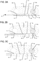
- the fluid delivery cannula 63 can be appropriately positioned along the channel 41 as shown in FIGS. 2A-C . That is, as shown in FIG. 2A , when the fluid delivery cannula 63 is positioned at the distal-most end of the channel 41, the external fluid passageway 67 between the distal and proximal seal members 73, 75 communicates with the opening 71 of the distal cylinder 16a, but not with the opening 71 of the proximal cylinder 16b. Thus, the supply of pressurized fluid through the fluid delivery cannula 63 in the position illustrated in FIG. 2A will cause expansion of the distal piston 22a only.
- the external fluid passageway 67 communicates with the openings 71 of both the distal and proximal cylinders 16a, 16b.
- the supply of pressurized fluid through the fluid delivery cannula 63 will cause expansion of both pistons 22a, 22b.
- further retraction of the fluid delivery cannula 63 to the position illustrated in FIG. 2C will cause the external fluid passageway 67 to communicate with the opening 71 of the proximal cylinder 16b but not the distal cylinder 16a.
- supply of pressurized fluid through the fluid delivery cannula 63 in the position illustrated in FIG. 2C will cause expansion of the proximal piston 22b only.
- the expansion of the different extendable support elements can be individually controlled. That may be useful, for example, in order to adjust the height of each extendable support element to best fit the anatomy of the patient. Individual adjustment may also be useful for providing a specific angular correction to the patient's spine. For example, by providing greater expansion at the anterior portion of the spine than the posterior portion of the spine, the implant 10 may decompress nerve roots while also providing lordosis correction.
- FIGS. 1-3 is desirably structured to be used in a PLIF technique. That is, the generally linear shape of the implant 10 between the distal and proximal ends of the implant may be particularly suitable for inserting two such implants 10 into an intervertebral space (one on either side of the spine) along a posterior to anterior direction, such that the distal end of the implant is positioned more anteriorly with respect to the spine than the more posteriorly positioned proximal end of the implant.
- the same operative components discussed above can also be included in implants structured to be used in a TLIF technique or along a lateral approach.
- an implant structured to be used in a lateral approach may have a similar configuration to that discussed above, but may be sized to cover a substantial portion of the disc space.
- the same operative components discussed above can be incorporated into an implant having an overall kidney bean-like shape.
- the channel for receiving the fluid delivery cannula may be linear between the cylinders, as shown in the above-discussed figures, or it may follow an arcuate path. If the channel is arcuate, the fluid delivery cannula may have a corresponding arcuate shape or may be flexible to conform to the path of the channel.
- FIGS. 1-3 allows for individual control of the amount of expansion at different locations along the implant 10 by allowing for individual actuation of the extendable support elements positioned at different locations within the implant 10, similar individual control of the amount of expansion at different locations along the implant 10 may be provided in other ways.
- the same expansion pressure may be simultaneously applied to the different locations along the implant 110, while those different locations can be individually locked to restrain expansion at the selected location(s) during the application of such expansion pressure.
- FIGS. 4-5 illustrate components of an intervertebral implant system 101 in accordance with another embodiment of the present invention.
- the system 101 includes an implant 110 having a body or housing 111 and multiple extendable support elements that are each expandable such that their top ends 105 are movable away from the housing 111.
- the extendable support elements may be in the form of any of the extendable support elements disclosed in the '620 Patent or the '854 Application.
- the extendable support elements may also be in the form of pistons 122a and 122b slidably received around associated cylindrical posts 116a, 116b affixed to the housing 111, as shown in FIGS. 4 and 6-8 .
- the pistons 122a and 122b may be hollow, cylindrical structures received around associated posts 116a, 116b, which posts 116a, 116b may also be hollow, cylindrical structures having respective pressure channels 141a at their bottom ends for supplying pressurized fluid.
- a seal member 123 which may be in the form of an o-ring, may be positioned so as to seal the sliding interfaces between the pistons 122a, 122b and the respective posts 116a, 116b, in order to prevent the pressurized fluid from escaping through those interfaces.
- the pistons 122a, 122b and posts 116a, 116b may thus operate as part of a hydraulic system like that discussed in the '620 Patent and the '854 Application.
- the pressurized fluid will drive the pistons 122a, 122b to slide outward from the housing 111.
- the posts 116a, 116b may be portions of respective plug elements 114a, 114b affixed to the housing 111 by being secured within respective cylindrical bores 115a, 115b formed through the housing 111.
- the plug elements 114a, 114b may have wide, circular base plates 117a, 117b, which may be secured within the bottoms of the respective bores 115a, 115b.
- Separate alignment rings 119a, 119b may be secured (e.g., welded) within the tops of the respective bores 115a, 115b after the pistons 122a, 122b have been positioned within the bores 115a, 115b, in order to secure and align the pistons 122a, 122b within the implant.
- Such alignment rings 119a, 119b may have outer dimensions matching the inner dimensions of the bores 115a, 115b, and inner dimensions matching the outer profiles of the respective pistons 122a, 122b.
- the inner profiles of the alignment rings 119a, 119b may include inwardly projecting portions or flat surfaces 124 that match recesses 146 along the outer surfaces of the pistons 122a, 122b, in order to constrain the rotational orientations of the pistons 122a, 122b.
- the alignment rings 119a, 119b may also act as a stop to prevent further expansion of the pistons 122a, 122b beyond a predetermined height.
- the pistons 122a, 122b may each include at least one projecting feature that will engage the underside of the respective alignment rings 119a, 119b to prevent further expansion of the pistons.
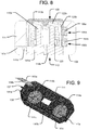
- the posts 116a, 116b of the plug elements 114a, 114b may have pressure channels 141a formed therein, which communicate with a network of pressure channels 141b and 141c formed in the housing 111, as shown in FIGS. 8-9 . That is, the housing 111 includes a longitudinal pressure channel 141b communicating with a pressure input port 138, into which the pressurized fluid is supplied.
- the network of pressure channels formed in the housing 111 may also include transverse pressure channels 141c extending from the longitudinal pressure channel 141b and communicating with the pressure channels 141 a formed in the base plates 117a, 117b of the plug elements 114a, 114b.
- the longitudinal and transverse pressure channels 141b, 141c may be formed by drilling bores into sidewalls of the housing 111, after which plugs (not shown) may be inserted into the resulting openings formed in the sidewalls, such that the only remaining openings into the channel system are the pressure input port 138 and the exits into the pistons 122a, 122b.
- the bottom 112 of the housing 111 has a bottom end surface 108, which is a bone engaging surface for engaging a vertebra on one side (e.g., the inferior side) of the intervertebral space within which the implant 110 is positioned.
- the top ends 105 of the pistons 122a, 122b may represent bone engaging surfaces of the implant 110 for engaging a vertebra on the opposite side of the intervertebral space from the bottom end surface 108 (e.g., the superior side).
- each piston 122a, 122b may be connected to a respective plate element 113a, 113b that has a top end surface 109 representing a bone engaging surface for engaging the vertebra on the opposite side of the intervertebral space from the bottom end surface 108, as shown in FIGS. 4-8 .
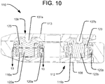
- both piston top ends 105 may be connected to a common top end plate 113 having a top end surface 109 representing a bone engaging surface for engaging the vertebra on the opposite side of the intervertebral space from the bottom end surface 108, as shown in FIG. 10 .
- the top end plate 113 may be connected to each piston 122a, 122b by a pivotable connection 107a, 107b, such as a rotatable pin connection, so that the top end plate 113 can be angled with respect to each piston 122a, 122b to accommodate different amounts of translation of each piston 22a, 22b.
- a pivotable connection 107a, 107b such as a rotatable pin connection
- the implant 110 also includes a locking system having multiple locking elements 120a, 120b secured to the housing 111 and configured to lock the translational positions of the pistons 122a, 122b.
- the locking elements 120a, 120b may have a cylindrical shape configured to be positioned around the respective pistons 122a, 122b.
- the locking elements 120a, 120b may include at least one feature projecting inwardly from an inner surface thereof, and the pistons 122a, 122b may include at least one corresponding feature projecting outwardly from an outer surface thereof.
- Those features are configured to engage and disengage one another by rotation of the locking elements 120a, 120b with respect to the pistons 122a, 122b. For example, as shown in FIG.
- the pistons 122a, 122b may each include a series of spaced apart ribs 118 projecting from their outer surfaces, and the inner surfaces of the locking elements 120a, 120b may each include a series of spaced apart ribs 121.
- the ribs 121 of the locking element 120a, 120b mesh with the ribs 118 of the associated piston 122a, 122b, thus preventing expansion the piston 122a, 122b.
- the ribs 121 of the locking elements 120a, 120b may be structured and arranged to align and fit within the recesses 146 along the outer surfaces of the pistons 122a, 122b at particular rotational positions of each locking element 120a, 120b (referred to as an "unlocked configuration").
- an unlocked configuration there is clearance between the ribs 118 of a piston 122a, 122b and the ribs 121 of the associated locking element 120a, 120b, thus leaving the pistons 122a, 122b free to translate outwardly under the influence of the pressurized fluid, or free to translate back inwardly so as to collapse the implant if the fluid is depressurized or withdrawn.
- a rack-and-pinion arrangement may be used to control the rotational positions of the locking elements 120a, 120b, and thus the locked and unlocked status of the associated pistons 122a, 122b, as shown in FIG. 11 .
- each locking element 120a, 120b may include a plurality of teeth 164 on the outer surface thereof, in order to engage teeth 170 of a corresponding control rod 168a, 168b, such that the rotational position of each locking element 120a, 120b may be controlled by the linear position of the control rod 168a, 168b within a channel 166a, 166b in the implant housing 111. As shown in FIG.
- the locking elements 120a, 120b are moved to a locked configuration, such that the ribs 121 of the locking elements 120a, 120b are rotated into engagement with the ribs 118 of the pistons 122a, 122b, thus preventing the pistons 122a, 122b from translating outwardly.
- each piston 122a, 122b includes two, diametrically opposed recesses 146, and the locking elements 120a, 120b each include two corresponding sets of ribs 121.
- a single rib 118 may be provided on each piston 122a, 122b. That single rib 118 may be discontinuous in particular circumferential regions with which the ribs 121 of the locking elements 120a, 120b align in the unlocked configuration, so that there is clearance for the pistons 122a, 122b to translate.
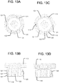
- FIGS. 13A-D which are views of such an alternative arrangement as incorporated into the embodiment of the implant 110 of FIG.
- the pistons 122a, 122b may include three such discontinuous regions, although more or fewer discontinuous regions are also within the scope of the present invention.
- the ribs 121 of the locking element 120 are rotationally aligned with the solid portions of the rib 118 of the piston 122, and thus the piston 122 is prevented from translating outwardly.
- the ribs 121 of the locking element 120 have rotated into alignment with the discontinuous regions of the rib 118 of the piston 122, such that the piston 122 is free to translate outwardly.
- the reverse arrangement (not shown) is also within the scope of the present invention.
- each locking element 120a, 120b instead of a series of spaced apart ribs 121 on the locking elements 120a, 120b, only a single rib 121 having discontinuous regions may be provided on the inner surface of each locking element 120a, 120b.
- the rib 121 of one of the locking elements 120a, 120b may be rotated into engagement with whichever rib 118 of the associated piston 122a, 122b is at that level.
- the expansion of the different pistons can be individually controlled while applying a single fluid pressure to all the pistons.
- any one or more of the pistons can be selectively locked by appropriate manipulation of the position of the associated control rod, such that the remaining unlocked pistons continue to translate outward from the implant housing.
- a delivery tool 100 for inserting and positioning the implant 110 within the intervertebral space may include respective sliders 105a, 105b linearly movable by a user along at least a portion of the delivery tool 100, as shown in FIG. 14 .
- the delivery tool 100 may be securely attached to the proximal end of the implant 110 by a delivery tool anchor 137 (see FIGS. 4-7 ), which may include a threaded bore formed in the implant 110.
- the delivery tool 100 may include a conduit for communicating with the pressure input port 138, in order to supply the pressurized fluid to the implant 110.
- the delivery tool anchor 137 having a threaded bore for secure attachment to the delivery tool 100 need not be a separate opening in the implant 110 from the pressure input port 139 for supplying pressurized fluid, and both functions can be performed by a common opening, as shown in the embodiment of FIGS. 16-19 .
- the locking elements 120a, 120b are desirably configured such that fully retracting the associated control rods 168a, 168b from the implant 110, such as when the delivery tool 100 is disconnected and removed from the patient's body, will leave the locking elements 120a, 120b in a locked configuration.
- a further alternative embodiment in accordance with the present invention includes rotatable locking elements 220 similar to those of the embodiment of FIGS. 4-13D , except that the locking elements 220 are configured to selectively define a maximum amount of permitted movement of the associated piston 222, rather than locking the position of the associated piston 222.
- the inner surface of the locking element 220 includes a series of spaced apart ribs 221, where each successive rib 221 extends to a different, increasing circumferential position along the inner surface of the locking element 220.
- the associated piston 222 may include a pin 218 projecting from its outer surface.
- each locking element 220 can be rotated to a desired position so as to define a maximum amount of expansion of the associated piston 222, by aligning the rib 221 corresponding to the desired height such that it is vertically above the pin 218. In that manner, expansion of the piston 222 by the pressurized fluid will cause the piston to translate until it engages and stops at the aligned rib 221. The height of the piston 222 may then be locked at that position by fully retracting the associated control rod 268, thus rotating the locking element 220 until the pin 218 is constrained between two adjacent ribs 221.
- Each locking element 220 and piston 222 combination need not have only one pin 218 and one corresponding series of ribs 221, however.
- multiple pins 218, each with a corresponding series of ribs 221, may be equally spaced apart about the circumference of the piston 218 and locking element 220.
- the embodiment illustrated in FIGS. 16-17 has three pins 218 equally spaced about the circumference of each piston 222.
- FIGS. 16-19 in which reference numerals like those in earlier embodiments refer to analogous elements (and therefore not all numbered elements will be separately discussed again), illustrate an embodiment of an implant 210 having distal and proximal locking elements 220a, 220b like that shown in FIG. 15 .
- the locking elements 220a, 220b may be individually controlled by respective control rods 268a, 268b so that the associated pistons 222a, 222b can be expanded to different desired heights, and the bone engaging component(s) (e.g., top end plate 213) can thus be translated and angled, as with the previously-discussed embodiments.
- Many of the other structures of the embodiment of FIGS. 16-19 are substantially the same as those of the embodiment of FIGS.
- the posts 216a, 216b of the embodiment of FIGS. 16-19 may be portions of a single bottom plate element 214.
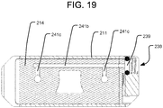
- that plate element 214 may include a network of longitudinal and transverse pressure channels 241b, 241c similar to those of the embodiment of FIGS. 4-13D , such that the network of channels communicates the pressurized fluid from a pressure input port 238 to the pistons 222a, 222b.
- the pressure input port 238 may include a threaded section for secure attachment to a delivery tool for delivering the implant 210, such that the pressure input port 238 also functions like the delivery tool anchor 137 discussed above.
- a sealing member, such as o-ring 239, may also be provided within the pressure input port 238, so as to seal the fluid connection between the pressure input port 238 and the delivery tool.
- FIGS. 16-19 differ from the embodiment of FIGS. 4-13 in that the embodiment of FIGS. 16-19 does not have separate alignment rings like those illustrated in FIGS. 16A-B .
- similarly shaped alignment components may be integrally formed with the housing 211 of the implant 210, or the bores 215a, 215b through the housing 211 may be shaped to constrain the rotational orientations of the pistons 222a, 222b.
- the channel 266a for the control rod 268a that controls the distal locking element 220a opens outwardly through a side wall of the housing 211 along a portion of the longitudinal extent of the housing 211.
- FIGS. 16-19 Such extended opening into the channel 266a through the side wall, which may beneficially allow for more clearance between the control rod 268a and the proximal locking element 220b that it bypasses, may also be included in the embodiment of FIGS. 4-13 , although not shown in those figures.
- the embodiment of FIGS. 16-19 also includes friction rings 225a, 225b compressed between the tops of the locking elements 220a, 220b and the underside of the top of the housing 221 in the assembled configuration.
- the friction rings 225a, 225b may be made out of rubber or a polymeric material that has a relatively high coefficient of friction, so that there is enough resistance to rotation of the locking elements 220a, 220b that their rotational positions are maintained when not intentionally rotated by the user using the control rods 268a, 268b.
- Such friction rings although not shown in FIGS. 4-13 , can also be used in the embodiment of those figures.
- each of the implants 110, 210 between the distal and proximal ends of the implant may be particularly suitable for inserting two such implants 110, 210 into an intervertebral space (one on either side of the spine) along a posterior to anterior direction, such that the distal end of the implant is positioned more anteriorly with respect to the spine than the more posteriorly positioned proximal end of the implant.
- the same operative components discussed above can also be included in implants structured to be used in a TLIF technique or along a lateral approach.
- an implant structured to be used in a lateral approach may have a similar configuration to one of those discussed above, but may be sized to cover a substantial portion of the disc space.
- an implant structured to be used in a TLIF technique the same operative components discussed above can be incorporated into an implant having an overall kidney bean-like shape.
- the channels for receiving the control rods may be linear between the locking elements, as shown in the above-discussed figures, or the channels may follow an arcuate path. If the channels are arcuate, the control rods may have a corresponding arcuate shape or may be flexible to conform to the paths of the channels.
- a single extendable support element which may include a translating piston 322 driven by a pressurized fluid, may be provided between a housing 311 of the implant 310 and a top end plate 313.
- Reference numerals in FIG. 20 that are like those in earlier embodiments refer to analogous elements, and therefore not all numbered elements will be separately discussed again.
- the implant of FIG.20 may include two or more locking elements 320 similar to those discussed above at different locations across the implant 310, in order to individually control the amount of expansion of the top plate 313 at the location of each locking element 320.
- the implant 310 may include a distal locking element 320a and a proximal locking element 320b, with the extendable support element (e.g., piston 322) being centrally located therebetween.
- the extendable support element may be actuated to drive the movement of the top end plate 313 away from the housing of the implant, and each locking element 320a, 320b can be individually manipulated to control the amount of expansion of the top end plate 313 at the distal and proximal ends.
- the locking elements 320a, 320b may each be configured to lock the expanded position of the top end plate 313 at the location of the locking element by lockingly engaging a structure connected to the top end plate 313.
- the top end plate 313 may include downwardly extending shafts 326a, 326b coupled thereto, which shafts have outer surfaces with similar configurations to the pistons described above (i.e., each having a series of spaced apart ribs projecting from the outer surface), where the shafts 326a, 326b are received within open interior regions of the respective locking elements 320a, 320b and are lockingly engageable by the locking elements in similar ways to those described above (e.g., by rotational engagement with inwardly projecting ribs 321 of the locking elements).
- the top end plate 313 may be indirectly coupled to the housing 311 (e.g., via the extendable support element and/or locking elements) by pivotable connections, so that the top end plate 313 can achieve angled orientations with respect to the housing 311 and so that the top end plate 313 can continue to translate at the location of a locking element 320 that is in an unlocked configuration, even when the other locking element is in a locked configuration. For example, as shown in FIG.
- the shafts 326a, 326b may be coupled to the top end plate 313 by respective pivotable connections 307a, 307b, such as rotatable pin connections, and the piston 322 may contact the plate 313 in such a way that the contact point can slide along the plate, so as to not over-constrain the top end plate 313.
Landscapes
- Health & Medical Sciences (AREA)
- Engineering & Computer Science (AREA)
- Biomedical Technology (AREA)
- Orthopedic Medicine & Surgery (AREA)
- Neurology (AREA)
- Transplantation (AREA)
- Life Sciences & Earth Sciences (AREA)
- Public Health (AREA)
- Heart & Thoracic Surgery (AREA)
- Vascular Medicine (AREA)
- Cardiology (AREA)
- Animal Behavior & Ethology (AREA)
- General Health & Medical Sciences (AREA)
- Oral & Maxillofacial Surgery (AREA)
- Veterinary Medicine (AREA)
- Physical Education & Sports Medicine (AREA)
- Chemical & Material Sciences (AREA)
- Dispersion Chemistry (AREA)
- Prostheses (AREA)
- Surgical Instruments (AREA)
Abstract
Description
- This application claims the benefit of the filing date of United States Provisional Patent Application No.
62/393,380 filed September 12, 2016 - Intervertebral implants are commonly used in spinal surgery, such as in interbody fusion procedures, in which an implant (e.g., a spacer or cage) is placed in the disc space between two vertebrae to be fused together. At least a portion of the disc is typically removed before the implant is positioned in the intervertebral space, and the implant may be supplemented with bone graft material to promote fusion of the vertebrae. Interbody fusion procedures may also be performed in conjunction with other types of fixation, such as pedicle screw fixation, to provide additional stability, particularly while the vertebrae fuse together.
- Different interbody fusion procedures can be distinguished by their location along the spine (e.g., in the cervical, thoracic, or lumbar regions); by the type of implant used; and by the surgical approach to the intervertebral space, in which different surgical approaches often imply different structural characteristics of the implant or implants used. Different surgical approaches to the spine include anterior, posterior, and lateral. Examples of interbody fusion techniques performed along a posterior approach include posterior lumbar interbody fusion (PLIF) and transforaminal lumbar interbody fusion (TLIF). PLIF techniques typically include positioning two intervertebral implants into the intervertebral space along a posterior to anterior direction, with one implant being positioned towards the left side of the spine and one implant being positioned towards the right side of the spine. The implants used in such PLIF techniques typically have a straight shape, in that they extend along a central axis. TLIF techniques, by contrast, typically include positioning one intervertebral implant into the intervertebral space (often towards the anterior portion of the intervertebral space) from the posterior of the patient, but the spine is approached on one side from a more lateral position than in PLIF techniques. The implants used in such TLIF techniques are often curved, such that they have an overall kidney bean-like shape. Interbody fusion techniques performed along a lateral approach, on the other hand, often involve implants that are generally symmetric along their linear longitudinal axis (e.g., having a substantially rectangular or oval shape), but the implants are typically larger than those used in PLIF or TLIF techniques. That is, intervertebral implants used in lateral approaches often cover a substantial portion of the disc space.
- Included among the different types of intervertebral implants are expandable implants. Such implants often have an initially contracted configuration, such that they have a low profile in the superior-inferior direction, in order to ease insertion into the intervertebral space. Such expandable implants can then be expanded in the superior-inferior direction after implantation, so as to securely engage and stabilize the vertebrae on both sides of the intervertebral space. Examples of expandable intervertebral implants are disclosed in
U.S. Patent No. 8,992,620 ("the '620 Patent") and inU.S. Patent Application No. 15/481,854 filed on April 7, 2017 - Although considerable effort has been devoted in the art to optimization of such intervertebral systems and methods, still further improvement would be desirable.
- The present invention relates to expandable spinal interbody implants, as well as to systems comprising the same and methods of operating the same.
- In accordance with aspects of the invention, a spinal implant for placement between first and second vertebral bodies preferably includes a body and at least first and second extendable support elements connected to the body at respective first and second locations. The body may have a first surface for engaging the first vertebral body. The first and second extendable support elements are each desirably configured to expand such that a respective first and second end of the extendable support element moves away from the body. A spinal implant system comprising such a spinal implant preferably further includes a tool selectively positionable with respect to the implant so as to independently or simultaneously expand the first and second extendable support elements.
- According to some further aspects of the above spinal implant system, the spinal implant may be configured to allow the tool to move within the spinal implant to expand the first and second extendable support elements. In some yet further aspects of such spinal implant system, the spinal implant may be configured to allow the tool to move longitudinally within the spinal implant to expand the first and second extendable support elements. According to some even further aspects, such spinal implant may include a channel extending between the first and second extendable support elements, such that the longitudinal movement of the tool is within the channel.
- According to some other aspects of the above spinal implant system, each of the first and second extendable support elements may include a piston slidably received within a cylinder. In some yet further aspects of such spinal implant system, the first and second extendable support elements may be configured to be extended by a fluid. According to some even further aspects, the spinal implant may include a channel extending between the first and second extendable support elements. In some such aspects, the tool may supply the fluid to the first and second extendable support elements, and the channel of the spinal implant may be configured to allow the tool to move therealong to selectively supply the fluid to the first and second extendable support elements. In some other of such aspects, the tool may include an internal fluid passageway. In some even further aspects, the channel of the spinal implant may be adapted to receive the tool therein, and, when the tool is received within the channel, an exterior fluid passageway may be defined between an inner surface of the channel and an exterior surface of the tool. That exterior fluid passageway may communicate with the internal fluid passageway via at least one exit port of the tool. In some further aspects of such spinal implant system, the tool may be longitudinally movable along the channel, such that the exterior fluid passageway can be moved to selectively communicate with either or both of the first and second expandable support elements. In some other further aspects of the spinal implant system, the exterior fluid passageway may be defined between a first seal member and a second seal member spaced apart along a length of the tool, which seal members may be configured to sealingly engage the inner surface of the channel. In some yet other further aspects of the spinal implant system, the exterior fluid passageway may be at least partially defined by a recessed portion of the exterior surface of the tool.
- According to some other aspects of the above spinal implant system, the first end of the first extendable support element and the second end of the second extendable support element may be connected by a plate having a second surface for engaging the second vertebral body. In some yet further aspects of such spinal implant system, the first end of the first extendable support element may be connected to the plate by a first pivotable connection and the second end of the second extendable support element may be connected to the plate by a second pivotable connection.
- In accordance with other aspects of the invention, a spinal implant for placement between first and second vertebral bodies preferably includes a body, at least one extendable support element connected to the body, first and second movable members having respective first and second ends movable away from the body, and first and second locking elements. The first movable member and the first locking element are preferably at a first location, and the second movable member and the second locking element are preferably at a second location. The first and second locking elements are desirably selectively lockable such that, when the first locking element is locked, the first locking element restrains movement of the first movable member away from the body without restraining movement of the second movable member away from the body, and, when the second locking element is locked, the second locking element restrains movement of the second movable member away from the body without restraining movement of the first movable member away from the body.
- According to some further aspects of the above spinal implant, the first locking element, when locked, may restrain movement of the first movable member away from the body by defining a maximum amount of permitted movement of the first movable member away from the body, and the second locking element, when locked, may restrain movement of the second movable member away from the body by defining a maximum amount of permitted movement of the second movable member away from the body. In some yet further aspects of such spinal implant, the first locking element may be configured to selectively vary the maximum amount of permitted movement of the first movable member away from the body when the first locking element is locked, and the second locking element may be configured to selectively vary the maximum amount of permitted movement of the second movable member away from the body when the second locking element is locked.
- According to some other aspects of the above spinal implant, the first and second locking elements may each be rotatable so as to move between a locked configuration and an unlocked configuration. In some yet further aspects of such spinal implant, the first and second locking elements may each have a cylindrical shape defining an open interior space. According to some even further aspects, the extendable support element may include a first extendable support element and a second extendable support element, with the first extendable support element being received within the open interior space of the first locking element, and the second extendable support element being received within the open interior space of the second locking element. In some even further aspects, an inner surface of the first locking element may include a first inner projecting feature, and an outer surface of the first extendable support element may include a first outer projecting feature. The first inner projecting feature and the first outer projecting feature may be arranged to selectively engage and disengage one another based on a rotational position of the first locking element. An inner surface of the second locking element may similarly include a second inner projecting feature, and an outer surface of the second extendable support element may include a second outer projecting feature. The second inner projecting feature and the second outer projecting feature may likewise be arranged to selectively engage and disengage one another based on a rotational position of the second locking element. In some such aspects, the first inner projecting feature, the first outer projecting feature, the second inner projecting feature, and the second outer projecting feature may each include a plurality of projecting ribs. In some other of such aspects, the first inner projecting feature may include a series of first projecting ribs, each of which may extend to a different radial position along the inner surface of the first locking element, and the second inner projecting feature may include a series of second projecting ribs, each of which may extend to a different radial position along the inner surface of the second locking element. According to some aspects, the first locking element may include a plurality of teeth along an outer surface of the first locking element, which teeth may be adapted for engagement by a first control tool to rotate the first locking element so as to move the first locking element between a locked configuration and an unlocked configuration.
- According to some other aspects of the above spinal implant, the extendable support element may include a first extendable support element and a second extendable support element, with the first movable member being a portion of the first extendable support element, and the second movable member being a portion of the second extendable support element.
- According to some other aspects of the above spinal implant, the first and second movable members may be connected by a plate having a second surface for engaging the second vertebral body. In some yet further aspects of such spinal implant, the first and second movable members are connected to the plate by a respective first and second pivotable connection.
- In accordance with yet other aspects of the invention, a spinal implant system may comprise a spinal implant, as described above, and first and second control rods. The first and second control rods are desirably adapted to selectively lock the respective first and second locking elements of the implant.
- According to some further aspects of the above spinal implant system, the first and second control rods may be adapted to selectively lock the respective first and second locking element by linear movement of the respective first and second control rod within the spinal implant. In some yet further aspects of such spinal implant system, the first and second control rods may each include a plurality of teeth arranged to engage the respective first and second locking elements so as to control the selective locking of the respective first and second locking elements.
-
-
FIG. 1 is a perspective view of a spinal implant system in accordance with one embodiment of the present invention. -
FIGS. 2A-C are cross-sectional plan views about line 2-2 of the embodiment ofFIG. 1 in different configurations. -
FIG. 3A is a side elevation view of an embodiment of a spinal implant system having a top end plate. -
FIG. 3B is a perspective view of the spinal implant system ofFIG. 3A . -
FIG. 4 is an exploded, perspective view of a spinal implant system in accordance with another embodiment of the present invention. -
FIG. 5 is a perspective view of the spinal implant system ofFIG. 4 . -
FIG. 6 is a perspective, side cross-sectional view about the longitudinal axis of the spinal implant system ofFIG. 4 . -
FIG. 7 is a cross-sectional side elevation view about the longitudinal axis of the spinal implant system ofFIG. 4 . -
FIG. 8 is a cross-sectional rear elevation view about line 8-8 inFIG. 7 . -
FIG. 9 is a perspective, bottom cross-sectional view of the spinal implant system ofFIG. 7 about line 9-9. -
FIG. 10 is a cross-sectional side elevation view about the longitudinal axis of a variation on the embodiment ofFIG. 4 . -
FIG. 11 is a perspective, top cross-sectional view of the spinal implant system ofFIG. 7 about line 11-11. -
FIGS. 12A-B are plan views of locking components of the embodiment ofFIG. 4 in different configurations. -
FIG. 13A is a cross-sectional plan view about line 13-13 of the alternative locking component illustrated inFIG. 10 in a locked configuration. -
FIG. 13B is a side, cross-sectional view about the implant's longitudinal axis of the locking component ofFIG. 13A in a locked configuration. -
FIG. 13C is a cross-sectional plan view about line 13-13 of the alternative locking component illustrated inFIG. 10 in an unlocked configuration. -
FIG. 13D is a side, cross-sectional view about the implant's longitudinal axis of the locking component ofFIG. 13A in an unlocked configuration. -
FIG. 14 is a perspective view of the spinal implant system ofFIG. 4 including a delivery tool. -
FIG. 15 is a perspective view of a locking element in accordance with another embodiment of the invention. -
FIGS. 16A-B are exploded, perspective views (taken from different angles) of a spinal implant system in accordance with an embodiment of the invention including the locking element ofFIG. 15 . -
FIG. 17 is a cross-sectional plan view about line 17-17 of the spinal implant system ofFIG. 16B . -
FIG. 18 is a cross-sectional side elevation view about the longitudinal axis of the spinal implant system ofFIG. 17 . -
FIG. 19 is a bottom cross-sectional view about line 19-19 of the spinal implant system ofFIG. 16B . -
FIG. 20 is a cross-sectional side elevation view about the longitudinal axis of a spinal implant system in accordance with another embodiment of the present invention. -
FIGS. 1-3 illustrate components of anintervertebral implant system 1 in accordance with an embodiment of the present invention. Thesystem 1 includes animplant 10 having a body orhousing 11 and multiple extendable support elements that are expandable such that their top ends 5 are movable away from thehousing 11. The extendable support elements may be in the form of any of the extendable support elements disclosed in the '620 Patent or the '854 Application. For example, as shown, the extendable support elements are in the form ofpistons cylinders housing 11. The sliding of thepistons cylinders pistons implant 10. Thepistons cylinders pistons cylinders FIGS. 1-3 , theimplant 10 may also include a locking system to lock the positions of thepistons housing 11 once expanded. The locking system may include any of the structures of the locking systems disclosed in the '620 Patent and the '854 Application, and the locking system may also be unlockable to allow the pistons to collapse (e.g., to reposition theimplant 10 or to remove it from the body). - As discussed below, each extendable support element (e.g., piston 22) can be independently actuated so as to independently expand with respect to the
housing 11. The bottom 12 of thehousing 11 has abottom end surface 8, which is a bone engaging surface for engaging a vertebra on one side (e.g., the inferior side) of the intervertebral space within which theimplant 10 is positioned. The top ends 5 of thepistons implant 10 for engaging a vertebra on the opposite side of the intervertebral space from the bottom end surface 8 (e.g., the superior side). Alternatively, each pistontop end 5 may be connected to a respective plate element (not shown) that has a top end surface representing a bone engaging surface for engaging the vertebra on the opposite side of the intervertebral space from thebottom end surface 8, similar to the plate elements in the embodiment ofFIGS. 4-8 . In yet a further alternative, both piston top ends 5 may be connected to a commontop end plate 13 having atop end surface 9 representing a bone engaging surface for engaging the vertebra on the opposite side of the intervertebral space from thebottom end surface 8, as shown inFIGS. 3A-B . In such an embodiment, thetop end plate 13 may be connected to eachpiston top end plate 13 can be angled with respect to eachpiston piston - The
intervertebral implant system 1 in accordance with the present invention also includes a tool for actuating the expansion of the extendable support elements. The tool may include afluid delivery cannula 63 for delivering a pressurized fluid to thecylinders pistons fluid delivery cannula 63 is in the form of a shaft having aninternal fluid passageway 65 extending along its length. Thefluid delivery cannula 63 is desirably configured to independently control the expansion of each extendable support element. Thefluid delivery cannula 63 may also be configured to control the expansion of both extendable support elements at the same time. For example, thefluid delivery cannula 63 is selectively positionable within apressure channel 41 extending between both of thecylinders cylinders respective opening 71. Thefluid delivery cannula 63 can thus selectively communicate with either or both of thecylinders channel 41. In that regard, when thefluid delivery cannula 63 is received within thechannel 41, anexterior fluid passageway 67 is defined between an inner surface of thechannel 41 and an exterior surface of thefluid delivery cannula 63. The longitudinal extent of theexterior fluid passageway 67 may be defined by adistal seal member 73, which may be in the form of an o-ring positioned around the exterior surface of thefluid delivery cannula 63 towards its distal end, and aproximal seal member 75, which may also be in the form of an o-ring positioned around the exterior surface of thefluid delivery cannula 63 and spaced proximally from thedistal seal member 73. The volume of theexterior fluid passageway 67 may also be defined by a recessedgroove 69 within the exterior surface of thefluid delivery cannula 63. As shown inFIGS. 2A-C , that recessedgroove 69 may be an annular groove that extends entirely around the circumference of thefluid delivery cannula 63 between the distal andproximal seal members internal fluid passageway 65 may thus be communicated to theexternal fluid passageway 67 via at least oneexit port 77 in thefluid delivery cannula 63. - In order to selectively actuate the extendable support elements, the
fluid delivery cannula 63 can be appropriately positioned along thechannel 41 as shown inFIGS. 2A-C . That is, as shown inFIG. 2A , when thefluid delivery cannula 63 is positioned at the distal-most end of thechannel 41, theexternal fluid passageway 67 between the distal andproximal seal members opening 71 of thedistal cylinder 16a, but not with theopening 71 of theproximal cylinder 16b. Thus, the supply of pressurized fluid through thefluid delivery cannula 63 in the position illustrated inFIG. 2A will cause expansion of thedistal piston 22a only. By retracting thefluid delivery cannula 63 to the position illustrated inFIG 2B , theexternal fluid passageway 67 communicates with theopenings 71 of both the distal andproximal cylinders FIG. 2B , the supply of pressurized fluid through thefluid delivery cannula 63 will cause expansion of bothpistons fluid delivery cannula 63 to the position illustrated inFIG. 2C will cause theexternal fluid passageway 67 to communicate with theopening 71 of theproximal cylinder 16b but not thedistal cylinder 16a. Thus, supply of pressurized fluid through thefluid delivery cannula 63 in the position illustrated inFIG. 2C will cause expansion of theproximal piston 22b only. - By manipulating the
fluid delivery cannula 63 as discussed above, the expansion of the different extendable support elements can be individually controlled. That may be useful, for example, in order to adjust the height of each extendable support element to best fit the anatomy of the patient. Individual adjustment may also be useful for providing a specific angular correction to the patient's spine. For example, by providing greater expansion at the anterior portion of the spine than the posterior portion of the spine, theimplant 10 may decompress nerve roots while also providing lordosis correction. - The above-described embodiment illustrated in
FIGS. 1-3 is desirably structured to be used in a PLIF technique. That is, the generally linear shape of theimplant 10 between the distal and proximal ends of the implant may be particularly suitable for inserting twosuch implants 10 into an intervertebral space (one on either side of the spine) along a posterior to anterior direction, such that the distal end of the implant is positioned more anteriorly with respect to the spine than the more posteriorly positioned proximal end of the implant. However, the same operative components discussed above can also be included in implants structured to be used in a TLIF technique or along a lateral approach. For example, an implant structured to be used in a lateral approach may have a similar configuration to that discussed above, but may be sized to cover a substantial portion of the disc space. As for an implant structured to be used in a TLIF technique, the same operative components discussed above can be incorporated into an implant having an overall kidney bean-like shape. In such an embodiment, the channel for receiving the fluid delivery cannula may be linear between the cylinders, as shown in the above-discussed figures, or it may follow an arcuate path. If the channel is arcuate, the fluid delivery cannula may have a corresponding arcuate shape or may be flexible to conform to the path of the channel. - Although the embodiment of
FIGS. 1-3 allows for individual control of the amount of expansion at different locations along theimplant 10 by allowing for individual actuation of the extendable support elements positioned at different locations within theimplant 10, similar individual control of the amount of expansion at different locations along theimplant 10 may be provided in other ways. For example, in the embodiment ofFIGS. 4-12 , discussed below, the same expansion pressure may be simultaneously applied to the different locations along theimplant 110, while those different locations can be individually locked to restrain expansion at the selected location(s) during the application of such expansion pressure. -
FIGS. 4-5 illustrate components of an intervertebral implant system 101 in accordance with another embodiment of the present invention. The system 101 includes animplant 110 having a body orhousing 111 and multiple extendable support elements that are each expandable such that their top ends 105 are movable away from thehousing 111. The extendable support elements may be in the form of any of the extendable support elements disclosed in the '620 Patent or the '854 Application. The extendable support elements may also be in the form ofpistons cylindrical posts housing 111, as shown inFIGS. 4 and6-8 . For example, in the illustrated embodiment, thepistons posts respective pressure channels 141a at their bottom ends for supplying pressurized fluid. Aseal member 123, which may be in the form of an o-ring, may be positioned so as to seal the sliding interfaces between thepistons respective posts pistons posts posts respective pistons pistons housing 111. - As shown in
FIGS. 4 and6-9 , theposts respective plug elements housing 111 by being secured within respectivecylindrical bores housing 111. Theplug elements circular base plates respective bores Separate alignment rings respective bores pistons bores pistons bores respective pistons flat surfaces 124 that match recesses 146 along the outer surfaces of thepistons pistons pistons pistons respective alignment rings posts plug elements pressure channels 141a formed therein, which communicate with a network ofpressure channels housing 111, as shown inFIGS. 8-9 . That is, thehousing 111 includes alongitudinal pressure channel 141b communicating with apressure input port 138, into which the pressurized fluid is supplied. The network of pressure channels formed in thehousing 111 may also includetransverse pressure channels 141c extending from thelongitudinal pressure channel 141b and communicating with thepressure channels 141 a formed in thebase plates plug elements transverse pressure channels housing 111, after which plugs (not shown) may be inserted into the resulting openings formed in the sidewalls, such that the only remaining openings into the channel system are thepressure input port 138 and the exits into thepistons - The
bottom 112 of thehousing 111 has abottom end surface 108, which is a bone engaging surface for engaging a vertebra on one side (e.g., the inferior side) of the intervertebral space within which theimplant 110 is positioned. The top ends 105 of thepistons implant 110 for engaging a vertebra on the opposite side of the intervertebral space from the bottom end surface 108 (e.g., the superior side). Alternatively, thetop end 105 of eachpiston respective plate element top end surface 109 representing a bone engaging surface for engaging the vertebra on the opposite side of the intervertebral space from thebottom end surface 108, as shown inFIGS. 4-8 . In yet a further alternative, both piston top ends 105 may be connected to a commontop end plate 113 having atop end surface 109 representing a bone engaging surface for engaging the vertebra on the opposite side of the intervertebral space from thebottom end surface 108, as shown inFIG. 10 . In such an embodiment, thetop end plate 113 may be connected to eachpiston pivotable connection top end plate 113 can be angled with respect to eachpiston piston - The
implant 110 also includes a locking system having multiple lockingelements housing 111 and configured to lock the translational positions of thepistons locking elements respective pistons locking elements pistons locking elements pistons FIG. 4 , thepistons ribs 118 projecting from their outer surfaces, and the inner surfaces of thelocking elements ribs 121. In particular rotational orientations of each lockingelement ribs 121 of thelocking element ribs 118 of the associatedpiston piston ribs 121 of thelocking elements recesses 146 along the outer surfaces of thepistons element ribs 118 of apiston ribs 121 of the associated lockingelement pistons - A rack-and-pinion arrangement may be used to control the rotational positions of the
locking elements pistons FIG. 11 . For example, each lockingelement teeth 164 on the outer surface thereof, in order to engageteeth 170 of acorresponding control rod element control rod channel implant housing 111. As shown inFIG. 12A , in which thecontrol rods locking elements ribs 121 of thelocking elements recesses 146 of thepistons pistons control rods FIG. 12B , thelocking elements ribs 121 of thelocking elements ribs 118 of thepistons pistons - In the arrangement of
FIGS. 12A-B , eachpiston opposed recesses 146, and thelocking elements ribs 121. In an alternative arrangement, rather than a series of spaced apartribs 118, only asingle rib 118 may be provided on eachpiston single rib 118 may be discontinuous in particular circumferential regions with which theribs 121 of thelocking elements pistons FIGS. 13A-D , which are views of such an alternative arrangement as incorporated into the embodiment of theimplant 110 ofFIG. 10 , thepistons FIGS. 13A-B , theribs 121 of thelocking element 120 are rotationally aligned with the solid portions of therib 118 of thepiston 122, and thus thepiston 122 is prevented from translating outwardly. As for the unlocked configuration illustrated inFIGS. 13C-D , theribs 121 of thelocking element 120 have rotated into alignment with the discontinuous regions of therib 118 of thepiston 122, such that thepiston 122 is free to translate outwardly. The reverse arrangement (not shown) is also within the scope of the present invention. That is, instead of a series of spaced apartribs 121 on thelocking elements single rib 121 having discontinuous regions may be provided on the inner surface of each lockingelement pistons 122a, 12b at its current level of displacement, therib 121 of one of thelocking elements rib 118 of the associatedpiston - By manipulating the control rods, and thus the locked and unlocked configurations of the pistons, as discussed above, the expansion of the different pistons can be individually controlled while applying a single fluid pressure to all the pistons. For example, by applying a pressure to the pressure channels sufficient to expand all of the pistons, any one or more of the pistons can be selectively locked by appropriate manipulation of the position of the associated control rod, such that the remaining unlocked pistons continue to translate outward from the implant housing.
- In order to control the translational position of the
control rods delivery tool 100 for inserting and positioning theimplant 110 within the intervertebral space may includerespective sliders delivery tool 100, as shown inFIG. 14 . Thedelivery tool 100 may be securely attached to the proximal end of theimplant 110 by a delivery tool anchor 137 (seeFIGS. 4-7 ), which may include a threaded bore formed in theimplant 110. In addition, thedelivery tool 100 may include a conduit for communicating with thepressure input port 138, in order to supply the pressurized fluid to theimplant 110. Thedelivery tool anchor 137 having a threaded bore for secure attachment to thedelivery tool 100 need not be a separate opening in theimplant 110 from the pressure input port 139 for supplying pressurized fluid, and both functions can be performed by a common opening, as shown in the embodiment ofFIGS. 16-19 . Thelocking elements control rods implant 110, such as when thedelivery tool 100 is disconnected and removed from the patient's body, will leave thelocking elements - A further alternative embodiment in accordance with the present invention includes
rotatable locking elements 220 similar to those of the embodiment ofFIGS. 4-13D , except that the lockingelements 220 are configured to selectively define a maximum amount of permitted movement of the associated piston 222, rather than locking the position of the associated piston 222. For example, as shown inFIG. 15 , the inner surface of thelocking element 220 includes a series of spaced apartribs 221, where eachsuccessive rib 221 extends to a different, increasing circumferential position along the inner surface of thelocking element 220. Moreover, the associated piston 222 may include apin 218 projecting from its outer surface. Thus, each lockingelement 220 can be rotated to a desired position so as to define a maximum amount of expansion of the associated piston 222, by aligning therib 221 corresponding to the desired height such that it is vertically above thepin 218. In that manner, expansion of the piston 222 by the pressurized fluid will cause the piston to translate until it engages and stops at the alignedrib 221. The height of the piston 222 may then be locked at that position by fully retracting the associated control rod 268, thus rotating the lockingelement 220 until thepin 218 is constrained between twoadjacent ribs 221. Each lockingelement 220 and piston 222 combination need not have only onepin 218 and one corresponding series ofribs 221, however. In alternative embodiments,multiple pins 218, each with a corresponding series ofribs 221, may be equally spaced apart about the circumference of thepiston 218 and lockingelement 220. For example, the embodiment illustrated inFIGS. 16-17 has threepins 218 equally spaced about the circumference of each piston 222. -
FIGS. 16-19 , in which reference numerals like those in earlier embodiments refer to analogous elements (and therefore not all numbered elements will be separately discussed again), illustrate an embodiment of animplant 210 having distal andproximal locking elements FIG. 15 . Thus, in such an embodiment, thelocking elements respective control rods pistons FIGS. 16-19 are substantially the same as those of the embodiment ofFIGS. 4-13D , except that, instead of theposts pistons respective plug elements posts FIGS. 16-19 may be portions of a singlebottom plate element 214. As shown inFIG. 19 , thatplate element 214 may include a network of longitudinal andtransverse pressure channels FIGS. 4-13D , such that the network of channels communicates the pressurized fluid from apressure input port 238 to thepistons pressure input port 238 may include a threaded section for secure attachment to a delivery tool for delivering theimplant 210, such that thepressure input port 238 also functions like thedelivery tool anchor 137 discussed above. A sealing member, such as o-ring 239, may also be provided within thepressure input port 238, so as to seal the fluid connection between thepressure input port 238 and the delivery tool. - Other differences between the embodiment of
FIGS. 16-19 and the embodiment ofFIGS. 4-13 include the fact that the embodiment ofFIGS. 16-19 does not have separate alignment rings like those illustrated inFIGS. 16A-B . Instead, similarly shaped alignment components may be integrally formed with thehousing 211 of theimplant 210, or thebores housing 211 may be shaped to constrain the rotational orientations of thepistons FIG. 16A , thechannel 266a for thecontrol rod 268a that controls thedistal locking element 220a opens outwardly through a side wall of thehousing 211 along a portion of the longitudinal extent of thehousing 211. Such extended opening into thechannel 266a through the side wall, which may beneficially allow for more clearance between thecontrol rod 268a and theproximal locking element 220b that it bypasses, may also be included in the embodiment ofFIGS. 4-13 , although not shown in those figures. The embodiment ofFIGS. 16-19 also includes friction rings 225a, 225b compressed between the tops of thelocking elements housing 221 in the assembled configuration. The friction rings 225a, 225b may be made out of rubber or a polymeric material that has a relatively high coefficient of friction, so that there is enough resistance to rotation of thelocking elements control rods FIGS. 4-13 , can also be used in the embodiment of those figures. - The above-described embodiments illustrated in
FIGS. 4-19 are desirably structured to be used in a PLIF technique. That is, the generally linear shape of each of theimplants such implants - Although the locking elements in the embodiments of
FIGS. 4-19 are structured to surround the associated pistons, alternative embodiments in accordance with the present invention need not be arranged in that manner. For example, in another embodiment of the invention illustrated inFIG. 20 , a single extendable support element, which may include a translatingpiston 322 driven by a pressurized fluid, may be provided between ahousing 311 of theimplant 310 and atop end plate 313. Reference numerals inFIG. 20 that are like those in earlier embodiments refer to analogous elements, and therefore not all numbered elements will be separately discussed again. The implant ofFIG.20 may include two or more locking elements 320 similar to those discussed above at different locations across theimplant 310, in order to individually control the amount of expansion of thetop plate 313 at the location of each locking element 320. For example, theimplant 310 may include adistal locking element 320a and aproximal locking element 320b, with the extendable support element (e.g., piston 322) being centrally located therebetween. In operation, the extendable support element may be actuated to drive the movement of thetop end plate 313 away from the housing of the implant, and each lockingelement top end plate 313 at the distal and proximal ends. Rather than engaging extendable support elements positioned therein, thelocking elements top end plate 313 at the location of the locking element by lockingly engaging a structure connected to thetop end plate 313. For example, thetop end plate 313 may include downwardly extendingshafts shafts respective locking elements ribs 321 of the locking elements). Thetop end plate 313 may be indirectly coupled to the housing 311 (e.g., via the extendable support element and/or locking elements) by pivotable connections, so that thetop end plate 313 can achieve angled orientations with respect to thehousing 311 and so that thetop end plate 313 can continue to translate at the location of a locking element 320 that is in an unlocked configuration, even when the other locking element is in a locked configuration. For example, as shown inFIG. 20 , theshafts top end plate 313 by respectivepivotable connections 307a, 307b, such as rotatable pin connections, and thepiston 322 may contact theplate 313 in such a way that the contact point can slide along the plate, so as to not over-constrain thetop end plate 313. - Although the invention herein has been described with reference to particular embodiments, it is to be understood that these embodiments are merely illustrative of the principles and applications of the present invention. It is therefore to be understood that numerous modifications may be made to the illustrative embodiments and that other arrangements may be devised without departing from the spirit and scope of the present invention as defined by the appended claims.
Claims (16)
- A spinal implant for placement between first and second vertebral bodies, comprising:a body having a first surface for engaging a first vertebral body;a first movable member having a first end movable away from the body at a first location;a second movable member having a second end movable away from the body at a second location;at least one extendable support element connected to the body, the first extendable support element being actuatable to expand so as to induce movement of at least one of the first and second ends of the respective first and second movable members away from the body;a first locking element at the first location; anda second locking element at the second location;wherein the first locking element is selectively lockable such that, when locked, the first locking element restrains movement of the first movable member away from the body without restraining movement of the second movable member away from the body; and wherein the second locking element is selectively lockable such that, when locked, the second locking element restrains movement of the second movable member away from the body without restraining movement of the first movable member away from the body.
- The spinal implant of claim 1, wherein, when locked, the first locking element restrains movement of the first movable member away from the body by defining a maximum amount of permitted movement of the first movable member away from the body; and wherein, when locked, the second locking element restrains movement of the second movable member away from the body by defining a maximum amount of permitted movement of the second movable member away from the body.
- The spinal implant of claim 2, wherein the first locking element is configured to selectively vary the maximum amount of permitted movement of the first movable member away from the body when the first locking element is locked; and wherein the second locking element is configured to selectively vary the maximum amount of permitted movement of the second movable member away from the body when the second locking element is locked.
- The spinal implant of any one of claims 1-3, wherein the first and second locking elements are each rotatable so as to move between a locked configuration and an unlocked configuration.
- The spinal implant of claim 4, wherein the first and second locking elements each have a cylindrical shape defining an open interior space.
- The spinal implant of claim 5, wherein the at least one extendable support element includes a first extendable support element and a second extendable support element, wherein the first extendable support element is received within the open interior space of the first locking element, and wherein the second extendable support element is received within the open interior space of the second locking element.
- The spinal implant of claim 6, wherein an inner surface of the first locking element includes a first inner projecting feature, and wherein an outer surface of the first extendable support element includes a first outer projecting feature, the first inner projecting feature and the first outer projecting feature being arranged to selectively engage and disengage one another based on a rotational position of the first locking element; and wherein an inner surface of the second locking element includes a second inner projecting feature, and wherein an outer surface of the second extendable support element includes a second outer projecting feature, the second inner projecting feature and the second outer projecting feature being arranged to selectively engage and disengage one another based on a rotational position of the second locking element.
- The spinal implant of claim 7, wherein the first inner projecting feature, the first outer projecting feature, the second inner projecting feature, and the second outer projecting feature each include a plurality of projecting ribs.
- The spinal implant of any one of claims 7-8, wherein the first inner projecting feature includes a series of first projecting ribs, each of the first projecting ribs extending to a different radial position along the inner surface of the first locking element; and wherein the second inner projecting feature includes a series of second projecting ribs, each of the second projecting ribs extending to a different radial position along the inner surface of the second locking element.
- The spinal implant of claims 5-9, wherein the first locking element includes a plurality of teeth along an outer surface of the first locking element, the teeth being adapted for engagement by a first control tool to rotate the first locking element so as to move the first locking element between the locked configuration and the unlocked configuration.
- The spinal implant of any one of claims 1-10, wherein the at least one extendable support element includes a first extendable support element and a second extendable support element, wherein the first movable member is a portion of the first extendable support element, and wherein the second movable member is a portion of the second extendable support element.
- The spinal implant of any one of claims 1-11, wherein the first movable member and the second movable member are connected by a plate having a second surface for engaging a second vertebral body.
- The spinal implant of claim 12, wherein the first movable member is connected to the plate by a first pivotable connection and the second movable member is connected to the plate by a second pivotable connection.
- A spinal implant system, comprising:the spinal implant of any one of claims 1-13;a first control rod adapted to selectively lock the first locking element of the spinal implant; anda second control rod adapted to selectively lock the second locking element of the spinal implant.
- The spinal implant system of claim 14, wherein the first control rod is adapted to selectively lock the first locking element by linear movement of the first control rod within the spinal implant; and wherein the second control rod is adapted to selectively lock the second locking element by linear movement of the second control rod within the spinal implant.
- The spinal implant system of claim 15, wherein the first and second control rods each include a plurality of teeth arranged to engage the respective first and second locking elements so as to control the selective locking of the respective first and second locking elements.
Applications Claiming Priority (1)
| Application Number | Priority Date | Filing Date | Title |
|---|---|---|---|
| US201662393380P | 2016-09-12 | 2016-09-12 |
Publications (3)
| Publication Number | Publication Date |
|---|---|
| EP3292841A1 true EP3292841A1 (en) | 2018-03-14 |
| EP3292841B1 EP3292841B1 (en) | 2023-05-03 |
| EP3292841B8 EP3292841B8 (en) | 2023-05-31 |
Family
ID=59846511
Family Applications (1)
| Application Number | Title | Priority Date | Filing Date |
|---|---|---|---|
| EP17190437.8A Active EP3292841B8 (en) | 2016-09-12 | 2017-09-11 | Interbody implant with independent control of expansion at multiple locations |
Country Status (4)
| Country | Link |
|---|---|
| US (2) | US10470891B2 (en) |
| EP (1) | EP3292841B8 (en) |
| JP (1) | JP2018043007A (en) |
| AU (1) | AU2017228529B2 (en) |
Cited By (1)
| Publication number | Priority date | Publication date | Assignee | Title |
|---|---|---|---|---|
| WO2023025591A1 (en) * | 2021-08-25 | 2023-03-02 | 25Segments Ag | Expandable intervertebral cage |
Families Citing this family (37)
| Publication number | Priority date | Publication date | Assignee | Title |
|---|---|---|---|---|
| US8597360B2 (en) * | 2004-11-03 | 2013-12-03 | Neuropro Technologies, Inc. | Bone fusion device |
| US8900307B2 (en) | 2007-06-26 | 2014-12-02 | DePuy Synthes Products, LLC | Highly lordosed fusion cage |
| US12232975B2 (en) * | 2008-02-22 | 2025-02-25 | Howmedica Osteonics Corp. | Lockable spinal implant |
| BRPI0910325A8 (en) | 2008-04-05 | 2019-01-29 | Synthes Gmbh | expandable intervertebral implant |
| US9402732B2 (en) | 2010-10-11 | 2016-08-02 | DePuy Synthes Products, Inc. | Expandable interspinous process spacer implant |
| US9532883B2 (en) | 2012-04-13 | 2017-01-03 | Neuropro Technologies, Inc. | Bone fusion device |
| US8663332B1 (en) | 2012-12-13 | 2014-03-04 | Ouroboros Medical, Inc. | Bone graft distribution system |
| US9717601B2 (en) | 2013-02-28 | 2017-08-01 | DePuy Synthes Products, Inc. | Expandable intervertebral implant, system, kit and method |
| US10098757B2 (en) | 2013-03-15 | 2018-10-16 | Neuropro Technologies Inc. | Bodiless bone fusion device, apparatus and method |
| US9186259B2 (en) | 2013-09-09 | 2015-11-17 | Ouroboros Medical, Inc. | Expandable trials |
| US9060876B1 (en) | 2015-01-20 | 2015-06-23 | Ouroboros Medical, Inc. | Stabilized intervertebral scaffolding systems |
| US10500061B2 (en) * | 2015-08-13 | 2019-12-10 | K2M, Inc. | Adjustable spinal implant |
| JP6995789B2 (en) | 2016-06-28 | 2022-01-17 | イーアイティー・エマージング・インプラント・テクノロジーズ・ゲーエムベーハー | Expandable and angle adjustable intervertebral cage |
| CN109640889B (en) | 2016-06-28 | 2021-07-30 | Eit 新兴移植技术股份有限公司 | Expandable Angle Adjustable Articulation Intervertebral Cage |
| AU2017228529B2 (en) * | 2016-09-12 | 2022-03-10 | Vb Spine Us Opco Llc | Interbody implant with independent control of expansion at multiple locations |
| US9883953B1 (en) | 2016-09-21 | 2018-02-06 | Integrity Implants Inc. | Stabilized laterovertically-expanding fusion cage systems with tensioner |
| AU2017251734B2 (en) | 2016-10-26 | 2022-10-20 | Vb Spine Us Opco Llc | Expandable interbody implant with lateral articulation |
| CN110402124B (en) | 2017-01-10 | 2022-03-15 | 整体植入有限公司 | Expandable Interbody Fusion Device |
| US10729560B2 (en) | 2017-01-18 | 2020-08-04 | Neuropro Technologies, Inc. | Bone fusion system, device and method including an insertion instrument |
| US10973657B2 (en) | 2017-01-18 | 2021-04-13 | Neuropro Technologies, Inc. | Bone fusion surgical system and method |
| US10398563B2 (en) | 2017-05-08 | 2019-09-03 | Medos International Sarl | Expandable cage |
| US11344424B2 (en) | 2017-06-14 | 2022-05-31 | Medos International Sarl | Expandable intervertebral implant and related methods |
| US10888430B2 (en) * | 2017-06-21 | 2021-01-12 | NVision Biomedical Technologies, LLC | Expandable/variable lordotic angle vertebral implant and reading system therefor |
| US11224522B2 (en) | 2017-07-24 | 2022-01-18 | Integrity Implants Inc. | Surgical implant and related methods |
| AU2019226567B2 (en) | 2018-03-01 | 2024-04-11 | Integrity Implants Inc. | Expandable fusion device with independent expansion systems |
| US11446156B2 (en) | 2018-10-25 | 2022-09-20 | Medos International Sarl | Expandable intervertebral implant, inserter instrument, and related methods |
| US11426286B2 (en) | 2020-03-06 | 2022-08-30 | Eit Emerging Implant Technologies Gmbh | Expandable intervertebral implant |
| US12329652B2 (en) | 2020-07-20 | 2025-06-17 | Integrity Implants Inc. | Expandable fusion device with independent expansion systems |
| US12472075B2 (en) | 2020-10-27 | 2025-11-18 | Loubert S. Suddaby | Expandable intervertebral fusion implant |
| US11583411B2 (en) * | 2020-10-27 | 2023-02-21 | Loubert S. Suddaby | Expandable intervertebral fusion implant |
| US11850160B2 (en) | 2021-03-26 | 2023-12-26 | Medos International Sarl | Expandable lordotic intervertebral fusion cage |
| US11752009B2 (en) | 2021-04-06 | 2023-09-12 | Medos International Sarl | Expandable intervertebral fusion cage |
| US12453640B2 (en) | 2021-07-16 | 2025-10-28 | Blue Ocean Spine Gmbh | Adjustable spinal implants, associated instruments and methods |
| WO2023285675A1 (en) | 2021-07-16 | 2023-01-19 | Blue Ocean Spine Gmbh | Adjustable intervertebral cage, associated instrument and manufacturing process therefor |
| US12090064B2 (en) | 2022-03-01 | 2024-09-17 | Medos International Sarl | Stabilization members for expandable intervertebral implants, and related systems and methods |
| US12533242B2 (en) | 2023-01-18 | 2026-01-27 | Blue Ocean Spine Gmbh | Adjustable spinal implants and related deployment instruments |
| US20240374396A1 (en) * | 2023-05-10 | 2024-11-14 | Board Of Supervisors Of Louisiana State University And Agricultural And Mechanical College | Interbody fusion device and methods of use thereof |
Citations (5)
| Publication number | Priority date | Publication date | Assignee | Title |
|---|---|---|---|---|
| US20070233254A1 (en) * | 2005-09-26 | 2007-10-04 | Thomas Grotz | Selectively expanding spine cage, hydraulically controllable in three dimensions for vertebral body replacement |
| WO2013119803A1 (en) * | 2012-02-07 | 2013-08-15 | Medivest, Llc | Tissue spacer implants, insertion and adjustment tools, and method of use |
| US20130274883A1 (en) * | 2012-04-13 | 2013-10-17 | Gary R. McLuen | Bone fusion device |
| WO2013158294A1 (en) * | 2012-04-16 | 2013-10-24 | Biospine, Llc | Multiple spindle adjustable interbody fusion devices and methods of use |
| US8992620B2 (en) | 2008-12-10 | 2015-03-31 | Coalign Innovations, Inc. | Adjustable distraction cage with linked locking mechanisms |
Family Cites Families (211)
| Publication number | Priority date | Publication date | Assignee | Title |
|---|---|---|---|---|
| US3875595A (en) | 1974-04-15 | 1975-04-08 | Edward C Froning | Intervertebral disc prosthesis and instruments for locating same |
| US7452359B1 (en) | 1988-06-13 | 2008-11-18 | Warsaw Orthopedic, Inc. | Apparatus for inserting spinal implants |
| US4969888A (en) | 1989-02-09 | 1990-11-13 | Arie Scholten | Surgical protocol for fixation of osteoporotic bone using inflatable device |
| US4932975A (en) | 1989-10-16 | 1990-06-12 | Vanderbilt University | Vertebral prosthesis |
| US5236460A (en) | 1990-02-12 | 1993-08-17 | Midas Rex Pneumatic Tools, Inc. | Vertebral body prosthesis |
| US5980522A (en) | 1994-07-22 | 1999-11-09 | Koros; Tibor | Expandable spinal implants |
| US5665122A (en) | 1995-01-31 | 1997-09-09 | Kambin; Parviz | Expandable intervertebral cage and surgical method |
| FR2730158B1 (en) | 1995-02-06 | 1999-11-26 | Jbs Sa | DEVICE FOR MAINTAINING A NORMAL SPACING BETWEEN VERTEBRES AND FOR THE REPLACEMENT OF MISSING VERTEBRES |
| US5782919A (en) | 1995-03-27 | 1998-07-21 | Sdgi Holdings, Inc. | Interbody fusion device and method for restoration of normal spinal anatomy |
| DE19519101B4 (en) | 1995-05-24 | 2009-04-23 | Harms, Jürgen, Prof. Dr. | Height adjustable vertebral body replacement |
| US5653763A (en) | 1996-03-29 | 1997-08-05 | Fastenetix, L.L.C. | Intervertebral space shape conforming cage device |
| US6835207B2 (en) | 1996-07-22 | 2004-12-28 | Fred Zacouto | Skeletal implant |
| FR2753368B1 (en) | 1996-09-13 | 1999-01-08 | Chauvin Jean Luc | EXPANSIONAL OSTEOSYNTHESIS CAGE |
| AU7178698A (en) | 1996-11-15 | 1998-06-03 | Advanced Bio Surfaces, Inc. | Biomaterial system for in situ tissue repair |
| US5827328A (en) | 1996-11-22 | 1998-10-27 | Buttermann; Glenn R. | Intervertebral prosthetic device |
| US6039761A (en) | 1997-02-12 | 2000-03-21 | Li Medical Technologies, Inc. | Intervertebral spacer and tool and method for emplacement thereof |
| EP1011464B1 (en) | 1997-03-07 | 2008-01-23 | Disc-O-Tech Medical Technologies, Ltd. | Systems for percutaneous bone and spinal stabilization, fixation and repair |
| US5916267A (en) | 1997-04-07 | 1999-06-29 | Arthit Sitiso | Anterior spinal implant system for vertebral body prosthesis |
| EP0975288B1 (en) * | 1997-04-15 | 2002-10-02 | Synthes AG Chur | Telescopic vertebral prosthesis |
| FR2762778B1 (en) | 1997-05-02 | 1999-07-16 | Stryker France Sa | IMPLANT, IN PARTICULAR FOR THE REPLACEMENT OF A VERTEBRAL BODY IN RACHIS SURGERY |
| US5865848A (en) | 1997-09-12 | 1999-02-02 | Artifex, Ltd. | Dynamic intervertebral spacer and method of use |
| EP0904751B1 (en) | 1997-09-30 | 2003-08-20 | Centerpulse Orthopedics Ltd. | Tubular support body for bridging two vertebrae |
| EP1089677B1 (en) | 1998-06-23 | 2004-05-06 | Dimso (Distribution Medicale du Sud-Ouest) | Backbone intersomatic implant with anchoring elements |
| MY130565A (en) | 1998-09-18 | 2007-06-29 | Samsung Electronics Co Ltd | Near-field optical storage medium and optical data storage system therefor |
| US6193757B1 (en) | 1998-10-29 | 2001-02-27 | Sdgi Holdings, Inc. | Expandable intervertebral spacers |
| US6214012B1 (en) | 1998-11-13 | 2001-04-10 | Harrington Arthritis Research Center | Method and apparatus for delivering material to a desired location |
| FR2787018B1 (en) | 1998-12-11 | 2001-03-02 | Dimso Sa | INTERVERTEBRAL DISC PROSTHESIS WITH LIQUID ENCLOSURE |
| US6102950A (en) | 1999-01-19 | 2000-08-15 | Vaccaro; Alex | Intervertebral body fusion device |
| US6454806B1 (en) | 1999-07-26 | 2002-09-24 | Advanced Prosthetic Technologies, Inc. | Spinal surgical prosthesis |
| WO2002009626A1 (en) | 1999-07-26 | 2002-02-07 | Advanced Prosthetic Technologies, Inc. | Improved spinal surgical prosthesis |
| US7824445B2 (en) | 1999-07-26 | 2010-11-02 | Ladislau Biro | Corpectomy vertebral body replacement implant system |
| US7177690B2 (en) | 1999-07-27 | 2007-02-13 | Advanced Bionics Corporation | Implantable system having rechargeable battery indicator |
| WO2001013807A2 (en) | 1999-08-26 | 2001-03-01 | Sdgi Holdings, Inc. | Devices and methods for implanting fusion cages |
| US6866682B1 (en) | 1999-09-02 | 2005-03-15 | Stryker Spine | Distractable corpectomy device |
| US6875235B2 (en) | 1999-10-08 | 2005-04-05 | Bret A. Ferree | Prosthetic joints with contained compressible resilient members |
| US7060100B2 (en) | 1999-10-08 | 2006-06-13 | Ferree Bret A | Artificial disc and joint replacements with modular cushioning components |
| FR2799638B1 (en) | 1999-10-14 | 2002-08-16 | Fred Zacouto | FIXATOR AND VERTEBRAL JOINT |
| US6764491B2 (en) | 1999-10-21 | 2004-07-20 | Sdgi Holdings, Inc. | Devices and techniques for a posterior lateral disc space approach |
| US6830570B1 (en) | 1999-10-21 | 2004-12-14 | Sdgi Holdings, Inc. | Devices and techniques for a posterior lateral disc space approach |
| WO2001028469A2 (en) | 1999-10-21 | 2001-04-26 | Sdgi Holdings, Inc. | Devices and techniques for a posterior lateral disc space approach |
| CA2392868C (en) | 1999-12-01 | 2008-08-05 | Henry Graf | Intervertebral stabilising device |
| US6296665B1 (en) | 2000-03-20 | 2001-10-02 | Electro-Biology, Inc. | Method and apparatus for spinal fixation |
| AR027685A1 (en) | 2000-03-22 | 2003-04-09 | Synthes Ag | METHOD AND METHOD FOR CARRYING OUT |
| US6585699B2 (en) | 2000-04-13 | 2003-07-01 | Nna/S | Drug delivery device provided with a one-way mechanism |
| US6821298B1 (en) | 2000-04-18 | 2004-11-23 | Roger P. Jackson | Anterior expandable spinal fusion cage system |
| US7018416B2 (en) | 2000-07-06 | 2006-03-28 | Zimmer Spine, Inc. | Bone implants and methods |
| US20020026244A1 (en) | 2000-08-30 | 2002-02-28 | Trieu Hai H. | Intervertebral disc nucleus implants and methods |
| US6582467B1 (en) | 2000-10-31 | 2003-06-24 | Vertelink Corporation | Expandable fusion cage |
| US7097645B2 (en) | 2001-06-04 | 2006-08-29 | Sdgi Holdings, Inc. | Dynamic single-lock anterior cervical plate system having non-detachably fastened and moveable segments |
| NL1018438C1 (en) | 2001-07-02 | 2003-01-08 | Baat Medical Engineering B V | Foldable and foldable tools for placement in a spine. |
| US6375682B1 (en) | 2001-08-06 | 2002-04-23 | Lewis W. Fleischmann | Collapsible, rotatable and expandable spinal hydraulic prosthetic device |
| TW545211U (en) | 2001-08-29 | 2003-08-01 | Jung-Chiuan Ye | Device for fastening spine |
| US6648917B2 (en) | 2001-10-17 | 2003-11-18 | Medicinelodge, Inc. | Adjustable bone fusion implant and method |
| WO2003090650A1 (en) | 2002-04-25 | 2003-11-06 | Blackstone Medical, Inc. | Artificial intervertebral disc |
| EP1503672A2 (en) | 2002-05-06 | 2005-02-09 | SDGI Holdings, Inc. | Instrumentation and methods for preparation of an intervertebral space |
| US7060037B2 (en) | 2002-05-08 | 2006-06-13 | Medport, Llc | Digital thermometer for measuring body temperature |
| US7066958B2 (en) | 2002-05-10 | 2006-06-27 | Ferree Bret A | Prosthetic components with partially contained compressible resilient members |
| US8388684B2 (en) | 2002-05-23 | 2013-03-05 | Pioneer Signal Technology, Inc. | Artificial disc device |
| JP4256345B2 (en) | 2002-08-15 | 2009-04-22 | コップス,ジャスティン,ケー. | Intervertebral disc implant |
| WO2004016217A2 (en) | 2002-08-15 | 2004-02-26 | David Gerber | Controlled artificial intervertebral disc implant |
| WO2004016250A1 (en) | 2002-08-19 | 2004-02-26 | Orchid Health Care | Sustained release pharmaceutical composition of a cephalosporin antibiotic |
| US7018415B1 (en) | 2002-09-23 | 2006-03-28 | Sdgi Holdings, Inc. | Expandable spinal fusion device and methods of promoting spinal fusion |
| WO2004037067A2 (en) | 2002-10-21 | 2004-05-06 | 3Hbfm, Llc | Intervertebral disk prosthesis |
| AR037168A1 (en) | 2002-10-30 | 2004-10-27 | Carrasco Mauricio Rodolfo | IMPLANT FOR VERTEBRAL REPLACEMENT AND RESTORATION OF THE NORMAL SPINAL CURVATURE. |
| US6723126B1 (en) | 2002-11-01 | 2004-04-20 | Sdgi Holdings, Inc. | Laterally expandable cage |
| DE10253170A1 (en) | 2002-11-14 | 2004-06-03 | Sepitec Foundation | Implant used in procedures for stiffening the vertebral column consists of a compression-resistant hollow body made from two open receptacles which are pressed apart with insertion of filler material |
| US7485143B2 (en) | 2002-11-15 | 2009-02-03 | Abbott Cardiovascular Systems Inc. | Apparatuses and methods for heart valve repair |
| US7660623B2 (en) | 2003-01-30 | 2010-02-09 | Medtronic Navigation, Inc. | Six degree of freedom alignment display for medical procedures |
| US7828849B2 (en) | 2003-02-03 | 2010-11-09 | Warsaw Orthopedic, Inc. | Expanding interbody implant and articulating inserter and method |
| FR2850563B1 (en) | 2003-02-05 | 2005-11-04 | Scient X | VERTEBRAL REPLACEMENT IMPLANT AND DISTRACTION APPARATUS FOR IMPLANT PLACEMENT |
| US7094257B2 (en) | 2003-02-14 | 2006-08-22 | Zimmer Spine, Inc. | Expandable intervertebral implant cage |
| US20050049590A1 (en) | 2003-03-07 | 2005-03-03 | Neville Alleyne | Spinal implant with securement spikes |
| US7824444B2 (en) | 2003-03-20 | 2010-11-02 | Spineco, Inc. | Expandable spherical spinal implant |
| EP1610740A4 (en) | 2003-04-04 | 2009-04-08 | Theken Disc Llc | Artificial disc prosthesis |
| AU2003213972B2 (en) | 2003-04-11 | 2007-06-28 | Synthes Gmbh | Anchoring means for intervertebral implants |
| US20090005874A1 (en) | 2003-04-22 | 2009-01-01 | Fleischmann Lewis W | Compressible, rotatable, and tiltable hydraulic spinal disc prosthesis system with selectable modular components |
| US7419505B2 (en) | 2003-04-22 | 2008-09-02 | Fleischmann Lewis W | Collapsible, rotatable, and tiltable hydraulic spinal disc prosthesis system with selectable modular components |
| US6981989B1 (en) | 2003-04-22 | 2006-01-03 | X-Pantu-Flex Drd Limited Liability Company | Rotatable and reversibly expandable spinal hydraulic prosthetic device |
| US7407513B2 (en) | 2003-05-02 | 2008-08-05 | Smart Disc, Inc. | Artificial spinal disk |
| US7621956B2 (en) | 2003-07-31 | 2009-11-24 | Globus Medical, Inc. | Prosthetic spinal disc replacement |
| US7153325B2 (en) | 2003-08-01 | 2006-12-26 | Ultra-Kinetics, Inc. | Prosthetic intervertebral disc and methods for using the same |
| US7753958B2 (en) | 2003-08-05 | 2010-07-13 | Gordon Charles R | Expandable intervertebral implant |
| US7204853B2 (en) | 2003-08-05 | 2007-04-17 | Flexuspine, Inc. | Artificial functional spinal unit assemblies |
| US7316714B2 (en) | 2003-08-05 | 2008-01-08 | Flexuspine, Inc. | Artificial functional spinal unit assemblies |
| EP1651150B1 (en) | 2003-08-07 | 2021-03-24 | Dynamic Spine, Inc. | Intervertebral prosthetic device and associated devices and methods for implanting the intervertebral prosthetic device |
| US8974528B2 (en) | 2003-10-08 | 2015-03-10 | The University Of North Carolina At Chapel Hill | Spine replacement system for the treatment of spine instability and degenerative disc disease |
| US7819922B2 (en) | 2003-10-16 | 2010-10-26 | Spinal Generations, Llc | Vertebral prosthesis |
| US7217293B2 (en) | 2003-11-21 | 2007-05-15 | Warsaw Orthopedic, Inc. | Expandable spinal implant |
| EP1701657A4 (en) | 2004-01-09 | 2011-08-24 | Kent D Yundt | Method, system and apparatus for interbody fusion |
| US7485145B2 (en) | 2004-02-23 | 2009-02-03 | Alphatec Spine, Incorporated | Artificial intervertebral disc assembly |
| US20050229433A1 (en) | 2004-03-03 | 2005-10-20 | Cachia Victor V | Catheter deliverable foot implant and method of delivering the same |
| US7423539B2 (en) | 2004-03-31 | 2008-09-09 | Impinj, Inc. | RFID tags combining signals received from multiple RF ports |
| US7507241B2 (en) | 2004-04-05 | 2009-03-24 | Expanding Orthopedics Inc. | Expandable bone device |
| US7854766B2 (en) | 2004-05-13 | 2010-12-21 | Moskowitz Nathan C | Artificial total lumbar disc for unilateral safe and simple posterior placement in the lumbar spine, and removable bifunctional screw which drives vertical sliding expansile plate expansion, and interplate widening, and angled traction spikes |
| US7794499B2 (en) | 2004-06-08 | 2010-09-14 | Theken Disc, L.L.C. | Prosthetic intervertebral spinal disc with integral microprocessor |
| US7470273B2 (en) | 2004-06-25 | 2008-12-30 | Ebi, Llc | Tool for intervertebral implant manipulation |
| US7351261B2 (en) | 2004-06-30 | 2008-04-01 | Depuy Spine, Inc. | Multi-joint implant |
| US20060036259A1 (en) | 2004-08-03 | 2006-02-16 | Carl Allen L | Spine treatment devices and methods |
| US7883543B2 (en) | 2004-10-01 | 2011-02-08 | Spinal Generations, Llc | Vertebral prosthesis and spinal fixation system |
| US20060085073A1 (en) | 2004-10-18 | 2006-04-20 | Kamshad Raiszadeh | Medical device systems for the spine |
| US8025680B2 (en) | 2004-10-20 | 2011-09-27 | Exactech, Inc. | Systems and methods for posterior dynamic stabilization of the spine |
| US20060089719A1 (en) | 2004-10-21 | 2006-04-27 | Trieu Hai H | In situ formation of intervertebral disc implants |
| WO2006049917A2 (en) | 2004-10-29 | 2006-05-11 | Depuy Spine, Inc | Expandable ports and methods for minimally invasive surgery |
| US8597360B2 (en) * | 2004-11-03 | 2013-12-03 | Neuropro Technologies, Inc. | Bone fusion device |
| US7291158B2 (en) | 2004-11-12 | 2007-11-06 | Boston Scientific Scimed, Inc. | Cutting balloon catheter having a segmented blade |
| US20060142861A1 (en) | 2004-12-29 | 2006-06-29 | Murray Ian P | Spinal disc replacement |
| US20060167547A1 (en) | 2005-01-21 | 2006-07-27 | Loubert Suddaby | Expandable intervertebral fusion implants having hinged sidewalls |
| US9034041B2 (en) | 2005-03-31 | 2015-05-19 | Life Spine, Inc. | Expandable spinal interbody and intravertebral body devices |
| US9801733B2 (en) * | 2005-03-31 | 2017-10-31 | Life Spine, Inc. | Expandable spinal interbody and intravertebral body devices |
| US7846188B2 (en) * | 2005-04-12 | 2010-12-07 | Moskowitz Nathan C | Bi-directional fixating transvertebral body screws, zero-profile horizontal intervertebral miniplates, total intervertebral body fusion devices, and posterior motion-calibrating interarticulating joint stapling device for spinal fusion |
| US7575580B2 (en) | 2005-04-15 | 2009-08-18 | Warsaw Orthopedic, Inc. | Instruments, implants and methods for positioning implants into a spinal disc space |
| US7674296B2 (en) * | 2005-04-21 | 2010-03-09 | Globus Medical, Inc. | Expandable vertebral prosthesis |
| US7722674B1 (en) | 2005-08-12 | 2010-05-25 | Innvotec Surgical Inc. | Linearly expanding spine cage for enhanced spinal fusion |
| US20070050030A1 (en) | 2005-08-23 | 2007-03-01 | Kim Richard C | Expandable implant device with interchangeable spacer |
| US7731753B2 (en) | 2005-09-01 | 2010-06-08 | Spinal Kinetics, Inc. | Prosthetic intervertebral discs |
| US9028550B2 (en) | 2005-09-26 | 2015-05-12 | Coalign Innovations, Inc. | Selectively expanding spine cage with enhanced bone graft infusion |
| US7985256B2 (en) | 2005-09-26 | 2011-07-26 | Coalign Innovations, Inc. | Selectively expanding spine cage, hydraulically controllable in three dimensions for enhanced spinal fusion |
| US8236058B2 (en) | 2005-09-27 | 2012-08-07 | Fabian Henry F | Spine surgery method and implant |
| US20070123987A1 (en) | 2005-11-02 | 2007-05-31 | Bernstein Avi J | Curvilinear cervical interbody device |
| WO2007075878A2 (en) | 2005-12-22 | 2007-07-05 | Endius, Inc. | Methods and devices for replacement of intervertebral discs |
| US20070270952A1 (en) | 2006-04-19 | 2007-11-22 | Spinal Kinetics, Inc. | Prosthetic intervertebral discs implantable by minimally invasive surgical techniques |
| US20070270961A1 (en) | 2006-04-25 | 2007-11-22 | Sdgi Holdings, Inc. | Spinal implant with deployable and retractable barbs |
| US7914581B2 (en) | 2006-04-27 | 2011-03-29 | Warsaw Orthopedic, Inc. | Expandable implant, instrument, and method |
| US7794501B2 (en) | 2006-04-27 | 2010-09-14 | Wasaw Orthopedic, Inc. | Expandable intervertebral spacers and methods of use |
| US8187331B2 (en) | 2006-04-27 | 2012-05-29 | Warsaw Orthopedic, Inc. | Expandable vertebral implant and methods of use |
| US7708779B2 (en) | 2006-05-01 | 2010-05-04 | Warsaw Orthopedic, Inc. | Expandable intervertebral spacers and methods of use |
| US20070288092A1 (en) | 2006-06-01 | 2007-12-13 | Bambakidis Nicholas | Expandable intervertebral implant and method |
| US7862618B2 (en) | 2006-07-19 | 2011-01-04 | Warsaw Orthopedic, Inc. | Expandable vertebral body implants and methods of use |
| US20080058931A1 (en) | 2006-07-21 | 2008-03-06 | John White | Expandable vertebral implant and methods of use |
| US7731752B2 (en) | 2006-07-21 | 2010-06-08 | Warsaw Orthopedic, Inc. | Implant with nested members and methods of use |
| US20080021556A1 (en) | 2006-07-21 | 2008-01-24 | Edie Jason A | Expandable vertebral implant and methods of use |
| WO2008021972A2 (en) * | 2006-08-10 | 2008-02-21 | Pioneer Surgical Technology, Inc. | Intervertebral disc space sizing tools and methods |
| US20080065082A1 (en) | 2006-09-08 | 2008-03-13 | Narissa Chang | Steerable rasp/trial inserter |
| US20080077150A1 (en) | 2006-09-22 | 2008-03-27 | Linh Nguyen | Steerable rasp/trial member inserter and method of use |
| JP4917485B2 (en) | 2006-10-10 | 2012-04-18 | 株式会社堀場製作所 | Stress component measurement method |
| US20080177387A1 (en) | 2006-11-01 | 2008-07-24 | Warsaw Orthopedic, Inc. | Implants and Related Devices for Monitoring Bony Fusion |
| US8328871B2 (en) | 2006-11-09 | 2012-12-11 | Warsaw Orthopedic, Inc. | Expanding vertebral body implant |
| ES2339472T3 (en) * | 2006-11-23 | 2010-05-20 | Biedermann Motech Gmbh | EXPANSIBLE INTERVERTEBRAL IMPLANT. |
| KR20090096609A (en) | 2006-11-29 | 2009-09-11 | 서지크래프트 리미티드 | Orthopaedic implants and prostheses |
| GB0623801D0 (en) | 2006-11-29 | 2007-01-10 | Surgicraft Ltd | Orthopaedic implants and prosthesis |
| US8105382B2 (en) | 2006-12-07 | 2012-01-31 | Interventional Spine, Inc. | Intervertebral implant |
| US20100087924A1 (en) | 2007-01-05 | 2010-04-08 | University Of Virginia Patent Foundation | Expandable Intervertebral Prosthesis Device for Posterior Implantation and Related Method Thereof |
| WO2008112607A2 (en) | 2007-03-09 | 2008-09-18 | Blue Fury Consulting, Llc | Spinal implant |
| CN101631516A (en) | 2007-03-13 | 2010-01-20 | 新特斯有限责任公司 | Adjustable intervertebral implant |
| US8273124B2 (en) | 2007-05-17 | 2012-09-25 | Depuy Spine, Inc. | Self-distracting cage |
| EP1994900A1 (en) | 2007-05-22 | 2008-11-26 | Flexismed SA | Interspinous vertebral implant |
| US7967867B2 (en) | 2007-05-31 | 2011-06-28 | Spine Wave, Inc. | Expandable interbody fusion device |
| WO2008148210A1 (en) | 2007-06-06 | 2008-12-11 | The Royal Institution For The Advancement Of Learning/Mcgill University | Prostethic vertebral body |
| US8398649B2 (en) | 2007-08-06 | 2013-03-19 | Us Spine, Inc. | Articulating transforaminal lumbar interbody fusion inserter device and associated method of use |
| US20110196492A1 (en) | 2007-09-07 | 2011-08-11 | Intrinsic Therapeutics, Inc. | Bone anchoring systems |
| WO2009064787A2 (en) | 2007-11-12 | 2009-05-22 | Synthes (U.S.A.) | Adjustable height intervertebral implant |
| US7985231B2 (en) | 2007-12-31 | 2011-07-26 | Kyphon Sarl | Bone fusion device and methods |
| US8353961B2 (en) | 2008-02-07 | 2013-01-15 | K2M, Inc. | Expandable vertebral device with cam lock |
| US20100145455A1 (en) | 2008-12-10 | 2010-06-10 | Innvotec Surgical, Inc. | Lockable spinal implant |
| US8696751B2 (en) * | 2008-12-10 | 2014-04-15 | Coalign Innovations, Inc. | Adjustable distraction cage with linked locking mechanisms |
| US8932355B2 (en) | 2008-02-22 | 2015-01-13 | Coalign Innovations, Inc. | Spinal implant with expandable fixation |
| US8267939B2 (en) | 2008-02-28 | 2012-09-18 | Stryker Spine | Tool for implanting expandable intervertebral implant |
| CA2717635C (en) | 2008-03-07 | 2015-12-29 | Synthes Usa, Llc | Expandable interbody spacer device |
| US8062368B2 (en) | 2008-04-24 | 2011-11-22 | Warsaw Orthopedic, Inc. | Expandable vertebral implants and methods of use |
| US8172902B2 (en) | 2008-07-17 | 2012-05-08 | Spinemedica, Llc | Spinal interbody spacers |
| CN102264318B (en) | 2008-12-22 | 2014-02-26 | 斯恩蒂斯有限公司 | Expandable vertebral body replacement device and method |
| US8535377B2 (en) | 2009-03-31 | 2013-09-17 | Imds Corporation | Double bundle ACL repair system |
| CN102481187B (en) | 2009-03-31 | 2016-06-08 | 医学嵌入公司暨Imds共同创新公司 | Double bundle acl is repaired |
| US8153785B2 (en) | 2009-04-06 | 2012-04-10 | Cheminpharma LLC | Stabilizing ligands for regulation of protein function |
| US8998924B2 (en) | 2009-04-16 | 2015-04-07 | Coalign Innovations, Inc. | Insertion handle for surgical implants |
| US8303663B2 (en) | 2009-07-22 | 2012-11-06 | Spinex Tec, Llc | Methods and apparatuses for vertebral body distraction and fusion employing a coaxial screw gear sleeve mechanism |
| US8636746B2 (en) * | 2009-12-31 | 2014-01-28 | Spinex Tec, Llc | Methods and apparatus for insertion of vertebral body distraction and fusion devices |
| GB201006173D0 (en) | 2010-04-14 | 2010-06-02 | Depuy Ireland | A distractor |
| US8632595B2 (en) * | 2010-09-03 | 2014-01-21 | Globus Medical, Inc. | Expandable fusion device and method of installation thereof |
| DE102010047901B4 (en) | 2010-10-11 | 2019-01-10 | Heinrich Böhm | Implant for the spine and operating instrument |
| US9066813B2 (en) * | 2011-06-03 | 2015-06-30 | Biomet Spine, Llc | Unidirectional dynamic interbody fusion device and method of use |
| WO2013023096A1 (en) * | 2011-08-09 | 2013-02-14 | Neuropro Technologies, Inc. | Bone fusion device, system and method |
| US10420654B2 (en) * | 2011-08-09 | 2019-09-24 | Neuropro Technologies, Inc. | Bone fusion device, system and method |
| US9358123B2 (en) * | 2011-08-09 | 2016-06-07 | Neuropro Spinal Jaxx, Inc. | Bone fusion device, apparatus and method |
| US8968402B2 (en) | 2011-10-18 | 2015-03-03 | Arthrocare Corporation | ACL implants, instruments, and methods |
| US9439771B2 (en) * | 2011-10-19 | 2016-09-13 | P&H Medical Products, Llc | Laterally expandable spinal prosthesis |
| US9271777B2 (en) * | 2011-12-14 | 2016-03-01 | Biomet Spine, Llc | Unilateral moveable interbody fusion device and method of use |
| US8663329B2 (en) * | 2012-01-28 | 2014-03-04 | Mark J Ernst | Expandable implant for mammalian bony segment stabilization |
| US9060870B2 (en) | 2012-02-05 | 2015-06-23 | Michael J. Milella, Jr. | In-situ formed spinal implant |
| US9090029B2 (en) | 2012-02-06 | 2015-07-28 | Warsaw Orthopedic, Inc. | Pultrusion process for preparing composites having low percentage of fibers and articles made from same |
| US9233007B2 (en) * | 2012-02-13 | 2016-01-12 | Blue Tip Biologics, Llc | Expandable self-anchoring interbody cage for orthopedic applications |
| US10159583B2 (en) * | 2012-04-13 | 2018-12-25 | Neuropro Technologies, Inc. | Bone fusion device |
| US9974664B2 (en) * | 2013-01-24 | 2018-05-22 | Biospine, Llc | Adjustable interbody fusion device and method of use |
| US9782265B2 (en) * | 2013-02-15 | 2017-10-10 | Globus Medical, Inc | Articulating and expandable vertebral implant |
| DE102013102451A1 (en) * | 2013-03-12 | 2014-09-18 | Heinrich Böhm | Spreadable implant for the spine |
| US11304818B2 (en) * | 2013-03-13 | 2022-04-19 | Life Spine, Inc. | Expandable spinal interbody assembly |
| US10098757B2 (en) * | 2013-03-15 | 2018-10-16 | Neuropro Technologies Inc. | Bodiless bone fusion device, apparatus and method |
| US9463099B2 (en) * | 2013-03-15 | 2016-10-11 | Expanding Orthopedics Inc. | Orthopedic expandable devices |
| EP2996592B1 (en) * | 2013-05-13 | 2021-07-07 | BioSpine, LLC | Adjustable interbody fusion devices |
| WO2016069796A1 (en) * | 2014-10-28 | 2016-05-06 | Spectrum Spine Ip Holdings, Llc | Expandable, adjustable inter-body fusion devices and methods |
| US20170100255A1 (en) * | 2015-04-16 | 2017-04-13 | Expanding Orthopedics Inc. | Intervertebral cage for lateral approach |
| EP3294223B1 (en) * | 2015-05-12 | 2024-10-16 | Nuvasive, Inc. | Expandable lordosis intervertebral implants |
| US9913727B2 (en) * | 2015-07-02 | 2018-03-13 | Medos International Sarl | Expandable implant |
| US10219914B2 (en) * | 2015-11-10 | 2019-03-05 | Globus Medical, Inc. | Stabilized expandable intervertebral spacer |
| US10973650B2 (en) | 2015-12-30 | 2021-04-13 | Nuvasive, Inc. | Lordotic expandable fusion implant |
| US10052215B2 (en) * | 2016-06-29 | 2018-08-21 | Globus Medical, Inc. | Expandable fusion device and method of installation thereof |
| US9974662B2 (en) * | 2016-06-29 | 2018-05-22 | Globus Medical, Inc. | Expandable fusion device and method of installation thereof |
| AU2017228529B2 (en) * | 2016-09-12 | 2022-03-10 | Vb Spine Us Opco Llc | Interbody implant with independent control of expansion at multiple locations |
| US9883953B1 (en) * | 2016-09-21 | 2018-02-06 | Integrity Implants Inc. | Stabilized laterovertically-expanding fusion cage systems with tensioner |
| AU2017251734B2 (en) * | 2016-10-26 | 2022-10-20 | Vb Spine Us Opco Llc | Expandable interbody implant with lateral articulation |
| FR3058042B1 (en) * | 2016-10-27 | 2021-12-10 | Ldr Medical | EXPANDABLE INTERVERTEBRAL IMPLANT |
| FR3058043B1 (en) * | 2016-10-27 | 2020-11-13 | Ldr Medical | EXPANDABLE INTERSOMATIC CAGE |
| FR3058044A1 (en) * | 2016-10-27 | 2018-05-04 | Ldr Medical | EXPANDABLE INTERSOMATIC CAGE |
| US9750618B1 (en) * | 2016-11-29 | 2017-09-05 | Amendia, Inc. | Intervertebral implant device with independent distal-proximal expansion |
| US10682239B2 (en) * | 2017-01-06 | 2020-06-16 | Ke Ling Biotech Limited | Expandable spinal interbody cage |
| CN110402124B (en) * | 2017-01-10 | 2022-03-15 | 整体植入有限公司 | Expandable Interbody Fusion Device |
| US10111760B2 (en) * | 2017-01-18 | 2018-10-30 | Neuropro Technologies, Inc. | Bone fusion system, device and method including a measuring mechanism |
| US10111755B2 (en) * | 2017-02-24 | 2018-10-30 | Warsaw, Orthopedic, Inc. | Expanding interbody implant and articulating inserter and methods of use |
| US10398563B2 (en) * | 2017-05-08 | 2019-09-03 | Medos International Sarl | Expandable cage |
| US11344424B2 (en) * | 2017-06-14 | 2022-05-31 | Medos International Sarl | Expandable intervertebral implant and related methods |
| US9962272B1 (en) * | 2017-06-28 | 2018-05-08 | Amendia, Inc. | Intervertebral implant device with lordotic expansion |
-
2017
- 2017-09-11 AU AU2017228529A patent/AU2017228529B2/en active Active
- 2017-09-11 EP EP17190437.8A patent/EP3292841B8/en active Active
- 2017-09-12 US US15/702,171 patent/US10470891B2/en active Active
- 2017-09-12 JP JP2017174527A patent/JP2018043007A/en active Pending
-
2019
- 2019-10-04 US US16/592,990 patent/US11058547B2/en active Active
Patent Citations (5)
| Publication number | Priority date | Publication date | Assignee | Title |
|---|---|---|---|---|
| US20070233254A1 (en) * | 2005-09-26 | 2007-10-04 | Thomas Grotz | Selectively expanding spine cage, hydraulically controllable in three dimensions for vertebral body replacement |
| US8992620B2 (en) | 2008-12-10 | 2015-03-31 | Coalign Innovations, Inc. | Adjustable distraction cage with linked locking mechanisms |
| WO2013119803A1 (en) * | 2012-02-07 | 2013-08-15 | Medivest, Llc | Tissue spacer implants, insertion and adjustment tools, and method of use |
| US20130274883A1 (en) * | 2012-04-13 | 2013-10-17 | Gary R. McLuen | Bone fusion device |
| WO2013158294A1 (en) * | 2012-04-16 | 2013-10-24 | Biospine, Llc | Multiple spindle adjustable interbody fusion devices and methods of use |
Cited By (1)
| Publication number | Priority date | Publication date | Assignee | Title |
|---|---|---|---|---|
| WO2023025591A1 (en) * | 2021-08-25 | 2023-03-02 | 25Segments Ag | Expandable intervertebral cage |
Also Published As
| Publication number | Publication date |
|---|---|
| AU2017228529B2 (en) | 2022-03-10 |
| AU2017228529A1 (en) | 2018-03-29 |
| US20180071111A1 (en) | 2018-03-15 |
| US10470891B2 (en) | 2019-11-12 |
| EP3292841B1 (en) | 2023-05-03 |
| US11058547B2 (en) | 2021-07-13 |
| EP3292841B8 (en) | 2023-05-31 |
| US20200100905A1 (en) | 2020-04-02 |
| JP2018043007A (en) | 2018-03-22 |
Similar Documents
| Publication | Publication Date | Title |
|---|---|---|
| EP3292841B1 (en) | Interbody implant with independent control of expansion at multiple locations | |
| US11992418B2 (en) | Expandable interbody implant with lateral articulation | |
| US11583407B2 (en) | Expandable interbody implant | |
| US20210251776A1 (en) | Intervertebral implant device with lordotic expansion | |
| EP2830542B1 (en) | Expandable intervertebral implant | |
| US8894710B2 (en) | Lockable spinal implant | |
| US8894711B2 (en) | Expandable intervertebral implant and associated surgical method | |
| US8894712B2 (en) | Expandable intervertebral implant and associated surgical method | |
| US11458024B2 (en) | Expandable implant | |
| WO2008150723A1 (en) | Expandable interbody fusion device | |
| WO2013023098A1 (en) | Bone fusion device, apparatus and method | |
| JP2025100508A (en) | Expandable Intervertebral Interbody Implant |
Legal Events
| Date | Code | Title | Description |
|---|---|---|---|
| PUAI | Public reference made under article 153(3) epc to a published international application that has entered the european phase |
Free format text: ORIGINAL CODE: 0009012 |
|
| STAA | Information on the status of an ep patent application or granted ep patent |
Free format text: STATUS: THE APPLICATION HAS BEEN PUBLISHED |
|
| AK | Designated contracting states |
Kind code of ref document: A1 Designated state(s): AL AT BE BG CH CY CZ DE DK EE ES FI FR GB GR HR HU IE IS IT LI LT LU LV MC MK MT NL NO PL PT RO RS SE SI SK SM TR |
|
| AX | Request for extension of the european patent |
Extension state: BA ME |
|
| STAA | Information on the status of an ep patent application or granted ep patent |
Free format text: STATUS: REQUEST FOR EXAMINATION WAS MADE |
|
| 17P | Request for examination filed |
Effective date: 20180914 |
|
| GRAP | Despatch of communication of intention to grant a patent |
Free format text: ORIGINAL CODE: EPIDOSNIGR1 |
|
| STAA | Information on the status of an ep patent application or granted ep patent |
Free format text: STATUS: GRANT OF PATENT IS INTENDED |
|
| INTG | Intention to grant announced |
Effective date: 20221124 |
|
| GRAS | Grant fee paid |
Free format text: ORIGINAL CODE: EPIDOSNIGR3 |
|
| GRAA | (expected) grant |
Free format text: ORIGINAL CODE: 0009210 |
|
| STAA | Information on the status of an ep patent application or granted ep patent |
Free format text: STATUS: THE PATENT HAS BEEN GRANTED |
|
| AK | Designated contracting states |
Kind code of ref document: B1 Designated state(s): AL AT BE BG CH CY CZ DE DK EE ES FI FR GB GR HR HU IE IS IT LI LT LU LV MC MK MT NL NO PL PT RO RS SE SI SK SM TR |
|
| REG | Reference to a national code |
Ref country code: GB Ref legal event code: FG4D |
|
| REG | Reference to a national code |
Ref country code: DE Ref legal event code: R096 Ref document number: 602017068247 Country of ref document: DE |
|
| REG | Reference to a national code |
Ref country code: DE Ref legal event code: R081 Ref document number: 602017068247 Country of ref document: DE Owner name: HOWMEDICA OSTEONICS CORP., MAHWAH, US Free format text: FORMER OWNER: HOWMEDICA OSTEONICS CORPORATION, MAHWAH, NJ, US Ref country code: DE Ref legal event code: R081 Ref document number: 602017068247 Country of ref document: DE Owner name: VB SPINE US OPCO LLC, WILMINGTON, US Free format text: FORMER OWNER: HOWMEDICA OSTEONICS CORPORATION, MAHWAH, NJ, US |
|
| REG | Reference to a national code |
Ref country code: AT Ref legal event code: REF Ref document number: 1563957 Country of ref document: AT Kind code of ref document: T Effective date: 20230515 Ref country code: CH Ref legal event code: PK Free format text: BERICHTIGUNG B8 Ref country code: CH Ref legal event code: EP |
|
| REG | Reference to a national code |
Ref country code: IE Ref legal event code: FG4D |
|
| RAP4 | Party data changed (patent owner data changed or rights of a patent transferred) |
Owner name: HOWMEDICA OSTEONICS CORP. |
|
| P01 | Opt-out of the competence of the unified patent court (upc) registered |
Effective date: 20230428 |
|
| REG | Reference to a national code |
Ref country code: DE Ref legal event code: R081 Ref document number: 602017068247 Country of ref document: DE Owner name: HOWMEDICA OSTEONICS CORP., MAHWAH, US Free format text: FORMER OWNER: HOWMEDICA OSTEONICS CORP., MAHWAY, NJ, US Ref country code: DE Ref legal event code: R081 Ref document number: 602017068247 Country of ref document: DE Owner name: VB SPINE US OPCO LLC, WILMINGTON, US Free format text: FORMER OWNER: HOWMEDICA OSTEONICS CORP., MAHWAY, NJ, US |
|
| GRAT | Correction requested after decision to grant or after decision to maintain patent in amended form |
Free format text: ORIGINAL CODE: EPIDOSNCDEC |
|
| RAP4 | Party data changed (patent owner data changed or rights of a patent transferred) |
Owner name: HOWMEDICA OSTEONICS CORP. |
|
| REG | Reference to a national code |
Ref country code: LT Ref legal event code: MG9D |
|
| REG | Reference to a national code |
Ref country code: NL Ref legal event code: MP Effective date: 20230503 |
|
| REG | Reference to a national code |
Ref country code: AT Ref legal event code: MK05 Ref document number: 1563957 Country of ref document: AT Kind code of ref document: T Effective date: 20230503 |
|
| PG25 | Lapsed in a contracting state [announced via postgrant information from national office to epo] |
Ref country code: SE Free format text: LAPSE BECAUSE OF FAILURE TO SUBMIT A TRANSLATION OF THE DESCRIPTION OR TO PAY THE FEE WITHIN THE PRESCRIBED TIME-LIMIT Effective date: 20230503 Ref country code: PT Free format text: LAPSE BECAUSE OF FAILURE TO SUBMIT A TRANSLATION OF THE DESCRIPTION OR TO PAY THE FEE WITHIN THE PRESCRIBED TIME-LIMIT Effective date: 20230904 Ref country code: NO Free format text: LAPSE BECAUSE OF FAILURE TO SUBMIT A TRANSLATION OF THE DESCRIPTION OR TO PAY THE FEE WITHIN THE PRESCRIBED TIME-LIMIT Effective date: 20230803 Ref country code: NL Free format text: LAPSE BECAUSE OF FAILURE TO SUBMIT A TRANSLATION OF THE DESCRIPTION OR TO PAY THE FEE WITHIN THE PRESCRIBED TIME-LIMIT Effective date: 20230503 Ref country code: ES Free format text: LAPSE BECAUSE OF FAILURE TO SUBMIT A TRANSLATION OF THE DESCRIPTION OR TO PAY THE FEE WITHIN THE PRESCRIBED TIME-LIMIT Effective date: 20230503 Ref country code: AT Free format text: LAPSE BECAUSE OF FAILURE TO SUBMIT A TRANSLATION OF THE DESCRIPTION OR TO PAY THE FEE WITHIN THE PRESCRIBED TIME-LIMIT Effective date: 20230503 |
|
| PG25 | Lapsed in a contracting state [announced via postgrant information from national office to epo] |
Ref country code: RS Free format text: LAPSE BECAUSE OF FAILURE TO SUBMIT A TRANSLATION OF THE DESCRIPTION OR TO PAY THE FEE WITHIN THE PRESCRIBED TIME-LIMIT Effective date: 20230503 Ref country code: PL Free format text: LAPSE BECAUSE OF FAILURE TO SUBMIT A TRANSLATION OF THE DESCRIPTION OR TO PAY THE FEE WITHIN THE PRESCRIBED TIME-LIMIT Effective date: 20230503 Ref country code: LV Free format text: LAPSE BECAUSE OF FAILURE TO SUBMIT A TRANSLATION OF THE DESCRIPTION OR TO PAY THE FEE WITHIN THE PRESCRIBED TIME-LIMIT Effective date: 20230503 Ref country code: LT Free format text: LAPSE BECAUSE OF FAILURE TO SUBMIT A TRANSLATION OF THE DESCRIPTION OR TO PAY THE FEE WITHIN THE PRESCRIBED TIME-LIMIT Effective date: 20230503 Ref country code: IS Free format text: LAPSE BECAUSE OF FAILURE TO SUBMIT A TRANSLATION OF THE DESCRIPTION OR TO PAY THE FEE WITHIN THE PRESCRIBED TIME-LIMIT Effective date: 20230903 Ref country code: HR Free format text: LAPSE BECAUSE OF FAILURE TO SUBMIT A TRANSLATION OF THE DESCRIPTION OR TO PAY THE FEE WITHIN THE PRESCRIBED TIME-LIMIT Effective date: 20230503 Ref country code: GR Free format text: LAPSE BECAUSE OF FAILURE TO SUBMIT A TRANSLATION OF THE DESCRIPTION OR TO PAY THE FEE WITHIN THE PRESCRIBED TIME-LIMIT Effective date: 20230804 |
|
| PG25 | Lapsed in a contracting state [announced via postgrant information from national office to epo] |
Ref country code: FI Free format text: LAPSE BECAUSE OF FAILURE TO SUBMIT A TRANSLATION OF THE DESCRIPTION OR TO PAY THE FEE WITHIN THE PRESCRIBED TIME-LIMIT Effective date: 20230503 |
|
| PG25 | Lapsed in a contracting state [announced via postgrant information from national office to epo] |
Ref country code: SK Free format text: LAPSE BECAUSE OF FAILURE TO SUBMIT A TRANSLATION OF THE DESCRIPTION OR TO PAY THE FEE WITHIN THE PRESCRIBED TIME-LIMIT Effective date: 20230503 |
|
| PG25 | Lapsed in a contracting state [announced via postgrant information from national office to epo] |
Ref country code: SM Free format text: LAPSE BECAUSE OF FAILURE TO SUBMIT A TRANSLATION OF THE DESCRIPTION OR TO PAY THE FEE WITHIN THE PRESCRIBED TIME-LIMIT Effective date: 20230503 Ref country code: SK Free format text: LAPSE BECAUSE OF FAILURE TO SUBMIT A TRANSLATION OF THE DESCRIPTION OR TO PAY THE FEE WITHIN THE PRESCRIBED TIME-LIMIT Effective date: 20230503 Ref country code: RO Free format text: LAPSE BECAUSE OF FAILURE TO SUBMIT A TRANSLATION OF THE DESCRIPTION OR TO PAY THE FEE WITHIN THE PRESCRIBED TIME-LIMIT Effective date: 20230503 Ref country code: EE Free format text: LAPSE BECAUSE OF FAILURE TO SUBMIT A TRANSLATION OF THE DESCRIPTION OR TO PAY THE FEE WITHIN THE PRESCRIBED TIME-LIMIT Effective date: 20230503 Ref country code: DK Free format text: LAPSE BECAUSE OF FAILURE TO SUBMIT A TRANSLATION OF THE DESCRIPTION OR TO PAY THE FEE WITHIN THE PRESCRIBED TIME-LIMIT Effective date: 20230503 Ref country code: CZ Free format text: LAPSE BECAUSE OF FAILURE TO SUBMIT A TRANSLATION OF THE DESCRIPTION OR TO PAY THE FEE WITHIN THE PRESCRIBED TIME-LIMIT Effective date: 20230503 |
|
| REG | Reference to a national code |
Ref country code: DE Ref legal event code: R097 Ref document number: 602017068247 Country of ref document: DE |
|
| PLBE | No opposition filed within time limit |
Free format text: ORIGINAL CODE: 0009261 |
|
| STAA | Information on the status of an ep patent application or granted ep patent |
Free format text: STATUS: NO OPPOSITION FILED WITHIN TIME LIMIT |
|
| RAP4 | Party data changed (patent owner data changed or rights of a patent transferred) |
Owner name: HOWMEDICA OSTEONICS CORP. |
|
| 26N | No opposition filed |
Effective date: 20240206 |
|
| REG | Reference to a national code |
Ref country code: CH Ref legal event code: PL |
|
| PG25 | Lapsed in a contracting state [announced via postgrant information from national office to epo] |
Ref country code: SI Free format text: LAPSE BECAUSE OF FAILURE TO SUBMIT A TRANSLATION OF THE DESCRIPTION OR TO PAY THE FEE WITHIN THE PRESCRIBED TIME-LIMIT Effective date: 20230503 |
|
| PG25 | Lapsed in a contracting state [announced via postgrant information from national office to epo] |
Ref country code: LU Free format text: LAPSE BECAUSE OF NON-PAYMENT OF DUE FEES Effective date: 20230911 |
|
| REG | Reference to a national code |
Ref country code: BE Ref legal event code: MM Effective date: 20230930 |
|
| PG25 | Lapsed in a contracting state [announced via postgrant information from national office to epo] |
Ref country code: SI Free format text: LAPSE BECAUSE OF FAILURE TO SUBMIT A TRANSLATION OF THE DESCRIPTION OR TO PAY THE FEE WITHIN THE PRESCRIBED TIME-LIMIT Effective date: 20230503 Ref country code: LU Free format text: LAPSE BECAUSE OF NON-PAYMENT OF DUE FEES Effective date: 20230911 Ref country code: IT Free format text: LAPSE BECAUSE OF FAILURE TO SUBMIT A TRANSLATION OF THE DESCRIPTION OR TO PAY THE FEE WITHIN THE PRESCRIBED TIME-LIMIT Effective date: 20230503 Ref country code: MC Free format text: LAPSE BECAUSE OF FAILURE TO SUBMIT A TRANSLATION OF THE DESCRIPTION OR TO PAY THE FEE WITHIN THE PRESCRIBED TIME-LIMIT Effective date: 20230503 |
|
| REG | Reference to a national code |
Ref country code: IE Ref legal event code: MM4A |
|
| PG25 | Lapsed in a contracting state [announced via postgrant information from national office to epo] |
Ref country code: IE Free format text: LAPSE BECAUSE OF NON-PAYMENT OF DUE FEES Effective date: 20230911 |
|
| PG25 | Lapsed in a contracting state [announced via postgrant information from national office to epo] |
Ref country code: CH Free format text: LAPSE BECAUSE OF NON-PAYMENT OF DUE FEES Effective date: 20230930 |
|
| PG25 | Lapsed in a contracting state [announced via postgrant information from national office to epo] |
Ref country code: IE Free format text: LAPSE BECAUSE OF NON-PAYMENT OF DUE FEES Effective date: 20230911 Ref country code: CH Free format text: LAPSE BECAUSE OF NON-PAYMENT OF DUE FEES Effective date: 20230930 |
|
| PG25 | Lapsed in a contracting state [announced via postgrant information from national office to epo] |
Ref country code: BE Free format text: LAPSE BECAUSE OF NON-PAYMENT OF DUE FEES Effective date: 20230930 |
|
| PG25 | Lapsed in a contracting state [announced via postgrant information from national office to epo] |
Ref country code: BG Free format text: LAPSE BECAUSE OF FAILURE TO SUBMIT A TRANSLATION OF THE DESCRIPTION OR TO PAY THE FEE WITHIN THE PRESCRIBED TIME-LIMIT Effective date: 20230503 |
|
| PG25 | Lapsed in a contracting state [announced via postgrant information from national office to epo] |
Ref country code: BG Free format text: LAPSE BECAUSE OF FAILURE TO SUBMIT A TRANSLATION OF THE DESCRIPTION OR TO PAY THE FEE WITHIN THE PRESCRIBED TIME-LIMIT Effective date: 20230503 |
|
| REG | Reference to a national code |
Ref country code: DE Ref legal event code: R081 Ref document number: 602017068247 Country of ref document: DE Owner name: VB SPINE US OPCO LLC, WILMINGTON, US Free format text: FORMER OWNER: HOWMEDICA OSTEONICS CORP., MAHWAH, NJ, US Ref country code: GB Ref legal event code: 732E Free format text: REGISTERED BETWEEN 20250522 AND 20250528 |
|
| PG25 | Lapsed in a contracting state [announced via postgrant information from national office to epo] |
Ref country code: CY Free format text: LAPSE BECAUSE OF FAILURE TO SUBMIT A TRANSLATION OF THE DESCRIPTION OR TO PAY THE FEE WITHIN THE PRESCRIBED TIME-LIMIT; INVALID AB INITIO Effective date: 20170911 |
|
| PG25 | Lapsed in a contracting state [announced via postgrant information from national office to epo] |
Ref country code: HU Free format text: LAPSE BECAUSE OF FAILURE TO SUBMIT A TRANSLATION OF THE DESCRIPTION OR TO PAY THE FEE WITHIN THE PRESCRIBED TIME-LIMIT; INVALID AB INITIO Effective date: 20170911 |
|
| PGFP | Annual fee paid to national office [announced via postgrant information from national office to epo] |
Ref country code: DE Payment date: 20250702 Year of fee payment: 9 |
|
| PGFP | Annual fee paid to national office [announced via postgrant information from national office to epo] |
Ref country code: GB Payment date: 20250703 Year of fee payment: 9 |
|
| PGFP | Annual fee paid to national office [announced via postgrant information from national office to epo] |
Ref country code: FR Payment date: 20250703 Year of fee payment: 9 |
|
| PG25 | Lapsed in a contracting state [announced via postgrant information from national office to epo] |
Ref country code: TR Free format text: LAPSE BECAUSE OF FAILURE TO SUBMIT A TRANSLATION OF THE DESCRIPTION OR TO PAY THE FEE WITHIN THE PRESCRIBED TIME-LIMIT Effective date: 20230503 |