EP3292804A1 - Küchenmaschinen-getriebeadapter mit verschlusshebel - Google Patents
Küchenmaschinen-getriebeadapter mit verschlusshebel Download PDFInfo
- Publication number
- EP3292804A1 EP3292804A1 EP17186258.4A EP17186258A EP3292804A1 EP 3292804 A1 EP3292804 A1 EP 3292804A1 EP 17186258 A EP17186258 A EP 17186258A EP 3292804 A1 EP3292804 A1 EP 3292804A1
- Authority
- EP
- European Patent Office
- Prior art keywords
- adapter
- connection
- transmission adapter
- food processor
- flexible element
- Prior art date
- Legal status (The legal status is an assumption and is not a legal conclusion. Google has not performed a legal analysis and makes no representation as to the accuracy of the status listed.)
- Granted
Links
Images
Classifications
-
- A—HUMAN NECESSITIES
- A47—FURNITURE; DOMESTIC ARTICLES OR APPLIANCES; COFFEE MILLS; SPICE MILLS; SUCTION CLEANERS IN GENERAL
- A47J—KITCHEN EQUIPMENT; COFFEE MILLS; SPICE MILLS; APPARATUS FOR MAKING BEVERAGES
- A47J43/00—Implements for preparing or holding food, not provided for in other groups of this subclass
- A47J43/04—Machines for domestic use not covered elsewhere, e.g. for grinding, mixing, stirring, kneading, emulsifying, whipping or beating foodstuffs, e.g. power-driven
- A47J43/06—Machines for domestic use not covered elsewhere, e.g. for grinding, mixing, stirring, kneading, emulsifying, whipping or beating foodstuffs, e.g. power-driven with a plurality of interchangeable working units, e.g. with a single driving-unit
Definitions
- the present invention relates to a transmission adapter for connection to a food processor (ie a food processor adapter) and a food processor with a transmission adapter.
- a food processor ie a food processor adapter
- a food processor with a transmission adapter ie a food processor adapter
- a plurality of kitchen machine components which can be connected to a suitable food processor for processing or processing foods, each comprise at least one rotatable element which is adapted to stir, pass through, shred or the like the respective food.
- Such rotatable elements are usually driven by an electric motor of the food processor, which causes a rotation of a shaft about an axis of rotation: By means of a coupling, this machine-side rotation can be transmitted to a respective rotatable element of a connected kitchen machine component.
- a gear adapter can serve to enable such a transmission in a rotation about a different axis of rotation than the original, for example, because the electric motor in the intended orientation of the food processor causes a rotation about a vertically extending first axis of rotation, but a rotatable element of the respective component to rotate about a horizontal axis of rotation.
- a transmission adapter is connected to an adapter connection of the food processor and fixed by means of a screw connection.
- Such a fixation has the disadvantage that the screw can be solved by vibrations during operation of the food processor.
- a user receives no clear feedback on whether the screw is sufficiently strong. Therefore, he can take, for example, a connected via a gear adapter component of the food processor in operation, if the transmission adapter is not sufficiently fixed to the food processor.
- the gear adapter can thereby fall off during operation of the food processor, which carries both the risk of injury, as well as Contamination of the food and the environment of the food processor can lead.
- the present invention has the object to provide a technique with which a reversal of the rotation of a food processor while avoiding the disadvantages mentioned is possible.
- An inventive transmission adapter is adapted to be connected to a food processor; For this purpose, it has a housing with a ring-like housing portion which surrounds an inner area for receiving a kitchen machine-side adapter connection.
- An intended connection movement may comprise, for example, a linear and / or a rotary movement.
- the transmission adapter may comprise, for example, a thread and / or at least one element of a bayonet closure, which is adapted to cooperate with at least one mating element on the adapter connection and thus to hold the transmission adapter to the adapter connection.
- a transmission adapter is further configured to deflect a rotation caused by an electric motor of the food processor in the connected state, ie to convert a machine-side rotation about a first rotation axis into a rotation about a second rotation axis different from the first one.
- the deflection may include a torque ratio in the ratio 1: 1 or a translation to a smaller or larger torque.
- the transmission adapter has a latching mechanism with a flexible element which is adapted to lock with the adapter connection.
- a locked state e.g. at least a portion of the flexible member and a portion of the adapter port engage and / or abut one another, and to release this abutment, a yielding of the flexible member may be required.
- a transmission adapter comprises a (pivotable) locking lever which fixes the flexible element in a closed position.
- the flexible element As “fixed” the flexible element is understood in this document, if it limits a freedom of movement of the flexible element so far that a loosening and / or connecting the gear adapter to the adapter connection (or a release and / or entering the locking connection) not is possible; In this case, the flexible element can still be yielding in a limited scope, an absolute immobility of the flexible element is therefore not necessarily in its "fixed state".
- an inventive transmission adapter can be connected in an advantageous manner to an adapter connection of a food processor, wherein the fixation of the flexible element prevents unintentional detachment, for example as a result of vibration.
- a user can immediately recognize at the respective lever position of the locking lever, whether the connection of transmission adapter and adapter connection is sufficiently strong. As a result, increased security of the food processor is achieved.
- the closure lever is preferably arranged at least partially on the ring-like housing region, and preferably outside (ie on the side facing away from the inner side).
- the closure lever is thus preferably used in the area in which the adapter connection can be accommodated.
- a lever axis (about which the closure lever is pivotable) is arranged on the ring-like housing region. It can, for example, extend substantially perpendicular to the kitchen machine-side rotation axis (which is arranged to deflect the gearbox adapter).
- the central axis is preferably arranged vertically, the closure lever can be pivoted in such an embodiment from bottom to top or vice versa about the lever axis.
- the lever axis of the locking lever extends substantially parallel to the kitchen machine side axis of rotation. If this rotation axis is aligned vertically in a proper orientation of the food processor, the closure lever can thus be pivoted horizontally in such an embodiment.
- the annular housing portion is preferably rigid or made of a rigid material, so it can not be narrowed.
- it has on the surface facing the interior region one or more holding elements which are adapted to cooperate with a corresponding surface on the adapter connection and thus to hold the transmission adapter when it is placed on the adapter connection to it.
- a variant embodiment is advantageous in which at least the ring-like housing region and / or the flexible element consist (substantially) wholly or partly of metal and / or plastic: Such an embodiment is particularly stable or lightweight.
- the flexible element is arranged on the ring-like housing region.
- the flexible element may be adapted to yield (preferably radially) in the direction of the inner region (unless stated otherwise, the term "radial” in this document always refers to a kitchen machine-side rotation axis which the transmission adapter is adapted to deflect).
- the closure lever can then be set up to push the flexible element in the closed position into a corresponding recess in a connected adapter connection and thus fix it.
- the flexible element is adapted to yield against a restoring force (preferably radially) to the outside (ie away from the inner region).
- the closure lever is then preferably designed to prevent this yielding in the closed position or at least restrict it;
- the flexible element is preferably relieved in the closed position, so not deflected against its restoring force.
- the flexible element has at least one elevation and / or recess which is configured to project into a respective recess on the adapter connection in the closed position or to receive a protrusion on the adapter connection if the transmission adapter is connected to the adapter connection ,
- the closure lever comprises an active portion which is adapted to project in the closed position from the outside into a wall of the annular housing region;
- the active portion blocks within the wall a deflection of the flexible element and fixes it with it.
- a contact area of flexible element and locking lever (or its active portion) is thus advantageously surrounded by housing or wall components and thus protected against external influences (for example soiling).
- the active section in such an embodiment preferably protrudes less (or less) compared to other positions of the locking lever, in particular in comparison to the closed position far (or not at all) into the wall.
- the active portion is adapted to further project in an intermediate position between an open position and the closed position (preferably radially) further into the wall than in the closed position; the active portion may have an eccentric shape in a cross section (perpendicular to the lever axis).
- the flexible element is formed as part of the ring-like housing region (or its wall) with a surface facing the inner region.
- the surface of the flexible element facing the interior region is preferably offset substantially radially outward in relation to a surface of the ring-like housing region surrounding the flexible element (facing the interior region) and / or substantially smooth in this surrounding surface embedded (so that it passes over at its edge substantially continuously into the surrounding surface of the ring-like housing portion).
- the inner surface facing surface of the flexible element thus preferably forms in the unloaded state at its edge no step into the interior of.
- the closure lever comprises an actuating arm (with which the closure lever is to be actuated, which is thus adapted to be actuated by a user for setting a respective position of the closure lever (in particular the closed position)).
- the actuating arm is disposed at a first end of the locking lever opposite to a second end of the locking lever, the second end comprising an operative portion (above);
- Actuating arm and working portion are preferably monolithic, for example, at least one plastic and / or metal.
- the actuating arm is preferably adapted to abut in the closed position of the locking lever substantially on the housing of the transmission adapter, preferably substantially tangentially. In a proper orientation of the food processor, the actuating arm can thereby rest in the closed position (depending on an orientation of the lever axis) in particular, for example, in the vertical direction or in the horizontal direction of the housing of the transmission adapter substantially.
- the closed position is particularly visible, on the other hand, it is haptic easy to recognize and in particular easy to adjust.
- the actuating arm (alternatively or additionally) is adapted to stand in an opening position of the locking lever substantially radially from the housing of the transmission adapter.
- the open position is thus easy for a user to recognize visually and haptically and in particular easy to adjust.
- a food processor comprises an adapter connection and a transmission adapter connected or to be connected to the adapter connection according to one of the embodiments disclosed in this document.
- the adapter connection can have at least one elevation and / or at least one recess in its (radially) outer surface, which is set up to engage the latching with a matching element on the transmission adapter, in particular on the flexible element, for example to block necessary for connecting and / or releasing the gear adapter twisting.
- the transmission adapter is set up to be screwed into or out of the adapter connection with a respective rotational movement (relative to the adapter connection);
- transmission adapter and adapter connection can form a bayonet connection.
- the flexible element is preferably configured to yield in each case radially outward for detachment and connection of the transmission adapter, and the adapter connection advantageously has a surface region which is set up in an open position of the closure lever, the flexible element during a screwing or Turning the gearbox adapter in or out of the adapter connection to press radially outward.
- the locking mechanism in the open position of the locking lever particularly simple, namely activated and deactivated by way of rotation.
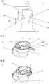
- FIG. 1 schematically a kitchen appliance 1 according to the invention with a connected gear adapter 10 and a kitchen machine component 30 mounted thereon in a proper orientation on a substrate U is shown standing.
- the kitchen machine component 30 could be, for example, a meat grinder or other shredding device, into or into which a respective food can be filled through a hopper 31 for processing by the kitchen machine component 30.
- the transmission adapter 10 is adapted to redirect a rotation caused by an electric motor of the food processor about a kitchen machine side (first) axis of rotation A 1 , namely to convert it into a rotation about a second axis of rotation A 2 , which in the present case is perpendicular to the first axis of rotation A 1 .
- the gearbox adapter comprises a ring-like housing portion 11 which is connected in the state shown to an adapter connection 20 (shown dashed in the figure) of the food processor or placed on it and thus surrounds the adapter connection.
- FIG. 2a shows an exemplary transmission adapter 10 according to an embodiment of the present invention in a perspective view.
- the transmission adapter comprises an annular housing portion 11 which is arranged around an inner region 12, and is adapted to deflect a food processor-side rotation about a rotation axis A 1 into a rotation with axis of rotation A 2 .
- the interior area 12 is configured to receive the adapter connection.
- the inner area 12 facing surface of the annular housing portion 11 has holding elements which are adapted to cooperate with corresponding (not shown) adapter connection holding elements and so to hold the gearbox connection to the adapter connection.
- the transmission adapter 10 further comprises a locking lever 13 with an operative portion 13a and an actuating arm 13b.
- the locking lever 13 is in an open position in which the gear adapter can be placed on (and thus connected to) a (suitable) adapter port of a food processor.
- the actuating arm 13b is substantially radially (relative to the axis of rotation A 1 ) from the annular housing portion 11 from.
- FIG. 2b is the transmission adapter 10 of FIG. 2a illustrated in a situation in which the locking lever has been brought into a closed position.
- the actuating arm 13b of the locking lever 13 abuts (substantially) on the housing of the gearbox adapter, in cross-section (along a plane perpendicular to Rotation axis A 1 ) present substantially tangentially to a circular outer edge of the annular housing portion 11th
- the lever Since the lever axis H in the FIGS. 2a, 2b illustrated embodiment (at least substantially) parallel to the axis of rotation A 1 of the inner region, the lever is pivotable between the open position and the closed position in a plane to which the axis of rotation A 1 is orthogonal; is the gearbox adapter - as in the FIG. 1 shown connected to a food processor in a proper orientation, the lever can thus be pivoted in a horizontal plane, and in the closed position (substantially tangential) on the housing of the transmission adapter actuating arm 13b extends (in its longitudinal direction) along said plane (which is pierced vertically by the central axis).
- the locking lever could, for example, be pivotable in a plane with the axis of rotation A 1 , that is, the lever axis extend perpendicular to the axis of rotation A 1 .
- the actuating arm In the closed position (preferably substantially tangential), the actuating arm could extend (in its longitudinal direction) in this case in particular to the knee 16 of the gearbox adapter, in which in the FIG. 1 shown orientation in the vertical direction.
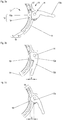
- FIG. 3a, 3b and 3c is a schematic plan view of a detail of a ring-like housing portion 11 of a transmission adapter 10 according to the invention shown.
- the ring-like housing portion 11 in this case has a wall 14, which - based on the inner region 12 - an inner housing wall 15 and an outer housing wall 16 includes, between which a gap 17 is formed.
- the transmission adapter 10 includes a detent mechanism 19 having a flexible member 18 having a boss 18a; this is adapted to penetrate into a corresponding recess on an adapter connection (not shown) and thus effect the latching.
- a detent mechanism 19 having a flexible member 18 having a boss 18a; this is adapted to penetrate into a corresponding recess on an adapter connection (not shown) and thus effect the latching.
- To the flexible element is pressed into the gap 17 (the flexible element yielding radially outward) when the gear adapter 10 is connected by means of a rotation to an adapter connection or detached from it (not shown).
- Pushing the flexible element 18 into the intermediate space 17 is preferably carried out by a (not shown) surface area on the adapter connection, which presses against the elevation 18a during the rotation of the transmission adapter until it penetrates into the recess (for example, snaps).
- the locking mechanism can be activated by means of the recess.
- the elevation 18a has a bevelled edge, which is adapted to cooperate with a (preferably also bevelled) edge of the recess of the adapter connection when unscrewing the transmission adapter, that the elevation 18a in turn in the open position of the lever mitels the rotation of the recess urged and the flexible member 18 so pressed into the gap 17, the locking mechanism is thus deactivated.
- the interior 12 facing surface of the flexible element is in the in FIG. 3a shown unloaded state substantially smoothly embedded in a flexible element 18 surrounding corresponding surface of the inner housing wall 15.
- the flexible element is protected by the inner housing wall 15 and the gear adapter therefore particularly durable.
- FIG. 3a is the pivotable about the lever axis H locking lever 13 of the transmission adapter shown in an open position in which the active portion 13a of the locking lever penetrates only minimally in the wall 14.
- the operative portion 13a is therefore spaced from the flexible member 18, so that this space is given for the said movement radially outward and the gear adapter 10 can be detached from the adapter connection or connected to him.
- the locking lever 13 In FIG. 3b the locking lever 13, however, is shown in a closed position. In this position, the effective portion 13a protrudes by a distance d in the wall 14 of the annular housing portion 11 and so presses against the flexible member 18 on the adapter port 20. As a result, the flexible member 18 are blocked to the outside, so that a detachment of the transmission adapter of an adapter connection of the food processor or a connection is prevented.
- Figure 3c shows an intermediate position of the locking lever 13 on the transmission adapter 10:
- the effective portion 13a of the locking lever projects by the distance D> d in the wall 14 of the annular housing portion 11 (ie even further than in the closed position), thus pressing the flexible member 18th radially inward.
- the flexible element 18 is slightly radially inward (in the example shown, even in the inner region, possibly in a gap between ring-like housing region and connected adapter connection), preferably against a restoring force acting radially outwards.
- the fixed flexible element in the closed position thus still has a corresponding range of motion (with a radial extent of at least Dd), so that the intermediate position is set by applying a minimum force.
- This embodiment has the advantage that in a closed position of the locking lever for opening only said restoring force must be overcome, which prevents unintentional pivoting of the locking lever and thus a (for example due to vibrations) unwanted detachment of the transmission adapter adapter adapter.
- An inventive transmission adapter 10 is provided for connection to a food processor 1 and adapted to redirect a rotation caused by an electric motor of the food processor. It comprises a housing with a ring-like housing region 11, which surrounds an inner region 12 for receiving a food processor-side adapter connection.
- the transmission adapter further has a latching mechanism 19 with a flexible element 18 for latching to the adapter connection and a closure lever 13 which fixes the flexible element in a closed position.
- a food processor 1 according to the invention comprises an adapter connection 20 and a transmission adapter 10 to be connected or connected to the adapter connection.
Landscapes
- Engineering & Computer Science (AREA)
- Mechanical Engineering (AREA)
- Food Science & Technology (AREA)
- Mechanical Operated Clutches (AREA)
Abstract
Description
- Die vorliegende Erfindung betrifft einen Getriebeadapter zum Anschluss an eine Küchenmaschine (also einen Küchenmaschinen-Getriebeadapter) und eine Küchenmaschine mit einem Getriebeadapter.
- Eine Vielzahl von Küchenmaschinenkomponenten, die zum Be- oder Verarbeiten von Lebensmitteln an eine geeignete Küchenmaschine angeschlossen werden können, umfasst jeweils mindestens ein rotierbares Element, das dazu eingerichtet ist, das jeweilige Lebensmittel zu rühren, zu passieren, zu zerkleinern oder dergleichen. Derartige rotierbare Elemente werden in der Regel durch einen Elektromotor der Küchenmaschine angetrieben, der eine Rotation einer Welle um eine Rotationsachse bewirkt: Mittels einer Kupplung kann diese küchenmaschinenseitige Rotation auf ein jeweiliges rotierbares Element einer angeschlossenen Küchenmaschinenkomponente übertragen werden.
- Ein Getriebeadapter kann dabei dazu dienen, eine derartige Übertragung auch in eine Rotation um eine andere Rotationsachse als die ursprüngliche zu ermöglichen, beispielsweise weil der Elektromotor in bestimmungsgemäßer Ausrichtung der Küchenmaschine eine Rotation um eine vertikal verlaufende erste Rotationsachse bewirkt, ein rotierbares Element der jeweiligen Komponente aber um eine horizontal verlaufende Rotationsachse rotieren soll. Herkömmlicherweise wird ein solcher Getriebeadapter an einen Adapteranschluss der Küchenmaschine angeschlossen und mittels einer Schraubverbindung fixiert.
- Eine derartige Fixierung hat den Nachteil, dass sich die Schraubverbindung durch Vibrationen im Betrieb der Küchenmaschine lösen kann. Zudem erhält ein Verwender keine klare Rückmeldung darüber, ob die Schraubverbindung ausreichend fest ist. Daher kann er beispielsweise eine über einen Getriebeadapter angeschlossene Komponente der Küchenmaschine in Betrieb nehmen, wenn der Getriebeadapter nur unzureichend an der Küchenmaschine fixiert ist. Der Getriebeadapter kann dadurch während des Betriebs von der Küchenmaschine abfallen, was sowohl die Gefahr von Verletzungen birgt, als auch zu Verschmutzungen des jeweiligen Lebensmittels und der Umgebung der Küchenmaschine führen kann.
- Die vorliegende Erfindung hat die Aufgabe, eine Technik bereitzustellen, mit der eine Umlenkung der Rotation einer Küchenmaschine unter Vermeidung der genannten Nachteile möglich ist.
- Ein erfindungsgemäßer Getriebeadapter ist dazu eingerichtet, an eine Küchenmaschine angeschlossen zu werden; dazu weist er ein Gehäuse mit einem ringartigen Gehäusebereich auf, der einen Innenbereich zur Aufnahme eines küchenmaschinenseitigen Adapteranschlusses umgibt.
- Eine vorgesehene Anschlussbewegung kann beispielsweise eine lineare und/oder eine Drehbewegung umfassen. Der Getriebeadapter kann zum Beispiel ein Gewinde und/oder mindestens ein Element eines Bajonettverschlusses umfassen, das dazu eingerichtet ist, mit mindestens einem passenden Element am Adapteranschluss zusammenzuwirken und so den Getriebeadapter am Adapteranschluss zu halten.
- Ein erfindungsgemäßer Getriebeadapter ist ferner dazu eingerichtet, im angeschlossenen Zustand eine von einem Elektromotor der Küchenmaschine bewirkte Rotation umzulenken, also eine küchenmaschinenseitige Rotation um eine erste Rotationsachse in eine Rotation um eine zweite, von der ersten verschiedene Rotationsachse umzuwandeln. Die Umlenkung kann eine Drehmoments-Übersetzung im Verhältnis 1:1 oder eine Übersetzung auf ein kleineres oder größeres Drehmoment umfassen.
- Zudem weist der erfindungsgemäße Getriebeadapter einen Rastmechanismus mit einem flexiblen Element auf, das dazu eingerichtet ist, mit dem Adapteranschluss zu verrasten. In einem derart verrasteten Zustand können z.B. mindestens ein Bereich des flexiblen Elements und ein Bereich des Adapteranschlusses ineinandergreifen und/oder aneinander anstoßen, und zum Lösen dieses Ineinandergreifens bzw. aneinander Anstoßens kann ein Nachgeben des flexiblen Elements erforderlich sein.
- Schließlich umfasst ein erfindungsgemäßer Getriebeadapter einen (verschwenkbaren) Verschlusshebel, der in einer Schließstellung das flexible Element fixiert.
- Als "fixiert" wird das flexible Element dabei in dieser Schrift verstanden, wenn es eine Bewegungsfreiheit des flexiblen Elements so weit einschränkt, dass ein Lösen und/oder Anschließen des Getriebeadapters an den Adapteranschluss (bzw. ein Lösen und/oder Eingehen der Rastverbindung) nicht möglich ist; dabei kann das flexible Element noch in einem begrenzten Spielraum nachgiebig sein, eine absolute Unbeweglichkeit des flexiblen Elements ist also auch in dessen "fixiertem Zustand" nicht zwingend erforderlich.
- Insbesondere kann durch das Fixieren ein Nachgeben des flexiblen Elements in mindestens eine Richtung verhindert und auf diese Weise ein Lösen des Getriebeadapters vom Adapteranschluss unterbunden werden.
- Aufgrund des Rastmechanismus' lässt sich ein erfindungsgemäßer Getriebeadapter in vorteilhafter Weise an einen Adapteranschluss einer Küchenmaschine anschließen, wobei die Fixierung des flexiblen Elements ein unbeabsichtigtes Ablösen, beispielsweise infolge von Vibrationen unterbindet. Zudem kann ein Verwender an der jeweiligen Hebelstellung des Verschlusshebels unmittelbar erkennen, ob die Verbindung von Getriebeadapter und Adapteranschluss hinreichend fest ist. Dadurch wird eine erhöhte Sicherheit der Küchenmaschine erreicht.
- Der Verschlusshebel ist vorzugsweise mindestens teilweise am ringartigen Gehäusebereich angeordnet, und zwar bevorzugt außen (also an der vom Innenbereich abgewandten Seite). Der Verschlusshebel wird somit vorzugsweise in dem Bereich eingesetzt, in dem der Adapteranschluss aufgenommen werden kann.
- Insbesondere ist vorzugsweise eine Hebelachse (um die der Verschlusshebel verschwenkbar ist) am ringartigen Gehäusebereich angeordnet. Sie kann beispielsweise im Wesentlichen senkrecht zur küchenmaschinenseitigen Rotationsachse verlaufen (die umzulenken der Getriebeadapter eingerichtet ist) verlaufen. In einer bestimmungsgemäßen Ausrichtung der Küchenmaschine, in der die zentrale Achse vorzugsweise vertikal angeordnet ist, kann der Verschlusshebel bei einer derartigen Ausführungsform von unten nach oben bzw. umgekehrt um die Hebelachse verschwenkt werden.
- Gemäß einer alternativen bevorzugten Ausführungsform eines erfindungsgemäßen Getriebeadapters verläuft die Hebelachse des Verschlusshebels im Wesentlichen parallel zur küchenmaschinenseitigen Rotationsachse. Ist diese Rotationsachse in einer bestimmungsgemäßen Ausrichtung der Küchenmaschine vertikal ausgerichtet, kann der Verschlusshebel bei einer solchen Ausführungsform also horizontal verschwenkt werden.
- Der ringartige Gehäusebereich ist vorzugsweise starr ausgebildet bzw. aus einem steifen Material, kann also nicht verengt werden. Vorzugsweise weist er an der dem Innenbereich zugewandten Oberfläche ein oder mehrere Halteelemente auf, die dazu eingerichtet sind, mit einer entsprechenden Oberfläche am Adapteranschluss zusammenzuwirken und so den Getriebeadapter, wenn er auf den Adapteranschluss aufgesetzt ist, daran zu halten.
- Vorteilhaft ist eine Ausführungsvariante, bei der mindestens der ringartige Gehäusebereich und/oder das flexible Element (im Wesentlichen) ganz oder teilweise aus Metall und/oder Kunststoff bestehen: Eine derartige Ausführung ist besonders stabil bzw. leicht.
- Bei einer vorteilhaften Ausführungsform eines erfindungsgemäßen Getriebeadapters ist das flexible Element am ringartigen Gehäusebereich angeordnet.
- Das flexible Element kann dazu eingerichtet sein, (vorzugsweise radial) in Richtung des Innenbereichs nachzugeben (sofern nichts anderes angegeben ist, bezieht sich die Angabe "radial" in dieser Schrift stets auf eine küchenmaschinenseitigen Rotationsachse, die umzulenken der Getriebeadapter eingerichtet ist). Der Verschlusshebel kann dann dazu eingerichtet sein, das flexible Element in der Schließstellung in eine entsprechende Ausnehmung in einem angeschlossenen Adapteranschluss hineinzudrücken und so zu fixieren.
- Gemäß einer bevorzugten Ausführungsvariante ist das flexible Element dazu eingerichtet, entgegen einer Rückstellkraft (vorzugsweise radial) nach außen (also vom Innenbereich weg) nachzugeben. Der Verschlusshebel ist dann vorzugsweise dazu eingerichtet, dieses Nachgeben in der Schließstellung zu unterbinden oder zumindest einzuschränken; das flexible Element ist dabei in der Schließstellung vorzugsweise entlastet, also nicht entgegen seiner Rückstellkraft ausgelenkt.
- Vorteilhaft ist eine Ausführungsform, bei der das flexible Element mindestens eine Erhebung und/oder Ausnehmung aufweist, die dazu eingerichtet ist, in der Schließstellung in eine jeweilige Ausnehmung am Adapteranschluss hineinzuragen bzw. eine Erhebung am Adapteranschluss aufzunehmen, wenn der Getriebeadapter an den Adapteranschluss angeschlossen ist.
- Gemäß einer bevorzugten Ausführungsform eines erfindungsgemäßen Getriebeadapters umfasst der Verschlusshebel einen Wirkabschnitt, der dazu eingerichtet ist, in der Schließstellung von außen in eine Wandung des ringartigen Gehäusebereichs hineinzuragen; vorzugsweise blockiert der Wirkabschnitt dabei innerhalb der Wandung eine Auslenkung des flexiblen Element und fixiert dieses damit. Ein Kontaktbereich von flexiblem Element und Verschlusshebel (bzw. dessen Wirkabschnitt) ist somit vorteilhaft von Gehäuse- bzw. Wandungskomponenten umgeben und auf diese Weise gegen Einwirkungen von außen (z.B. Verschmutzungen) geschützt.
- In einer Öffnungsstellung des Verschlusshebels, in welcher der Getriebeadapter auf den Adapteranschluss angeschlossen bzw. vom Adapteranschluss gelöst werden kann, ragt der Wirkabschnitt bei einer derartigen Ausführungsform vorzugsweise (im Vergleich zu anderen Stellungen des Verschlusshebels, insbesondere im Vergleich zur Schließstellung) weniger bzw. am wenigsten weit (oder sogar gar nicht) in die Wandung hinein.
- Vorteilhafterweise ist der Wirkabschnitt dazu eingerichtet ist, in einer Zwischenstellung zwischen einer Öffnungsstellung und der Schließstellung (vorzugsweise radial) weiter in die Wandung hineinzuragen als in der Schließstellung; der Wirkabschnitt kann dazu in einem Querschnitt (senkrecht zur Hebelachse) eine exzentrische Form aufweisen. Eine derartige Ausführungsform ermöglicht auf vorteilhafte Weise eine Sicherung des Verschlusshebels in der Schließstellung, weil zum Übergang in die Öffnungsstellung zunächst die Zwischenstellung überwunden und damit eine Mindestkraft aufgewendet werden muss.
- Vorteilhaft ist eine Ausführungsform, bei der das flexible Element als Teil des ringartigen Gehäusebereichs (bzw. dessen Wandung) mit einer dem Innenbereich zugewandten Oberfläche ausgebildet ist. In einem unbelasteten Zustand, in dem also keine Kraft auf das flexible Element ausgeübt wird, ist die dem Innenbereich zugewandte Oberfläche des flexiblen Elements vorzugsweise im Vergleich zu einer das flexible Element umgebenden (dem Innenbereich zugewandten) Oberfläche des ringartigen Gehäusebereichs im Wesentlichen radial nach außen versetzt angeordnet und/oder im Wesentlichen glatt in diese umgebende Oberfläche eingebettet (so dass sie also an ihrem Rand im Wesentlichen stufenlos in die umgebende Oberfläche des ringartigen Gehäusebereichs übergeht). Die dem Innenbereich zugewandte Oberfläche des flexiblen Elements bildet somit im unbelasteten Zustand an ihrem Rand vorzugsweise keine Stufe in den Innenbereich hinein aus. Dadurch wird das flexible Element beim Anschließen oder Lösen des Getriebeadapters höchstens durch geringe Kräfte angegriffen und ist somit besonders haltbar.
- Gemäß einer vorteilhaften Ausführungsform eines erfindungsgemäßen Getriebeadapters umfasst der Verschlusshebel einen Betätigungsarm (mit dem der Verschlusshebel zu betätigen ist, der also dazu eingerichtet ist, von einem Verwender zur Einstellung einer jeweiligen Stellung des Verschlusshebels (insbesondere der Schließstellung) betätigt zu werden).
- Vorzugsweise ist der Betätigungsarm an einem ersten Ende des Verschlusshebels angeordnet, das einem zweiten Ende des Verschlusshebels entgegengesetzt ist, wobei das zweite Ende einen (oben genannten) Wirkabschnitt umfasst; Betätigungsarm und Wirkabschnitt sind dabei vorzugsweise monolithisch ausgebildet, beispielsweise aus mindestens einem Kunststoff und/oder Metall.
- Der Betätigungsarm ist vorzugsweise dazu eingerichtet, in der Schließstellung des Verschlusshebels im Wesentlichen an dem Gehäuse des Getriebeadapters anzuliegen, bevorzugtermaßen im Wesentlichen tangential. In einer bestimmungsgemäßen Ausrichtung der Küchenmaschine kann der Betätigungsarm dabei in der Schließstellung (abhängig von einer Ausrichtung der Hebelachse) insbesondere z.B. in vertikaler Richtung oder in horizontaler Richtung an dem Gehäuse des Getriebeadapters im Wesentlichen anliegen.
- Durch das Anliegen des Betätigungsarmes in der Schließstellung wird zum einen die Schließstellung besonders gut sichtbar, zum andere ist sie haptisch leicht zu erkennen und insbesondere einfach einzustellen.
- Vorzugsweise ist der Betätigungsarm (alternativ oder zusätzlich) dazu eingerichtet, in einer Öffnungsstellung des Verschlusshebels im Wesentlichen radial vom Gehäuse des Getriebeadapters abzustehen. Die Öffnungsstellung ist dadurch für einen Verwender visuell und haptisch leicht zu erkennen und insbesondere gut einzustellen.
- Eine erfindungsgemäße Küchenmaschine umfasst einen Adapteranschluss und einen am Adapteranschluss angeschlossenen oder anzuschließenden Getriebeadapter gemäß einer der in dieser Schrift offenbarten Ausführungsformen.
- Der Adapteranschluss kann mindestens eine Erhebung und/oder mindestens eine Ausnehmung in seiner (radial) äußeren Oberfläche aufweisen, die dazu eingerichtet ist, zum Bewirken der Verrastung mit einem jeweils passenden Element am Getriebeadapter, insbesondere am flexiblen Element in eine Wirkverbindung zu treten, beispielsweise ein für ein Anschließen und/oder Lösen des Getriebeadapters erforderliches Verdrehen zu blockieren.
- Gemäß einer bevorzugten Ausführungsform einer erfindungsgemäßen Küchenmaschine ist der Getriebeadapter dazu eingerichtet, mit einer jeweiligen Drehbewegung (relativ zum Adapteranschluss) in den Adapteranschluss eingedreht bzw. aus diesem herausgedreht zu werden; insbesondere können Getriebeadapter und Adapteranschluss einen Bajonettanschluss ausbilden. Das flexible Element ist dabei vorzugsweise dazu eingerichtet, für ein Lösen und ein Anschließen des Getriebeadapters jeweils radial nach außen nachzugeben, und der Adapteranschluss weist vorteilhafterweise einen Oberflächenbereich auf, der dazu eingerichtet ist, in einer Öffnungsstellung des Verschlusshebels das flexible Element bei einem Eindrehen bzw. Ausdrehen des Getriebeadapters in bzw. aus dem Adapteranschluss nach radial außen zu drücken.
- Auf diese Weise kann der Rastmechanismus in Öffnungsstellung des Verschlusshebels besonders einfach, nämlich im Wege der Drehung aktiviert und deaktiviert werden.
- Im Folgenden werden bevorzugte Ausführungsbeispiele der Erfindung anhand von Zeichnungen näher erläutert. Es versteht sich, dass einzelne Elemente und Komponenten auch anders kombiniert werden können als dargestellt. Bezugszeichen für einander entsprechende Elemente sind figurenübergreifend verwendet und werden ggf. nicht für jede Figur neu beschrieben.
- Es zeigen schematisch:
- Figur 1:
- eine Küchenmaschine mit einem angeschlossenen Getriebeadapter gemäß einer Ausführungsform der vorliegenden Erfindung;
- Figur 2a:
- einen exemplarischen erfindungsgemäßen Getriebeadapter mit einem Verschlusshebel in Öffnungsstellung;
- Figur 2b:
- den in der
Figur 2a dargestellten Getriebeadapter mit dem Verschlusshebel in Schließstellung; - Figur 3a:
- eine schematische Draufsicht auf einen Verschlusshebel eines exemplarischen erfindungsgemäßen Getriebeadapters in Öffnungsstellung;
- Figur 3b:
- den Verschlusshebel gemäß
Figur 3a in Schließstellung; und - Figur 3c:
- den Verschlusshebel gemäß den
Figuren 3a und 3b in einer Zwischenstellung zwischen Öffnungs- und Schließstellung. - In
Figur 1 ist schematisch eine erfindungsgemäße Küchenmaschine 1 mit einem angeschlossenen Getriebeadapter 10 sowie einer daran montierten Küchenmaschinenkomponente 30 in einer bestimmungsgemäßen Ausrichtung auf einem Untergrund U stehend dargestellt. Die Küchenmaschinenkomponente 30 könnte beispielsweise ein Fleischwolf oder eine sonstige Zerkleinerungsvorrichtung sein, in den bzw. in die durch einen Einfülltrichter 31 ein jeweiliges Lebensmittel zur Bearbeitung durch die Küchenmaschinenkomponente 30 eingefüllt werden kann. - Der Getriebeadapter 10 ist dazu eingerichtet, eine von einem Elektromotor der Küchenmaschine bewirkte Rotation um eine küchenmaschinenseitige (erste) Rotationsachse A1 umzulenken, nämlich in eine Rotation um eine zweite Rotationsachse A2 umzuwandeln, die vorliegend senkrecht zur ersten Rotationsachse A1 verläuft.
- Der Getriebeadapter umfasst einen ringartigen Gehäusebereich 11, der im gezeigten Zustand an einen (in der Figur gestrichelt dargestellten) Adapteranschluss 20 der Küchenmaschine angeschlossen bzw. auf sie aufgesetzt ist und den Adapteranschluss somit umgibt.
-
Figur 2a zeigt einen exemplarischen Getriebeadapter 10 gemäß einer Ausführungsform der vorliegenden Erfindung in perspektivischer Ansicht. Der Getriebeadapter umfasst einen ringartigen Gehäusebereich 11, der um einen Innenbereich 12 herum angeordnet ist, und er ist dazu eingerichtet, eine küchenmaschinenseitige Rotation um eine Rotationsachse A1 in eine Rotation mit Rotationsachse A2 umzulenken. - Der Innenbereich 12 ist dazu eingerichtet, den Adapteranschluss aufzunehmen. Die dem Innenbereich 12 zugewandte Oberfläche des ringartigen Gehäusebereichs 11 weist Halteelemente auf, die dazu eingerichtet sind, mit entsprechenden (nicht dargestellten) Adapteranschluss-Halteelementen zusammenzuwirken und so den Getriebeanschluss am Adapteranschluss zu halten.
- Der Getriebeadapter 10 umfasst ferner einen Verschlusshebel 13 mit einem Wirkabschnitt 13a und einem Betätigungsarm 13b. In der in der Figur gezeigten Situation befindet sich der Verschlusshebel 13 in einer Öffnungsstellung, in welcher der Getriebeadapter auf einen (passenden) Adapteranschluss einer Küchenmaschine aufgesetzt (und damit an ihn angeschlossen) werden kann. In dieser Stellung steht der Betätigungsarm 13b im Wesentlichen radial (bezogen auf die Rotationsachse A1) vom ringartigen Gehäusebereich 11 ab.
- In
Figur 2b ist der Getriebeadapter 10 derFigur 2a in einer Situation dargestellt, in welcher der Verschlusshebel in eine Schließstellung gebracht wurde. In dieser Stellung liegt der Betätigungsarm 13b des Verschlusshebels 13 (im Wesentlichen) am Gehäuse des Getriebeadapters an, und zwar im Querschnitt (entlang einer Ebene senkrecht zur Rotationsachse A1) vorliegend im Wesentlichen tangential an einem kreisförmigen Außenrand des ringartigen Gehäusebereichs 11. - Da die Hebelachse H im in den
Figuren 2a, 2b dargestellten Ausführungsbeispiel (mindestens im Wesentlichen) parallel zur Rotationsachse A1 des Innenbereichs verläuft, ist der Hebel zwischen der Öffnungsstellung und der Schließstellung in einer Ebene verschwenkbar, zu der die Rotationsachse A1 orthogonal verläuft; ist der Getriebeadapter - wie in derFigur 1 gezeigt - an eine Küchenmaschine in einer bestimmungsgemäßen Ausrichtung angeschlossen, kann der Hebel somit in einer horizontalen Ebene verschwenkt werden, und der in der Schließstellung (im Wesentlichen tangential) am Gehäuse des Getriebeadapters anliegende Betätigungsarm 13b erstreckt sich (in seiner Längsrichtung) entlang der genannten Ebene (die von der zentralen Achse senkrecht durchstoßen wird). - Alternativ könnte der Verschlusshebel beispielsweise in einer Ebene mit der Rotationsachse A1 verschwenkbar sein, die Hebelachse also senkrecht zur Rotationsachse A1 verlaufen. Der in der Schließstellung (vorzugsweise im Wesentlichen tangential) anliegende Betätigungsarm könnte sich (in seiner Längsrichtung) in diesem Fall insbesondere zum Knie 16 des Getriebeadapters hin erstrecken, in der in der
Figur 1 gezeigten Ausrichtung also in vertikaler Richtung. - In den
Figuren 3a, 3b und 3c ist jeweils schematisch eine Draufsicht auf einen Ausschnitt eines ringartigen Gehäusebereichs 11 eines erfindungsgemäßen Getriebeadapters 10 gezeigt. Der ringartige Gehäusebereich 11 weist dabei eine Wandung 14 auf, die - bezogen auf den Innenbereich 12 - eine innere Gehäusewand 15 und eine äußere Gehäusewand 16 umfasst, zwischen denen ein Zwischenraum 17 ausgebildet ist. - Der Getriebeadapter 10 umfasst einen Rastmechanismus 19 mit einem flexiblen Element 18, das eine Erhebung 18a aufweist; diese ist dazu eingerichtet, in eine entsprechende Ausnehmung an einem (nicht gezeigten) Adapteranschluss einzudringen und so die Verrastung zu bewirken. Dazu
wird das flexible Element in den Zwischenraum 17 hineingedrückt (wobei das flexible Element radial nach außen nachgibt), wenn der Getriebeadapter 10 mittels einer Drehung an einen Adapteranschluss angeschlossen oder von ihm gelöst wird (nicht dargestellt). - Das Hineindrücken des flexiblen Elements 18 in den Zwischenraum 17 erfolgt vorzugsweise durch einen (nicht dargestellten) Oberflächenbereich am Adapteranschluss, der bei der Drehung des Getriebeadapters gegen die Erhebung 18a drückt, bis diese in die Ausnehmung eindringt (beispielsweise einschnappt). So kann der Rastmechanismus im Wege der Eindrehung aktiviert werden. Die Erhebung 18a weist einen angeschrägten Rand auf, der dazu eingerichtet ist, bei einem Herausdrehen des Getriebeadapters mit einem (vorzugsweise ebenfalls angeschrägten) Rand der Ausnehmung des Adapteranschluss so zusammenzuwirken, dass die Erhebung 18a in der Öffnungsstellung des Hebels wiederum mitels der Drehung aus der Ausnehmung gedrängt und das flexible Element 18 damit in den Zwischenraum 17 gedrückt, der Rastmechanismus also deaktiviert wird.
- Die dem Innenraum 12 zugewandte Oberfläche des flexiblen Element ist im in der
Figur 3a gezeigten unbelasteten Zustand im Wesentlichen glatt in eine das flexible Element 18 umgebende entsprechende Oberfläche der inneren Gehäusewand 15 eingebettet. Das flexible Element ist so durch die innere Gehäusewand 15 geschützt und der Getriebeadapter daher besonders haltbar. - In
Figur 3a ist der um die Hebelachse H verschwenkbare Verschlusshebel 13 des Getriebeadapters in einer Öffnungsstellung gezeigt, in welcher der Wirkabschnitt 13a des Verschlusshebels nur minimal in die Wandung 14 eindringt. - Der Wirkabschnitt 13a ist daher von dem flexiblen Element 18 beabstandet, so dass diesem Raum für die genannte Bewegung radial nach außen gegeben ist und der Getriebeadapter 10 vom Adapteranschluss gelöst bzw. an ihn angeschlossen werden kann werden kann.
- In
Figur 3b ist der Verschlusshebel 13 dagegen in einer Schließstellung gezeigt. In dieser Stellung ragt der Wirkabschnitt 13a um einen Abstand d in die Wandung 14 des ringartigen Gehäusebereichs 11 hinein und drückt so gegen das flexible Element 18 am Adapteranschluss 20. Dadurch wird das flexible Element 18 nach außen blockiert werden, so dass ein Ablösen des Getriebeadapters von einem Adapteranschluss der Küchenmaschine bzw. ein Anschließen unterbunden wird. -
Figur 3c zeigt eine Zwischenstellung des Verschlusshebels 13 am Getriebeadapter 10: In dieser Stellung ragt der Wirkabschnitt 13a des Verschlusshebels um den Abstand D > d in die Wandung 14 des ringartigen Gehäusebereichs 11 hinein (also sogar weiter als in der Schließstellung) und drückt so das flexible Element 18 radial nach innen. Das flexible Element 18 gibt dabei leicht radial nach (im gezeigten Beispiel sogar in den Innenbereich, ggf. in einen Zwischenraum zwischen ringartigem Gehäusebereich und angeschlossenem Adapteranschluss hinein), vorzugsweise entgegen einer radial nach außen wirkenden Rückstellkraft. In einem Zustand, in dem der Getriebeadapter an einen Adapteranschluss angeschlossen ist, hat das fixierte flexible Element in der Schließstellung somit noch einen entprechenden Bewegungsspielraum (mit einer radialen Ausdehnung von mindestens D-d), so dass die Zwischenstellung bei Anwendung einer Mindestkraft einzustellen ist. - Diese Ausführungsform hat den Vorteil, dass in einer Schließstellung des Verschlusshebels zum Öffnen erst die genannte Rückstellkraft überwunden werden muss, was ein unbeabsichtigtes Verschwenken des Verschlusshebels und somit ein (beispielsweise durch Vibrationen bedingtes) unerwünschtes Ablösen des Getriebeadapters vom Adapteranschluss verhindert.
- Ein erfindungsgemäßer Getriebeadapter 10 ist zum Anschluss an eine Küchenmaschine 1 vorgesehen und dazu eingerichtet, eine von einem Elektromotor der Küchenmaschine bewirkte Rotation umzulenken. Er umfasst ein Gehäuse mit einem ringartigen Gehäusebereich 11, der einen Innenbereich 12 zur Aufnahme eines küchenmaschinenseitigen Adapteranschlusses umgibt. Der Getriebeadapter weist ferner einen Rastmechanismus 19 mit einem flexiblen Element 18 zum Verrasten mit dem Adapteranschluss sowie einen Verschlusshebel 13 auf, der in einer Schließstellung das flexible Element fixiert.
- Eine erfindungsgemäße Küchenmaschine 1 umfasst einen Adapteranschluss 20 und einen an den Adapteranschluss anzuschließenden oder angeschlossenen Getriebeadapter 10.
-
- 1
- Küchenmaschine
- 10
- Getriebeadapter
- 11
- ringartiger Gehäusebereich
- 12
- Innenbereich
- 13
- Verschlusshebel
- 13a
- Wirkabschnitt
- 13b
- Betätigungsarm
- 14
- Wandung
- 15
- innere Gehäusewand
- 16
- äußere Gehäusewand
- 17
- Zwischenraum
- 18
- flexibles Element
- 18a
- Erhebung
- 19
- Rastmechanismus
- 20
- Anschlussadapter
- 30
- Küchenmaschinenkomponente
- 31
- Einfülltrichter
- A1
- küchenmaschinenseitige (erste) Rotationsachse
- A2
- komponentenseitige (zweite) Rotationsachse
- d
- Abstand, um den der Wirkabschnitt in Schließstellung des Verschlusshebels in die Wandung hineinragt
- D
- Abstand, um den der Wirkabschnitt in einer Zwischenstellung des Verschlusshebels in die Wandung hineinragt
- H
- Hebelachse
- U
- Untergrund
Claims (9)
- Getriebeadapter (10) zum Anschluss an eine Küchenmaschine, wobei der Getriebeadapter dazu eingerichtet ist, eine von einem Elektromotor der Küchenmaschine bewirkte Rotation umzulenken, und wobei der Getriebeadapter umfasst:- ein Gehäuse mit einem ringartigen Gehäusebereich (11), der einen Innenbereich (12) zur Aufnahme eines küchenmaschinenseitigen Adapteranschlusses umgibt;- einen Rastmechanismus (19) mit einem flexiblen Element (18) zum Verrasten mit dem Adapteranschluss und- einen Verschlusshebel (13), der dazu eingerichtet ist, in einer Schließstellung das flexible Element (17) zu fixieren.
- Getriebeadapter gemäß Anspruch 1, wobei der Verschlusshebel (13) mindestens teilweise außen am ringartigen Gehäusebereich (11) angeordnet ist.
- Getriebeadapter gemäß Anspruch 1 oder 2, wobei der Verschlusshebel (13) einen Wirkabschnitt (13a) umfasst, der dazu eingerichtet ist, in der Schließstellung von außen in eine Wandung (14) des ringartigen Gehäusebereichs (11) hineinzuragen.
- Getriebeadapter gemäß Anspruch 3, wobei der Wirkabschnitt (13a) dazu eingerichtet ist, in einer Zwischenstellung zwischen einer Öffnungsstellung und der Schließstellung radial weiter in die Wandung hineinzuragen als in der Schließstellung.
- Getriebeadapter gemäß einem der vorhergehenden Ansprüche, wobei das flexible Element (18)- dazu eingerichtet ist, in Richtung zum Innenbereich (12) hin nachzugeben und/oder- dazu eingerichtet ist, in Richtung vom Innenbereich (12) weg nachzugeben.
- Getriebeadapter gemäß einem der vorhergehenden Ansprüche, wobei der Verschlusshebel (13) einen Betätigungsarm (13b) aufweist, der dazu eingerichtet ist,- in der Schließstellung des Verschlusshebels im Wesentlichen an dem Gehäuse des Getriebeadapters (10) anzuliegen; und/oder- in einer Öffnungsstellung des Verschlusshebels im Wesentlichen radial vom ringartigen Gehäusebereich (11) abzustehen.
- Getriebeadapter gemäß einem der vorhergehenden Ansprüche, wobei mindestens der ringartige Gehäusebereich (11) und/oder das flexible Element (18) ganz oder teilweise aus Metall bestehen.
- Küchenmaschine (1) mit einem Adapteranschluss (20) und einem an den Adapteranschluss anzuschließenden oder angeschlossenen Getriebeadapter (10) gemäß einem der vorhergehenden Ansprüche.
- Küchenmaschine gemäß Anspruch 8, wobei der Getriebeadapter (10) dazu eingerichtet ist, mit einer jeweiligen Drehbewegung in den Adapteranschluss (20) eingedreht bzw. aus diesem herausgedreht zu werden, und wobei der Adapteranschluss einen Oberflächenbereich aufweist, der dazu eingerichtet ist, das flexible Element bei einem Eindrehen nach radial außen zu drücken.
Priority Applications (1)
| Application Number | Priority Date | Filing Date | Title |
|---|---|---|---|
| SI201730069T SI3292804T1 (sl) | 2016-08-26 | 2017-08-15 | Adapter gonila kuhinjskega aparata z zaklepno ročico |
Applications Claiming Priority (1)
| Application Number | Priority Date | Filing Date | Title |
|---|---|---|---|
| DE102016216095.8A DE102016216095A1 (de) | 2016-08-26 | 2016-08-26 | Küchenmaschinen-Getriebeadapter mit Verschlusshebel |
Publications (2)
| Publication Number | Publication Date |
|---|---|
| EP3292804A1 true EP3292804A1 (de) | 2018-03-14 |
| EP3292804B1 EP3292804B1 (de) | 2019-05-29 |
Family
ID=59631622
Family Applications (1)
| Application Number | Title | Priority Date | Filing Date |
|---|---|---|---|
| EP17186258.4A Active EP3292804B1 (de) | 2016-08-26 | 2017-08-15 | Küchenmaschinen-getriebeadapter mit verschlusshebel |
Country Status (3)
| Country | Link |
|---|---|
| EP (1) | EP3292804B1 (de) |
| DE (1) | DE102016216095A1 (de) |
| SI (1) | SI3292804T1 (de) |
Cited By (1)
| Publication number | Priority date | Publication date | Assignee | Title |
|---|---|---|---|---|
| EP4129132A1 (de) * | 2021-08-05 | 2023-02-08 | BSH Hausgeräte GmbH | Axialadapter für küchengerät |
Families Citing this family (1)
| Publication number | Priority date | Publication date | Assignee | Title |
|---|---|---|---|---|
| DE202023107312U1 (de) * | 2023-12-11 | 2025-03-13 | Keller Und Koop Gmbh | Mobiler Adapter für eine Küchenmaschine |
Citations (3)
| Publication number | Priority date | Publication date | Assignee | Title |
|---|---|---|---|---|
| FR2983054A1 (fr) * | 2011-11-28 | 2013-05-31 | Seb Sa | Accessoire de preparation d'aliments presentant une configuration de rangement |
| EP2777447A1 (de) * | 2013-03-15 | 2014-09-17 | Whirlpool Corporation | Küchenmaschinenmixeraufsatz |
| DE202016104138U1 (de) * | 2016-07-28 | 2016-08-09 | Lurch Ag | Küchenmaschine |
Family Cites Families (4)
| Publication number | Priority date | Publication date | Assignee | Title |
|---|---|---|---|---|
| FR851004A (fr) | 1938-03-12 | 1940-01-02 | Magneto Belge | Machine culinaire |
| DE1055773B (de) | 1953-04-24 | 1959-04-23 | Max Braun Fa | Getriebekopf fuer elektrisch betriebene Kuechenmaschinen |
| DE4016615C1 (de) | 1990-05-23 | 1991-12-19 | Messerschmidt, Wilfried, 7744 Koenigsfeld, De | |
| DE9115710U1 (de) | 1991-12-18 | 1992-03-19 | Bosch-Siemens Hausgeräte GmbH, 8000 München | Küchenmaschine, insbesondere für den Haushalt |
-
2016
- 2016-08-26 DE DE102016216095.8A patent/DE102016216095A1/de not_active Ceased
-
2017
- 2017-08-15 SI SI201730069T patent/SI3292804T1/sl unknown
- 2017-08-15 EP EP17186258.4A patent/EP3292804B1/de active Active
Patent Citations (3)
| Publication number | Priority date | Publication date | Assignee | Title |
|---|---|---|---|---|
| FR2983054A1 (fr) * | 2011-11-28 | 2013-05-31 | Seb Sa | Accessoire de preparation d'aliments presentant une configuration de rangement |
| EP2777447A1 (de) * | 2013-03-15 | 2014-09-17 | Whirlpool Corporation | Küchenmaschinenmixeraufsatz |
| DE202016104138U1 (de) * | 2016-07-28 | 2016-08-09 | Lurch Ag | Küchenmaschine |
Cited By (1)
| Publication number | Priority date | Publication date | Assignee | Title |
|---|---|---|---|---|
| EP4129132A1 (de) * | 2021-08-05 | 2023-02-08 | BSH Hausgeräte GmbH | Axialadapter für küchengerät |
Also Published As
| Publication number | Publication date |
|---|---|
| SI3292804T1 (sl) | 2019-08-30 |
| DE102016216095A1 (de) | 2018-03-01 |
| EP3292804B1 (de) | 2019-05-29 |
Similar Documents
| Publication | Publication Date | Title |
|---|---|---|
| DE69412880T2 (de) | Drehbetätigungseinrichtung für einen Leistungsschalter | |
| EP2101706B1 (de) | Lösbare anbringung eines zubehörs an einem operationstisch | |
| EP2934359B1 (de) | Instrumentenhalter | |
| EP2846951B1 (de) | Schnellspann-kupplung | |
| EP1323391A2 (de) | Verschlusseinrichtung zum Sichern eines Stabes in einem Aufnahmeteil insbesondere einer Polyaxial-Knochenschraube | |
| EP2853212B1 (de) | Chirurgisches Instrument | |
| DE102009006689A1 (de) | Chirurgisches Instrument | |
| WO2010121388A1 (de) | Befestigungsvorrichtung für chirurgische haltesysteme | |
| EP3261566B1 (de) | Knochenplatte und operationsset zum fixieren von knochenfragmenten | |
| EP3410965A1 (de) | Instrument zum führen eines stabs in eine implantataufnahme | |
| EP3292804B1 (de) | Küchenmaschinen-getriebeadapter mit verschlusshebel | |
| EP2848159A1 (de) | Griff | |
| EP1581084B1 (de) | Becheranordnung für eine mischzerkleinerungsvorrichtung | |
| EP3569116B1 (de) | Speisenzubereitungsvorrichtung mit lösbarem werkzeug | |
| EP2257245B1 (de) | Medizinisches implantat und kniegelenkendoprothese | |
| EP1831492A1 (de) | Scharniervorrichtung und verfahren zu deren betrieb | |
| EP3287054A1 (de) | Verbindungsvorrichtung zum ankuppeln einer aufsatzeinrichtung an eine küchenmaschine | |
| DE112010003875T5 (de) | Schaltschlossarmatur und Steuereinrichtung | |
| EP2918354A1 (de) | Pressaufsatz zum axialen Verpressen von Werkstücken | |
| EP4042958A1 (de) | Medizinische drehmomentbegrenzungsvorrichtung | |
| EP3864992A1 (de) | Einhand-schnellverschluss | |
| EP4119737B1 (de) | Rückhaltevorrichtung insbesondere für den wasserablauf von flachdächern | |
| EP4132332B1 (de) | Verstellbare gewürzmühle | |
| EP3503778B1 (de) | Küchenmaschine und verfahren zum betreiben einer küchenmaschine | |
| BE1026223B1 (de) | Elektrisches Steckverbinderteil und elektrisches Steckverbindungssystem mit Verriegelung |
Legal Events
| Date | Code | Title | Description |
|---|---|---|---|
| PUAI | Public reference made under article 153(3) epc to a published international application that has entered the european phase |
Free format text: ORIGINAL CODE: 0009012 |
|
| STAA | Information on the status of an ep patent application or granted ep patent |
Free format text: STATUS: THE APPLICATION HAS BEEN PUBLISHED |
|
| AK | Designated contracting states |
Kind code of ref document: A1 Designated state(s): AL AT BE BG CH CY CZ DE DK EE ES FI FR GB GR HR HU IE IS IT LI LT LU LV MC MK MT NL NO PL PT RO RS SE SI SK SM TR |
|
| AX | Request for extension of the european patent |
Extension state: BA ME |
|
| STAA | Information on the status of an ep patent application or granted ep patent |
Free format text: STATUS: REQUEST FOR EXAMINATION WAS MADE |
|
| 17P | Request for examination filed |
Effective date: 20180914 |
|
| RBV | Designated contracting states (corrected) |
Designated state(s): AL AT BE BG CH CY CZ DE DK EE ES FI FR GB GR HR HU IE IS IT LI LT LU LV MC MK MT NL NO PL PT RO RS SE SI SK SM TR |
|
| GRAP | Despatch of communication of intention to grant a patent |
Free format text: ORIGINAL CODE: EPIDOSNIGR1 |
|
| STAA | Information on the status of an ep patent application or granted ep patent |
Free format text: STATUS: GRANT OF PATENT IS INTENDED |
|
| RIC1 | Information provided on ipc code assigned before grant |
Ipc: A47J 43/06 20060101AFI20181218BHEP |
|
| INTG | Intention to grant announced |
Effective date: 20190116 |
|
| GRAS | Grant fee paid |
Free format text: ORIGINAL CODE: EPIDOSNIGR3 |
|
| GRAA | (expected) grant |
Free format text: ORIGINAL CODE: 0009210 |
|
| STAA | Information on the status of an ep patent application or granted ep patent |
Free format text: STATUS: THE PATENT HAS BEEN GRANTED |
|
| AK | Designated contracting states |
Kind code of ref document: B1 Designated state(s): AL AT BE BG CH CY CZ DE DK EE ES FI FR GB GR HR HU IE IS IT LI LT LU LV MC MK MT NL NO PL PT RO RS SE SI SK SM TR |
|
| REG | Reference to a national code |
Ref country code: GB Ref legal event code: FG4D Free format text: NOT ENGLISH |
|
| REG | Reference to a national code |
Ref country code: CH Ref legal event code: EP |
|
| REG | Reference to a national code |
Ref country code: AT Ref legal event code: REF Ref document number: 1137753 Country of ref document: AT Kind code of ref document: T Effective date: 20190615 |
|
| REG | Reference to a national code |
Ref country code: DE Ref legal event code: R096 Ref document number: 502017001427 Country of ref document: DE |
|
| REG | Reference to a national code |
Ref country code: IE Ref legal event code: FG4D Free format text: LANGUAGE OF EP DOCUMENT: GERMAN |
|
| REG | Reference to a national code |
Ref country code: NL Ref legal event code: MP Effective date: 20190529 |
|
| REG | Reference to a national code |
Ref country code: LT Ref legal event code: MG4D |
|
| PG25 | Lapsed in a contracting state [announced via postgrant information from national office to epo] |
Ref country code: AL Free format text: LAPSE BECAUSE OF FAILURE TO SUBMIT A TRANSLATION OF THE DESCRIPTION OR TO PAY THE FEE WITHIN THE PRESCRIBED TIME-LIMIT Effective date: 20190529 Ref country code: NO Free format text: LAPSE BECAUSE OF FAILURE TO SUBMIT A TRANSLATION OF THE DESCRIPTION OR TO PAY THE FEE WITHIN THE PRESCRIBED TIME-LIMIT Effective date: 20190829 Ref country code: PT Free format text: LAPSE BECAUSE OF FAILURE TO SUBMIT A TRANSLATION OF THE DESCRIPTION OR TO PAY THE FEE WITHIN THE PRESCRIBED TIME-LIMIT Effective date: 20190930 Ref country code: ES Free format text: LAPSE BECAUSE OF FAILURE TO SUBMIT A TRANSLATION OF THE DESCRIPTION OR TO PAY THE FEE WITHIN THE PRESCRIBED TIME-LIMIT Effective date: 20190529 Ref country code: HR Free format text: LAPSE BECAUSE OF FAILURE TO SUBMIT A TRANSLATION OF THE DESCRIPTION OR TO PAY THE FEE WITHIN THE PRESCRIBED TIME-LIMIT Effective date: 20190529 Ref country code: LT Free format text: LAPSE BECAUSE OF FAILURE TO SUBMIT A TRANSLATION OF THE DESCRIPTION OR TO PAY THE FEE WITHIN THE PRESCRIBED TIME-LIMIT Effective date: 20190529 Ref country code: SE Free format text: LAPSE BECAUSE OF FAILURE TO SUBMIT A TRANSLATION OF THE DESCRIPTION OR TO PAY THE FEE WITHIN THE PRESCRIBED TIME-LIMIT Effective date: 20190529 Ref country code: FI Free format text: LAPSE BECAUSE OF FAILURE TO SUBMIT A TRANSLATION OF THE DESCRIPTION OR TO PAY THE FEE WITHIN THE PRESCRIBED TIME-LIMIT Effective date: 20190529 |
|
| PG25 | Lapsed in a contracting state [announced via postgrant information from national office to epo] |
Ref country code: LV Free format text: LAPSE BECAUSE OF FAILURE TO SUBMIT A TRANSLATION OF THE DESCRIPTION OR TO PAY THE FEE WITHIN THE PRESCRIBED TIME-LIMIT Effective date: 20190529 Ref country code: GR Free format text: LAPSE BECAUSE OF FAILURE TO SUBMIT A TRANSLATION OF THE DESCRIPTION OR TO PAY THE FEE WITHIN THE PRESCRIBED TIME-LIMIT Effective date: 20190830 Ref country code: RS Free format text: LAPSE BECAUSE OF FAILURE TO SUBMIT A TRANSLATION OF THE DESCRIPTION OR TO PAY THE FEE WITHIN THE PRESCRIBED TIME-LIMIT Effective date: 20190529 Ref country code: BG Free format text: LAPSE BECAUSE OF FAILURE TO SUBMIT A TRANSLATION OF THE DESCRIPTION OR TO PAY THE FEE WITHIN THE PRESCRIBED TIME-LIMIT Effective date: 20190829 |
|
| PG25 | Lapsed in a contracting state [announced via postgrant information from national office to epo] |
Ref country code: CZ Free format text: LAPSE BECAUSE OF FAILURE TO SUBMIT A TRANSLATION OF THE DESCRIPTION OR TO PAY THE FEE WITHIN THE PRESCRIBED TIME-LIMIT Effective date: 20190529 Ref country code: SK Free format text: LAPSE BECAUSE OF FAILURE TO SUBMIT A TRANSLATION OF THE DESCRIPTION OR TO PAY THE FEE WITHIN THE PRESCRIBED TIME-LIMIT Effective date: 20190529 Ref country code: EE Free format text: LAPSE BECAUSE OF FAILURE TO SUBMIT A TRANSLATION OF THE DESCRIPTION OR TO PAY THE FEE WITHIN THE PRESCRIBED TIME-LIMIT Effective date: 20190529 Ref country code: DK Free format text: LAPSE BECAUSE OF FAILURE TO SUBMIT A TRANSLATION OF THE DESCRIPTION OR TO PAY THE FEE WITHIN THE PRESCRIBED TIME-LIMIT Effective date: 20190529 Ref country code: NL Free format text: LAPSE BECAUSE OF FAILURE TO SUBMIT A TRANSLATION OF THE DESCRIPTION OR TO PAY THE FEE WITHIN THE PRESCRIBED TIME-LIMIT Effective date: 20190529 Ref country code: RO Free format text: LAPSE BECAUSE OF FAILURE TO SUBMIT A TRANSLATION OF THE DESCRIPTION OR TO PAY THE FEE WITHIN THE PRESCRIBED TIME-LIMIT Effective date: 20190529 |
|
| PG25 | Lapsed in a contracting state [announced via postgrant information from national office to epo] |
Ref country code: IT Free format text: LAPSE BECAUSE OF FAILURE TO SUBMIT A TRANSLATION OF THE DESCRIPTION OR TO PAY THE FEE WITHIN THE PRESCRIBED TIME-LIMIT Effective date: 20190529 Ref country code: SM Free format text: LAPSE BECAUSE OF FAILURE TO SUBMIT A TRANSLATION OF THE DESCRIPTION OR TO PAY THE FEE WITHIN THE PRESCRIBED TIME-LIMIT Effective date: 20190529 |
|
| REG | Reference to a national code |
Ref country code: DE Ref legal event code: R097 Ref document number: 502017001427 Country of ref document: DE |
|
| PG25 | Lapsed in a contracting state [announced via postgrant information from national office to epo] |
Ref country code: TR Free format text: LAPSE BECAUSE OF FAILURE TO SUBMIT A TRANSLATION OF THE DESCRIPTION OR TO PAY THE FEE WITHIN THE PRESCRIBED TIME-LIMIT Effective date: 20190529 |
|
| PLBE | No opposition filed within time limit |
Free format text: ORIGINAL CODE: 0009261 |
|
| STAA | Information on the status of an ep patent application or granted ep patent |
Free format text: STATUS: NO OPPOSITION FILED WITHIN TIME LIMIT |
|
| PG25 | Lapsed in a contracting state [announced via postgrant information from national office to epo] |
Ref country code: PL Free format text: LAPSE BECAUSE OF FAILURE TO SUBMIT A TRANSLATION OF THE DESCRIPTION OR TO PAY THE FEE WITHIN THE PRESCRIBED TIME-LIMIT Effective date: 20190529 |
|
| 26N | No opposition filed |
Effective date: 20200303 |
|
| PG25 | Lapsed in a contracting state [announced via postgrant information from national office to epo] |
Ref country code: MC Free format text: LAPSE BECAUSE OF FAILURE TO SUBMIT A TRANSLATION OF THE DESCRIPTION OR TO PAY THE FEE WITHIN THE PRESCRIBED TIME-LIMIT Effective date: 20190529 Ref country code: LU Free format text: LAPSE BECAUSE OF NON-PAYMENT OF DUE FEES Effective date: 20190815 |
|
| REG | Reference to a national code |
Ref country code: BE Ref legal event code: MM Effective date: 20190831 |
|
| PG25 | Lapsed in a contracting state [announced via postgrant information from national office to epo] |
Ref country code: IE Free format text: LAPSE BECAUSE OF NON-PAYMENT OF DUE FEES Effective date: 20190815 |
|
| PG25 | Lapsed in a contracting state [announced via postgrant information from national office to epo] |
Ref country code: BE Free format text: LAPSE BECAUSE OF NON-PAYMENT OF DUE FEES Effective date: 20190831 |
|
| REG | Reference to a national code |
Ref country code: CH Ref legal event code: PL |
|
| PG25 | Lapsed in a contracting state [announced via postgrant information from national office to epo] |
Ref country code: LI Free format text: LAPSE BECAUSE OF NON-PAYMENT OF DUE FEES Effective date: 20200831 Ref country code: CH Free format text: LAPSE BECAUSE OF NON-PAYMENT OF DUE FEES Effective date: 20200831 |
|
| PG25 | Lapsed in a contracting state [announced via postgrant information from national office to epo] |
Ref country code: CY Free format text: LAPSE BECAUSE OF FAILURE TO SUBMIT A TRANSLATION OF THE DESCRIPTION OR TO PAY THE FEE WITHIN THE PRESCRIBED TIME-LIMIT Effective date: 20190529 |
|
| PG25 | Lapsed in a contracting state [announced via postgrant information from national office to epo] |
Ref country code: IS Free format text: LAPSE BECAUSE OF FAILURE TO SUBMIT A TRANSLATION OF THE DESCRIPTION OR TO PAY THE FEE WITHIN THE PRESCRIBED TIME-LIMIT Effective date: 20190929 |
|
| PG25 | Lapsed in a contracting state [announced via postgrant information from national office to epo] |
Ref country code: HU Free format text: LAPSE BECAUSE OF FAILURE TO SUBMIT A TRANSLATION OF THE DESCRIPTION OR TO PAY THE FEE WITHIN THE PRESCRIBED TIME-LIMIT; INVALID AB INITIO Effective date: 20170815 Ref country code: MT Free format text: LAPSE BECAUSE OF FAILURE TO SUBMIT A TRANSLATION OF THE DESCRIPTION OR TO PAY THE FEE WITHIN THE PRESCRIBED TIME-LIMIT Effective date: 20190529 |
|
| GBPC | Gb: european patent ceased through non-payment of renewal fee |
Effective date: 20210815 |
|
| PG25 | Lapsed in a contracting state [announced via postgrant information from national office to epo] |
Ref country code: MK Free format text: LAPSE BECAUSE OF FAILURE TO SUBMIT A TRANSLATION OF THE DESCRIPTION OR TO PAY THE FEE WITHIN THE PRESCRIBED TIME-LIMIT Effective date: 20190529 |
|
| PG25 | Lapsed in a contracting state [announced via postgrant information from national office to epo] |
Ref country code: GB Free format text: LAPSE BECAUSE OF NON-PAYMENT OF DUE FEES Effective date: 20210815 |
|
| REG | Reference to a national code |
Ref country code: AT Ref legal event code: MM01 Ref document number: 1137753 Country of ref document: AT Kind code of ref document: T Effective date: 20220815 |
|
| PG25 | Lapsed in a contracting state [announced via postgrant information from national office to epo] |
Ref country code: AT Free format text: LAPSE BECAUSE OF NON-PAYMENT OF DUE FEES Effective date: 20220815 |
|
| PGFP | Annual fee paid to national office [announced via postgrant information from national office to epo] |
Ref country code: DE Payment date: 20250831 Year of fee payment: 9 |
|
| PGFP | Annual fee paid to national office [announced via postgrant information from national office to epo] |
Ref country code: FR Payment date: 20250821 Year of fee payment: 9 |
|
| PGFP | Annual fee paid to national office [announced via postgrant information from national office to epo] |
Ref country code: SI Payment date: 20250801 Year of fee payment: 9 |