EP3292793A1 - Modular seating furniture - Google Patents
Modular seating furniture Download PDFInfo
- Publication number
- EP3292793A1 EP3292793A1 EP16188302.0A EP16188302A EP3292793A1 EP 3292793 A1 EP3292793 A1 EP 3292793A1 EP 16188302 A EP16188302 A EP 16188302A EP 3292793 A1 EP3292793 A1 EP 3292793A1
- Authority
- EP
- European Patent Office
- Prior art keywords
- connector
- seat
- modular
- seating
- recesses
- Prior art date
- Legal status (The legal status is an assumption and is not a legal conclusion. Google has not performed a legal analysis and makes no representation as to the accuracy of the status listed.)
- Granted
Links
Images


Classifications
-
- A—HUMAN NECESSITIES
- A47—FURNITURE; DOMESTIC ARTICLES OR APPLIANCES; COFFEE MILLS; SPICE MILLS; SUCTION CLEANERS IN GENERAL
- A47C—CHAIRS; SOFAS; BEDS
- A47C13/00—Convertible chairs, stools or benches
- A47C13/005—Modular seating
-
- A—HUMAN NECESSITIES
- A47—FURNITURE; DOMESTIC ARTICLES OR APPLIANCES; COFFEE MILLS; SPICE MILLS; SUCTION CLEANERS IN GENERAL
- A47C—CHAIRS; SOFAS; BEDS
- A47C4/00—Foldable, collapsible or dismountable chairs
- A47C4/02—Dismountable chairs
- A47C4/028—Upholstered chairs, e.g. metal, plastic or wooden chairs
Definitions
- the invention relates to a chair with a plurality of seating furniture elements which are connected to each other by means of connector units and separable from each other.
- the chair is in particular a sofa, an armchair or a chaise longue.
- the seating furniture elements are in particular a seat part, a backrest and an armrest.
- Seating furniture with a plurality of seating furniture elements are known from the prior art, which are connectable to one another by means of connector units using tools and separable from each other.
- the invention has for its object to provide a modular seating whose seating furniture elements in a particularly simple manner can be assembled, disassembled and can be combined with other seating furniture elements to form another seat.
- the invention relates to a modular seating furniture having a first seating furniture element with a plurality of connector recesses, a second seating furniture element with a plurality of connector recesses and a connector unit for tool-free joining of the seating furniture elements.
- the connector unit comprises a base element forming a foot of the seat, a first connector pin opposite the foot element and a second connector pin opposite the foot element. In the assembled position of the chair, the first connector pin is inserted into a connector recess of the first seat furniture element and the second connector pin is inserted into a connector recess of the second seat furniture element.
- the invention furthermore relates to a connector unit for tool-free joining of two seat furniture elements to form a modular seat with a base element forming a foot of the seat, a first connector pin opposite the foot element and a second connector pin opposite the foot element.
- the connector pins are formed and arranged such that, in the assembled position of the chair, the first connector pin is inserted into a connector recess of the first seat furniture element and the second connector pin is inserted into a connector recess of the second seat furniture element.
- the invention further relates to a seating furniture element for a modular seating furniture having a bottom surface in which a plurality of connector recesses are arranged side by side in two rows extending over the entire length of the seating furniture element, wherein the connector recesses within the respective row are at a constant first distance from each other and the Connector recesses of the first row are arranged at the same first distance from the connector recesses of the second row.
- the new connector unit is a seating element connector unit and configured such that the seating elements can be tool-less connected, separated, and reconnected to each other or to other seating elements to construct another chair. Due to the flexible connector unit, the seating furniture can be very easily set up and dismantled by the end user at home. In the same simple manner but can also by another relative arrangement of the seating furniture elements to each other, an exchange of a part of the seating furniture elements, an addition of seating furniture elements or the elimination of part of the seating furniture a chair with a different geometry and other properties by the end user without special technical knowledge or skills are assembled.
- the new modular seating thus adapts ideally to long-term changes in requirements such as: B. due to a move or the redesign of a room. But there are also short-term changes easily possible, such as the extension of a sofa for a common evening with friends TV.
- the fixed and detachable connection between the seating furniture elements thus takes place essentially by inserting at least one connector pin of the connector unit into a corresponding connector recess of the first seat furniture element and the corresponding insertion of the second connector pin into a connector recess of the second seat furniture element.
- the seating furniture elements are connected together and at the same time ensures that the also present on the connector unit foot element can provide the supporting function of the foot of the chair and is located at the same height as the other feet of the chair.
- the connector units thus have a dual function, namely the joining of the seating furniture elements together and providing the feet of the chair.
- the connector units can be inserted with play into the connector recesses. This game allows the user to use the connector units without tools and without effort insert into the connector recesses and pull out of these. This results in a modular plug-in modular system with which comparatively complex seating furniture can be assembled and disassembled in just a few minutes.
- the connector units may each comprise a connector plate having a first side and an opposite second side, wherein the foot member is disposed on the first side and the connector pins are disposed on the second side.
- the connector plate thus has a connective effect in two respects. It connects the connector pins with each other so that the seat furniture members are connected to each other via the connector pins inserted into the connector recesses and the connector plate connecting the connector pins. At the same time, the connector plate also connects the connector pins to the foot member.
- the connector pins may have a circular cross section and an unprofiled surface. Accordingly, the connector recesses have a circular cross-section. Such holes can be particularly easy to bring into the seating furniture elements.
- the insertion of the connector pin in the circular holes is very simple. Since it is a tool-free assembly and disassembly, the surfaces of the connector pin and the connector recesses may be formed unprofiled. So they have in particular no thread.
- the connector pins and the connector recesses may be cylindrical or conical.
- the connector pins taper toward their free end, and the connector recesses have their largest diameter at the beginning of the recess.
- the connector pins can be particularly easily inserted into the connector recesses, without requiring an exact positioning of the connector unit to the seating furniture elements.
- a self-centering effect then occurs due to the coordinated conicity.
- the connector pins and the connector recesses may have a diameter or edge length of at least 10 mm.
- the diameter or the edge length is at least 15 mm, at least 20 mm or at least 25 mm.
- the maximum diameter or edge length is about 100 mm, about 80 mm, about 60 mm or about 40 mm. The diameter or the edge length is thus chosen so that the connector pin has the desired stability and is not in danger of breaking off.
- the connector pins may also have a rectangular, square, polygonal or elliptical cross section.
- the cross section is then matched to the cross section of the connector recess, so that the insertion of the connector pin into the respective connector recess is easily possible.
- the connector pins are always inserted independently of the direction into the corresponding connector recess.
- a specific mounting direction is specified. This may be useful to prevent unwanted incorrect assembly of the connector units.
- the connector unit has at least two connector pins. It can also have three, four, five, six, seven, eight, nine, ten or more connector pins. For geometric reasons, an integer number of connector pins is preferred. With four connector pin can be achieved particularly good results.
- the connector recesses may be arranged side by side in two different directions of the respective seating furniture element, in particular the width and the depth of the seating furniture element.
- the connector units can be attached to the seating furniture elements in two different positions or to fulfill two different functions.
- One position is the connection position. In this is at least one of the connector pin in a Verbind LucassEnglishung the first seat furniture element and at least one other connector pin in a recess of the second seat furniture element. But there is also a non-connecting position in which the connector unit only provides the foot function for the seating. This particularly concerns the areas of the seating furniture element to which no other seating furniture elements adjoin.
- the connector pins are thus used only in VerbehmerausEnglishisme a seating furniture element. They can be arranged offset inwardly so seen in the width and depth of the seating furniture element that the connector units is not or only slightly visible.
- the connector pins may be spaced a first distance apart and the connector recesses also spaced apart from one another by the first distance. Through this uniform spacing enables the universal use of the connector units in different places of the chair. A wrong operation is excluded.
- the connecting recesses may be arranged in the edge region of the underside of the respective seating furniture element.
- the bottom of the seating furniture element is thus used for connection with other seating furniture elements. This is advantageous because the underside of the seating furniture element is not visible and thus no visually disturbing impression is created by the Verbinderausappelisme.
- the arrangement of the connector recesses in the edge region means that the connector units have compact outer dimensions and provide the desired connection effect in the edge region.
- the connector recesses are arranged side by side in two rows extending over the entire length of the seating furniture element.
- This has the advantage that a high degree of variation is achieved by not only the corner regions or the ends of the seating furniture elements can be connected to each other, but also their central areas. But it is also possible to provide the VerbinderausEnglishept only in the corner areas or at the ends of the seating furniture elements. It is also possible to provide the connector recesses in the corner areas or at the ends of the seating furniture elements and in the central areas - but not in between.
- the connector recesses may be disposed within the respective row at a constant first distance from each other and the connector recesses of the first row may be located at the same first distance from the connector recesses of the second row. This ensures that a wrong insertion of a connector unit excluded and this can be used anywhere on the respective seating furniture element.
- the connector recesses in the underside of the seat furniture element can in particular consist of wood, plastic, metal or another material which is suitable for introducing the connector bores formed in particular as bores into the material.
- the seating so a base, in which the holes are introduced.
- the connector recesses can also z. B. are formed by a casting of metal or a plastic injection molded part.
- the main body can extend over the entire underside. However, it can have a central depression if the connector recesses are arranged only in the edge region. At its other upwardly facing side of the main body is closed and in particular with a cushioning material, eg. As a fabric or leather related foam connected. This padding then forms the actual seat or the backrest or armrest. For the backrest or armrest, the cushioning material can also be reinforced.
- the seating can also be designed without upholstery. An example of this is a seat.
- the first seating furniture element may be a seat part and the second seating furniture element may be a backrest or an armrest.
- Various combinations of these three basic elements make it possible to build many different types of seating. Examples include a corner sofa or a vis-à-vis sofa with 90 ° offset seating surfaces. In the seating furniture but it can also be another attachment for the seating, so z.
- the connector unit is in particular made of metal. But it could also consist of another material, which has the required strength and rigidity. So would be suitable, for example, plastic or wood.
- the seating furniture may be a sofa, an armchair, a bench or a chaise longue. But it is also possible that the seating is a reclining furniture - so in particular a bed - is. Even with such a reclining furniture, the new connector unit can be used to create different lengths and widths as well as a headboard, footboard, side shelves, etc. to order.
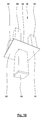
- Fig. 1 shows a first exemplary embodiment of a new modular chair 1 from above.
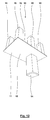
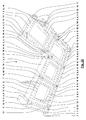
- Fig. 2 shows this chair 1 in a view from below.
- the modular seating 1 has a plurality of seating furniture elements 2 which are connected to each other.
- the modular seating 1 as a seating furniture elements 2, two seat parts 3, two back parts 4 and three armrests 5 on.
- Fig. 1 one recognizes further a part of the feet 6 of the modular chair. 1
- each of the seating furniture elements 2 has a plurality of connector recesses 7.
- the connector recesses 7 are arranged side by side in two different directions of the respective seat furniture element 2, namely the width and the depth of the seat furniture element 2.
- the connector recesses 7 are arranged in an edge region 8 of the underside 9 of the respective seating furniture element 2.
- the connector recesses 7 are arranged at a constant distance from each other in the two directions. They extend substantially over the entire edge region 8 of the underside 9 of the respective seating furniture element 2. In the present case, they are arranged there in two rows next to one another. But it is also possible that they are arranged only in a row or in more than two rows.
- the seating furniture elements 2 are connected to each other by connector units 10.
- connector units 10 are formed differently. These different embodiments will be further described with reference to the following drawings. But it is also possible that with only one design of the connector unit 10 all connections between the seating furniture elements 2 are made.
- Each of the connector units 10 has a connector plate 11 having a first side 12 and an opposite second side 13. On the first side 12, a foot member 14 is arranged. This foot member 14 forms one of the feet 6 of the chair. 1
- Fig. 3-18 For a more detailed construction of the connector unit 10 is now on the Fig. 3-18 referenced, in each of which two views of various exemplary embodiments of the connector unit 10 are shown.
- a plurality of connector pins 15 are arranged on the opposite second side 13.
- the connector pins 15 are arranged at the same distance as the connector recesses 7. They correspond with the connector recesses 7 such that they can be inserted into them. This is done without tools and preferably with play, so that the seating furniture elements 2 can be very easily and quickly connected to each other by means of the connector units 10 and separated from each other.
- the connector units 10 are in contact with two seating furniture elements 2 and thus connect them to one another.
- the seating furniture elements 2 are based on the connector plate 11 and the foot member 14 on the floor.
- the connector units 10 can be arranged according to the grid dimension of the connector recesses 7 at different locations along the edge regions 8 of the seating furniture elements 2. As long as the stability is not endangered, so the connector units 10 So also be easily seen in the depth of the chair 1 further inside, so that the feet 6 are barely visible or not at all. This results in a quasi hovering impression of the chair 1. It is also possible, in the depth of the chair 1 seen more connector units 10 between. This is particularly useful when the respective seating furniture element 2 has a comparatively large depth.
- the four connector pin 15 has a circular cross-section.
- the foot member 14 is arranged centrally.
- connector unit 10 At the in Fig. 5 and 6 shown connector unit 10, six connector pin 15 are present. These have a circular cross-section.
- the foot member 14 is arranged off-center.
- connector unit 10 has only two connector pin 15. These have a circular cross-section.
- connector unit 10 has four connector pin 15. These have a square cross-section.
- connector unit 10 has six connector pin 15. These have a circular cross-section.
- the foot member 14 is arranged off-center.
- connector unit 10 has only two connector pin 15. These have a square cross-section.
- connector unit 10 has eight connector pin 15. These have a circular cross-section.
- connector unit 10 has eight connector pin 15. These have a square cross-section.
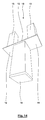
- Fig. 19 and 20 show another configuration example of the modular chair 1.
- a vis-à-vis arrangement of a sofa was also assembled, in contrast to Fig. 1 . 2 between the two seat parts 3 two armrests 5 are arranged.
- the back parts 4 move further away from each other.
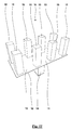
- Fig. 21 and 22 is a further configuration example of the modular chair 1 shown.
- it is a corner sofa with a seat extended to a lying surface.
- the connector units 10 can also be arranged at those locations on the underside 9 of the seating furniture elements 2, to which no further seating furniture element 2 adjoins (see upper right area in FIG Fig. 22 ).
- the two connector units 10 shown there thus fulfill no connection function, but only the function of forming a foot 6 of the chair 1 by the foot members 14th
Abstract
Ein modulares Sitzmöbel (1) weist ein erstes Sitzmöbelelement (2) mit einer Mehrzahl von Verbinderausnehmungen (7), ein zweites Sitzmöbelelement (2) mit einer Mehrzahl von Verbinderausnehmungen (7) und eine Verbindereinheit (10) zum werkzeuglosen Verbinden der Sitzmöbelelemente (2) auf. Die Verbindereinheit weist ein einen Fuß (6) des Sitzmöbels (1) bildendendes Fußelement (14), einen dem Fußelement (14) gegenüberliegenden ersten Verbinderzapfen (15) und einen dem Fußelement (14) gegenüberliegenden zweiten Verbinderzapfen (15) auf. In der montierten Stellung des Sitzmöbels (1) ist der erste Verbinderzapfen (15) in eine Verbinderausnehmung (7) des ersten Sitzmöbelelements (2) und der zweite Verbinderzapfen (15) in eine Verbinderausnehmung (7) des zweiten Sitzmöbelelements (2) eingesetzt.A modular seat (1) comprises a first seat furniture element (2) with a plurality of connector recesses (7), a second seat furniture element (2) with a plurality of connector recesses (7) and a connector unit (10) for tool-free connection of the seat furniture elements (2) on. The connector unit comprises a foot element (14) forming a foot (6) of the seat (1), a first connector pin (15) opposite the foot element (14) and a second connector pin (15) opposite the foot element (14). In the mounted position of the chair (1), the first connector pin (15) is inserted into a connector recess (7) of the first seat furniture member (2) and the second connector pin (15) is inserted into a connector recess (7) of the second seat furniture member (2).
Description
Die Erfindung betrifft ein Sitzmöbel mit einer Mehrzahl von Sitzmöbelelementen, die mittels Verbindereinheiten miteinander verbindbar und voneinander trennbar sind.The invention relates to a chair with a plurality of seating furniture elements which are connected to each other by means of connector units and separable from each other.
Bei dem Sitzmöbel handelt es sich insbesondere um ein Sofa, einen Sessel oder eine Chaiselongue. Die Sitzmöbelelemente sind dabei insbesondere ein Sitzteil, ein Rückenteil und eine Armlehne.The chair is in particular a sofa, an armchair or a chaise longue. The seating furniture elements are in particular a seat part, a backrest and an armrest.
Aus dem Stand der Technik sind Sitzmöbel mit einer Mehrzahl von Sitzmöbelelementen bekannt, die mittels Verbindereinheiten unter Verwendung von Werkzeugen miteinander verbindbar und voneinander trennbar sind.Seating furniture with a plurality of seating furniture elements are known from the prior art, which are connectable to one another by means of connector units using tools and separable from each other.
Der Erfindung liegt die Aufgabe zugrunde, ein modulares Sitzmöbel bereitzustellen, dessen Sitzmöbelelemente in besonders einfacher Weise zusammenbaubar, auseinanderbaubar und zur Bildung eines anderen Sitzmöbels mit anderen Sitzmöbelelementen kombinierbar sind.The invention has for its object to provide a modular seating whose seating furniture elements in a particularly simple manner can be assembled, disassembled and can be combined with other seating furniture elements to form another seat.
Die Aufgabe der Erfindung wird erfindungsgemäß mit den Merkmalen der unabhängigen Patentansprüche gelöst.The object of the invention is achieved with the features of the independent claims.
Weitere bevorzugte erfindungsgemäße Ausgestaltungen sind den abhängigen Patentansprüchen zu entnehmen.Further preferred embodiments according to the invention can be found in the dependent claims.
Die Erfindung betrifft ein modulares Sitzmöbel mit einem ersten Sitzmöbelelement mit einer Mehrzahl von Verbinderausnehmungen, einem zweiten Sitzmöbelelement mit einer Mehrzahl von Verbinderausnehmungen und einer Verbindereinheit zum werkzeuglosen Verbinden der Sitzmöbelelemente. Die Verbindereinheit weist ein einen Fuß des Sitzmöbels bildendendes Fußelement, einen dem Fußelement gegenüberliegenden ersten Verbinderzapfen und einen dem Fußelement gegenüberliegenden zweiten Verbinderzapfen auf. In der montierten Stellung des Sitzmöbels ist der erste Verbinderzapfen in eine Verbinderausnehmung des ersten Sitzmöbelelements und der zweite Verbinderzapfen in eine Verbinderausnehmung des zweiten Sitzmöbelelements eingesetzt.The invention relates to a modular seating furniture having a first seating furniture element with a plurality of connector recesses, a second seating furniture element with a plurality of connector recesses and a connector unit for tool-free joining of the seating furniture elements. The connector unit comprises a base element forming a foot of the seat, a first connector pin opposite the foot element and a second connector pin opposite the foot element. In the assembled position of the chair, the first connector pin is inserted into a connector recess of the first seat furniture element and the second connector pin is inserted into a connector recess of the second seat furniture element.
Die Erfindung betrifft weiterhin eine Verbindereinheit zum werkzeuglosen Verbinden von zwei Sitzmöbelelementen zur Bildung eines modularen Sitzmöbels mit einem einen Fuß des Sitzmöbels bildendenden Fußelement, einem dem Fußelement gegenüberliegenden ersten Verbinderzapfen und einen dem Fußelement gegenüberliegenden zweiten Verbinderzapfen. Die Verbinderzapfen sind so ausgebildet und angeordnet, dass in der montierten Stellung des Sitzmöbels der erste Verbinderzapfen in eine Verbinderausnehmung des ersten Sitzmöbelelements und der zweite Verbinderzapfen in eine Verbinderausnehmung des zweiten Sitzmöbelelements eingesetzt ist.The invention furthermore relates to a connector unit for tool-free joining of two seat furniture elements to form a modular seat with a base element forming a foot of the seat, a first connector pin opposite the foot element and a second connector pin opposite the foot element. The connector pins are formed and arranged such that, in the assembled position of the chair, the first connector pin is inserted into a connector recess of the first seat furniture element and the second connector pin is inserted into a connector recess of the second seat furniture element.
Die Erfindung betrifft weiterhin ein Sitzmöbelelement für ein modulares Sitzmöbel mit einer Unterseite, in der eine Mehrzahl von Verbinderausnehmungen in zwei sich über die gesamte Länge des Sitzmöbelelements erstreckenden Reihen nebeneinander angeordnet ist, wobei die Verbinderausnehmungen innerhalb der jeweiligen Reihe unter einem konstanten ersten Abstand zueinander und die Verbinderausnehmungen der ersten Reihe unter demselben ersten Abstand zu den Verbinderausnehmungen der zweiten Reihe angeordnet sind.The invention further relates to a seating furniture element for a modular seating furniture having a bottom surface in which a plurality of connector recesses are arranged side by side in two rows extending over the entire length of the seating furniture element, wherein the connector recesses within the respective row are at a constant first distance from each other and the Connector recesses of the first row are arranged at the same first distance from the connector recesses of the second row.
Wenn in dieser Anmeldung von einem Sitzmöbel die Rede ist, ist darunter ein Sitzmöbel oder ein Liegemöbel zu verstehen. Wenn in dieser Anmeldung von einem Sitzmöbelelement die Rede ist, ist darunter ein Sitzmöbelelement oder ein Liegemöbelelement zu verstehen. Diese Definition ist sinnvoll, um die ständige doppelte Nennung der Bezeichnungen "Sitzmöbel" und "Liegemöbel" zu vermeiden. Zudem kann man auf jedem Liegemöbel auch sitzen und auf vielen Sitzmöbeln auch liegen. Diese beiden Arten von Möbeln dienen im Unterschied zu anderen Arten von Möbeln (z. B. Schränken, Regals, Sideboards und Tischen) nicht der Aufbewahrung oder dem Abstellen von Gegenständen, sondern der "Aufbewahrung" oder dem "Abstellen" von Menschen.If in this application of a seating is mentioned, this is a seating or a reclining furniture to understand. If in this application of a seating element is mentioned, it is to be understood as a seating furniture element or a reclining furniture element. This definition is useful to avoid the constant duplication of the terms "seating" and "reclining furniture". In addition, you can sit on any reclining furniture and on many chairs also lie. These two types of furniture, unlike other types of furniture (such as cupboards, shelves, sideboards and tables), are not for storing or storing objects, but for "storing" or "shutting down" people.
Die neue Verbindereinheit ist eine Sitzmöbelelementverbindereinheit und so ausgebildet, dass die Sitzmöbelelemente werkzeuglos miteinander verbunden, voneinander getrennt und wieder miteinander oder mit anderen Sitzmöbelelementen zum Aufbau eines anderen Sitzmöbels verbunden werden können. Durch die flexible Verbindereinheit lässt sich das Sitzmöbel durch den Endabnehmer zu Hause sehr einfach aufbauen und abbauen. In der gleichen einfachen Weise kann aber auch durch eine andere Relativanordnung der Sitzmöbelelemente zueinander, einen Austausch eines Teils der Sitzmöbelelemente, eine Hinzunahme von Sitzmöbelelementen oder den Wegfall eines Teils der Sitzmöbelelemente ein Sitzmöbel mit einer anderen Geometrie und anderen Eigenschaften durch den Endabnehmer ohne besondere technische Kenntnisse oder Fertigkeiten zusammengebaut werden. Das neue modulare Sitzmöbel passt sich somit ideal an langfristig geänderte Anforderungen z. B. aufgrund eines Umzugs oder der Umgestaltung eines Raums an. Es sind aber auch kurzfristige Änderungen problemlos möglich, beispielsweise die Verlängerung eines Sofas für einen gemeinsamen Fernsehabend mit Freunden.The new connector unit is a seating element connector unit and configured such that the seating elements can be tool-less connected, separated, and reconnected to each other or to other seating elements to construct another chair. Due to the flexible connector unit, the seating furniture can be very easily set up and dismantled by the end user at home. In the same simple manner but can also by another relative arrangement of the seating furniture elements to each other, an exchange of a part of the seating furniture elements, an addition of seating furniture elements or the elimination of part of the seating furniture a chair with a different geometry and other properties by the end user without special technical knowledge or skills are assembled. The new modular seating thus adapts ideally to long-term changes in requirements such as: B. due to a move or the redesign of a room. But there are also short-term changes easily possible, such as the extension of a sofa for a common evening with friends TV.
Die feste und lösbare Verbindung zwischen den Sitzmöbelelementen erfolgt also im Wesentlichen durch das Einsetzen mindestens eines Verbinderzapfens der Verbindereinheit in eine korrespondierende Verbinderausnehmung des ersten Sitzmöbelelements und das entsprechende Einsetzen des zweiten Verbinderzapfens in eine Verbinderausnehmung des zweiten Sitzmöbelelements. Hierdurch werden die Sitzmöbelelemente miteinander verbunden und gleichzeitig sichergestellt, dass das ebenfalls an der Verbindereinheit vorhandene Fußelement die stützende Funktion des Fußes des Sitzmöbels erbringen kann und auf der gleichen Höhe wie die anderen Füße des Sitzmöbels angeordnet ist. Die Verbindereinheiten weisen also eine doppelte Funktion auf, nämlich das Verbinden der Sitzmöbelelemente miteinander und das Bereitstellen der Füße des Sitzmöbels.The fixed and detachable connection between the seating furniture elements thus takes place essentially by inserting at least one connector pin of the connector unit into a corresponding connector recess of the first seat furniture element and the corresponding insertion of the second connector pin into a connector recess of the second seat furniture element. As a result, the seating furniture elements are connected together and at the same time ensures that the also present on the connector unit foot element can provide the supporting function of the foot of the chair and is located at the same height as the other feet of the chair. The connector units thus have a dual function, namely the joining of the seating furniture elements together and providing the feet of the chair.
Die Verbindereinheiten können mit Spiel in die Verbinderausnehmungen eingesetzt sein. Dieses Spiel ermöglicht es dem Benutzer, die Verbindereinheiten ohne Werkzeug und ohne Kraftanstrengung in die Verbinderausnehmungen einzusetzen und aus diesen herauszuziehen. Hierdurch entsteht ein modularer Steckbaukasten, mit dem sich in wenigen Minuten vergleichsweise komplexe Sitzmöbel zusammenbauen und wieder auseinanderbauen lassen.The connector units can be inserted with play into the connector recesses. This game allows the user to use the connector units without tools and without effort insert into the connector recesses and pull out of these. This results in a modular plug-in modular system with which comparatively complex seating furniture can be assembled and disassembled in just a few minutes.
Die Verbindereinheiten können jeweils eine Verbinderplatte mit einer ersten Seite und einer gegenüberliegenden zweiten Seite aufweisen, wobei das Fußelement an der ersten Seite angeordnet ist und die Verbinderzapfen an der zweiten Seite angeordnet sind. Die Verbinderplatte weist also in doppelter Hinsicht eine verbindende Wirkung auf. Sie verbindet die Verbinderzapfen miteinander, so dass die Sitzmöbelelemente über die in die Verbinderausnehmungen eingesetzten Verbinderzapfen und die die Verbinderzapfen verbindende Verbinderplatte miteinander verbunden sind. Gleichzeitig verbindet die Verbinderplatte auch die Verbinderzapfen mit dem Fußelement.The connector units may each comprise a connector plate having a first side and an opposite second side, wherein the foot member is disposed on the first side and the connector pins are disposed on the second side. The connector plate thus has a connective effect in two respects. It connects the connector pins with each other so that the seat furniture members are connected to each other via the connector pins inserted into the connector recesses and the connector plate connecting the connector pins. At the same time, the connector plate also connects the connector pins to the foot member.
Die Verbinderzapfen können einen kreisrunden Querschnitt und eine unprofilierte Oberfläche besitzen. Dementsprechend besitzen auch die Verbinderausnehmungen einen kreisrunden Querschnitt. Solche Bohrungen lassen sich besonders einfach in die Sitzmöbelelemente einbringen. Auch das Einschieben der Verbinderzapfen in die kreisrunden Bohrungen ist sehr einfach. Da es sich um eine werkzeuglose Montage und Demontage handelt, können die Oberflächen der Verbinderzapfen und der Verbinderausnehmungen unprofiliert ausgebildet sein. Sie weisen also insbesondere kein Gewinde auf.The connector pins may have a circular cross section and an unprofiled surface. Accordingly, the connector recesses have a circular cross-section. Such holes can be particularly easy to bring into the seating furniture elements. The insertion of the connector pin in the circular holes is very simple. Since it is a tool-free assembly and disassembly, the surfaces of the connector pin and the connector recesses may be formed unprofiled. So they have in particular no thread.
Die Verbinderzapfen und die Verbinderausnehmungen können zylindrisch oder konisch ausgebildet sein. Bei einer konischen Ausbildung verjüngen sich die Verbinderzapfen in Richtung ihres freien Endes, und die Verbinderausnehmungen weisen ihren größten Durchmesser am Anfang der Ausnehmung auf. Dadurch können die Verbinderzapfen besonders einfach in die Verbinderausnehmungen eingebracht werden, ohne dass eine genaue Positionierung der Verbindereinheit zu den Sitzmöbelelementen erforderlich ist. Beim weiteren Einschieben der Verbinderzapfen in die Verbinderausnehmungen tritt dann aufgrund der aufeinander abgestimmten Konizität ein Selbstzentrierungseffekt auf.The connector pins and the connector recesses may be cylindrical or conical. In a conical configuration, the connector pins taper toward their free end, and the connector recesses have their largest diameter at the beginning of the recess. Thereby, the connector pins can be particularly easily inserted into the connector recesses, without requiring an exact positioning of the connector unit to the seating furniture elements. Upon further insertion of the connector pin into the connector recesses, a self-centering effect then occurs due to the coordinated conicity.
Die Verbinderzapfen und die Verbinderausnehmungen können einen Durchmesser oder eine Kantenlänge von mindestens 10 mm aufweisen. Insbesondere beträgt der Durchmesser oder die Kantenlänge mindestens 15 mm, mindestens 20 mm oder mindestens 25 mm. Der maximale Durchmesser oder die Kantenlänge etwa bei 100 mm, etwa 80 mm, etwa 60 mm oder etwa 40 mm. Der Durchmesser oder die Kantenlänge ist also so gewählt, dass der Verbinderzapfen die gewünschte Stabilität aufweist und nicht Gefahr läuft, abzubrechen.The connector pins and the connector recesses may have a diameter or edge length of at least 10 mm. In particular, the diameter or the edge length is at least 15 mm, at least 20 mm or at least 25 mm. The maximum diameter or edge length is about 100 mm, about 80 mm, about 60 mm or about 40 mm. The diameter or the edge length is thus chosen so that the connector pin has the desired stability and is not in danger of breaking off.
Anstelle eines kreisrunden Querschnitts können die Verbinderzapfen aber auch einen rechteckigen, quadratischen, vieleckigen oder elliptischen Querschnitt aufweisen. Der Querschnitt ist dann jeweils mit dem Querschnitt der Verbinderausnehmung abgestimmt, so dass das Einsetzen der Verbinderzapfen in die jeweilige Verbinderausnehmung einfach möglich ist. Bei einem runden oder quadratischen Querschnitt werden die Verbinderzapfen immer richtungsunabhängig in die korrespondierende Verbinderausnehmung eingesetzt. Bei einem rechteckigen Querschnitt mit unterschiedlichen Kantenlängen oder einem elliptischen Querschnitt wird eine bestimmte Montagerichtung vorgegeben. Dies kann sinnvoll sein, um eine ungewollte Fehlmontage der Verbindereinheiten zu verhindern.Instead of a circular cross section, however, the connector pins may also have a rectangular, square, polygonal or elliptical cross section. The cross section is then matched to the cross section of the connector recess, so that the insertion of the connector pin into the respective connector recess is easily possible. In the case of a round or square cross-section, the connector pins are always inserted independently of the direction into the corresponding connector recess. In a rectangular cross section with different edge lengths or an elliptical cross section, a specific mounting direction is specified. This may be useful to prevent unwanted incorrect assembly of the connector units.
Die Verbindereinheit weist mindestens zwei Verbinderzapfen auf. Sie kann aber auch drei, vier, fünf, sechs, sieben, acht, neun, zehn oder mehr Verbinderzapfen aufweisen. Aus Geometriegründen ist eine ganzzahlige Anzahl von Verbinderzapfen bevorzugt. Mit vier Verbinderzapfen lassen sich bereits besonders gute Ergebnisse erzielen.The connector unit has at least two connector pins. It can also have three, four, five, six, seven, eight, nine, ten or more connector pins. For geometric reasons, an integer number of connector pins is preferred. With four connector pin can be achieved particularly good results.
Die Verbinderausnehmungen können in zwei unterschiedlichen Richtungen des jeweiligen Sitzmöbelelements, insbesondere der Breite und der Tiefe des Sitzmöbelelements, nebeneinander angeordnet sein. Dadurch können die Verbindereinheiten in zwei unterschiedlichen Positionen bzw. zur Erfüllung von zwei unterschiedlichen Funktionen an den Sitzmöbelelementen befestigt werden. Bei der einen Position handelt es sich um die Verbindungsposition. In dieser befindet sich mindestens einer der Verbinderzapfen in einer Verbinderausnehmung des ersten Sitzmöbelelements und mindestens ein anderer Verbinderzapfen in einer Ausnehmung des zweiten Sitzmöbelelements. Es gibt aber auch noch eine Nichtverbindungsstellung, in der die Verbindereinheit lediglich die Fußfunktion für das Sitzmöbel erbringt. Dies betrifft insbesondere die Bereiche des Sitzmöbelelements, an die kein anderes Sitzmöbelelemente angrenzt. In diesem Fall werden die Verbinderzapfen also nur in Verbinderausnehmungen eines Sitzmöbelelements eingesetzt. Sie können dabei so in der Breite und Tiefe des Sitzmöbelelements gesehen nach innen versetzt angeordnet werden, dass die Verbindereinheiten nicht oder nur wenig sichtbar ist.The connector recesses may be arranged side by side in two different directions of the respective seating furniture element, in particular the width and the depth of the seating furniture element. As a result, the connector units can be attached to the seating furniture elements in two different positions or to fulfill two different functions. One position is the connection position. In this is at least one of the connector pin in a Verbinderausnehmung the first seat furniture element and at least one other connector pin in a recess of the second seat furniture element. But there is also a non-connecting position in which the connector unit only provides the foot function for the seating. This particularly concerns the areas of the seating furniture element to which no other seating furniture elements adjoin. In this case, the connector pins are thus used only in Verbehmerausnehmungen a seating furniture element. They can be arranged offset inwardly so seen in the width and depth of the seating furniture element that the connector units is not or only slightly visible.
Die Verbinderzapfen können unter einem ersten Abstand voneinander und die Verbinderausnehmungen ebenfalls unter dem ersten Abstand voneinander angeordnet sein. Durch diese gleichmäßige Beabstandung ist der universelle Einsatz der Verbindereinheiten an unterschiedlichen Stellen des Sitzmöbels möglich. Eine Fehlbedienung ist ausgeschlossen.The connector pins may be spaced a first distance apart and the connector recesses also spaced apart from one another by the first distance. Through this uniform spacing enables the universal use of the connector units in different places of the chair. A wrong operation is excluded.
Die Verbindungsausnehmungen können im Randbereich der Unterseite des jeweiligen Sitzmöbelelements angeordnet sein. Die Unterseite des Sitzmöbelelements wird also für die Verbindung mit anderen Sitzmöbelelementen genutzt. Dies ist vorteilhaft, da die Unterseite des Sitzmöbelelements nicht sichtbar ist und somit kein optisch störender Eindruck durch die Verbinderausnehmungen entsteht. Die Anordnung der Verbinderausnehmungen im Randbereich führt dazu, dass die Verbindereinheiten kompakte Außenmaße besitzen und die im Randbereich gewünschte Verbindungswirkung erbringen.The connecting recesses may be arranged in the edge region of the underside of the respective seating furniture element. The bottom of the seating furniture element is thus used for connection with other seating furniture elements. This is advantageous because the underside of the seating furniture element is not visible and thus no visually disturbing impression is created by the Verbinderausnehmungen. The arrangement of the connector recesses in the edge region means that the connector units have compact outer dimensions and provide the desired connection effect in the edge region.
Vorzugsweise sind die Verbinderausnehmungen in zwei sich über die gesamte Länge des Sitzmöbelelements erstreckenden Reihen nebeneinander angeordnet. Dies hat den Vorteil, dass eine hohe Variationsmöglichkeit erreicht wird, indem nicht nur die Eckbereiche bzw. die Enden der Sitzmöbelelemente miteinander verbunden werden können, sondern auch deren mittlere Bereiche. Es ist aber auch möglich, die Verbinderausnehmungen nur in den Eckbereichen bzw. an den Enden der Sitzmöbelelemente vorzusehen. Es ist weiterhin möglich, die Verbinderausnehmungen in den Eckbereichen bzw. an den Enden der Sitzmöbelelemente und in den mittleren Bereichen - nicht aber dazwischen - vorzusehen.Preferably, the connector recesses are arranged side by side in two rows extending over the entire length of the seating furniture element. This has the advantage that a high degree of variation is achieved by not only the corner regions or the ends of the seating furniture elements can be connected to each other, but also their central areas. But it is also possible to provide the Verbinderausnehmungen only in the corner areas or at the ends of the seating furniture elements. It is also possible to provide the connector recesses in the corner areas or at the ends of the seating furniture elements and in the central areas - but not in between.
Die Verbinderausnehmungen können innerhalb der jeweiligen Reihe unter einem konstanten ersten Abstand zueinander und die Verbinderausnehmungen der ersten Reihe unter demselben ersten Abstand zu den Verbinderausnehmungen der zweiten Reihe angeordnet sind. Hierdurch wird sichergestellt, dass ein falsches Einsetzen einer Verbindereinheit ausgeschlossen und diese an einer beliebigen Stelle des jeweiligen Sitzmöbelelements eingesetzt werden kann.The connector recesses may be disposed within the respective row at a constant first distance from each other and the connector recesses of the first row may be located at the same first distance from the connector recesses of the second row. This ensures that a wrong insertion of a connector unit excluded and this can be used anywhere on the respective seating furniture element.
Für die Anordnung der Verbinderausnehmungen in der Unterseite des Sitzmöbelelements kann diese insbesondere aus Holz, Kunststoff, Metall oder einem anderen Material bestehen, welches sich dafür eignet, die insbesondere als Bohrungen ausgebildeten Verbinderausnehmungen in das Material einzubringen. An dieser Stelle weist das Sitzmöbel also einen Grundkörper auf, in den die Bohrungen eingebracht sind. Die Verbinderausnehmungen können aber auch z. B. durch ein Gussteil aus Metall oder ein Kunststoffspritzgussteil gebildet werden.For the arrangement of the connector recesses in the underside of the seat furniture element, this can in particular consist of wood, plastic, metal or another material which is suitable for introducing the connector bores formed in particular as bores into the material. At this point, the seating so a base, in which the holes are introduced. The connector recesses can also z. B. are formed by a casting of metal or a plastic injection molded part.
Der Grundkörper kann sich über die gesamte Unterseite erstrecken. Er kann aber eine zentrale Vertiefung aufweisen, wenn die Verbinderausnehmungen nur im Randbereich angeordnet sind. An seiner anderen nach oben weisenden Seite ist der Grundkörper geschlossen und insbesondere mit einem Polstermaterial, z. B. einem mit Stoff oder Leder bezogenen Schaumstoff, verbunden. Dieses Polstermaterial bildet dann die eigentliche Sitzfläche bzw. die Rückenlehne oder Armlehne. Für die Rückenlehne oder Armlehne kann das Polstermaterial auch verstärkt sein. Das Sitzmöbel kann aber auch ungepolstert ausgebildet sein. Ein Beispiel hierfür ist eine Sitzbank.The main body can extend over the entire underside. However, it can have a central depression if the connector recesses are arranged only in the edge region. At its other upwardly facing side of the main body is closed and in particular with a cushioning material, eg. As a fabric or leather related foam connected. This padding then forms the actual seat or the backrest or armrest. For the backrest or armrest, the cushioning material can also be reinforced. The seating can also be designed without upholstery. An example of this is a seat.
Bei dem ersten Sitzmöbelelement kann es sich um ein Sitzteil und bei dem zweiten Sitzmöbelelement um ein Rückenteil oder eine Armlehne handeln. Durch verschiedene Kombinationen dieser drei Grundelemente lassen sich viele verschiedene Arten von Sitzmöbeln aufbauen. Beispiele hierfür sind ein Ecksofa oder ein vis-à-vis-Sofa mit um 90° versetzt angeordneten Sitzflächen. Bei dem Sitzmöbelelement kann es sich aber auch um ein anderes Anbauteil für das Sitzmöbel handeln, also z. B. eine Ablage, einen Beistelltisch oder ein Fußstützteil.The first seating furniture element may be a seat part and the second seating furniture element may be a backrest or an armrest. Various combinations of these three basic elements make it possible to build many different types of seating. Examples include a corner sofa or a vis-à-vis sofa with 90 ° offset seating surfaces. In the seating furniture but it can also be another attachment for the seating, so z. B. a shelf, a side table or a footrest part.
Die Verbindereinheit besteht insbesondere aus Metall. Sie könnte aber auch aus einem anderen Material bestehen, welches die erforderliche Festigkeit und Steifigkeit besitzt. Geeignet wären also beispielsweise auch Kunststoff oder Holz.The connector unit is in particular made of metal. But it could also consist of another material, which has the required strength and rigidity. So would be suitable, for example, plastic or wood.
Bei dem Sitzmöbel kann es sich um ein Sofa, einen Sessel, eine Bank oder eine Chaiselongue handeln. Es ist aber auch möglich, dass es sich bei dem Sitzmöbel um ein Liegemöbel - also insbesondere ein Bett - handelt. Auch bei einem solchen Liegemöbel kann die neue Verbindereinheit Anwendung finden, um verschiedene Längen und Breiten zu erzeugen sowie ein Kopfteil, Fußteil, seitliche Ablagen usw. anordnen zu können.The seating furniture may be a sofa, an armchair, a bench or a chaise longue. But it is also possible that the seating is a reclining furniture - so in particular a bed - is. Even with such a reclining furniture, the new connector unit can be used to create different lengths and widths as well as a headboard, footboard, side shelves, etc. to order.
Vorteilhafte Weiterbildungen der Erfindung ergeben sich aus den Patentansprüchen, der Beschreibung und den Zeichnungen. Die in der Beschreibung genannten Vorteile von Merkmalen und von Kombinationen mehrerer Merkmale sind lediglich beispielhaft und können alternativ oder kumulativ zur Wirkung kommen, ohne dass die Vorteile zwingend von erfindungsgemäßen Ausführungsformen erzielt werden müssen. Ohne dass hierdurch der Gegenstand der beigefügten Patentansprüche verändert wird, gilt hinsichtlich des Offenbarungsgehalts der ursprünglichen Anmeldungsunterlagen und des Patents Folgendes: weitere Merkmale sind den Zeichnungen - insbesondere den dargestellten Geometrien und den relativen Abmessungen mehrerer Bauteile zueinander sowie deren relativer Anordnung und Wirkverbindung - zu entnehmen. Die Kombination von Merkmalen unterschiedlicher Ausführungsformen der Erfindung oder von Merkmalen unterschiedlicher Patentansprüche ist ebenfalls abweichend von den gewählten Rückbeziehungen der Patentansprüche möglich und wird hiermit angeregt. Dies betrifft auch solche Merkmale, die in separaten Zeichnungen dargestellt sind oder bei deren Beschreibung genannt werden. Diese Merkmale können auch mit Merkmalen unterschiedlicher Patentansprüche kombiniert werden. Ebenso können in den Patentansprüchen aufgeführte Merkmale für weitere Ausführungsformen der Erfindung entfallen.Advantageous developments of the invention will become apparent from the claims, the description and the drawings. The advantages of features and of combinations of several features mentioned in the description are merely exemplary and can take effect alternatively or cumulatively, without the advantages having to be achieved by embodiments according to the invention. Without thereby altering the subject matter of the appended claims, as regards the disclosure of the original application documents and the patent, further features can be found in the drawings, in particular the illustrated geometries and the relative dimensions of several components and their relative arrangement and operative connection. The Combination of features of different embodiments of the invention or features of different claims is also possible and deviated from the chosen back-relationships of the claims. This also applies to those features which are shown in separate drawings or are mentioned in their description. These features can also be combined with features of different claims. Likewise, in the claims listed features for further embodiments of the invention can be omitted.
Die in den Patentansprüchen und der Beschreibung genannten Merkmale sind bezüglich ihrer Anzahl so zu verstehen, dass genau diese Anzahl oder eine größere Anzahl als die genannte Anzahl vorhanden ist, ohne dass es einer expliziten Verwendung des Adverbs "mindestens" bedarf. Wenn also beispielsweise von einer Verbindereinheit die Rede ist, ist dies so zu verstehen, dass genau eine Verbindereinheit, zwei Verbindereinheiten oder mehr Verbindereinheiten vorhanden sind. Diese Merkmale können durch andere Merkmale ergänzt werden oder die einzigen Merkmale sein, aus denen das jeweilige Erzeugnis besteht.The features mentioned in the patent claims and the description are to be understood in terms of their number that exactly this number or a greater number than the said number is present, without requiring an explicit use of the adverb "at least". For example, when referring to a connector unit, it should be understood that there is exactly one connector unit, two connector units, or more connector units. These features may be supplemented by other features or be the only characteristics that make up the product in question.
Die in den Patentansprüchen enthaltenen Bezugszeichen stellen keine Beschränkung des Umfangs der durch die Patentansprüche geschützten Gegenstände dar. Sie dienen lediglich dem Zweck, die Patentansprüche leichter verständlich zu machen.The reference numerals contained in the claims do not limit the scope of the objects protected by the claims. They are for the sole purpose of making the claims easier to understand.
Im Folgenden wird die Erfindung anhand in den Figuren dargestellter bevorzugter Ausführungsbeispiele weiter erläutert und beschrieben.
- Fig. 1
- zeigt eine perspektivische Ansicht von oben einer ersten beispielhaften Ausführungsform des neuen modularen Sitzmöbels.
- Fig. 2
- zeigt eine perspektivische Ansicht von unten des modularen Sitzmöbels gemäß
Fig. 1 . - Fig. 3
- zeigt eine perspektivische Ansicht von oben einer ersten beispielhaften Ausführungsform der neuen Verbindereinheit.
- Fig. 4
- zeigt eine perspektivische Ansicht von unten der Verbindereinheit gemäß
Fig. 3 . - Fig. 5
- zeigt eine perspektivische Ansicht von oben einer zweiten beispielhaften Ausführungsform der neuen Verbindereinheit.
- Fig. 6
- zeigt eine perspektivische Ansicht von unten der Verbindereinheit gemäß
Fig. 5 . - Fig. 7
- zeigt eine perspektivische Ansicht von oben einer dritten beispielhaften Ausführungsform der neuen Verbindereinheit.
- Fig. 8
- zeigt eine perspektivische Ansicht von unten der Verbindereinheit gemäß
Fig. 7 . - Fig. 9
- zeigt eine perspektivische Ansicht von oben einer vierten beispielhaften Ausführungsform der neuen Verbindereinheit.
- Fig. 10
- zeigt eine perspektivische Ansicht von unten der Verbindereinheit gemäß
Fig. 9 . - Fig. 11
- zeigt eine perspektivische Ansicht von oben einer fünften beispielhaften Ausführungsform der neuen Verbindereinheit.
- Fig. 12
- zeigt eine perspektivische Ansicht von unten der Verbindereinheit gemäß
Fig. 11 . - Fig. 13
- zeigt eine perspektivische Ansicht von oben einer sechsten beispielhaften Ausführungsform der neuen Verbindereinheit.
- Fig. 14
- zeigt eine perspektivische Ansicht von unten der Verbindereinheit gemäß
Fig. 13 . - Fig. 15
- zeigt eine perspektivische Ansicht von oben einer siebten beispielhaften Ausführungsform der neuen Verbindereinheit.
- Fig. 16
- zeigt eine perspektivische Ansicht von unten der Verbindereinheit gemäß
Fig. 15 . - Fig. 17
- zeigt eine perspektivische Ansicht von oben einer achten beispielhaften Ausführungsform der neuen Verbindereinheit.
- Fig. 18
- zeigt eine perspektivische Ansicht von unten der Verbindereinheit gemäß
Fig. 17 . - Fig. 19
- zeigt eine perspektivische Ansicht von oben einer zweiten beispielhaften Ausführungsform des neuen modularen Sitzmöbels.
- Fig. 20
- zeigt eine perspektivische Ansicht von unten des modularen Sitzmöbels gemäß
Fig. 19 . - Fig. 21
- zeigt eine perspektivische Ansicht von oben einer dritten beispielhaften Ausführungsform des neuen modularen Sitzmöbels.
- Fig. 22
- zeigt eine perspektivische Ansicht von unten des modularen Sitzmöbels gemäß
Fig. 21 .
- Fig. 1
- shows a top perspective view of a first exemplary embodiment of the new modular seat.
- Fig. 2
- shows a perspective view from below of the modular chair according to
Fig. 1 , - Fig. 3
- shows a top perspective view of a first exemplary embodiment of the new connector unit.
- Fig. 4
- shows a perspective view from below of the connector unit according to
Fig. 3 , - Fig. 5
- shows a perspective view from above of a second exemplary embodiment of the new connector unit.
- Fig. 6
- shows a perspective view from below of the connector unit according to
Fig. 5 , - Fig. 7
- shows a top perspective view of a third exemplary embodiment of the new connector unit.
- Fig. 8
- shows a perspective view from below of the connector unit according to
Fig. 7 , - Fig. 9
- shows a perspective view from above of a fourth exemplary embodiment of the new connector unit.
- Fig. 10
- shows a perspective view from below of the connector unit according to
Fig. 9 , - Fig. 11
- shows a top perspective view of a fifth exemplary embodiment of the new connector unit.
- Fig. 12
- shows a perspective view from below of the connector unit according to
Fig. 11 , - Fig. 13
- shows a top perspective view of a sixth exemplary embodiment of the new connector unit.
- Fig. 14
- shows a perspective view from below of the connector unit according to
Fig. 13 , - Fig. 15
- shows a top perspective view of a seventh exemplary embodiment of the new connector unit.
- Fig. 16
- shows a perspective view from below of the connector unit according to
Fig. 15 , - Fig. 17
- shows a perspective view from above of an eighth exemplary embodiment of the new connector unit.
- Fig. 18
- shows a perspective view from below of the connector unit according to
Fig. 17 , - Fig. 19
- shows a perspective view from above of a second exemplary embodiment of the new modular chair.
- Fig. 20
- shows a perspective view from below of the modular chair according to
Fig. 19 , - Fig. 21
- shows a top perspective view of a third exemplary embodiment of the new modular seat.
- Fig. 22
- shows a perspective view from below of the modular chair according to
Fig. 21 ,
Das modulare Sitzmöbel 1 weist eine Mehrzahl von Sitzmöbelelementen 2 auf, die miteinander verbunden sind. Im vorliegenden Beispiel weist das modulare Sitzmöbel 1 als Sitzmöbelelemente 2 zwei Sitzteile 3, zwei Rückenteile 4 und drei Armlehnen 5 auf. In
Wie in
Die Sitzmöbelelemente 2 sind durch Verbindereinheiten 10 miteinander verbunden. Im dargestellten Beispiel in
Jede der Verbindereinheiten 10 weist eine Verbinderplatte 11 mit einer ersten Seite 12 und einer gegenüberliegenden zweiten Seite 13 auf. An der ersten Seite 12 ist ein Fußelement 14 angeordnet. Dieses Fußelement 14 bildet einen der Füße 6 des Sitzmöbels 1.Each of the
Zum genaueren Aufbau der Verbindereinheit 10 wird nun auf die
Es ist erkennbar, dass an der gegenüberliegenden zweiten Seite 13 eine Mehrzahl von Verbinderzapfen 15 angeordnet ist. Die Verbinderzapfen 15 sind im gleichen Abstand wie die Verbinderausnehmungen 7 angeordnet. Sie korrespondieren mit den Verbinderausnehmungen 7 derart, dass sie in diese eingesetzt werden können. Dies erfolgt werkzeuglos und vorzugsweise mit Spiel, so dass die Sitzmöbelelemente 2 sehr einfach und schnell mittels der Verbindereinheiten 10 miteinander verbunden und voneinander getrennt werden können.It can be seen that a plurality of connector pins 15 are arranged on the opposite
Im vorliegenden Konfigurationsbeispiel der
Es ist erkennbar, dass in der montierten Stellung des Sitzmöbels 1 die Verbindereinheiten 10 mit jeweils zwei Sitzmöbelelementen 2 in Kontakt stehen und diese somit miteinander verbinden. Die Sitzmöbelelemente 2 stützen sich dabei über die Verbinderplatte 11 und das Fußelement 14 auf dem Boden ab.It can be seen that in the mounted position of the
Die Verbindereinheiten 10 können dabei dem Rastermaß der Verbinderausnehmungen 7 entsprechend an verschiedenen Stellen entlang der Randbereiche 8 der Sitzmöbelelemente 2 angeordnet werden. Solange die Stabilität nicht gefährdet ist, können also die Verbindereinheiten 10 also auch problemlos in der Tiefe des Sitzmöbels 1 gesehen weiter innen angeordnet werden, so dass die Füße 6 kaum oder überhaupt nicht sichtbar sind. Hierdurch ergibt sich ein quasi schwebender Eindruck des Sitzmöbels 1. Es ist weiterhin möglich, in der Tiefe des Sitzmöbels 1 gesehen weitere Verbindereinheiten 10 zwischenzuordnen. Dies bietet sich insbesondere dann an, wenn das jeweilige Sitzmöbelelement 2 eine vergleichsweise große Tiefe aufweist.The
Der Aufbau verschiedener beispielhafter Ausführungsformen der Verbindereinheit 10 wird nun unter Bezugnahme auf die
Bei der in
Bei der in
Die in
Die in
Die in
Die in
Die in
Die in
In
- 11
- Sitzmöbelseating
- 22
- SitzmöbelelementFurniture element
- 33
- Sitzteilseat part
- 44
- Rückenteilback
- 55
- Armlehnearmrest
- 66
- Fußfoot
- 77
- VerbinderausnehmungVerbinderausnehmung
- 88th
- Randbereichborder area
- 99
- Unterseitebottom
- 1010
- Verbindereinheitconnector unit
- 1111
- Verbinderplatteconnector plate
- 1212
- erste Seitefirst page
- 1313
- zweite Seitesecond page
- 1414
- Fußelementfoot element
- 1515
- Verbinderzapfenconnector pins
Claims (15)
einem ersten Sitzmöbelelement (2) mit einer Mehrzahl von Verbinderausnehmungen (7),
einem zweiten Sitzmöbelelement (2) mit einer Mehrzahl von Verbinderausnehmungen (7), und
einer Verbindereinheit (10) zum werkzeuglosen Verbinden der Sitzmöbelelemente (2), wobei die Verbindereinheit (10) ein einen Fuß (6) des Sitzmöbels (1) bildendendes Fußelement (14), einen dem Fußelement (14) gegenüberliegenden ersten Verbinderzapfen (15) und einen dem Fußelement (14) gegenüberliegenden zweiten Verbinderzapfen (15) aufweist, wobei in der montierten Stellung des Sitzmöbels (1) der erste Verbinderzapfen (15) in eine Verbinderausnehmung (7) des ersten Sitzmöbelelements (2) und der zweite Verbinderzapfen (15) in eine Verbinderausnehmung (7) des zweiten Sitzmöbelelements (2) eingesetzt ist.Modular seating (1), with
a first seating furniture element (2) having a plurality of connector recesses (7),
a second seating furniture element (2) having a plurality of connector recesses (7), and
a connector unit (10) for tool - free joining of the seat furniture elements (2), wherein the connector unit (10) comprises a foot element (14) forming a foot (6) of the seat (1), a first connector pin (15) opposite the foot element (14) and a second connector pin (15) opposite the foot member (14), wherein in the mounted position of the chair (1), the first connector pin (15) into a connector recess (7) of the first seat furniture member (2) and the second connector pin (15) in a connector recess (7) of the second seat furniture element (2) is inserted.
einem einen Fuß (6) des Sitzmöbels (1) bildendenden Fußelement (14),
einem dem Fußelement (14) gegenüberliegenden ersten Verbinderzapfen (15), und
einen dem Fußelement (14) gegenüberliegenden zweiten Verbinderzapfen (15), wobei die Verbinderzapfen (15) so ausgebildet und angeordnet sind, dass in der montierten Stellung des Sitzmöbels (1) der erste Verbinderzapfen (15) in eine Verbinderausnehmung (7) des ersten Sitzmöbelelements (2) und der zweite Verbinderzapfen (15) in eine Verbinderausnehmung (7) des zweiten Sitzmöbelelements (2) eingesetzt ist.Connector unit (10) for tool-free joining of two seat furniture elements (2) to form a modular chair (1), in particular a modular seat (1) according to at least one of the preceding claims, with
a foot element (14) forming a foot (6) of the chair (1),
a first connector pin (15) opposite the foot element (14), and
a second connector pin (15) opposite the foot member (14), the connector pins (15) being formed and arranged such that in the assembled position of the chair (1) the first connector pin (15) fits into a connector recess (7) of the first seat member (2) and the second connector pin (15) is inserted into a connector recess (7) of the second seat furniture element (2).
Priority Applications (2)
| Application Number | Priority Date | Filing Date | Title |
|---|---|---|---|
| PL16188302T PL3292793T3 (en) | 2016-09-12 | 2016-09-12 | Modular seating furniture |
| EP16188302.0A EP3292793B1 (en) | 2016-09-12 | 2016-09-12 | Modular seating furniture |
Applications Claiming Priority (1)
| Application Number | Priority Date | Filing Date | Title |
|---|---|---|---|
| EP16188302.0A EP3292793B1 (en) | 2016-09-12 | 2016-09-12 | Modular seating furniture |
Publications (2)
| Publication Number | Publication Date |
|---|---|
| EP3292793A1 true EP3292793A1 (en) | 2018-03-14 |
| EP3292793B1 EP3292793B1 (en) | 2018-11-28 |
Family
ID=56896451
Family Applications (1)
| Application Number | Title | Priority Date | Filing Date |
|---|---|---|---|
| EP16188302.0A Not-in-force EP3292793B1 (en) | 2016-09-12 | 2016-09-12 | Modular seating furniture |
Country Status (2)
| Country | Link |
|---|---|
| EP (1) | EP3292793B1 (en) |
| PL (1) | PL3292793T3 (en) |
Cited By (4)
| Publication number | Priority date | Publication date | Assignee | Title |
|---|---|---|---|---|
| WO2021042182A1 (en) * | 2019-09-02 | 2021-03-11 | King Living Singapore Pte Ltd | Modular base assembly for an article of furniture |
| WO2021042180A1 (en) * | 2019-09-02 | 2021-03-11 | King Living Singapore Pte Ltd | A modular article of furniture |
| WO2021099601A1 (en) | 2019-11-20 | 2021-05-27 | Vetsak Gmbh | Modular furniture system |
| US11659934B2 (en) | 2020-12-17 | 2023-05-30 | Neighbor | Modular furniture system with shared support and method therefor |
Citations (3)
| Publication number | Priority date | Publication date | Assignee | Title |
|---|---|---|---|---|
| DE102005042018A1 (en) * | 2005-09-02 | 2007-03-08 | Ludwig Grimm | Furniture system e.g. sofa, for e.g. living area, has three furniture units, where each furniture unit is provided with mounting hole at its base surface, and connecting units have locking pins that are accommodated in mounting holes |
| DE202012005448U1 (en) * | 2012-06-04 | 2012-08-09 | MP Home & Garden Limited | Seating and reclining furniture |
| WO2015188888A1 (en) * | 2014-06-13 | 2015-12-17 | Jens Otterstedt | Module system for forming a piece of furniture, in particular a piece of children's furniture |
-
2016
- 2016-09-12 PL PL16188302T patent/PL3292793T3/en unknown
- 2016-09-12 EP EP16188302.0A patent/EP3292793B1/en not_active Not-in-force
Patent Citations (3)
| Publication number | Priority date | Publication date | Assignee | Title |
|---|---|---|---|---|
| DE102005042018A1 (en) * | 2005-09-02 | 2007-03-08 | Ludwig Grimm | Furniture system e.g. sofa, for e.g. living area, has three furniture units, where each furniture unit is provided with mounting hole at its base surface, and connecting units have locking pins that are accommodated in mounting holes |
| DE202012005448U1 (en) * | 2012-06-04 | 2012-08-09 | MP Home & Garden Limited | Seating and reclining furniture |
| WO2015188888A1 (en) * | 2014-06-13 | 2015-12-17 | Jens Otterstedt | Module system for forming a piece of furniture, in particular a piece of children's furniture |
Cited By (9)
| Publication number | Priority date | Publication date | Assignee | Title |
|---|---|---|---|---|
| WO2021042182A1 (en) * | 2019-09-02 | 2021-03-11 | King Living Singapore Pte Ltd | Modular base assembly for an article of furniture |
| WO2021042180A1 (en) * | 2019-09-02 | 2021-03-11 | King Living Singapore Pte Ltd | A modular article of furniture |
| GB2603376A (en) * | 2019-09-02 | 2022-08-03 | King Living Singapore Pte Ltd | Modular base assembly for an article of furniture |
| GB2603375A (en) * | 2019-09-02 | 2022-08-03 | King Living Singapore Pte Ltd | A modular article of furniture |
| GB2603376B (en) * | 2019-09-02 | 2023-11-15 | King Living Singapore Pte Ltd | Modular base assembly for an article of furniture |
| GB2603375B (en) * | 2019-09-02 | 2023-12-06 | King Living Singapore Pte Ltd | A modular article of furniture |
| WO2021099601A1 (en) | 2019-11-20 | 2021-05-27 | Vetsak Gmbh | Modular furniture system |
| US11882939B2 (en) | 2019-11-20 | 2024-01-30 | Vetsak Gmbh | Modular furniture system |
| US11659934B2 (en) | 2020-12-17 | 2023-05-30 | Neighbor | Modular furniture system with shared support and method therefor |
Also Published As
| Publication number | Publication date |
|---|---|
| EP3292793B1 (en) | 2018-11-28 |
| PL3292793T3 (en) | 2019-07-31 |
Similar Documents
| Publication | Publication Date | Title |
|---|---|---|
| DE4441605C2 (en) | Adjustable support element | |
| EP3292793B1 (en) | Modular seating furniture | |
| DE1529420A1 (en) | Stackable chair | |
| DE102016014105B4 (en) | Upholstered furniture with a modular structure | |
| DE102005042018A1 (en) | Furniture system e.g. sofa, for e.g. living area, has three furniture units, where each furniture unit is provided with mounting hole at its base surface, and connecting units have locking pins that are accommodated in mounting holes | |
| DE102015010729B4 (en) | Fully divisible coffee table or fully divisible coffee table group | |
| DE102017125069A1 (en) | furniture | |
| DE202012007570U1 (en) | Seat and reclining furniture system | |
| DE102022119058B3 (en) | System for the modular construction of supporting scaffolding | |
| DE3715932C1 (en) | Table combination | |
| DE10259889B4 (en) | Sitting or reclining furniture | |
| DE102015118402A1 (en) | Connection fitting for furniture parts, upholstered furniture and frames | |
| DE3416624A1 (en) | CONNECTORS, ESPECIALLY FOR FURNITURE | |
| DE2363502C3 (en) | For the assembly of furnishings, in particular upholstered seating and reclining furniture, certain add-on elements | |
| DE10350750B4 (en) | Frame for a lying and / or sitting device | |
| DE3920283A1 (en) | Multisection upholstered furniture unit - has pairs of legs engaging in bores in connecting plate | |
| EP0876784A2 (en) | Upholstered sitting furniture | |
| DE202012003712U1 (en) | upholstered furniture | |
| DE4124991A1 (en) | Sectional bed, table, chair, cupboard or shelving - has support frame of prefab. corner supports and connections with interfitting cut=out sections and contact surfaces | |
| DE19735353A1 (en) | Three-part pin connection for wooden frames | |
| DE10243071A1 (en) | Table has legs made up of two panels with slits allowing them to interlock at right angles to each other, table top fitting on to these and stabilizing plate being mounted at their base | |
| DE20319481U1 (en) | Sofa with individually movable seat and backrest segments, comprising frame modules with joint elements between them | |
| DE3734104A1 (en) | Bar connection and furniture constructed therewith | |
| DE2363502B2 (en) | FOR ASSEMBLING FURNITURE EQUIPMENT, IN PARTICULAR UPHOLSTERED SEAT FURNITURE, CERTAIN ADD-ON ELEMENTS | |
| EP1790255A1 (en) | Modular item of furniture |
Legal Events
| Date | Code | Title | Description |
|---|---|---|---|
| STAA | Information on the status of an ep patent application or granted ep patent |
Free format text: STATUS: EXAMINATION IS IN PROGRESS |
|
| PUAI | Public reference made under article 153(3) epc to a published international application that has entered the european phase |
Free format text: ORIGINAL CODE: 0009012 |
|
| 17P | Request for examination filed |
Effective date: 20170407 |
|
| AK | Designated contracting states |
Kind code of ref document: A1 Designated state(s): AL AT BE BG CH CY CZ DE DK EE ES FI FR GB GR HR HU IE IS IT LI LT LU LV MC MK MT NL NO PL PT RO RS SE SI SK SM TR |
|
| AX | Request for extension of the european patent |
Extension state: BA ME |
|
| GRAP | Despatch of communication of intention to grant a patent |
Free format text: ORIGINAL CODE: EPIDOSNIGR1 |
|
| STAA | Information on the status of an ep patent application or granted ep patent |
Free format text: STATUS: GRANT OF PATENT IS INTENDED |
|
| INTG | Intention to grant announced |
Effective date: 20180622 |
|
| GRAS | Grant fee paid |
Free format text: ORIGINAL CODE: EPIDOSNIGR3 |
|
| GRAA | (expected) grant |
Free format text: ORIGINAL CODE: 0009210 |
|
| STAA | Information on the status of an ep patent application or granted ep patent |
Free format text: STATUS: THE PATENT HAS BEEN GRANTED |
|
| AK | Designated contracting states |
Kind code of ref document: B1 Designated state(s): AL AT BE BG CH CY CZ DE DK EE ES FI FR GB GR HR HU IE IS IT LI LT LU LV MC MK MT NL NO PL PT RO RS SE SI SK SM TR |
|
| REG | Reference to a national code |
Ref country code: CH Ref legal event code: EP |
|
| REG | Reference to a national code |
Ref country code: AT Ref legal event code: REF Ref document number: 1069221 Country of ref document: AT Kind code of ref document: T Effective date: 20181215 |
|
| REG | Reference to a national code |
Ref country code: DE Ref legal event code: R096 Ref document number: 502016002621 Country of ref document: DE |
|
| REG | Reference to a national code |
Ref country code: IE Ref legal event code: FG4D Free format text: LANGUAGE OF EP DOCUMENT: GERMAN |
|
| REG | Reference to a national code |
Ref country code: NL Ref legal event code: MP Effective date: 20181128 |
|
| REG | Reference to a national code |
Ref country code: LT Ref legal event code: MG4D |
|
| PG25 | Lapsed in a contracting state [announced via postgrant information from national office to epo] |
Ref country code: BG Free format text: LAPSE BECAUSE OF FAILURE TO SUBMIT A TRANSLATION OF THE DESCRIPTION OR TO PAY THE FEE WITHIN THE PRESCRIBED TIME-LIMIT Effective date: 20190228 Ref country code: ES Free format text: LAPSE BECAUSE OF FAILURE TO SUBMIT A TRANSLATION OF THE DESCRIPTION OR TO PAY THE FEE WITHIN THE PRESCRIBED TIME-LIMIT Effective date: 20181128 Ref country code: LT Free format text: LAPSE BECAUSE OF FAILURE TO SUBMIT A TRANSLATION OF THE DESCRIPTION OR TO PAY THE FEE WITHIN THE PRESCRIBED TIME-LIMIT Effective date: 20181128 Ref country code: IS Free format text: LAPSE BECAUSE OF FAILURE TO SUBMIT A TRANSLATION OF THE DESCRIPTION OR TO PAY THE FEE WITHIN THE PRESCRIBED TIME-LIMIT Effective date: 20190328 Ref country code: NO Free format text: LAPSE BECAUSE OF FAILURE TO SUBMIT A TRANSLATION OF THE DESCRIPTION OR TO PAY THE FEE WITHIN THE PRESCRIBED TIME-LIMIT Effective date: 20190228 Ref country code: LV Free format text: LAPSE BECAUSE OF FAILURE TO SUBMIT A TRANSLATION OF THE DESCRIPTION OR TO PAY THE FEE WITHIN THE PRESCRIBED TIME-LIMIT Effective date: 20181128 Ref country code: HR Free format text: LAPSE BECAUSE OF FAILURE TO SUBMIT A TRANSLATION OF THE DESCRIPTION OR TO PAY THE FEE WITHIN THE PRESCRIBED TIME-LIMIT Effective date: 20181128 Ref country code: FI Free format text: LAPSE BECAUSE OF FAILURE TO SUBMIT A TRANSLATION OF THE DESCRIPTION OR TO PAY THE FEE WITHIN THE PRESCRIBED TIME-LIMIT Effective date: 20181128 |
|
| PG25 | Lapsed in a contracting state [announced via postgrant information from national office to epo] |
Ref country code: GR Free format text: LAPSE BECAUSE OF FAILURE TO SUBMIT A TRANSLATION OF THE DESCRIPTION OR TO PAY THE FEE WITHIN THE PRESCRIBED TIME-LIMIT Effective date: 20190301 Ref country code: SE Free format text: LAPSE BECAUSE OF FAILURE TO SUBMIT A TRANSLATION OF THE DESCRIPTION OR TO PAY THE FEE WITHIN THE PRESCRIBED TIME-LIMIT Effective date: 20181128 Ref country code: RS Free format text: LAPSE BECAUSE OF FAILURE TO SUBMIT A TRANSLATION OF THE DESCRIPTION OR TO PAY THE FEE WITHIN THE PRESCRIBED TIME-LIMIT Effective date: 20181128 Ref country code: AL Free format text: LAPSE BECAUSE OF FAILURE TO SUBMIT A TRANSLATION OF THE DESCRIPTION OR TO PAY THE FEE WITHIN THE PRESCRIBED TIME-LIMIT Effective date: 20181128 Ref country code: PT Free format text: LAPSE BECAUSE OF FAILURE TO SUBMIT A TRANSLATION OF THE DESCRIPTION OR TO PAY THE FEE WITHIN THE PRESCRIBED TIME-LIMIT Effective date: 20190328 |
|
| PG25 | Lapsed in a contracting state [announced via postgrant information from national office to epo] |
Ref country code: NL Free format text: LAPSE BECAUSE OF FAILURE TO SUBMIT A TRANSLATION OF THE DESCRIPTION OR TO PAY THE FEE WITHIN THE PRESCRIBED TIME-LIMIT Effective date: 20181128 |
|
| PG25 | Lapsed in a contracting state [announced via postgrant information from national office to epo] |
Ref country code: CZ Free format text: LAPSE BECAUSE OF FAILURE TO SUBMIT A TRANSLATION OF THE DESCRIPTION OR TO PAY THE FEE WITHIN THE PRESCRIBED TIME-LIMIT Effective date: 20181128 Ref country code: IT Free format text: LAPSE BECAUSE OF FAILURE TO SUBMIT A TRANSLATION OF THE DESCRIPTION OR TO PAY THE FEE WITHIN THE PRESCRIBED TIME-LIMIT Effective date: 20181128 Ref country code: DK Free format text: LAPSE BECAUSE OF FAILURE TO SUBMIT A TRANSLATION OF THE DESCRIPTION OR TO PAY THE FEE WITHIN THE PRESCRIBED TIME-LIMIT Effective date: 20181128 |
|
| REG | Reference to a national code |
Ref country code: DE Ref legal event code: R097 Ref document number: 502016002621 Country of ref document: DE |
|
| PG25 | Lapsed in a contracting state [announced via postgrant information from national office to epo] |
Ref country code: SM Free format text: LAPSE BECAUSE OF FAILURE TO SUBMIT A TRANSLATION OF THE DESCRIPTION OR TO PAY THE FEE WITHIN THE PRESCRIBED TIME-LIMIT Effective date: 20181128 Ref country code: EE Free format text: LAPSE BECAUSE OF FAILURE TO SUBMIT A TRANSLATION OF THE DESCRIPTION OR TO PAY THE FEE WITHIN THE PRESCRIBED TIME-LIMIT Effective date: 20181128 Ref country code: RO Free format text: LAPSE BECAUSE OF FAILURE TO SUBMIT A TRANSLATION OF THE DESCRIPTION OR TO PAY THE FEE WITHIN THE PRESCRIBED TIME-LIMIT Effective date: 20181128 Ref country code: SK Free format text: LAPSE BECAUSE OF FAILURE TO SUBMIT A TRANSLATION OF THE DESCRIPTION OR TO PAY THE FEE WITHIN THE PRESCRIBED TIME-LIMIT Effective date: 20181128 |
|
| PLBE | No opposition filed within time limit |
Free format text: ORIGINAL CODE: 0009261 |
|
| STAA | Information on the status of an ep patent application or granted ep patent |
Free format text: STATUS: NO OPPOSITION FILED WITHIN TIME LIMIT |
|
| PGFP | Annual fee paid to national office [announced via postgrant information from national office to epo] |
Ref country code: DE Payment date: 20190730 Year of fee payment: 4 |
|
| 26N | No opposition filed |
Effective date: 20190829 |
|
| PGFP | Annual fee paid to national office [announced via postgrant information from national office to epo] |
Ref country code: PL Payment date: 20190905 Year of fee payment: 4 |
|
| PG25 | Lapsed in a contracting state [announced via postgrant information from national office to epo] |
Ref country code: TR Free format text: LAPSE BECAUSE OF FAILURE TO SUBMIT A TRANSLATION OF THE DESCRIPTION OR TO PAY THE FEE WITHIN THE PRESCRIBED TIME-LIMIT Effective date: 20181128 |
|
| PG25 | Lapsed in a contracting state [announced via postgrant information from national office to epo] |
Ref country code: MC Free format text: LAPSE BECAUSE OF FAILURE TO SUBMIT A TRANSLATION OF THE DESCRIPTION OR TO PAY THE FEE WITHIN THE PRESCRIBED TIME-LIMIT Effective date: 20181128 |
|
| REG | Reference to a national code |
Ref country code: CH Ref legal event code: PL |
|
| PG25 | Lapsed in a contracting state [announced via postgrant information from national office to epo] |
Ref country code: LU Free format text: LAPSE BECAUSE OF NON-PAYMENT OF DUE FEES Effective date: 20190912 Ref country code: LI Free format text: LAPSE BECAUSE OF NON-PAYMENT OF DUE FEES Effective date: 20190930 Ref country code: CH Free format text: LAPSE BECAUSE OF NON-PAYMENT OF DUE FEES Effective date: 20190930 Ref country code: IE Free format text: LAPSE BECAUSE OF NON-PAYMENT OF DUE FEES Effective date: 20190912 |
|
| REG | Reference to a national code |
Ref country code: BE Ref legal event code: MM Effective date: 20190930 |
|
| PG25 | Lapsed in a contracting state [announced via postgrant information from national office to epo] |
Ref country code: BE Free format text: LAPSE BECAUSE OF NON-PAYMENT OF DUE FEES Effective date: 20190930 |
|
| PG25 | Lapsed in a contracting state [announced via postgrant information from national office to epo] |
Ref country code: FR Free format text: LAPSE BECAUSE OF NON-PAYMENT OF DUE FEES Effective date: 20190930 |
|
| REG | Reference to a national code |
Ref country code: DE Ref legal event code: R119 Ref document number: 502016002621 Country of ref document: DE |
|
| GBPC | Gb: european patent ceased through non-payment of renewal fee |
Effective date: 20200912 |
|
| PG25 | Lapsed in a contracting state [announced via postgrant information from national office to epo] |
Ref country code: CY Free format text: LAPSE BECAUSE OF FAILURE TO SUBMIT A TRANSLATION OF THE DESCRIPTION OR TO PAY THE FEE WITHIN THE PRESCRIBED TIME-LIMIT Effective date: 20181128 |
|
| PG25 | Lapsed in a contracting state [announced via postgrant information from national office to epo] |
Ref country code: HU Free format text: LAPSE BECAUSE OF FAILURE TO SUBMIT A TRANSLATION OF THE DESCRIPTION OR TO PAY THE FEE WITHIN THE PRESCRIBED TIME-LIMIT; INVALID AB INITIO Effective date: 20160912 Ref country code: DE Free format text: LAPSE BECAUSE OF NON-PAYMENT OF DUE FEES Effective date: 20210401 Ref country code: MT Free format text: LAPSE BECAUSE OF FAILURE TO SUBMIT A TRANSLATION OF THE DESCRIPTION OR TO PAY THE FEE WITHIN THE PRESCRIBED TIME-LIMIT Effective date: 20181128 |
|
| PG25 | Lapsed in a contracting state [announced via postgrant information from national office to epo] |
Ref country code: GB Free format text: LAPSE BECAUSE OF NON-PAYMENT OF DUE FEES Effective date: 20200912 |
|
| PG25 | Lapsed in a contracting state [announced via postgrant information from national office to epo] |
Ref country code: SI Free format text: LAPSE BECAUSE OF FAILURE TO SUBMIT A TRANSLATION OF THE DESCRIPTION OR TO PAY THE FEE WITHIN THE PRESCRIBED TIME-LIMIT Effective date: 20181128 |
|
| PG25 | Lapsed in a contracting state [announced via postgrant information from national office to epo] |
Ref country code: MK Free format text: LAPSE BECAUSE OF FAILURE TO SUBMIT A TRANSLATION OF THE DESCRIPTION OR TO PAY THE FEE WITHIN THE PRESCRIBED TIME-LIMIT Effective date: 20181128 |
|
| REG | Reference to a national code |
Ref country code: AT Ref legal event code: MM01 Ref document number: 1069221 Country of ref document: AT Kind code of ref document: T Effective date: 20210912 |
|
| PG25 | Lapsed in a contracting state [announced via postgrant information from national office to epo] |
Ref country code: PL Free format text: LAPSE BECAUSE OF NON-PAYMENT OF DUE FEES Effective date: 20200912 |
|
| PG25 | Lapsed in a contracting state [announced via postgrant information from national office to epo] |
Ref country code: AT Free format text: LAPSE BECAUSE OF NON-PAYMENT OF DUE FEES Effective date: 20210912 |