EP3292775A1 - Atomizing device for electronic cigarette - Google Patents
Atomizing device for electronic cigarette Download PDFInfo
- Publication number
- EP3292775A1 EP3292775A1 EP17020404.4A EP17020404A EP3292775A1 EP 3292775 A1 EP3292775 A1 EP 3292775A1 EP 17020404 A EP17020404 A EP 17020404A EP 3292775 A1 EP3292775 A1 EP 3292775A1
- Authority
- EP
- European Patent Office
- Prior art keywords
- liquid
- atomizing device
- holder
- holding unit
- atomizing
- Prior art date
- Legal status (The legal status is an assumption and is not a legal conclusion. Google has not performed a legal analysis and makes no representation as to the accuracy of the status listed.)
- Granted
Links
Images



Classifications
-
- A—HUMAN NECESSITIES
- A24—TOBACCO; CIGARS; CIGARETTES; SIMULATED SMOKING DEVICES; SMOKERS' REQUISITES
- A24F—SMOKERS' REQUISITES; MATCH BOXES; SIMULATED SMOKING DEVICES
- A24F40/00—Electrically operated smoking devices; Component parts thereof; Manufacture thereof; Maintenance or testing thereof; Charging means specially adapted therefor
- A24F40/40—Constructional details, e.g. connection of cartridges and battery parts
- A24F40/48—Fluid transfer means, e.g. pumps
- A24F40/485—Valves; Apertures
-
- A—HUMAN NECESSITIES
- A24—TOBACCO; CIGARS; CIGARETTES; SIMULATED SMOKING DEVICES; SMOKERS' REQUISITES
- A24F—SMOKERS' REQUISITES; MATCH BOXES; SIMULATED SMOKING DEVICES
- A24F40/00—Electrically operated smoking devices; Component parts thereof; Manufacture thereof; Maintenance or testing thereof; Charging means specially adapted therefor
- A24F40/40—Constructional details, e.g. connection of cartridges and battery parts
-
- A—HUMAN NECESSITIES
- A24—TOBACCO; CIGARS; CIGARETTES; SIMULATED SMOKING DEVICES; SMOKERS' REQUISITES
- A24B—MANUFACTURE OR PREPARATION OF TOBACCO FOR SMOKING OR CHEWING; TOBACCO; SNUFF
- A24B15/00—Chemical features or treatment of tobacco; Tobacco substitutes, e.g. in liquid form
- A24B15/10—Chemical features of tobacco products or tobacco substitutes
- A24B15/16—Chemical features of tobacco products or tobacco substitutes of tobacco substitutes
- A24B15/167—Chemical features of tobacco products or tobacco substitutes of tobacco substitutes in liquid or vaporisable form, e.g. liquid compositions for electronic cigarettes
-
- A—HUMAN NECESSITIES
- A24—TOBACCO; CIGARS; CIGARETTES; SIMULATED SMOKING DEVICES; SMOKERS' REQUISITES
- A24F—SMOKERS' REQUISITES; MATCH BOXES; SIMULATED SMOKING DEVICES
- A24F40/00—Electrically operated smoking devices; Component parts thereof; Manufacture thereof; Maintenance or testing thereof; Charging means specially adapted therefor
- A24F40/40—Constructional details, e.g. connection of cartridges and battery parts
- A24F40/44—Wicks
-
- A—HUMAN NECESSITIES
- A61—MEDICAL OR VETERINARY SCIENCE; HYGIENE
- A61M—DEVICES FOR INTRODUCING MEDIA INTO, OR ONTO, THE BODY; DEVICES FOR TRANSDUCING BODY MEDIA OR FOR TAKING MEDIA FROM THE BODY; DEVICES FOR PRODUCING OR ENDING SLEEP OR STUPOR
- A61M15/00—Inhalators
- A61M15/06—Inhaling appliances shaped like cigars, cigarettes or pipes
-
- A—HUMAN NECESSITIES
- A24—TOBACCO; CIGARS; CIGARETTES; SIMULATED SMOKING DEVICES; SMOKERS' REQUISITES
- A24F—SMOKERS' REQUISITES; MATCH BOXES; SIMULATED SMOKING DEVICES
- A24F40/00—Electrically operated smoking devices; Component parts thereof; Manufacture thereof; Maintenance or testing thereof; Charging means specially adapted therefor
- A24F40/10—Devices using liquid inhalable precursors
-
- A—HUMAN NECESSITIES
- A61—MEDICAL OR VETERINARY SCIENCE; HYGIENE
- A61M—DEVICES FOR INTRODUCING MEDIA INTO, OR ONTO, THE BODY; DEVICES FOR TRANSDUCING BODY MEDIA OR FOR TAKING MEDIA FROM THE BODY; DEVICES FOR PRODUCING OR ENDING SLEEP OR STUPOR
- A61M2205/00—General characteristics of the apparatus
- A61M2205/82—Internal energy supply devices
- A61M2205/8206—Internal energy supply devices battery-operated
-
- H—ELECTRICITY
- H05—ELECTRIC TECHNIQUES NOT OTHERWISE PROVIDED FOR
- H05B—ELECTRIC HEATING; ELECTRIC LIGHT SOURCES NOT OTHERWISE PROVIDED FOR; CIRCUIT ARRANGEMENTS FOR ELECTRIC LIGHT SOURCES, IN GENERAL
- H05B3/00—Ohmic-resistance heating
- H05B3/02—Details
- H05B3/03—Electrodes
Definitions
- the present disclosure relates to the field of electronic cigarettes, and particularly, to an atomizing device for an electronic cigarette.
- the electronic cigarettes on the market include an atomizing device and a battery module, and the atomizing device includes an atomizing core and a liquid storage chamber for storing e-liquid.
- the atomizing core heats and atomizes the e-liquid to generate vapor, thus achieving the feeling of tobacco smoking.
- the atomizing core of the atomizing device of a typical electronic cigarette includes a liquid absorbing unit, a heating element and a holder.
- the liquid absorbing unit extends out of the holder and absorbs the e-liquid from the liquid storage chamber.
- the holder is a metal hardware component, and thus the e-liquid in the liquid storage chamber tends to leak from the gap between the holder and the liquid absorbing unit, adversely affecting the user experience.
- the inner diameter of the internal vapor transportation pipe is not that big, consequently, the airflow velocity in the vapor transportation pipe is pretty high.
- the vapor resulting from the atomization of the e-liquid heated by the heating element tends to condense in the suction nozzle to yield drops, and the drops may be sucked into the mouth along with the vapor, leading to bad user experience.
- an objective of the disclosure is to provide an atomizing device for an electronic cigarette that can prevent the leakage of e-liquid.
- an atomizing device for an electronic cigarette including:
- an electrode is positioned in a center of the temporary storage cavity, a blind hole is defined in a lower end of the electrode, the air inlet is defined in a sidewall of the electrode and is configured to communicate with the blind hole, the airflow through hole is disaligned with respect to an underneath of the heating element, wherein the blind hole, the air inlet, and the airflow through hole cooperatively form a non-linear airflow channel.
- the electrode is located in a center of the holder, and a top of the electrode is an enclosed structure.
- the holder defines a center bore, and the top of the electrode is hermetically assembled in the center bore.
- a section of the airflow through hole is in a shape of rectangular or oval, and a width of the airflow through hole is between 0.4 and 1.0 mm.
- the holder includes at least one step protruding from an outer surface thereof into the liquid storage chamber, wherein an outer wall of the step and an inner wall of the atomizing sleeve cooperatively define a ladder-like liquid flow channel therebetween, and at least a part of the liquid absorbing unit extends out of the outer wall of the step to absorb the e-liquid from the liquid flow channel.
- a distance between the outer wall of the step and the inner wall of the atomizing sleeve is between 0.6 and 1.1 mm.
- the holder includes an upper holding unit and a lower holding unit which are engaged with each other, the upper holding unit and the lower holding unit each defines a notch which are opposite to each other, and the liquid absorbing unit is clamped in the notch by the upper holding unit and the lower holding unit.
- an upward lug is positioned on an outer side of each notch of the lower holding unit, the lug butts against an end face of the liquid absorbing unit.
- an outer wall of the lower holding unit is tightly attached to an inner wall of the atomizing sleeve, an upper end surface of the lower holding unit is a bottom of the liquid storage chamber; a step is located on a peripheral wall of the upper holding unit, and a liquid flow channel is defined between the step and the inner wall of the atomizing sleeve.
- the atomizing device includes a suction nozzle positioned in an upper end of the atomizing sleeve, the suction nozzle extends inwards to form a vapor pipe mounting part, an inner diameter of the vapor pipe mounting part is smaller than an inner diameter of the suction nozzle, the vapor pipe mounting part and the suction nozzle are connected via a funnel part, and a vapor transportation pipe is positioned between the vapor pipe mounting part and the holder.
- the suction nozzle includes a nozzle cap, the nozzle cap defines a suction hole, and a diameter of the suction hole is smaller than the inner diameter of the suction nozzle.
- the vapor transportation pipe is a thin-walled metal tube or a thin-walled plastic pipe.
- the liquid absorbing unit is a microporous ceramic rod, wherein a center hole is defined in the liquid absorbing unit, and the heating element is a heating coil wound on the microporous ceramic rod.
- the liquid absorbing unit is made of microcellular foaming material, wherein a center hole is defined in the liquid absorbing unit, and the heating element is a heating coil wound on the microporous ceramic rod.
- the temporary storage cavity is configured to communicate with the air inlet, the air inlet is positioned in a higher position than the bottom of the temporary storage cavity, so that the residual e-liquid in the hollow cavity of the holder can flow into and be stored in the temporary storage cavity, and will not leak out of the atomizing device via the air inlet.
- the holder for fixing the liquid absorbing unit includes at least one step protruding into the liquid storage chamber, the outer wall of the step and the inner wall of the atomizing sleeve define the ladder-like liquid flow channel, and at least a part of the liquid absorbing unit extends out of the outer wall of the step to absorb the e-liquid from the liquid flow channel; as the ladder-like liquid flow channel is narrow in width, under the molecular tension action of the e-liquid on the inner wall, the liquid suction rate is controllable, thus preventing the leakage of the e-liquid in use.
- the holder includes the upper holding unit and the lower holding unit, both of which are made of elastic silica gel material and cooperate to tightly clamp the liquid absorbing unit, preventing the leakage of the e-liquid.
- a suction nozzle is positioned in the upper end of the atomizing sleeve, the suction nozzle extends inwards to form the vapor pipe mounting part, an inner diameter of the vapor pipe mounting part is smaller than an inner diameter of the suction nozzle, and the vapor pipe mounting part and the suction nozzle are connected via a funnel part.
- the funnel part can slow down the flow velocity of the vapor, so that the condensed e-liquid is attached thereto and will not enter the mouth of users.
- the atomizing sleeve is not integrated with the vapor transportation pipe, the atomizing sleeve and the vapor transportation pipe are independent from each other, and the vapor transportation pipe is a thin-walled metal tube or a thin-walled plastic pipe, which greatly enlarges the inner space of the vapor transportation channel, providing the space for the backflow of the e-liquid.
- an embodiment of the present disclosure provides an atomizing device 10 configured to be assembled with a battery assembly to constitute an electronic cigarette.
- the atomizing device 10 includes an atomizing sleeve 101, a heating element 104 and a liquid absorbing unit 103 which are both positioned in the atomizing sleeve 101, and a holder 100 configured to fix the heating element 104 and the liquid absorbing unit 103.
- the atomizing sleeve 101 defines a liquid storage chamber 102 for containing e-liquid, a vapor transportation pipe 113 is positioned in the center of the liquid storage chamber 102, wherein the atomizing sleeve 101, the vapor transportation pipe 113, and the holder 100 cooperatively define the liquid storage chamber 102 therebetween.
- the heating element 104 is positioned in the atomizing sleeve 101 and configured to heat and evaporate the e-liquid to generate vapor.
- the liquid absorbing unit 103 contacts with the heating element 104.
- the liquid absorbing unit 103 is configured to absorb the e-liquid from the liquid storage chamber 102 and transfer the e-liquid to the heating element 104.
- the holder 100 defines a hollow cavity 1001, and the heating element 104 is positioned in the hollow cavity 1001.
- the hollow cavity 1001 is configured to communicate with the vapor transportation pipe 113 positioned thereon, and the heating element 104 heats the e-liquid to generate vapor which enters the vapor transportation pipe 113 along with the airflow.
- An electrical connection component 114 is positioned on a lower end of the atomizing sleeve 101 to connect to a battery assembly; the electrical connection component 114 includes an electrode 122 defining an air inlet 115, and upon inhaling, external air enters the hollow cavity 1001 of the holder 100 via the air inlet 115.
- the liquid absorbing unit 103 is a microporous ceramic rod with a center hole 1031 defined therein, or the liquid absorbing unit 103 is made of microcellular foaming material such as glass fiber material, which can absorb e-liquid from the liquid storage chamber 102 in virtue of capillary action.
- the center hole 1031 enables the e-liquid to enter the interior of the microporous ceramic rod smoothly, so that the microporous ceramic rod can absorb the e-liquid adequately;
- the heating element 104 is a heating coil wound on the microporous ceramic rod, and the heating coil heats and evaporates the e-liquid exuding from the surface of the microporous ceramic rod to generate vapor.
- the holder 100 includes at least one step 1051 protruding towards the liquid storage chamber 102, whereby a ladder-like liquid flow channel 107 is defined between an outer wall of the step 1051 and an inner wall of the atomizing sleeve 101. At least a part of the liquid absorbing unit 103 extends out of the outer wall of the step 1051 to absorb the e-liquid from the liquid flow channel 107. Because the step 1051 protrudes towards the liquid storage chamber 102, the width between the outer wall of the step 1051 and the inner wall of the atomizing sleeve 101 is smaller than the width of the liquid storage chamber 102.
- the tension action of the outer wall of the step 1051 and the inner wall of the atomizing sleeve 101 on the e-liquid molecules can slow down the flow velocity of the e-liquid and control the outflow volume of the e-liquid, thus preventing the leakage of the e-liquid from the gap between the liquid absorbing unit 103 and the holder 100 in nonuse of the atomizing device 10.
- the distance between the outer wall of the step 1051 and the inner wall of the atomizing sleeve 101 is set to be between 0.6 and 1.1 mm
- the liquid absorbing unit 103 is positioned at the bottom of the liquid storage chamber 102, so that the e-liquid in the liquid storage chamber 102 slowly permeates into the liquid absorbing unit 103 via the liquid flow channel 107.
- a suction nozzle 108 is positioned in an upper end of the atomizing sleeve 101.
- the suction nozzle 108 extends inwards to form a vapor pipe mounting part 110, an inner diameter of the vapor pipe mounting part 110 is smaller than an inner diameter of the suction nozzle 108, the vapor pipe mounting part 110 and the suction nozzle 108 are connected via a funnel part 109, and an upper end of the vapor transportation pipe 113 is sleeved on the vapor pipe mounting part 110.
- the vapor flowing upward in the vapor transportation pipe 113 may contain small drops which are condensation products or not completely atomized, when the vapor enters the funnel part 109 via the vapor pipe mounting part 110, because the inner diameter of the funnel part 109 gradually increases, the airflow velocity decreases, the small drops tend to attach to the inner wall of the funnel part 109 or the suction nozzle 108, then flow back along the inclined plane of the funnel part 109 and are heated and atomized again.
- the vapor transportation pipe 113 in this illustrated embodiment is not integratedly formed with the atomizing sleeve 101.
- the vapor transportation pipe 113 is a thin-walled metal tube or a thin-walled plastic pipe, which, compared with prior arts, greatly increases the inner diameter for airflow passing through, reduces the flow velocity of the vapor, accelerates the condensation of the drops on the pipe wall, and decreases the amount of the drops in the vapor reaching the suction nozzle 108.
- the suction nozzle 108 includes a nozzle cap 111 with a suction hole 112 defined therein, and a diameter of the suction hole 112 is smaller than the inner diameter of the suction nozzle 108.
- the diameter of the suction hole 112 is basically equal to the inner diameter of the vapor pipe mounting part 110.
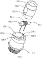
- the holder 100 includes an upper holding unit 105 and a lower holding unit 106 which are engaged with each other.
- the upper holding unit 105 defines a first notch 1052
- the lower holding unit 106 defines a second notch 1061
- each first notch 1052 is opposite to a corresponding one of the second notch 1061.
- the liquid absorbing unit 103 is clamped in the first notch 1052 and the second notch 1061 by the upper holding unit 105 and the lower holding unit 106.
- the upper holding unit 105 defines two of the first notch 1052 that are symmetrical to each other
- the lower holding unit 106 defines two of the second notch 1061 that are symmetrical to each other.
- the lower part of the upper holding unit 105 can insert into the interior of the lower holding unit 106, and the first notch 1052 and the second notch 1061 are oppositely positioned to form two openings, two ends of the liquid absorbing unit 103 extend out of the openings and are exposed in the liquid storage chamber 102.
- Both the upper holding unit 105 and the lower holding unit 106 are made of silica gel material, so the liquid absorbing unit 103 is tightly attached to the upper holding unit 105 and the lower holding unit 106, thereby reducing the probability of the leakage of the e-liquid.
- the outer wall of the lower holding unit 106 is tightly attached to the inner wall of the atomizing sleeve 101, the step 1051 is located on the peripheral wall of the upper holding unit 105, the upper end surface of the lower holding unit 106 is also the bottom of the liquid storage chamber 102, the step 1051 is in a shape of annular, and the narrow annular space between the step 1051 and the inner wall of the atomizing sleeve 101 constitutes the liquid flow channel 107.
- an upward lug 1062 is positioned on the outer side of each second notch 1061 of the lower holding unit 106, the lug 1062 butts against the end face of the liquid absorbing unit 103, the liquid absorbing unit 103 does not completely pass through the second notch 1061, so that only part of the end face of the liquid absorbing unit 103 can touch the e-liquid, thus reducing the suction rate of the e-liquid, and further reducing the probability of leakage of the e-liquid via the second notch 1061.
- a temporary storage cavity 120 is positioned under the holder 100, the holder 100 defines at least one airflow through hole 124 which enables the temporary storage cavity 120 to be configured to communicate with the hollow cavity 1001 of the holder 100, the temporary storage cavity 120 is configured to communicate with the air inlet 115, and the air inlet 115 is positioned in a higher position than the bottom 121 of the temporary storage cavity 120.
- the e-liquid accumulated in the hollow cavity 1001 or flowing back from the vapor transportation pipe 113 can flow through the airflow through hole 124 and is stored in the bottom 121 of the temporary storage cavity 120, and will not flow out of the atomizing device 10 via the air inlet 115, thereby avoiding the contamination of the battery module.
- the external air can flow through the air inlet 115, the temporary storage cavity 120, and the airflow through hole 124 successively, and then enters the hollow cavity 1001.
- the electrode 122 is positioned in the center of the temporary storage cavity 120, a blind hole 123 is positioned in the lower end of the electrode 122, the air inlet 115 is defined in the sidewall of the electrode 122 and is configured to communicate with the blind hole 123, the airflow through hole 124 is disaligned with respect to the underneath of the heating element 104, wherein the blind hole 123, the air inlet 115, and the airflow through hole 124 cooperatively form a non-linear airflow channel, which further increases the difficulty of the leakage of the e-liquid out of the atomizing device 10.
- the electrode 122 is located in the center of the holder 100 and disaligned with respect to the underneath of the heating element 104, the top thereof is an enclosed structure, so the e-liquid dripping from the heating element 104 and the liquid absorbing unit 103 cannot directly flow out of the blind hole 123, and must flow through the non-linear liquid channel, and thus is stored in the temporary storage cavity 120.
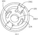
- FIG. 5 illustrates a schematic diagram of the lower holding unit 106.
- the lower holding unit 106 defines a center bore 1064, and the top of the electrode 122 is hermetically assembled in the center bore 1064.
- two symmetrically-distributed airflow through holes 124 are positioned in the lower holding unit 106.
- the airflow through hole 124 is a long strip opening with the section shape of rectangle, oval, or oval-like, the width thereof is between 0.4 and 1.0 mm, and the length thereof is random.
- the surface tension formed on the sidewall of the airflow through hole 124 can basically offset the gravity of the e-liquid, the condensed e-liquid in the hollow cavity 1001 of the holder 100 cannot easily flow into the temporary storage cavity 120 under the airflow through hole 124, and can be evaporated again to generate vapor in the next inhaling.
Landscapes
- Health & Medical Sciences (AREA)
- Engineering & Computer Science (AREA)
- General Health & Medical Sciences (AREA)
- Public Health (AREA)
- Anesthesiology (AREA)
- Biomedical Technology (AREA)
- Heart & Thoracic Surgery (AREA)
- Hematology (AREA)
- Life Sciences & Earth Sciences (AREA)
- Animal Behavior & Ethology (AREA)
- Bioinformatics & Cheminformatics (AREA)
- Pulmonology (AREA)
- Veterinary Medicine (AREA)
- Chemical & Material Sciences (AREA)
- Chemical Kinetics & Catalysis (AREA)
- General Chemical & Material Sciences (AREA)
- Disinfection, Sterilisation Or Deodorisation Of Air (AREA)
- Catching Or Destruction (AREA)
- Electrostatic Spraying Apparatus (AREA)
- Manufacture Of Tobacco Products (AREA)
Abstract
Description
- The present disclosure relates to the field of electronic cigarettes, and particularly, to an atomizing device for an electronic cigarette.
- As substitute goods for cigarettes, electronic cigarettes have aroused more and more attention because of its advantages of safety, convenience, health and environmental friendliness in use. Typically, the electronic cigarettes on the market include an atomizing device and a battery module, and the atomizing device includes an atomizing core and a liquid storage chamber for storing e-liquid. In widely-used schemes, the atomizing core heats and atomizes the e-liquid to generate vapor, thus achieving the feeling of tobacco smoking.
- For example, the atomizing core of the atomizing device of a typical electronic cigarette includes a liquid absorbing unit, a heating element and a holder. The liquid absorbing unit extends out of the holder and absorbs the e-liquid from the liquid storage chamber. In general, the holder is a metal hardware component, and thus the e-liquid in the liquid storage chamber tends to leak from the gap between the holder and the liquid absorbing unit, adversely affecting the user experience. In addition, the inner diameter of the internal vapor transportation pipe is not that big, consequently, the airflow velocity in the vapor transportation pipe is pretty high. As a result, the vapor resulting from the atomization of the e-liquid heated by the heating element tends to condense in the suction nozzle to yield drops, and the drops may be sucked into the mouth along with the vapor, leading to bad user experience.
- In view of the above-described problems, an objective of the disclosure is to provide an atomizing device for an electronic cigarette that can prevent the leakage of e-liquid.
- To achieve the above objective, an embodiment of the present disclosure provides an atomizing device for an electronic cigarette, including:
- an atomizing sleeve defining a liquid storage chamber for containing e-liquid;
- a heating element, which is positioned in the atomizing sleeve, configured to heat and evaporate the e-liquid to generate vapor;
- a liquid absorbing unit, which contacts with the heating element, configured to absorb the e-liquid in the liquid storage chamber and transfer the e-liquid to the heating element; and
- a holder defining a hollow cavity, the holder configured to fix the liquid absorbing unit and the heating element, wherein the heating element is positioned in the hollow cavity;
- wherein,
- a temporary storage cavity is positioned under the holder, the holder defines at least one airflow through hole which is configured to communicate with the temporary storage cavity with the hollow cavity, wherein the temporary storage cavity is configured to communicate with an air inlet, and the air inlet is positioned in a higher position than a bottom of the temporary storage cavity.
- As an improvement of the embodiment, an electrode is positioned in a center of the temporary storage cavity, a blind hole is defined in a lower end of the electrode, the air inlet is defined in a sidewall of the electrode and is configured to communicate with the blind hole, the airflow through hole is disaligned with respect to an underneath of the heating element, wherein the blind hole, the air inlet, and the airflow through hole cooperatively form a non-linear airflow channel.
- As an improvement of the embodiment, the electrode is located in a center of the holder, and a top of the electrode is an enclosed structure.
- As an improvement of the embodiment, the holder defines a center bore, and the top of the electrode is hermetically assembled in the center bore.
- As an improvement of the embodiment, a section of the airflow through hole is in a shape of rectangular or oval, and a width of the airflow through hole is between 0.4 and 1.0 mm.
- As an improvement of the embodiment, the holder includes at least one step protruding from an outer surface thereof into the liquid storage chamber, wherein an outer wall of the step and an inner wall of the atomizing sleeve cooperatively define a ladder-like liquid flow channel therebetween, and at least a part of the liquid absorbing unit extends out of the outer wall of the step to absorb the e-liquid from the liquid flow channel.
- As an improvement of the embodiment, a distance between the outer wall of the step and the inner wall of the atomizing sleeve is between 0.6 and 1.1 mm.
- As an improvement of the embodiment, the holder includes an upper holding unit and a lower holding unit which are engaged with each other, the upper holding unit and the lower holding unit each defines a notch which are opposite to each other, and the liquid absorbing unit is clamped in the notch by the upper holding unit and the lower holding unit.
- As an improvement of the embodiment, an upward lug is positioned on an outer side of each notch of the lower holding unit, the lug butts against an end face of the liquid absorbing unit.
- As an improvement of the embodiment, an outer wall of the lower holding unit is tightly attached to an inner wall of the atomizing sleeve, an upper end surface of the lower holding unit is a bottom of the liquid storage chamber; a step is located on a peripheral wall of the upper holding unit, and a liquid flow channel is defined between the step and the inner wall of the atomizing sleeve.
- As an improvement of the embodiment, the atomizing device includes a suction nozzle positioned in an upper end of the atomizing sleeve, the suction nozzle extends inwards to form a vapor pipe mounting part, an inner diameter of the vapor pipe mounting part is smaller than an inner diameter of the suction nozzle, the vapor pipe mounting part and the suction nozzle are connected via a funnel part, and a vapor transportation pipe is positioned between the vapor pipe mounting part and the holder.
- As an improvement of the embodiment, the suction nozzle includes a nozzle cap, the nozzle cap defines a suction hole, and a diameter of the suction hole is smaller than the inner diameter of the suction nozzle.
- As an improvement of the embodiment, the vapor transportation pipe is a thin-walled metal tube or a thin-walled plastic pipe.
- As an improvement of the embodiment, the liquid absorbing unit is a microporous ceramic rod, wherein a center hole is defined in the liquid absorbing unit, and the heating element is a heating coil wound on the microporous ceramic rod.
- As an improvement of the embodiment, the liquid absorbing unit is made of microcellular foaming material, wherein a center hole is defined in the liquid absorbing unit, and the heating element is a heating coil wound on the microporous ceramic rod.
- Advantages of the atomizing device for an electronic cigarette according to embodiments of the present disclosure are summarized as follows.
- First of all, the temporary storage cavity is configured to communicate with the air inlet, the air inlet is positioned in a higher position than the bottom of the temporary storage cavity, so that the residual e-liquid in the hollow cavity of the holder can flow into and be stored in the temporary storage cavity, and will not leak out of the atomizing device via the air inlet.
- Secondly, the holder for fixing the liquid absorbing unit includes at least one step protruding into the liquid storage chamber, the outer wall of the step and the inner wall of the atomizing sleeve define the ladder-like liquid flow channel, and at least a part of the liquid absorbing unit extends out of the outer wall of the step to absorb the e-liquid from the liquid flow channel; as the ladder-like liquid flow channel is narrow in width, under the molecular tension action of the e-liquid on the inner wall, the liquid suction rate is controllable, thus preventing the leakage of the e-liquid in use. Furthermore, the holder includes the upper holding unit and the lower holding unit, both of which are made of elastic silica gel material and cooperate to tightly clamp the liquid absorbing unit, preventing the leakage of the e-liquid.
- Lastly, a suction nozzle is positioned in the upper end of the atomizing sleeve, the suction nozzle extends inwards to form the vapor pipe mounting part, an inner diameter of the vapor pipe mounting part is smaller than an inner diameter of the suction nozzle, and the vapor pipe mounting part and the suction nozzle are connected via a funnel part. The funnel part can slow down the flow velocity of the vapor, so that the condensed e-liquid is attached thereto and will not enter the mouth of users. Moreover, the atomizing sleeve is not integrated with the vapor transportation pipe, the atomizing sleeve and the vapor transportation pipe are independent from each other, and the vapor transportation pipe is a thin-walled metal tube or a thin-walled plastic pipe, which greatly enlarges the inner space of the vapor transportation channel, providing the space for the backflow of the e-liquid.
- One or more embodiments are illustrated by way of example, and not by limitation, in the figures of the accompanying drawings, wherein elements having the same reference numeral designations represent like elements throughout. The drawings are not to scale, unless otherwise disclosed.
-
FIG. 1 is an axial cutaway view of an atomizing device for an electronic cigarette in accordance with an embodiment of the present disclosure; -
FIG. 2 is a partial enlarged view of part A shown inFIG. 1 ; -
FIG. 3 a schematic view illustrating a cooperation of an upper holding unit and a lower holding unit to clamp a liquid absorbing unit of the atomizing device; -
FIG. 4 is an axial cutaway view of the atomizing device, viewed from another angle; and -
FIG. 5 is a schematic diagram of the lower holding unit. - The structure and use principle of an atomizing device for an electronic cigarette of the present disclosure are further illustrated by embodiments as follows.
- As shown in
FIGS. 1 and2 , an embodiment of the present disclosure provides an atomizingdevice 10 configured to be assembled with a battery assembly to constitute an electronic cigarette. The atomizingdevice 10 includes an atomizingsleeve 101, aheating element 104 and a liquid absorbingunit 103 which are both positioned in the atomizingsleeve 101, and aholder 100 configured to fix theheating element 104 and theliquid absorbing unit 103. The atomizingsleeve 101 defines aliquid storage chamber 102 for containing e-liquid, avapor transportation pipe 113 is positioned in the center of theliquid storage chamber 102, wherein the atomizingsleeve 101, thevapor transportation pipe 113, and theholder 100 cooperatively define theliquid storage chamber 102 therebetween. - The
heating element 104 is positioned in the atomizingsleeve 101 and configured to heat and evaporate the e-liquid to generate vapor. Theliquid absorbing unit 103 contacts with theheating element 104. The liquid absorbingunit 103 is configured to absorb the e-liquid from theliquid storage chamber 102 and transfer the e-liquid to theheating element 104. Theholder 100 defines ahollow cavity 1001, and theheating element 104 is positioned in thehollow cavity 1001. Thehollow cavity 1001 is configured to communicate with thevapor transportation pipe 113 positioned thereon, and theheating element 104 heats the e-liquid to generate vapor which enters thevapor transportation pipe 113 along with the airflow. Anelectrical connection component 114 is positioned on a lower end of the atomizingsleeve 101 to connect to a battery assembly; theelectrical connection component 114 includes anelectrode 122 defining anair inlet 115, and upon inhaling, external air enters thehollow cavity 1001 of theholder 100 via theair inlet 115. - In an exemplary embodiment, the liquid absorbing
unit 103 is a microporous ceramic rod with acenter hole 1031 defined therein, or the liquid absorbingunit 103 is made of microcellular foaming material such as glass fiber material, which can absorb e-liquid from theliquid storage chamber 102 in virtue of capillary action. Thecenter hole 1031 enables the e-liquid to enter the interior of the microporous ceramic rod smoothly, so that the microporous ceramic rod can absorb the e-liquid adequately; theheating element 104 is a heating coil wound on the microporous ceramic rod, and the heating coil heats and evaporates the e-liquid exuding from the surface of the microporous ceramic rod to generate vapor. - The
holder 100 includes at least onestep 1051 protruding towards theliquid storage chamber 102, whereby a ladder-likeliquid flow channel 107 is defined between an outer wall of thestep 1051 and an inner wall of the atomizingsleeve 101. At least a part of theliquid absorbing unit 103 extends out of the outer wall of thestep 1051 to absorb the e-liquid from theliquid flow channel 107. Because thestep 1051 protrudes towards theliquid storage chamber 102, the width between the outer wall of thestep 1051 and the inner wall of the atomizingsleeve 101 is smaller than the width of theliquid storage chamber 102. If the width of theliquid flow channel 107 is appropriately set, the tension action of the outer wall of thestep 1051 and the inner wall of theatomizing sleeve 101 on the e-liquid molecules can slow down the flow velocity of the e-liquid and control the outflow volume of the e-liquid, thus preventing the leakage of the e-liquid from the gap between the liquid absorbingunit 103 and theholder 100 in nonuse of theatomizing device 10. In an exemplary embodiment, to better control the release rate of the e-liquid, the distance between the outer wall of thestep 1051 and the inner wall of theatomizing sleeve 101 is set to be between 0.6 and 1.1 mm, theliquid absorbing unit 103 is positioned at the bottom of theliquid storage chamber 102, so that the e-liquid in theliquid storage chamber 102 slowly permeates into theliquid absorbing unit 103 via theliquid flow channel 107. - In an exemplary embodiment, a
suction nozzle 108 is positioned in an upper end of theatomizing sleeve 101. Thesuction nozzle 108 extends inwards to form a vaporpipe mounting part 110, an inner diameter of the vaporpipe mounting part 110 is smaller than an inner diameter of thesuction nozzle 108, the vaporpipe mounting part 110 and thesuction nozzle 108 are connected via afunnel part 109, and an upper end of thevapor transportation pipe 113 is sleeved on the vaporpipe mounting part 110. Upon inhaling, the vapor flowing upward in thevapor transportation pipe 113 may contain small drops which are condensation products or not completely atomized, when the vapor enters thefunnel part 109 via the vaporpipe mounting part 110, because the inner diameter of thefunnel part 109 gradually increases, the airflow velocity decreases, the small drops tend to attach to the inner wall of thefunnel part 109 or thesuction nozzle 108, then flow back along the inclined plane of thefunnel part 109 and are heated and atomized again. Moreover, thevapor transportation pipe 113 in this illustrated embodiment is not integratedly formed with theatomizing sleeve 101. Thevapor transportation pipe 113 is a thin-walled metal tube or a thin-walled plastic pipe, which, compared with prior arts, greatly increases the inner diameter for airflow passing through, reduces the flow velocity of the vapor, accelerates the condensation of the drops on the pipe wall, and decreases the amount of the drops in the vapor reaching thesuction nozzle 108. - Further, the
suction nozzle 108 includes anozzle cap 111 with asuction hole 112 defined therein, and a diameter of thesuction hole 112 is smaller than the inner diameter of thesuction nozzle 108. In this illustrated embodiment, the diameter of thesuction hole 112 is basically equal to the inner diameter of the vaporpipe mounting part 110. The vapor flow in thevapor transportation pipe 113 is buffered in the relatively large space of thefunnel part 109 and thesuction nozzle 108, then inhaled from thesuction hole 112, and the condensed e-liquid flows back along an inclined plane of thefunnel part 109, thus effectively reducing the probability of inhaling the condensed e-liquid by users. - As shown in
FIG. 3 , theholder 100 includes anupper holding unit 105 and alower holding unit 106 which are engaged with each other. Theupper holding unit 105 defines afirst notch 1052, thelower holding unit 106 defines asecond notch 1061, and eachfirst notch 1052 is opposite to a corresponding one of thesecond notch 1061. Theliquid absorbing unit 103 is clamped in thefirst notch 1052 and thesecond notch 1061 by theupper holding unit 105 and thelower holding unit 106. Specifically, theupper holding unit 105 defines two of thefirst notch 1052 that are symmetrical to each other, and thelower holding unit 106 defines two of thesecond notch 1061 that are symmetrical to each other. The lower part of theupper holding unit 105 can insert into the interior of thelower holding unit 106, and thefirst notch 1052 and thesecond notch 1061 are oppositely positioned to form two openings, two ends of theliquid absorbing unit 103 extend out of the openings and are exposed in theliquid storage chamber 102. Both theupper holding unit 105 and thelower holding unit 106 are made of silica gel material, so the liquid absorbingunit 103 is tightly attached to theupper holding unit 105 and thelower holding unit 106, thereby reducing the probability of the leakage of the e-liquid. - The outer wall of the
lower holding unit 106 is tightly attached to the inner wall of theatomizing sleeve 101, thestep 1051 is located on the peripheral wall of theupper holding unit 105, the upper end surface of thelower holding unit 106 is also the bottom of theliquid storage chamber 102, thestep 1051 is in a shape of annular, and the narrow annular space between thestep 1051 and the inner wall of theatomizing sleeve 101 constitutes theliquid flow channel 107. - In an exemplary embodiment, an
upward lug 1062 is positioned on the outer side of eachsecond notch 1061 of thelower holding unit 106, thelug 1062 butts against the end face of theliquid absorbing unit 103, theliquid absorbing unit 103 does not completely pass through thesecond notch 1061, so that only part of the end face of theliquid absorbing unit 103 can touch the e-liquid, thus reducing the suction rate of the e-liquid, and further reducing the probability of leakage of the e-liquid via thesecond notch 1061. - As shown in
FIG. 4 , atemporary storage cavity 120 is positioned under theholder 100, theholder 100 defines at least one airflow throughhole 124 which enables thetemporary storage cavity 120 to be configured to communicate with thehollow cavity 1001 of theholder 100, thetemporary storage cavity 120 is configured to communicate with theair inlet 115, and theair inlet 115 is positioned in a higher position than the bottom 121 of thetemporary storage cavity 120. The e-liquid accumulated in thehollow cavity 1001 or flowing back from thevapor transportation pipe 113 can flow through the airflow throughhole 124 and is stored in thebottom 121 of thetemporary storage cavity 120, and will not flow out of theatomizing device 10 via theair inlet 115, thereby avoiding the contamination of the battery module. Upon inhaling, the external air can flow through theair inlet 115, thetemporary storage cavity 120, and the airflow throughhole 124 successively, and then enters thehollow cavity 1001. - Specifically, the
electrode 122 is positioned in the center of thetemporary storage cavity 120, ablind hole 123 is positioned in the lower end of theelectrode 122, theair inlet 115 is defined in the sidewall of theelectrode 122 and is configured to communicate with theblind hole 123, the airflow throughhole 124 is disaligned with respect to the underneath of theheating element 104, wherein theblind hole 123, theair inlet 115, and the airflow throughhole 124 cooperatively form a non-linear airflow channel, which further increases the difficulty of the leakage of the e-liquid out of theatomizing device 10. Theelectrode 122 is located in the center of theholder 100 and disaligned with respect to the underneath of theheating element 104, the top thereof is an enclosed structure, so the e-liquid dripping from theheating element 104 and theliquid absorbing unit 103 cannot directly flow out of theblind hole 123, and must flow through the non-linear liquid channel, and thus is stored in thetemporary storage cavity 120. -
FIG. 5 illustrates a schematic diagram of thelower holding unit 106. Thelower holding unit 106 defines acenter bore 1064, and the top of theelectrode 122 is hermetically assembled in the center bore 1064. In this illustrated embodiment, two symmetrically-distributed airflow throughholes 124 are positioned in thelower holding unit 106. Preferably, the airflow throughhole 124 is a long strip opening with the section shape of rectangle, oval, or oval-like, the width thereof is between 0.4 and 1.0 mm, and the length thereof is random. In the width range of the airflow throughhole 124, due to capillary effect, the surface tension formed on the sidewall of the airflow throughhole 124 can basically offset the gravity of the e-liquid, the condensed e-liquid in thehollow cavity 1001 of theholder 100 cannot easily flow into thetemporary storage cavity 120 under the airflow throughhole 124, and can be evaporated again to generate vapor in the next inhaling. - The above embodiments are merely illustrative some exemplary embodiments of the disclosure, but are not intended to limit the scope of the present disclosure. Any equivalent structure or equivalent process variation made based on the specification and drawings of the present disclosure, falls within the scope of the present disclosure.
Claims (15)
- An atomizing device (10) for an electronic cigarette, characterized by comprising:an atomizing sleeve (101) defining a liquid storage chamber (102) for containing e-liquid;a heating element (104), which is positioned in the atomizing sleeve (101), configured to heat and evaporate the e-liquid to generate vapor;a liquid absorbing unit (103), which contacts with the heating element (104), configured to absorb the e-liquid in the liquid storage chamber (102) and transfer the e-liquid to the heating element (104); anda holder (100) defining a hollow cavity (1001), the holder (100) configured to fix the liquid absorbing unit (103) and the heating element (104), wherein the heating element (104) is positioned in the hollow cavity (1001);wherein,a temporary storage cavity (120) is positioned under the holder (100), the holder (100) defines at least one airflow through hole (124) which is configured to communicate with the temporary storage cavity (120) with the hollow cavity (1001), wherein the temporary storage cavity (120) is configured to communicate with an air inlet (115), and the air inlet (115) is positioned in a higher position than a bottom (121) of the temporary storage cavity (120).
- The atomizing device (10) according to claim 1, being characterized in that, an electrode (122) is positioned in a center of the temporary storage cavity (120), a blind hole (123) is defined in a lower end of the electrode (122), the air inlet (115) is defined in a sidewall of the electrode (122) and is configured to communicate with the blind hole (123), the airflow through hole (124) is disaligned with respect to an underneath of the heating element (104), wherein the blind hole (123), the air inlet (115), and the airflow through hole (124) cooperatively form a non-linear airflow channel.
- The atomizing device (10) according to claim 2, being characterized in that, the electrode (122) is located in a center of the holder (100), and a top of the electrode (122) is an enclosed structure.
- The atomizing device (10) according to claim 2, being characterized in that, the holder (100) defines a center bore (1064), and the top of the electrode (122) is hermetically assembled in the center bore (1064).
- The atomizing device (10) according to claim 1, being characterized in that, a section of the airflow through hole (124) is in a shape of rectangular or oval, and a width of the airflow through hole (124) is between 0.4 and 1.0 mm.
- The atomizing device (10) according to claim 1, being characterized in that, the holder (100) comprises at least one step (1051) protruding from an outer surface thereof into the liquid storage chamber (102), wherein an outer wall of the step (1051) and an inner wall of the atomizing sleeve (101) cooperatively define a ladder-like liquid flow channel (107) therebetween, and at least a part of the liquid absorbing unit (103) extends out of the outer wall of the step (1051) to absorb the e-liquid from the liquid flow channel (107).
- The atomizing device (10) according to claim 6, being characterized in that, a distance between the outer wall of the step (1051) and the inner wall of the atomizing sleeve (101) is between 0.6 and 1.1 mm.
- The atomizing device (10) according to claim 1, being characterized in that, the holder (100) comprises an upper holding unit (105) and a lower holding unit (106) which are engaged with each other, the upper holding unit (105) and the lower holding unit (106) each defines a notch (1052, 1061) which are opposite to each other, and the liquid absorbing unit (103) is clamped in the notch (1052, 1061) by the upper holding unit (105) and the lower holding unit (106).
- The atomizing device (10) according to claim 8, being characterized in that, an upward lug (1062) is positioned on an outer side of each notch (1052, 1061) of the lower holding unit (106), the lug (1062) butts against an end face of the liquid absorbing unit (103).
- The atomizing device (10) according to claim 8, being characterized in that, an outer wall of the lower holding unit (106) is tightly attached to an inner wall of the atomizing sleeve (101), an upper end surface of the lower holding unit (106) is a bottom of the liquid storage chamber (102); a step (1051) is located on a peripheral wall of the upper holding unit (105), and a liquid flow channel (107) is defined between the step (1051) and the inner wall of the atomizing sleeve (101).
- The atomizing device (10) according to claim 1, being characterized in that, the atomizing device (10) comprises a suction nozzle (108) positioned in an upper end of the atomizing sleeve (101), the suction nozzle (108) extends inwards to form a vapor pipe mounting part (110), an inner diameter of the vapor pipe mounting part (110) is smaller than an inner diameter of the suction nozzle (108), the vapor pipe mounting part (110) and the suction nozzle (108) are connected via a funnel part (109), and a vapor transportation pipe (113) is positioned between the vapor pipe mounting part (110) and the holder (100).
- The atomizing device (10) according to claim 11, being characterized in that, the suction nozzle (108) comprises a nozzle cap (111), the nozzle cap (111) defines a suction hole (112), and a diameter of the suction hole (112) is smaller than the inner diameter of the suction nozzle (108).
- The atomizing device (10) according to claim 11, being characterized in that, the vapor transportation pipe (113) is a thin-walled metal tube or a thin-walled plastic pipe.
- The atomizing device (10) according to any of claims 1-13, being characterized in that, the liquid absorbing unit (103) is a microporous ceramic rod, wherein a center hole (1031) is defined in the liquid absorbing unit (103), and the heating element (104) is a heating coil wound on the microporous ceramic rod.
- The atomizing device (10) according to any of claims 1-13, being characterized in that, the liquid absorbing unit (103) is made of microcellular foaming material, wherein a center hole (1031) is defined in the liquid absorbing unit (103), and the heating element (104) is a heating coil wound on the microporous ceramic rod.
Applications Claiming Priority (1)
| Application Number | Priority Date | Filing Date | Title |
|---|---|---|---|
| CN201621046106.6U CN206079029U (en) | 2016-09-09 | 2016-09-09 | Electronic cigarette atomizer |
Publications (2)
| Publication Number | Publication Date |
|---|---|
| EP3292775A1 true EP3292775A1 (en) | 2018-03-14 |
| EP3292775B1 EP3292775B1 (en) | 2020-11-04 |
Family
ID=58475073
Family Applications (1)
| Application Number | Title | Priority Date | Filing Date |
|---|---|---|---|
| EP17020404.4A Active EP3292775B1 (en) | 2016-09-09 | 2017-09-06 | Atomizing device for electronic cigarette |
Country Status (5)
| Country | Link |
|---|---|
| US (1) | US10609960B2 (en) |
| EP (1) | EP3292775B1 (en) |
| JP (1) | JP6526129B2 (en) |
| KR (1) | KR101978706B1 (en) |
| CN (1) | CN206079029U (en) |
Cited By (9)
| Publication number | Priority date | Publication date | Assignee | Title |
|---|---|---|---|---|
| EP3563700A1 (en) * | 2018-05-04 | 2019-11-06 | Shenzhen Smoore Technology Limited | Atomizer and electronic cigarette |
| EP3714716A1 (en) * | 2019-03-29 | 2020-09-30 | Nerudia Limited | Aerosol delivery device |
| EP3714708A1 (en) * | 2019-03-29 | 2020-09-30 | Nerudia Limited | Aerosol delivery device |
| US11213638B2 (en) | 2016-03-24 | 2022-01-04 | Nicoventures Trading Limited | Vapor provision system |
| US11241043B2 (en) | 2016-03-24 | 2022-02-08 | Nicoventures Trading Limited | Vapor provision apparatus |
| EP3954232A4 (en) * | 2020-01-19 | 2022-06-29 | Shenzen Zun Yi Pin Technology Co., Ltd. | Atomizer having air pressure surge bin and application thereof |
| EP3871537A4 (en) * | 2018-10-24 | 2022-08-10 | Changzhou Patent Electronic Technology Co., Ltd | CARTRIDGE AND ELECTRONIC CIGARETTE |
| EP4133953A4 (en) * | 2020-04-10 | 2023-09-20 | Shenzhen First Union Technology Co., Ltd. | ATOMIZER AND ELECTRONIC CIGARETTE |
| US12527350B2 (en) | 2019-03-29 | 2026-01-20 | Imperial Tobacco Limited | Aerosol delivery device |
Families Citing this family (36)
| Publication number | Priority date | Publication date | Assignee | Title |
|---|---|---|---|---|
| KR102060860B1 (en) * | 2016-07-16 | 2019-12-30 | 석인선 | Modularized vaporizer |
| US10834967B2 (en) * | 2016-12-27 | 2020-11-17 | Gofire, Inc. | System and method for managing concentrate usage of a user |
| US10314340B2 (en) | 2017-04-21 | 2019-06-11 | Rai Strategic Holdings, Inc. | Refillable aerosol delivery device and related method |
| CN207040890U (en) * | 2017-06-20 | 2018-02-27 | 深圳市合元科技有限公司 | A kind of Electromagnetic Heating electronic cigarette |
| US10603459B2 (en) * | 2017-07-20 | 2020-03-31 | Eric Kotch | Variable viscosity vaporizer cartridge |
| JP7436362B2 (en) * | 2017-10-26 | 2024-02-21 | フィリップ・モーリス・プロダクツ・ソシエテ・アノニム | Cartridge assembly for aerosol generation systems with leak protection |
| WO2019144308A1 (en) * | 2018-01-24 | 2019-08-01 | 深圳麦克韦尔股份有限公司 | Electronic cigarette and atomizer thereof |
| GB2576298B (en) | 2018-06-29 | 2022-06-22 | Nicoventures Trading Ltd | Vapour Provision Device |
| GB201818270D0 (en) | 2018-11-09 | 2018-12-26 | Nicoventures Trading Ltd | Component for a vapour provision system |
| CN209135478U (en) * | 2018-11-28 | 2019-07-23 | 深圳市华诚达精密工业有限公司 | A kind of heating atomization construction and device of two sides feed liquor porous material multi-surface |
| WO2020192264A1 (en) * | 2019-03-26 | 2020-10-01 | 深圳市山杨树科技有限公司 | Electronic cigarette atomizer and electronic cigarette |
| KR102353864B1 (en) | 2019-04-23 | 2022-01-20 | 주식회사 케이티앤지 | Cartridge and aerosol generating device comprising thereof |
| CN110051045A (en) * | 2019-04-24 | 2019-07-26 | 深圳市金致远科技有限公司 | A kind of atomizer and electronic cigarette |
| KR102326001B1 (en) * | 2019-07-24 | 2021-11-12 | 주식회사 케이티앤지 | Cartridge and Aerosol generating device including the same |
| CN110403253A (en) * | 2019-08-26 | 2019-11-05 | 惠州市新泓威科技有限公司 | The electronic smoke atomizer of tobacco juice can be preheated |
| CN111165880B (en) * | 2019-11-22 | 2024-08-30 | 深圳市你我网络科技有限公司 | Atomizer |
| US11484062B2 (en) | 2019-11-26 | 2022-11-01 | Altria Client Services Llc | Nicotine pod assemblies and nicotine e-vaping devices |
| US11564416B2 (en) | 2019-11-26 | 2023-01-31 | Altria Client Services Llc | Non-nicotine pod assemblies and non-nicotine e-vaping devices |
| US11576432B2 (en) | 2019-11-26 | 2023-02-14 | Altria Client Services Llc | Nicotine pod assemblies and nicotine e-vaping devices |
| US11528939B2 (en) | 2019-11-26 | 2022-12-20 | Altria Client Services Llc | Non-nicotine pod assemblies and non-nicotine e-vaping devices |
| US11490656B2 (en) * | 2019-11-26 | 2022-11-08 | Altria Client Services Llc | Nicotine pod assemblies and nicotine e-vaping devices |
| US11528938B2 (en) * | 2019-11-26 | 2022-12-20 | Altria Client Services Llc | Non-nicotine pod assemblies and non-nicotine e-vaping devices |
| CN110897201A (en) * | 2019-12-18 | 2020-03-24 | 深圳尊一品科技有限公司 | Atomizing device with stable aerosol components and application thereof |
| US12279647B2 (en) | 2019-12-23 | 2025-04-22 | Pax Labs, Inc. | Vaporizer cartridge |
| CN111011932B (en) * | 2019-12-26 | 2025-03-21 | 深圳麦克韦尔科技有限公司 | Electronic atomization device and atomizer thereof |
| EP4090187B1 (en) | 2020-01-14 | 2026-01-07 | Juul Labs, Inc. | Hybrid gel-fiber wick for use in a vaporizer device |
| WO2021196113A1 (en) * | 2020-04-02 | 2021-10-07 | 昂纳自动化技术(深圳)有限公司 | Conjoined cigarette |
| EP4082360B1 (en) * | 2020-04-23 | 2026-01-21 | China Tobacco Hunan Industrial Co., Ltd. | Ultrasonic atomizer and electronic cigarette |
| WO2021226834A1 (en) * | 2020-05-12 | 2021-11-18 | 深圳麦克韦尔科技有限公司 | Atomization device |
| CN111657549B (en) * | 2020-05-15 | 2025-03-14 | 深圳麦克韦尔科技有限公司 | Electronic atomization device and atomizer thereof |
| KR102573820B1 (en) * | 2020-12-21 | 2023-08-31 | 주식회사 케이티앤지 | Device for generating aerosol |
| US20220248754A1 (en) * | 2021-02-08 | 2022-08-11 | Shenzhen Eigate Technology Co., Ltd. | Atomizing assembly and electronic cigarette comprising the same |
| KR102542022B1 (en) * | 2021-04-29 | 2023-06-12 | 주식회사 케이티앤지 | Cartridges and device for generating aerosol including the same |
| USD1028336S1 (en) | 2021-06-22 | 2024-05-21 | Pax Labs, Inc. | Vaporizer cartridge |
| CN113876045B (en) * | 2021-11-04 | 2025-12-16 | 深圳市斯科尔科技股份有限公司 | Modular core subassembly, atomizing device and atomizing equipment generate heat |
| CN218245657U (en) * | 2022-09-19 | 2023-01-10 | 深圳麦克韦尔科技有限公司 | Atomizer |
Citations (6)
| Publication number | Priority date | Publication date | Assignee | Title |
|---|---|---|---|---|
| EP2801270A2 (en) * | 2013-05-07 | 2014-11-12 | Shenzhen First Union Technology Co., Ltd. | Atomizing device and electronic cigarette having same |
| CN204317492U (en) * | 2014-11-14 | 2015-05-13 | 深圳市合元科技有限公司 | Be applicable to atomising device and the electronic cigarette of fluid matrix |
| CN104605482A (en) * | 2015-01-05 | 2015-05-13 | 深圳市合元科技有限公司 | Replaceable atomization unit and atomizer and electronic cigarette including the same |
| US20160073692A1 (en) * | 2014-09-17 | 2016-03-17 | Fontem Holdings 2 B.V. | Device for storing and vaporizing liquid media |
| CN205456063U (en) * | 2016-01-29 | 2016-08-17 | 深圳市合元科技有限公司 | Electronic cigarette atomizer and electronic cigarette |
| CN206043435U (en) * | 2016-08-25 | 2017-03-29 | 深圳市合元科技有限公司 | Nebulizer and the electronic cigarette including the nebulizer |
Family Cites Families (7)
| Publication number | Priority date | Publication date | Assignee | Title |
|---|---|---|---|---|
| EP2993997B1 (en) * | 2013-05-10 | 2023-08-02 | Fontem Ventures B.V. | Flavor vortex device |
| KR200477818Y1 (en) | 2013-11-01 | 2015-07-27 | 주식회사 힐쎈 | Portable liquid phase evaporation inhalation device |
| KR101736445B1 (en) * | 2014-09-15 | 2017-05-31 | 주식회사 제이에프티 | Electronic cigarette |
| CN104366695B (en) * | 2014-10-29 | 2017-12-08 | 深圳麦克韦尔股份有限公司 | Atomizer, atomizing component and inhalator |
| CN105559148B (en) * | 2016-02-27 | 2018-08-28 | 卓尔悦欧洲控股有限公司 | Atomizer and its electronic cigarette |
| CN105795527B (en) | 2016-06-03 | 2019-01-29 | 湖南中烟工业有限责任公司 | A kind of electronic smoke atomizer and electronic cigarette |
| EP3476230B1 (en) * | 2016-06-28 | 2020-08-05 | Changzhou Jwei Intelligent Technology Co., Ltd. | Atomizer and electronic cigarette |
-
2016
- 2016-09-09 CN CN201621046106.6U patent/CN206079029U/en active Active
-
2017
- 2017-09-05 US US15/695,031 patent/US10609960B2/en active Active
- 2017-09-06 EP EP17020404.4A patent/EP3292775B1/en active Active
- 2017-09-06 JP JP2017171235A patent/JP6526129B2/en active Active
- 2017-09-07 KR KR1020170114364A patent/KR101978706B1/en active Active
Patent Citations (6)
| Publication number | Priority date | Publication date | Assignee | Title |
|---|---|---|---|---|
| EP2801270A2 (en) * | 2013-05-07 | 2014-11-12 | Shenzhen First Union Technology Co., Ltd. | Atomizing device and electronic cigarette having same |
| US20160073692A1 (en) * | 2014-09-17 | 2016-03-17 | Fontem Holdings 2 B.V. | Device for storing and vaporizing liquid media |
| CN204317492U (en) * | 2014-11-14 | 2015-05-13 | 深圳市合元科技有限公司 | Be applicable to atomising device and the electronic cigarette of fluid matrix |
| CN104605482A (en) * | 2015-01-05 | 2015-05-13 | 深圳市合元科技有限公司 | Replaceable atomization unit and atomizer and electronic cigarette including the same |
| CN205456063U (en) * | 2016-01-29 | 2016-08-17 | 深圳市合元科技有限公司 | Electronic cigarette atomizer and electronic cigarette |
| CN206043435U (en) * | 2016-08-25 | 2017-03-29 | 深圳市合元科技有限公司 | Nebulizer and the electronic cigarette including the nebulizer |
Cited By (14)
| Publication number | Priority date | Publication date | Assignee | Title |
|---|---|---|---|---|
| US11213638B2 (en) | 2016-03-24 | 2022-01-04 | Nicoventures Trading Limited | Vapor provision system |
| US11241043B2 (en) | 2016-03-24 | 2022-02-08 | Nicoventures Trading Limited | Vapor provision apparatus |
| US11564417B2 (en) | 2018-05-04 | 2023-01-31 | Shenzhen Smoore Technology Limited | Heating assembly, atomizer and electronic atomizing device |
| EP3563700A1 (en) * | 2018-05-04 | 2019-11-06 | Shenzhen Smoore Technology Limited | Atomizer and electronic cigarette |
| EP4544939A3 (en) * | 2018-05-04 | 2025-07-23 | Shenzhen Smoore Technology Limited | Atomizer and electronic cigarette |
| EP3871537A4 (en) * | 2018-10-24 | 2022-08-10 | Changzhou Patent Electronic Technology Co., Ltd | CARTRIDGE AND ELECTRONIC CIGARETTE |
| US11992046B2 (en) | 2018-10-24 | 2024-05-28 | Changzhou Patent Electronic Technology Co., LTD | Cartridge and electronic cigarette |
| WO2020200657A1 (en) * | 2019-03-29 | 2020-10-08 | Nerudia Limited | Aerosol delivery device |
| WO2020200648A1 (en) * | 2019-03-29 | 2020-10-08 | Nerudia Limited | Aerosol delivery device |
| EP3714708A1 (en) * | 2019-03-29 | 2020-09-30 | Nerudia Limited | Aerosol delivery device |
| EP3714716A1 (en) * | 2019-03-29 | 2020-09-30 | Nerudia Limited | Aerosol delivery device |
| US12527350B2 (en) | 2019-03-29 | 2026-01-20 | Imperial Tobacco Limited | Aerosol delivery device |
| EP3954232A4 (en) * | 2020-01-19 | 2022-06-29 | Shenzen Zun Yi Pin Technology Co., Ltd. | Atomizer having air pressure surge bin and application thereof |
| EP4133953A4 (en) * | 2020-04-10 | 2023-09-20 | Shenzhen First Union Technology Co., Ltd. | ATOMIZER AND ELECTRONIC CIGARETTE |
Also Published As
| Publication number | Publication date |
|---|---|
| EP3292775B1 (en) | 2020-11-04 |
| CN206079029U (en) | 2017-04-12 |
| JP6526129B2 (en) | 2019-06-05 |
| KR20180028953A (en) | 2018-03-19 |
| JP2018038399A (en) | 2018-03-15 |
| US20180070637A1 (en) | 2018-03-15 |
| KR101978706B1 (en) | 2019-05-15 |
| US10609960B2 (en) | 2020-04-07 |
Similar Documents
| Publication | Publication Date | Title |
|---|---|---|
| EP3292775B1 (en) | Atomizing device for electronic cigarette | |
| CN206043435U (en) | Nebulizer and the electronic cigarette including the nebulizer | |
| EP3516970B1 (en) | Electronic cigarette atomizer with liquid storage transition cavity | |
| US12478098B2 (en) | Aerosol cartridge with air-liquid channel | |
| CN203072896U (en) | Electronic cigarette and atomizer for electronic cigarette | |
| CN211746948U (en) | Atomizer and aerosol generating device thereof | |
| US10603459B2 (en) | Variable viscosity vaporizer cartridge | |
| US11564415B2 (en) | Slide-on attachment for electronic smoking devices | |
| US20190191781A1 (en) | Electronic cigarette atomizer employing ultrasonic atomizing unit | |
| US20170127723A1 (en) | Ceramic atomizing wick and cigarette cartridge | |
| EP2891415A2 (en) | Atomizer and electronic cigarette having same | |
| EP2979556A1 (en) | Atomizer and electronic cigarette having same | |
| EP3000338A1 (en) | Electronic cigarette | |
| CN106998812B (en) | Devices for storing and evaporating liquid media | |
| CN211631799U (en) | Aerosol bomb with gas-liquid channel | |
| CN106418728A (en) | Atomizer and electronic cigarette thereof | |
| US10709172B2 (en) | Electronic cigarette and atomizer thereof | |
| CN203851816U (en) | Atomizer and electronic cigarette with atomizer | |
| CN110574969A (en) | Atomization device | |
| US20200383383A1 (en) | Assembly for preventing leakage in a vaporization device | |
| US11871785B2 (en) | Atomizer having inner and outer glass tubes | |
| US20180042307A1 (en) | Wickless cartomizer | |
| WO2022253352A1 (en) | Electronic cigarette atomization device and electronic cigarette | |
| TW202119945A (en) | Atomizing unit and non-combustion heating type flavor inhaler | |
| CN214156229U (en) | an electronic atomizer |
Legal Events
| Date | Code | Title | Description |
|---|---|---|---|
| PUAI | Public reference made under article 153(3) epc to a published international application that has entered the european phase |
Free format text: ORIGINAL CODE: 0009012 |
|
| STAA | Information on the status of an ep patent application or granted ep patent |
Free format text: STATUS: THE APPLICATION HAS BEEN PUBLISHED |
|
| AK | Designated contracting states |
Kind code of ref document: A1 Designated state(s): AL AT BE BG CH CY CZ DE DK EE ES FI FR GB GR HR HU IE IS IT LI LT LU LV MC MK MT NL NO PL PT RO RS SE SI SK SM TR |
|
| AX | Request for extension of the european patent |
Extension state: BA ME |
|
| STAA | Information on the status of an ep patent application or granted ep patent |
Free format text: STATUS: REQUEST FOR EXAMINATION WAS MADE |
|
| 17P | Request for examination filed |
Effective date: 20180912 |
|
| RBV | Designated contracting states (corrected) |
Designated state(s): AL AT BE BG CH CY CZ DE DK EE ES FI FR GB GR HR HU IE IS IT LI LT LU LV MC MK MT NL NO PL PT RO RS SE SI SK SM TR |
|
| GRAP | Despatch of communication of intention to grant a patent |
Free format text: ORIGINAL CODE: EPIDOSNIGR1 |
|
| STAA | Information on the status of an ep patent application or granted ep patent |
Free format text: STATUS: GRANT OF PATENT IS INTENDED |
|
| INTG | Intention to grant announced |
Effective date: 20200703 |
|
| GRAS | Grant fee paid |
Free format text: ORIGINAL CODE: EPIDOSNIGR3 |
|
| GRAA | (expected) grant |
Free format text: ORIGINAL CODE: 0009210 |
|
| STAA | Information on the status of an ep patent application or granted ep patent |
Free format text: STATUS: THE PATENT HAS BEEN GRANTED |
|
| AK | Designated contracting states |
Kind code of ref document: B1 Designated state(s): AL AT BE BG CH CY CZ DE DK EE ES FI FR GB GR HR HU IE IS IT LI LT LU LV MC MK MT NL NO PL PT RO RS SE SI SK SM TR |
|
| REG | Reference to a national code |
Ref country code: GB Ref legal event code: FG4D |
|
| REG | Reference to a national code |
Ref country code: CH Ref legal event code: EP |
|
| REG | Reference to a national code |
Ref country code: AT Ref legal event code: REF Ref document number: 1329670 Country of ref document: AT Kind code of ref document: T Effective date: 20201115 |
|
| REG | Reference to a national code |
Ref country code: DE Ref legal event code: R096 Ref document number: 602017026607 Country of ref document: DE |
|
| REG | Reference to a national code |
Ref country code: IE Ref legal event code: FG4D |
|
| REG | Reference to a national code |
Ref country code: NL Ref legal event code: MP Effective date: 20201104 |
|
| REG | Reference to a national code |
Ref country code: AT Ref legal event code: MK05 Ref document number: 1329670 Country of ref document: AT Kind code of ref document: T Effective date: 20201104 |
|
| PG25 | Lapsed in a contracting state [announced via postgrant information from national office to epo] |
Ref country code: NO Free format text: LAPSE BECAUSE OF FAILURE TO SUBMIT A TRANSLATION OF THE DESCRIPTION OR TO PAY THE FEE WITHIN THE PRESCRIBED TIME-LIMIT Effective date: 20210204 Ref country code: RS Free format text: LAPSE BECAUSE OF FAILURE TO SUBMIT A TRANSLATION OF THE DESCRIPTION OR TO PAY THE FEE WITHIN THE PRESCRIBED TIME-LIMIT Effective date: 20201104 Ref country code: PT Free format text: LAPSE BECAUSE OF FAILURE TO SUBMIT A TRANSLATION OF THE DESCRIPTION OR TO PAY THE FEE WITHIN THE PRESCRIBED TIME-LIMIT Effective date: 20210304 Ref country code: GR Free format text: LAPSE BECAUSE OF FAILURE TO SUBMIT A TRANSLATION OF THE DESCRIPTION OR TO PAY THE FEE WITHIN THE PRESCRIBED TIME-LIMIT Effective date: 20210205 Ref country code: FI Free format text: LAPSE BECAUSE OF FAILURE TO SUBMIT A TRANSLATION OF THE DESCRIPTION OR TO PAY THE FEE WITHIN THE PRESCRIBED TIME-LIMIT Effective date: 20201104 |
|
| PG25 | Lapsed in a contracting state [announced via postgrant information from national office to epo] |
Ref country code: SE Free format text: LAPSE BECAUSE OF FAILURE TO SUBMIT A TRANSLATION OF THE DESCRIPTION OR TO PAY THE FEE WITHIN THE PRESCRIBED TIME-LIMIT Effective date: 20201104 Ref country code: ES Free format text: LAPSE BECAUSE OF FAILURE TO SUBMIT A TRANSLATION OF THE DESCRIPTION OR TO PAY THE FEE WITHIN THE PRESCRIBED TIME-LIMIT Effective date: 20201104 Ref country code: AT Free format text: LAPSE BECAUSE OF FAILURE TO SUBMIT A TRANSLATION OF THE DESCRIPTION OR TO PAY THE FEE WITHIN THE PRESCRIBED TIME-LIMIT Effective date: 20201104 Ref country code: BG Free format text: LAPSE BECAUSE OF FAILURE TO SUBMIT A TRANSLATION OF THE DESCRIPTION OR TO PAY THE FEE WITHIN THE PRESCRIBED TIME-LIMIT Effective date: 20210204 Ref country code: PL Free format text: LAPSE BECAUSE OF FAILURE TO SUBMIT A TRANSLATION OF THE DESCRIPTION OR TO PAY THE FEE WITHIN THE PRESCRIBED TIME-LIMIT Effective date: 20201104 Ref country code: LV Free format text: LAPSE BECAUSE OF FAILURE TO SUBMIT A TRANSLATION OF THE DESCRIPTION OR TO PAY THE FEE WITHIN THE PRESCRIBED TIME-LIMIT Effective date: 20201104 Ref country code: IS Free format text: LAPSE BECAUSE OF FAILURE TO SUBMIT A TRANSLATION OF THE DESCRIPTION OR TO PAY THE FEE WITHIN THE PRESCRIBED TIME-LIMIT Effective date: 20210304 |
|
| REG | Reference to a national code |
Ref country code: LT Ref legal event code: MG9D |
|
| PG25 | Lapsed in a contracting state [announced via postgrant information from national office to epo] |
Ref country code: HR Free format text: LAPSE BECAUSE OF FAILURE TO SUBMIT A TRANSLATION OF THE DESCRIPTION OR TO PAY THE FEE WITHIN THE PRESCRIBED TIME-LIMIT Effective date: 20201104 |
|
| PG25 | Lapsed in a contracting state [announced via postgrant information from national office to epo] |
Ref country code: RO Free format text: LAPSE BECAUSE OF FAILURE TO SUBMIT A TRANSLATION OF THE DESCRIPTION OR TO PAY THE FEE WITHIN THE PRESCRIBED TIME-LIMIT Effective date: 20201104 Ref country code: SK Free format text: LAPSE BECAUSE OF FAILURE TO SUBMIT A TRANSLATION OF THE DESCRIPTION OR TO PAY THE FEE WITHIN THE PRESCRIBED TIME-LIMIT Effective date: 20201104 Ref country code: CZ Free format text: LAPSE BECAUSE OF FAILURE TO SUBMIT A TRANSLATION OF THE DESCRIPTION OR TO PAY THE FEE WITHIN THE PRESCRIBED TIME-LIMIT Effective date: 20201104 Ref country code: EE Free format text: LAPSE BECAUSE OF FAILURE TO SUBMIT A TRANSLATION OF THE DESCRIPTION OR TO PAY THE FEE WITHIN THE PRESCRIBED TIME-LIMIT Effective date: 20201104 Ref country code: SM Free format text: LAPSE BECAUSE OF FAILURE TO SUBMIT A TRANSLATION OF THE DESCRIPTION OR TO PAY THE FEE WITHIN THE PRESCRIBED TIME-LIMIT Effective date: 20201104 Ref country code: LT Free format text: LAPSE BECAUSE OF FAILURE TO SUBMIT A TRANSLATION OF THE DESCRIPTION OR TO PAY THE FEE WITHIN THE PRESCRIBED TIME-LIMIT Effective date: 20201104 |
|
| REG | Reference to a national code |
Ref country code: DE Ref legal event code: R097 Ref document number: 602017026607 Country of ref document: DE |
|
| PG25 | Lapsed in a contracting state [announced via postgrant information from national office to epo] |
Ref country code: DK Free format text: LAPSE BECAUSE OF FAILURE TO SUBMIT A TRANSLATION OF THE DESCRIPTION OR TO PAY THE FEE WITHIN THE PRESCRIBED TIME-LIMIT Effective date: 20201104 |
|
| PLBE | No opposition filed within time limit |
Free format text: ORIGINAL CODE: 0009261 |
|
| STAA | Information on the status of an ep patent application or granted ep patent |
Free format text: STATUS: NO OPPOSITION FILED WITHIN TIME LIMIT |
|
| 26N | No opposition filed |
Effective date: 20210805 |
|
| PG25 | Lapsed in a contracting state [announced via postgrant information from national office to epo] |
Ref country code: AL Free format text: LAPSE BECAUSE OF FAILURE TO SUBMIT A TRANSLATION OF THE DESCRIPTION OR TO PAY THE FEE WITHIN THE PRESCRIBED TIME-LIMIT Effective date: 20201104 Ref country code: NL Free format text: LAPSE BECAUSE OF FAILURE TO SUBMIT A TRANSLATION OF THE DESCRIPTION OR TO PAY THE FEE WITHIN THE PRESCRIBED TIME-LIMIT Effective date: 20201104 Ref country code: IT Free format text: LAPSE BECAUSE OF FAILURE TO SUBMIT A TRANSLATION OF THE DESCRIPTION OR TO PAY THE FEE WITHIN THE PRESCRIBED TIME-LIMIT Effective date: 20201104 |
|
| PG25 | Lapsed in a contracting state [announced via postgrant information from national office to epo] |
Ref country code: SI Free format text: LAPSE BECAUSE OF FAILURE TO SUBMIT A TRANSLATION OF THE DESCRIPTION OR TO PAY THE FEE WITHIN THE PRESCRIBED TIME-LIMIT Effective date: 20201104 |
|
| REG | Reference to a national code |
Ref country code: CH Ref legal event code: PL |
|
| REG | Reference to a national code |
Ref country code: BE Ref legal event code: MM Effective date: 20210930 |
|
| PG25 | Lapsed in a contracting state [announced via postgrant information from national office to epo] |
Ref country code: IS Free format text: LAPSE BECAUSE OF FAILURE TO SUBMIT A TRANSLATION OF THE DESCRIPTION OR TO PAY THE FEE WITHIN THE PRESCRIBED TIME-LIMIT Effective date: 20210304 Ref country code: MC Free format text: LAPSE BECAUSE OF FAILURE TO SUBMIT A TRANSLATION OF THE DESCRIPTION OR TO PAY THE FEE WITHIN THE PRESCRIBED TIME-LIMIT Effective date: 20201104 |
|
| PG25 | Lapsed in a contracting state [announced via postgrant information from national office to epo] |
Ref country code: LU Free format text: LAPSE BECAUSE OF NON-PAYMENT OF DUE FEES Effective date: 20210906 Ref country code: IE Free format text: LAPSE BECAUSE OF NON-PAYMENT OF DUE FEES Effective date: 20210906 Ref country code: BE Free format text: LAPSE BECAUSE OF NON-PAYMENT OF DUE FEES Effective date: 20210930 |
|
| PG25 | Lapsed in a contracting state [announced via postgrant information from national office to epo] |
Ref country code: LI Free format text: LAPSE BECAUSE OF NON-PAYMENT OF DUE FEES Effective date: 20210930 Ref country code: CH Free format text: LAPSE BECAUSE OF NON-PAYMENT OF DUE FEES Effective date: 20210930 |
|
| PG25 | Lapsed in a contracting state [announced via postgrant information from national office to epo] |
Ref country code: HU Free format text: LAPSE BECAUSE OF FAILURE TO SUBMIT A TRANSLATION OF THE DESCRIPTION OR TO PAY THE FEE WITHIN THE PRESCRIBED TIME-LIMIT; INVALID AB INITIO Effective date: 20170906 |
|
| PG25 | Lapsed in a contracting state [announced via postgrant information from national office to epo] |
Ref country code: CY Free format text: LAPSE BECAUSE OF FAILURE TO SUBMIT A TRANSLATION OF THE DESCRIPTION OR TO PAY THE FEE WITHIN THE PRESCRIBED TIME-LIMIT Effective date: 20201104 |
|
| PG25 | Lapsed in a contracting state [announced via postgrant information from national office to epo] |
Ref country code: MK Free format text: LAPSE BECAUSE OF FAILURE TO SUBMIT A TRANSLATION OF THE DESCRIPTION OR TO PAY THE FEE WITHIN THE PRESCRIBED TIME-LIMIT Effective date: 20201104 |
|
| PG25 | Lapsed in a contracting state [announced via postgrant information from national office to epo] |
Ref country code: MT Free format text: LAPSE BECAUSE OF FAILURE TO SUBMIT A TRANSLATION OF THE DESCRIPTION OR TO PAY THE FEE WITHIN THE PRESCRIBED TIME-LIMIT Effective date: 20201104 |
|
| PGFP | Annual fee paid to national office [announced via postgrant information from national office to epo] |
Ref country code: DE Payment date: 20250916 Year of fee payment: 9 |
|
| PGFP | Annual fee paid to national office [announced via postgrant information from national office to epo] |
Ref country code: GB Payment date: 20250919 Year of fee payment: 9 |
|
| PGFP | Annual fee paid to national office [announced via postgrant information from national office to epo] |
Ref country code: FR Payment date: 20250929 Year of fee payment: 9 |
|
| PG25 | Lapsed in a contracting state [announced via postgrant information from national office to epo] |
Ref country code: TR Free format text: LAPSE BECAUSE OF FAILURE TO SUBMIT A TRANSLATION OF THE DESCRIPTION OR TO PAY THE FEE WITHIN THE PRESCRIBED TIME-LIMIT Effective date: 20201104 |