EP3292309B1 - Method and apparatus for compressor system pressurization - Google Patents
Method and apparatus for compressor system pressurization Download PDFInfo
- Publication number
- EP3292309B1 EP3292309B1 EP16721788.4A EP16721788A EP3292309B1 EP 3292309 B1 EP3292309 B1 EP 3292309B1 EP 16721788 A EP16721788 A EP 16721788A EP 3292309 B1 EP3292309 B1 EP 3292309B1
- Authority
- EP
- European Patent Office
- Prior art keywords
- compressor system
- pressure
- fluid
- bleeding
- downstream
- Prior art date
- Legal status (The legal status is an assumption and is not a legal conclusion. Google has not performed a legal analysis and makes no representation as to the accuracy of the status listed.)
- Active
Links
Images
Classifications
-
- F—MECHANICAL ENGINEERING; LIGHTING; HEATING; WEAPONS; BLASTING
- F04—POSITIVE - DISPLACEMENT MACHINES FOR LIQUIDS; PUMPS FOR LIQUIDS OR ELASTIC FLUIDS
- F04D—NON-POSITIVE-DISPLACEMENT PUMPS
- F04D27/00—Control, e.g. regulation, of pumps, pumping installations or pumping systems specially adapted for elastic fluids
- F04D27/02—Surge control
- F04D27/0207—Surge control by bleeding, bypassing or recycling fluids
-
- F—MECHANICAL ENGINEERING; LIGHTING; HEATING; WEAPONS; BLASTING
- F04—POSITIVE - DISPLACEMENT MACHINES FOR LIQUIDS; PUMPS FOR LIQUIDS OR ELASTIC FLUIDS
- F04D—NON-POSITIVE-DISPLACEMENT PUMPS
- F04D25/00—Pumping installations or systems
- F04D25/16—Combinations of two or more pumps ; Producing two or more separate gas flows
-
- F—MECHANICAL ENGINEERING; LIGHTING; HEATING; WEAPONS; BLASTING
- F02—COMBUSTION ENGINES; HOT-GAS OR COMBUSTION-PRODUCT ENGINE PLANTS
- F02C—GAS-TURBINE PLANTS; AIR INTAKES FOR JET-PROPULSION PLANTS; CONTROLLING FUEL SUPPLY IN AIR-BREATHING JET-PROPULSION PLANTS
- F02C6/00—Plural gas-turbine plants; Combinations of gas-turbine plants with other apparatus; Adaptations of gas-turbine plants for special use
- F02C6/04—Gas-turbine plants providing heated or pressurised working fluid for other apparatus, e.g. without mechanical power output
- F02C6/06—Gas-turbine plants providing heated or pressurised working fluid for other apparatus, e.g. without mechanical power output providing compressed gas
- F02C6/08—Gas-turbine plants providing heated or pressurised working fluid for other apparatus, e.g. without mechanical power output providing compressed gas the gas being bled from the gas-turbine compressor
-
- F—MECHANICAL ENGINEERING; LIGHTING; HEATING; WEAPONS; BLASTING
- F02—COMBUSTION ENGINES; HOT-GAS OR COMBUSTION-PRODUCT ENGINE PLANTS
- F02C—GAS-TURBINE PLANTS; AIR INTAKES FOR JET-PROPULSION PLANTS; CONTROLLING FUEL SUPPLY IN AIR-BREATHING JET-PROPULSION PLANTS
- F02C9/00—Controlling gas-turbine plants; Controlling fuel supply in air- breathing jet-propulsion plants
- F02C9/16—Control of working fluid flow
- F02C9/18—Control of working fluid flow by bleeding, bypassing or acting on variable working fluid interconnections between turbines or compressors or their stages
-
- F—MECHANICAL ENGINEERING; LIGHTING; HEATING; WEAPONS; BLASTING
- F04—POSITIVE - DISPLACEMENT MACHINES FOR LIQUIDS; PUMPS FOR LIQUIDS OR ELASTIC FLUIDS
- F04D—NON-POSITIVE-DISPLACEMENT PUMPS
- F04D27/00—Control, e.g. regulation, of pumps, pumping installations or pumping systems specially adapted for elastic fluids
- F04D27/009—Control, e.g. regulation, of pumps, pumping installations or pumping systems specially adapted for elastic fluids by bleeding, by passing or recycling fluid
-
- F—MECHANICAL ENGINEERING; LIGHTING; HEATING; WEAPONS; BLASTING
- F04—POSITIVE - DISPLACEMENT MACHINES FOR LIQUIDS; PUMPS FOR LIQUIDS OR ELASTIC FLUIDS
- F04D—NON-POSITIVE-DISPLACEMENT PUMPS
- F04D27/00—Control, e.g. regulation, of pumps, pumping installations or pumping systems specially adapted for elastic fluids
- F04D27/02—Surge control
-
- F—MECHANICAL ENGINEERING; LIGHTING; HEATING; WEAPONS; BLASTING
- F04—POSITIVE - DISPLACEMENT MACHINES FOR LIQUIDS; PUMPS FOR LIQUIDS OR ELASTIC FLUIDS
- F04D—NON-POSITIVE-DISPLACEMENT PUMPS
- F04D27/00—Control, e.g. regulation, of pumps, pumping installations or pumping systems specially adapted for elastic fluids
- F04D27/02—Surge control
- F04D27/0207—Surge control by bleeding, bypassing or recycling fluids
- F04D27/0215—Arrangements therefor, e.g. bleed or by-pass valves
-
- F—MECHANICAL ENGINEERING; LIGHTING; HEATING; WEAPONS; BLASTING
- F04—POSITIVE - DISPLACEMENT MACHINES FOR LIQUIDS; PUMPS FOR LIQUIDS OR ELASTIC FLUIDS
- F04D—NON-POSITIVE-DISPLACEMENT PUMPS
- F04D27/00—Control, e.g. regulation, of pumps, pumping installations or pumping systems specially adapted for elastic fluids
- F04D27/02—Surge control
- F04D27/0269—Surge control by changing flow path between different stages or between a plurality of compressors; load distribution between compressors
-
- F—MECHANICAL ENGINEERING; LIGHTING; HEATING; WEAPONS; BLASTING
- F04—POSITIVE - DISPLACEMENT MACHINES FOR LIQUIDS; PUMPS FOR LIQUIDS OR ELASTIC FLUIDS
- F04B—POSITIVE-DISPLACEMENT MACHINES FOR LIQUIDS; PUMPS
- F04B25/00—Multi-stage pumps
-
- F—MECHANICAL ENGINEERING; LIGHTING; HEATING; WEAPONS; BLASTING
- F04—POSITIVE - DISPLACEMENT MACHINES FOR LIQUIDS; PUMPS FOR LIQUIDS OR ELASTIC FLUIDS
- F04B—POSITIVE-DISPLACEMENT MACHINES FOR LIQUIDS; PUMPS
- F04B41/00—Pumping installations or systems specially adapted for elastic fluids
- F04B41/06—Combinations of two or more pumps
-
- F—MECHANICAL ENGINEERING; LIGHTING; HEATING; WEAPONS; BLASTING
- F04—POSITIVE - DISPLACEMENT MACHINES FOR LIQUIDS; PUMPS FOR LIQUIDS OR ELASTIC FLUIDS
- F04D—NON-POSITIVE-DISPLACEMENT PUMPS
- F04D17/00—Radial-flow pumps, e.g. centrifugal pumps; Helico-centrifugal pumps
- F04D17/08—Centrifugal pumps
- F04D17/10—Centrifugal pumps for compressing or evacuating
- F04D17/12—Multi-stage pumps
-
- F—MECHANICAL ENGINEERING; LIGHTING; HEATING; WEAPONS; BLASTING
- F04—POSITIVE - DISPLACEMENT MACHINES FOR LIQUIDS; PUMPS FOR LIQUIDS OR ELASTIC FLUIDS
- F04D—NON-POSITIVE-DISPLACEMENT PUMPS
- F04D19/00—Axial-flow pumps
- F04D19/02—Multi-stage pumps
Definitions
- Embodiments of the subject matter disclosed herein correspond to methods and apparatuses for pressurization of plants comprising at least two compressor systems in series.
- US-A-2003/0113214 discloses a two-stage oil free compressor assembly including a pressure modulation mechanism.
- compressor system means - in general - both a single compressor, for example a single-stage or multistage (preferably centrifugal) compressor, and a plurality of compressors driven by a gas turbine and/or a steam turbine and/or a variable speed electric motor and/or fixed speed motor; typically, further to said compressors (single or multistage) in a compressor system also other components are usually provided, such for example: suction/discharge isolation valves, suction/discharge pressurization valves (preferably in parallel with isolation valves), throttling valve, suction scrubber, centrifugal compressor, after cooler, anti-surge valve, suction/discharge check valves, anti-choke valve, hot gas bypass valve, cold gas bypass valve(in parallel with anti-surge valve), blow down valve, vent valve, relief valve.
- suction/discharge isolation valves suction/discharge pressurization valves (preferably in parallel with isolation valves), throttling valve, suction scrubber, centrifugal compressor, after cooler,
- the upstream compressor system is a multistage compressor (e.g. low-medium pressure or low-medium-high pressure) and the downstream compressor system is a single-stage compressor (e.g. high pressure or very high pressure).
- the two compressor systems are each one operated by a dedicated driver: for example the upstream compressor system is operated by a turbine, while the downstream one is operated by an electric motor or a gas turbine; other operating means can be -in different cases- provided without departing from the present description.
- the two compressor systems are connected by a pipeline where two valves are provided in parallel: an isolation valve and a pressurization valve.
- the second one acts for the pressurization only of the downstream compressor system.
- this operation is accomplished by suitably venting the downstream compressor system, while the upstream one is kept running, operating in a partial or full recycle mode.
- such plants are used for compressing gas mixtures rich in methane and other hydrocarbons up to pressures higher than 250 bar, in order to perform gas injections in gas wells or similar; particularly it can be considered (as a non-limiting example) that a gas has a relatively high molecular weight when it is equal to or higher than a value comprised between 28-44 Kmol/Kg, depending on the gas composition; it must be stressed that this range of molecular weight is not intended as limiting the invention, but only as an indication for a range in which the advantage achieved by the invention are more strongly felt.
- the pressure drop at the pressurization valve is very high: for example if the upstream compressor system is a low/medium pressure multistage one, such pressure drop can reach about 250 bar; this value is exceeded if the upstream compressor system is a low/medium/high pressure multistage one.
- the Joule-Thompson effect depends on the type of gas and on the temperature and pressure of the gas before expansion; the Joule-Thompson effect describes the temperature change of a gas when it is forced through a valve while kept insulated so that no heat is exchanged with the environment.
- the equation can be put in the differential format: The above equations show the higher is the pressure drop, the higher the temperature drop is if the Joule Thomson coefficient is greater than zero.
- the downstream compressor system has a temperature of about -54°C.
- An important idea is to increase the pressure of the fluid in the downstream compressor system by a discrete increase (by steps) in the pressure of the fluid supplied in the downstream compressor system, obtained by at least one bleeding of a fluid from the upstream compressor system having a pressure lower than the delivery pressure of the upstream compressor system fluid itself.
- the enthalpy variation of the gas that results in the Joule-Thompson effect is divided into a plurality of enthalpy variations.
- First embodiments of the subject matter disclosed herein correspond to a method of pressurizing a downstream compressor system according to claim 1.
- Second embodiments of the subject matter disclosed herein correspond to an apparatus for compressor system pressurization according to claim 4.
- a "bleeding region" as specified in claim 4 can be considered any region, area, or portion of the upstream compressor system in which the fluid pressure is at a pressure lower than a pressure of the fluid in the main header of the upstream compressor system; in some particular (but not limiting) cases such a bleeding region is a compressor stage of the upstream compressor system.
- the method is adapted to pressurizing one downstream compressor system 3 operatively connected to an upstream compressor system 2 by using a bleeding line 5 connected at a first end to the downstream compressor system and at a second end at least to one bleeding region (preferably -but not limited to- a compressor stage) or tie-out region of the upstream compressor system 2.
- the upstream compressor system is preferably be kept running both in an operative or "standard” mode or in a full or partial recycle mode.
- the "discharge pressure in recycle mode” (or “in loop mode) is usually less than the "discharge pressure in operating mode" (both being measured in the main header 21 of the upstream compressor system).
- the main header 21 of the upstream compressor system 2 supplies a supplying pipeline 31 of the downstream compressors system, the two compressor systems 2, 3 being intended to compress an operative fluid at increasing pressures.
- the downstream compressor system pressure referenced above is the pressure of the fluid measured in the supplying pipeline 31: while in normal operating condition (both compressor system 2 and 3 running) fluid pressure in the main header 21 and in the supplying pipeline 31 are substantially equal (any difference is a consequence of the pressure drop of the pipes and fittings in the header 21,31), in case that the downstream compressor system 3 is not running and is depressurized at a pressure less than the fluid pressure in the delivery pipe 21 (while the upstream compressor system 2 is running), the fluid pressure measured in the supplying pipeline 31 is less than the fluid pressure in the delivery pipeline 21, thanks to the fact that an isolation valve connecting the two pipelines 21,31 is kept closed.
- the pressurization step of the downstream compressor system 3 happens at least by supplying the supplying pipeline 31 of the downstream compressor system 3 with a fluid having a pressure higher than the fluid pressure of the downstream compressor system 3, the pressurization step providing at least one first bleeding phase, during which it is provided to
- Such a pressure is “substantially” equal in the sense that it would be equal less any valve pressure drop.
- the pressurization step provides a plurality of bleeding phases following the first bleeding phase where each one of the plurality of bleeding phase provides to
- said bleeding is performed at each delivery pipeline 211,212,213,214 of each one of the compressors 201,202,203,204 of said train of compressors: in this way the overall pressure drop is divided in a plurality of steps; in other embodiment said bleeding is performed (alternatively or in combination with the bleeding at each delivery pipeline) before the first compressor 201 of the train, at the intake pipeline of the upstream compressor system.
- FIG. 2 a first embodiment of an apparatus 1 for compressor system pressurization is shown.
- the apparatus 1 comprises an upstream compressor system 2 comprising a main header 21 and a downstream compressor system 3 comprising a supplying pipeline 31 operatively connected to the main header 21 of the upstream compressor system 2.
- Connection between the main header 21 and the supplying pipeline 31 is preferably made by means of at least one isolation valve 90, of the type known per se in the art; such valve 90 is provided between the main header 21 and the supplying pipeline 31.
- the two compressor systems 2, 3 are intended to compress an operative fluid at increasing pressures, for example the upstream compressor system 2 can compress the fluid from environment pressure to low and medium pressure and the downstream compressor system 3 is adapted to compress the fluid to high pressure.
- the apparatus 1 further comprises at least one bleeding line 5 comprising at least one first bleeding pipeline 54 and a bleeding valve 62.
- the bleeding line 5 is operatively connected to a first bleeding region (preferably a compressor stage) of the upstream compressor system 2 and to the downstream compressor system 3, preferably to the supplying pipeline 31 of the downstream compressor system 3.
- the first bleeding pipeline 54 is connected to such first bleeding region (preferably a compressor stage) of the upstream compressor system 2 and the bleeding valve 62 is placed between the pipeline 54 and the supplying pipeline 31 as shown in the example of fig. 2 .
- the bleeding valve 62 is a control or ON/OFF valve.
- the fluid In the first bleeding region of the upstream compressor system 2 the fluid is at a pressure lower than a pressure of the fluid in the main header 21 of the upstream compressor system 2, during normal operating condition (systems 2 and 3 running).
- the bleeding region of the upstream compressor system 2 can be any region (stage) of the system 2 in which the operating fluid is at such pressure; preferably such bleeding region correspond to a compressor stage.
- the apparatus here referenced with number 10, further comprises a plurality of additional bleeding pipelines 51,52,53,54 operatively connected to said bleeding line 5 and to a respective intermediate bleeding region (compressor stage) of the upstream compressor system 2.
- the fluid in each respective bleeding region (compressor stage), the fluid, in the operating condition, is bled at a pressure lower than a pressure of the fluid in the main header 21 of the upstream compressor system 2, and different from the pressure of another bleeding region.
- bleeding regions of the upstream compressor system 2 are provided, but in other embodiments a different number of them can be provided and also a different position of the tie out and tie in of the bleeding lines (for example bleeding line tie in from compression system 2 suction line and tie out from compression system 3 discharge line).
- the upstream compressor system 2 comprises a train of compressors 201,202,203,204 (in this case four compressors) in series with each other.
- Each compressor 201,202,203,204 of said train of compressors comprises a respective delivery pipeline 211,212,213,214: being in series, each delivery pipeline of an upstream compressor is operatively connected to a supplying pipeline of a downstream compressor, so as to compress the fluid in steps.
- bleeding pipelines 51,52,53,54 are -each one- in communication with a respective delivery pipeline 211,212,213,214.
- all the bleeding pipelines 51,52,53,54 are each one in communication with a respective delivery pipeline 211,212,213,214.
- additional valves can be provided, such for example control or ON/OFF valve.
Landscapes
- Engineering & Computer Science (AREA)
- Mechanical Engineering (AREA)
- General Engineering & Computer Science (AREA)
- Life Sciences & Earth Sciences (AREA)
- Sustainable Development (AREA)
- Combustion & Propulsion (AREA)
- Chemical & Material Sciences (AREA)
- Physics & Mathematics (AREA)
- Fluid Mechanics (AREA)
- Structures Of Non-Positive Displacement Pumps (AREA)
- Control Of Positive-Displacement Pumps (AREA)
- Pipeline Systems (AREA)
- Control Of Positive-Displacement Air Blowers (AREA)
Description
- Embodiments of the subject matter disclosed herein correspond to methods and apparatuses for pressurization of plants comprising at least two compressor systems in series.
-
US-A-2003/0113214 discloses a two-stage oil free compressor assembly including a pressure modulation mechanism. - In the field of pressurized plants it is usual to put a first and a second compressor systems in series, for example when high final pressures have to be reached.
- The term "compressor system" means - in general - both a single compressor, for example a single-stage or multistage (preferably centrifugal) compressor, and a plurality of compressors driven by a gas turbine and/or a steam turbine and/or a variable speed electric motor and/or fixed speed motor; typically, further to said compressors (single or multistage) in a compressor system also other components are usually provided, such for example: suction/discharge isolation valves, suction/discharge pressurization valves (preferably in parallel with isolation valves), throttling valve, suction scrubber, centrifugal compressor, after cooler, anti-surge valve, suction/discharge check valves, anti-choke valve, hot gas bypass valve, cold gas bypass valve(in parallel with anti-surge valve), blow down valve, vent valve, relief valve.
- Preferably, in the present description, the upstream compressor system is a multistage compressor (e.g. low-medium pressure or low-medium-high pressure) and the downstream compressor system is a single-stage compressor (e.g. high pressure or very high pressure).
- Typically the two compressor systems are each one operated by a dedicated driver: for example the upstream compressor system is operated by a turbine, while the downstream one is operated by an electric motor or a gas turbine; other operating means can be -in different cases- provided without departing from the present description.
- The two compressor systems are connected by a pipeline where two valves are provided in parallel: an isolation valve and a pressurization valve.
- While the first valve is used when the plant is running, the second one acts for the pressurization only of the downstream compressor system.
- Indeed if a problem occurs in the downstream compressor system when the plant is running, it may be necessary to depressurize it (for example up to values nearly close to the atmospheric pressure) putting it in shutdown.
- In some cases, this operation is accomplished by suitably venting the downstream compressor system, while the upstream one is kept running, operating in a partial or full recycle mode.
- Thus it results in a situation where the upstream compressor system is in operation and it compresses the gas to a "discharge pressure in recycle mode" (or "in loop mode") that is usually less than the "discharge pressure in operating mode", while the downstream compressor system is at a lower pressure for example equal about to the atmospheric pressure.
- When the whole plant has to be restarted it is firstly necessary to pressurize again the downstream compressor system.
- This is usually accomplished by opening said pressurization valve on the pipeline connecting the two compressor systems; however the opening of the pressurization valve leads to a substantially isoenthalpic expansion of the gas with a relevant temperature drop due to the Joule-Thompson effect.
- In case of a gas having a high molecular weight, the Joule-Thompson effect is particularly important and it leads to a considerable temperature drop in the downstream compressor system.
- For example in the "Oil & Gas" field, such plants are used for compressing gas mixtures rich in methane and other hydrocarbons up to pressures higher than 250 bar, in order to perform gas injections in gas wells or similar; particularly it can be considered (as a non-limiting example) that a gas has a relatively high molecular weight when it is equal to or higher than a value comprised between 28-44 Kmol/Kg, depending on the gas composition; it must be stressed that this range of molecular weight is not intended as limiting the invention, but only as an indication for a range in which the advantage achieved by the invention are more strongly felt.
- In these cases, during the pressurization of the downstream compressor system by means of the pressurization valve, the pressure drop at the pressurization valve is very high: for example if the upstream compressor system is a low/medium pressure multistage one, such pressure drop can reach about 250 bar; this value is exceeded if the upstream compressor system is a low/medium/high pressure multistage one.
- Under such hypotheses the Joule-Thompson effect leads to a temperature drop in the gas and therefore in the downstream compressor system, such to bring the latter to very low temperatures; if the minimum temperature drops below the minimum equipment design temperature, risk of mechanical integrity issues may be achieved.
- With particular reference to
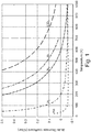
fig. 1 attached, the Joule-Thompson effect depends on the type of gas and on the temperature and pressure of the gas before expansion; the Joule-Thompson effect describes the temperature change of a gas when it is forced through a valve while kept insulated so that no heat is exchanged with the environment. - Experimentally is calculated as:

- T1 is the temperature at the valve outlet, which can be measured downstream of the valve. For example, in the pipe between the valve outlet and the compressor inlet.
- T2 is the temperature at the valve inlet, which can be measured upstream of the valve. For example in the pipe between the valve inlet and the compressor outlet.
- p1 is the pressure at the valve outlet, which can be measured downstream of the valve. For example, in the pipe between the valve outlet and the compressor inlet.
- p2 is the pressure at the valve inlet, which can be measured upstream of the valve. For example in the pipe between the valve inlet and the compressor outlet.
- Δp is the pressure drop across the valve, which can be measured with a dedicated pressure drop devices.
- µJT is the Joule-Thomson coefficient; this value is not measured but calculated.
- which becomes, taking into account that the process is isenthalpic:


- The equation can be put in the differential format:
The above equations show the higher is the pressure drop, the higher the temperature drop is if the Joule Thomson coefficient is greater than zero. - As an example think that with a pressure change of 250 bar (downstream and upstream of the pressurization valve) and with an output gas temperature of about 100°C from the upstream compressor system, with a gas having a molecular weight of about 39 Kmol/kg, the downstream compressor system has a temperature of about -54°C.
- Since the Joule-Thompson effect is directly proportional to the pressure drop, in the prior art, in order to reduce the temperature drop (consequence of the pressure drop when the Joule Thomson coefficient is greater than zero) in the downstream compressor system the delivery pressure of the upstream compressor system is reduced.
- This is accomplished by partially or totally venting the upstream compressor system, reducing the delivery pressure thereof, thus reducing the pressure drop at the pressurization valve and therefore, finally, by mitigating the temperature decrease of the gas and accordingly of the downstream compressor system.
- Although in principle this pressurization method is functional, it has some drawbacks.
- Firstly a loss of production occurs, since after reducing the delivery pressure of the upstream compressor system, it has to be brought again to the working pressure, which is time consuming and it requires some additional energy.
- Secondly, in some cases, it happens that the upstream compressor system has to be completely restarted, with a further time and energy waste and a reduced production.
- Thirdly, environmental impacts, due to the gas emissions, could lead to penalties.
- The present invention is defined in the accompanying claims.
- Therefore there is a general need for an improved method and apparatus for Joule-Thompson effect mitigation for compressor system pressurization.
- An important idea is to increase the pressure of the fluid in the downstream compressor system by a discrete increase (by steps) in the pressure of the fluid supplied in the downstream compressor system, obtained by at least one bleeding of a fluid from the upstream compressor system having a pressure lower than the delivery pressure of the upstream compressor system fluid itself.
- Thus the enthalpy variation of the gas that results in the Joule-Thompson effect is divided into a plurality of enthalpy variations.
- This allows prior art drawbacks to be overcome, since the plant experiences a lower temperature drop: at each pressurization step the pressure and consequently the energy balance change mitigating the difference of temperature at each step.
- Thus prior art drawbacks are overcome since advantageously it is possible to avoid critical low temperature at the outlet of the pressurization valve using high Molecular Weight gas at high pressure.
- Moreover it is possible to improve compressor startup of the downstream compressor system by decreasing the gas density and consequently the absorbed torque, to have a constraint reduction in material selection for compressor systems and equipment, to reduce gas emission due to potential saving of flared and vented gas and to mitigate process loss of production risk.
- First embodiments of the subject matter disclosed herein correspond to a method of pressurizing a downstream compressor system according to
claim 1. - Second embodiments of the subject matter disclosed herein correspond to an apparatus for compressor system pressurization according to
claim 4. - More in general, a "bleeding region" as specified in
claim 4 can be considered any region, area, or portion of the upstream compressor system in which the fluid pressure is at a pressure lower than a pressure of the fluid in the main header of the upstream compressor system; in some particular (but not limiting) cases such a bleeding region is a compressor stage of the upstream compressor system. - The accompanying drawings, which are incorporated herein and constitute a part of the specification, illustrate exemplary embodiments of the present invention and, together with the detailed description, explain these embodiments. In the drawings:
-
Fig.1 shows a diagram of the Joule-Thomson coefficient variation with respect to temperature variation for different gases; -
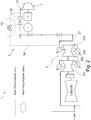
Fig. 2 shows a first embodiment of the subject matter herein described; -
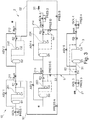
Fig. 3 shows another embodiment of the subject matter herein described. - The following description of exemplary embodiments refers to the accompanying drawings.
- The following description does not limit the invention. Instead, the scope of the invention is defined by the appended claims.
- Reference throughout the specification to "one embodiment" or "an embodiment" means that a particular feature, structure, or characteristic described in connection with an embodiment is included in at least one embodiment of the subject matter disclosed. Thus, the appearance of the phrases "in one embodiment" or "in an embodiment" in various places throughout the specification is not necessarily referring to the same embodiment. Further, the particular features, structures or characteristics may be combined in any suitable manner in one or more embodiments.
- Before describing the
apparatuses figs. 2 and3 , it would be better to describe the method performed, although reference can be made tofig. 2 or3 , for understanding the principle of the method herein described. - In one main embodiment, the method is adapted to pressurizing one
downstream compressor system 3 operatively connected to anupstream compressor system 2 by using a bleedingline 5 connected at a first end to the downstream compressor system and at a second end at least to one bleeding region (preferably -but not limited to- a compressor stage) or tie-out region of theupstream compressor system 2. - This pressurization takes place when the downstream compressor system has, for some reason, being depressurized, while the upstream one is kept running.
- It has to be noted that the upstream compressor system is preferably be kept running both in an operative or "standard" mode or in a full or partial recycle mode.
- In these latter cases all or part the fluid that exits from the main header of the upstream compressor is again recycled in its input.
- In this case (full or partial recycle mode) the "discharge pressure in recycle mode" (or "in loop mode") is usually less than the "discharge pressure in operating mode" (both being measured in the
main header 21 of the upstream compressor system). - The
main header 21 of theupstream compressor system 2 supplies a supplyingpipeline 31 of the downstream compressors system, the twocompressor systems - When the fluid in thee
downstream compressor system 3 is at a pressure lower than a pressure of themain header 21 fluid of theupstream compressor system 2, there is provided a pressurization step of thedownstream compressor system 3 . - It has to be noted that the downstream compressor system pressure referenced above is the pressure of the fluid measured in the supplying pipeline 31: while in normal operating condition (both
compressor system main header 21 and in the supplyingpipeline 31 are substantially equal (any difference is a consequence of the pressure drop of the pipes and fittings in theheader 21,31), in case that thedownstream compressor system 3 is not running and is depressurized at a pressure less than the fluid pressure in the delivery pipe 21 (while theupstream compressor system 2 is running), the fluid pressure measured in the supplyingpipeline 31 is less than the fluid pressure in thedelivery pipeline 21, thanks to the fact that an isolation valve connecting the twopipelines - According to the teaching here given, the pressurization step of the
downstream compressor system 3 happens at least by supplying the supplyingpipeline 31 of thedownstream compressor system 3 with a fluid having a pressure higher than the fluid pressure of thedownstream compressor system 3, the pressurization step providing at least one first bleeding phase, during which it is provided to - (a) bleed from the upstream compressor system 2 a first fluid at a first pressure, lower than the pressure of fluid in the
main header 21 of theupstream compressor system 2 in operating condition and - (b) supply at least said fluid to the supplying
pipeline 31 of thedownstream compressor system 3 until reaching, in thedownstream compressor system 3 fluid a pressure substantially equal to the first pressure. - Such a pressure is "substantially" equal in the sense that it would be equal less any valve pressure drop.
- According to another embodiment, the pressurization step provides a plurality of bleeding phases following the first bleeding phase where each one of the plurality of bleeding phase provides to
- (c) bleed from the upstream compressor system 2 a respective fluid at a respective pressure ranging from a pressure of the fluid in an immediately preceding bleeding phase to the pressure of the fluid in the
delivery pipeline 21 of theupstream compressor system 2 in operating condition - (d) supply at least said fluid to the
downstream compressor system 3, preferably to the supplyingpipeline 31 of thedownstream compressor system 3, till reaching, in the downstream compressor system 3 a fluid pressure substantially equal to the respective pressure of the fluid in the actual bleeding phase (less any occurring bleed valve pressure drop). - In this way a step-by-step pressurization of the
downstream compressor system 3 takes place, reducing the temperature drop in thedownstream system 3 due to the Joule-Thompson effect, as above described. - With reference to
fig. 3 , when theupstream compressor system 2 is provided -at least- by a train of compressors 201,202,203,204 in series with each other, said bleeding is performed preferably at least at a delivery pipeline 211,212,213,214 of each one of the compressors 201,202,203,204 of said train of compressors;. - For even better reduction in the temperature drop control, preferably said bleeding is performed at each delivery pipeline 211,212,213,214 of each one of the compressors 201,202,203,204 of said train of compressors: in this way the overall pressure drop is divided in a plurality of steps; in other embodiment said bleeding is performed (alternatively or in combination with the bleeding at each delivery pipeline) before the
first compressor 201 of the train, at the intake pipeline of the upstream compressor system. - With reference now to
fig. 2 , a first embodiment of anapparatus 1 for compressor system pressurization is shown. - The
apparatus 1 comprises anupstream compressor system 2 comprising amain header 21 and adownstream compressor system 3 comprising a supplyingpipeline 31 operatively connected to themain header 21 of theupstream compressor system 2. - Connection between the
main header 21 and the supplyingpipeline 31 is preferably made by means of at least oneisolation valve 90, of the type known per se in the art;such valve 90 is provided between themain header 21 and the supplyingpipeline 31. - The two
compressor systems upstream compressor system 2 can compress the fluid from environment pressure to low and medium pressure and thedownstream compressor system 3 is adapted to compress the fluid to high pressure. - According to the teaching given here, the
apparatus 1 further comprises at least one bleedingline 5 comprising at least onefirst bleeding pipeline 54 and a bleedingvalve 62. - As can be noticed from
fig. 2 , the bleedingline 5 is operatively connected to a first bleeding region (preferably a compressor stage) of theupstream compressor system 2 and to thedownstream compressor system 3, preferably to the supplyingpipeline 31 of thedownstream compressor system 3. - Preferably, the
first bleeding pipeline 54 is connected to such first bleeding region (preferably a compressor stage) of theupstream compressor system 2 and the bleedingvalve 62 is placed between thepipeline 54 and the supplyingpipeline 31 as shown in the example offig. 2 . - The bleeding
valve 62 is a control or ON/OFF valve. - In the first bleeding region of the
upstream compressor system 2 the fluid is at a pressure lower than a pressure of the fluid in themain header 21 of theupstream compressor system 2, during normal operating condition (systems - In this sense, as in the non-limiting example of
fig. 2 , the bleeding region of theupstream compressor system 2 can be any region (stage) of thesystem 2 in which the operating fluid is at such pressure; preferably such bleeding region correspond to a compressor stage. - In this way a certain fluid flow can be bled from the
upstream system 2 and used for raising the pressure of thedownstream compressor system 3 to normal operating values, reducing the temperature drop due to the Joule-Thomson effect, as described above. - In another example, as shown in
fig. 3 , the apparatus, here referenced withnumber 10, further comprises a plurality ofadditional bleeding pipelines line 5 and to a respective intermediate bleeding region (compressor stage) of theupstream compressor system 2. - Again, in each respective bleeding region (compressor stage), the fluid, in the operating condition, is bled at a pressure lower than a pressure of the fluid in the
main header 21 of theupstream compressor system 2, and different from the pressure of another bleeding region. - In the given example four bleeding regions of the
upstream compressor system 2 are provided, but in other embodiments a different number of them can be provided and also a different position of the tie out and tie in of the bleeding lines (for example bleeding line tie in fromcompression system 2 suction line and tie out fromcompression system 3 discharge line). - Preferably, as in the example of
fig.3 , theupstream compressor system 2 comprises a train of compressors 201,202,203,204 (in this case four compressors) in series with each other. - Each compressor 201,202,203,204 of said train of compressors comprises a respective delivery pipeline 211,212,213,214: being in series, each delivery pipeline of an upstream compressor is operatively connected to a supplying pipeline of a downstream compressor, so as to compress the fluid in steps.
- According to the teaching given herein, at least some of the bleeding
pipelines - Preferably, as shown, all the bleeding
pipelines - In this way it is possible to reduce the overall complexity of the
apparatus 10, while keeping the possibility to bled the fluid from respective bleeding region (compressor stage) in which the fluid is at different pressures, lower than the pressure of the fluid in themain header 21 in normal operation condition of the apparatus, so as to perform the method described above. - Preferably, on each bleeding
pipeline
Claims (7)
- Method of pressurizing a downstream compressor system (3) operatively connected to an upstream compressor system (2) by using a bleeding line (5) connected at a first end to the downstream compressor system (3) and at a second end at least to one bleeding region or tie-out region of the upstream compressor system (2), wherein a main header (21) of the upstream compressor system (2) supplies a supplying pipeline (31) of the downstream compressors system, the two compressor systems (2,3) being intended to compress an operative fluid at increasing pressures, characterized in that when the fluid in the downstream compressor system (3) is at a pressure lower than a pressure of a fluid at the main header (21) of the upstream compressor system (2), there is provided a pressurization step of the downstream compressor system (3) at least by supplying the downstream compressor system (3), preferably the supplying pipeline (31) of the downstream compressor system (3), with a fluid having a pressure higher than the pressure of the downstream compressor system (3), wherein the pressurization step provides at least one first bleeding phase, during which it is provided to:(a) bleed a first fluid from the upstream compressor system (2) at a first pressure, lower than the pressure of fluid in the main header (21) of the upstream compressor system (2) in operating condition; and(b) supply at least said fluid to the supplying pipeline (31) of the downstream compressor system (3) until reaching, in the downstream compressor system (3) a fluid pressure substantially equal to the first pressure less any valve pressure drop.
- Method according to claim 1, wherein the pressurization step provides a plurality of bleeding phases following the first bleeding phase where each one of the plurality of bleeding phase provides to:(c) bleed a respective fluid from the upstream compressor system (2) at a respective pressure ranging from a pressure of fluid of an immediately preceding bleeding phase to the pressure of fluid in the delivery pipeline (21) of the upstream compressor system (2) in operating condition;(d) supply at least said fluid to the downstream compressor system (3), preferably to the supplying pipeline (31) of the downstream compressor system (3), till reaching, in the downstream compressor system (3) a fluid pressure equal to the respective pressure of the fluid in an actual bleeding phase less any bleed valve pressure drop.
- Method according to one of the preceding claims, wherein, the upstream compressor system (2) is provided at least by a train of compressors (201,202,203,204) in series with each other, said bleeding is performed at least at a delivery pipeline (211,212,213,214) of each one of the compressors (201,202,203,204) of said train of compressors, preferably at each delivery pipeline (211,212,213,214) of each one of the compressors (201,202,203,204) of said train of compressors.
- Apparatus (1, 10) for compressor system pressurization comprising:an upstream compressor system (2) comprising a main header (21);a downstream compressor system (3) comprising a supplying pipeline (31) operatively connected to the main header (21) of the upstream compressor system (2);the two compressor systems (2, 3) being intended to compress an operative fluid at increasing pressures;wherein the apparatus (1, 10) comprises at least one bleeding line (5) comprising at least one first bleeding pipeline (54) and a bleeding valve (62), characterized in that the bleeding line (5) is connected to:- a first bleeding region of the upstream compressor system (2), in such first bleeding region the fluid being at a pressure lower than a pressure of the fluid in the main header (21) of the upstream compressor system (2),- the downstream compressor system (3), preferably to a supplying pipeline (31) of the downstream compressor system (3).
- Apparatus (10) according to claim 4, further comprising a plurality of additional bleeding pipelines (51,52,53) operatively connected to said bleeding line (5) and to a respective intermediate bleeding region of the upstream compressor system (2), in which respective bleeding region the fluid, in the operating condition, is at a pressure lower than a pressure of the fluid in the delivery pipeline (21) of the upstream compressor system (2), and different from the pressure of the fluid in another bleeding region.
- Apparatus (10) according to claim 5, wherein the upstream compressor system (2) comprises a train of compressors (201,202,203,204) in series with each other, each compressor (201,202,203,204) of said train of compressors comprising a respective delivery pipeline (211,212,213,214) and wherein at least some of the bleeding pipelines (51,52,53,54) are each one in communication with a respective delivery pipeline (211,212,213,214).
- Apparatus (10) according to claim 5, wherein all the bleeding pipelines (51,52,53,54) are each one in communication with a respective delivery pipeline (211,212,213,214).
Applications Claiming Priority (2)
| Application Number | Priority Date | Filing Date | Title |
|---|---|---|---|
| ITMI20150646 | 2015-05-07 | ||
| PCT/EP2016/060181 WO2016177879A1 (en) | 2015-05-07 | 2016-05-06 | Method and apparatus for compressor system pressurization |
Publications (2)
| Publication Number | Publication Date |
|---|---|
| EP3292309A1 EP3292309A1 (en) | 2018-03-14 |
| EP3292309B1 true EP3292309B1 (en) | 2021-06-30 |
Family
ID=53539798
Family Applications (1)
| Application Number | Title | Priority Date | Filing Date |
|---|---|---|---|
| EP16721788.4A Active EP3292309B1 (en) | 2015-05-07 | 2016-05-06 | Method and apparatus for compressor system pressurization |
Country Status (7)
| Country | Link |
|---|---|
| US (1) | US10724531B2 (en) |
| EP (1) | EP3292309B1 (en) |
| JP (1) | JP6895389B2 (en) |
| KR (1) | KR102549260B1 (en) |
| CN (1) | CN107532605B (en) |
| BR (1) | BR112017023850B1 (en) |
| WO (1) | WO2016177879A1 (en) |
Families Citing this family (1)
| Publication number | Priority date | Publication date | Assignee | Title |
|---|---|---|---|---|
| IT201900013155A1 (en) | 2019-07-29 | 2021-01-29 | Nuovo Pignone Tecnologie Srl | Compression arrangement and method of operation of a compressor |
Family Cites Families (10)
| Publication number | Priority date | Publication date | Assignee | Title |
|---|---|---|---|---|
| JPS5587214A (en) | 1978-12-26 | 1980-07-01 | Fujitsu Ltd | Ipl indication system |
| JPS5746088A (en) * | 1980-09-03 | 1982-03-16 | Hitachi Ltd | Surge preventing device for multi-stage compressor |
| KR19990075384A (en) * | 1998-03-20 | 1999-10-15 | 이헌석 | Compact Turbo Compressor |
| BE1013692A3 (en) * | 2000-09-19 | 2002-06-04 | Atlas Copco Airpower Nv | HIGH PRESSURE, multi-stage centrifugal compressor. |
| US6638029B2 (en) * | 2001-12-19 | 2003-10-28 | Hamilton Sunstrand Corporation | Pressure ratio modulation for a two stage oil free compressor assembly |
| DE10208676A1 (en) * | 2002-02-28 | 2003-09-04 | Man Turbomasch Ag Ghh Borsig | Process for controlling several turbomachines in parallel or in series |
| CN101970291B (en) * | 2008-03-10 | 2016-02-03 | 伯克哈特压缩机股份公司 | Prepare the method and apparatus of gas fuel |
| JP2012504723A (en) * | 2008-07-29 | 2012-02-23 | シエル・インターナシヨネイル・リサーチ・マーチヤツピイ・ベー・ウイ | Compressor control method and apparatus, and hydrocarbon stream cooling method |
| JP5878737B2 (en) * | 2011-11-17 | 2016-03-08 | 株式会社神戸製鋼所 | Compression device |
| CN203035481U (en) * | 2012-12-06 | 2013-07-03 | 上海日立电器有限公司 | Multi-stage compressor for improving low-pressure ratio operation efficiency |
-
2016
- 2016-05-06 US US15/572,204 patent/US10724531B2/en active Active
- 2016-05-06 EP EP16721788.4A patent/EP3292309B1/en active Active
- 2016-05-06 WO PCT/EP2016/060181 patent/WO2016177879A1/en not_active Ceased
- 2016-05-06 JP JP2017556133A patent/JP6895389B2/en active Active
- 2016-05-06 BR BR112017023850-0A patent/BR112017023850B1/en active IP Right Grant
- 2016-05-06 KR KR1020177034227A patent/KR102549260B1/en active Active
- 2016-05-06 CN CN201680026573.9A patent/CN107532605B/en active Active
Non-Patent Citations (1)
| Title |
|---|
| None * |
Also Published As
| Publication number | Publication date |
|---|---|
| BR112017023850B1 (en) | 2022-11-22 |
| BR112017023850A2 (en) | 2018-07-17 |
| JP6895389B2 (en) | 2021-06-30 |
| US10724531B2 (en) | 2020-07-28 |
| JP2018514689A (en) | 2018-06-07 |
| WO2016177879A1 (en) | 2016-11-10 |
| CN107532605A (en) | 2018-01-02 |
| US20180106260A1 (en) | 2018-04-19 |
| CN107532605B (en) | 2019-12-24 |
| EP3292309A1 (en) | 2018-03-14 |
| KR20180006393A (en) | 2018-01-17 |
| KR102549260B1 (en) | 2023-06-28 |
Similar Documents
| Publication | Publication Date | Title |
|---|---|---|
| US7594386B2 (en) | Apparatus for the prevention of critical process variable excursions in one or more turbomachines | |
| CN105392556B (en) | Boosting system and gas boosting method | |
| KR101858648B1 (en) | Method for anti-surge controlling of multi-stage compressing system | |
| US9885284B2 (en) | Turbojet comprising a bleeding system for bleeding air in said turbojet | |
| US20170030268A1 (en) | Method and arrangement for gas turbine engine surge control | |
| JP5990520B2 (en) | Method and system for reducing sealing gas consumption and regulating pressure in high pressure compression systems | |
| JP6537639B2 (en) | Boost system | |
| US20120007368A1 (en) | Pressure reduction plant for a gas or gas mixture | |
| US10190600B2 (en) | Pressure increasing system and method of increasing gas pressure | |
| EP3477116B1 (en) | Method for controlling the outlet pressure of a compressor | |
| EP3056433A1 (en) | Environmental control system utilizing parallel ram heat exchangers | |
| JP6570457B2 (en) | Booster system | |
| EP1418341A2 (en) | Axial thrust balancing system for a centrifugal compressor, having improved safety characteristics | |
| US10724531B2 (en) | Method and apparatus for compressor system pressurization | |
| US11692452B2 (en) | Compressor train start-up using variable inlet guide vanes | |
| US11268524B2 (en) | Method for controlling a plural stage compressor | |
| US20190041130A1 (en) | Method and device for separating air by cryogenic distillation | |
| KR101996276B1 (en) | Gas Line System For Preventing Low Temperature Effect And Method For Preventing Low Temperature Effect Using Gas Line System | |
| US20250327617A1 (en) | Apparatus and method for transferring a fluid from a subcritical gaseous state into a supercritical state | |
| Srinivasan et al. | Application of Integral Geared Compressors in the Process Gas Industry | |
| Toci et al. | Pluto LNG-LNG Optimisation Using Existing Plant Experience |
Legal Events
| Date | Code | Title | Description |
|---|---|---|---|
| STAA | Information on the status of an ep patent application or granted ep patent |
Free format text: STATUS: THE INTERNATIONAL PUBLICATION HAS BEEN MADE |
|
| PUAI | Public reference made under article 153(3) epc to a published international application that has entered the european phase |
Free format text: ORIGINAL CODE: 0009012 |
|
| STAA | Information on the status of an ep patent application or granted ep patent |
Free format text: STATUS: REQUEST FOR EXAMINATION WAS MADE |
|
| 17P | Request for examination filed |
Effective date: 20171211 |
|
| AK | Designated contracting states |
Kind code of ref document: A1 Designated state(s): AL AT BE BG CH CY CZ DE DK EE ES FI FR GB GR HR HU IE IS IT LI LT LU LV MC MK MT NL NO PL PT RO RS SE SI SK SM TR |
|
| AX | Request for extension of the european patent |
Extension state: BA ME |
|
| DAV | Request for validation of the european patent (deleted) | ||
| DAX | Request for extension of the european patent (deleted) | ||
| STAA | Information on the status of an ep patent application or granted ep patent |
Free format text: STATUS: EXAMINATION IS IN PROGRESS |
|
| 17Q | First examination report despatched |
Effective date: 20190410 |
|
| GRAP | Despatch of communication of intention to grant a patent |
Free format text: ORIGINAL CODE: EPIDOSNIGR1 |
|
| STAA | Information on the status of an ep patent application or granted ep patent |
Free format text: STATUS: GRANT OF PATENT IS INTENDED |
|
| INTG | Intention to grant announced |
Effective date: 20201223 |
|
| GRAS | Grant fee paid |
Free format text: ORIGINAL CODE: EPIDOSNIGR3 |
|
| GRAA | (expected) grant |
Free format text: ORIGINAL CODE: 0009210 |
|
| STAA | Information on the status of an ep patent application or granted ep patent |
Free format text: STATUS: THE PATENT HAS BEEN GRANTED |
|
| AK | Designated contracting states |
Kind code of ref document: B1 Designated state(s): AL AT BE BG CH CY CZ DE DK EE ES FI FR GB GR HR HU IE IS IT LI LT LU LV MC MK MT NL NO PL PT RO RS SE SI SK SM TR |
|
| REG | Reference to a national code |
Ref country code: CH Ref legal event code: EP |
|
| REG | Reference to a national code |
Ref country code: AT Ref legal event code: REF Ref document number: 1406597 Country of ref document: AT Kind code of ref document: T Effective date: 20210715 |
|
| REG | Reference to a national code |
Ref country code: DE Ref legal event code: R096 Ref document number: 602016059953 Country of ref document: DE |
|
| REG | Reference to a national code |
Ref country code: IE Ref legal event code: FG4D |
|
| REG | Reference to a national code |
Ref country code: NL Ref legal event code: FP |
|
| REG | Reference to a national code |
Ref country code: LT Ref legal event code: MG9D |
|
| PG25 | Lapsed in a contracting state [announced via postgrant information from national office to epo] |
Ref country code: HR Free format text: LAPSE BECAUSE OF FAILURE TO SUBMIT A TRANSLATION OF THE DESCRIPTION OR TO PAY THE FEE WITHIN THE PRESCRIBED TIME-LIMIT Effective date: 20210630 Ref country code: BG Free format text: LAPSE BECAUSE OF FAILURE TO SUBMIT A TRANSLATION OF THE DESCRIPTION OR TO PAY THE FEE WITHIN THE PRESCRIBED TIME-LIMIT Effective date: 20210930 Ref country code: FI Free format text: LAPSE BECAUSE OF FAILURE TO SUBMIT A TRANSLATION OF THE DESCRIPTION OR TO PAY THE FEE WITHIN THE PRESCRIBED TIME-LIMIT Effective date: 20210630 |
|
| REG | Reference to a national code |
Ref country code: AT Ref legal event code: MK05 Ref document number: 1406597 Country of ref document: AT Kind code of ref document: T Effective date: 20210630 |
|
| PG25 | Lapsed in a contracting state [announced via postgrant information from national office to epo] |
Ref country code: RS Free format text: LAPSE BECAUSE OF FAILURE TO SUBMIT A TRANSLATION OF THE DESCRIPTION OR TO PAY THE FEE WITHIN THE PRESCRIBED TIME-LIMIT Effective date: 20210630 Ref country code: SE Free format text: LAPSE BECAUSE OF FAILURE TO SUBMIT A TRANSLATION OF THE DESCRIPTION OR TO PAY THE FEE WITHIN THE PRESCRIBED TIME-LIMIT Effective date: 20210630 Ref country code: GR Free format text: LAPSE BECAUSE OF FAILURE TO SUBMIT A TRANSLATION OF THE DESCRIPTION OR TO PAY THE FEE WITHIN THE PRESCRIBED TIME-LIMIT Effective date: 20211001 Ref country code: LV Free format text: LAPSE BECAUSE OF FAILURE TO SUBMIT A TRANSLATION OF THE DESCRIPTION OR TO PAY THE FEE WITHIN THE PRESCRIBED TIME-LIMIT Effective date: 20210630 |
|
| REG | Reference to a national code |
Ref country code: NO Ref legal event code: T2 Effective date: 20210630 |
|
| PG25 | Lapsed in a contracting state [announced via postgrant information from national office to epo] |
Ref country code: CZ Free format text: LAPSE BECAUSE OF FAILURE TO SUBMIT A TRANSLATION OF THE DESCRIPTION OR TO PAY THE FEE WITHIN THE PRESCRIBED TIME-LIMIT Effective date: 20210630 Ref country code: EE Free format text: LAPSE BECAUSE OF FAILURE TO SUBMIT A TRANSLATION OF THE DESCRIPTION OR TO PAY THE FEE WITHIN THE PRESCRIBED TIME-LIMIT Effective date: 20210630 Ref country code: SM Free format text: LAPSE BECAUSE OF FAILURE TO SUBMIT A TRANSLATION OF THE DESCRIPTION OR TO PAY THE FEE WITHIN THE PRESCRIBED TIME-LIMIT Effective date: 20210630 Ref country code: SK Free format text: LAPSE BECAUSE OF FAILURE TO SUBMIT A TRANSLATION OF THE DESCRIPTION OR TO PAY THE FEE WITHIN THE PRESCRIBED TIME-LIMIT Effective date: 20210630 Ref country code: ES Free format text: LAPSE BECAUSE OF FAILURE TO SUBMIT A TRANSLATION OF THE DESCRIPTION OR TO PAY THE FEE WITHIN THE PRESCRIBED TIME-LIMIT Effective date: 20210630 Ref country code: PT Free format text: LAPSE BECAUSE OF FAILURE TO SUBMIT A TRANSLATION OF THE DESCRIPTION OR TO PAY THE FEE WITHIN THE PRESCRIBED TIME-LIMIT Effective date: 20211102 Ref country code: RO Free format text: LAPSE BECAUSE OF FAILURE TO SUBMIT A TRANSLATION OF THE DESCRIPTION OR TO PAY THE FEE WITHIN THE PRESCRIBED TIME-LIMIT Effective date: 20210630 Ref country code: AT Free format text: LAPSE BECAUSE OF FAILURE TO SUBMIT A TRANSLATION OF THE DESCRIPTION OR TO PAY THE FEE WITHIN THE PRESCRIBED TIME-LIMIT Effective date: 20210630 |
|
| PG25 | Lapsed in a contracting state [announced via postgrant information from national office to epo] |
Ref country code: PL Free format text: LAPSE BECAUSE OF FAILURE TO SUBMIT A TRANSLATION OF THE DESCRIPTION OR TO PAY THE FEE WITHIN THE PRESCRIBED TIME-LIMIT Effective date: 20210630 |
|
| REG | Reference to a national code |
Ref country code: DE Ref legal event code: R097 Ref document number: 602016059953 Country of ref document: DE |
|
| PG25 | Lapsed in a contracting state [announced via postgrant information from national office to epo] |
Ref country code: DK Free format text: LAPSE BECAUSE OF FAILURE TO SUBMIT A TRANSLATION OF THE DESCRIPTION OR TO PAY THE FEE WITHIN THE PRESCRIBED TIME-LIMIT Effective date: 20210630 |
|
| PLBE | No opposition filed within time limit |
Free format text: ORIGINAL CODE: 0009261 |
|
| STAA | Information on the status of an ep patent application or granted ep patent |
Free format text: STATUS: NO OPPOSITION FILED WITHIN TIME LIMIT |
|
| PG25 | Lapsed in a contracting state [announced via postgrant information from national office to epo] |
Ref country code: AL Free format text: LAPSE BECAUSE OF FAILURE TO SUBMIT A TRANSLATION OF THE DESCRIPTION OR TO PAY THE FEE WITHIN THE PRESCRIBED TIME-LIMIT Effective date: 20210630 |
|
| 26N | No opposition filed |
Effective date: 20220331 |
|
| PG25 | Lapsed in a contracting state [announced via postgrant information from national office to epo] |
Ref country code: IT Free format text: LAPSE BECAUSE OF FAILURE TO SUBMIT A TRANSLATION OF THE DESCRIPTION OR TO PAY THE FEE WITHIN THE PRESCRIBED TIME-LIMIT Effective date: 20210630 |
|
| REG | Reference to a national code |
Ref country code: BE Ref legal event code: MM Effective date: 20220531 |
|
| PG25 | Lapsed in a contracting state [announced via postgrant information from national office to epo] |
Ref country code: MC Free format text: LAPSE BECAUSE OF FAILURE TO SUBMIT A TRANSLATION OF THE DESCRIPTION OR TO PAY THE FEE WITHIN THE PRESCRIBED TIME-LIMIT Effective date: 20210630 Ref country code: LU Free format text: LAPSE BECAUSE OF NON-PAYMENT OF DUE FEES Effective date: 20220506 |
|
| PG25 | Lapsed in a contracting state [announced via postgrant information from national office to epo] |
Ref country code: LT Free format text: LAPSE BECAUSE OF FAILURE TO SUBMIT A TRANSLATION OF THE DESCRIPTION OR TO PAY THE FEE WITHIN THE PRESCRIBED TIME-LIMIT Effective date: 20210630 Ref country code: IE Free format text: LAPSE BECAUSE OF NON-PAYMENT OF DUE FEES Effective date: 20220506 |
|
| PG25 | Lapsed in a contracting state [announced via postgrant information from national office to epo] |
Ref country code: BE Free format text: LAPSE BECAUSE OF NON-PAYMENT OF DUE FEES Effective date: 20220531 |
|
| P01 | Opt-out of the competence of the unified patent court (upc) registered |
Effective date: 20230526 |
|
| PG25 | Lapsed in a contracting state [announced via postgrant information from national office to epo] |
Ref country code: HU Free format text: LAPSE BECAUSE OF FAILURE TO SUBMIT A TRANSLATION OF THE DESCRIPTION OR TO PAY THE FEE WITHIN THE PRESCRIBED TIME-LIMIT; INVALID AB INITIO Effective date: 20160506 |
|
| PG25 | Lapsed in a contracting state [announced via postgrant information from national office to epo] |
Ref country code: MK Free format text: LAPSE BECAUSE OF FAILURE TO SUBMIT A TRANSLATION OF THE DESCRIPTION OR TO PAY THE FEE WITHIN THE PRESCRIBED TIME-LIMIT Effective date: 20210630 Ref country code: CY Free format text: LAPSE BECAUSE OF FAILURE TO SUBMIT A TRANSLATION OF THE DESCRIPTION OR TO PAY THE FEE WITHIN THE PRESCRIBED TIME-LIMIT Effective date: 20210630 |
|
| PG25 | Lapsed in a contracting state [announced via postgrant information from national office to epo] |
Ref country code: MT Free format text: LAPSE BECAUSE OF FAILURE TO SUBMIT A TRANSLATION OF THE DESCRIPTION OR TO PAY THE FEE WITHIN THE PRESCRIBED TIME-LIMIT Effective date: 20210630 |
|
| PGFP | Annual fee paid to national office [announced via postgrant information from national office to epo] |
Ref country code: NL Payment date: 20250423 Year of fee payment: 10 |
|
| PGFP | Annual fee paid to national office [announced via postgrant information from national office to epo] |
Ref country code: DE Payment date: 20250423 Year of fee payment: 10 |
|
| PGFP | Annual fee paid to national office [announced via postgrant information from national office to epo] |
Ref country code: GB Payment date: 20250423 Year of fee payment: 10 |
|
| PGFP | Annual fee paid to national office [announced via postgrant information from national office to epo] |
Ref country code: NO Payment date: 20250424 Year of fee payment: 10 |
|
| PGFP | Annual fee paid to national office [announced via postgrant information from national office to epo] |
Ref country code: FR Payment date: 20250424 Year of fee payment: 10 |
|
| PGFP | Annual fee paid to national office [announced via postgrant information from national office to epo] |
Ref country code: CH Payment date: 20250601 Year of fee payment: 10 |
|
| PG25 | Lapsed in a contracting state [announced via postgrant information from national office to epo] |
Ref country code: TR Free format text: LAPSE BECAUSE OF FAILURE TO SUBMIT A TRANSLATION OF THE DESCRIPTION OR TO PAY THE FEE WITHIN THE PRESCRIBED TIME-LIMIT Effective date: 20210630 |