EP3292281B1 - Valve seat insert - Google Patents
Valve seat insert Download PDFInfo
- Publication number
- EP3292281B1 EP3292281B1 EP15722690.3A EP15722690A EP3292281B1 EP 3292281 B1 EP3292281 B1 EP 3292281B1 EP 15722690 A EP15722690 A EP 15722690A EP 3292281 B1 EP3292281 B1 EP 3292281B1
- Authority
- EP
- European Patent Office
- Prior art keywords
- weight
- valve seat
- seat insert
- vol
- nitrides
- Prior art date
- Legal status (The legal status is an assumption and is not a legal conclusion. Google has not performed a legal analysis and makes no representation as to the accuracy of the status listed.)
- Active
Links
Images




Classifications
-
- F—MECHANICAL ENGINEERING; LIGHTING; HEATING; WEAPONS; BLASTING
- F01—MACHINES OR ENGINES IN GENERAL; ENGINE PLANTS IN GENERAL; STEAM ENGINES
- F01L—CYCLICALLY OPERATING VALVES FOR MACHINES OR ENGINES
- F01L3/00—Lift-valve, i.e. cut-off apparatus with closure members having at least a component of their opening and closing motion perpendicular to the closing faces; Parts or accessories thereof
- F01L3/02—Selecting particular materials for valve-members or valve-seats; Valve-members or valve-seats composed of two or more materials
-
- B—PERFORMING OPERATIONS; TRANSPORTING
- B22—CASTING; POWDER METALLURGY
- B22F—WORKING METALLIC POWDER; MANUFACTURE OF ARTICLES FROM METALLIC POWDER; MAKING METALLIC POWDER; APPARATUS OR DEVICES SPECIALLY ADAPTED FOR METALLIC POWDER
- B22F3/00—Manufacture of workpieces or articles from metallic powder characterised by the manner of compacting or sintering; Apparatus specially adapted therefor ; Presses and furnaces
- B22F3/10—Sintering only
- B22F3/1003—Use of special medium during sintering, e.g. sintering aid
- B22F3/1007—Atmosphere
-
- B—PERFORMING OPERATIONS; TRANSPORTING
- B22—CASTING; POWDER METALLURGY
- B22F—WORKING METALLIC POWDER; MANUFACTURE OF ARTICLES FROM METALLIC POWDER; MAKING METALLIC POWDER; APPARATUS OR DEVICES SPECIALLY ADAPTED FOR METALLIC POWDER
- B22F3/00—Manufacture of workpieces or articles from metallic powder characterised by the manner of compacting or sintering; Apparatus specially adapted therefor ; Presses and furnaces
- B22F3/12—Both compacting and sintering
- B22F3/14—Both compacting and sintering simultaneously
- B22F3/15—Hot isostatic pressing
-
- B—PERFORMING OPERATIONS; TRANSPORTING
- B22—CASTING; POWDER METALLURGY
- B22F—WORKING METALLIC POWDER; MANUFACTURE OF ARTICLES FROM METALLIC POWDER; MAKING METALLIC POWDER; APPARATUS OR DEVICES SPECIALLY ADAPTED FOR METALLIC POWDER
- B22F5/00—Manufacture of workpieces or articles from metallic powder characterised by the special shape of the product
- B22F5/008—Manufacture of workpieces or articles from metallic powder characterised by the special shape of the product of engine cylinder parts or of piston parts other than piston rings
-
- B—PERFORMING OPERATIONS; TRANSPORTING
- B22—CASTING; POWDER METALLURGY
- B22F—WORKING METALLIC POWDER; MANUFACTURE OF ARTICLES FROM METALLIC POWDER; MAKING METALLIC POWDER; APPARATUS OR DEVICES SPECIALLY ADAPTED FOR METALLIC POWDER
- B22F2201/00—Treatment under specific atmosphere
- B22F2201/10—Inert gases
- B22F2201/11—Argon
-
- B—PERFORMING OPERATIONS; TRANSPORTING
- B22—CASTING; POWDER METALLURGY
- B22F—WORKING METALLIC POWDER; MANUFACTURE OF ARTICLES FROM METALLIC POWDER; MAKING METALLIC POWDER; APPARATUS OR DEVICES SPECIALLY ADAPTED FOR METALLIC POWDER
- B22F2201/00—Treatment under specific atmosphere
- B22F2201/20—Use of vacuum
-
- B—PERFORMING OPERATIONS; TRANSPORTING
- B22—CASTING; POWDER METALLURGY
- B22F—WORKING METALLIC POWDER; MANUFACTURE OF ARTICLES FROM METALLIC POWDER; MAKING METALLIC POWDER; APPARATUS OR DEVICES SPECIALLY ADAPTED FOR METALLIC POWDER
- B22F2301/00—Metallic composition of the powder or its coating
- B22F2301/35—Iron
-
- F—MECHANICAL ENGINEERING; LIGHTING; HEATING; WEAPONS; BLASTING
- F02—COMBUSTION ENGINES; HOT-GAS OR COMBUSTION-PRODUCT ENGINE PLANTS
- F02F—CYLINDERS, PISTONS OR CASINGS, FOR COMBUSTION ENGINES; ARRANGEMENTS OF SEALINGS IN COMBUSTION ENGINES
- F02F7/00—Casings, e.g. crankcases
- F02F7/0085—Materials for constructing engines or their parts
Definitions
- the present disclosure relates to a valve seat insert according to the preamble of claim 1. Moreover, the present disclosure relates to a method for manufacturing a valve seat insert.
- An internal combustion engine generally comprises a plurality of valves, each one of which selectively provides a fluid communication between a combustion chamber and another portion of the internal combustion engine, e.g. an intake assembly or an exhaust assembly.
- a valve is generally adapted to abut a valve seat when in a closed position.
- the valve seat may for instance be an integral portion of a cylinder head or a separate component that is connected to the cylinder head. Such a separate component may be referred to as a valve seat insert.
- US 5,934,238 discloses a valve seat insert that comprises a layer consisting essentially of nitride for reducing adhesive and abrasive wear during use. However, there is still a need for improving internal combustion engine valve seat inserts.
- An object of the present disclosure is to provide a valve seat insert that has an appropriate endurance.
- valve seat insert according to claim 1.
- valve seat insert for an internal combustion engine.
- a first portion of the valve seat insert is adapted to contact a cylinder head and a second portion of the valve seat insert is adapted to contact a valve.
- the valve seat insert has a valve seat insert volume, i.e. the entire volume of the material constituting the valve seat insert.
- a major part of the valve seat insert volume i.e. more than 50% thereof, consists of a homogeneous material that comprises nitrides.
- valve seat insert implies a preferred endurance since a large portion of the valve seat insert volume has desired endurance properties by virtue of the presence of nitrides. Moreover, the valve seat according to the above implies that the valve seat insert, and possibly also the cylinder head, may be machined after the valve seat insert has been inserted into the cylinder head.
- the expression “nitrides” relates to a composition of the type MN, where "M” stands for a metallic component and “N” for nitrogen.
- M stands for a metallic component
- N for nitrogen.
- the nitrogen may have a formal oxidation state of -3.
- At least 80 vol%, alternatively at least 90 vol%, preferably least 95 vol%, more preferred at least 98 vol% of the valve seat insert consists of the homogeneous material.
- a homogeneous material amount at or above any one of the above limits implies an improved durability.
- the homogeneous material comprises at least 5 vol%, preferably at least 10 vol%, more preferred at least 15 vol%, of nitrides.
- a nitride amount at or above any one of the above limits implies an appropriately low friction and/or low risk of galling during use.
- the homogeneous material comprises at least 3 vol% of carbides.
- a carbide amount at or above any one of the above limit implies an appropriate wear resistance.
- the homogeneous material comprises carbides within the range of 3 - 6 vol%.
- the homogeneous material comprises nitrides and/or carbonitrides in the range of 12 - 25 vol%, preferably in the range of 14 - 20 vol%.
- an average size of the nitrides is within the range of 1-3 ⁇ m.
- An average nitride size within the above range implies a preferred machinability.
- At least 10 vol%, preferably at least 12 vol%, more preferred at least 15 vol%, of the nitrides consists of vanadium nitrides.
- a vanadium nitride amount at or above any one of the above limit implies an appropriate wear resistance.
- the homogeneous material consists of 0.6-1.6 weight% C, 1.5-3 weight% N, 0.2-0.6 weight% Mn, 0.3-0.7 weight% Si, 4-5 weight% Cr, 2.8-3.6 weight% Mo, 3.4-4 weight% W, 8-10 weight% V, balance Fe.
- the homogeneous material consists of 0.95-1.25 weight% C, 1.5-2.1 weight% N, 0.3-0.5 weight% Mn, 0.4-0.6 weight% Si, 4.2-4.8 weight% Cr, 3-3.4 weight% Mo, 3.5-3.9 weight% W, 8.2-8.8 weight% V, balance Fe.
- a second aspect of the present disclosure relates to an internal combustion engine comprising a valve seat insert according to the first aspect of the present disclosure.
- a third aspect of the present disclosure relates to a vehicle, preferably a heavy-duty vehicle i.e. a vehicle having a gross vehicle weight rating (GVWR) of 11 000 kg or more, comprising an internal combustion engine according to the second aspect of the present disclosure.
- a heavy-duty vehicle i.e. a vehicle having a gross vehicle weight rating (GVWR) of 11 000 kg or more
- GVWR gross vehicle weight rating
- a fourth aspect of the present disclosure relates to a method for manufacturing a valve seat insert for an internal combustion engine.
- the method comprises:
- the nitrided steel powder has a nitrogen content of at least 0.5 weight%, preferably at least 1.0 weight%, more preferred at least 1.5 weight%.
- the nitrided steel powder consists of 0.6-1.6 weight% C, 1.5-3 weight% N, 0.2-0.6 weight% Mn, 0.3-0.7 weight% Si, 4-5 weight% Cr, 2.8-3.6 weight% Mo, 3.4-4 weight% W, 8-10 weight% V, balance Fe.
- the nitrided steel powder consists of 0.95-1.25 weight% C, 1.5-2.1 weight% N, 0.3-0.5 weight% Mn, 0.4-0.6 weight% Si, 4.2-4.8 weight% Cr, 3-3.4 weight% Mo, 3.5-3.9 weight% W, 8.2-8.8 weight% V, balance Fe.
- the nitrided steel powder is densified by high velocity compaction, preferably at room temperature, to form a high velocity compacted part.
- the high velocity compacted part is sintered at a temperature exceeding 1100°C, preferably exceeding 1200°C.
- the nitrided steel powder is densified by hot isostatic pressing.
- the hot isostatic pressing is performed at a temperature exceeding 1100°C, preferably exceeding 1200°C.
- the hot isostatic pressing is performed at a pressure in the range of 100 to 350 MPa.
- the invention will below be described for a vehicle in the form of a truck 1 such as the one illustrated in Fig. 1 .
- the truck 1 should be seen as an example of a vehicle which could comprise a valve seat insert and/or an internal combustion engine according to the present invention.
- the valve seat insert and/or an internal combustion engine of the present invention may be implemented in a plurality of different types of objects, e.g. other types of vehicles.
- the valve seat insert and/or an internal combustion engine could be implemented in a truck, a tractor, a car, a bus, a work machine such as a wheel loader or an articulated hauler or any other type of construction equipment.
- the truck 1 comprises an internal combustion engine 10.
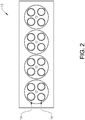
- Fig. 2 is a bottom view of a cylinder head 12 of an internal combustion engine, such as the internal combustion engine 10 illustrated in Fig. 1 .
- a plurality of valve seat inserts 14 are attached to the cylinder head 12.
- each one of the valve seat inserts 14 may be press-fitted into a corresponding opening of the cylinder head 12.
- a valve seat insert 14 instead of, or in addition to, being press-fitted is connected to the cylinder head 12 in another way, such as shrink-fitting, welding, gluing or the like.
- Fig. 3 illustrates an embodiment of a valve seat insert 14.
- the Fig. 3 valve seat insert 14 is suitable for an internal combustion engine, such as the internal combustion engine 10 of the type illustrated in Fig. 1 .
- the Fig. 3 valve seat insert 14 may be suitable for being inserted into a cylinder head, such as the cylinder head 12 illustrated in Fig. 2 .
- Fig. 3 further illustrates that a first portion 16 of the valve seat insert 18 is adapted to contact a cylinder head 12 and a second portion 18 of the valve seat insert 14 is adapted to contact a valve 20.
- the valve seat insert has a valve seat insert volume V.
- valve seat insert volume V consists of a homogeneous material that comprises nitrides.
- valve seat insert 14 consists of the homogeneous material.
- the valve seat insert 14 may be an integral component that consists substantially completely, i.e. save for impurities or the like, of the homogeneous material.
- the valve seat insert 14 may be a separate component that is constituted by one or more parts.
- the homogeneous material may comprise at least 5 vol%, preferably at least 10 vol%, more preferred at least 15 vol%, of nitrides.
- the homogeneous material may comprise at least 3 vol% of carbides, alternatively carbides within the range of 3 - 6 vol%.
- the amount of nitrides and/or carbonitrides M(N,C) may be in the range of 12-25 vol % for the proposed alloy, with a preferred value being approximately 15 vol %.
- the amount of carbides M(C) may be 3-6 vol %, with a preferred value being 5 vol % for the proposed alloy.
- M stands for metallic component of the carbides, carbonitride or nitride, and may be constituted by several of the metallic elements of the alloy.
- the homogeneous material may comprise nitrides and/or carbonitrides in the range of 12 - 25 vol%, preferably in the range of 14 - 20 vol%.
- an average size of the nitrides is within the range of 1-3 ⁇ m.
- An average nitride size within the above range implies a preferred machinability.
- the size of the nitrides can be measured from an image of a cross-section of the homogeneous material, which image has a magnification of for instance 3000-5000 times, taken with e.g. a scanning electron microscope equipped with a back-scatter detector.
- the nitride size may be determined by determining the diameter of the smallest circle that envelopes the nitride.
- the volume fraction of nitrides/carbonitrides/carbides can be calculated based on the image.
- At least 10 vol%, preferably at least 12 vol%, more preferred at least 15 vol%, of the nitrides consists of vanadium nitrides.
- a vanadium nitride amount at or above any one of the above limit implies an appropriate wear resistance.
- the homogeneous material may consist of 0.6-1.6 weight% C, 1.5-3 weight% N, 0.2-0.6 weight% Mn, 0.3-0.7 weight% Si, 4-5 weight% Cr, 2.8-3.6 weight% Mo, 3.4-4 weight% W, 8-10 weight% V, balance Fe.
- the homogeneous material may consists of 0.95-1.25 weight% C, 1.5-2.1 weight% N, 0.3-0.5 weight% Mn, 0.4-0.6 weight% Si, 4.2-4.8 weight% Cr, 3-3.4 weight% Mo, 3.5-3.9 weight% W, 8.2-8.8 weight% V, balance Fe.
- the homogeneous material may consists of 1.1 weight% C, 1.8 weight% N, 0.4 weight% Mn, 0.5 weight% Si, 4.5 weight% Cr, 3.2 weight% Mo, 3.7 weight% W, 8.5 weight% V, balance Fe and unavoidable impurities.
- Fig. 4 and Fig. 5 illustrate embodiments of a method for manufacturing a valve seat insert for an internal combustion engine.
- the inventive method comprises:
- the nitrided steel powder may have a nitrogen content of at least 0.5 weight%, preferably at least 1.0 weight%, more preferred at least 1.5 weight%.
- the nitrided steel powder may consist of 0.6-1.6 weight% C, 1.5-3 weight% N, 0.2-0.6 weight% Mn, 0.3-0.7 weight% Si, 4-5 weight% Cr, 2.8-3.6 weight% Mo, 3.4-4 weight% W, 8-10 weight% V, balance Fe.
- the nitrided steel powder may consist of 0.95-1.25 weight% C, 1.5-2.1 weight% N, 0.3-0.5 weight% Mn, 0.4-0.6 weight% Si, 4.2-4.8 weight% Cr, 3-3.4 weight% Mo, 3.5-3.9 weight% W, 8.2-8.8 weight% V, balance Fe.
- the nitrided steel powder may consists of 1.1 weight% C, 1.8 weight% N, 0.4 weight% Mn, 0.5 weight% Si, 4.5 weight% Cr, 3.2 weight% Mo, 3.7 weight% W, 8.5 weight% V, balance Fe and unavoidable impurities.
- Fig. 4 illustrates an embodiment of the valve seat insert manufacturing method in which the nitrided steel powder is densified by high velocity compaction.
- a first step S10 in the Fig. 4 method the nitrided steel powder arranged in a mould 22.
- the powder in the mould 22 is then compacted at high velocity to thereby form a high velocity compacted part.
- the powder may be compacted at an impact speed of at least 5 m/s.
- embodiments of the valve seat insert manufacturing method may employ even higher speeds. Purely by way of example, in embodiments of the method, the speed may exceed 50 m/s or even 80 m/s.
- the high velocity compacted part is sintered in controlled atmosphere.
- the high velocity compacted part may be sintered at a temperature exceeding 1100°C, preferably at a temperature exceeding 1200 °C, for instance in a sintering oven 23 in a vacuum or in a reducing or inert atmosphere.
- the valve seat insert 14 is obtained. A high velocity compaction performed at or above any one of the above limits could contribute to an appropriate temperature stability during use.
- the nitrided steel powder may be densified by hot isostatic pressing.
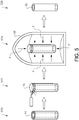
- Fig. 5 illustrates an embodiment of a hot isostatic pressing method.
- step S20 nitrided steel powder is placed inside a mould 24, e.g. a tubular mould.
- the mould 24 is sealed, for instance by connecting a lid 26 to the mould 24 by means of welding.
- step S24 the thus sealed mould 24 is subjected to hot isostatic pressing, i.e. the sealed mould 24 is subjected to an elevated temperature as well as an elevated pressure in a vessel 28.
- the high pressure may be obtained by feeding an inert gas, such as argon into the vessel 28. Moreover, at least the interior of the vessel 28 is heated. As non-limiting examples, the pressure in the vessel may be in the range of 100 to 350 MPa. Moreover, again as a non-limiting example, the temperature in the vessel may exceed 1100°C and may preferably exceed 1200°C. Purely by way of example, the temperature may be in the range of 1000 - 1500 °C, alternatively in the range of 1200 - 1300 °C.
- step S26 the mould 24 and the lid 26 are removed such that a blank 30 for valve seat insert is obtained.
- a blank 30 can thereafter be cut in order to obtain individual valve seat inserts (not shown in Fig. 5 ).
- Fig. 6 illustrates a method for producing a nitrided steel powder.
- the nitrided steel powder produced in the Fig. 6 method may be used in either one of the methods for manufacturing a valve seat insert which have been described hereinabove with reference to Fig. 4 and Fig. 5 , respectively.
- step S30 in Fig. 6 liquid steel 32 is poured into a container 34. Adjacent to the liquid steel 32, nitrogen 36 is discharged, preferably at a high pressure. In the container 34, steel droplets are formed that fall to the bottom of the container 34 as metal powder 36.
- the metal powder 36 obtained in step 30 is thereafter nitrided.
- the metal powder 36 may be nitrided in a bed reactor 38 at a temperature within the range of 550 - 600 °C.
- nitrogen and ammonia may be fed to the bed reactor 38.
Landscapes
- Engineering & Computer Science (AREA)
- Mechanical Engineering (AREA)
- Manufacturing & Machinery (AREA)
- General Engineering & Computer Science (AREA)
- Powder Metallurgy (AREA)
Description
- The present disclosure relates to a valve seat insert according to the preamble of claim 1. Moreover, the present disclosure relates to a method for manufacturing a valve seat insert.
- An internal combustion engine generally comprises a plurality of valves, each one of which selectively provides a fluid communication between a combustion chamber and another portion of the internal combustion engine, e.g. an intake assembly or an exhaust assembly.
- A valve is generally adapted to abut a valve seat when in a closed position. The valve seat may for instance be an integral portion of a cylinder head or a separate component that is connected to the cylinder head. Such a separate component may be referred to as a valve seat insert.
-
US 5,934,238 discloses a valve seat insert that comprises a layer consisting essentially of nitride for reducing adhesive and abrasive wear during use. However, there is still a need for improving internal combustion engine valve seat inserts. - Document
US2011/162612 A1 discloses a valve seat insert according to the preamble of claim 1. - An object of the present disclosure is to provide a valve seat insert that has an appropriate endurance.
- The object is achieved by a valve seat insert according to claim 1.
- As such, the present disclosure relates to a valve seat insert for an internal combustion engine. A first portion of the valve seat insert is adapted to contact a cylinder head and a second portion of the valve seat insert is adapted to contact a valve. The valve seat insert has a valve seat insert volume, i.e. the entire volume of the material constituting the valve seat insert.
- According to the present disclosure, a major part of the valve seat insert volume, i.e. more than 50% thereof, consists of a homogeneous material that comprises nitrides.
- The valve seat insert according to the above implies a preferred endurance since a large portion of the valve seat insert volume has desired endurance properties by virtue of the presence of nitrides. Moreover, the valve seat according to the above implies that the valve seat insert, and possibly also the cylinder head, may be machined after the valve seat insert has been inserted into the cylinder head.
- As used herein, the expression "nitrides" relates to a composition of the type MN, where "M" stands for a metallic component and "N" for nitrogen. For instance, the nitrogen may have a formal oxidation state of -3.
- Optionally, at least 80 vol%, alternatively at least 90 vol%, preferably least 95 vol%, more preferred at least 98 vol% of the valve seat insert consists of the homogeneous material. A homogeneous material amount at or above any one of the above limits implies an improved durability.
- Optionally, the homogeneous material comprises at least 5 vol%, preferably at least 10 vol%, more preferred at least 15 vol%, of nitrides. A nitride amount at or above any one of the above limits implies an appropriately low friction and/or low risk of galling during use.
- Optionally, the homogeneous material comprises at least 3 vol% of carbides. A carbide amount at or above any one of the above limit implies an appropriate wear resistance.
- Optionally, the homogeneous material comprises carbides within the range of 3 - 6 vol%.
- Optionally, the homogeneous material comprises nitrides and/or carbonitrides in the range of 12 - 25 vol%, preferably in the range of 14 - 20 vol%.
- Optionally, an average size of the nitrides is within the range of 1-3 µm. An average nitride size within the above range implies a preferred machinability.
- Optionally, at least 10 vol%, preferably at least 12 vol%, more preferred at least 15 vol%, of the nitrides consists of vanadium nitrides. A vanadium nitride amount at or above any one of the above limit implies an appropriate wear resistance.
- Optionally, the homogeneous material consists of 0.6-1.6 weight% C, 1.5-3 weight% N, 0.2-0.6 weight% Mn, 0.3-0.7 weight% Si, 4-5 weight% Cr, 2.8-3.6 weight% Mo, 3.4-4 weight% W, 8-10 weight% V, balance Fe.
- Optionally, the homogeneous material consists of 0.95-1.25 weight% C, 1.5-2.1 weight% N, 0.3-0.5 weight% Mn, 0.4-0.6 weight% Si, 4.2-4.8 weight% Cr, 3-3.4 weight% Mo, 3.5-3.9 weight% W, 8.2-8.8 weight% V, balance Fe.
- A second aspect of the present disclosure relates to an internal combustion engine comprising a valve seat insert according to the first aspect of the present disclosure.
- A third aspect of the present disclosure relates to a vehicle, preferably a heavy-duty vehicle i.e. a vehicle having a gross vehicle weight rating (GVWR) of 11 000 kg or more, comprising an internal combustion engine according to the second aspect of the present disclosure.
- A fourth aspect of the present disclosure relates to a method for manufacturing a valve seat insert for an internal combustion engine. The method comprises:
- arranging nitrided steel powder in a mould, and
- densifying the nitrided steel powder.
- Optionally, the nitrided steel powder has a nitrogen content of at least 0.5 weight%, preferably at least 1.0 weight%, more preferred at least 1.5 weight%.
- Optionally, the nitrided steel powder consists of 0.6-1.6 weight% C, 1.5-3 weight% N, 0.2-0.6 weight% Mn, 0.3-0.7 weight% Si, 4-5 weight% Cr, 2.8-3.6 weight% Mo, 3.4-4 weight% W, 8-10 weight% V, balance Fe.
- Optionally, the nitrided steel powder consists of 0.95-1.25 weight% C, 1.5-2.1 weight% N, 0.3-0.5 weight% Mn, 0.4-0.6 weight% Si, 4.2-4.8 weight% Cr, 3-3.4 weight% Mo, 3.5-3.9 weight% W, 8.2-8.8 weight% V, balance Fe.
- Optionally, the nitrided steel powder is densified by high velocity compaction, preferably at room temperature, to form a high velocity compacted part.
- Optionally, the high velocity compacted part is sintered at a temperature exceeding 1100°C, preferably exceeding 1200°C.
- Optionally, the nitrided steel powder is densified by hot isostatic pressing.
- Optionally, the hot isostatic pressing is performed at a temperature exceeding 1100°C, preferably exceeding 1200°C.
- Optionally, the hot isostatic pressing is performed at a pressure in the range of 100 to 350 MPa.
- With reference to the appended drawings, below follows a more detailed description of embodiments of the invention cited as examples.
- In the drawings:
- Fig. 1
- illustrates a truck comprising an internal combustion engine;
- Fig. 2
- schematically illustrates a bottom view of a cylinder head that comprises a plurality of valve seat inserts;
- Fig. 3
- schematically illustrates a valve seat insert that has been inserted into a cylinder head;
- Fig. 4
- schematically illustrates an embodiment of a high velocity compaction method for producing a valve seat insert;
- Fig. 5
- schematically illustrates an embodiment of a hot isostatic presing method for producing a valve seat insert, and
- Fig. 6
- schematically illustrates an embodiment of a method for producing a nitrided steel powder.
- It should be noted that the appended drawings are not necessarily drawn to scale and that the dimensions of some features of the present invention may have been exaggerated for the sake of clarity.
- The invention will below be described for a vehicle in the form of a truck 1 such as the one illustrated in
Fig. 1 . The truck 1 should be seen as an example of a vehicle which could comprise a valve seat insert and/or an internal combustion engine according to the present invention. However, the valve seat insert and/or an internal combustion engine of the present invention may be implemented in a plurality of different types of objects, e.g. other types of vehicles. Purely by way of example, the valve seat insert and/or an internal combustion engine could be implemented in a truck, a tractor, a car, a bus, a work machine such as a wheel loader or an articulated hauler or any other type of construction equipment. The truck 1 comprises aninternal combustion engine 10. -
Fig. 2 is a bottom view of acylinder head 12 of an internal combustion engine, such as theinternal combustion engine 10 illustrated inFig. 1 . As may be gleaned fromFig. 2 , a plurality of valve seat inserts 14 are attached to thecylinder head 12. Purely by way of example, each one of the valve seat inserts 14 may be press-fitted into a corresponding opening of thecylinder head 12. However, it is also envisaged that avalve seat insert 14 instead of, or in addition to, being press-fitted is connected to thecylinder head 12 in another way, such as shrink-fitting, welding, gluing or the like. -
Fig. 3 illustrates an embodiment of avalve seat insert 14. TheFig. 3 valve seat insert 14 is suitable for an internal combustion engine, such as theinternal combustion engine 10 of the type illustrated inFig. 1 . Moreover, though purely by way of example, theFig. 3 valve seat insert 14 may be suitable for being inserted into a cylinder head, such as thecylinder head 12 illustrated inFig. 2 . -
Fig. 3 further illustrates that a first portion 16 of thevalve seat insert 18 is adapted to contact acylinder head 12 and asecond portion 18 of thevalve seat insert 14 is adapted to contact avalve 20. The valve seat insert has a valve seat insert volume V. - According to the invention, a major part of the valve seat insert volume V consists of a homogeneous material that comprises nitrides.
- Purely by way of example, at least 80 vol%, alternatively at least 90 vol%, preferably at least 95 vol%, more preferred at least 98 vol%, of the valve seat insert consists of the homogeneous material. As a non-limiting example, the
valve seat insert 14 may be an integral component that consists substantially completely, i.e. save for impurities or the like, of the homogeneous material. Alternatively, thevalve seat insert 14 may be a separate component that is constituted by one or more parts. - The homogeneous material may comprise at least 5 vol%, preferably at least 10 vol%, more preferred at least 15 vol%, of nitrides.
- Moreover, in addition to nitrides, the homogeneous material may comprise at least 3 vol% of carbides, alternatively carbides within the range of 3 - 6 vol%.
- The amount of nitrides and/or carbonitrides M(N,C) may be in the range of 12-25 vol % for the proposed alloy, with a preferred value being approximately 15 vol %. The amount of carbides M(C) may be 3-6 vol %, with a preferred value being 5 vol % for the proposed alloy. As used above, "M" stands for metallic component of the carbides, carbonitride or nitride, and may be constituted by several of the metallic elements of the alloy.
- As another non-limiting example, the homogeneous material may comprise nitrides and/or carbonitrides in the range of 12 - 25 vol%, preferably in the range of 14 - 20 vol%.
- Purely by way of example, an average size of the nitrides is within the range of 1-3 µm. An average nitride size within the above range implies a preferred machinability.
- Purely by way of example, the size of the nitrides can be measured from an image of a cross-section of the homogeneous material, which image has a magnification of for instance 3000-5000 times, taken with e.g. a scanning electron microscope equipped with a back-scatter detector. The nitride size may be determined by determining the diameter of the smallest circle that envelopes the nitride. Moreover, the volume fraction of nitrides/carbonitrides/carbides can be calculated based on the image.
- As a non-limiting example, at least 10 vol%, preferably at least 12 vol%, more preferred at least 15 vol%, of the nitrides consists of vanadium nitrides. A vanadium nitride amount at or above any one of the above limit implies an appropriate wear resistance. Preferably, nitrides and/or carbonitrides of the homogeneous material are vanadium-rich with a chemistry close to the nitride of type MN (where M=Vanadium and N=Nitrogen).
- Purely by way of example, the homogeneous material may consist of 0.6-1.6 weight% C, 1.5-3 weight% N, 0.2-0.6 weight% Mn, 0.3-0.7 weight% Si, 4-5 weight% Cr, 2.8-3.6 weight% Mo, 3.4-4 weight% W, 8-10 weight% V, balance Fe.
- As another non-limiting example, the homogeneous material may consists of 0.95-1.25 weight% C, 1.5-2.1 weight% N, 0.3-0.5 weight% Mn, 0.4-0.6 weight% Si, 4.2-4.8 weight% Cr, 3-3.4 weight% Mo, 3.5-3.9 weight% W, 8.2-8.8 weight% V, balance Fe.
- For example, the homogeneous material may consists of 1.1 weight% C, 1.8 weight% N, 0.4 weight% Mn, 0.5 weight% Si, 4.5 weight% Cr, 3.2 weight% Mo, 3.7 weight% W, 8.5 weight% V, balance Fe and unavoidable impurities.
-
Fig. 4 andFig. 5 illustrate embodiments of a method for manufacturing a valve seat insert for an internal combustion engine. The inventive method comprises: - arranging nitrided steel powder in a mould, and
- densifying the nitrided steel powder.
- Purely by way of example, the nitrided steel powder may have a nitrogen content of at least 0.5 weight%, preferably at least 1.0 weight%, more preferred at least 1.5 weight%.
- As a non-limiting example, the nitrided steel powder may consist of 0.6-1.6 weight% C, 1.5-3 weight% N, 0.2-0.6 weight% Mn, 0.3-0.7 weight% Si, 4-5 weight% Cr, 2.8-3.6 weight% Mo, 3.4-4 weight% W, 8-10 weight% V, balance Fe.
- Alternatively, the nitrided steel powder may consist of 0.95-1.25 weight% C, 1.5-2.1 weight% N, 0.3-0.5 weight% Mn, 0.4-0.6 weight% Si, 4.2-4.8 weight% Cr, 3-3.4 weight% Mo, 3.5-3.9 weight% W, 8.2-8.8 weight% V, balance Fe.
- For example, the nitrided steel powder may consists of 1.1 weight% C, 1.8 weight% N, 0.4 weight% Mn, 0.5 weight% Si, 4.5 weight% Cr, 3.2 weight% Mo, 3.7 weight% W, 8.5 weight% V, balance Fe and unavoidable impurities.
-
Fig. 4 illustrates an embodiment of the valve seat insert manufacturing method in which the nitrided steel powder is densified by high velocity compaction. As such, in a first step S10 in theFig. 4 method, the nitrided steel powder arranged in amould 22. The powder in themould 22 is then compacted at high velocity to thereby form a high velocity compacted part. As a non-limiting example, the powder may be compacted at an impact speed of at least 5 m/s. However, it is also envisaged that embodiments of the valve seat insert manufacturing method may employ even higher speeds. Purely by way of example, in embodiments of the method, the speed may exceed 50 m/s or even 80 m/s. - In a second step S12, the high velocity compacted part is sintered in controlled atmosphere. Purely by way of example, the high velocity compacted part may be sintered at a temperature exceeding 1100°C, preferably at a temperature exceeding 1200 °C, for instance in a
sintering oven 23 in a vacuum or in a reducing or inert atmosphere. Thereafter, in a third step S14, thevalve seat insert 14 is obtained. A high velocity compaction performed at or above any one of the above limits could contribute to an appropriate temperature stability during use. - As an alternative to the high velocity compaction illustrated in
Fig. 4 , the nitrided steel powder may be densified by hot isostatic pressing.Fig. 5 illustrates an embodiment of a hot isostatic pressing method. In theFig. 5 method, in step S20, nitrided steel powder is placed inside amould 24, e.g. a tubular mould. In step S22, themould 24 is sealed, for instance by connecting alid 26 to themould 24 by means of welding. In step S24, the thus sealedmould 24 is subjected to hot isostatic pressing, i.e. the sealedmould 24 is subjected to an elevated temperature as well as an elevated pressure in avessel 28. Purely by way of example, the high pressure may be obtained by feeding an inert gas, such as argon into thevessel 28. Moreover, at least the interior of thevessel 28 is heated. As non-limiting examples, the pressure in the vessel may be in the range of 100 to 350 MPa. Moreover, again as a non-limiting example, the temperature in the vessel may exceed 1100°C and may preferably exceed 1200°C. Purely by way of example, the temperature may be in the range of 1000 - 1500 °C, alternatively in the range of 1200 - 1300 °C. - Subsequent to the hot isostatic pressing, in step S26, the
mould 24 and thelid 26 are removed such that a blank 30 for valve seat insert is obtained. Such a blank 30 can thereafter be cut in order to obtain individual valve seat inserts (not shown inFig. 5 ). - Finally,
Fig. 6 illustrates a method for producing a nitrided steel powder. Purely by way of example, the nitrided steel powder produced in theFig. 6 method may be used in either one of the methods for manufacturing a valve seat insert which have been described hereinabove with reference toFig. 4 andFig. 5 , respectively. In step S30 inFig. 6 ,liquid steel 32 is poured into acontainer 34. Adjacent to theliquid steel 32,nitrogen 36 is discharged, preferably at a high pressure. In thecontainer 34, steel droplets are formed that fall to the bottom of thecontainer 34 asmetal powder 36. - The
metal powder 36 obtained instep 30 is thereafter nitrided. Purely by way of example, and as is indicated in step S32, themetal powder 36 may be nitrided in abed reactor 38 at a temperature within the range of 550 - 600 °C. During step S32, nitrogen and ammonia may be fed to thebed reactor 38.
Claims (15)
- A valve seat insert (14) for an internal combustion engine (10), a first portion (16) of said valve seat insert (14) being adapted to contact a cylinder head (12) and a second portion (18) of said valve seat insert (14) being adapted to contact a valve (20), said valve seat insert (14) having a valve seat insert volume (V) characterized in that a major part of said valve seat insert volume (V) consists of a homogeneous material that comprises nitrides, wherein said homogeneous material comprises at least 5 vol % of nitrides.
- The valve seat insert (14) according to claim 1, wherein at least 80 vol%, alternatively at least 90 vol%, preferably at least 95 vol%, more preferred at least 98 vol%, of said valve seat insert (14) consists of said homogeneous material.
- The valve seat insert (14) according to claim 1 or 2, wherein said homogeneous material comprises at least 10 vol%, more preferred at least 15 vol%, of nitrides.
- The valve seat insert (14) according to any one of claims 1 to 3, wherein said homogeneous material comprises at least 3 vol% of carbides.
- The valve seat insert (14) according to any one of the preceding claims, wherein said homogeneous material comprises nitrides and/or carbonitrides in the range of 12 - 25 vol%, preferably in the range of 14 - 20 vol%.
- The valve seat insert (14) according to any one of the preceding claims, wherein at least 10 vol%, preferably at least 12 vol%, more preferred at least 15 vol%, of said nitrides consist of vanadium nitrides.
- The valve seat insert (14) according to any one of the preceding claims, wherein said homogeneous material consists of 0.6-1.6 weight% C, 1.5-3 weight% N, 0.2-0.6 weight% Mn, 0.3-0.7 weight% Si, 4-5 weight% Cr, 2.8-3.6 weight% Mo, 3.4-4 weight% W, 8-10 weight% V, balance Fe.
- An internal combustion engine (10) comprising a valve seat insert (14) according to any one of the preceding claims.
- A vehicle (1), preferably a heavy-duty vehicle, comprising an internal combustion engine (10) according to claim 8.
- A method for manufacturing a valve seat insert (14) for an internal combustion engine (10), comprising:- arranging nitrided steel powder in a mould (22, 24), and- densifying said nitrided steel powder,wherein said nitrided steel powder has a nitrogen content of at least 0.5 weight%.
- The method according to claim 10, wherein said nitrided steel powder has a nitrogen content of at least 1.0 weight%, and preferably at least 1.5 weight%.
- The method according to any one of claims 10 or 11, wherein said nitrided steel powder consists of 0.6-1.6 weight% C, 1.5-3 weight% N, 0.2-0.6 weight% Mn, 0.3-0.7 weight% Si, 4-5 weight% Cr, 2.8-3.6 weight% Mo, 3.4-4 weight% W, 8-10 weight% V, balance Fe.
- The method according to any one of claims 10 to 12, wherein said nitrided steel powder is densified by high velocity compaction to form a high velocity compacted part.
- The method according to claim 13, wherein said high velocity compacted part is sintered at a temperature exceeding 1100°C, preferably exceeding 1200°C.
- The method according to one of claims 10 to 12, wherein said nitrided steel powder is densified by hot isostatic pressing.
Applications Claiming Priority (1)
| Application Number | Priority Date | Filing Date | Title |
|---|---|---|---|
| PCT/EP2015/059967 WO2016177419A1 (en) | 2015-05-06 | 2015-05-06 | Valve seat insert |
Publications (2)
| Publication Number | Publication Date |
|---|---|
| EP3292281A1 EP3292281A1 (en) | 2018-03-14 |
| EP3292281B1 true EP3292281B1 (en) | 2020-02-12 |
Family
ID=53180728
Family Applications (1)
| Application Number | Title | Priority Date | Filing Date |
|---|---|---|---|
| EP15722690.3A Active EP3292281B1 (en) | 2015-05-06 | 2015-05-06 | Valve seat insert |
Country Status (3)
| Country | Link |
|---|---|
| US (1) | US10605130B2 (en) |
| EP (1) | EP3292281B1 (en) |
| WO (1) | WO2016177419A1 (en) |
Family Cites Families (10)
| Publication number | Priority date | Publication date | Assignee | Title |
|---|---|---|---|---|
| JPH0621527B2 (en) | 1986-02-17 | 1994-03-23 | 日本碍子株式会社 | Valve seat insert and cylinder head using the same |
| JP2763826B2 (en) | 1990-10-18 | 1998-06-11 | 日立粉末冶金株式会社 | Sintered alloy for valve seat |
| DE19714708A1 (en) | 1997-04-09 | 1998-10-15 | Bayer Ag | Sintered silicon nitride, components made therefrom, in particular valves, processes for their production and their use |
| US5934238A (en) | 1998-02-20 | 1999-08-10 | Eaton Corporation | Engine valve assembly |
| US7909906B2 (en) | 2001-06-21 | 2011-03-22 | Uddeholms Ab | Cold work steel and manufacturing method thereof |
| KR100461306B1 (en) * | 2002-06-21 | 2004-12-14 | 한국분말야금(주) | Wear resist sintering alloy for valve seat and method for manufacturing the same |
| GB2440737A (en) | 2006-08-11 | 2008-02-13 | Federal Mogul Sintered Prod | Sintered material comprising iron-based matrix and hard particles |
| FI124071B (en) | 2006-11-14 | 2014-02-28 | Waertsilae Finland Oy | The valve seat ring on a piston engine |
| US8479700B2 (en) * | 2010-01-05 | 2013-07-09 | L. E. Jones Company | Iron-chromium alloy with improved compressive yield strength and method of making and use thereof |
| CN102220454B (en) | 2010-04-19 | 2013-04-10 | 蔡惜辉 | Steelmaking method of microalloy steel with added vanadium nitride alloy in steel |
-
2015
- 2015-05-06 EP EP15722690.3A patent/EP3292281B1/en active Active
- 2015-05-06 US US15/567,785 patent/US10605130B2/en active Active
- 2015-05-06 WO PCT/EP2015/059967 patent/WO2016177419A1/en not_active Ceased
Non-Patent Citations (1)
| Title |
|---|
| None * |
Also Published As
| Publication number | Publication date |
|---|---|
| EP3292281A1 (en) | 2018-03-14 |
| US10605130B2 (en) | 2020-03-31 |
| US20180163579A1 (en) | 2018-06-14 |
| WO2016177419A1 (en) | 2016-11-10 |
Similar Documents
| Publication | Publication Date | Title |
|---|---|---|
| US9212572B2 (en) | Sintered valve guide and production method therefor | |
| TWI482865B (en) | High strength low alloyed sintered steel | |
| CA2710748C (en) | Low alloyed steel powder | |
| JP5551413B2 (en) | Powder metal valve seat insert | |
| CN1314824C (en) | Sintered ferrous material containing copper | |
| CN102472224B (en) | Fuel injection nozzle for internal combustion engine, nozzle blank and manufacturing method thereof | |
| US20150152753A1 (en) | Sintered iron-based alloy valve seat | |
| FI115830B (en) | Process for the manufacture of multi-material components and multi-material components | |
| EP2576104A1 (en) | Nitrided sintered steels | |
| EP0752015B1 (en) | A method of making a sintered article | |
| US20200216935A1 (en) | Hard powder particles with improved compressibility and green strength | |
| EP2511031A1 (en) | A powder metallurgical composition and sintered component | |
| EP2778243B1 (en) | Iron based sintered sliding member and method for producing the same | |
| JP2020501027A (en) | Powder metallurgically produced steel material comprising hard material particles, a method for producing parts from such steel material, and parts produced from steel material | |
| JPH03170644A (en) | Iron sintering material, valve seat insert and its manufacture | |
| WO2013127905A1 (en) | Pm automotive component and its manufacture | |
| EP2758558A1 (en) | A method for producing high speed steel | |
| EP3844315A1 (en) | Modified high speed steel particle, powder metallurgy method using the same, and sintered part obtained therefrom | |
| EP0152486B1 (en) | Abrasion-resistant sintered alloy | |
| US12427572B2 (en) | Method for the powder metallurgical production of a component | |
| US10605130B2 (en) | Valve seat insert | |
| US11236408B1 (en) | Cemented tungsten carbide with functionally designed microstructure and surface and methods for making the same | |
| JP2008248308A (en) | High-speed steel alloy composite products | |
| JPH0959740A (en) | Powder mixture for powder metallurgy and its sintered compact | |
| Takada et al. | Development of high fatigue strength for powder-forged connecting rods |
Legal Events
| Date | Code | Title | Description |
|---|---|---|---|
| STAA | Information on the status of an ep patent application or granted ep patent |
Free format text: STATUS: THE INTERNATIONAL PUBLICATION HAS BEEN MADE |
|
| PUAI | Public reference made under article 153(3) epc to a published international application that has entered the european phase |
Free format text: ORIGINAL CODE: 0009012 |
|
| STAA | Information on the status of an ep patent application or granted ep patent |
Free format text: STATUS: REQUEST FOR EXAMINATION WAS MADE |
|
| 17P | Request for examination filed |
Effective date: 20171123 |
|
| AK | Designated contracting states |
Kind code of ref document: A1 Designated state(s): AL AT BE BG CH CY CZ DE DK EE ES FI FR GB GR HR HU IE IS IT LI LT LU LV MC MK MT NL NO PL PT RO RS SE SI SK SM TR |
|
| AX | Request for extension of the european patent |
Extension state: BA ME |
|
| DAV | Request for validation of the european patent (deleted) | ||
| DAX | Request for extension of the european patent (deleted) | ||
| GRAP | Despatch of communication of intention to grant a patent |
Free format text: ORIGINAL CODE: EPIDOSNIGR1 |
|
| STAA | Information on the status of an ep patent application or granted ep patent |
Free format text: STATUS: GRANT OF PATENT IS INTENDED |
|
| INTG | Intention to grant announced |
Effective date: 20190902 |
|
| GRAS | Grant fee paid |
Free format text: ORIGINAL CODE: EPIDOSNIGR3 |
|
| GRAA | (expected) grant |
Free format text: ORIGINAL CODE: 0009210 |
|
| STAA | Information on the status of an ep patent application or granted ep patent |
Free format text: STATUS: THE PATENT HAS BEEN GRANTED |
|
| AK | Designated contracting states |
Kind code of ref document: B1 Designated state(s): AL AT BE BG CH CY CZ DE DK EE ES FI FR GB GR HR HU IE IS IT LI LT LU LV MC MK MT NL NO PL PT RO RS SE SI SK SM TR |
|
| REG | Reference to a national code |
Ref country code: GB Ref legal event code: FG4D |
|
| REG | Reference to a national code |
Ref country code: CH Ref legal event code: EP |
|
| REG | Reference to a national code |
Ref country code: AT Ref legal event code: REF Ref document number: 1232388 Country of ref document: AT Kind code of ref document: T Effective date: 20200215 |
|
| REG | Reference to a national code |
Ref country code: IE Ref legal event code: FG4D |
|
| REG | Reference to a national code |
Ref country code: DE Ref legal event code: R096 Ref document number: 602015046755 Country of ref document: DE |
|
| PG25 | Lapsed in a contracting state [announced via postgrant information from national office to epo] |
Ref country code: RS Free format text: LAPSE BECAUSE OF FAILURE TO SUBMIT A TRANSLATION OF THE DESCRIPTION OR TO PAY THE FEE WITHIN THE PRESCRIBED TIME-LIMIT Effective date: 20200212 Ref country code: FI Free format text: LAPSE BECAUSE OF FAILURE TO SUBMIT A TRANSLATION OF THE DESCRIPTION OR TO PAY THE FEE WITHIN THE PRESCRIBED TIME-LIMIT Effective date: 20200212 Ref country code: NO Free format text: LAPSE BECAUSE OF FAILURE TO SUBMIT A TRANSLATION OF THE DESCRIPTION OR TO PAY THE FEE WITHIN THE PRESCRIBED TIME-LIMIT Effective date: 20200512 |
|
| REG | Reference to a national code |
Ref country code: LT Ref legal event code: MG4D |
|
| REG | Reference to a national code |
Ref country code: NL Ref legal event code: MP Effective date: 20200212 |
|
| PG25 | Lapsed in a contracting state [announced via postgrant information from national office to epo] |
Ref country code: HR Free format text: LAPSE BECAUSE OF FAILURE TO SUBMIT A TRANSLATION OF THE DESCRIPTION OR TO PAY THE FEE WITHIN THE PRESCRIBED TIME-LIMIT Effective date: 20200212 Ref country code: GR Free format text: LAPSE BECAUSE OF FAILURE TO SUBMIT A TRANSLATION OF THE DESCRIPTION OR TO PAY THE FEE WITHIN THE PRESCRIBED TIME-LIMIT Effective date: 20200513 Ref country code: LV Free format text: LAPSE BECAUSE OF FAILURE TO SUBMIT A TRANSLATION OF THE DESCRIPTION OR TO PAY THE FEE WITHIN THE PRESCRIBED TIME-LIMIT Effective date: 20200212 Ref country code: SE Free format text: LAPSE BECAUSE OF FAILURE TO SUBMIT A TRANSLATION OF THE DESCRIPTION OR TO PAY THE FEE WITHIN THE PRESCRIBED TIME-LIMIT Effective date: 20200212 Ref country code: IS Free format text: LAPSE BECAUSE OF FAILURE TO SUBMIT A TRANSLATION OF THE DESCRIPTION OR TO PAY THE FEE WITHIN THE PRESCRIBED TIME-LIMIT Effective date: 20200612 Ref country code: BG Free format text: LAPSE BECAUSE OF FAILURE TO SUBMIT A TRANSLATION OF THE DESCRIPTION OR TO PAY THE FEE WITHIN THE PRESCRIBED TIME-LIMIT Effective date: 20200512 |
|
| PG25 | Lapsed in a contracting state [announced via postgrant information from national office to epo] |
Ref country code: NL Free format text: LAPSE BECAUSE OF FAILURE TO SUBMIT A TRANSLATION OF THE DESCRIPTION OR TO PAY THE FEE WITHIN THE PRESCRIBED TIME-LIMIT Effective date: 20200212 |
|
| PG25 | Lapsed in a contracting state [announced via postgrant information from national office to epo] |
Ref country code: RO Free format text: LAPSE BECAUSE OF FAILURE TO SUBMIT A TRANSLATION OF THE DESCRIPTION OR TO PAY THE FEE WITHIN THE PRESCRIBED TIME-LIMIT Effective date: 20200212 Ref country code: CZ Free format text: LAPSE BECAUSE OF FAILURE TO SUBMIT A TRANSLATION OF THE DESCRIPTION OR TO PAY THE FEE WITHIN THE PRESCRIBED TIME-LIMIT Effective date: 20200212 Ref country code: SK Free format text: LAPSE BECAUSE OF FAILURE TO SUBMIT A TRANSLATION OF THE DESCRIPTION OR TO PAY THE FEE WITHIN THE PRESCRIBED TIME-LIMIT Effective date: 20200212 Ref country code: LT Free format text: LAPSE BECAUSE OF FAILURE TO SUBMIT A TRANSLATION OF THE DESCRIPTION OR TO PAY THE FEE WITHIN THE PRESCRIBED TIME-LIMIT Effective date: 20200212 Ref country code: ES Free format text: LAPSE BECAUSE OF FAILURE TO SUBMIT A TRANSLATION OF THE DESCRIPTION OR TO PAY THE FEE WITHIN THE PRESCRIBED TIME-LIMIT Effective date: 20200212 Ref country code: PT Free format text: LAPSE BECAUSE OF FAILURE TO SUBMIT A TRANSLATION OF THE DESCRIPTION OR TO PAY THE FEE WITHIN THE PRESCRIBED TIME-LIMIT Effective date: 20200705 Ref country code: SM Free format text: LAPSE BECAUSE OF FAILURE TO SUBMIT A TRANSLATION OF THE DESCRIPTION OR TO PAY THE FEE WITHIN THE PRESCRIBED TIME-LIMIT Effective date: 20200212 Ref country code: EE Free format text: LAPSE BECAUSE OF FAILURE TO SUBMIT A TRANSLATION OF THE DESCRIPTION OR TO PAY THE FEE WITHIN THE PRESCRIBED TIME-LIMIT Effective date: 20200212 Ref country code: DK Free format text: LAPSE BECAUSE OF FAILURE TO SUBMIT A TRANSLATION OF THE DESCRIPTION OR TO PAY THE FEE WITHIN THE PRESCRIBED TIME-LIMIT Effective date: 20200212 |
|
| REG | Reference to a national code |
Ref country code: DE Ref legal event code: R097 Ref document number: 602015046755 Country of ref document: DE |
|
| REG | Reference to a national code |
Ref country code: AT Ref legal event code: MK05 Ref document number: 1232388 Country of ref document: AT Kind code of ref document: T Effective date: 20200212 |
|
| PLBE | No opposition filed within time limit |
Free format text: ORIGINAL CODE: 0009261 |
|
| STAA | Information on the status of an ep patent application or granted ep patent |
Free format text: STATUS: NO OPPOSITION FILED WITHIN TIME LIMIT |
|
| 26N | No opposition filed |
Effective date: 20201113 |
|
| PG25 | Lapsed in a contracting state [announced via postgrant information from national office to epo] |
Ref country code: LI Free format text: LAPSE BECAUSE OF NON-PAYMENT OF DUE FEES Effective date: 20200531 Ref country code: MC Free format text: LAPSE BECAUSE OF FAILURE TO SUBMIT A TRANSLATION OF THE DESCRIPTION OR TO PAY THE FEE WITHIN THE PRESCRIBED TIME-LIMIT Effective date: 20200212 Ref country code: IT Free format text: LAPSE BECAUSE OF FAILURE TO SUBMIT A TRANSLATION OF THE DESCRIPTION OR TO PAY THE FEE WITHIN THE PRESCRIBED TIME-LIMIT Effective date: 20200212 Ref country code: CH Free format text: LAPSE BECAUSE OF NON-PAYMENT OF DUE FEES Effective date: 20200531 Ref country code: AT Free format text: LAPSE BECAUSE OF FAILURE TO SUBMIT A TRANSLATION OF THE DESCRIPTION OR TO PAY THE FEE WITHIN THE PRESCRIBED TIME-LIMIT Effective date: 20200212 |
|
| PG25 | Lapsed in a contracting state [announced via postgrant information from national office to epo] |
Ref country code: SI Free format text: LAPSE BECAUSE OF FAILURE TO SUBMIT A TRANSLATION OF THE DESCRIPTION OR TO PAY THE FEE WITHIN THE PRESCRIBED TIME-LIMIT Effective date: 20200212 Ref country code: PL Free format text: LAPSE BECAUSE OF FAILURE TO SUBMIT A TRANSLATION OF THE DESCRIPTION OR TO PAY THE FEE WITHIN THE PRESCRIBED TIME-LIMIT Effective date: 20200212 |
|
| REG | Reference to a national code |
Ref country code: BE Ref legal event code: MM Effective date: 20200531 |
|
| GBPC | Gb: european patent ceased through non-payment of renewal fee |
Effective date: 20200512 |
|
| PG25 | Lapsed in a contracting state [announced via postgrant information from national office to epo] |
Ref country code: LU Free format text: LAPSE BECAUSE OF NON-PAYMENT OF DUE FEES Effective date: 20200506 |
|
| PG25 | Lapsed in a contracting state [announced via postgrant information from national office to epo] |
Ref country code: GB Free format text: LAPSE BECAUSE OF NON-PAYMENT OF DUE FEES Effective date: 20200512 Ref country code: IE Free format text: LAPSE BECAUSE OF NON-PAYMENT OF DUE FEES Effective date: 20200506 |
|
| PG25 | Lapsed in a contracting state [announced via postgrant information from national office to epo] |
Ref country code: BE Free format text: LAPSE BECAUSE OF NON-PAYMENT OF DUE FEES Effective date: 20200531 |
|
| PG25 | Lapsed in a contracting state [announced via postgrant information from national office to epo] |
Ref country code: TR Free format text: LAPSE BECAUSE OF FAILURE TO SUBMIT A TRANSLATION OF THE DESCRIPTION OR TO PAY THE FEE WITHIN THE PRESCRIBED TIME-LIMIT Effective date: 20200212 Ref country code: MT Free format text: LAPSE BECAUSE OF FAILURE TO SUBMIT A TRANSLATION OF THE DESCRIPTION OR TO PAY THE FEE WITHIN THE PRESCRIBED TIME-LIMIT Effective date: 20200212 Ref country code: CY Free format text: LAPSE BECAUSE OF FAILURE TO SUBMIT A TRANSLATION OF THE DESCRIPTION OR TO PAY THE FEE WITHIN THE PRESCRIBED TIME-LIMIT Effective date: 20200212 |
|
| PG25 | Lapsed in a contracting state [announced via postgrant information from national office to epo] |
Ref country code: MK Free format text: LAPSE BECAUSE OF FAILURE TO SUBMIT A TRANSLATION OF THE DESCRIPTION OR TO PAY THE FEE WITHIN THE PRESCRIBED TIME-LIMIT Effective date: 20200212 Ref country code: AL Free format text: LAPSE BECAUSE OF FAILURE TO SUBMIT A TRANSLATION OF THE DESCRIPTION OR TO PAY THE FEE WITHIN THE PRESCRIBED TIME-LIMIT Effective date: 20200212 |
|
| PGFP | Annual fee paid to national office [announced via postgrant information from national office to epo] |
Ref country code: FR Payment date: 20240527 Year of fee payment: 10 |
|
| PGFP | Annual fee paid to national office [announced via postgrant information from national office to epo] |
Ref country code: DE Payment date: 20250528 Year of fee payment: 11 |
|
| PG25 | Lapsed in a contracting state [announced via postgrant information from national office to epo] |
Ref country code: FR Free format text: LAPSE BECAUSE OF NON-PAYMENT OF DUE FEES Effective date: 20250531 |