EP3291918B1 - Support for centrifuge tubing - Google Patents
Support for centrifuge tubing Download PDFInfo
- Publication number
- EP3291918B1 EP3291918B1 EP16724781.6A EP16724781A EP3291918B1 EP 3291918 B1 EP3291918 B1 EP 3291918B1 EP 16724781 A EP16724781 A EP 16724781A EP 3291918 B1 EP3291918 B1 EP 3291918B1
- Authority
- EP
- European Patent Office
- Prior art keywords
- bearing
- bearing support
- receiving area
- projections
- pair
- Prior art date
- Legal status (The legal status is an assumption and is not a legal conclusion. Google has not performed a legal analysis and makes no representation as to the accuracy of the status listed.)
- Active
Links
Images









Classifications
-
- F—MECHANICAL ENGINEERING; LIGHTING; HEATING; WEAPONS; BLASTING
- F16—ENGINEERING ELEMENTS AND UNITS; GENERAL MEASURES FOR PRODUCING AND MAINTAINING EFFECTIVE FUNCTIONING OF MACHINES OR INSTALLATIONS; THERMAL INSULATION IN GENERAL
- F16L—PIPES; JOINTS OR FITTINGS FOR PIPES; SUPPORTS FOR PIPES, CABLES OR PROTECTIVE TUBING; MEANS FOR THERMAL INSULATION IN GENERAL
- F16L3/00—Supports for pipes, cables or protective tubing, e.g. hangers, holders, clamps, cleats, clips, brackets
- F16L3/08—Supports for pipes, cables or protective tubing, e.g. hangers, holders, clamps, cleats, clips, brackets substantially surrounding the pipe, cable or protective tubing
- F16L3/12—Supports for pipes, cables or protective tubing, e.g. hangers, holders, clamps, cleats, clips, brackets substantially surrounding the pipe, cable or protective tubing comprising a member substantially surrounding the pipe, cable or protective tubing
-
- B—PERFORMING OPERATIONS; TRANSPORTING
- B04—CENTRIFUGAL APPARATUS OR MACHINES FOR CARRYING-OUT PHYSICAL OR CHEMICAL PROCESSES
- B04B—CENTRIFUGES
- B04B5/00—Other centrifuges
- B04B5/04—Radial chamber apparatus for separating predominantly liquid mixtures, e.g. butyrometers
- B04B5/0442—Radial chamber apparatus for separating predominantly liquid mixtures, e.g. butyrometers with means for adding or withdrawing liquid substances during the centrifugation, e.g. continuous centrifugation
-
- F—MECHANICAL ENGINEERING; LIGHTING; HEATING; WEAPONS; BLASTING
- F16—ENGINEERING ELEMENTS AND UNITS; GENERAL MEASURES FOR PRODUCING AND MAINTAINING EFFECTIVE FUNCTIONING OF MACHINES OR INSTALLATIONS; THERMAL INSULATION IN GENERAL
- F16C—SHAFTS; FLEXIBLE SHAFTS; ELEMENTS OR CRANKSHAFT MECHANISMS; ROTARY BODIES OTHER THAN GEARING ELEMENTS; BEARINGS
- F16C35/00—Rigid support of bearing units; Housings, e.g. caps, covers
- F16C35/04—Rigid support of bearing units; Housings, e.g. caps, covers in the case of ball or roller bearings
- F16C35/06—Mounting or dismounting of ball or roller bearings; Fixing them onto shaft or in housing
- F16C35/067—Fixing them in a housing
-
- F—MECHANICAL ENGINEERING; LIGHTING; HEATING; WEAPONS; BLASTING
- F16—ENGINEERING ELEMENTS AND UNITS; GENERAL MEASURES FOR PRODUCING AND MAINTAINING EFFECTIVE FUNCTIONING OF MACHINES OR INSTALLATIONS; THERMAL INSULATION IN GENERAL
- F16L—PIPES; JOINTS OR FITTINGS FOR PIPES; SUPPORTS FOR PIPES, CABLES OR PROTECTIVE TUBING; MEANS FOR THERMAL INSULATION IN GENERAL
- F16L3/00—Supports for pipes, cables or protective tubing, e.g. hangers, holders, clamps, cleats, clips, brackets
- F16L3/08—Supports for pipes, cables or protective tubing, e.g. hangers, holders, clamps, cleats, clips, brackets substantially surrounding the pipe, cable or protective tubing
- F16L3/10—Supports for pipes, cables or protective tubing, e.g. hangers, holders, clamps, cleats, clips, brackets substantially surrounding the pipe, cable or protective tubing divided, i.e. with two members engaging the pipe, cable or protective tubing
- F16L3/1075—Supports for pipes, cables or protective tubing, e.g. hangers, holders, clamps, cleats, clips, brackets substantially surrounding the pipe, cable or protective tubing divided, i.e. with two members engaging the pipe, cable or protective tubing with two members, the two members being joined with a hinge on one side and fastened together on the other side
-
- B—PERFORMING OPERATIONS; TRANSPORTING
- B04—CENTRIFUGAL APPARATUS OR MACHINES FOR CARRYING-OUT PHYSICAL OR CHEMICAL PROCESSES
- B04B—CENTRIFUGES
- B04B5/00—Other centrifuges
- B04B5/04—Radial chamber apparatus for separating predominantly liquid mixtures, e.g. butyrometers
- B04B5/0442—Radial chamber apparatus for separating predominantly liquid mixtures, e.g. butyrometers with means for adding or withdrawing liquid substances during the centrifugation, e.g. continuous centrifugation
- B04B2005/0492—Radial chamber apparatus for separating predominantly liquid mixtures, e.g. butyrometers with means for adding or withdrawing liquid substances during the centrifugation, e.g. continuous centrifugation with fluid conveying umbilicus between stationary and rotary centrifuge parts
-
- F—MECHANICAL ENGINEERING; LIGHTING; HEATING; WEAPONS; BLASTING
- F16—ENGINEERING ELEMENTS AND UNITS; GENERAL MEASURES FOR PRODUCING AND MAINTAINING EFFECTIVE FUNCTIONING OF MACHINES OR INSTALLATIONS; THERMAL INSULATION IN GENERAL
- F16C—SHAFTS; FLEXIBLE SHAFTS; ELEMENTS OR CRANKSHAFT MECHANISMS; ROTARY BODIES OTHER THAN GEARING ELEMENTS; BEARINGS
- F16C2226/00—Joining parts; Fastening; Assembling or mounting parts
- F16C2226/10—Force connections, e.g. clamping
- F16C2226/18—Force connections, e.g. clamping by magnets, i.e. magnetic attraction to hold parts together
-
- F—MECHANICAL ENGINEERING; LIGHTING; HEATING; WEAPONS; BLASTING
- F16—ENGINEERING ELEMENTS AND UNITS; GENERAL MEASURES FOR PRODUCING AND MAINTAINING EFFECTIVE FUNCTIONING OF MACHINES OR INSTALLATIONS; THERMAL INSULATION IN GENERAL
- F16C—SHAFTS; FLEXIBLE SHAFTS; ELEMENTS OR CRANKSHAFT MECHANISMS; ROTARY BODIES OTHER THAN GEARING ELEMENTS; BEARINGS
- F16C2226/00—Joining parts; Fastening; Assembling or mounting parts
- F16C2226/50—Positive connections
-
- F—MECHANICAL ENGINEERING; LIGHTING; HEATING; WEAPONS; BLASTING
- F16—ENGINEERING ELEMENTS AND UNITS; GENERAL MEASURES FOR PRODUCING AND MAINTAINING EFFECTIVE FUNCTIONING OF MACHINES OR INSTALLATIONS; THERMAL INSULATION IN GENERAL
- F16C—SHAFTS; FLEXIBLE SHAFTS; ELEMENTS OR CRANKSHAFT MECHANISMS; ROTARY BODIES OTHER THAN GEARING ELEMENTS; BEARINGS
- F16C2316/00—Apparatus in health or amusement
- F16C2316/10—Apparatus in health or amusement in medical appliances, e.g. in diagnosis, dentistry, instruments, prostheses, medical imaging appliances
-
- F—MECHANICAL ENGINEERING; LIGHTING; HEATING; WEAPONS; BLASTING
- F16—ENGINEERING ELEMENTS AND UNITS; GENERAL MEASURES FOR PRODUCING AND MAINTAINING EFFECTIVE FUNCTIONING OF MACHINES OR INSTALLATIONS; THERMAL INSULATION IN GENERAL
- F16L—PIPES; JOINTS OR FITTINGS FOR PIPES; SUPPORTS FOR PIPES, CABLES OR PROTECTIVE TUBING; MEANS FOR THERMAL INSULATION IN GENERAL
- F16L3/00—Supports for pipes, cables or protective tubing, e.g. hangers, holders, clamps, cleats, clips, brackets
- F16L3/16—Supports for pipes, cables or protective tubing, e.g. hangers, holders, clamps, cleats, clips, brackets with special provision allowing movement of the pipe
Definitions
- Embodiments of the present disclosure generally relate to apparatuses, systems and methods for supporting a tube or conduit for directing fluids into a centrifuge system.
- Centrifuges are used to separate a fluid into a plurality of fluid constituents by inducing a density gradient within the fluid.
- One known centrifuge configuration uses a disposable that includes a centrifuge bowl and a drive tube that extends from the top of the centrifuge bowl, where a plurality of separate conduits are disposed within this drive tube. Fluid may be directed into the centrifuge bowl through one of these conduits, and various fluid constituents may be removed from the centrifuge bowl through one or more of these conduits.
- this centrifuge bowl may be secured relative to a rotating frame, and the drive tube may be clamped or otherwise secured to the rotating frame during centrifuging.
- EP2397228 A2 discloses a one-piece bearing for use with a fluid processing assembly of the type having an umbilicus, a liner received in the gimbal and the gimbal received in a bearing support including a gap to enable the umbilicus to be inserted into it from the side.
- Some embodiments may include one and/or another of the following features/functionality:
- a centrifuge system may comprise a centrifuge bowl configured to spin along a central axis, a tube projecting from the center of the centrifuge bowl initially along the central axis, at least one bearing arranged along the tube, where the tube is configured to be arranged within the center of the bearing, a support arm or structure surrounding at least a portion of the container, and at least one support according to one and/or another of embodiments and arranged on at least the support arm.
- Each of the at least one supports is configured to receive at least one of the tube and bearing such that, upon rotation of bowl, the tube rotates within the bearing, the outer portion of the bearing being affixed to the support.
- a method for connecting a tube within a centrifuge system comprises providing a centrifuge system having a centrifuge bowl, providing a tube having arranged thereon at least one bearing arranged thereon, providing a support in accordance with the foregoing, aligning each bearing to the side of the ramp and/or chamfer of the support, and pushing and/or pulling each bearing into the receiving area, such that, a side of the bearing rides along the ramp and/or chamfer until the edge of the bearing is received within the receiving area.
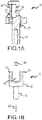
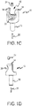
- Figures 1A-D illustrate various views of a bearing support 10 according to some embodiments of the present disclosure.
- the bearing support 10 generally includes a base 12, along with a pair of opposed and spaced projections 14 which establish a receiving area 16 therebetween.
- the bearing support 10 has a post or mounting post 18 which is received in a structural member (or other housing element) of a centrifuge (for example), and can include fixation means comprising a detent, screw or frictional fit (for example).
- the base 12 of the bearing support 10 can also include a dowel pin 20 which is affixed in a recess (alternatively, a projection can be machined/formed into the base 12), which is then received by the structural member to which the bearing support 10 is mounted (this can be used to allow the bearing support 10 to pivot a certain amount around a linear axis of the mounting post 18).
- a load bearing area 28 may be recessed such that an edge of a bearing is received therein.
- Other features which enable the efficient and speedy mounting of a bearing and/or tube-bearing combinations include one or more chamfers 26 and one or more "ramps", which may facilitate directing the bearing and/or tube into the receiving area 16 of the bearing support 10.
- the noted detent 24 e.g., ball detent
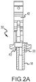
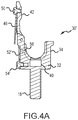
- Figures 2A-C , 3A-C , and 4A-C illustrate some embodiments of the present disclosure.
- the embodiments like those in Figures 1A-D , there is a post, two projections which create a receiving area, and a dowel pin/functionality.
- the embodiments include an arm which bridges the opening between the two projections and the receiving area (in some embodiments, it substantially bridges the opening).
- the arm may pivot on one projection, by means of a pin which is received in an opening on the projection, and may also be spring loaded via a spring (affixed via a bolt/rivet).
- a magnet which can be used to both help guide a bearing into the receiving area (and/or bearing recess therein), but may also provide an audible "click" which assures that the bearing is properly in place (the ball detent 24 noted above can perform a similar function).
- the bearing support 30 generally includes a base 32, a pair of opposed and spaced projections 34 which establish a receiving area 36 therebetween, along with the above-noted arrangement of a post 18 and pin 20.
- the bearing support 30 further includes a retaining arm 42 which bridges the opening or space between the upper portion of the two projections 34 and the receiving area 36.
- the retaining arm 42 may pivot on one projection 34, by means of a pin 48 which is received in an opening on the upper end of one of the projections 34, and may also be spring loaded via a spring 46 (affixed via an appropriate fastener 50).
- the bearing support 30 further includes a magnet aperture 38 in which a magnet 40 is positioned.
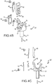
- Such embodiments as disclosed in Figures 3A-C , and 4A-C may also include a spring/arm lock, which insures that the arm bridging the receiving area is at least substantially locked into place. So as to be able to move the arm to, say, remove the bearing from the support, a release pin may also be included, which, when pressed (or pulled, depending upon how the pin is set up), releases the spring lock and allows the arm to open.
- a spring/arm lock So as to be able to move the arm to, say, remove the bearing from the support, a release pin may also be included, which, when pressed (or pulled, depending upon how the pin is set up), releases the spring lock and allows the arm to open.
- the bearing support 30' in accordance with the embodiments of Figures 3A-C includes corresponding features to those discussed above in relation to Figures 2A-C , along with a spring lock 52 that may be secured to one of the projections 34 by an appropriate fastener 54, and which insures that the retaining arm 42 bridging the receiving area 36 is at least substantially locked into place.
- a release pin 56 may also be included, which, when pressed (or pulled, depending upon how the pin 56 is set up), releases the spring lock 52 and allows the retaining arm 42 to open.
- the bearing support 30" in accordance with the embodiments of Figures 4A-C includes corresponding features to those discussed above in relation to Figures 2A-C , along with a different mechanism (from that disclosed in Figures 3A-C ) to retain the retaining arm 42 in a closed position, and that is in the form of a locking arm 52', associated fastener 54', and locking pin release 56'.
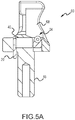
- Figures 5A-C illustrate yet other embodiments of the present disclosure.
- the bearing support 60 includes a base 62, two projections 64 housing a receiving area 66, and a load bearing area 68, where these projections 64 again are disposed in opposing relation and are spaced from one another.
- the bearing support 60 also utilizes the above-noted arrangement of a post 18 and pin 20.
- both a ball detent 24 (associated detent aperture 22) and a magnet 40 (associated magnet aperture 38) may be included, which either or both can serve to both guide and/or substantially affix the bearing in place within the bearing support 60, and/or may also be used for audible confirmation that the bearing is received.
- the bearing support 70 includes a base 72 and two projections 74 housing a receiving area 76, where these projections 74 again are disposed in opposing relation and are spaced from one another.
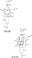
- the bearing support 70 also utilizes the above-noted arrangement of a post 18 and pin 20, along with magnet 40 and an associated magnet aperture 38. Additionally, these embodiments help illustrate a circumferential base support 78 which is configured to surround at least a portion of at least one of the projections 74.
- a bearing 90 is illustrated (which may be the same type, shape, and form of a bearing as may be used in earlier embodiments).
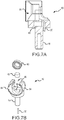
- Figures 7A-D show yet further embodiments according to the present disclosure. These embodiments are similar to those of Figures 5A-C and 6A-C .
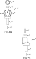
- the bearing support 80 includes a base 82 and two projections 84 housing a receiving area 86, where these projections 84 again are disposed in opposing relation and are spaced from one another.
- the bearing support 80 also utilizes the above-noted arrangement of a post 18 and pin 20, along with magnet 40 and an associated magnet aperture 38.
- the bearing support 80 also incorporates a ramp 88 (and/or a chamfer) which may be used to help guide the bearing 90 into the receiving area 86/bearing recess/ring.
- Figures 8A-8E illustrate yet another embodiment of a bearing support and that is identified by reference numeral 100.
- the bearing support 100 includes a base 102 and a pair of projections 104 that extend upwardly from the base 102 and that are spaced from one another in opposing relation to define a receiving area 112 for the bearing 90.
- the bearing support 100 also includes the above-noted arrangement of a post 106 and pin 108.
- the bearing support 100 is configured to require the bearing 90 to be positioned in the receiving area 112 only through an open loading end 110 of the bearing support 100.
- the bearing 90 cannot be directed into the receiving area 112 through the space between the upper portions of the projections 104 (e.g., the spacing between the upper portions of the projections 104 is smaller than the outer diameter of the bearing 90 for which the bearing support 100 is configured).
- the bearing 90 also cannot be directed into the receiving area 112 through an open non-loading end 120 of the bearing support 100 (the loading end 110 and the non-loading end 120 being directly opposite of one another).
- the bearing support 100 includes a protrusion or ledge 122 that is inwardly extending and that precludes the bearing 90 from being installed through the non-loading end 120.
- the loading end 110 of the bearing support 100 includes a pair of chamfered surfaces or ramps 118 (e.g., spherically-shaped).
- the ramps 118 are oriented to facilitate directing the bearing 90 into the receiving area 112 in alignment with a slot 114 that receives a lower portion of the bearing 90.
- These ramps 118 are subject to a number of characterizations.
- the ramps 118 may be described as at least generally converging toward each other progressing in the direction of the bearing slot 114, the receiving area 112, and/or the non-loading end 120.
- the ramps 118 may be described as being sloped in the direction of the bearing slot 114.
- each projection 104 may include a ramp 118 as described. These ramps 118 may be characterized as collectively defining an aperture. Based upon the configuration/orientation of the ramps 118, the effective diameter of this aperture is progressively reduced proceeding in the direction of the receiving area 112, the bearing slot 114, and/or the non-loading end 120.
- the ramp 118 on one projection 104 may be characterized as sloping in the direction of the opposite projection 104 proceeding in the direction of the bearing slot 114, the receiving area 112, and/or the non-loading end 120.
- a reference axis 124 may extend through a center of the loading end 110 and the non-loading end 120, and may be disposed parallel to the projections 104.
- Each ramp 118 may be characterized as converging toward this reference axis 124 proceeding in the direction of the receiving area 112, the bearing slot 114, and/or the non-loading end 120.
- a magnet aperture 116 (and thereby the magnet 40) is disposed below a portion of the bearing slot 114 (e.g., a central portion of the bearing slot 114).
- the magnet aperture 116 may be characterized as intersecting the bearing slot 114.
- the magnet 40 is positioned within this magnet aperture 116 and should generate a sufficient attractive force to pull the bearing 90 into the bearing slot 114 if the bearing 90 is not properly seated within the bearing slot 114 (e.g., when the bearing 90 is at least partially aligned with the bearing slot 114, but not properly seated within the bearing slot 114).
- a boundary for the receiving area 112 may be defined by interior surfaces of the two projections 104 and the surface that extends between the two projections 104 (collectively a "perimeter surface").
- the bearing slot 114 and the magnet aperture 116 each may be characterized as intersecting this perimeter surface.
- each of the bearing slot 114 and the magnet aperture 116 may be characterized as projecting toward the receiving area 112.
- the bearing 90 When the bearing 90 is disposed within the bearing slot 114, only a lower portion of the bearing 90 is actually disposed within the bearing slot 114 - an upper portion of the bearing 90 is disposed outside of the bearing slot 114 (e.g., the upper portion of the bearing 90 is not restrained within a slot). However, the portion of the bearing 90 that extends above the bearing slot 114 may be disposed against the ledge 122.
- the bearing support 100 of Figures 8A-8F may be installed on a rotating frame of a centrifuge system as will be discussed in more detail below.
- the resulting centrifugal forces experienced by the bearing support 100 and the ramps 118 may cooperate to direct the bearing 90 to the bearing slot 114.
- the magnet 40 should then exert a pulling force on the bearing 90 so as to become properly seated within the bearing slot 114.
- Figure 9 illustrates use of a bearing support/clamp according to some embodiments.
- Figure 9 may be characterized as being illustrative of a centrifuge system 200 that includes a frame 202 (e.g., a pair of drive tube arms), a bowl holder or bowl holding plate 204, and a centrifuge bowl 210 that is secured relative to the bowl holder 204 and that is rotated by a collective rotation of the frame 202 and bowl holder 204.
- a drive tube 208 extends from the top portion of the centrifuge bowl 206 and extends along a portion of the frame 202 (e.g., one of its drive tube arms).
- one or more supports/clamps 210 are positioned on the frame 202 (e.g., one of its drive-tube arms).
- a pair of bearings are mounted on the drive tube 208, and each of these bearings is received by the receiving area of the corresponding bearing support 210.
- the outer part of the bearing is held in place, while the inner part of the bearing may rotate with the drive tube 208 as the centrifuge bowl 206 spins or rotates.
- FIGS 9A and 9B present additional views relating to the centrifuge bowl system from Figure 9 .
- the centrifuge system 200 may include a centrifuge chamber 230 that is located within a casting or outer housing 220 of the centrifuge system 200.
- a rotational drive 240 is used to rotate the centrifuge bowl 206 about an axis 250 and when appropriately positioned in the centrifuge chamber 230.
- the rotational drive 240 may be of any appropriate type/configuration, for instance one capable of utilizing 1-omega 2-omega spin technology.
- bracket or frame 202 and bowl holding plate 204 are both disposed within the centrifuge chamber 230 and are rotated by the rotational drive 240.
- the lower portion of the centrifuge bowl 206 is disposed within and is detachably secured to the bowl holding plate 204.
- the noted conduit or drive tube 208 extends out of the upper portion of the centrifuge bowl 206, is secured to and rotates with the frame 202, and extends through the lower portion of the housing 220 and then out of the centrifuge chamber 230.
- Certain lines or tubes of a disposable photopheresis kit may be disposed within this drive tube 208 (e.g., a tube for directing whole blood into the centrifuge bowl 206; a tube for directing a lower density blood component, such as plasma and buffy coat, out of the centrifuge bowl 206; a tube for directing a higher density blood component, such as red blood cells, out of the centrifuge bowl 206).
- the rotational drive 240 rotates the frame 202 and the bowl holding plate 204, which in turn rotates the centrifuge bowl 206 relative to the housing 220 for the centrifuge chamber 230. Rotation of the centrifuge bowl 206 separates whole blood (within the centrifuge bowl 206) into a plurality of blood components within the centrifuge bowl 206, for instance plasma, buffy coat, and red blood cells.
- features from one and/or another disclosed embodiment may be interchangeable with features from other disclosed embodiments, which, in turn, correspond to yet other embodiments.
- one or more features/elements of disclosed embodiments may be removed and still result in patentable subject matter (and thus, resulting in yet more embodiments of the subject disclosure).
- patentable claims may include one or more negative limitations to indicate such lack of one or more featured taught in the prior art in, for example, any one or more of certain disclosed apparatuses, systems, and methods.
Landscapes
- Engineering & Computer Science (AREA)
- General Engineering & Computer Science (AREA)
- Mechanical Engineering (AREA)
- Centrifugal Separators (AREA)
- Clamps And Clips (AREA)
Description
- This patent application is a non-provisional patent application of and claims the benefit of copending
U.S. Provisional Patent Application Serial No. 62/157,309 - Embodiments of the present disclosure generally relate to apparatuses, systems and methods for supporting a tube or conduit for directing fluids into a centrifuge system.
- Centrifuges are used to separate a fluid into a plurality of fluid constituents by inducing a density gradient within the fluid. One known centrifuge configuration uses a disposable that includes a centrifuge bowl and a drive tube that extends from the top of the centrifuge bowl, where a plurality of separate conduits are disposed within this drive tube. Fluid may be directed into the centrifuge bowl through one of these conduits, and various fluid constituents may be removed from the centrifuge bowl through one or more of these conduits. In any case, this centrifuge bowl may be secured relative to a rotating frame, and the drive tube may be clamped or otherwise secured to the rotating frame during centrifuging.
-
EP2397228 A2 discloses a one-piece bearing for use with a fluid processing assembly of the type having an umbilicus, a liner received in the gimbal and the gimbal received in a bearing support including a gap to enable the umbilicus to be inserted into it from the side. - The principals and operations of the devices, methods and systems, according to some embodiments of the present disclosure, may be better understood with reference to the drawings, and the following description. These drawings are given for illustrative purposes only and are not meant to be limiting. The figures illustrate various embodiments.
-
Figures 1A-D are illustrations of a bearing support and/or clamp in cross-section, exploded front, exploded iso, and exploded side views, respectively, according to some embodiments. -
Figures 2A-C are illustrations of a bearing support and/or clamp in cross-section, exploded front, and exploded iso views, respectively, according to some embodiments. -
Figures 3A-C are illustrations of a bearing support and/or clamp in cross-section, exploded front, and exploded iso views, respectively, according to some embodiments. -
Figures 4A-C are illustrations of a bearing support and/or clamp in cross-section, exploded iso, and exploded front views, respectively, according to some embodiments. -
Figures 5A-C are illustrations of a bearing support and/or clamp in cross-section, exploded front, and exploded iso views, respectively, according to some embodiments. -
Figures 6A-C are illustrations of a bearing support and/or clamp in front, exploded iso, and exploded side views, respectively, according to some embodiments. -
Figures 7A-D are illustrations of a bearing support and/or clamp in cross-section, exploded iso, and exploded front and exploded side views, respectively, according to some embodiments. -
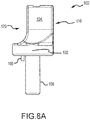
Figure 8A is a side view of another embodiment of a bearing support. -
Figure 8B is an end view of a loading end of the bearing support ofFigure 8A . -
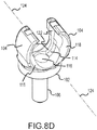
Figures 8C-8E are perspective views of the loading end of the bearing support ofFigure 8A , illustrating a bearing slot and/or magnet aperture that are located within a receiving area of the bearing support. -
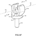
Figure 8F is a perspective view of a non-loading end of the bearing support ofFigure 8A . -
Figure 9 is an isometric view of a centrifuge system according to some embodiments. -
Figure 9A is another perspective view of a centrifuge system in accordance withFigure 9 . -
Figure 9B is a cutaway view of additional components of a centrifuge system in accordance withFigure 9 . - According to the invention there is provided a bearing support or a support and/or clamp according to claim 1 or claim 16. Optional features are recited in the dependent claims.
- Some embodiments may include one and/or another of the following features/functionality:
- the receiving area of such a support may be configured to removably receive the object;
- upon the at least one of the detent and magnet being configured to retain the object within the receiving area, such configuration corresponds to temporary retention of the object within the receiving area;
- a lockout means, where, in some embodiments, the lockout means comprises a locking arm configured to substantially bridge the distance between the two receiving members upon the object being received, such that the object is locked within the receiving area;
- the locking arm, noted above, may removably lock the object within the the receiving area;
- the locking arm, noted above, may include a first end which pivots relative to one of the receiving members and a second end which removably locks in or on the other of the receiving members;
- a circumferential support member configured to surround at least a portion of at least one of the base and one and/or another of the receiving members;
- at least one of a chamfer and ramp provided on at least one of the base,
and one and/or another of the receiving members, the chamfer and
ramp being configured to aid in the loading of the object in the receiving area; - the object may be a bearing;
- the base may include or comprise a post configured for being received in an opening;
- a recess arranged within the base to receive a guide pin; and
- a guide pin projecting from the base for receipt within a recess of a structure.
- In some examples, a centrifuge system is provided which may comprise a centrifuge bowl configured to spin along a central axis, a tube projecting from the center of the centrifuge bowl initially along the central axis, at least one bearing arranged along the tube, where the tube is configured to be arranged within the center of the bearing, a support arm or structure surrounding at least a portion of the container, and at least one support according to one and/or another of embodiments and arranged on at least the support arm. Each of the at least one supports is configured to receive at least one of the tube and bearing such that, upon rotation of bowl, the tube rotates within the bearing, the outer portion of the bearing being affixed to the support.
- In some examples, a method for connecting a tube within a centrifuge system is provided and comprises providing a centrifuge system having a centrifuge bowl, providing a tube having arranged thereon at least one bearing arranged thereon, providing a support in accordance with the foregoing, aligning each bearing to the side of the ramp and/or chamfer of the support, and pushing and/or pulling each bearing into the receiving area, such that, a side of the bearing rides along the ramp and/or chamfer until the edge of the bearing is received within the receiving area.
-
Figures 1A-D illustrate various views of abearing support 10 according to some embodiments of the present disclosure. As shown, thebearing support 10 generally includes abase 12, along with a pair of opposed and spacedprojections 14 which establish areceiving area 16 therebetween. Thebearing support 10 has a post or mountingpost 18 which is received in a structural member (or other housing element) of a centrifuge (for example), and can include fixation means comprising a detent, screw or frictional fit (for example). - The
base 12 of thebearing support 10 can also include adowel pin 20 which is affixed in a recess (alternatively, a projection can be machined/formed into the base 12), which is then received by the structural member to which thebearing support 10 is mounted (this can be used to allow thebearing support 10 to pivot a certain amount around a linear axis of the mounting post 18). - A
load bearing area 28 may be recessed such that an edge of a bearing is received therein. Other features which enable the efficient and speedy mounting of a bearing and/or tube-bearing combinations include one ormore chamfers 26 and one or more "ramps", which may facilitate directing the bearing and/or tube into thereceiving area 16 of thebearing support 10. The noted detent 24 (e.g., ball detent) may be used to aid in locking/retaining the bearing in place within thebearing support 10, and may be disposed within adetent aperture 22 of thebearing support 10. -
Figures 2A-C ,3A-C , and4A-C , illustrate some embodiments of the present disclosure. In these embodiments, like those inFigures 1A-D , there is a post, two projections which create a receiving area, and a dowel pin/functionality. In addition, the embodiments include an arm which bridges the opening between the two projections and the receiving area (in some embodiments, it substantially bridges the opening). The arm may pivot on one projection, by means of a pin which is received in an opening on the projection, and may also be spring loaded via a spring (affixed via a bolt/rivet). Further features include a magnet which can be used to both help guide a bearing into the receiving area (and/or bearing recess therein), but may also provide an audible "click" which assures that the bearing is properly in place (theball detent 24 noted above can perform a similar function). - In the embodiments of
Figures 2A-C , thebearing support 30 generally includes abase 32, a pair of opposed and spacedprojections 34 which establish areceiving area 36 therebetween, along with the above-noted arrangement of apost 18 andpin 20. Thebearing support 30 further includes aretaining arm 42 which bridges the opening or space between the upper portion of the twoprojections 34 and thereceiving area 36. Theretaining arm 42 may pivot on oneprojection 34, by means of apin 48 which is received in an opening on the upper end of one of theprojections 34, and may also be spring loaded via a spring 46 (affixed via an appropriate fastener 50). Thebearing support 30 further includes amagnet aperture 38 in which amagnet 40 is positioned. - Such embodiments as disclosed in
Figures 3A-C , and4A-C , may also include a spring/arm lock, which insures that the arm bridging the receiving area is at least substantially locked into place. So as to be able to move the arm to, say, remove the bearing from the support, a release pin may also be included, which, when pressed (or pulled, depending upon how the pin is set up), releases the spring lock and allows the arm to open. Various aspects of such embodiments are illustrated inFigures 4A-C . - The bearing support 30' in accordance with the embodiments of
Figures 3A-C includes corresponding features to those discussed above in relation toFigures 2A-C , along with aspring lock 52 that may be secured to one of theprojections 34 by anappropriate fastener 54, and which insures that the retainingarm 42 bridging the receivingarea 36 is at least substantially locked into place. So as to be able to move the retainingarm 42 to, say, remove a bearing from the bearing support 30', arelease pin 56 may also be included, which, when pressed (or pulled, depending upon how thepin 56 is set up), releases thespring lock 52 and allows the retainingarm 42 to open. - The bearing
support 30" in accordance with the embodiments ofFigures 4A-C includes corresponding features to those discussed above in relation toFigures 2A-C , along with a different mechanism (from that disclosed inFigures 3A-C ) to retain the retainingarm 42 in a closed position, and that is in the form of a locking arm 52', associated fastener 54', and locking pin release 56'. -
Figures 5A-C illustrate yet other embodiments of the present disclosure. In such embodiments, similar to those described and illustrated earlier, the bearingsupport 60 includes abase 62, twoprojections 64 housing a receivingarea 66, and aload bearing area 68, where theseprojections 64 again are disposed in opposing relation and are spaced from one another. The bearingsupport 60 also utilizes the above-noted arrangement of apost 18 andpin 20. However, in these embodiments, both a ball detent 24 (associated detent aperture 22) and a magnet 40 (associated magnet aperture 38) may be included, which either or both can serve to both guide and/or substantially affix the bearing in place within the bearingsupport 60, and/or may also be used for audible confirmation that the bearing is received. - The embodiments shown in
Figures 6A-C are yet further embodiments of the support and include similar features and functionality as those described in earlier embodiments. In such embodiments, similar to those described and illustrated earlier, the bearingsupport 70 includes a base 72 and twoprojections 74 housing a receivingarea 76, where theseprojections 74 again are disposed in opposing relation and are spaced from one another. The bearingsupport 70 also utilizes the above-noted arrangement of apost 18 andpin 20, along withmagnet 40 and an associatedmagnet aperture 38. Additionally, these embodiments help illustrate acircumferential base support 78 which is configured to surround at least a portion of at least one of theprojections 74. Additionally, in these embodiments, abearing 90 is illustrated (which may be the same type, shape, and form of a bearing as may be used in earlier embodiments). -
Figures 7A-D show yet further embodiments according to the present disclosure. These embodiments are similar to those ofFigures 5A-C and6A-C . In this regard, the bearingsupport 80 includes a base 82 and twoprojections 84 housing a receivingarea 86, where theseprojections 84 again are disposed in opposing relation and are spaced from one another. The bearingsupport 80 also utilizes the above-noted arrangement of apost 18 andpin 20, along withmagnet 40 and an associatedmagnet aperture 38. The bearingsupport 80 also incorporates a ramp 88 (and/or a chamfer) which may be used to help guide thebearing 90 into the receivingarea 86/bearing recess/ring. -
Figures 8A-8E illustrate yet another embodiment of a bearing support and that is identified byreference numeral 100. Thebearing support 100 includes abase 102 and a pair ofprojections 104 that extend upwardly from thebase 102 and that are spaced from one another in opposing relation to define a receivingarea 112 for thebearing 90. Thebearing support 100 also includes the above-noted arrangement of apost 106 andpin 108. - The
bearing support 100 is configured to require thebearing 90 to be positioned in the receivingarea 112 only through anopen loading end 110 of thebearing support 100. The bearing 90 cannot be directed into the receivingarea 112 through the space between the upper portions of the projections 104 (e.g., the spacing between the upper portions of theprojections 104 is smaller than the outer diameter of thebearing 90 for which thebearing support 100 is configured). The bearing 90 also cannot be directed into the receivingarea 112 through an opennon-loading end 120 of the bearing support 100 (theloading end 110 and thenon-loading end 120 being directly opposite of one another). In this regard, thebearing support 100 includes a protrusion orledge 122 that is inwardly extending and that precludes the bearing 90 from being installed through thenon-loading end 120. - The
loading end 110 of thebearing support 100 includes a pair of chamfered surfaces or ramps 118 (e.g., spherically-shaped). Generally, theramps 118 are oriented to facilitate directing thebearing 90 into the receivingarea 112 in alignment with aslot 114 that receives a lower portion of thebearing 90. Theseramps 118 are subject to a number of characterizations. Theramps 118 may be described as at least generally converging toward each other progressing in the direction of thebearing slot 114, the receivingarea 112, and/or thenon-loading end 120. Theramps 118 may be described as being sloped in the direction of thebearing slot 114. - An end surface of each
projection 104 may include aramp 118 as described. Theseramps 118 may be characterized as collectively defining an aperture. Based upon the configuration/orientation of theramps 118, the effective diameter of this aperture is progressively reduced proceeding in the direction of the receivingarea 112, thebearing slot 114, and/or thenon-loading end 120. Theramp 118 on oneprojection 104 may be characterized as sloping in the direction of theopposite projection 104 proceeding in the direction of thebearing slot 114, the receivingarea 112, and/or thenon-loading end 120. Areference axis 124 may extend through a center of theloading end 110 and thenon-loading end 120, and may be disposed parallel to theprojections 104. Eachramp 118 may be characterized as converging toward thisreference axis 124 proceeding in the direction of the receivingarea 112, thebearing slot 114, and/or thenon-loading end 120. - A magnet aperture 116 (and thereby the magnet 40) is disposed below a portion of the bearing slot 114 (e.g., a central portion of the bearing slot 114). As such, the
magnet aperture 116 may be characterized as intersecting thebearing slot 114. Themagnet 40 is positioned within thismagnet aperture 116 and should generate a sufficient attractive force to pull thebearing 90 into thebearing slot 114 if thebearing 90 is not properly seated within the bearing slot 114 (e.g., when thebearing 90 is at least partially aligned with thebearing slot 114, but not properly seated within the bearing slot 114). A boundary for the receivingarea 112 may be defined by interior surfaces of the twoprojections 104 and the surface that extends between the two projections 104 (collectively a "perimeter surface"). Thebearing slot 114 and themagnet aperture 116 each may be characterized as intersecting this perimeter surface. Moreover, each of thebearing slot 114 and themagnet aperture 116 may be characterized as projecting toward the receivingarea 112. - When the
bearing 90 is disposed within thebearing slot 114, only a lower portion of thebearing 90 is actually disposed within the bearing slot 114 - an upper portion of thebearing 90 is disposed outside of the bearing slot 114 (e.g., the upper portion of thebearing 90 is not restrained within a slot). However, the portion of thebearing 90 that extends above thebearing slot 114 may be disposed against theledge 122. - The
bearing support 100 ofFigures 8A-8F may be installed on a rotating frame of a centrifuge system as will be discussed in more detail below. In the event that thebearing 90 is not properly seated within thebearing slot 114 when centrifuging is initiated, the resulting centrifugal forces experienced by thebearing support 100 and theramps 118 may cooperate to direct thebearing 90 to thebearing slot 114. Themagnet 40 should then exert a pulling force on thebearing 90 so as to become properly seated within thebearing slot 114. -
Figure 9 illustrates use of a bearing support/clamp according to some embodiments.Figure 9 may be characterized as being illustrative of acentrifuge system 200 that includes a frame 202 (e.g., a pair of drive tube arms), a bowl holder orbowl holding plate 204, and acentrifuge bowl 210 that is secured relative to thebowl holder 204 and that is rotated by a collective rotation of theframe 202 andbowl holder 204. Adrive tube 208 extends from the top portion of thecentrifuge bowl 206 and extends along a portion of the frame 202 (e.g., one of its drive tube arms). As shown, one or more supports/clamps 210 (e.g., in accordance with any of the foregoing bearing support embodiments) are positioned on the frame 202 (e.g., one of its drive-tube arms). A pair of bearings are mounted on thedrive tube 208, and each of these bearings is received by the receiving area of the correspondingbearing support 210. The outer part of the bearing is held in place, while the inner part of the bearing may rotate with thedrive tube 208 as thecentrifuge bowl 206 spins or rotates. -
Figures 9A and9B present additional views relating to the centrifuge bowl system fromFigure 9 . Thecentrifuge system 200 may include acentrifuge chamber 230 that is located within a casting orouter housing 220 of thecentrifuge system 200. Arotational drive 240 is used to rotate thecentrifuge bowl 206 about anaxis 250 and when appropriately positioned in thecentrifuge chamber 230. Therotational drive 240 may be of any appropriate type/configuration, for instance one capable of utilizing 1-omega 2-omega spin technology. - The above-noted bracket or
frame 202 andbowl holding plate 204 are both disposed within thecentrifuge chamber 230 and are rotated by therotational drive 240. The lower portion of thecentrifuge bowl 206 is disposed within and is detachably secured to thebowl holding plate 204. The noted conduit or drivetube 208 extends out of the upper portion of thecentrifuge bowl 206, is secured to and rotates with theframe 202, and extends through the lower portion of thehousing 220 and then out of thecentrifuge chamber 230. Certain lines or tubes of a disposable photopheresis kit may be disposed within this drive tube 208 (e.g., a tube for directing whole blood into thecentrifuge bowl 206; a tube for directing a lower density blood component, such as plasma and buffy coat, out of thecentrifuge bowl 206; a tube for directing a higher density blood component, such as red blood cells, out of the centrifuge bowl 206). Therotational drive 240 rotates theframe 202 and thebowl holding plate 204, which in turn rotates thecentrifuge bowl 206 relative to thehousing 220 for thecentrifuge chamber 230. Rotation of thecentrifuge bowl 206 separates whole blood (within the centrifuge bowl 206) into a plurality of blood components within thecentrifuge bowl 206, for instance plasma, buffy coat, and red blood cells. - Any and all references to publications or other documents, including but not limited to, patents, patent applications, articles, webpages, books, etc., presented anywhere in the present application, are herein incorporated by reference in their entirety.
- Example embodiments of the devices, systems and methods have been described herein. As may be noted elsewhere, these embodiments have been described for illustrative purposes only and are not limiting. Other embodiments are possible and are covered by the disclosure, which will be apparent from the teachings contained herein. Thus, the breadth and scope of the disclosure should not be limited by any of the above-described embodiments but should be defined only in accordance with claims supported by the present disclosure and their equivalents. Moreover, embodiments of the subject disclosure may include methods, systems and devices which may further include any and all elements/features from any other disclosed methods, systems, and devices, including any and all features corresponding to bearing support. In other words, features from one and/or another disclosed embodiment may be interchangeable with features from other disclosed embodiments, which, in turn, correspond to yet other embodiments. Furthermore, one or more features/elements of disclosed embodiments may be removed and still result in patentable subject matter (and thus, resulting in yet more embodiments of the subject disclosure). Also within the scope of some of the embodiments of the present disclosure is the specific lack of one or more features that may be present in the prior art. In such embodiments, patentable claims may include one or more negative limitations to indicate such lack of one or more featured taught in the prior art in, for example, any one or more of certain disclosed apparatuses, systems, and methods.
Claims (16)
- A bearing support (10; 20; 30; 40; 50; 60; 70; 80), comprising:a base (12; 32; 62);a first open end and an oppositely disposed second open end, wherein a first reference axis extends through said bearing support between said first open end and said second open end;a pair of projections (14; 34; 64; 74; 84) that extend upwardly from said base and that are disposed in opposing and spaced relation to one another, wherein each projection of said pair is disposed on an opposite side of said first reference axis, and wherein upper portions of said projections of said pair are separated from one another by an open space;a receiving area (16; 36; 66) between said pair of projections;a magnet aperture (38) that projects toward said receiving area; anda magnet (40) disposed in said magnet aperture.
- The bearing support (10; 20; 30; 40; 50; 60; 70; 80) of claim 1, wherein said magnet (40) is located between said pair of projections (14; 34; 64; 74; 84).
- The bearing support (10; 20; 30; 40; 50; 60; 70; 80) of any of claims 1-2, further comprising:
a perimeter surface that defines a boundary of said receiving area, wherein said perimeter surface comprises an interior surface of each projection of said pair of projections (14; 34; 64; 74; 84), and wherein said magnet aperture (38) is located on a portion of said perimeter surface that extends between said pair of projections. - The bearing support (10; 20; 30; 40; 50; 60; 70; 80) of any of claims 1-3, wherein said open space is smaller than an outer diameter of a bearing for which said bearing support is configured and said bearing support is configured to only allow the bearing to be directed into said receiving area through said first open end.
- The bearing support (10; 20; 30; 40; 50; 60; 70; 80) of any of claims 1-4, wherein end surfaces of said pair of projections (14; 34; 64; 74; 84) collectively define an aperture that extends toward said receiving area, wherein an effective diameter of said aperture is progressively reduced in proceeding in a direction of said receiving area.
- The bearing support (10; 20; 30; 40; 50; 60; 70; 80) of claim 5, wherein said end surface of each said projection of said pair of projections (14; 34; 64; 74; 84) is spherically-shaped.
- The bearing support (10; 20; 30; 40; 50; 60; 70; 80) of any of claims 1-6, wherein said receiving area (16; 36; 66) is further located between said first open end and said second open end, wherein said first reference axis extends through a center of said first open end and a center of said second open end, wherein said first reference axis is parallel to said pair of projections (14; 34; 64; 74; 84), and wherein said bearing support comprises a first surface that slopes toward said first reference axis in proceeding from said first open end toward said second open end.
- The bearing support (10; 20; 30; 40; 50; 60; 70; 80) of any of claims 1-7, further comprising a bearing slot.
- The bearing support (10; 20; 30; 40; 50; 60; 70; 80) of claim 8, wherein said magnet aperture (38) is aligned with and intersects said bearing slot, and wherein said magnet is positioned below said bearing slot.
- The bearing support (10; 20; 30; 40; 50; 60; 70; 80) of any of claims 8-9, wherein said bearing slot is located between said first and second projections.
- The bearing support (10; 20; 30; 40; 50; 60; 70; 80) of any of claims 8-10, wherein said bearing support further comprises a perimeter surface that defines a boundary of said receiving area, wherein said perimeter surface comprises an interior surface of each projection of said pair of projections (14; 34; 64; 74; 84), and wherein said bearing slot is located on a portion of said perimeter surface that extends between said pair of projections.
- A bearing assembly comprising a bearing and the bearing support (10; 20; 30; 40; 50; 60; 70; 80) of any of claims 8-11, wherein only a lower portion of said bearing is disposed in said bearing slot such an upper portion of said bearing is disposed outside of said bearing slot.
- The bearing assembly of claim 12, wherein said bearing support (10; 20; 30; 40; 50; 60; 70; 80) further comprises a ledge, wherein a back side of said upper portion of said bearing is disposed against said ledge, and wherein said ledge precludes said bearing from being directed into said receiving area through said second open end.
- The bearing assembly of claim 12 or claim 13, wherein said bearing support (10; 20; 30; 40; 50; 60; 70; 80) further comprises a mounting post, wherein said pair of projections (14; 34; 64; 74; 84) extend from one side of said base and said mounting post extends from an opposite side of said base.
- A centrifuge system (200), comprising:a frame (202);a centrifuge bowl (206) interconnected and rotatable in conjunction with said frame;a tube (208) extending from said centrifuge bowl; anda first bearing, wherein said tube extends through said first bearing, and wherein said first bearing is disposed within the bearing support (10; 20; 30; 40; 50; 60; 70; 80) of any of claims 1-11, and wherein the bearing support is mounted to said frame.
- A support and/or clamp (10; 20; 30; 40; 50; 60; 70; 80) for receiving a cylindrical element comprising:a base (12; 32; 62);a pair of opposed receiving members (14; 34; 64; 74; 84) projecting from the base and spaced apart from one another to establish a receiving area (16; 36; 66) configured with a size and shape to receive at least one of a circular, cylindrical and spherical object therein;at least one of a detent (24) and magnet (40) arranged within at least a portion of the receiving area, the detent and/or magnet configured to at least one of retain the object within the receiving area and establish a sound associated with the receiving of the object;at least one of a chamfer and ramp provided on at least one of the base, and one and/or another of the receiving members;a first open end and a second open end that are oppositely disposed; anda reference axis extending through a center of the first and second open ends, wherein the chamfer and ramp are configured to facilitate loading of the object along the reference axis for receipt in the receiving area.
Applications Claiming Priority (2)
| Application Number | Priority Date | Filing Date | Title |
|---|---|---|---|
| US201562157309P | 2015-05-05 | 2015-05-05 | |
| PCT/US2016/031007 WO2016179404A1 (en) | 2015-05-05 | 2016-05-05 | Support for centrifuge tubing |
Publications (2)
| Publication Number | Publication Date |
|---|---|
| EP3291918A1 EP3291918A1 (en) | 2018-03-14 |
| EP3291918B1 true EP3291918B1 (en) | 2019-04-17 |
Family
ID=56072428
Family Applications (1)
| Application Number | Title | Priority Date | Filing Date |
|---|---|---|---|
| EP16724781.6A Active EP3291918B1 (en) | 2015-05-05 | 2016-05-05 | Support for centrifuge tubing |
Country Status (7)
| Country | Link |
|---|---|
| US (1) | US10641415B2 (en) |
| EP (1) | EP3291918B1 (en) |
| JP (2) | JP6561202B2 (en) |
| BR (1) | BR112017023336B1 (en) |
| CA (1) | CA2984105C (en) |
| ES (1) | ES2728569T3 (en) |
| WO (1) | WO2016179404A1 (en) |
Families Citing this family (1)
| Publication number | Priority date | Publication date | Assignee | Title |
|---|---|---|---|---|
| WO2017070585A1 (en) | 2015-10-23 | 2017-04-27 | Novartis Ag | Method of scoring a sample comprising tumor tissue |
Family Cites Families (28)
| Publication number | Priority date | Publication date | Assignee | Title |
|---|---|---|---|---|
| US2271336A (en) * | 1940-11-27 | 1942-01-27 | Atlantic Refining Co | Bearing mounting |
| CH549988A (en) * | 1972-06-16 | 1974-06-14 | Bratschi Silent Gliss | FASTENING DEVICE. |
| DE7224033U (en) * | 1972-06-27 | 1972-10-12 | Heraeus-Christ Gmbh | SMALL CENTRIFUGE |
| US4079882A (en) * | 1977-03-18 | 1978-03-21 | Kabushiki Kaisha Kubota Seisakusho | Vibration-isolating apparatus for a centrifuge |
| JPS5453772U (en) * | 1977-09-24 | 1979-04-13 | ||
| ES240751Y (en) * | 1979-01-15 | 1979-08-16 | RETAINING DEVICE. | |
| US4822331A (en) * | 1987-11-09 | 1989-04-18 | Taylor David C | Centrifuge |
| NO176370C (en) * | 1992-08-25 | 1995-03-22 | Christensen As Ing Finn | Fixing device for attaching pipes to the substrate |
| US5336179A (en) * | 1993-06-01 | 1994-08-09 | Ryan Richard M | Line organizer |
| US5566919A (en) * | 1994-10-13 | 1996-10-22 | Norfolk Scientific, Inc. | Motor mount for reducing vibration and noise and method of using thereof |
| US5676339A (en) * | 1995-03-13 | 1997-10-14 | Simon; Hans | Easily removable cable strain relief device |
| US6344020B1 (en) * | 1997-04-11 | 2002-02-05 | Baxter International Inc. | Bearing and umbilicus gimbal with bearing retainer in blood processing system |
| US5989177A (en) * | 1997-04-11 | 1999-11-23 | Baxter International Inc. | Umbilicus gimbal with bearing retainer |
| JP3524852B2 (en) | 2000-08-23 | 2004-05-10 | 株式会社キャットアイ | Magnet mounting structure |
| US6669150B2 (en) * | 2001-05-31 | 2003-12-30 | Illinois Tool Works Inc. | Clip assembly with positive locating features |
| US6502794B1 (en) * | 2001-06-18 | 2003-01-07 | Tzu-Kuang Ting | Hanger device with suction cup |
| US6561206B1 (en) * | 2001-08-03 | 2003-05-13 | Christopher M. Wilkinson | Crutch coupling system |
| US7798333B2 (en) * | 2005-09-02 | 2010-09-21 | Roush Life Sciences, Llc | Systems, apparatus and methods for vacuum filtration |
| US7699277B2 (en) * | 2007-03-02 | 2010-04-20 | Gary Wayne Bagnall | Magnetic attachment apparatus |
| DE102007011194B3 (en) * | 2007-03-06 | 2008-09-04 | Winkler, Wolfram, Dipl.-Ing. Dr. | Locating clip for pipes in under-floor central heating system has two sets of jaws separated by a wire insertion gap |
| US8403278B1 (en) * | 2007-11-09 | 2013-03-26 | Spechtech, Inc. | Magnetic portable firearm or sporting instrument holding device |
| IT1399452B1 (en) * | 2010-04-15 | 2013-04-19 | Skudelny | SUPPORT DEVICE FOR SCHNORCHEL |
| US20110297797A1 (en) * | 2010-06-02 | 2011-12-08 | Yelverton Forrest D | Adjustable cable stop |
| US8277369B2 (en) * | 2010-06-15 | 2012-10-02 | Fenwal, Inc. | Bearing and bearing assembly for umbilicus of a fluid processing system |
| US8550235B2 (en) | 2010-07-12 | 2013-10-08 | Bunting Magnetics Co. | Magnetic fastening assembly for attaching a ferrous metal baking pan to a baking rack |
| US8900196B2 (en) * | 2011-04-21 | 2014-12-02 | C. R. Bard, Inc. | Anchoring system |
| US8647505B2 (en) * | 2011-06-24 | 2014-02-11 | The Western States Machine Company | Screen clamp with integrated center feed |
| US20150090845A1 (en) * | 2013-09-30 | 2015-04-02 | Covidien Lp | Medical Device Supporting Apparatus |
-
2016
- 2016-05-05 WO PCT/US2016/031007 patent/WO2016179404A1/en not_active Ceased
- 2016-05-05 ES ES16724781T patent/ES2728569T3/en active Active
- 2016-05-05 EP EP16724781.6A patent/EP3291918B1/en active Active
- 2016-05-05 BR BR112017023336-3A patent/BR112017023336B1/en active IP Right Grant
- 2016-05-05 JP JP2018510321A patent/JP6561202B2/en active Active
- 2016-05-05 CA CA2984105A patent/CA2984105C/en active Active
- 2016-05-05 US US15/570,996 patent/US10641415B2/en active Active
-
2019
- 2019-02-27 JP JP2019034263A patent/JP2019084532A/en active Pending
Non-Patent Citations (1)
| Title |
|---|
| None * |
Also Published As
| Publication number | Publication date |
|---|---|
| EP3291918A1 (en) | 2018-03-14 |
| US10641415B2 (en) | 2020-05-05 |
| JP6561202B2 (en) | 2019-08-14 |
| CA2984105A1 (en) | 2016-11-10 |
| BR112017023336B1 (en) | 2021-08-10 |
| US20180299030A1 (en) | 2018-10-18 |
| ES2728569T3 (en) | 2019-10-25 |
| CA2984105C (en) | 2020-04-28 |
| JP2018521284A (en) | 2018-08-02 |
| JP2019084532A (en) | 2019-06-06 |
| BR112017023336A2 (en) | 2018-07-24 |
| WO2016179404A1 (en) | 2016-11-10 |
Similar Documents
| Publication | Publication Date | Title |
|---|---|---|
| JP6571637B2 (en) | Head assembly for supporting and adjusting the position of an optical or electronic device | |
| US20250375223A1 (en) | Apparatus and Method for Limiting a Range of Angular Positions of a Screw | |
| US10099228B2 (en) | Apparatus for performing counter flow centrifugation and method of using same | |
| US9849551B2 (en) | Tool gripping mechanism | |
| US9127680B2 (en) | Verification of magnetic balance for magnetically levitated impeller | |
| EP0929363B1 (en) | Umbilicus gimbal with bearing retainer | |
| CN107223192B (en) | Pan-tilt mounting and dismounting mechanism and photographing device with the same | |
| JP2015150560A (en) | Driving head for detachably connecting drive unit of centrifugal separator to rotor, kit with driving head, and centrifugal separator | |
| CN101662708A (en) | Sound box bracket | |
| US10641415B2 (en) | Support for centrifuge tubing | |
| US20170368516A1 (en) | Mixing apparatus and method for mixing fluid in a vessel | |
| CN107072863A (en) | Assembly device for hanger arrangement and assembly system with assembly device | |
| CN109312568A (en) | Anchor for a vertical formwork and vertical formwork | |
| JP2022508170A (en) | Display screen stand and mounting system | |
| US6416455B1 (en) | Rotor for centrifuge having a specimen holder that accomodates an increased number of specimens | |
| CN101027605A (en) | Fixing device for fixing cameras and other optical devices to stands or for connection to other accessories | |
| EP2524733A1 (en) | Apparatus for performing a centrifugal field-flow fractionation, wedge design for use in such an apparatus and method of making such an apparatus and a rotor designed for use in such an apparatus | |
| CN214716734U (en) | Fixing device of rotary centrifugal microfluidic reagent disk | |
| US11779936B2 (en) | Centrifuge safety mechanism | |
| EP2635817B1 (en) | Temporary suspension element, and attachment and disassembly methods using said element | |
| US9545637B2 (en) | Bearing for umbilicus of a fluid processing system | |
| CN214420709U (en) | Quick-loading structure | |
| CN114193366B (en) | Laminar flow fan and rotation alignment method of laminar flow fan | |
| CN112827520A (en) | A fixing device for rotating centrifugal microfluidic reagent disc | |
| RU2115517C1 (en) | Multipurpose clamping device |
Legal Events
| Date | Code | Title | Description |
|---|---|---|---|
| STAA | Information on the status of an ep patent application or granted ep patent |
Free format text: STATUS: THE INTERNATIONAL PUBLICATION HAS BEEN MADE |
|
| PUAI | Public reference made under article 153(3) epc to a published international application that has entered the european phase |
Free format text: ORIGINAL CODE: 0009012 |
|
| STAA | Information on the status of an ep patent application or granted ep patent |
Free format text: STATUS: REQUEST FOR EXAMINATION WAS MADE |
|
| 17P | Request for examination filed |
Effective date: 20171201 |
|
| AK | Designated contracting states |
Kind code of ref document: A1 Designated state(s): AL AT BE BG CH CY CZ DE DK EE ES FI FR GB GR HR HU IE IS IT LI LT LU LV MC MK MT NL NO PL PT RO RS SE SI SK SM TR |
|
| AX | Request for extension of the european patent |
Extension state: BA ME |
|
| DAV | Request for validation of the european patent (deleted) | ||
| DAX | Request for extension of the european patent (deleted) | ||
| GRAP | Despatch of communication of intention to grant a patent |
Free format text: ORIGINAL CODE: EPIDOSNIGR1 |
|
| STAA | Information on the status of an ep patent application or granted ep patent |
Free format text: STATUS: GRANT OF PATENT IS INTENDED |
|
| RIC1 | Information provided on ipc code assigned before grant |
Ipc: B04B 5/04 20060101AFI20180925BHEP Ipc: F16C 35/067 20060101ALI20180925BHEP Ipc: F16L 3/16 20060101ALI20180925BHEP |
|
| INTG | Intention to grant announced |
Effective date: 20181017 |
|
| GRAS | Grant fee paid |
Free format text: ORIGINAL CODE: EPIDOSNIGR3 |
|
| GRAJ | Information related to disapproval of communication of intention to grant by the applicant or resumption of examination proceedings by the epo deleted |
Free format text: ORIGINAL CODE: EPIDOSDIGR1 |
|
| GRAL | Information related to payment of fee for publishing/printing deleted |
Free format text: ORIGINAL CODE: EPIDOSDIGR3 |
|
| STAA | Information on the status of an ep patent application or granted ep patent |
Free format text: STATUS: REQUEST FOR EXAMINATION WAS MADE |
|
| GRAR | Information related to intention to grant a patent recorded |
Free format text: ORIGINAL CODE: EPIDOSNIGR71 |
|
| STAA | Information on the status of an ep patent application or granted ep patent |
Free format text: STATUS: GRANT OF PATENT IS INTENDED |
|
| GRAA | (expected) grant |
Free format text: ORIGINAL CODE: 0009210 |
|
| STAA | Information on the status of an ep patent application or granted ep patent |
Free format text: STATUS: THE PATENT HAS BEEN GRANTED |
|
| INTG | Intention to grant announced |
Effective date: 20190307 |
|
| AK | Designated contracting states |
Kind code of ref document: B1 Designated state(s): AL AT BE BG CH CY CZ DE DK EE ES FI FR GB GR HR HU IE IS IT LI LT LU LV MC MK MT NL NO PL PT RO RS SE SI SK SM TR |
|
| REG | Reference to a national code |
Ref country code: GB Ref legal event code: FG4D |
|
| RAP2 | Party data changed (patent owner data changed or rights of a patent transferred) |
Owner name: MALLINCKRODT HOSPITAL PRODUCTS IP LIMITED |
|
| REG | Reference to a national code |
Ref country code: CH Ref legal event code: EP |
|
| REG | Reference to a national code |
Ref country code: DE Ref legal event code: R096 Ref document number: 602016012581 Country of ref document: DE |
|
| REG | Reference to a national code |
Ref country code: AT Ref legal event code: REF Ref document number: 1120971 Country of ref document: AT Kind code of ref document: T Effective date: 20190515 Ref country code: IE Ref legal event code: FG4D |
|
| REG | Reference to a national code |
Ref country code: NL Ref legal event code: MP Effective date: 20190417 |
|
| REG | Reference to a national code |
Ref country code: LT Ref legal event code: MG4D |
|
| PG25 | Lapsed in a contracting state [announced via postgrant information from national office to epo] |
Ref country code: NL Free format text: LAPSE BECAUSE OF FAILURE TO SUBMIT A TRANSLATION OF THE DESCRIPTION OR TO PAY THE FEE WITHIN THE PRESCRIBED TIME-LIMIT Effective date: 20190417 |
|
| REG | Reference to a national code |
Ref country code: ES Ref legal event code: FG2A Ref document number: 2728569 Country of ref document: ES Kind code of ref document: T3 Effective date: 20191025 |
|
| PG25 | Lapsed in a contracting state [announced via postgrant information from national office to epo] |
Ref country code: SE Free format text: LAPSE BECAUSE OF FAILURE TO SUBMIT A TRANSLATION OF THE DESCRIPTION OR TO PAY THE FEE WITHIN THE PRESCRIBED TIME-LIMIT Effective date: 20190417 Ref country code: PT Free format text: LAPSE BECAUSE OF FAILURE TO SUBMIT A TRANSLATION OF THE DESCRIPTION OR TO PAY THE FEE WITHIN THE PRESCRIBED TIME-LIMIT Effective date: 20190817 Ref country code: HR Free format text: LAPSE BECAUSE OF FAILURE TO SUBMIT A TRANSLATION OF THE DESCRIPTION OR TO PAY THE FEE WITHIN THE PRESCRIBED TIME-LIMIT Effective date: 20190417 Ref country code: LT Free format text: LAPSE BECAUSE OF FAILURE TO SUBMIT A TRANSLATION OF THE DESCRIPTION OR TO PAY THE FEE WITHIN THE PRESCRIBED TIME-LIMIT Effective date: 20190417 Ref country code: NO Free format text: LAPSE BECAUSE OF FAILURE TO SUBMIT A TRANSLATION OF THE DESCRIPTION OR TO PAY THE FEE WITHIN THE PRESCRIBED TIME-LIMIT Effective date: 20190717 Ref country code: AL Free format text: LAPSE BECAUSE OF FAILURE TO SUBMIT A TRANSLATION OF THE DESCRIPTION OR TO PAY THE FEE WITHIN THE PRESCRIBED TIME-LIMIT Effective date: 20190417 Ref country code: FI Free format text: LAPSE BECAUSE OF FAILURE TO SUBMIT A TRANSLATION OF THE DESCRIPTION OR TO PAY THE FEE WITHIN THE PRESCRIBED TIME-LIMIT Effective date: 20190417 |
|
| PG25 | Lapsed in a contracting state [announced via postgrant information from national office to epo] |
Ref country code: PL Free format text: LAPSE BECAUSE OF FAILURE TO SUBMIT A TRANSLATION OF THE DESCRIPTION OR TO PAY THE FEE WITHIN THE PRESCRIBED TIME-LIMIT Effective date: 20190417 Ref country code: RS Free format text: LAPSE BECAUSE OF FAILURE TO SUBMIT A TRANSLATION OF THE DESCRIPTION OR TO PAY THE FEE WITHIN THE PRESCRIBED TIME-LIMIT Effective date: 20190417 Ref country code: BG Free format text: LAPSE BECAUSE OF FAILURE TO SUBMIT A TRANSLATION OF THE DESCRIPTION OR TO PAY THE FEE WITHIN THE PRESCRIBED TIME-LIMIT Effective date: 20190717 Ref country code: LV Free format text: LAPSE BECAUSE OF FAILURE TO SUBMIT A TRANSLATION OF THE DESCRIPTION OR TO PAY THE FEE WITHIN THE PRESCRIBED TIME-LIMIT Effective date: 20190417 Ref country code: GR Free format text: LAPSE BECAUSE OF FAILURE TO SUBMIT A TRANSLATION OF THE DESCRIPTION OR TO PAY THE FEE WITHIN THE PRESCRIBED TIME-LIMIT Effective date: 20190718 |
|
| REG | Reference to a national code |
Ref country code: AT Ref legal event code: MK05 Ref document number: 1120971 Country of ref document: AT Kind code of ref document: T Effective date: 20190417 |
|
| REG | Reference to a national code |
Ref country code: CH Ref legal event code: PL |
|
| PG25 | Lapsed in a contracting state [announced via postgrant information from national office to epo] |
Ref country code: IS Free format text: LAPSE BECAUSE OF FAILURE TO SUBMIT A TRANSLATION OF THE DESCRIPTION OR TO PAY THE FEE WITHIN THE PRESCRIBED TIME-LIMIT Effective date: 20190817 |
|
| REG | Reference to a national code |
Ref country code: DE Ref legal event code: R097 Ref document number: 602016012581 Country of ref document: DE |
|
| PG25 | Lapsed in a contracting state [announced via postgrant information from national office to epo] |
Ref country code: AT Free format text: LAPSE BECAUSE OF FAILURE TO SUBMIT A TRANSLATION OF THE DESCRIPTION OR TO PAY THE FEE WITHIN THE PRESCRIBED TIME-LIMIT Effective date: 20190417 Ref country code: DK Free format text: LAPSE BECAUSE OF FAILURE TO SUBMIT A TRANSLATION OF THE DESCRIPTION OR TO PAY THE FEE WITHIN THE PRESCRIBED TIME-LIMIT Effective date: 20190417 Ref country code: CH Free format text: LAPSE BECAUSE OF NON-PAYMENT OF DUE FEES Effective date: 20190531 Ref country code: MC Free format text: LAPSE BECAUSE OF FAILURE TO SUBMIT A TRANSLATION OF THE DESCRIPTION OR TO PAY THE FEE WITHIN THE PRESCRIBED TIME-LIMIT Effective date: 20190417 Ref country code: RO Free format text: LAPSE BECAUSE OF FAILURE TO SUBMIT A TRANSLATION OF THE DESCRIPTION OR TO PAY THE FEE WITHIN THE PRESCRIBED TIME-LIMIT Effective date: 20190417 Ref country code: SK Free format text: LAPSE BECAUSE OF FAILURE TO SUBMIT A TRANSLATION OF THE DESCRIPTION OR TO PAY THE FEE WITHIN THE PRESCRIBED TIME-LIMIT Effective date: 20190417 Ref country code: CZ Free format text: LAPSE BECAUSE OF FAILURE TO SUBMIT A TRANSLATION OF THE DESCRIPTION OR TO PAY THE FEE WITHIN THE PRESCRIBED TIME-LIMIT Effective date: 20190417 Ref country code: LI Free format text: LAPSE BECAUSE OF NON-PAYMENT OF DUE FEES Effective date: 20190531 Ref country code: EE Free format text: LAPSE BECAUSE OF FAILURE TO SUBMIT A TRANSLATION OF THE DESCRIPTION OR TO PAY THE FEE WITHIN THE PRESCRIBED TIME-LIMIT Effective date: 20190417 |
|
| REG | Reference to a national code |
Ref country code: BE Ref legal event code: MM Effective date: 20190531 |
|
| PLBE | No opposition filed within time limit |
Free format text: ORIGINAL CODE: 0009261 |
|
| STAA | Information on the status of an ep patent application or granted ep patent |
Free format text: STATUS: NO OPPOSITION FILED WITHIN TIME LIMIT |
|
| PG25 | Lapsed in a contracting state [announced via postgrant information from national office to epo] |
Ref country code: LU Free format text: LAPSE BECAUSE OF NON-PAYMENT OF DUE FEES Effective date: 20190505 Ref country code: SM Free format text: LAPSE BECAUSE OF FAILURE TO SUBMIT A TRANSLATION OF THE DESCRIPTION OR TO PAY THE FEE WITHIN THE PRESCRIBED TIME-LIMIT Effective date: 20190417 |
|
| 26N | No opposition filed |
Effective date: 20200120 |
|
| PG25 | Lapsed in a contracting state [announced via postgrant information from national office to epo] |
Ref country code: TR Free format text: LAPSE BECAUSE OF FAILURE TO SUBMIT A TRANSLATION OF THE DESCRIPTION OR TO PAY THE FEE WITHIN THE PRESCRIBED TIME-LIMIT Effective date: 20190417 |
|
| PG25 | Lapsed in a contracting state [announced via postgrant information from national office to epo] |
Ref country code: IE Free format text: LAPSE BECAUSE OF NON-PAYMENT OF DUE FEES Effective date: 20190505 |
|
| PG25 | Lapsed in a contracting state [announced via postgrant information from national office to epo] |
Ref country code: BE Free format text: LAPSE BECAUSE OF NON-PAYMENT OF DUE FEES Effective date: 20190531 Ref country code: SI Free format text: LAPSE BECAUSE OF FAILURE TO SUBMIT A TRANSLATION OF THE DESCRIPTION OR TO PAY THE FEE WITHIN THE PRESCRIBED TIME-LIMIT Effective date: 20190417 |
|
| PG25 | Lapsed in a contracting state [announced via postgrant information from national office to epo] |
Ref country code: CY Free format text: LAPSE BECAUSE OF FAILURE TO SUBMIT A TRANSLATION OF THE DESCRIPTION OR TO PAY THE FEE WITHIN THE PRESCRIBED TIME-LIMIT Effective date: 20190417 |
|
| PG25 | Lapsed in a contracting state [announced via postgrant information from national office to epo] |
Ref country code: MT Free format text: LAPSE BECAUSE OF FAILURE TO SUBMIT A TRANSLATION OF THE DESCRIPTION OR TO PAY THE FEE WITHIN THE PRESCRIBED TIME-LIMIT Effective date: 20190417 Ref country code: HU Free format text: LAPSE BECAUSE OF FAILURE TO SUBMIT A TRANSLATION OF THE DESCRIPTION OR TO PAY THE FEE WITHIN THE PRESCRIBED TIME-LIMIT; INVALID AB INITIO Effective date: 20160505 |
|
| PG25 | Lapsed in a contracting state [announced via postgrant information from national office to epo] |
Ref country code: MK Free format text: LAPSE BECAUSE OF FAILURE TO SUBMIT A TRANSLATION OF THE DESCRIPTION OR TO PAY THE FEE WITHIN THE PRESCRIBED TIME-LIMIT Effective date: 20190417 |
|
| REG | Reference to a national code |
Ref country code: GB Ref legal event code: 732E Free format text: REGISTERED BETWEEN 20240725 AND 20240731 |
|
| REG | Reference to a national code |
Ref country code: DE Ref legal event code: R082 Ref document number: 602016012581 Country of ref document: DE Ref country code: DE Ref legal event code: R081 Ref document number: 602016012581 Country of ref document: DE Owner name: MALLINCKRODT PHARMACEUTICALS IRELAND LTD., IE Free format text: FORMER OWNER: MALLINCKRODT HOSPITAL PRODUCTS IP LIMITED, MULHUDDART, DUBLIN, IE |
|
| REG | Reference to a national code |
Ref country code: ES Ref legal event code: PC2A Owner name: MALLINCKRODT PHARMACEUTICALS IRELAND LIMITED Effective date: 20241114 |
|
| PGFP | Annual fee paid to national office [announced via postgrant information from national office to epo] |
Ref country code: DE Payment date: 20250529 Year of fee payment: 10 |
|
| PGFP | Annual fee paid to national office [announced via postgrant information from national office to epo] |
Ref country code: GB Payment date: 20250527 Year of fee payment: 10 Ref country code: ES Payment date: 20250602 Year of fee payment: 10 |
|
| PGFP | Annual fee paid to national office [announced via postgrant information from national office to epo] |
Ref country code: IT Payment date: 20250521 Year of fee payment: 10 |
|
| PGFP | Annual fee paid to national office [announced via postgrant information from national office to epo] |
Ref country code: FR Payment date: 20250526 Year of fee payment: 10 |
|
| REG | Reference to a national code |
Ref country code: GB Ref legal event code: 732E Free format text: REGISTERED BETWEEN 20250703 AND 20250709 |