EP3291853B1 - Milchpumpensystem - Google Patents
Milchpumpensystem Download PDFInfo
- Publication number
- EP3291853B1 EP3291853B1 EP16790223.8A EP16790223A EP3291853B1 EP 3291853 B1 EP3291853 B1 EP 3291853B1 EP 16790223 A EP16790223 A EP 16790223A EP 3291853 B1 EP3291853 B1 EP 3291853B1
- Authority
- EP
- European Patent Office
- Prior art keywords
- milk
- tubing
- pump
- suction
- breast
- Prior art date
- Legal status (The legal status is an assumption and is not a legal conclusion. Google has not performed a legal analysis and makes no representation as to the accuracy of the status listed.)
- Active
Links
- 210000000481 breast Anatomy 0.000 title claims description 76
- 235000013336 milk Nutrition 0.000 claims description 109
- 239000008267 milk Substances 0.000 claims description 109
- 210000004080 milk Anatomy 0.000 claims description 109
- 238000002955 isolation Methods 0.000 claims description 9
- 210000004251 human milk Anatomy 0.000 claims description 3
- 235000020256 human milk Nutrition 0.000 claims description 3
- 239000012530 fluid Substances 0.000 claims 12
- 238000005086 pumping Methods 0.000 description 20
- 238000010586 diagram Methods 0.000 description 6
- 230000000474 nursing effect Effects 0.000 description 6
- 210000002445 nipple Anatomy 0.000 description 5
- 238000013022 venting Methods 0.000 description 4
- 238000004458 analytical method Methods 0.000 description 2
- 230000000903 blocking effect Effects 0.000 description 2
- 238000004140 cleaning Methods 0.000 description 2
- 230000007423 decrease Effects 0.000 description 2
- 238000005452 bending Methods 0.000 description 1
- 230000009977 dual effect Effects 0.000 description 1
- 230000005484 gravity Effects 0.000 description 1
- 238000000034 method Methods 0.000 description 1
- 238000012986 modification Methods 0.000 description 1
- 230000004048 modification Effects 0.000 description 1
- 230000037361 pathway Effects 0.000 description 1
- 229920000642 polymer Polymers 0.000 description 1
- 238000012552 review Methods 0.000 description 1
- 238000000926 separation method Methods 0.000 description 1
- 230000003584 silencer Effects 0.000 description 1
- 229920005573 silicon-containing polymer Polymers 0.000 description 1
- 229920002379 silicone rubber Polymers 0.000 description 1
- 239000004945 silicone rubber Substances 0.000 description 1
- 239000007779 soft material Substances 0.000 description 1
- 239000007787 solid Substances 0.000 description 1
- 238000012546 transfer Methods 0.000 description 1
Images


Classifications
-
- A—HUMAN NECESSITIES
- A61—MEDICAL OR VETERINARY SCIENCE; HYGIENE
- A61M—DEVICES FOR INTRODUCING MEDIA INTO, OR ONTO, THE BODY; DEVICES FOR TRANSDUCING BODY MEDIA OR FOR TAKING MEDIA FROM THE BODY; DEVICES FOR PRODUCING OR ENDING SLEEP OR STUPOR
- A61M1/00—Suction or pumping devices for medical purposes; Devices for carrying-off, for treatment of, or for carrying-over, body-liquids; Drainage systems
- A61M1/06—Milking pumps
- A61M1/062—Pump accessories
-
- A—HUMAN NECESSITIES
- A61—MEDICAL OR VETERINARY SCIENCE; HYGIENE
- A61M—DEVICES FOR INTRODUCING MEDIA INTO, OR ONTO, THE BODY; DEVICES FOR TRANSDUCING BODY MEDIA OR FOR TAKING MEDIA FROM THE BODY; DEVICES FOR PRODUCING OR ENDING SLEEP OR STUPOR
- A61M1/00—Suction or pumping devices for medical purposes; Devices for carrying-off, for treatment of, or for carrying-over, body-liquids; Drainage systems
- A61M1/06—Milking pumps
- A61M1/062—Pump accessories
- A61M1/064—Suction cups
- A61M1/066—Inserts therefor
-
- A—HUMAN NECESSITIES
- A61—MEDICAL OR VETERINARY SCIENCE; HYGIENE
- A61M—DEVICES FOR INTRODUCING MEDIA INTO, OR ONTO, THE BODY; DEVICES FOR TRANSDUCING BODY MEDIA OR FOR TAKING MEDIA FROM THE BODY; DEVICES FOR PRODUCING OR ENDING SLEEP OR STUPOR
- A61M1/00—Suction or pumping devices for medical purposes; Devices for carrying-off, for treatment of, or for carrying-over, body-liquids; Drainage systems
- A61M1/06—Milking pumps
- A61M1/062—Pump accessories
- A61M1/067—Pump accessories with means for hands-free operation
-
- A—HUMAN NECESSITIES
- A61—MEDICAL OR VETERINARY SCIENCE; HYGIENE
- A61M—DEVICES FOR INTRODUCING MEDIA INTO, OR ONTO, THE BODY; DEVICES FOR TRANSDUCING BODY MEDIA OR FOR TAKING MEDIA FROM THE BODY; DEVICES FOR PRODUCING OR ENDING SLEEP OR STUPOR
- A61M1/00—Suction or pumping devices for medical purposes; Devices for carrying-off, for treatment of, or for carrying-over, body-liquids; Drainage systems
- A61M1/06—Milking pumps
- A61M1/069—Means for improving milking yield
- A61M1/0693—Means for improving milking yield with programmable or pre-programmed sucking patterns
- A61M1/06935—Means for improving milking yield with programmable or pre-programmed sucking patterns imitating the suckling of an infant
-
- A—HUMAN NECESSITIES
- A61—MEDICAL OR VETERINARY SCIENCE; HYGIENE
- A61M—DEVICES FOR INTRODUCING MEDIA INTO, OR ONTO, THE BODY; DEVICES FOR TRANSDUCING BODY MEDIA OR FOR TAKING MEDIA FROM THE BODY; DEVICES FOR PRODUCING OR ENDING SLEEP OR STUPOR
- A61M1/00—Suction or pumping devices for medical purposes; Devices for carrying-off, for treatment of, or for carrying-over, body-liquids; Drainage systems
- A61M1/06—Milking pumps
- A61M1/069—Means for improving milking yield
- A61M1/0697—Means for improving milking yield having means for massaging the breast
-
- A—HUMAN NECESSITIES
- A61—MEDICAL OR VETERINARY SCIENCE; HYGIENE
- A61M—DEVICES FOR INTRODUCING MEDIA INTO, OR ONTO, THE BODY; DEVICES FOR TRANSDUCING BODY MEDIA OR FOR TAKING MEDIA FROM THE BODY; DEVICES FOR PRODUCING OR ENDING SLEEP OR STUPOR
- A61M39/00—Tubes, tube connectors, tube couplings, valves, access sites or the like, specially adapted for medical use
- A61M39/22—Valves or arrangement of valves
- A61M39/223—Multiway valves
-
- A—HUMAN NECESSITIES
- A61—MEDICAL OR VETERINARY SCIENCE; HYGIENE
- A61M—DEVICES FOR INTRODUCING MEDIA INTO, OR ONTO, THE BODY; DEVICES FOR TRANSDUCING BODY MEDIA OR FOR TAKING MEDIA FROM THE BODY; DEVICES FOR PRODUCING OR ENDING SLEEP OR STUPOR
- A61M39/00—Tubes, tube connectors, tube couplings, valves, access sites or the like, specially adapted for medical use
- A61M39/22—Valves or arrangement of valves
- A61M39/24—Check- or non-return valves
- A61M2039/2433—Valve comprising a resilient or deformable element, e.g. flap valve, deformable disc
-
- A—HUMAN NECESSITIES
- A61—MEDICAL OR VETERINARY SCIENCE; HYGIENE
- A61M—DEVICES FOR INTRODUCING MEDIA INTO, OR ONTO, THE BODY; DEVICES FOR TRANSDUCING BODY MEDIA OR FOR TAKING MEDIA FROM THE BODY; DEVICES FOR PRODUCING OR ENDING SLEEP OR STUPOR
- A61M2205/00—General characteristics of the apparatus
- A61M2205/33—Controlling, regulating or measuring
- A61M2205/3379—Masses, volumes, levels of fluids in reservoirs, flow rates
- A61M2205/3393—Masses, volumes, levels of fluids in reservoirs, flow rates by weighing the reservoir
-
- A—HUMAN NECESSITIES
- A61—MEDICAL OR VETERINARY SCIENCE; HYGIENE
- A61M—DEVICES FOR INTRODUCING MEDIA INTO, OR ONTO, THE BODY; DEVICES FOR TRANSDUCING BODY MEDIA OR FOR TAKING MEDIA FROM THE BODY; DEVICES FOR PRODUCING OR ENDING SLEEP OR STUPOR
- A61M2205/00—General characteristics of the apparatus
- A61M2205/35—Communication
- A61M2205/3576—Communication with non implanted data transmission devices, e.g. using external transmitter or receiver
- A61M2205/3584—Communication with non implanted data transmission devices, e.g. using external transmitter or receiver using modem, internet or bluetooth
-
- A—HUMAN NECESSITIES
- A61—MEDICAL OR VETERINARY SCIENCE; HYGIENE
- A61M—DEVICES FOR INTRODUCING MEDIA INTO, OR ONTO, THE BODY; DEVICES FOR TRANSDUCING BODY MEDIA OR FOR TAKING MEDIA FROM THE BODY; DEVICES FOR PRODUCING OR ENDING SLEEP OR STUPOR
- A61M2205/00—General characteristics of the apparatus
- A61M2205/35—Communication
- A61M2205/3576—Communication with non implanted data transmission devices, e.g. using external transmitter or receiver
- A61M2205/3592—Communication with non implanted data transmission devices, e.g. using external transmitter or receiver using telemetric means, e.g. radio or optical transmission
-
- A—HUMAN NECESSITIES
- A61—MEDICAL OR VETERINARY SCIENCE; HYGIENE
- A61M—DEVICES FOR INTRODUCING MEDIA INTO, OR ONTO, THE BODY; DEVICES FOR TRANSDUCING BODY MEDIA OR FOR TAKING MEDIA FROM THE BODY; DEVICES FOR PRODUCING OR ENDING SLEEP OR STUPOR
- A61M2205/00—General characteristics of the apparatus
- A61M2205/50—General characteristics of the apparatus with microprocessors or computers
- A61M2205/502—User interfaces, e.g. screens or keyboards
-
- A—HUMAN NECESSITIES
- A61—MEDICAL OR VETERINARY SCIENCE; HYGIENE
- A61M—DEVICES FOR INTRODUCING MEDIA INTO, OR ONTO, THE BODY; DEVICES FOR TRANSDUCING BODY MEDIA OR FOR TAKING MEDIA FROM THE BODY; DEVICES FOR PRODUCING OR ENDING SLEEP OR STUPOR
- A61M2205/00—General characteristics of the apparatus
- A61M2205/50—General characteristics of the apparatus with microprocessors or computers
- A61M2205/52—General characteristics of the apparatus with microprocessors or computers with memories providing a history of measured variating parameters of apparatus or patient
-
- A—HUMAN NECESSITIES
- A61—MEDICAL OR VETERINARY SCIENCE; HYGIENE
- A61M—DEVICES FOR INTRODUCING MEDIA INTO, OR ONTO, THE BODY; DEVICES FOR TRANSDUCING BODY MEDIA OR FOR TAKING MEDIA FROM THE BODY; DEVICES FOR PRODUCING OR ENDING SLEEP OR STUPOR
- A61M2205/00—General characteristics of the apparatus
- A61M2205/82—Internal energy supply devices
- A61M2205/8206—Internal energy supply devices battery-operated
Definitions
- the present invention relates to a breast pump system, having a low volume and low noise pumping configuration to pump and store breast milk, where the storage of breast milk and positioning of the pump are remote from the breast.
- Prior art pump systems are limited to either a knob or up/down buttons for control of the unit. Some systems have dual controls, one for suction and one for speed, but many have just a single control. They typically have either no memory device, or are limited to a single preset setting. Prior art pump systems do not correlate pump settings (suction, cycle time) to amount of milk produced, comfort level, or any other quantifiable values. Prior art systems on the market store the expressed milk in a vessel that is directly connected to the bottom of the breast shield. The means that the user effectively has bottles hanging from her breasts, which does not allow pumping to be done discreetly. This is extremely awkward for the user. A further complaint is that prior art breast shields are made of hard plastic and are uncomfortable. None of the prior art devices below do what the present invention does.
- the present invention has a configuration that provides a low volume pumping system that allows a smaller pump to be used, which will create less noise. Additionally, the present invention stores milk and positions the pump remote from the breast.
- U.S. patent 5,616,125 , U.S. patent 7,833,190 , U.S. Application 2012/0,277,728 and U.S. Application 2006/0270,973 have breast pumps that have the milk pass through the pump. This is undesirable, since the pump now has to be cleaned with each use.
- U.S. patent 6,379,327 uses gravity and not suction to collect the milk, and can easily be upset by bending over or lying down.
- U.S. patent 6,440,100 has a single vacuum line that is also used to collect the milk. Milk can collect in the pump, so that the pump needs to be cleaned with every use.
- U.S. patent 5,954,690 and U.S. patent application 2005/043677 each disclose breast pump systems in which a single flow path is provided between each breast shield and pump. This single flow path acts as a suction tubing and a milk collection bottle is connected directly to the breast shield.
- the present invention relates to improved breast pump systems as defined in claim 1 and claim 7 that have reduced noise.
- the present invention may comprise an improved breast shield made of a soft plastic or silicone polymer and configured to resemble a baby's mouth as it nurses.
- the present invention has a configuration that provides a low volume pumping system that allows a smaller pump to be used, which will create less noise.
- the pump is configured for continuous pumping which further decreases noise from switching on and off. Additionally, the present invention allows storage of milk and positioning of the pump remote from the breast.
- the breast pump system of the present invention is defined in claim 1 and claim 7.
- the flow diagram of Figure 1 shows step 12 as controlling the breast pump system by use of a mobile devices, such as iPads or smart phones, or by controls on the device itself.
- the pump starts pumping, and in step 16, pump parameters, such the amount of suction produced and the speed of pumping is recorded.
- the pumping is competed and stopped.
- the pump system records the total volume of milk pumped and stored.
- the mobile device downloads data from the pump.
- the mobile device uploads the data to an online service that stores and analyses the data.
- the breast pump user can review the data that is stored, or in step 28 the data that has been uploaded is analyzed.
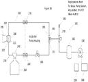
- FIG. 2 The block diagram of Figure 2 is an embodiment of the present breast pump system.
- the on-board user interface 126 which is connected to the microprocessor 128 and a Bluetooth LE radio.
- the microprocessor Also connected to the microprocessor is the battery 130 power supply, the sensors 132 and the pump and solenoid valve control 134.
- an embodiment of the breast pump system 100 has a vacuum pump 150 attached to a power source 300 and a microprocessor 290. Fluidly attached to the suction of the pump 150 is a vacuum cylinder 160. Fluidly attached to the vacuum cylinder is a vent valve 170.
- the vent valve is a solenoid valve.
- the vent valve can be a 3-way vent valve 170, as in Fig. 3B , or a 2-way vent valve 185 with a check valve 175, as in Fig. 3A .
- Also attached to the 3-way vent solenoid 170 is a vent 180 with an optional silencer and a manifold 190.
- the manifold is a 3-way connector having three attachment ports, wherein one of the attachment ports is fluidly attached to the 3-way vent solenoid 170.
- Fluidly attached to the second of the attachment ports is suction tubing 200 having a first end 201 and a second end 202.
- the first end 201 is attached to the manifold, which is fluidly attached to the pump.
- the second end 202 is fluidly attached to the suction and milk separator device 210.
- Fluidly attached to a third of the three attachments is milk tubing 230, where the milk tubing has a first end 231 and a second end 232.
- the first end 231 is fluidly attached to the manifold 190 at the third attachment port.
- the suction and milk separator device 210 Fluidly attached to the second end 232 is the suction and milk separator device 210.
- the suction and milk separator device 210 has three ports.
- the second ends 202 and 232 are attached to two ports, and the breast shield 220 is attached to the third.
- the separator device has a check valve function to block flow of the suction to the milk tubing 230.
- this check valve is a diaphragm 211.
- Between the first and second ends 231 and 232 is the milk bottle 250 with an optional lid 240.
- an isolation valve 260 Positioned between the milk bottle and the manifold 190 is an isolation valve 260, which maintains vacuum in the milk bottle.
- the isolation valve is a solenoid valve.
- the breast shield 220 Fluidly attached to suction tubing 200 and milk tubing 230 is the breast shield 220, which is attached to the suction and milk separator device 210.
- the breast shield is molded out of flexible, soft material so that as suction is applied, the shield can comfortably conform to the shape of the breast.
- the suction tubing 200 and the milk tubing 230 can have connectors 270 and 280, respectively.
- the remainder of the device 100 that is disconnected is enclosed in a pump housing (not shown) for convenience.
- a second breast shield (not shown) can be fluidly attached to the milk tubing and the suction tubing, so that both breasts can be pumped at the same time.
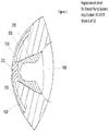
- Figure 4 shows an embodiment of a nursing bra 400 that has removable cups 410, as well as milk tubing 230 and suction tubing 200.
- Figure 5 shows a side cutaway view of the breast shield 220 and the bra cups 410 applied to a breast 500 and nipples 510.
- the suction and milk separator device 210 is connected to the milk tubing 230 and the suction tubing 200.
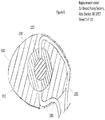
- Figure 6 shows a rear cutaway of the assembled bra cup 410, the removable breast pad 411, the breast shield 220 and the suction and milk separator device 210 with the milk tubing 230 and the suction tubing 200 attached.
- the 3-way vent solenoid 170 is closed to the vent 180, and is open and connects fluidly to the manifold 190 and to the vacuum pump 150, and suction is applied to the suction tubing 200.
- the isolation solenoid is closed, blocking any suction to milk bottle 250 via the manifold 190.
- the pump 150 is pumping and applies suction to the breast shield 220 via the suction tubing 200 and the suction and milk separator device 210.
- the low pressure (applied suction) holds the suction and milk separator diaphragm (which acts as a check valve) closed, blocking suction to the milk tubing 230.
- the 3-way vent solenoid 170 switches to open the vent 180 to the manifold 190 and closes the connection to the vacuum pump 150.
- isolation solenoid 260 opens allowing suction to be applied to the milk bottle 250 and the milk tubing 230.
- the suction tubing 200 is at lower pressure than the milk tubing, so pressure in milk tubing 230 and milk bottle 250 drops. This step is extremely brief ( ⁇ 0.2 second), such that milk bottle 250 pressure drops but does not have long enough to come to equilibrium with atmosphere via vent 180.
- the pump 150 is blocked in, but continues to run, accumulating vacuum in vacuum cylinder 160, which is positioned between the manifold and vacuum pump.
- the isolation solenoid 260 closes. Low pressure remains in milk bottle. Vacuum from suction tubing 200 continues to vent via vent 180 and the vent solenoid 170 until the pressure rises to equilibrium with atmospheric pressure. When this occurs, the diaphragm within the suction and milk separator device 210 is no longer held closed due to low pressure in the suction tubing 200, and opens due to lower pressure in the milk bottle 250. Expressed milk is pulled through the breast shield 220 and the milk tubing 230 to the milk bottle 250. The pump 150 continues to run, accumulating vacuum in vacuum cylinder 160.
- the Pumping, Semi Venting and Final Venting steps are repeated.
- the cycle time is typically less than 5 seconds. In a preferred embodiment, the cycle time is from about 1 to 4 seconds. In a more preferred embodiment, the cycle time is from about 0.5 to 2.0 seconds.
- accumulated low pressure from the vacuum cylinder 160 is applied to suction tubing 200 rapidly upon switch of vent solenoid 170 to connect the manifold 190 to vacuum cylinder 160 and the pump 150. This vacuum boost functionality adds efficiency to system, as it decreases how much air must be pumped by the Vacuum Pump.
- the suction and milk separator device 210 is located in immediate proximity to the breast shield 220.
- the suction and milk separator device exists to enforce the separation between the milk that flows into the milk tubing and the air flow from the suction tubing. It has three ports.
- the breast shield attaches to the larger port at the front.
- the suction tubing 200 attaches to a port on top, and the milk tubing 230 attaches to a port centered on the bottom. Suction pulls the milk down to be collected at the bottom of the separator device 210 where it flows through the milk tubing 230 to the milk bottle 250.
- a check valve or a diaphragm 211 may be in place within the separator device in order to ensure that no milk reaches the suction port on the top of the separator device 210.
- the breast shield interfaces sealingly with the nipple to transfer suction to the nipple and to direct the flow of expressed milk away from the breast to the suction and milk separator device.
- the breast shield of the present breast pump system is designed to simulate the feel and action of a baby's mouth.
- the shield is made of a soft silicone rubber or plastic polymer and is designed to stimulate the nipple in a manner similar to a baby's mouth and tongue.
- the use of a vacuum cylinder allows the use of a smaller, quieter pump than would otherwise be required.
- the pressure vessel acts as a vacuum storage reservoir.
- the vent solenoid opens to the manifold and the pump, and closes the vent, and provides vacuum for the system.
- the vent solenoid closes to the pump and the opens to the vent and the manifold, the system is vented, except for the pressure vessel, which is being further vacuumed by the continuously running pump.
- the vent solenoid is closed to the vent and open to the manifold and pump, the lower pressure in the pressure vessel provides a vacuum boost to the system, even with a smaller, quieter pump, and the pump runs continuously rather than switching on and off.
- the present breast pump system can be controlled wirelessly by an app on a user's smart phone or other digital device or by a front-panel display and controls.
- the remote app gives users the option of having very detailed control of the settings (pumping curves, detailed cycle timings, etc.), or allows simple single-slider-based control of the settings.
- the pump system captures the detail of the volume of milk produced in a given pumping session. This data is uploaded from the app to an internet cloud service for storage, analysis and retrieval to display.
- the app also may track pumping duration, breastfeeding frequency and diaper changes, so multiple apps or devices are not needed.
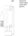
- a milk level sensor 320 can be used to determine the volume of milk pumped.
- the sensor 320 is positioned inside the pump housing 310, running the height of the milk bottle. The bottle is secured so that the air gap between the bottle and the sensor is minimized.
- the sensor electrodes are parallel to and facing the bottle.
- there is one senor per bottle and one bottle per breast so as to be able to track milk expression independent per breast.
- the microprocessor 290 is able to calculate the volume of milk expressed.
- the sensor 320 can be paired with a load cell to measure the weight of the milk expressed in order to calculate the density of the milk, yielding information about the solids content of the milk.
- the pump system 100 can have custom settings entered by the user. Optional presets are provided that may be helpful to the new user. This provides new moms with a better starting point, rather than just being given a pump and told to start pumping with no other guidance.
- the pump is much quieter than those currently used, because a much smaller pump can be used.
- a brushless motor rather than using a traditional diaphragm pump, is used.
- a linear pump motor that is inherently quieter is used.
- a vacuum cylinder to boost the suction is used with a pump, allowing the pump to run continually, thereby allowing a smaller (and therefore quieter) motor to be used on the pump, rather than the pump being turned on and off.
- the present breast pump system has the collection bottle and the pump fluidly and remotely connected to the breast shield by lengths of tubing.
- clothing and undergarments cover and engage with the shield and tubing. This provides a discreet system that can be worn under a woman's shirt.
- this improved product offers discretion in that women will not have to remove their shirts when breast pumping.
- the clothing that holds the breast shields are engaged with the nipple.
- the clothing is a three-in-one convertible undergarment. It serves the following purposes: (1) It contains the breast shield detailed below in the "comfortable" section, as well as the tubes noted above; (2) It has detachable cups similar to current nursing bras; and (3) It has built-in breast pads for when pumping is complete to prevent leaking milk from showing. These breast pads also serve as the lining of the bra.
- Tube pathways are sewn into the bra cups. These tubes are removable for easy cleaning. The tubes dangle down the torso of the user. As noted above, one set of tubes will connect to the milk collection bottle, and the other set will connect to the vacuum pump. From the side, the bra consists of multiple pieces that are hidden in the cup of the bra. Those pieces include, outer cup 410, suction and milk separator device 210, breast shield 220, and removable breast pad 411.
Claims (8)
- Brustpumpensystem (100), umfassend eine Saugleitung (200), eine Milchleitung (230), eine Pumpe (150), ein Entlüftungsventil (170), eine Milchflasche (250), einen Brustschild (220) und eine Saug- und Milchabscheidevorrichtung (210);
wobei die Saugleitung (200) ein erstes und ein zweites Ende und die Milchleitung (230) ein erstes und ein zweites Ende aufweist;
wobei das erste Ende der Saugleitung (200) in Fluidverbindung mit der Pumpe (150) steht und das zweite Ende der Saugleitung (200) in Fluidverbindung mit dem Brustschild (220) steht, um einen ersten Fluidströmungsweg zwischen der Pumpe (150) und dem Brustschild (220) zu bilden;
wobei das erste Ende der Milchleitung (230) in Fluidverbindung mit der Pumpe (150) steht und das zweite Ende der Milchleitung (230) in Fluidverbindung mit dem Brustschild (220) steht, um einen zweiten Fluidströmungsweg zwischen der Pumpe (150) und dem Brustschild (220) zu bilden;
wobei der zweite Fluidströmungsweg von dem ersten Fluidströmungsweg getrennt ist und einen alternativen Weg für das zwischen der Pumpe (150) und dem Brustschild (220) strömende Fluid darstellt;
wobei das Entlüftungsventil (170) in dem ersten Fluidströmungsweg positioniert ist;
wobei die Milchflasche (250) in dem zweiten Fluidströmungsweg positioniert ist; und
wobei die Saug- und Milchabscheidevorrichtung (210) in Fluidverbindung zwischen dem zweiten Ende der Saugleitung (200) und dem Brustschild (220) und zwischen dem zweiten Ende der Milchleitung (230) und dem Brustschild (220) steht; und die Saug- und Milchabscheidevorrichtung (210) ein Rückschlagventil (211) an dem zweiten Ende der Milchleitung (230) umfasst. - Brustpumpensystem (100) nach Anspruch 1, wobei ein Absperrventil (260) an der Milchleitung (230) zwischen der Milchflasche (250) und der Pumpe (150) verbunden ist.
- Brustpumpensystem (100) nach Anspruch 1 oder Anspruch 2, wobei das Rückschlagventil (211) eine Membran ist, die als ein Rückschlagventil wirkt.
- Brustpumpensystem (100) nach einem der vorstehenden Ansprüche, wobei ein Vakuumzylinder (160) zwischen dem Entlüftungsventil (170) und der Vakuumpumpe (150) positioniert ist.
- Brustpumpensystem (100) nach einem der vorstehenden Ansprüche, wobei mit der Pumpe (150) eine Stromquelle (300) und ein Mikroprozessor (290) verbunden sind.
- Brustpumpensystem (100) nach Anspruch 5, wobei Sensoren (320) in der Nähe der Milchflasche (250) positioniert sind, um den Füllstand der Milch in der Flasche (250) zu erfassen;
wobei die Sensoren (250) mit dem Mikroprozessor (290) verbunden sind, der die Daten speichert. - Brustpumpensystem (100) zum Ausdrücken von Muttermilch, wobei das Brustpumpensystem eine Saugleitung (200), eine Milchleitung (230), eine Pumpe (150), ein Dreiwege-Entlüftungsventil (170), eine Saug- und Milchabscheidevorrichtung (210), eine Milchflasche (250), ein Absperrventil (160) und einen Brustschild (220) umfasst; wobei die Saugleitung (200) ein erstes (201) und ein zweites Ende (202) und die Milchleitung ein erstes (231) und ein zweites Ende (232) aufweist;
wobei das erste Ende (201) der Saugleitung und das erste Ende (231) der Milchleitung in Fluidverbindung mit dem Dreiwege-Entlüftungsventil (170) und über das Dreiwege-Entlüftungsventil mit der Pumpe (150) steht; wobei das zweite Ende (232) der Saugleitung und das zweite Ende (202) der Milchleitung in Fluidverbindung mit der Saug- und Milchabscheidevorrichtung (210) steht;
wobei die Saugleitung (200) einen ersten Fluidströmungsweg zwischen der Pumpe (150) und der Milchabscheidevorrichtung (210) bildet und die Milchleitung (230) einen zweiten Fluidströmungsweg zwischen der Pumpe (150) und der Milchabscheidevorrichtung (210) bildet, wobei der zweite Fluidströmungsweg von dem ersten Fluidströmungsweg getrennt ist und einen alternativen Weg für das zwischen der Pumpe (150) und der Milchabscheidevorrichtung (210) strömende Fluid darstellt;
wobei der Brustschild (220) in Fluidverbindung mit der Saug- und Milchabscheidevorrichtung (210), der Saugleitung (200) und der Milchleitung (230) steht; wobei die Saug- und Milchabscheidevorrichtung (210) ein Rückschlagventil aufweist, das an der Verbindung zu der Milchleitung (230) positioniert ist; wobei das Rückschlagventil eine offene und eine geschlossene Position aufweist und das Rückschlagventil in der geschlossenen Position ist, wenn der Sog an der Saug- und Milchabscheidevorrichtung größer ist als der Sog an der Milchleitung;
wobei das Dreiwege-Entlüftungsventil in Fluidverbindung zwischen der Pumpe und der Ansaug- und Milchabscheidevorrichtung steht und positioniert ist; wobei das Dreiwege-Entlüftungsventil in Fluidverbindung mit einer Entlüftung steht; wobei die Milchflasche in Fluidverbindung mit der Milchleitung zwischen der Ansaug- und der Milchabscheidevorrichtung und dem Absperrventil steht; und wobei das Absperrventil in Fluidverbindung mit der Milchleitung zwischen der Milchflasche und der Pumpe steht. - Brustpumpensystem nach Anspruch 7, wobei ein Vakuumzylinder zwischen der Dreiwege-Entlüftung und der Vakuumpumpe positioniert ist.
Priority Applications (1)
| Application Number | Priority Date | Filing Date | Title |
|---|---|---|---|
| EP21173095.7A EP3884967A1 (de) | 2015-05-07 | 2016-05-09 | Verfahren zur benutzung eines milchpumpensystems |
Applications Claiming Priority (2)
| Application Number | Priority Date | Filing Date | Title |
|---|---|---|---|
| US201562158303P | 2015-05-07 | 2015-05-07 | |
| PCT/US2016/031439 WO2016179580A1 (en) | 2015-05-07 | 2016-05-09 | Breast pump system |
Related Child Applications (1)
| Application Number | Title | Priority Date | Filing Date |
|---|---|---|---|
| EP21173095.7A Division EP3884967A1 (de) | 2015-05-07 | 2016-05-09 | Verfahren zur benutzung eines milchpumpensystems |
Publications (3)
| Publication Number | Publication Date |
|---|---|
| EP3291853A1 EP3291853A1 (de) | 2018-03-14 |
| EP3291853A4 EP3291853A4 (de) | 2018-12-26 |
| EP3291853B1 true EP3291853B1 (de) | 2021-06-09 |
Family
ID=57218418
Family Applications (2)
| Application Number | Title | Priority Date | Filing Date |
|---|---|---|---|
| EP21173095.7A Pending EP3884967A1 (de) | 2015-05-07 | 2016-05-09 | Verfahren zur benutzung eines milchpumpensystems |
| EP16790223.8A Active EP3291853B1 (de) | 2015-05-07 | 2016-05-09 | Milchpumpensystem |
Family Applications Before (1)
| Application Number | Title | Priority Date | Filing Date |
|---|---|---|---|
| EP21173095.7A Pending EP3884967A1 (de) | 2015-05-07 | 2016-05-09 | Verfahren zur benutzung eines milchpumpensystems |
Country Status (14)
| Country | Link |
|---|---|
| US (2) | US10363347B2 (de) |
| EP (2) | EP3884967A1 (de) |
| JP (1) | JP6584645B2 (de) |
| CN (1) | CN107614028B (de) |
| AU (1) | AU2016258207B2 (de) |
| CA (1) | CA2984913C (de) |
| DK (1) | DK3291853T3 (de) |
| ES (1) | ES2886139T3 (de) |
| HK (1) | HK1244246A1 (de) |
| IL (1) | IL255493B (de) |
| MX (1) | MX2017014321A (de) |
| MY (1) | MY182611A (de) |
| NZ (1) | NZ737569A (de) |
| WO (1) | WO2016179580A1 (de) |
Families Citing this family (13)
| Publication number | Priority date | Publication date | Assignee | Title |
|---|---|---|---|---|
| US11717599B2 (en) | 2015-05-07 | 2023-08-08 | Babyation Inc. | Breast shield for a breast pump system |
| US10915198B2 (en) * | 2016-05-31 | 2021-02-09 | Clinicare Ltd. | Breast pump or other medical devices with dynamically adaptive pump configuration providing error detection and distinctive suction profile |
| BR112019026558A2 (pt) | 2017-06-15 | 2020-06-23 | Annabella Tech Ltd | Unidade de bomba para leite materno para uso com um sistema de bomba para leite materno para o bombeamento do leite materno do seio e sistema de bomba para leite materno |
| EP3638334B1 (de) * | 2017-06-15 | 2023-07-26 | Chiaro Technology Limited | Milchpumpensystem |
| US20190209749A1 (en) * | 2018-01-08 | 2019-07-11 | Natasha Meyers | Inside bra breast cup breast pump |
| CA3091778A1 (en) * | 2018-02-20 | 2019-08-29 | Emory University | Methods, systems and devices for expressing breastmilk |
| EP3533479A1 (de) * | 2018-02-28 | 2019-09-04 | Koninklijke Philips N.V. | Brustpumpenanordnung |
| EP3590551A1 (de) | 2018-07-04 | 2020-01-08 | Koninklijke Philips N.V. | Pumpanordnung mit konfiguration zur verwendung mit einer brustpumpenvorrichtung |
| EP3725340A1 (de) * | 2019-04-19 | 2020-10-21 | Koninklijke Philips N.V. | Kissen mit konfiguration zur befestigung an einem luftdurchlasselement einer brustpumpenvorrichtung |
| WO2021021223A1 (en) * | 2019-07-29 | 2021-02-04 | Babyation Inc. | Breast pump system |
| GB202004395D0 (en) | 2020-03-26 | 2020-05-13 | Chiaro Technology Ltd | Lima |
| AU2022223774A1 (en) * | 2021-02-20 | 2023-09-21 | Babyation Inc. | Liquid and waste collection system |
| EP4049694A1 (de) * | 2021-02-25 | 2022-08-31 | Koninklijke Philips N.V. | Speicherung und abgabe von energie in einer brustpumpenvorrichtung |
Family Cites Families (45)
| Publication number | Priority date | Publication date | Assignee | Title |
|---|---|---|---|---|
| US603564A (en) | 1898-05-03 | Breast-pump | ||
| US3822703A (en) | 1973-02-13 | 1974-07-09 | P Davisson | Breast pump |
| US4367705A (en) | 1981-04-30 | 1983-01-11 | Deere & Company | Heat activated fuel shut-off valve actuator |
| US4607596A (en) | 1983-05-11 | 1986-08-26 | Whittlestone Walter G | Milking methods and apparatus |
| US4680028A (en) * | 1984-07-02 | 1987-07-14 | Lact-Assist, Incorporated | Flexible breast receptor for breast pump |
| US4772262A (en) | 1985-04-16 | 1988-09-20 | Natural Technologies, Inc. | Portable electric breast pump |
| US4964851A (en) | 1989-03-23 | 1990-10-23 | Isg/Ag | Battery-powered breastpump |
| US5295957A (en) | 1991-12-23 | 1994-03-22 | Pigeon Co., Ltd. | Breast pump having a pressure adjusting mechanism |
| US5415632A (en) | 1994-01-10 | 1995-05-16 | Playskool, Inc. | Breast pump |
| US5476490A (en) | 1994-05-10 | 1995-12-19 | Medela, Inc. | Heating pad |
| US5542921A (en) | 1994-11-04 | 1996-08-06 | Gerber Products Company | Electric breast pump |
| US5616125A (en) | 1995-08-28 | 1997-04-01 | Jelks; Casandra N. | Apparatus for simultaneously pumping milk from the right and left breast of a nursing mother |
| US6379327B2 (en) * | 1995-10-06 | 2002-04-30 | Ellen F. Lundy | Hands-free portable breast pump system |
| DE59610174D1 (de) * | 1996-04-14 | 2003-04-03 | Medela Ag Baar | Einrichtung zum Absaugen von Muttermilch |
| US6213840B1 (en) | 1997-12-03 | 2001-04-10 | Bonnifant Heeja Han | Hands-free breast pump supporting bra and system |
| US6004288A (en) | 1998-11-24 | 1999-12-21 | Hochstedler; Judy R. | Breast pump |
| KR100371618B1 (ko) | 2000-04-19 | 2003-02-11 | 서경득 | 유축기 |
| US20030191433A1 (en) * | 2000-05-31 | 2003-10-09 | Prentiss John Gilbert | Breast pump |
| US6440100B1 (en) | 2000-05-31 | 2002-08-27 | John Gilbert Prentiss | Concealed apparatus for hands free breast milk pumping and storage |
| US6383164B1 (en) | 2000-09-26 | 2002-05-07 | Gerber Products Company | Massaging breast pump and funnel therefor |
| US20030236491A1 (en) * | 2002-06-24 | 2003-12-25 | L. Jason Clute | Apparatus for extracting milk from lactating women |
| US20040127845A1 (en) | 2002-12-27 | 2004-07-01 | Playtex Products, Inc. | Breast pump system |
| US6932790B2 (en) | 2003-07-23 | 2005-08-23 | L. Jason Clute | Adapter for human breast pumps |
| US7381197B2 (en) * | 2003-08-20 | 2008-06-03 | Kelly Patricia A | Electric breast pump |
| US20070161330A1 (en) | 2004-08-03 | 2007-07-12 | Whitehead Ernest R | Hands free breast pump bra |
| US20060270973A1 (en) | 2005-05-24 | 2006-11-30 | Chu Yun Y | Air bag nursing bra |
| JP5079364B2 (ja) | 2007-03-27 | 2012-11-21 | ピジョン株式会社 | 搾乳器 |
| US7833190B1 (en) | 2007-05-17 | 2010-11-16 | Petisamaria Hall | Breast pump |
| US8398584B2 (en) | 2009-01-16 | 2013-03-19 | Learning Curve Brands, Inc. | Breast pump and method of use |
| CA2650723C (en) | 2009-01-22 | 2015-11-24 | Wendy Corinne Bell | Breast pump support |
| WO2011035448A1 (de) | 2009-09-22 | 2011-03-31 | Medela Holding Ag | Brusthaube zum abpumpen von menschlicher muttermilch |
| US8596993B2 (en) * | 2010-01-07 | 2013-12-03 | Woodward, Inc. | Dual-pump supply system with bypass-controlled flow regulator |
| DE102010019041A1 (de) * | 2010-05-03 | 2011-11-03 | Mapa Gmbh | Elektrische Muttermilchpumpe |
| US8529501B2 (en) | 2010-06-04 | 2013-09-10 | Medela Holding Ag | One time use breastpump assembly |
| US8500679B2 (en) | 2010-06-04 | 2013-08-06 | Medela Holding Ag | Huggable breastpump |
| CH706373A1 (de) * | 2012-04-04 | 2013-10-15 | Medela Holding Ag | Saugpumpeneinheit. |
| CN102824659B (zh) * | 2012-09-20 | 2016-04-13 | 东莞市嘟宝母婴用品有限公司 | 一种吸乳器 |
| CN202892502U (zh) * | 2012-09-20 | 2013-04-24 | 东莞市嘟宝母婴用品有限公司 | 一种吸乳器 |
| US20140243766A1 (en) * | 2013-02-25 | 2014-08-28 | Valerie Kay Martuch | Vacuum assisted healing pump for post radiation and chemotherapy wounds of the breast |
| CA2902815C (en) * | 2013-03-13 | 2018-08-28 | Medela Holding Ag | System and method for managing a supply of breast milk |
| US9616156B2 (en) | 2013-03-24 | 2017-04-11 | Naya Health, Inc. | Method, apparatus, and system for expression and quantification of human breast milk |
| US20150065994A1 (en) * | 2013-08-29 | 2015-03-05 | Positive Care Ltd. | Posterior breast massage unit |
| CN103691015B (zh) * | 2014-01-04 | 2015-11-04 | 陈俊波 | 一种仿吸吮正负压吸奶器 |
| US20160003663A1 (en) | 2014-07-03 | 2016-01-07 | Texas Instruments Incorporated | Capacitive liquid level measurement with differential out-of-phase channel drive to counteract human body capacitance |
| CN204521744U (zh) * | 2015-02-15 | 2015-08-05 | 刘正爱 | 一种舒适型吸乳器 |
-
2016
- 2016-05-09 CN CN201680033112.4A patent/CN107614028B/zh active Active
- 2016-05-09 EP EP21173095.7A patent/EP3884967A1/de active Pending
- 2016-05-09 US US15/149,525 patent/US10363347B2/en active Active
- 2016-05-09 MY MYPI2017704190A patent/MY182611A/en unknown
- 2016-05-09 ES ES16790223T patent/ES2886139T3/es active Active
- 2016-05-09 WO PCT/US2016/031439 patent/WO2016179580A1/en active Application Filing
- 2016-05-09 MX MX2017014321A patent/MX2017014321A/es unknown
- 2016-05-09 DK DK16790223.8T patent/DK3291853T3/da active
- 2016-05-09 AU AU2016258207A patent/AU2016258207B2/en active Active
- 2016-05-09 EP EP16790223.8A patent/EP3291853B1/de active Active
- 2016-05-09 NZ NZ737569A patent/NZ737569A/en unknown
- 2016-05-09 JP JP2018510699A patent/JP6584645B2/ja active Active
- 2016-05-09 CA CA2984913A patent/CA2984913C/en active Active
-
2017
- 2017-11-07 IL IL255493A patent/IL255493B/en active IP Right Grant
-
2018
- 2018-03-19 HK HK18103802.2A patent/HK1244246A1/zh unknown
-
2019
- 2019-06-17 US US16/443,463 patent/US10933179B2/en active Active
Non-Patent Citations (1)
| Title |
|---|
| None * |
Also Published As
| Publication number | Publication date |
|---|---|
| JP2018517538A (ja) | 2018-07-05 |
| US10363347B2 (en) | 2019-07-30 |
| US10933179B2 (en) | 2021-03-02 |
| MY182611A (en) | 2021-01-27 |
| DK3291853T3 (da) | 2021-08-30 |
| EP3291853A4 (de) | 2018-12-26 |
| EP3884967A1 (de) | 2021-09-29 |
| WO2016179580A1 (en) | 2016-11-10 |
| EP3291853A1 (de) | 2018-03-14 |
| CN107614028B (zh) | 2021-01-15 |
| AU2016258207B2 (en) | 2020-10-15 |
| JP6584645B2 (ja) | 2019-10-02 |
| IL255493B (en) | 2021-05-31 |
| CA2984913C (en) | 2024-01-02 |
| US20160325031A1 (en) | 2016-11-10 |
| US20190328946A1 (en) | 2019-10-31 |
| IL255493A (en) | 2018-01-31 |
| NZ737569A (en) | 2018-11-30 |
| HK1244246A1 (zh) | 2018-08-03 |
| CA2984913A1 (en) | 2016-11-10 |
| AU2016258207A1 (en) | 2017-11-23 |
| ES2886139T3 (es) | 2021-12-16 |
| MX2017014321A (es) | 2019-02-26 |
| CN107614028A (zh) | 2018-01-19 |
Similar Documents
| Publication | Publication Date | Title |
|---|---|---|
| US10933179B2 (en) | Breast pump system | |
| JP2018517538A5 (de) | ||
| US10568996B2 (en) | Breast pump | |
| CA2451171C (en) | System for a portable hands-free breast pump and method of using the same | |
| US7785305B2 (en) | System for collecting breast milk from a human breast | |
| JP2013505087A (ja) | ヒトの母乳を搾り出すための乳房シールド | |
| CN108289982B (zh) | 用于双边吸乳泵的泵装置、双边吸乳泵及操作方法 | |
| US20220111128A1 (en) | Breastmilk collection system | |
| US11717599B2 (en) | Breast shield for a breast pump system | |
| WO2021021223A1 (en) | Breast pump system |
Legal Events
| Date | Code | Title | Description |
|---|---|---|---|
| STAA | Information on the status of an ep patent application or granted ep patent |
Free format text: STATUS: THE INTERNATIONAL PUBLICATION HAS BEEN MADE |
|
| PUAI | Public reference made under article 153(3) epc to a published international application that has entered the european phase |
Free format text: ORIGINAL CODE: 0009012 |
|
| STAA | Information on the status of an ep patent application or granted ep patent |
Free format text: STATUS: REQUEST FOR EXAMINATION WAS MADE |
|
| 17P | Request for examination filed |
Effective date: 20171127 |
|
| AK | Designated contracting states |
Kind code of ref document: A1 Designated state(s): AL AT BE BG CH CY CZ DE DK EE ES FI FR GB GR HR HU IE IS IT LI LT LU LV MC MK MT NL NO PL PT RO RS SE SI SK SM TR |
|
| AX | Request for extension of the european patent |
Extension state: BA ME |
|
| REG | Reference to a national code |
Ref country code: HK Ref legal event code: DE Ref document number: 1244246 Country of ref document: HK |
|
| DAV | Request for validation of the european patent (deleted) | ||
| DAX | Request for extension of the european patent (deleted) | ||
| A4 | Supplementary search report drawn up and despatched |
Effective date: 20181123 |
|
| RIC1 | Information provided on ipc code assigned before grant |
Ipc: A61M 1/06 20060101AFI20181119BHEP |
|
| STAA | Information on the status of an ep patent application or granted ep patent |
Free format text: STATUS: EXAMINATION IS IN PROGRESS |
|
| 17Q | First examination report despatched |
Effective date: 20190905 |
|
| GRAP | Despatch of communication of intention to grant a patent |
Free format text: ORIGINAL CODE: EPIDOSNIGR1 |
|
| STAA | Information on the status of an ep patent application or granted ep patent |
Free format text: STATUS: GRANT OF PATENT IS INTENDED |
|
| INTG | Intention to grant announced |
Effective date: 20201207 |
|
| GRAS | Grant fee paid |
Free format text: ORIGINAL CODE: EPIDOSNIGR3 |
|
| GRAA | (expected) grant |
Free format text: ORIGINAL CODE: 0009210 |
|
| STAA | Information on the status of an ep patent application or granted ep patent |
Free format text: STATUS: THE PATENT HAS BEEN GRANTED |
|
| AK | Designated contracting states |
Kind code of ref document: B1 Designated state(s): AL AT BE BG CH CY CZ DE DK EE ES FI FR GB GR HR HU IE IS IT LI LT LU LV MC MK MT NL NO PL PT RO RS SE SI SK SM TR |
|
| RAP1 | Party data changed (applicant data changed or rights of an application transferred) |
Owner name: BABYATION INC. |
|
| REG | Reference to a national code |
Ref country code: GB Ref legal event code: FG4D |
|
| RIN1 | Information on inventor provided before grant (corrected) |
Inventor name: RUDOLPH, SAMANTHA Inventor name: MILLER, JARED |
|
| REG | Reference to a national code |
Ref country code: AT Ref legal event code: REF Ref document number: 1399936 Country of ref document: AT Kind code of ref document: T Effective date: 20210615 Ref country code: CH Ref legal event code: EP |
|
| REG | Reference to a national code |
Ref country code: DE Ref legal event code: R096 Ref document number: 602016059172 Country of ref document: DE |
|
| REG | Reference to a national code |
Ref country code: IE Ref legal event code: FG4D |
|
| REG | Reference to a national code |
Ref country code: DK Ref legal event code: T3 Effective date: 20210827 |
|
| REG | Reference to a national code |
Ref country code: FI Ref legal event code: FGE |
|
| REG | Reference to a national code |
Ref country code: NL Ref legal event code: FP |
|
| REG | Reference to a national code |
Ref country code: SE Ref legal event code: TRGR |
|
| REG | Reference to a national code |
Ref country code: LT Ref legal event code: MG9D |
|
| PG25 | Lapsed in a contracting state [announced via postgrant information from national office to epo] |
Ref country code: BG Free format text: LAPSE BECAUSE OF FAILURE TO SUBMIT A TRANSLATION OF THE DESCRIPTION OR TO PAY THE FEE WITHIN THE PRESCRIBED TIME-LIMIT Effective date: 20210909 Ref country code: HR Free format text: LAPSE BECAUSE OF FAILURE TO SUBMIT A TRANSLATION OF THE DESCRIPTION OR TO PAY THE FEE WITHIN THE PRESCRIBED TIME-LIMIT Effective date: 20210609 Ref country code: LT Free format text: LAPSE BECAUSE OF FAILURE TO SUBMIT A TRANSLATION OF THE DESCRIPTION OR TO PAY THE FEE WITHIN THE PRESCRIBED TIME-LIMIT Effective date: 20210609 |
|
| REG | Reference to a national code |
Ref country code: NO Ref legal event code: T2 Effective date: 20210609 |
|
| REG | Reference to a national code |
Ref country code: GR Ref legal event code: EP Ref document number: 20210402408 Country of ref document: GR Effective date: 20211013 |
|
| REG | Reference to a national code |
Ref country code: AT Ref legal event code: MK05 Ref document number: 1399936 Country of ref document: AT Kind code of ref document: T Effective date: 20210609 |
|
| PG25 | Lapsed in a contracting state [announced via postgrant information from national office to epo] |
Ref country code: LV Free format text: LAPSE BECAUSE OF FAILURE TO SUBMIT A TRANSLATION OF THE DESCRIPTION OR TO PAY THE FEE WITHIN THE PRESCRIBED TIME-LIMIT Effective date: 20210609 Ref country code: RS Free format text: LAPSE BECAUSE OF FAILURE TO SUBMIT A TRANSLATION OF THE DESCRIPTION OR TO PAY THE FEE WITHIN THE PRESCRIBED TIME-LIMIT Effective date: 20210609 |
|
| REG | Reference to a national code |
Ref country code: ES Ref legal event code: FG2A Ref document number: 2886139 Country of ref document: ES Kind code of ref document: T3 Effective date: 20211216 |
|
| PG25 | Lapsed in a contracting state [announced via postgrant information from national office to epo] |
Ref country code: EE Free format text: LAPSE BECAUSE OF FAILURE TO SUBMIT A TRANSLATION OF THE DESCRIPTION OR TO PAY THE FEE WITHIN THE PRESCRIBED TIME-LIMIT Effective date: 20210609 Ref country code: CZ Free format text: LAPSE BECAUSE OF FAILURE TO SUBMIT A TRANSLATION OF THE DESCRIPTION OR TO PAY THE FEE WITHIN THE PRESCRIBED TIME-LIMIT Effective date: 20210609 Ref country code: SK Free format text: LAPSE BECAUSE OF FAILURE TO SUBMIT A TRANSLATION OF THE DESCRIPTION OR TO PAY THE FEE WITHIN THE PRESCRIBED TIME-LIMIT Effective date: 20210609 Ref country code: SM Free format text: LAPSE BECAUSE OF FAILURE TO SUBMIT A TRANSLATION OF THE DESCRIPTION OR TO PAY THE FEE WITHIN THE PRESCRIBED TIME-LIMIT Effective date: 20210609 Ref country code: RO Free format text: LAPSE BECAUSE OF FAILURE TO SUBMIT A TRANSLATION OF THE DESCRIPTION OR TO PAY THE FEE WITHIN THE PRESCRIBED TIME-LIMIT Effective date: 20210609 Ref country code: PT Free format text: LAPSE BECAUSE OF FAILURE TO SUBMIT A TRANSLATION OF THE DESCRIPTION OR TO PAY THE FEE WITHIN THE PRESCRIBED TIME-LIMIT Effective date: 20211011 Ref country code: AT Free format text: LAPSE BECAUSE OF FAILURE TO SUBMIT A TRANSLATION OF THE DESCRIPTION OR TO PAY THE FEE WITHIN THE PRESCRIBED TIME-LIMIT Effective date: 20210609 |
|
| PG25 | Lapsed in a contracting state [announced via postgrant information from national office to epo] |
Ref country code: PL Free format text: LAPSE BECAUSE OF FAILURE TO SUBMIT A TRANSLATION OF THE DESCRIPTION OR TO PAY THE FEE WITHIN THE PRESCRIBED TIME-LIMIT Effective date: 20210609 |
|
| REG | Reference to a national code |
Ref country code: DE Ref legal event code: R097 Ref document number: 602016059172 Country of ref document: DE |
|
| PLBE | No opposition filed within time limit |
Free format text: ORIGINAL CODE: 0009261 |
|
| STAA | Information on the status of an ep patent application or granted ep patent |
Free format text: STATUS: NO OPPOSITION FILED WITHIN TIME LIMIT |
|
| 26N | No opposition filed |
Effective date: 20220310 |
|
| PG25 | Lapsed in a contracting state [announced via postgrant information from national office to epo] |
Ref country code: AL Free format text: LAPSE BECAUSE OF FAILURE TO SUBMIT A TRANSLATION OF THE DESCRIPTION OR TO PAY THE FEE WITHIN THE PRESCRIBED TIME-LIMIT Effective date: 20210609 |
|
| P01 | Opt-out of the competence of the unified patent court (upc) registered |
Effective date: 20230513 |
|
| PGFP | Annual fee paid to national office [announced via postgrant information from national office to epo] |
Ref country code: LU Payment date: 20230511 Year of fee payment: 8 |
|
| PGFP | Annual fee paid to national office [announced via postgrant information from national office to epo] |
Ref country code: NO Payment date: 20230516 Year of fee payment: 8 Ref country code: NL Payment date: 20230511 Year of fee payment: 8 Ref country code: MC Payment date: 20230522 Year of fee payment: 8 Ref country code: IT Payment date: 20230524 Year of fee payment: 8 Ref country code: IE Payment date: 20230508 Year of fee payment: 8 Ref country code: FR Payment date: 20230516 Year of fee payment: 8 Ref country code: ES Payment date: 20230609 Year of fee payment: 8 Ref country code: DK Payment date: 20230515 Year of fee payment: 8 Ref country code: DE Payment date: 20230524 Year of fee payment: 8 Ref country code: CH Payment date: 20230602 Year of fee payment: 8 |
|
| PGFP | Annual fee paid to national office [announced via postgrant information from national office to epo] |
Ref country code: SE Payment date: 20230516 Year of fee payment: 8 Ref country code: IS Payment date: 20230517 Year of fee payment: 8 Ref country code: GR Payment date: 20230525 Year of fee payment: 8 Ref country code: FI Payment date: 20230512 Year of fee payment: 8 |
|
| PGFP | Annual fee paid to national office [announced via postgrant information from national office to epo] |
Ref country code: BE Payment date: 20230511 Year of fee payment: 8 |
|
| PGFP | Annual fee paid to national office [announced via postgrant information from national office to epo] |
Ref country code: GB Payment date: 20230424 Year of fee payment: 8 |
|
| PG25 | Lapsed in a contracting state [announced via postgrant information from national office to epo] |
Ref country code: HU Free format text: LAPSE BECAUSE OF FAILURE TO SUBMIT A TRANSLATION OF THE DESCRIPTION OR TO PAY THE FEE WITHIN THE PRESCRIBED TIME-LIMIT; INVALID AB INITIO Effective date: 20160509 |