EP3291504B1 - Authentication and secure transmission of data between signature devices and host computers using transport layer security - Google Patents
Authentication and secure transmission of data between signature devices and host computers using transport layer security Download PDFInfo
- Publication number
- EP3291504B1 EP3291504B1 EP17187244.3A EP17187244A EP3291504B1 EP 3291504 B1 EP3291504 B1 EP 3291504B1 EP 17187244 A EP17187244 A EP 17187244A EP 3291504 B1 EP3291504 B1 EP 3291504B1
- Authority
- EP
- European Patent Office
- Prior art keywords
- certificate
- signature
- host computer
- signature device
- public key
- Prior art date
- Legal status (The legal status is an assumption and is not a legal conclusion. Google has not performed a legal analysis and makes no representation as to the accuracy of the status listed.)
- Active
Links
- 230000005540 biological transmission Effects 0.000 title description 5
- 238000000034 method Methods 0.000 claims description 39
- 230000006854 communication Effects 0.000 claims description 23
- 238000004891 communication Methods 0.000 claims description 23
- 230000004044 response Effects 0.000 claims description 15
- 238000012546 transfer Methods 0.000 claims description 15
- 230000002093 peripheral effect Effects 0.000 claims description 12
- 230000008569 process Effects 0.000 description 21
- 238000010586 diagram Methods 0.000 description 20
- 238000012545 processing Methods 0.000 description 10
- 230000007246 mechanism Effects 0.000 description 8
- 238000005516 engineering process Methods 0.000 description 7
- 238000013507 mapping Methods 0.000 description 6
- 230000008901 benefit Effects 0.000 description 3
- 208000032960 Tablet physical issue Diseases 0.000 description 2
- 238000013461 design Methods 0.000 description 2
- 238000009434 installation Methods 0.000 description 2
- 238000012986 modification Methods 0.000 description 2
- 230000004048 modification Effects 0.000 description 2
- 230000008520 organization Effects 0.000 description 2
- 238000012795 verification Methods 0.000 description 2
- 238000013459 approach Methods 0.000 description 1
- 230000007175 bidirectional communication Effects 0.000 description 1
- 230000007123 defense Effects 0.000 description 1
- 230000006870 function Effects 0.000 description 1
- 230000002085 persistent effect Effects 0.000 description 1
- 238000002360 preparation method Methods 0.000 description 1
- 238000005070 sampling Methods 0.000 description 1
- 239000007787 solid Substances 0.000 description 1
Images


Classifications
-
- H—ELECTRICITY
- H04—ELECTRIC COMMUNICATION TECHNIQUE
- H04L—TRANSMISSION OF DIGITAL INFORMATION, e.g. TELEGRAPHIC COMMUNICATION
- H04L63/00—Network architectures or network communication protocols for network security
- H04L63/16—Implementing security features at a particular protocol layer
- H04L63/166—Implementing security features at a particular protocol layer at the transport layer
-
- G—PHYSICS
- G06—COMPUTING; CALCULATING OR COUNTING
- G06Q—INFORMATION AND COMMUNICATION TECHNOLOGY [ICT] SPECIALLY ADAPTED FOR ADMINISTRATIVE, COMMERCIAL, FINANCIAL, MANAGERIAL OR SUPERVISORY PURPOSES; SYSTEMS OR METHODS SPECIALLY ADAPTED FOR ADMINISTRATIVE, COMMERCIAL, FINANCIAL, MANAGERIAL OR SUPERVISORY PURPOSES, NOT OTHERWISE PROVIDED FOR
- G06Q20/00—Payment architectures, schemes or protocols
- G06Q20/38—Payment protocols; Details thereof
- G06Q20/382—Payment protocols; Details thereof insuring higher security of transaction
- G06Q20/3821—Electronic credentials
- G06Q20/38215—Use of certificates or encrypted proofs of transaction rights
-
- G—PHYSICS
- G06—COMPUTING; CALCULATING OR COUNTING
- G06F—ELECTRIC DIGITAL DATA PROCESSING
- G06F21/00—Security arrangements for protecting computers, components thereof, programs or data against unauthorised activity
- G06F21/60—Protecting data
- G06F21/64—Protecting data integrity, e.g. using checksums, certificates or signatures
-
- G—PHYSICS
- G06—COMPUTING; CALCULATING OR COUNTING
- G06F—ELECTRIC DIGITAL DATA PROCESSING
- G06F21/00—Security arrangements for protecting computers, components thereof, programs or data against unauthorised activity
- G06F21/70—Protecting specific internal or peripheral components, in which the protection of a component leads to protection of the entire computer
- G06F21/82—Protecting input, output or interconnection devices
- G06F21/83—Protecting input, output or interconnection devices input devices, e.g. keyboards, mice or controllers thereof
-
- G—PHYSICS
- G07—CHECKING-DEVICES
- G07F—COIN-FREED OR LIKE APPARATUS
- G07F7/00—Mechanisms actuated by objects other than coins to free or to actuate vending, hiring, coin or paper currency dispensing or refunding apparatus
- G07F7/08—Mechanisms actuated by objects other than coins to free or to actuate vending, hiring, coin or paper currency dispensing or refunding apparatus by coded identity card or credit card or other personal identification means
- G07F7/10—Mechanisms actuated by objects other than coins to free or to actuate vending, hiring, coin or paper currency dispensing or refunding apparatus by coded identity card or credit card or other personal identification means together with a coded signal, e.g. in the form of personal identification information, like personal identification number [PIN] or biometric data
- G07F7/1016—Devices or methods for securing the PIN and other transaction-data, e.g. by encryption
-
- G—PHYSICS
- G07—CHECKING-DEVICES
- G07F—COIN-FREED OR LIKE APPARATUS
- G07F7/00—Mechanisms actuated by objects other than coins to free or to actuate vending, hiring, coin or paper currency dispensing or refunding apparatus
- G07F7/08—Mechanisms actuated by objects other than coins to free or to actuate vending, hiring, coin or paper currency dispensing or refunding apparatus by coded identity card or credit card or other personal identification means
- G07F7/10—Mechanisms actuated by objects other than coins to free or to actuate vending, hiring, coin or paper currency dispensing or refunding apparatus by coded identity card or credit card or other personal identification means together with a coded signal, e.g. in the form of personal identification information, like personal identification number [PIN] or biometric data
- G07F7/1025—Identification of user by a PIN code
- G07F7/1033—Details of the PIN pad
- G07F7/1041—PIN input keyboard gets new key allocation at each use
-
- H—ELECTRICITY
- H04—ELECTRIC COMMUNICATION TECHNIQUE
- H04L—TRANSMISSION OF DIGITAL INFORMATION, e.g. TELEGRAPHIC COMMUNICATION
- H04L63/00—Network architectures or network communication protocols for network security
- H04L63/06—Network architectures or network communication protocols for network security for supporting key management in a packet data network
- H04L63/061—Network architectures or network communication protocols for network security for supporting key management in a packet data network for key exchange, e.g. in peer-to-peer networks
-
- H—ELECTRICITY
- H04—ELECTRIC COMMUNICATION TECHNIQUE
- H04L—TRANSMISSION OF DIGITAL INFORMATION, e.g. TELEGRAPHIC COMMUNICATION
- H04L63/00—Network architectures or network communication protocols for network security
- H04L63/08—Network architectures or network communication protocols for network security for authentication of entities
- H04L63/0823—Network architectures or network communication protocols for network security for authentication of entities using certificates
-
- H—ELECTRICITY
- H04—ELECTRIC COMMUNICATION TECHNIQUE
- H04L—TRANSMISSION OF DIGITAL INFORMATION, e.g. TELEGRAPHIC COMMUNICATION
- H04L63/00—Network architectures or network communication protocols for network security
- H04L63/20—Network architectures or network communication protocols for network security for managing network security; network security policies in general
-
- H—ELECTRICITY
- H04—ELECTRIC COMMUNICATION TECHNIQUE
- H04L—TRANSMISSION OF DIGITAL INFORMATION, e.g. TELEGRAPHIC COMMUNICATION
- H04L9/00—Cryptographic mechanisms or cryptographic arrangements for secret or secure communications; Network security protocols
- H04L9/08—Key distribution or management, e.g. generation, sharing or updating, of cryptographic keys or passwords
- H04L9/0816—Key establishment, i.e. cryptographic processes or cryptographic protocols whereby a shared secret becomes available to two or more parties, for subsequent use
- H04L9/0838—Key agreement, i.e. key establishment technique in which a shared key is derived by parties as a function of information contributed by, or associated with, each of these
-
- H—ELECTRICITY
- H04—ELECTRIC COMMUNICATION TECHNIQUE
- H04L—TRANSMISSION OF DIGITAL INFORMATION, e.g. TELEGRAPHIC COMMUNICATION
- H04L9/00—Cryptographic mechanisms or cryptographic arrangements for secret or secure communications; Network security protocols
- H04L9/08—Key distribution or management, e.g. generation, sharing or updating, of cryptographic keys or passwords
- H04L9/0861—Generation of secret information including derivation or calculation of cryptographic keys or passwords
- H04L9/0866—Generation of secret information including derivation or calculation of cryptographic keys or passwords involving user or device identifiers, e.g. serial number, physical or biometrical information, DNA, hand-signature or measurable physical characteristics
-
- H—ELECTRICITY
- H04—ELECTRIC COMMUNICATION TECHNIQUE
- H04L—TRANSMISSION OF DIGITAL INFORMATION, e.g. TELEGRAPHIC COMMUNICATION
- H04L9/00—Cryptographic mechanisms or cryptographic arrangements for secret or secure communications; Network security protocols
- H04L9/32—Cryptographic mechanisms or cryptographic arrangements for secret or secure communications; Network security protocols including means for verifying the identity or authority of a user of the system or for message authentication, e.g. authorization, entity authentication, data integrity or data verification, non-repudiation, key authentication or verification of credentials
- H04L9/3247—Cryptographic mechanisms or cryptographic arrangements for secret or secure communications; Network security protocols including means for verifying the identity or authority of a user of the system or for message authentication, e.g. authorization, entity authentication, data integrity or data verification, non-repudiation, key authentication or verification of credentials involving digital signatures
-
- H—ELECTRICITY
- H04—ELECTRIC COMMUNICATION TECHNIQUE
- H04L—TRANSMISSION OF DIGITAL INFORMATION, e.g. TELEGRAPHIC COMMUNICATION
- H04L9/00—Cryptographic mechanisms or cryptographic arrangements for secret or secure communications; Network security protocols
- H04L9/32—Cryptographic mechanisms or cryptographic arrangements for secret or secure communications; Network security protocols including means for verifying the identity or authority of a user of the system or for message authentication, e.g. authorization, entity authentication, data integrity or data verification, non-repudiation, key authentication or verification of credentials
- H04L9/3263—Cryptographic mechanisms or cryptographic arrangements for secret or secure communications; Network security protocols including means for verifying the identity or authority of a user of the system or for message authentication, e.g. authorization, entity authentication, data integrity or data verification, non-repudiation, key authentication or verification of credentials involving certificates, e.g. public key certificate [PKC] or attribute certificate [AC]; Public key infrastructure [PKI] arrangements
- H04L9/3268—Cryptographic mechanisms or cryptographic arrangements for secret or secure communications; Network security protocols including means for verifying the identity or authority of a user of the system or for message authentication, e.g. authorization, entity authentication, data integrity or data verification, non-repudiation, key authentication or verification of credentials involving certificates, e.g. public key certificate [PKC] or attribute certificate [AC]; Public key infrastructure [PKI] arrangements using certificate validation, registration, distribution or revocation, e.g. certificate revocation list [CRL]
-
- H—ELECTRICITY
- H04—ELECTRIC COMMUNICATION TECHNIQUE
- H04W—WIRELESS COMMUNICATION NETWORKS
- H04W12/00—Security arrangements; Authentication; Protecting privacy or anonymity
- H04W12/06—Authentication
- H04W12/069—Authentication using certificates or pre-shared keys
-
- G—PHYSICS
- G06—COMPUTING; CALCULATING OR COUNTING
- G06F—ELECTRIC DIGITAL DATA PROCESSING
- G06F21/00—Security arrangements for protecting computers, components thereof, programs or data against unauthorised activity
- G06F21/70—Protecting specific internal or peripheral components, in which the protection of a component leads to protection of the entire computer
- G06F21/82—Protecting input, output or interconnection devices
Definitions
- Electronic handwriting is increasingly important in a variety of contexts. For example, electronic handwriting is now commonly used in place of pen and paper to obtain a credit card holder's affirmation of a credit card transaction.
- signature pads and tablets are used in banks, retail stores, and other locations to obtain signatures on legally binding documents. Given the sensitive nature of such applications, authentication of signature devices and security of data being transferred between signature devices and other computers has become a critical issue for suppliers and users of such devices. Proprietary security and encryption schemes are possible, but they require significant effort and expense, as well as a high level of trust between designers of such schemes and their customers.
- U.S. Patent No. 8,700,905 discloses, for example, a signature capture apparatus that captures a handwritten signature and encrypts the signature data.
- U.S. Patent No. 7,933,840 discloses, for example, a signature device which encrypts signature data with transaction data provided by a host computer.
- CN 103 888 422 A discloses a method comprising steps: after a client establishes a connection with a server, the client receives a certificate updating notification sent by the server when a certificate needs updating; after receiving the certificate updating notification, the client sends identity identification information to the server; the client receives a certificate updating command which is sent when the server determines the client is qualified for carrying out certificate updating, and generates a certificate signature request comprising a security certificate preparation file after receiving the certificate updating command; the client sends the certificate signature request to the server; and the client receives the security certificate file sent by the server.
- CN 204 442 397 U discloses an electronic signature encryption device comprising a handwriting pen and an electronic signature encryption screen.
- the electronic signature encryption screen comprises an interface module for connecting with an external computer so as to enable USB signals output by the computer to be accessed, a control panel connected with the interface module and used for converting the USB signals into LVDS signals, a touch screen connected with the control panel and used for displaying the LVDS signals and receiving handwriting information input by the handwriting pen under a screen display interface, and an encryption module connected with the touch screen and used for encrypting the handwriting information and converting the encrypted handwriting information into the USB signals, wherein the output end of the encryption module is connected with the interface module.
- US 2015/154414 A1 discloses a computer-implemented authentication method comprising the step of enabling a user to input an identifier into an electronic device having a screen and a keypad operable within a keypad zone of the screen; by operating at least one key of the keypad via an image of at least part of a scrambled keypad which is displayed at least partially within the keypad zone.
- US 2006/037067 A1 discloses a system in which, in an exchange of data between a client terminal and a secure database server, the data is encoded using positional information generated by a combination generator in a separate security server.
- a connection is established between a signature device and a host computer via an interface (e.g., a universal serial bus (USB) interface), and a transport layer security (TLS) connection is established between the signature device and the host computer via the interface.
- the host computer sends a command via the interface to the signature device to generate a new key pair, receives a certificate signing request (CSR) from the signature device via the interface, sends the CSR to a user certificate authority (CA), receives a public key certificate from the user CA, and sends the public key certificate to the signature device via the interface.
- CSR certificate signing request
- CA user certificate authority
- the invention in another aspect, relates to a computer-implemented method, wherein a connection is established between a signature device and a host computer via a USB interface, and a TLS connection is established between the signature device and the host computer via the USB interface.
- the signature device acts as a TLS server
- the host computer acts as a TLS client.
- data is received from or transmitted to the signature device via a USB bulk transfer.
- a TLS connection is established (e.g., via a USB interface) between a signature device and a host computer running an application.
- the host computer selects an image file from a set of image files (e.g., representing different layouts of characters for entering a PIN) stored in the host computer, wherein each image file in the set of image files has a different mapping between image regions and a character alphabet,
- the host computer encrypts the selected image, sends the selected image to the signature device over the TLS connection, receives encrypted pen data (e.g., representing user selection of characters in a PIN) from the signature device over the TLS connection, decrypts the encrypted pen data, and identifies at least one character based on the decrypted pen data and the mapping between image regions and the character alphabet associated with the selected image file.
- encrypted pen data e.g., representing user selection of characters in a PIN
- the signature device receives an encrypted image selected from a set of images stored in the host computer over the TLS connection, decrypts the encrypted image, and sends encrypted pen data to the host computer over the TLS connection.
- Each image in the set of images has a different mapping between image regions and a character alphabet, and the encrypted pen data represents user selection of characters in a PIN.
- a signature tablet for use with an external computer comprises a sensor section configured to obtain a series of pen data and a controller configured to generate a public key and a private key, obtain a third party certificate for the public key, establish a secure connection with the external computer by using the public key signed by the third party, and send the series of pen data over the secure connection as the series of pen data is obtained.
- data such as pen data, control data, or image data may be received or transmitted via a USB bulk transfer mechanism.
- a signature tablet communicates with an external computer.
- the signature tablet comprises an input sensor (e.g., an electromagnetic resonance (EMR) sensor), an input sensor controller (e.g., an EMR controller), and a main controller.
- the main controller comprises a peripheral device interface (e.g., a USB interface) and memory.
- the signature tablet also may include a display (e.g., an LCD display).
- the input sensor controller is configured to detect a series of positions of a pen and generate a series of pen data.
- the memory stores a key pair of a public key and a private key, a server certificate for the public key, and firmware.
- the firmware is configured to cause the main controller to establish a connection with the external computer over the peripheral device interface when the peripheral device interface is detected to be connected with the external computer, provide the server certificate including the public key to the external computer over the connection, and, in case a response indicating the server certificate is trusted by the external computer is received, send the series of pen data to the external computer.
- the external computer may be programmed to receive the server certificate including the public key over the connection, determine whether the server certificate is trusted or not, send the response indicating the server certificate is trusted to the signature tablet in a case where the server certificate is trusted, and receive the series of pen data.
- the firmware may be further configured to cause the main controller to receive an encrypted shared secret key generated by the external computer over the connection (e.g., via a secure TLS or SSL (Secure Sockets Layer) session established directly via the connection over the USB peripheral device interface) as the response indicating the server certificate is trusted by the external computer; and send the series of pen data by encrypting the series of pen data with the shared secret key.
- the firmware may be further configured to cause the main controller to establish a default pipe for exchanging USB device properties and two pipes for USB bulk transfer for two-way communication with the external computer over the peripheral device interface. The series of pen data may be sent over the TLS session established via the two pipes for USB bulk transfer.
- the signature tablet may issue a CSR.
- the firmware may be further configured to cause the main controller to generate a first key pair in response to a command, send a CSR for the public key in order to obtain the server certificate signed by a CA, and store the server certificate including the public key in the memory.
- the firmware may be further configured to cause the main controller to generate a new key pair of a new public key and a new private key in response to another command, send a CSR for the new public key in order to obtain the public key signed by a second CA, and update the memory to store the new key pair and a server certificate for the new public key signed by the second CA.
- the firmware may be further configured to cause the main controller to retrieve a client certificate including a public key of the external computer from the external computer, determine whether the client certificate is trusted or not, and, in case the client certificate is trusted and the response indicating that the server certificate is trusted by the external computer is received, send the series of pen data to the external computer.
- the firmware may be further configured to cause the signature tablet to decrypt encrypted image data sent from the external computer over the connection to obtain image data, and display a path of the positions of the pen in a manner such that the path is overlaid with the image data when displayed on the display.
- the image data may represent either a first image for entering a handwriting signature or a second image showing a layout of characters for entering a PIN.
- the firmware may be further configured to cause the signature tablet to display the path of the positions of the pen in a manner such that the path is overlaid with the first image, and display a character selected by the positions in a highlighted manner.
- U.S. Patent No. 8,700,905 discloses, for example, a signature capture apparatus that captures a handwritten signature and encrypts the signature data
- U.S. Patent No. 7,933,840 discloses, for example, a signature device which encrypts signature data with transaction data provided by a host computer.
- no practical solutions have been provided for a mechanism for authentication, either one (one-way or both way) mechanism between signature tablet and host computer.
- Using a pre-shared key or temporary shared transaction data as an encryption key is not enough to protect against man-in-the-middle attacks, or to account for situations in which a signature tablet has been replaced by third party before the tablet has been newly installed (e.g., in a bank or user site) after the signature tablet had shipped.
- data can be transmitted via USB from a signature device to a host PC using different USB transfer mechanisms, to protect the transmission it has previously been necessary to use a complex approach of providing different encryption schemes for encrypting and transmitting various types of data (e.g., configuration or control data, pen data, image data, or other data) between the signature device and the host PC using various USB transfer mechanisms (e.g., control transfers, interrupt transfers).
- various USB transfer mechanisms e.g., control transfers, interrupt transfers.
- TLS Transport Layer Security
- SSL Secure Sockets Layer
- TLS is often used in web browsers and web servers to protect TCP/IP links as secure HTTPS connections.
- TLS may be implemented using open-source libraries and toolkits, such as OpenSSL, provided by the OpenSSL Software Foundation, or wolfSSL (formerly CyaSSL), provided by wolfSSL Inc.
- OpenSSL OpenSSL
- wolfSSL formerly CyaSSL
- TLS 1.2 A current version of the TLS standard, TLS 1.2, is defined in RFC 5246, which is a document available from the Internet Engineering Task Force (IETF).
- TLS uses public key cryptography, which requires assurance that the party encrypting the message is using the encryption algorithm of the correct party, Otherwise, the message may be vulnerable to man-in-the-middle attacks in which an unauthorized party impersonates the actual parties to the transaction, allowing the unauthorized party to view an unencrypted message.
- PKI public key infrastructure
- the CA provides a public key certificate for the message.
- the public key certificate includes the CA's digital signature along with a party's public key and a text string identifier of the party.
- the public key certificate assures the encrypting party that the public key belongs to the intended recipient.
- a TLS protocol is used for authentication and to protect links between signature devices and the computers they communicate with.
- TLS for these purposes has several advantages. For example, data can be protected in both directions between the signature device the computer it is communicating with.
- TLS is an industry standard that is well supported and understood, and it may be implemented using open-source libraries and toolkits, such as OpenSSL or wolfSSL.
- TLS Universal Serial Bus
- Described embodiments also allow mutual authentication between signature devices and other computers over USB channels.
- Described embodiments can be used to provide mutual authentication of signature devices and the computers they communicate with, and as a defense against security breaches such as attempted connection of unauthorized computers to signature devices, and malicious hijacking of USB connections.
- a signature device can provide security with public key certificates signed by a private key held by the manufacturer of the signature device, and a public verification key, which may be distributed with host computer software.
- the manufacturer is the CA for original certificates on the signature device.
- a user certificate and private key pair is provided as an enhancement to the default level.
- the default-level key pair provided by the manufacturer may be replaced by a second-level key pair that is generated in the signature device.
- private key parts of the key pairs may be generated and stored in the signature device, which can help to ensure that the key pairs are properly generated and remain secure.
- a device designated as a client typically authenticates a device designated as a server.
- a signature device acts as a TLS server and a host computer acts as a TLS client. If authentication of the signature device is desired, the host computer may accept a certificate from the signature device only if it has been signed by a CA. Similarly, if authentication of the host computer by the signature device is desired, the signature device may accept a certificate from a host computer only if it has been signed by a CA. Mutual authentication may include both of these forms of authentication.
- Client-side certificates also can be provided.
- a command e.g., a command to generate a key pair
- the signature device can store the root certificate in a certification key chain, which can be used as a verification key to check authenticity of TLS clients that may connect to the signature device.
- a certificate revocation list can be used to specify certificates that are no longer authorized. This can provide protection against unauthorized computers connecting to the signature device.
- signature device refers to a device that captures handwriting input for signatures.
- Signature devices may be implemented as dedicated signature collection devices, such as signature pad devices, or as general purpose devices, such as suitably configured smart phones or tablet computers.
- Signature devices are not necessarily strictly input devices, and may include other functionality (e.g., display functionality, data transmission functionality, etc.). Further details on illustrative signature devices are provided below.
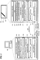
- FIGURE 1 is a block diagram of an illustrative system in which described embodiments may be implemented.
- signature device 100 communicates with a host computer 200 via a bi-directional, TLS-protected USB channel.
- the host computer 200 includes a signature application 205, a signature control instance 210 and related libraries (e.g., signature SDK libraries), and a TLS communication handler 220 that allows the host computer to communicate with the signature device 100 over a TLS channel.
- the TLS channel is provided over a USB connection via USB ports of the host computer 200 and the signature device 100.
- FIGURE 1 shows a single host computer and signature device for ease of illustration, it should be understood, in the context of this example and other examples described herein, that one or more additional signature devices and host computers may be present, that a host computer may communicate with more than one signature device, and that a signature device may communicate with more than one host computer.
- the signature control instance 210 may include a control module (not shown) that controls the signature device 100 and a data module (not shown) that receives signature data from the signature device and may also send image data to signature device for display.
- the content of the data handled by the control instance 210 may depend, for example, on the configuration or capabilities of the signature application 205 or the signature device 100.
- Signature data received from the signature device 100 typically includes pen event data (e.g., coordinate data and pressure data) and may also include other data, such as an image of a signature, biometric data, etc.
- the signature device includes an LCD screen 101 that may display, for example, an electronic document with a signature area in which a signature can be made with a pen device 102.
- the signature device 100 includes a system control module 110 for general operation of the signature device and a TLS communication handler 120 that allows the signature device to communicate with the host computer 200 over the TLS channel.
- the system control module 110 controls the signature device 100 and receives sensor data from one or more sensor modules (not shown), which may be included in the signature device 100 or, in some cases, in other devices, such as the pen 102.
- the sensor data can be translated into pen event data, such as coordinate data and pressure data.
- signature devices may use electromagnetic resonance (EMR) technology, in which a digitizer incorporates a sensor board that detects the pen's movement, and energy is induced in the pen's resonant circuit by a magnetic field generated by the sensor board surface. The pen's resonant circuit then makes use of this energy to return a magnetic signal to the sensor board surface.
- the board detects the pen's coordinate position at regular time intervals even if the electronic pen does not touch the sensor board surface, so long as the pen remains within close enough proximity to the sensor board, such that signals can still be received from the pen. (The effective signal range can vary depending on the particular technology being used, but is generally on the order of several millimeters.)
- an electronic pen may use other wireless technology or may be connected by a wire to a digitizer.
- an electronic pen may or may not be detectable away from the surface of a digitizer.
- an electronic pen may be powered or unpowered. Powered pens may receive power via a wire connected to an external power source or via an on-board battery.
- it is possible to input handwriting data without an electronic pen e.g., via a stylus on a pressure sensitive digital writing pad, a touchscreen, or some other input device that does not require an electronic pen).
- handwriting data provided by signature devices may include pen event information, device information, and/or contextual information about the context in which the handwriting was made.
- Pen event information may include the x/y position of the pen-tip on or above the digitizer surface and the time since the start of the handwriting.
- pen event information may optionally include additional information subject to the capabilities of the signature device, such as pressure (pen force), angles (azimuth, altitude, and/or rotation) and pen-down status.
- Pen event information is typically collected at regular intervals during a signing process. The sampling rates at which pen event information may be collected may vary depending on system design and configuration.
- the signature device 100 has a bootstrap certificate and key 160 that are hard-coded and contained within a firmware image, and are only used in an initial device setup to set a device certificate and private key 164 and a unique serial number 162 (labeled UID2 in FIGURE 1 ) of the device.
- the device certificate is installed (e.g., at a factory) before the signature device 100 is put into use.
- the signature device 100 also may store a user certificate and private key 166 - a key pair that is created on the signature device and signed by the end user's CA.
- the signature device 100 also may store a client-side CRL (certificate revocation list) 168 to specify certificates that are no longer authorized. This can provide protection against unauthorized computers connecting to the signature device 100.
- the signature device 100 may include more than one certificate, only one can be used at a time. If present, the user certificate 166 will be used. Otherwise, the device certificate 164 will be used.
- the bootstrap certificate 160 is only used in an initial device setup to set the device certificate 164 and ID 162.
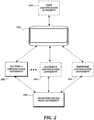
- FIGURE 2 is a block diagram of an illustrative hierarchy of CAs.
- the illustrative CAs shown in FIGURE 2 may be used to provide the device certificate 164 and user certificate 166 shown in FIGURE 1 , as well as a firmware certificate (not shown in FIGURE 1 ), which can be useful in scenarios where firmware must be digitally signed in order for a signature device to accept a firmware update.
- a signature device root authority 280 facilitates provision of one or more factory CAs 282, 284 for one or more individual factories and a firmware CA 286. Providing separate CAs for individual factories helps to isolate the potential risk of a third-party factory causing a security issue. Signature devices that have been initialized by that factory can then also be isolated.
- FIGURE 2 also shows a user CA 290.
- a user certificate and private key pair may be provided as an enhancement to a default level of security, in which a default-level key pair provided by the manufacturer may be replaced by a user certificate and private key pair.
- the term "user” or "end user” of a signature device may refer to any owner of the device (e.g., a bank or other business or organization), or any authorized person or entity that selects a CA for the user certificate, and need not refer to a person that only uses the device to make a signature, such as a customer in a bank.
- a device certificate (a public key certificate signed by a private key held by, e.g., the manufacturer of the signature device) is installed in a signature device before the signature device is put into use.
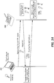
- FIGURE 3A is a flow diagram of an illustrative process for installation of a device certificate in a signature device, such as a signature tablet 300 (abbreviated as "STU" in FIGURE 3A ).
- the tablet 300 communicates with a host computer 302 at a factory.
- the host computer 302 requests the tablet 300 to generate a new device key pair and a certificate signing request (CSR).
- CSR certificate signing request
- the tablet 300 generates the new key pair and the CSR, and sends the CSR to the host computer 300.
- the host computer 302 generates a certificate signed by the CA's private key, and returns the certificate to the tablet 300.
- the tablet 300 stores the device certificate and the device key pair.
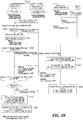
- FIGURE 3B is a flow diagram of another illustrative process for installation of a device certificate in a signature device, such as the signature tablet 100 shown in FIGURE 1 .
- the tablet communicates with a host computer at Factory A.
- a bootstrap certificate and key contained within a firmware image of the tablet are used to obtain an encrypted unique serial number (UID2) of the device from the factory host computer, acting as a TLS client.
- the factory host computer also sends an encrypted "new key" command to generate a new key pair.
- the tablet decrypts the device serial number using its bootstrap private key (F_PR) and stores the device serial number in the tablet (step 311).
- the tablet also decrypts the new key command and generates a new key pair (step 313) consisting of a device public key (D_PU) and a device private key (D_PR).
- the tablet issues a certificate signing request (CSR) for the device public key and sends this CSR to the factory host computer, which forwards it to the factory CA.
- CSR certificate signing request
- the factory CA has previously generated its own public key (W_PU) and private key (W_PR), with the public key signed by a root authority.
- the CSR includes the device public key and the device serial number.
- the factory CA encrypts the device public key with the CA private key (W_PR) and provides the CA's digital signature for the device public key.
- the factory CA encrypts the device serial number with the CA private key (W_PR) and provides the CA's digital signature for the device serial number.
- the factory CA then returns a certificate with the signed device public key (D_PU) and device serial number (UID2) to the tablet, along with a certificate with the CA's signed public key (W_PU).
- the tablet decrypts the signed device public key (D_PU) with the CA's signed public key (W_PU). If the decrypted device public key matches the version that was already on the tablet, the tablet returns a success notification to the factory host computer, which sends a command to store the device key pair with a device certificate indicating the appropriate signatures of the device public key, the device serial number, and the factory public key.
- the tablet stores the device certificate and at step 321, the tablet stores the device key pair, while the two certificates for the device are recorded by the CA at step 322.
- the tablet can operate as a TLS server when communicating with a user's host computer (e.g., a bank's host computer) acting as a TLS client.
- a user's host computer e.g., a bank's host computer
- a signature device establishes TLS communication with a user's host computer (e.g., a bank's host computer) via a USB connection.
- a user's host computer e.g., a bank's host computer
- FIGURE 4A is a flow diagram of an illustrative process in which a signature device, such as a signature tablet 300 (abbreviated as "STU" in FIGURE 4A ) establishes communication with a user's host computer 304 (e.g., a bank's host computer).
- a signature device such as a signature tablet 300 (abbreviated as "STU” in FIGURE 4A ) establishes communication with a user's host computer 304 (e.g., a bank's host computer).
- the tablet 300 is connected to the user's host computer 304, and the host computer requests the tablet 300 to generate a new device key pair and a certificate signing request (CSR).
- CSR certificate signing request
- the tablet 300 generates the new key pair and the CSR, and sends a certificate to the host computer 304.
- the host computer 304 verifies the certificate, generates a random number, generates a session key from the random number, encrypts the random number with the tablet's public key, and sends the encrypted random number to the tablet 300.
- the tablet 300 decrypts the random number and generates a session key from the random number.
- FIGURE 4B is a flow diagram of another illustrative process in which a signature device (e.g., the signature tablet 100 shown in FIGURE 1 ) establishes communication with a user's host computer (e.g., a bank's host computer).
- a tablet stores a device key pair consisting of a device public key (D_PU) and a device private key (D_PR) with a device certificate indicating the appropriate signatures of the device public key (D_PU), a device serial number (UID2), and a factory CA public key (W_PU).
- D_PU device public key
- D_PR device private key
- W_PU factory CA public key
- the tablet is connected to the user's host computer, and the host computer requests TLS communication. Responsive to this request, parameters for the TLS communication may be negotiated.
- the tablet provides the device certificate.
- the host computer then runs several checks to confirm that it is communicating with an authorized tablet.
- the host computer determines whether the certificate is valid. If it is valid, at step 414 the host computer decrypts information in the device certificate and determines whether the device public key (D_PU) and the device serial number (UID2) have been signed by the factory CA's private key (W_PR). If so, at step 415 the host computer confirms that the device certificate has not been revoked by the factory CA.
- a certificate revocation list can be used to specify certificates that are no longer authorized.
- the host computer requests an updated CRL from the factory CA and checks that the device certificate is still authorized.
- the host computer confirms that the device certificate has not been revoked by the factory CA, the host computer generates a shared secret key (KEY-USB) at step 417 and encrypts it using the device public key (D_PU) at step 419.
- the host computer then sends the encrypted shared secret key (KEY-USB) to the tablet, which decrypts it using the device private key (D PR) at step 421.
- the shared secret key can then be used for secure TLS communication.
- a signature device transmits pen event data using TLS communication to a user's host computer (e.g., a bank's host computer) via a USB connection.
- a user's host computer e.g., a bank's host computer
- FIGURE 4C is a flow diagram of an illustrative process in which a signature device (e.g., the signature tablet 100 shown in FIGURE 1 ) acting as a TLS server transmits pen event data to a user's host computer (e.g., a bank's host computer) acting as a TLS client, using the shared secret key described with reference to FIGURE 4B .
- the USB bulk transfer mechanism is used for the purpose of transmitting pen event data.
- the tablet and the host computer each store the shared secret key (KEY-USB) for secure TLS communication.
- the tablet encrypts pen data with the shared secret key (KEY-USB).
- the tablet sends the encrypted pen data via a USB bulk OUT endpoint.
- the host computer can return an acknowledgement via a USB bulk transfer mechanism, as well.
- the host computer receives the encrypted pen data via a USB bulk IN endpoint and decrypts the encrypted pen data using the shared secret key (KEY-USB). These steps can be repeated until pen data transmissions are completed.
- a user certificate and key pair may be provided as an enhancement to a default level of security (e.g., device certificates, as described above), in which a default-level key pair provided by the manufacturer may be replaced by a user certificate and key pair. This replacement can be carried out by connecting the signature device to a host computer using default-level protection, and then generating a new key pair and requesting a corresponding certificate.
- a default level of security e.g., device certificates, as described above
- This replacement can be carried out by connecting the signature device to a host computer using default-level protection, and then generating a new key pair and requesting a corresponding certificate.
- the term "user” or “end user” may refer to any owner of the signature device (e.g., a bank or other business or organization), or any authorized person or entity that selects a CA for the user certificate, and need not refer to a person that only uses the device to make a signature, such as a customer in a bank.
- a fourth illustrative embodiment in which a user certificate is installed in a signature device to replace the device certificate.
- the user's host computer sends a command to the signature device to generate a user key pair.
- the signature device generates the user key pair and returns a CSR for the new public key to the host computer.
- the host computer may then send the CSR to a second CA (the user CA) selected by the end user.
- the host computer obtains a certificate for the new public key from the user CA and forwards the certificate to the signature device.
- the signature device stores the new certificate with the user key pair.
- the device key pair is made unavailable, although it may be reinstated in some situations, such as a factory reset to restore original device configurations.
- FIGURE 5 is a flow diagram of an illustrative process in which a signature device (e.g., the signature tablet 300, abbreviated as "STU" in FIGURE 5 ) communicates with a user's host computer 304 (e.g., a bank's host computer) and creates a custom user key pair.
- a signature device e.g., the signature tablet 300, abbreviated as "STU” in FIGURE 5
- the tablet 300 is connected to the user's host computer 304, and the host computer requests the tablet 300 to generate a new device key pair and a certificate signing request (CSR).
- CSR certificate signing request
- the tablet 300 generates the new key pair and the CSR, and sends the CSR to the host computer 304, which forwards the CSR to a CA 306.
- the CA 306 generates a certificate signed by the CA's private key, and returns the certificate to the host computer 304, which forwards the certificate to the tablet 300.
- the tablet 300 stores the certificate
- a user certificate also may be obtained in a process that is similar to the more detailed process shown in FIGURE 3B for obtaining the device certificate.
- the tablet issues a certificate signing request (CSR) for the user public key and sends this CSR to the user's host computer, which forwards it to the user's CA.
- CSR certificate signing request
- the CA encrypts the user public key with the CA's private key and provides the CA's digital signature for the user public key.
- the CA then returns a certificate with the signed user public key to the tablet, along with a certificate with the CA's signed public key.
- the tablet decrypts the signed user public key with the CA's signed public key.
- the tablet If the decrypted user public key matches the version that was already on the tablet, the tablet returns a success notification to the user's host computer, which sends a command to store the user key pair with a user certificate having the appropriate signatures. The tablet then stores the user certificate and the user key pair for future use, and the device key pair and certificate are made unavailable.
- a shared secret key for TLS communication may be obtained in a process similar to the process shown in FIGURE 4B .
- the tablet can provide the user certificate to the host computer, and the host computer can determine whether the user certificate is valid, check for appropriate digital signatures by the CA, and confirm that the user certificate has not been revoked by the CA. Once that is confirmed, the host computer can generate a shared secret key and encrypt it using the user public key. The host computer can then send the encrypted shared secret key to the tablet, which can decrypt it using the user private key. The shared secret key can then be used for secure TLS communication. Once TLS communication is established between the signature device and the host computer, the signature device can then securely transmit data to the host computer via a USB connection, using a process similar to the process shown in FIGURE 4C .
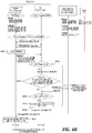
- FIGURE 6 is a flow chart of an illustrative process 600 that may be performed according to the fourth illustrative embodiment.
- a connection is established between a signature device and a host computer via an interface, such as a USB interface.
- a TLS connection is established between the signature device and the host computer via the interface. This is facilitated by a device certificate and key pair on the signature device that allows the TLS connection to be established for temporary communication, before a user certificate and key pair are obtained.
- the host computer sends a command to the signature device via the interface to generate a new key pair.
- the host computer receives a CSR from the signature device via the interface.
- the CSR includes the new public key.
- the host computer sends the CSR to a third-party CA selected by the user.
- the host computer receives a new public key certificate from the CA.
- the host computer sends the new public key certificate to the signature device via the interface.
- new TLS connections can be established between the signature device and the host computer (or other host computers) using the user certificate and key pair. These new TLS connections can be used to send encrypted pen data, or other data, over connections that have an additional level of trust, provided by the user's CA.
- a signature device transmits data using TLS communication to a user's host computer (e.g., a bank's host computer) via a USB connection.
- a user's host computer e.g., a bank's host computer
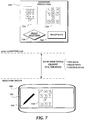
- FIGURE 7 is a block diagram of an illustrative system in which the fifth illustrative embodiment may be implemented.
- a signature device 100 communicates with a host computer 200 via a bi-directional, TLS-protected USB channel.
- the signature device 100 and the host computer 200 include components similar to those shown in FIGURE 1 , but many of these components are not shown in FIGURE 7 for ease of illustration.
- the host computer 200 includes a signature application 205 with multiple images 710, 720 of a PIN pad, image selection functionality 730, and image maps 740 that map particular characters in the PIN pad with particular regions of each image 710, 720.
- Image 710 represents a first configuration of a PIN pad
- image 720 represents a scrambled configuration of the PIN pad.
- the possibility of multiple PIN pad configurations means that if pen position data is intercepted during transmission, the pen position data cannot be easily mapped to a particular character on the PIN pad, without knowing which image was used. Although only two images are shown for ease of illustration, it should be understood and more images can be easily accommodated, and that additional scrambled PIN pad layouts may be preferable to provide additional security.
- the image selection functionality 730 selects image 720 for display on the signature device 100.
- the host computer 200 then encrypts and sends the selected image 720 to the signature device 100 for display.
- the signature device decrypts and displays the image 720.
- a user e.g., a bank customer
- This pen data can then be encrypted and sent back to the signature device, for decryption and mapping to particular characters of the PIN based on the image maps 740.
- Other software on the host computer (perhaps in combination with other computers, such as banking information servers) can then be used determine whether the PIN entered by the user is valid or not.
- FIGURE 8 is a flow chart of an illustrative process 800 that may be performed according to the fifth illustrative embodiment.
- a TLS connection is established between a signature device and a host computer running an application.
- the host computer selects an image file from among a set of image files stored in the host computer. Each image file has a different mapping between image regions and a character alphabet.
- each image file in the set of image files represents a different layout of characters for entering a PIN (e.g., for accessing a bank account.)
- the host computer encrypts the selected image.
- the host computer sends the encrypted image to the signature device over the TLS connection.
- the host computer receives encrypted pen data from the signature device over the TLS connection.
- the host computer decrypts the encrypted pen data.
- the host computer identifies at least one character based on the decrypted pen data and the mapping between image regions and the character alphabet associated with the select image file.
- a signature tablet is used in combination with an external computer (e.g., a bank's host computer).
- the signature tablet may act as a TLS server having a server certificate.
- FIGURE 9 is a block diagram of an illustrative system 900 according to the sixth embodiment.
- a signature tablet 910 communicates with an external computer 920.
- the signature tablet comprises an input sensor 912 (e.g., an EMR sensor), an input sensor controller 914 (e.g., an EMR controller), and a main controller 916.
- the main controller comprises a peripheral device interface 917 (e.g., a USB interface) and memory 918.
- the signature tablet also may include a display 919 (e.g., an LCD display).
- the input sensor controller is configured to detect a series of positions of a pen and generate a series of pen data.
- the memory 918 stores a key pair of a public key and a private key, a server certificate for the public key, and firmware.
- the firmware is configured to cause the main controller 916 to establish a connection with the external computer 920 over the peripheral device interface 917 when the peripheral device interface is detected to be connected with the external computer 920; provide the server certificate including the public key to the external computer 920 over the connection; and, in a case where a response indicating the server certificate is trusted by the external computer is received, send the series of pen data to the external computer 920.
- the external computer 920 may be programmed to receive the server certificate including the public key over the connection, determine whether the server certificate is trusted or not, send the response indicating the server certificate is trusted to the signature tablet 910 in a case where the server certificate is trusted, and receive the series of pen data.
- the firmware may be further configured to cause the main controller 916 to receive an encrypted shared secret key generated by the external computer 920 over the connection (e.g., via a secure TLS or SSL session established directly via the connection over the USB peripheral device interface) as the response indicating the server certificate is trusted by the external computer; and send the series of pen data by encrypting the series of pen data with the shared secret key.
- the firmware may be further configured to cause the main controller 916 to establish a default pipe for exchanging USB device properties and two pipes for USB bulk transfer for two-way communication with the external computer 920 over the peripheral device interface 917. The series of pen data may be sent over the TLS session established via the two pipes for USB bulk transfer.
- the signature tablet 910 may issue a certificate signing request (CSR).
- CSR certificate signing request
- the firmware may be further configured to cause the main controller 916 to generate a first key pair in response to a command, send a CSR for the public key in order to obtain the server certificate signed by a certificate authority (CA), and store the server certificate including the public key in the memory 918.
- the firmware may be further configured to cause the main controller 916 to generate a new key pair of a new public key and a new private key in response to another command, send a CSR for the new public key in order to obtain the public key signed by a second CA, and update the memory 918 to store the new key pair and a server certificate for the new public key signed by the second CA.
- the firmware may be further configured to cause the main controller 916 to retrieve a client certificate including a public key of the external computer 920 from the external computer 920, determine whether the client certificate is trusted or not, and, in case the client certificate is trusted and the response indicating that the server certificate is trusted by the external computer 920 is received, send the series of pen data to the external computer 920.
- the firmware may be further configured to cause the signature tablet 910 to decrypt encrypted image data sent from the external computer 920 over the connection to obtain image data, and display a path of the positions of the pen in a manner such that the path is overlaid with the image data when displayed on the display 919.
- the image data may represent either a first image for entering a handwriting signature or a second image showing a layout of characters for entering a PIN.
- the firmware may be further configured to cause the signature tablet to display the path of the positions of the pen in a manner such that the path is overlaid with the first image, and display a character selected by the positions in a highlighted manner.
- the embodiments described herein, or other embodiments may be implemented by any suitable computing devices, including, but not limited to, laptop computers, desktop computers, smart phones, tablet computers, dedicated signature tablets, or combinations of such devices.
- FIGURE 10 is a block diagram that illustrates aspects of an illustrative computing device 1000 appropriate for use in accordance with embodiments of the present disclosure.
- the description below is applicable to servers, personal computers, mobile phones, smart phones, tablet computers, embedded computing devices, and other currently available or yet to be developed devices that may be used in accordance with embodiments of the present disclosure.
- the computing device 1000 includes at least one processor 1002 and a system memory 1004 connected by a communication bus 1006.
- the system memory 1004 may be volatile or nonvolatile memory, such as read only memory (“ROM”), random access memory (“RAM”), EEPROM, flash memory, or other memory technology.
- ROM read only memory
- RAM random access memory
- EEPROM electrically erasable programmable read-only memory
- flash memory or other memory technology.
- system memory 1004 typically stores data and/or program modules that are immediately accessible to and/or currently being operated on by the processor 1002.
- the processor 1002 may serve as a computational center of the computing device 1000 by supporting the execution of instructions.
- the computing device 1000 may include a network interface 1010 comprising one or more components for communicating with other devices over a network.
- Embodiments of the present disclosure may access basic services that utilize the network interface 1010 to perform communications using common network protocols.
- the network interface 1010 may also include a wireless network interface configured to communicate via one or more wireless communication protocols, such as WiFi, 2G, 3G, 4G, LTE, WiMAX, Bluetooth, and/or the like.
- the computing device 1000 also includes a storage medium 1008.
- services may be accessed using a computing device that does not include means for persisting data to a local storage medium. Therefore, the storage medium 1008 depicted in FIGURE 10 is optional.
- the storage medium 1008 may be volatile or nonvolatile, removable or non-removable, implemented using any technology capable of storing information such as, but not limited to, a hard drive, solid state drive, CD-ROM, DVD, or other disk storage, magnetic tape, magnetic disk storage, and/or the like.
- computer readable medium includes volatile and nonvolatile and removable and non-removable media implemented in any method or technology capable of storing information, such as computer readable instructions, data structures, program modules, or other data.
- system memory 1004 and storage medium 1008 depicted in FIGURE 10 are examples of computer readable media.
- FIGURE 10 does not show some of the typical components of many computing devices.
- the computing device 1000 may include input devices, such as a keyboard, keypad, mouse, trackball, microphone, video camera, touchpad, touchscreen, stylus, and/or the like.
- Such input devices may be coupled to the computing device 1000 by wired or wireless connections including RF, infrared, serial, parallel, Bluetooth, USB, or other suitable connection protocols using wireless or physical connections.
- data can be captured by input devices (e.g., signature devices) and transmitted or stored for future processing.
- the processing may include encoding data, which can be subsequently decoded for presentation by output devices.
- Input devices can be separate from and communicatively coupled to computing device 1000, or can be integral components of the computing device 1000.
- the computing device 1000 may also include output devices such as a display or touchscreen.
- the output devices can be separate from and communicatively coupled to the computing device 1000, or can be integral components of the computing device 1000.
- Input functionality and output functionality may be integrated into the same input/output device (e.g., a touchscreen). Any suitable input device, output device, or combined input/output device either currently known or developed in the future may be used with described systems.
- functionality of computing devices described herein may be implemented in computing logic embodied in hardware or software instructions, which can be written in a programming language, such as C, C++, COBOL, JAVATM, PHP, Perl, Python, Ruby, HTML, CSS, JavaScript, VBScript, ASPX, Microsoft .NETTM languages such as C#, and/or the like.
- Computing logic may be compiled into executable programs or written in interpreted programming languages.
- functionality described herein can be implemented as logic modules that can be duplicated to provide greater processing capability, merged with other modules, or divided into sub modules.
- the computing logic can be stored in any type of computer readable medium (e.g., a non-transitory medium such as a memory or storage medium) or computer storage device and be stored on and executed by one or more general purpose or special purpose processors, thus creating a special purpose computing device configured to provide functionality described herein.
- a computer readable medium e.g., a non-transitory medium such as a memory or storage medium
- computer storage device e.g., a non-transitory medium such as a memory or storage medium
- embodiments described herein can be adapted to mechanisms, algorithms and encryption techniques that are incorporated into current or subsequent iterations of the TLS specification.
- PFS Perfect Forward Secrecy
- Embodiments described herein can be easily adapted to take advantage of this additional security, which is contained completely within the TLS framework.
- modules or subsystems can be separated into additional modules or subsystems or combined into fewer modules or subsystems.
- modules or subsystems can be omitted or supplemented with other modules or subsystems.
- functions that are indicated as being performed by a particular device, module, or subsystem may instead be performed by one or more other devices, modules, or subsystems.
- processing stages in the various techniques can be separated into additional stages or combined into fewer stages.
- processing stages in the various techniques can be omitted or supplemented with other techniques or processing stages.
- processing stages that are described as occurring in a particular order can instead occur in a different order.
- processing stages that are described as being performed in a series of steps may instead be handled in a parallel fashion, with multiple modules or software processes concurrently handling one or more of the illustrated processing stages.
- processing stages that are indicated as being performed by a particular device or module may instead be performed by one or more other devices or modules.
Landscapes
- Engineering & Computer Science (AREA)
- Computer Security & Cryptography (AREA)
- Signal Processing (AREA)
- Computer Networks & Wireless Communication (AREA)
- Computer Hardware Design (AREA)
- General Engineering & Computer Science (AREA)
- General Physics & Mathematics (AREA)
- Physics & Mathematics (AREA)
- Computing Systems (AREA)
- Theoretical Computer Science (AREA)
- Business, Economics & Management (AREA)
- Accounting & Taxation (AREA)
- Software Systems (AREA)
- Strategic Management (AREA)
- Finance (AREA)
- General Business, Economics & Management (AREA)
- Health & Medical Sciences (AREA)
- Bioethics (AREA)
- General Health & Medical Sciences (AREA)
- Storage Device Security (AREA)
- User Interface Of Digital Computer (AREA)
- Management, Administration, Business Operations System, And Electronic Commerce (AREA)
Description
- Electronic handwriting is increasingly important in a variety of contexts. For example, electronic handwriting is now commonly used in place of pen and paper to obtain a credit card holder's affirmation of a credit card transaction. As another example, signature pads and tablets are used in banks, retail stores, and other locations to obtain signatures on legally binding documents. Given the sensitive nature of such applications, authentication of signature devices and security of data being transferred between signature devices and other computers has become a critical issue for suppliers and users of such devices. Proprietary security and encryption schemes are possible, but they require significant effort and expense, as well as a high level of trust between designers of such schemes and their customers.
-
U.S. Patent No. 8,700,905 discloses, for example, a signature capture apparatus that captures a handwritten signature and encrypts the signature data.U.S. Patent No. 7,933,840 discloses, for example, a signature device which encrypts signature data with transaction data provided by a host computer. -
CN 103 888 422 A discloses a method comprising steps: after a client establishes a connection with a server, the client receives a certificate updating notification sent by the server when a certificate needs updating; after receiving the certificate updating notification, the client sends identity identification information to the server; the client receives a certificate updating command which is sent when the server determines the client is qualified for carrying out certificate updating, and generates a certificate signature request comprising a security certificate preparation file after receiving the certificate updating command; the client sends the certificate signature request to the server; and the client receives the security certificate file sent by the server. -
CN 204 442 397 U discloses an electronic signature encryption device comprising a handwriting pen and an electronic signature encryption screen. The electronic signature encryption screen comprises an interface module for connecting with an external computer so as to enable USB signals output by the computer to be accessed, a control panel connected with the interface module and used for converting the USB signals into LVDS signals, a touch screen connected with the control panel and used for displaying the LVDS signals and receiving handwriting information input by the handwriting pen under a screen display interface, and an encryption module connected with the touch screen and used for encrypting the handwriting information and converting the encrypted handwriting information into the USB signals, wherein the output end of the encryption module is connected with the interface module. -
US 2015/154414 A1 discloses a computer-implemented authentication method comprising the step of enabling a user to input an identifier into an electronic device having a screen and a keypad operable within a keypad zone of the screen; by operating at least one key of the keypad via an image of at least part of a scrambled keypad which is displayed at least partially within the keypad zone. -
US 2006/037067 A1 discloses a system in which, in an exchange of data between a client terminal and a secure database server, the data is encoded using positional information generated by a combination generator in a separate security server. - This summary is provided to introduce a selection of concepts in a simplified form that are further described below in the Detailed Description. This summary is not intended to identify key features of the claimed subject matter, nor is it intended to be used as an aid in determining the scope of the claimed subject matter.
- In one aspect, a connection is established between a signature device and a host computer via an interface (e.g., a universal serial bus (USB) interface), and a transport layer security (TLS) connection is established between the signature device and the host computer via the interface. The host computer sends a command via the interface to the signature device to generate a new key pair, receives a certificate signing request (CSR) from the signature device via the interface, sends the CSR to a user certificate authority (CA), receives a public key certificate from the user CA, and sends the public key certificate to the signature device via the interface.
- In another aspect, the invention relates to a computer-implemented method, wherein a connection is established between a signature device and a host computer via a USB interface, and a TLS connection is established between the signature device and the host computer via the USB interface. The signature device acts as a TLS server, and the host computer acts as a TLS client. Preferably, data is received from or transmitted to the signature device via a USB bulk transfer.
- In another aspect, a TLS connection is established (e.g., via a USB interface) between a signature device and a host computer running an application. The host computer selects an image file from a set of image files (e.g., representing different layouts of characters for entering a PIN) stored in the host computer, wherein each image file in the set of image files has a different mapping between image regions and a character alphabet, The host computer encrypts the selected image, sends the selected image to the signature device over the TLS connection, receives encrypted pen data (e.g., representing user selection of characters in a PIN) from the signature device over the TLS connection, decrypts the encrypted pen data, and identifies at least one character based on the decrypted pen data and the mapping between image regions and the character alphabet associated with the selected image file.
- In another aspect, after a TLS connection is established (e.g., via a USB interface) between a signature device and a host computer running an application, the signature device receives an encrypted image selected from a set of images stored in the host computer over the TLS connection, decrypts the encrypted image, and sends encrypted pen data to the host computer over the TLS connection. Each image in the set of images has a different mapping between image regions and a character alphabet, and the encrypted pen data represents user selection of characters in a PIN.
- In another aspect, a signature tablet for use with an external computer comprises a sensor section configured to obtain a series of pen data and a controller configured to generate a public key and a private key, obtain a third party certificate for the public key, establish a secure connection with the external computer by using the public key signed by the third party, and send the series of pen data over the secure connection as the series of pen data is obtained.
- In some aspects, data such as pen data, control data, or image data may be received or transmitted via a USB bulk transfer mechanism.
- In another aspect, a signature tablet communicates with an external computer. The signature tablet comprises an input sensor (e.g., an electromagnetic resonance (EMR) sensor), an input sensor controller (e.g., an EMR controller), and a main controller. The main controller comprises a peripheral device interface (e.g., a USB interface) and memory. The signature tablet also may include a display (e.g., an LCD display). The input sensor controller is configured to detect a series of positions of a pen and generate a series of pen data. The memory stores a key pair of a public key and a private key, a server certificate for the public key, and firmware. The firmware is configured to cause the main controller to establish a connection with the external computer over the peripheral device interface when the peripheral device interface is detected to be connected with the external computer, provide the server certificate including the public key to the external computer over the connection, and, in case a response indicating the server certificate is trusted by the external computer is received, send the series of pen data to the external computer. The external computer may be programmed to receive the server certificate including the public key over the connection, determine whether the server certificate is trusted or not, send the response indicating the server certificate is trusted to the signature tablet in a case where the server certificate is trusted, and receive the series of pen data.
- The firmware may be further configured to cause the main controller to receive an encrypted shared secret key generated by the external computer over the connection (e.g., via a secure TLS or SSL (Secure Sockets Layer) session established directly via the connection over the USB peripheral device interface) as the response indicating the server certificate is trusted by the external computer; and send the series of pen data by encrypting the series of pen data with the shared secret key. The firmware may be further configured to cause the main controller to establish a default pipe for exchanging USB device properties and two pipes for USB bulk transfer for two-way communication with the external computer over the peripheral device interface. The series of pen data may be sent over the TLS session established via the two pipes for USB bulk transfer.
- The signature tablet may issue a CSR. For example, the firmware may be further configured to cause the main controller to generate a first key pair in response to a command, send a CSR for the public key in order to obtain the server certificate signed by a CA, and store the server certificate including the public key in the memory. The firmware may be further configured to cause the main controller to generate a new key pair of a new public key and a new private key in response to another command, send a CSR for the new public key in order to obtain the public key signed by a second CA, and update the memory to store the new key pair and a server certificate for the new public key signed by the second CA.
- For mutual authentication, the firmware may be further configured to cause the main controller to retrieve a client certificate including a public key of the external computer from the external computer, determine whether the client certificate is trusted or not, and, in case the client certificate is trusted and the response indicating that the server certificate is trusted by the external computer is received, send the series of pen data to the external computer.
- For PIN entry, the firmware may be further configured to cause the signature tablet to decrypt encrypted image data sent from the external computer over the connection to obtain image data, and display a path of the positions of the pen in a manner such that the path is overlaid with the image data when displayed on the display. The image data may represent either a first image for entering a handwriting signature or a second image showing a layout of characters for entering a PIN. The firmware may be further configured to cause the signature tablet to display the path of the positions of the pen in a manner such that the path is overlaid with the first image, and display a character selected by the positions in a highlighted manner.
- The foregoing aspects and many of the attendant advantages of this invention will become more readily appreciated as the same become better understood by reference to the following detailed description, when taken in conjunction with the accompanying drawings, wherein:
-
FIGURE 1 is a block diagram of an illustrative system in which described embodiments may be implemented; -
FIGURE 2 is a block diagram of an illustrative hierarchy of certificate authorities that may be used in described embodiments; -
FIGURES 3A and3B are flow diagrams of processes according to a first illustrative embodiment; -
FIGURES 4A and4B are flow diagrams of processes according to a second illustrative embodiment; -
FIGURE 4C is a flow diagram of a process according to a third illustrative embodiment; -
FIGURES 5 and6 are flow diagrams of processes according to a fourth illustrative embodiment; -
FIGURE 7 is a block diagram of a system in which a fifth illustrative embodiment may be implemented; -
FIGURE 8 is a flow chart of a process that may be performed according to a fifth illustrative embodiment; -
FIGURE 9 is a block diagram of an illustrative system according to a sixth embodiment; and -
FIGURE 10 is a block diagram that illustrates aspects of an illustrative computing device appropriate for use in accordance with described embodiments. - The detailed description set forth below in connection with the appended drawings, where like numerals reference like elements, is intended as a description of various embodiments of the disclosed subject matter and is not intended to represent the only embodiments. Each embodiment described in this disclosure is provided merely as an example or illustration and should not be construed as preferred or advantageous over other embodiments. The illustrative examples provided herein are not intended to be exhaustive or to limit the claimed subject matter to the precise forms disclosed.
- In the following description, numerous specific details are set forth in order to provide a thorough understanding of exemplary embodiments of the present disclosure. It will be apparent to one skilled in the art, however, that many embodiments of the present disclosure may be practiced without some or all of the specific details. In some instances, well-known process steps have not been described in detail in order not to unnecessarily obscure various aspects of the present disclosure. Further, it will be appreciated that embodiments of the present disclosure may employ any combination of features described herein.
- As noted above,
U.S. Patent No. 8,700,905 discloses, for example, a signature capture apparatus that captures a handwritten signature and encrypts the signature data, andU.S. Patent No. 7,933,840 discloses, for example, a signature device which encrypts signature data with transaction data provided by a host computer. However, no practical solutions have been provided for a mechanism for authentication, either one (one-way or both way) mechanism between signature tablet and host computer. Using a pre-shared key or temporary shared transaction data as an encryption key is not enough to protect against man-in-the-middle attacks, or to account for situations in which a signature tablet has been replaced by third party before the tablet has been newly installed (e.g., in a bank or user site) after the signature tablet had shipped. - Further, although data can be transmitted via USB from a signature device to a host PC using different USB transfer mechanisms, to protect the transmission it has previously been necessary to use a complex approach of providing different encryption schemes for encrypting and transmitting various types of data (e.g., configuration or control data, pen data, image data, or other data) between the signature device and the host PC using various USB transfer mechanisms (e.g., control transfers, interrupt transfers). A simpler scheme for securely transmitting data over USB is desirable.
- In general computing, TLS (Transport Layer Security) is an industry standard protocol for protection of bi-directional communication channels. Formerly known as SSL (Secure Sockets Layer), TLS is often used in web browsers and web servers to protect TCP/IP links as secure HTTPS connections. TLS may be implemented using open-source libraries and toolkits, such as OpenSSL, provided by the OpenSSL Software Foundation, or wolfSSL (formerly CyaSSL), provided by wolfSSL Inc. A current version of the TLS standard, TLS 1.2, is defined in RFC 5246, which is a document available from the Internet Engineering Task Force (IETF).
- TLS uses public key cryptography, which requires assurance that the party encrypting the message is using the encryption algorithm of the correct party, Otherwise, the message may be vulnerable to man-in-the-middle attacks in which an unauthorized party impersonates the actual parties to the transaction, allowing the unauthorized party to view an unencrypted message. PKI (public key infrastructure) provides a solution in the form of a trusted certification authority (CA). The CA provides a public key certificate for the message. The public key certificate includes the CA's digital signature along with a party's public key and a text string identifier of the party. The public key certificate assures the encrypting party that the public key belongs to the intended recipient.
- However, despite the existence of protocols like TLS in general computing applications, no easy solution has been found for securing communication channels in the specialized field of electronic signature devices.
- In embodiments described herein, solutions for one or more of the technical problems described above are provided. For example, in some embodiments a TLS protocol is used for authentication and to protect links between signature devices and the computers they communicate with. Using TLS for these purposes has several advantages. For example, data can be protected in both directions between the signature device the computer it is communicating with. As another example, TLS is an industry standard that is well supported and understood, and it may be implemented using open-source libraries and toolkits, such as OpenSSL or wolfSSL.
- Signature devices often communicate with other computers using USB (Universal Serial Bus) ports. In described embodiments, TLS is for authentication over USB and to protect the USB connection between signature devices and other computers. Described embodiments also allow mutual authentication between signature devices and other computers over USB channels.
- Described embodiments can be used to provide mutual authentication of signature devices and the computers they communicate with, and as a defense against security breaches such as attempted connection of unauthorized computers to signature devices, and malicious hijacking of USB connections.
- The present disclosure provides different levels of security that may be used. At a first or default level, a signature device can provide security with public key certificates signed by a private key held by the manufacturer of the signature device, and a public verification key, which may be distributed with host computer software. At the default level, the manufacturer is the CA for original certificates on the signature device. At a second level, a user certificate and private key pair is provided as an enhancement to the default level. At the second level, the default-level key pair provided by the manufacturer may be replaced by a second-level key pair that is generated in the signature device. At any level of security, private key parts of the key pairs may be generated and stored in the signature device, which can help to ensure that the key pairs are properly generated and remain secure.
- In a TLS link, a device designated as a client typically authenticates a device designated as a server. In some embodiments described herein, a signature device acts as a TLS server and a host computer acts as a TLS client. If authentication of the signature device is desired, the host computer may accept a certificate from the signature device only if it has been signed by a CA. Similarly, if authentication of the host computer by the signature device is desired, the signature device may accept a certificate from a host computer only if it has been signed by a CA. Mutual authentication may include both of these forms of authentication.
- Client-side certificates also can be provided. In one illustrative scenario, a command (e.g., a command to generate a key pair) sent to the signature device specifies a requirement for client-side certificates in TLS connections. When the client (e.g., a host PC) passes a certificated key back to the signature device, the signature device can store the root certificate in a certification key chain, which can be used as a verification key to check authenticity of TLS clients that may connect to the signature device. A certificate revocation list (CRL) can be used to specify certificates that are no longer authorized. This can provide protection against unauthorized computers connecting to the signature device.
- As used herein, the term "signature device" refers to a device that captures handwriting input for signatures. Signature devices may be implemented as dedicated signature collection devices, such as signature pad devices, or as general purpose devices, such as suitably configured smart phones or tablet computers. Signature devices are not necessarily strictly input devices, and may include other functionality (e.g., display functionality, data transmission functionality, etc.). Further details on illustrative signature devices are provided below.
-
FIGURE 1 is a block diagram of an illustrative system in which described embodiments may be implemented. In the example shown inFIGURE 1 ,signature device 100 communicates with ahost computer 200 via a bi-directional, TLS-protected USB channel. Thehost computer 200 includes asignature application 205, asignature control instance 210 and related libraries (e.g., signature SDK libraries), and aTLS communication handler 220 that allows the host computer to communicate with thesignature device 100 over a TLS channel. In this example, the TLS channel is provided over a USB connection via USB ports of thehost computer 200 and thesignature device 100. AlthoughFIGURE 1 shows a single host computer and signature device for ease of illustration, it should be understood, in the context of this example and other examples described herein, that one or more additional signature devices and host computers may be present, that a host computer may communicate with more than one signature device, and that a signature device may communicate with more than one host computer. - The
signature control instance 210 may include a control module (not shown) that controls thesignature device 100 and a data module (not shown) that receives signature data from the signature device and may also send image data to signature device for display. The content of the data handled by thecontrol instance 210 may depend, for example, on the configuration or capabilities of thesignature application 205 or thesignature device 100. Signature data received from thesignature device 100 typically includes pen event data (e.g., coordinate data and pressure data) and may also include other data, such as an image of a signature, biometric data, etc. - In the example shown in
FIGURE 1 , the signature device includes anLCD screen 101 that may display, for example, an electronic document with a signature area in which a signature can be made with apen device 102. Thesignature device 100 includes asystem control module 110 for general operation of the signature device and aTLS communication handler 120 that allows the signature device to communicate with thehost computer 200 over the TLS channel. Thesystem control module 110 controls thesignature device 100 and receives sensor data from one or more sensor modules (not shown), which may be included in thesignature device 100 or, in some cases, in other devices, such as thepen 102. The sensor data can be translated into pen event data, such as coordinate data and pressure data. - In general, signature devices may use electromagnetic resonance (EMR) technology, in which a digitizer incorporates a sensor board that detects the pen's movement, and energy is induced in the pen's resonant circuit by a magnetic field generated by the sensor board surface. The pen's resonant circuit then makes use of this energy to return a magnetic signal to the sensor board surface. The board detects the pen's coordinate position at regular time intervals even if the electronic pen does not touch the sensor board surface, so long as the pen remains within close enough proximity to the sensor board, such that signals can still be received from the pen. (The effective signal range can vary depending on the particular technology being used, but is generally on the order of several millimeters.)
- Alternatively, other handwriting input technology can be used. For example, an electronic pen may use other wireless technology or may be connected by a wire to a digitizer. As another example, an electronic pen may or may not be detectable away from the surface of a digitizer. As another example, an electronic pen may be powered or unpowered. Powered pens may receive power via a wire connected to an external power source or via an on-board battery. As another example, it is possible to input handwriting data without an electronic pen (e.g., via a stylus on a pressure sensitive digital writing pad, a touchscreen, or some other input device that does not require an electronic pen).
- However the handwriting data may be collected, handwriting data provided by signature devices may include pen event information, device information, and/or contextual information about the context in which the handwriting was made. Pen event information may include the x/y position of the pen-tip on or above the digitizer surface and the time since the start of the handwriting. In addition to x/y-coordinate values, pen event information may optionally include additional information subject to the capabilities of the signature device, such as pressure (pen force), angles (azimuth, altitude, and/or rotation) and pen-down status. Pen event information is typically collected at regular intervals during a signing process. The sampling rates at which pen event information may be collected may vary depending on system design and configuration.
- Returning to the example shown in
FIGURE 1 , thesignature device 100 has a bootstrap certificate and key 160 that are hard-coded and contained within a firmware image, and are only used in an initial device setup to set a device certificate andprivate key 164 and a unique serial number 162 (labeled UID2 inFIGURE 1 ) of the device. As noted above and explained in further detail below, the device certificate is installed (e.g., at a factory) before thesignature device 100 is put into use. - As noted above and explained in further detail below, depending on the level of security desired and the design of the overall system, the
signature device 100 also may store a user certificate and private key 166 - a key pair that is created on the signature device and signed by the end user's CA. For client-side certificates, thesignature device 100 also may store a client-side CRL (certificate revocation list) 168 to specify certificates that are no longer authorized. This can provide protection against unauthorized computers connecting to thesignature device 100. Although thesignature device 100 may include more than one certificate, only one can be used at a time. If present, theuser certificate 166 will be used. Otherwise, thedevice certificate 164 will be used. As noted above, thebootstrap certificate 160 is only used in an initial device setup to set thedevice certificate 164 andID 162. -
FIGURE 2 is a block diagram of an illustrative hierarchy of CAs. The illustrative CAs shown inFIGURE 2 may be used to provide thedevice certificate 164 anduser certificate 166 shown inFIGURE 1 , as well as a firmware certificate (not shown inFIGURE 1 ), which can be useful in scenarios where firmware must be digitally signed in order for a signature device to accept a firmware update. In the example shown inFIGURE 2 , a signaturedevice root authority 280 facilitates provision of one ormore factory CAs firmware CA 286. Providing separate CAs for individual factories helps to isolate the potential risk of a third-party factory causing a security issue. Signature devices that have been initialized by that factory can then also be isolated. -
FIGURE 2 also shows auser CA 290. As noted above and explained in further detail below, a user certificate and private key pair may be provided as an enhancement to a default level of security, in which a default-level key pair provided by the manufacturer may be replaced by a user certificate and private key pair. In the context of generating user certificates, it should be understood that the term "user" or "end user" of a signature device may refer to any owner of the device (e.g., a bank or other business or organization), or any authorized person or entity that selects a CA for the user certificate, and need not refer to a person that only uses the device to make a signature, such as a customer in a bank. - In this section, a first illustrative embodiment is described in which a device certificate (a public key certificate signed by a private key held by, e.g., the manufacturer of the signature device) is installed in a signature device before the signature device is put into use.
-
FIGURE 3A is a flow diagram of an illustrative process for installation of a device certificate in a signature device, such as a signature tablet 300 (abbreviated as "STU" inFIGURE 3A ). In the example shown inFIGURE 3A , thetablet 300 communicates with ahost computer 302 at a factory. Thehost computer 302 requests thetablet 300 to generate a new device key pair and a certificate signing request (CSR). Thetablet 300 generates the new key pair and the CSR, and sends the CSR to thehost computer 300. Thehost computer 302 generates a certificate signed by the CA's private key, and returns the certificate to thetablet 300. Thetablet 300 stores the device certificate and the device key pair. -
FIGURE 3B is a flow diagram of another illustrative process for installation of a device certificate in a signature device, such as thesignature tablet 100 shown inFIGURE 1 . In the example shown inFIGURE 3B , the tablet communicates with a host computer at Factory A. A bootstrap certificate and key contained within a firmware image of the tablet are used to obtain an encrypted unique serial number (UID2) of the device from the factory host computer, acting as a TLS client. The factory host computer also sends an encrypted "new key" command to generate a new key pair. The tablet decrypts the device serial number using its bootstrap private key (F_PR) and stores the device serial number in the tablet (step 311). The tablet also decrypts the new key command and generates a new key pair (step 313) consisting of a device public key (D_PU) and a device private key (D_PR). - At
step 314, the tablet issues a certificate signing request (CSR) for the device public key and sends this CSR to the factory host computer, which forwards it to the factory CA. (Separately, as shown inFIGURE 3 , the factory CA has previously generated its own public key (W_PU) and private key (W_PR), with the public key signed by a root authority.) The CSR includes the device public key and the device serial number. Atstep 315, the factory CA encrypts the device public key with the CA private key (W_PR) and provides the CA's digital signature for the device public key. Atstep 316, the factory CA encrypts the device serial number with the CA private key (W_PR) and provides the CA's digital signature for the device serial number. The factory CA then returns a certificate with the signed device public key (D_PU) and device serial number (UID2) to the tablet, along with a certificate with the CA's signed public key (W_PU). - At
step 317, the tablet decrypts the signed device public key (D_PU) with the CA's signed public key (W_PU). If the decrypted device public key matches the version that was already on the tablet, the tablet returns a success notification to the factory host computer, which sends a command to store the device key pair with a device certificate indicating the appropriate signatures of the device public key, the device serial number, and the factory public key. Atstep 319, the tablet stores the device certificate and atstep 321, the tablet stores the device key pair, while the two certificates for the device are recorded by the CA atstep 322. - In this state, the tablet can operate as a TLS server when communicating with a user's host computer (e.g., a bank's host computer) acting as a TLS client.
- In this section, a second illustrative embodiment is described in which a signature device establishes TLS communication with a user's host computer (e.g., a bank's host computer) via a USB connection.
-
FIGURE 4A is a flow diagram of an illustrative process in which a signature device, such as a signature tablet 300 (abbreviated as "STU" inFIGURE 4A ) establishes communication with a user's host computer 304 (e.g., a bank's host computer). In the example shown inFIGURE 4A , thetablet 300 is connected to the user'shost computer 304, and the host computer requests thetablet 300 to generate a new device key pair and a certificate signing request (CSR). Thetablet 300 generates the new key pair and the CSR, and sends a certificate to thehost computer 304. Thehost computer 304 verifies the certificate, generates a random number, generates a session key from the random number, encrypts the random number with the tablet's public key, and sends the encrypted random number to thetablet 300. Thetablet 300 decrypts the random number and generates a session key from the random number. -
FIGURE 4B is a flow diagram of another illustrative process in which a signature device (e.g., thesignature tablet 100 shown inFIGURE 1 ) establishes communication with a user's host computer (e.g., a bank's host computer). In the example shown inFIGURE 4B , a tablet stores a device key pair consisting of a device public key (D_PU) and a device private key (D_PR) with a device certificate indicating the appropriate signatures of the device public key (D_PU), a device serial number (UID2), and a factory CA public key (W_PU). - The tablet is connected to the user's host computer, and the host computer requests TLS communication. Responsive to this request, parameters for the TLS communication may be negotiated. At
step 411, the tablet provides the device certificate. The host computer then runs several checks to confirm that it is communicating with an authorized tablet. Atstep 413, the host computer determines whether the certificate is valid. If it is valid, atstep 414 the host computer decrypts information in the device certificate and determines whether the device public key (D_PU) and the device serial number (UID2) have been signed by the factory CA's private key (W_PR). If so, atstep 415 the host computer confirms that the device certificate has not been revoked by the factory CA. As mentioned above, a certificate revocation list (CRL) can be used to specify certificates that are no longer authorized. In the example shown inFIGURE 4B , the host computer requests an updated CRL from the factory CA and checks that the device certificate is still authorized. - Once the host computer confirms that the device certificate has not been revoked by the factory CA, the host computer generates a shared secret key (KEY-USB) at
step 417 and encrypts it using the device public key (D_PU) at step 419. The host computer then sends the encrypted shared secret key (KEY-USB) to the tablet, which decrypts it using the device private key (D PR) atstep 421. The shared secret key can then be used for secure TLS communication. - In this section, a third illustrative embodiment is described in which a signature device transmits pen event data using TLS communication to a user's host computer (e.g., a bank's host computer) via a USB connection.
-
FIGURE 4C is a flow diagram of an illustrative process in which a signature device (e.g., thesignature tablet 100 shown inFIGURE 1 ) acting as a TLS server transmits pen event data to a user's host computer (e.g., a bank's host computer) acting as a TLS client, using the shared secret key described with reference toFIGURE 4B . In the example shown inFIGURE 4C , the USB bulk transfer mechanism is used for the purpose of transmitting pen event data. The tablet and the host computer each store the shared secret key (KEY-USB) for secure TLS communication. Atstep 431, the tablet encrypts pen data with the shared secret key (KEY-USB). Atstep 432, the tablet sends the encrypted pen data via a USB bulk OUT endpoint. The host computer can return an acknowledgement via a USB bulk transfer mechanism, as well. Atstep 433, the host computer receives the encrypted pen data via a USB bulk IN endpoint and decrypts the encrypted pen data using the shared secret key (KEY-USB). These steps can be repeated until pen data transmissions are completed. - As noted above, a user certificate and key pair may be provided as an enhancement to a default level of security (e.g., device certificates, as described above), in which a default-level key pair provided by the manufacturer may be replaced by a user certificate and key pair. This replacement can be carried out by connecting the signature device to a host computer using default-level protection, and then generating a new key pair and requesting a corresponding certificate. As noted above, it should be understood that the term "user" or "end user" may refer to any owner of the signature device (e.g., a bank or other business or organization), or any authorized person or entity that selects a CA for the user certificate, and need not refer to a person that only uses the device to make a signature, such as a customer in a bank.
- In this section, a fourth illustrative embodiment is described in which a user certificate is installed in a signature device to replace the device certificate. In an illustrative scenario, the user's host computer sends a command to the signature device to generate a user key pair. The signature device generates the user key pair and returns a CSR for the new public key to the host computer. The host computer may then send the CSR to a second CA (the user CA) selected by the end user. The host computer obtains a certificate for the new public key from the user CA and forwards the certificate to the signature device. The signature device stores the new certificate with the user key pair. The device key pair is made unavailable, although it may be reinstated in some situations, such as a factory reset to restore original device configurations.
-
FIGURE 5 is a flow diagram of an illustrative process in which a signature device (e.g., thesignature tablet 300, abbreviated as "STU" inFIGURE 5 ) communicates with a user's host computer 304 (e.g., a bank's host computer) and creates a custom user key pair. In the example shown inFIGURE 5 , thetablet 300 is connected to the user'shost computer 304, and the host computer requests thetablet 300 to generate a new device key pair and a certificate signing request (CSR). Thetablet 300 generates the new key pair and the CSR, and sends the CSR to thehost computer 304, which forwards the CSR to aCA 306. TheCA 306 generates a certificate signed by the CA's private key, and returns the certificate to thehost computer 304, which forwards the certificate to thetablet 300. Thetablet 300 stores the certificate and the custom user key pair. - A user certificate also may be obtained in a process that is similar to the more detailed process shown in
FIGURE 3B for obtaining the device certificate. In such a scenario, once the user key pair is generated, the tablet issues a certificate signing request (CSR) for the user public key and sends this CSR to the user's host computer, which forwards it to the user's CA. The CA encrypts the user public key with the CA's private key and provides the CA's digital signature for the user public key. The CA then returns a certificate with the signed user public key to the tablet, along with a certificate with the CA's signed public key. The tablet decrypts the signed user public key with the CA's signed public key. If the decrypted user public key matches the version that was already on the tablet, the tablet returns a success notification to the user's host computer, which sends a command to store the user key pair with a user certificate having the appropriate signatures. The tablet then stores the user certificate and the user key pair for future use, and the device key pair and certificate are made unavailable. - In this illustrative embodiment, a shared secret key for TLS communication may be obtained in a process similar to the process shown in
FIGURE 4B . For example, the tablet can provide the user certificate to the host computer, and the host computer can determine whether the user certificate is valid, check for appropriate digital signatures by the CA, and confirm that the user certificate has not been revoked by the CA. Once that is confirmed, the host computer can generate a shared secret key and encrypt it using the user public key. The host computer can then send the encrypted shared secret key to the tablet, which can decrypt it using the user private key. The shared secret key can then be used for secure TLS communication. Once TLS communication is established between the signature device and the host computer, the signature device can then securely transmit data to the host computer via a USB connection, using a process similar to the process shown inFIGURE 4C . -
FIGURE 6 is a flow chart of anillustrative process 600 that may be performed according to the fourth illustrative embodiment. In the example shown inFIGURE 6 , at step 610 a connection is established between a signature device and a host computer via an interface, such as a USB interface. Atstep 620, a TLS connection is established between the signature device and the host computer via the interface. This is facilitated by a device certificate and key pair on the signature device that allows the TLS connection to be established for temporary communication, before a user certificate and key pair are obtained. Atstep 630, the host computer sends a command to the signature device via the interface to generate a new key pair. Atstep 640, after the new key pair is generated by the signature device, the host computer receives a CSR from the signature device via the interface. The CSR includes the new public key. Atstep 650, the host computer sends the CSR to a third-party CA selected by the user. Atstep 660, the host computer receives a new public key certificate from the CA. Atstep 670, the host computer sends the new public key certificate to the signature device via the interface. At this point, new TLS connections can be established between the signature device and the host computer (or other host computers) using the user certificate and key pair. These new TLS connections can be used to send encrypted pen data, or other data, over connections that have an additional level of trust, provided by the user's CA. - In this section, a fifth illustrative embodiment is described in which a signature device transmits data using TLS communication to a user's host computer (e.g., a bank's host computer) via a USB connection.
-
FIGURE 7 is a block diagram of an illustrative system in which the fifth illustrative embodiment may be implemented. As shown inFIGURE 7 , asignature device 100 communicates with ahost computer 200 via a bi-directional, TLS-protected USB channel. Thesignature device 100 and thehost computer 200 include components similar to those shown inFIGURE 1 , but many of these components are not shown inFIGURE 7 for ease of illustration. In the example shown inFIGURE 7 , thehost computer 200 includes asignature application 205 withmultiple images image selection functionality 730, andimage maps 740 that map particular characters in the PIN pad with particular regions of eachimage -
Image 710 represents a first configuration of a PIN pad, andimage 720 represents a scrambled configuration of the PIN pad. The possibility of multiple PIN pad configurations means that if pen position data is intercepted during transmission, the pen position data cannot be easily mapped to a particular character on the PIN pad, without knowing which image was used. Although only two images are shown for ease of illustration, it should be understood and more images can be easily accommodated, and that additional scrambled PIN pad layouts may be preferable to provide additional security. - The
image selection functionality 730 selectsimage 720 for display on thesignature device 100. Thehost computer 200 then encrypts and sends the selectedimage 720 to thesignature device 100 for display. The signature device decrypts and displays theimage 720. A user (e.g., a bank customer) can then enter a PIN by touching the areas of the image corresponding to the desired characters, generating pen data. This pen data can then be encrypted and sent back to the signature device, for decryption and mapping to particular characters of the PIN based on theimage maps 740. Other software on the host computer (perhaps in combination with other computers, such as banking information servers) can then be used determine whether the PIN entered by the user is valid or not. -
FIGURE 8 is a flow chart of anillustrative process 800 that may be performed according to the fifth illustrative embodiment. In the example shown inFIGURE 8 , at step 810 a TLS connection is established between a signature device and a host computer running an application. For example, if the signature device and the host computer are connected via a USB interface, the TLS connection may be established via the USB interface. Atstep 820, the host computer selects an image file from among a set of image files stored in the host computer. Each image file has a different mapping between image regions and a character alphabet. In at least one embodiment, each image file in the set of image files represents a different layout of characters for entering a PIN (e.g., for accessing a bank account.) Atstep 830, the host computer encrypts the selected image. Atstep 840, the host computer sends the encrypted image to the signature device over the TLS connection. Atstep 850, the host computer receives encrypted pen data from the signature device over the TLS connection. Atstep 860, the host computer decrypts the encrypted pen data. Atstep 870, the host computer identifies at least one character based on the decrypted pen data and the mapping between image regions and the character alphabet associated with the select image file. - In this section, a sixth illustrative embodiment is described in which a signature tablet is used in combination with an external computer (e.g., a bank's host computer). The signature tablet may act as a TLS server having a server certificate.
-
FIGURE 9 is a block diagram of anillustrative system 900 according to the sixth embodiment. In the example shown inFIGURE 9 , asignature tablet 910 communicates with anexternal computer 920. The signature tablet comprises an input sensor 912 (e.g., an EMR sensor), an input sensor controller 914 (e.g., an EMR controller), and amain controller 916. The main controller comprises a peripheral device interface 917 (e.g., a USB interface) and memory 918. The signature tablet also may include a display 919 (e.g., an LCD display). - In this illustrative embodiment, the input sensor controller is configured to detect a series of positions of a pen and generate a series of pen data. The memory 918 stores a key pair of a public key and a private key, a server certificate for the public key, and firmware. The firmware is configured to cause the
main controller 916 to establish a connection with theexternal computer 920 over theperipheral device interface 917 when the peripheral device interface is detected to be connected with theexternal computer 920; provide the server certificate including the public key to theexternal computer 920 over the connection; and, in a case where a response indicating the server certificate is trusted by the external computer is received, send the series of pen data to theexternal computer 920. Theexternal computer 920 may be programmed to receive the server certificate including the public key over the connection, determine whether the server certificate is trusted or not, send the response indicating the server certificate is trusted to thesignature tablet 910 in a case where the server certificate is trusted, and receive the series of pen data. - The firmware may be further configured to cause the
main controller 916 to receive an encrypted shared secret key generated by theexternal computer 920 over the connection (e.g., via a secure TLS or SSL session established directly via the connection over the USB peripheral device interface) as the response indicating the server certificate is trusted by the external computer; and send the series of pen data by encrypting the series of pen data with the shared secret key. The firmware may be further configured to cause themain controller 916 to establish a default pipe for exchanging USB device properties and two pipes for USB bulk transfer for two-way communication with theexternal computer 920 over theperipheral device interface 917. The series of pen data may be sent over the TLS session established via the two pipes for USB bulk transfer. - The
signature tablet 910 may issue a certificate signing request (CSR). For example, the firmware may be further configured to cause themain controller 916 to generate a first key pair in response to a command, send a CSR for the public key in order to obtain the server certificate signed by a certificate authority (CA), and store the server certificate including the public key in the memory 918. The firmware may be further configured to cause themain controller 916 to generate a new key pair of a new public key and a new private key in response to another command, send a CSR for the new public key in order to obtain the public key signed by a second CA, and update the memory 918 to store the new key pair and a server certificate for the new public key signed by the second CA. - For mutual authentication, the firmware may be further configured to cause the
main controller 916 to retrieve a client certificate including a public key of theexternal computer 920 from theexternal computer 920, determine whether the client certificate is trusted or not, and, in case the client certificate is trusted and the response indicating that the server certificate is trusted by theexternal computer 920 is received, send the series of pen data to theexternal computer 920. - For PIN entry, the firmware may be further configured to cause the
signature tablet 910 to decrypt encrypted image data sent from theexternal computer 920 over the connection to obtain image data, and display a path of the positions of the pen in a manner such that the path is overlaid with the image data when displayed on thedisplay 919. The image data may represent either a first image for entering a handwriting signature or a second image showing a layout of characters for entering a PIN. The firmware may be further configured to cause the signature tablet to display the path of the positions of the pen in a manner such that the path is overlaid with the first image, and display a character selected by the positions in a highlighted manner. - Unless otherwise specified in the context of specific examples, the embodiments described herein, or other embodiments, may be implemented by any suitable computing devices, including, but not limited to, laptop computers, desktop computers, smart phones, tablet computers, dedicated signature tablets, or combinations of such devices.
-
FIGURE 10 is a block diagram that illustrates aspects of anillustrative computing device 1000 appropriate for use in accordance with embodiments of the present disclosure. The description below is applicable to servers, personal computers, mobile phones, smart phones, tablet computers, embedded computing devices, and other currently available or yet to be developed devices that may be used in accordance with embodiments of the present disclosure. - In its most basic configuration, the
computing device 1000 includes at least oneprocessor 1002 and asystem memory 1004 connected by acommunication bus 1006. Depending on the exact configuration and type of device, thesystem memory 1004 may be volatile or nonvolatile memory, such as read only memory ("ROM"), random access memory ("RAM"), EEPROM, flash memory, or other memory technology. Those of ordinary skill in the art and others will recognize thatsystem memory 1004 typically stores data and/or program modules that are immediately accessible to and/or currently being operated on by theprocessor 1002. In this regard, theprocessor 1002 may serve as a computational center of thecomputing device 1000 by supporting the execution of instructions. - As further illustrated in
FIGURE 10 , thecomputing device 1000 may include anetwork interface 1010 comprising one or more components for communicating with other devices over a network. Embodiments of the present disclosure may access basic services that utilize thenetwork interface 1010 to perform communications using common network protocols. Thenetwork interface 1010 may also include a wireless network interface configured to communicate via one or more wireless communication protocols, such as WiFi, 2G, 3G, 4G, LTE, WiMAX, Bluetooth, and/or the like. - In
FIGURE 10 , thecomputing device 1000 also includes astorage medium 1008. However, services may be accessed using a computing device that does not include means for persisting data to a local storage medium. Therefore, thestorage medium 1008 depicted inFIGURE 10 is optional. In any event, thestorage medium 1008 may be volatile or nonvolatile, removable or non-removable, implemented using any technology capable of storing information such as, but not limited to, a hard drive, solid state drive, CD-ROM, DVD, or other disk storage, magnetic tape, magnetic disk storage, and/or the like. - As used herein, the term "computer readable medium" includes volatile and nonvolatile and removable and non-removable media implemented in any method or technology capable of storing information, such as computer readable instructions, data structures, program modules, or other data. In this regard, the
system memory 1004 andstorage medium 1008 depicted inFIGURE 10 are examples of computer readable media. - For ease of illustration and because it is not important for an understanding of the claimed subject matter,
FIGURE 10 does not show some of the typical components of many computing devices. In this regard, thecomputing device 1000 may include input devices, such as a keyboard, keypad, mouse, trackball, microphone, video camera, touchpad, touchscreen, stylus, and/or the like. Such input devices may be coupled to thecomputing device 1000 by wired or wireless connections including RF, infrared, serial, parallel, Bluetooth, USB, or other suitable connection protocols using wireless or physical connections. - In any of the described examples, data can be captured by input devices (e.g., signature devices) and transmitted or stored for future processing. The processing may include encoding data, which can be subsequently decoded for presentation by output devices. Input devices can be separate from and communicatively coupled to
computing device 1000, or can be integral components of thecomputing device 1000. Thecomputing device 1000 may also include output devices such as a display or touchscreen. The output devices can be separate from and communicatively coupled to thecomputing device 1000, or can be integral components of thecomputing device 1000. Input functionality and output functionality may be integrated into the same input/output device (e.g., a touchscreen). Any suitable input device, output device, or combined input/output device either currently known or developed in the future may be used with described systems. - In general, functionality of computing devices described herein may be implemented in computing logic embodied in hardware or software instructions, which can be written in a programming language, such as C, C++, COBOL, JAVA™, PHP, Perl, Python, Ruby, HTML, CSS, JavaScript, VBScript, ASPX, Microsoft .NET™ languages such as C#, and/or the like. Computing logic may be compiled into executable programs or written in interpreted programming languages. Generally, functionality described herein can be implemented as logic modules that can be duplicated to provide greater processing capability, merged with other modules, or divided into sub modules. The computing logic can be stored in any type of computer readable medium (e.g., a non-transitory medium such as a memory or storage medium) or computer storage device and be stored on and executed by one or more general purpose or special purpose processors, thus creating a special purpose computing device configured to provide functionality described herein.
- Many alternatives to and modifications of the embodiments described herein are possible. For example, embodiments described herein can be adapted to mechanisms, algorithms and encryption techniques that are incorporated into current or subsequent iterations of the TLS specification. As one possible modification, PFS (Perfect Forward Secrecy) provides additional steps to establish an encryption key. Embodiments described herein can be easily adapted to take advantage of this additional security, which is contained completely within the TLS framework.
- More generally, many alternatives to the systems and devices described herein are possible. For example, individual modules or subsystems can be separated into additional modules or subsystems or combined into fewer modules or subsystems. As another example, modules or subsystems can be omitted or supplemented with other modules or subsystems. As another example, functions that are indicated as being performed by a particular device, module, or subsystem may instead be performed by one or more other devices, modules, or subsystems. Although some examples in the present disclosure include descriptions of devices comprising specific hardware components in specific arrangements, techniques and tools described herein can be modified to accommodate different hardware components, combinations, or arrangements. Further, although some examples in the present disclosure include descriptions of specific usage scenarios, techniques and tools described herein can be modified to accommodate different usage scenarios. Functionality that is described as being implemented in software can instead be implemented in hardware, or vice versa.
- Many alternatives to the techniques described herein are possible. For example, processing stages in the various techniques can be separated into additional stages or combined into fewer stages. As another example, processing stages in the various techniques can be omitted or supplemented with other techniques or processing stages. As another example, processing stages that are described as occurring in a particular order can instead occur in a different order. As another example, processing stages that are described as being performed in a series of steps may instead be handled in a parallel fashion, with multiple modules or software processes concurrently handling one or more of the illustrated processing stages. As another example, processing stages that are indicated as being performed by a particular device or module may instead be performed by one or more other devices or modules.
- The principles, representative embodiments, and modes of operation of the present disclosure have been described in the foregoing description. However, aspects of the present disclosure which are intended to be protected are not to be construed as limited to the particular embodiments disclosed. Further, the embodiments described herein are to be regarded as illustrative rather than restrictive. It will be appreciated that variations and changes may be made by others, and equivalents employed, without departing from the spirit of the present disclosure. While illustrative embodiments of the invention have been illustrated and described, it will be appreciated that various changes can be made therein without departing from the scope of the invention.
Claims (15)
- A computer-implemented method comprising:establishing a connection between a signature device (100, 300) and a host computer (200, 302) via an interface;establishing a transport layer security, TLS, connection between the signature device (100, 300) and the host computer (200, 302) via the interface,by the host computer (200, 302), sending a command via the interface to the signature device (100, 300) to generate (313) a new key pair consisting of a public key (D_PU) and a private key (D_PR) of the signature device (100, 300);by the host computer (200, 302), receiving a certificate signing request, CSR, including the generated signature device's public key (D_PU) and a device serial number of the signature device (100, 300) from the signature device (100, 300) via the interface;by the host computer (200, 302), sending the CSR to a user certificate authority;by the user certificate authority, encrypting (315, 316) the public key (D_PU) and the device serial number of the signature device with a certificate authority private key (W_PR) so as to obtain a first certificate with the signature device's public key (D_PU) and device serial number signed by the certificate authority;by the user certificate authority, returning the first certificate and a second certificate with the certificate authority's public key (W_PU) signed by a root certificate authority;by the host computer (200, 302), receiving the first certificate and the second certificate from the user certificate authority;by the host computer (200, 302), sending the first certificate and the second certificate to the signature device (100, 300) via the interface,by the signature device (100, 300), decrypting the public key (D_PU) signed by the certificate authority with the certificate authority public key (W_PU) signed by the root certificate authority, andby the signature device (100,300), when the decrypted public key (D_PU) signed by the certificate authority matches the public key (D_PU) on the signature device (100, 300), storing the first certificate, the second certificate and the new key pair.
- The method of claim 1 further comprising
by the host computer (200, 302), encrypting the device serial number using a bootstrap public key (F_PU) of a bootstrap key pair of the signature device (100, 300) consisting of the bootstrap public key (F_PU) and a bootstrap private key (F_PR);
by the signature device (100, 300), obtaining the encrypted device serial number by the signature device (100, 300) from the host computer (200, 302) via the interface,
by the signature device (100, 300), decrypting the encrypted device serial number using the bootstrap private key (160, F_PR) of the signature device (100, 300) and storing (311) the decrypted device serial number of the signature device (100, 300). - The method of claim 2, wherein the bootstrap private key (160, F_PR) of the signature device (100, 300) is comprised with the firmware image stored by the signature device (100, 300).
- The method of one of claims 1 to 3, further comprising:requesting TLS communication by the host computer (200, 302) to the signature device (100, 300),providing the first certificate and the second certificate by the signature device (100, 300) to the host computer (200, 302),determining by the host computer (200, 302) whether the first certificate is valid,if the first certificate is valid, generating by the host computer (200, 302) a shared secret key (KEY-USB) and encrypting the shared secret key using the public key (D_PU) of the signature device (100, 300) comprised in the first certificate,sending from the host computer (200, 302) to the signature device (100, 300),decrypting the encrypted shared secret key (KEY-USB) by the signature device (100, 300) using the private key (D_PR) of the signature device (100, 300).
- The method of claim 1 further comprising, by the host computer (200, 302), receiving encrypted pen data via the interface, and/or transmitting encrypted control data to the signature device (100, 300) via the interface, and/or transmitting encrypted image data to the signature device (100, 300) via the interface.
- The method of one of the preceding claims, wherein the connection is established between the signature device (100, 300) and the host computer (200, 302) via a USB interface.
- The method of claim 4, wherein data is received from and/or transmitted to the signature device (100, 300) via a USB bulk transfer.
- A system comprising:a signature device (100, 300), a host computer (200, 302) and a user certificate authority;wherein the signature device (100, 300) is configured to:establish a connection between the signature device (100, 300) and the host computer (200, 302) via an interface, andestablish a transport layer security, TLS, connection between the signature device (100, 300) and the host computer (200, 302) via the interface;wherein host computer (200, 302) is configured to:send a command via the interface to the signature device (100, 300) to generate (313) a new key pair consisting of a public key (D_PU) and a private key (D_PR) of the signature device (100, 300),receive a certificate signing request, CSR, including the generated signature device's public key (D_PU) and a device serial number of the signature device (100, 300) from the signature device (100, 300) via the interface, andsend the CSR to a user certificate authority;wherein the user certificate authority is configured to:encrypt (315, 316) the public key (D_PU) and the device serial number of the signature device with a certificate authority private key (W_PR) so as to obtain a first certificate with the signature device's public key (D_PU) and device serial number signed by the certificate authority, andreturn the first certificate and a second certificate with the certificate authority's public key (W_PU) signed by a root certificate authority;wherein the host computer (200, 302) is further configured to:receive the first certificate and the second certificate from the user certificate authority, andsend the first certificate and the second certificate to the signature device (100, 300) via the interface; andwherein the signature device (100, 300) is further configured to:decrypt the public key (D_PU) signed by the certificate authority with the certificate authority public key (W_PU) signed by the root certificate authority, andwhen the decrypted public key (D_PU) signed by the certificate authority matches the public key (D_PU) on the signature device (100, 300), store the first certificate, the second certificate and the new key pair.
- The system of claim 8, wherein the signature tablet (100, 300) is further configured to:receive an encrypted shared secret key generated by the host computer (200, 302) over a secure session as the response indicating the server certificate is trusted by the host computer (200, 302); andsend the series of pen data by encrypting the series of pen data with the shared secret key,
- The system of claim 9, wherein the series of pen data is sent over a TLS or SSL session established directly via the connection over the USB peripheral device interface.
- The system of one of claims 8 to 10, wherein the signature tablet (100, 300) is further configured to:establish a default pipe for exchanging USB device properties and two pipes for USB bulk transfer for two-way communication with the host computer (200, 302) over the USB peripheral device interface of the signature tablet (100, 300),wherein the series of pen data is sent over the TLS session established via the two pipes for USB bulk transfer.
- The system of one of claims 8 to 11, wherein the signature tablet (100, 300) is further configured to:generate the key pair consisting of the public key (D_PU) and the private key (D_PR) in response to the command received from the host computer (200, 302);send said CSR for the public key (D_PU) to the host computer (200, 302)in order to obtain the server certificate signed by the certificate authority; andstore the server certificate including the public key(D_PU) in a memory of the signature tablet (100, 300).
- The system of one of claims 8 to 12, wherein the signature tablet (100, 300) is further configured to:retrieve a client certificate including a public key of the host computer (200, 302) from the host computer (200, 302);determine whether the client certificate is trusted or not; andin a case that the client certificate is trusted and the response indicating that the server certificate is trusted by the host computer (200, 302) is received, send the series of pen data to the host computer (200, 302).
- The system of one of claims 8 to 13, wherein the signature tablet (100, 300) comprises a display and is further configured to:decrypt encrypted image data sent from the host computer (200, 302) over the connection to obtain image data; anddisplay a path of the positions of the pen in a manner such that the path is overlaid with the image data when displayed on the display.
- The system of claim 14, wherein the image data represents either a first image for entering a handwriting signature or a second image showing a layout of characters for entering a PIN, and wherein the firmware is further configured to cause the signature tablet to:display the path of the positions of the pen in a manner such that the path is overlaid with the first image; anddisplay a character selected by the positions in a highlighted manner.
Applications Claiming Priority (1)
| Application Number | Priority Date | Filing Date | Title |
|---|---|---|---|
| US201662381430P | 2016-08-30 | 2016-08-30 |
Publications (3)
| Publication Number | Publication Date |
|---|---|
| EP3291504A2 EP3291504A2 (en) | 2018-03-07 |
| EP3291504A3 EP3291504A3 (en) | 2018-03-14 |
| EP3291504B1 true EP3291504B1 (en) | 2020-03-11 |
Family
ID=59699521
Family Applications (1)
| Application Number | Title | Priority Date | Filing Date |
|---|---|---|---|
| EP17187244.3A Active EP3291504B1 (en) | 2016-08-30 | 2017-08-22 | Authentication and secure transmission of data between signature devices and host computers using transport layer security |
Country Status (4)
| Country | Link |
|---|---|
| US (1) | US10839382B2 (en) |
| EP (1) | EP3291504B1 (en) |
| JP (2) | JP2018038036A (en) |
| CN (1) | CN107800682B (en) |
Families Citing this family (27)
| Publication number | Priority date | Publication date | Assignee | Title |
|---|---|---|---|---|
| CN105790927B (en) * | 2016-02-26 | 2019-02-01 | 华为技术有限公司 | A kind of bus graded encryption system |
| DE102016216115A1 (en) * | 2016-08-26 | 2018-03-01 | Siemens Aktiengesellschaft | Computer apparatus for transferring a certificate to a device in a system |
| US9992029B1 (en) * | 2017-04-05 | 2018-06-05 | Stripe, Inc. | Systems and methods for providing authentication to a plurality of devices |
| US11194562B2 (en) * | 2017-05-19 | 2021-12-07 | Blackberry Limited | Method and system for hardware identification and software update control |
| WO2019026649A1 (en) * | 2017-08-01 | 2019-02-07 | 株式会社ワコム | Sensor for detecting pen signal transmitted by pen |
| US10972445B2 (en) * | 2017-11-01 | 2021-04-06 | Citrix Systems, Inc. | Dynamic crypto key management for mobility in a cloud environment |
| US11418352B2 (en) * | 2018-02-21 | 2022-08-16 | Akamai Technologies, Inc. | Certificate authority (CA) security model in an overlay network supporting a branch appliance |
| CN108600240B (en) * | 2018-05-02 | 2020-11-10 | 浪潮集团有限公司 | Communication system and communication method thereof |
| CN108494565A (en) * | 2018-05-24 | 2018-09-04 | 北京深思数盾科技股份有限公司 | digital signature system and method |
| US11552803B1 (en) | 2018-09-19 | 2023-01-10 | Amazon Technologies, Inc. | Systems for provisioning devices |
| JP7319297B2 (en) | 2018-12-25 | 2023-08-01 | 株式会社ワコム | input system |
| CN109861813B (en) * | 2019-01-11 | 2021-08-10 | 如般量子科技有限公司 | Anti-quantum computing HTTPS communication method and system based on asymmetric key pool |
| CN109600226B (en) * | 2019-01-25 | 2020-05-05 | 中国人民解放军国防科技大学 | TLS protocol session key recovery method based on random number implicit negotiation |
| US11283629B2 (en) | 2019-10-10 | 2022-03-22 | Red Hat, Inc. | Automated replacement of renewable server certificates |
| CN116405193A (en) * | 2019-12-18 | 2023-07-07 | 华为技术有限公司 | Certificate application method and equipment |
| CN111193748B (en) * | 2020-01-06 | 2021-12-03 | 惠州市德赛西威汽车电子股份有限公司 | Interactive key security authentication method and system |
| US11153102B2 (en) * | 2020-03-16 | 2021-10-19 | Dell Products L.P. | Systems and methods to identify a certificate authority within an offline manufacturing facility |
| US11822664B2 (en) | 2020-06-22 | 2023-11-21 | Apple Inc. | Securely signing configuration settings |
| US11489828B2 (en) * | 2020-12-04 | 2022-11-01 | Salesforce, Inc. | Tenant aware mutual TLS authentication |
| EP4009602B1 (en) * | 2020-12-07 | 2022-11-09 | Siemens Healthcare GmbH | Providing a first digital certificate and a dns response |
| US11093437B1 (en) | 2021-02-16 | 2021-08-17 | Bank Of America Corporation | Agentless network access reconciliation |
| US11575679B2 (en) | 2021-02-16 | 2023-02-07 | Bank Of America Corporation | Agentless access control system for dynamic calibration of software permissions |
| US11388057B1 (en) | 2021-02-16 | 2022-07-12 | Bank Of America Corporation | Agentless control system for lifecycle event management |
| CN113873027B (en) * | 2021-09-24 | 2024-02-27 | 深信服科技股份有限公司 | Communication method and related device |
| US20230177489A1 (en) * | 2021-12-08 | 2023-06-08 | Paypal, Inc. | Utilization of biometrics in creation of secure key or digital signature |
| WO2023216275A1 (en) * | 2022-05-13 | 2023-11-16 | 北京小米移动软件有限公司 | Authentication method, apparatus, communication device, and storage medium |
| CN115344893B (en) * | 2022-08-30 | 2023-03-28 | 深圳市创富金科技有限公司 | Transaction method, device and equipment based on character feature recognition |
Family Cites Families (39)
| Publication number | Priority date | Publication date | Assignee | Title |
|---|---|---|---|---|
| JP4463998B2 (en) * | 1999-04-09 | 2010-05-19 | マイクロソフト コーポレーション | Protected online music distribution system |
| US7106888B1 (en) * | 1999-05-25 | 2006-09-12 | Silverbrook Research Pty Ltd | Signature capture via interface surface |
| US7953671B2 (en) * | 1999-08-31 | 2011-05-31 | American Express Travel Related Services Company, Inc. | Methods and apparatus for conducting electronic transactions |
| US8285991B2 (en) * | 2000-10-25 | 2012-10-09 | Tecsec Inc. | Electronically signing a document |
| JP2003134108A (en) * | 2001-10-30 | 2003-05-09 | Ricoh Co Ltd | Electronic signature, apparatus and method for verifying electronic signature, program and recording medium |
| GB2416058B (en) * | 2004-07-09 | 2008-01-23 | Tricerion Ltd | A method of secure data communication |
| GB0504545D0 (en) * | 2005-03-07 | 2005-04-13 | Tricerion Ltd | A method of secure data communication |
| DE112005003281B4 (en) | 2004-12-30 | 2012-02-16 | Topaz Systems Inc. | Electronic signature security system |
| JP2008158756A (en) * | 2006-12-22 | 2008-07-10 | Fuji Xerox Co Ltd | Writing tool, writing information processing device, and writing information processing program |
| JP2008219787A (en) * | 2007-03-07 | 2008-09-18 | Toshiba Corp | Key management system, key management program and ic card |
| JP5351158B2 (en) * | 2007-07-23 | 2013-11-27 | インタートラスト テクノロジーズ コーポレイション | Tethered device system and method |
| CN101822082B (en) * | 2007-10-05 | 2013-06-12 | 交互数字技术公司 | Techniques for secure channelization between UICC and terminal |
| US20090240936A1 (en) * | 2008-03-20 | 2009-09-24 | Mark Lambiase | System and method for storing client-side certificate credentials |
| US8862874B2 (en) * | 2008-05-09 | 2014-10-14 | International Business Machines Corporation | Certificate distribution using secure handshake |
| WO2010026591A1 (en) * | 2008-09-04 | 2010-03-11 | Walletex Microelectronics Ltd. | Method and apparatus for carrying out secure electronic communication |
| US8738922B2 (en) | 2008-09-30 | 2014-05-27 | Stepover Gmbh | Method and device for electronically capturing a handwritten signature and safeguarding biometric data |
| EP2359526B1 (en) * | 2008-11-04 | 2017-08-02 | SecureKey Technologies Inc. | System and methods for online authentication |
| US20110161659A1 (en) * | 2009-12-28 | 2011-06-30 | Motorola, Inc. | Method to enable secure self-provisioning of subscriber units in a communication system |
| US8381119B2 (en) * | 2010-01-11 | 2013-02-19 | Ideographix, Inc. | Input device for pictographic languages |
| US10042993B2 (en) * | 2010-11-02 | 2018-08-07 | Homayoon Beigi | Access control through multifactor authentication with multimodal biometrics |
| US8479008B2 (en) * | 2010-12-15 | 2013-07-02 | Microsoft Corporation | Providing security services on the cloud |
| US9959576B2 (en) * | 2011-12-07 | 2018-05-01 | Visa International Service Association | Multi-purpose device having multiple certificates including member certificate |
| US9026789B2 (en) * | 2011-12-23 | 2015-05-05 | Blackberry Limited | Trusted certificate authority to create certificates based on capabilities of processes |
| EP2747377B1 (en) * | 2011-12-23 | 2016-03-09 | BlackBerry Limited | Trusted certificate authority to create certificates based on capabilities of processes |
| US9344275B2 (en) * | 2012-05-08 | 2016-05-17 | Arm Technologies Israel Ltd. | System, device, and method of secure entry and handling of passwords |
| GB201212878D0 (en) * | 2012-07-20 | 2012-09-05 | Pike Justin | Authentication method and system |
| EP2907287B1 (en) * | 2012-10-15 | 2016-06-29 | Nokia Solutions and Networks Oy | Network authentication |
| CN103888422B (en) * | 2012-12-21 | 2017-10-24 | 华为技术有限公司 | Safety certificate update method, client, server |
| US9118467B2 (en) * | 2013-03-13 | 2015-08-25 | Atmel Corporation | Generating keys using secure hardware |
| JP2015039141A (en) * | 2013-08-19 | 2015-02-26 | 富士通株式会社 | Certificate issue request generation program, certificate issue request generation device, certificate issue request generation system, certificate issue request generation method, certificate issuing device, and authentication method |
| US9819661B2 (en) * | 2013-09-12 | 2017-11-14 | The Boeing Company | Method of authorizing an operation to be performed on a targeted computing device |
| CN103888260B (en) * | 2014-03-13 | 2017-11-14 | 北京数字认证股份有限公司 | One kind can establish reliable corresponding digital signature device with handwriting |
| EP2942725B1 (en) * | 2014-05-05 | 2017-01-04 | TP Vision Holding B.V. | Common interface host and common interface conditional access module |
| US9491161B2 (en) * | 2014-09-30 | 2016-11-08 | Citrix Systems, Inc. | Systems and methods for performing single sign-on by an intermediary device for a remote desktop session of a client |
| US20160219079A1 (en) * | 2014-10-24 | 2016-07-28 | Temporal Defense Systems, Llc | Autonomous control systems and methods for protecting infrastructure |
| US10074224B2 (en) * | 2015-04-20 | 2018-09-11 | Gate Labs Inc. | Access management system |
| CN204442397U (en) * | 2015-02-03 | 2015-07-01 | 深圳市优笔触控科技有限公司 | A kind of encrypted electronic signature device |
| US9898100B2 (en) * | 2015-06-04 | 2018-02-20 | Microsoft Technology Licensing, Llc | Authenticating stylus device |
| US10419421B2 (en) * | 2016-08-11 | 2019-09-17 | Big Switch Networks, Inc. | Systems and methods to securely construct a network fabric |
-
2017
- 2017-08-22 EP EP17187244.3A patent/EP3291504B1/en active Active
- 2017-08-24 JP JP2017161001A patent/JP2018038036A/en active Pending
- 2017-08-28 CN CN201710751115.8A patent/CN107800682B/en active Active
- 2017-08-29 US US15/690,133 patent/US10839382B2/en active Active
-
2022
- 2022-01-31 JP JP2022013161A patent/JP7257561B2/en active Active
Non-Patent Citations (1)
| Title |
|---|
| POLYCOM: "Device Certificates on Polycom Phones Feature Profile 37148", 31 July 2012 (2012-07-31), pages 1 - 19, XP055591290, Retrieved from the Internet <URL:https://support.polycom.com/content/dam/polycom-support/products/voice/polycom-uc/other-documents/en/device-certificates-on-phones-tb37148.pdf> [retrieved on 20190523] * |
Also Published As
| Publication number | Publication date |
|---|---|
| EP3291504A3 (en) | 2018-03-14 |
| CN107800682B (en) | 2022-04-05 |
| US10839382B2 (en) | 2020-11-17 |
| JP7257561B2 (en) | 2023-04-13 |
| US20180060608A1 (en) | 2018-03-01 |
| CN107800682A (en) | 2018-03-13 |
| JP2018038036A (en) | 2018-03-08 |
| EP3291504A2 (en) | 2018-03-07 |
| JP2022058803A (en) | 2022-04-12 |
Similar Documents
| Publication | Publication Date | Title |
|---|---|---|
| EP3291504B1 (en) | Authentication and secure transmission of data between signature devices and host computers using transport layer security | |
| US11683187B2 (en) | User authentication with self-signed certificate and identity verification and migration | |
| KR101878149B1 (en) | Device, system, and method of secure entry and handling of passwords | |
| JP5852265B2 (en) | COMPUTER DEVICE, COMPUTER PROGRAM, AND ACCESS Permission Judgment Method | |
| JP5981610B2 (en) | Network authentication method for electronic transactions | |
| EP2961094A1 (en) | System and method for generating a random number | |
| US11329824B2 (en) | System and method for authenticating a transaction | |
| JP6756056B2 (en) | Cryptographic chip by identity verification | |
| JP6378424B1 (en) | User authentication method with enhanced integrity and security | |
| EP2824603A2 (en) | System and method for authenticating public keys | |
| JP2009122921A (en) | Authentication information transmission system, remote access management device, authentication information relay method and authentication information relay program | |
| KR101495034B1 (en) | Method and system for remote authentication based on security token | |
| WO2011060738A1 (en) | Method for confirming data in cpu card | |
| JP2010225007A (en) | Information processing method, information processing system and reader/writer | |
| KR101810946B1 (en) | Method of electronic signature using certificate based on trust zone | |
| KR101634785B1 (en) | Apparatus and method for preventing MITM attack | |
| EP4154142A1 (en) | Systems and methods for whitebox device binding | |
| KR101813069B1 (en) | Financial service proving method using keylock | |
| KR20190020542A (en) | Generating digital signature messages using a script engine in a device and an external mobile terminal | |
| KR20170118532A (en) | Performing cryptographic function using an external device | |
| JP2015045970A (en) | Computer system, thin client connection method, and thin client system |
Legal Events
| Date | Code | Title | Description |
|---|---|---|---|
| PUAI | Public reference made under article 153(3) epc to a published international application that has entered the european phase |
Free format text: ORIGINAL CODE: 0009012 |
|
| STAA | Information on the status of an ep patent application or granted ep patent |
Free format text: STATUS: THE APPLICATION HAS BEEN PUBLISHED |
|
| PUAL | Search report despatched |
Free format text: ORIGINAL CODE: 0009013 |
|
| AK | Designated contracting states |
Kind code of ref document: A2 Designated state(s): AL AT BE BG CH CY CZ DE DK EE ES FI FR GB GR HR HU IE IS IT LI LT LU LV MC MK MT NL NO PL PT RO RS SE SI SK SM TR |
|
| AX | Request for extension of the european patent |
Extension state: BA ME |
|
| AK | Designated contracting states |
Kind code of ref document: A3 Designated state(s): AL AT BE BG CH CY CZ DE DK EE ES FI FR GB GR HR HU IE IS IT LI LT LU LV MC MK MT NL NO PL PT RO RS SE SI SK SM TR |
|
| AX | Request for extension of the european patent |
Extension state: BA ME |
|
| RIC1 | Information provided on ipc code assigned before grant |
Ipc: G07F 7/10 20060101ALI20180207BHEP Ipc: G06F 21/82 20130101ALI20180207BHEP Ipc: H04W 12/06 20090101ALI20180207BHEP Ipc: H04L 29/06 20060101AFI20180207BHEP Ipc: H04L 9/08 20060101ALI20180207BHEP |
|
| STAA | Information on the status of an ep patent application or granted ep patent |
Free format text: STATUS: REQUEST FOR EXAMINATION WAS MADE |
|
| 17P | Request for examination filed |
Effective date: 20180912 |
|
| RBV | Designated contracting states (corrected) |
Designated state(s): AL AT BE BG CH CY CZ DE DK EE ES FI FR GB GR HR HU IE IS IT LI LT LU LV MC MK MT NL NO PL PT RO RS SE SI SK SM TR |
|
| STAA | Information on the status of an ep patent application or granted ep patent |
Free format text: STATUS: EXAMINATION IS IN PROGRESS |
|
| 17Q | First examination report despatched |
Effective date: 20190104 |
|
| REG | Reference to a national code |
Ref country code: DE Ref legal event code: R079 Ref document number: 602017012829 Country of ref document: DE Free format text: PREVIOUS MAIN CLASS: H04L0029060000 Ipc: G06F0021640000 |
|
| GRAP | Despatch of communication of intention to grant a patent |
Free format text: ORIGINAL CODE: EPIDOSNIGR1 |
|
| STAA | Information on the status of an ep patent application or granted ep patent |
Free format text: STATUS: GRANT OF PATENT IS INTENDED |
|
| RIC1 | Information provided on ipc code assigned before grant |
Ipc: H04L 29/06 20060101ALI20191017BHEP Ipc: G06F 21/64 20130101AFI20191017BHEP Ipc: G06Q 20/38 20120101ALI20191017BHEP Ipc: G06F 21/83 20130101ALI20191017BHEP Ipc: H04L 9/32 20060101ALI20191017BHEP Ipc: H04L 9/08 20060101ALI20191017BHEP Ipc: G06F 21/82 20130101ALI20191017BHEP Ipc: G07F 7/10 20060101ALI20191017BHEP Ipc: H04W 12/06 20090101ALI20191017BHEP |
|
| INTG | Intention to grant announced |
Effective date: 20191107 |
|
| GRAS | Grant fee paid |
Free format text: ORIGINAL CODE: EPIDOSNIGR3 |
|
| GRAA | (expected) grant |
Free format text: ORIGINAL CODE: 0009210 |
|
| STAA | Information on the status of an ep patent application or granted ep patent |
Free format text: STATUS: THE PATENT HAS BEEN GRANTED |
|
| AK | Designated contracting states |
Kind code of ref document: B1 Designated state(s): AL AT BE BG CH CY CZ DE DK EE ES FI FR GB GR HR HU IE IS IT LI LT LU LV MC MK MT NL NO PL PT RO RS SE SI SK SM TR |
|
| REG | Reference to a national code |
Ref country code: GB Ref legal event code: FG4D |
|
| REG | Reference to a national code |
Ref country code: CH Ref legal event code: EP |
|
| REG | Reference to a national code |
Ref country code: AT Ref legal event code: REF Ref document number: 1244054 Country of ref document: AT Kind code of ref document: T Effective date: 20200315 |
|
| REG | Reference to a national code |
Ref country code: IE Ref legal event code: FG4D |
|
| REG | Reference to a national code |
Ref country code: DE Ref legal event code: R096 Ref document number: 602017012829 Country of ref document: DE |
|
| PG25 | Lapsed in a contracting state [announced via postgrant information from national office to epo] |
Ref country code: RS Free format text: LAPSE BECAUSE OF FAILURE TO SUBMIT A TRANSLATION OF THE DESCRIPTION OR TO PAY THE FEE WITHIN THE PRESCRIBED TIME-LIMIT Effective date: 20200311 Ref country code: FI Free format text: LAPSE BECAUSE OF FAILURE TO SUBMIT A TRANSLATION OF THE DESCRIPTION OR TO PAY THE FEE WITHIN THE PRESCRIBED TIME-LIMIT Effective date: 20200311 Ref country code: NO Free format text: LAPSE BECAUSE OF FAILURE TO SUBMIT A TRANSLATION OF THE DESCRIPTION OR TO PAY THE FEE WITHIN THE PRESCRIBED TIME-LIMIT Effective date: 20200611 |
|
| REG | Reference to a national code |
Ref country code: NL Ref legal event code: MP Effective date: 20200311 |
|
| PG25 | Lapsed in a contracting state [announced via postgrant information from national office to epo] |
Ref country code: HR Free format text: LAPSE BECAUSE OF FAILURE TO SUBMIT A TRANSLATION OF THE DESCRIPTION OR TO PAY THE FEE WITHIN THE PRESCRIBED TIME-LIMIT Effective date: 20200311 Ref country code: LV Free format text: LAPSE BECAUSE OF FAILURE TO SUBMIT A TRANSLATION OF THE DESCRIPTION OR TO PAY THE FEE WITHIN THE PRESCRIBED TIME-LIMIT Effective date: 20200311 Ref country code: SE Free format text: LAPSE BECAUSE OF FAILURE TO SUBMIT A TRANSLATION OF THE DESCRIPTION OR TO PAY THE FEE WITHIN THE PRESCRIBED TIME-LIMIT Effective date: 20200311 Ref country code: GR Free format text: LAPSE BECAUSE OF FAILURE TO SUBMIT A TRANSLATION OF THE DESCRIPTION OR TO PAY THE FEE WITHIN THE PRESCRIBED TIME-LIMIT Effective date: 20200612 Ref country code: BG Free format text: LAPSE BECAUSE OF FAILURE TO SUBMIT A TRANSLATION OF THE DESCRIPTION OR TO PAY THE FEE WITHIN THE PRESCRIBED TIME-LIMIT Effective date: 20200611 |
|
| REG | Reference to a national code |
Ref country code: LT Ref legal event code: MG4D |
|
| PG25 | Lapsed in a contracting state [announced via postgrant information from national office to epo] |
Ref country code: NL Free format text: LAPSE BECAUSE OF FAILURE TO SUBMIT A TRANSLATION OF THE DESCRIPTION OR TO PAY THE FEE WITHIN THE PRESCRIBED TIME-LIMIT Effective date: 20200311 |
|
| PG25 | Lapsed in a contracting state [announced via postgrant information from national office to epo] |
Ref country code: CZ Free format text: LAPSE BECAUSE OF FAILURE TO SUBMIT A TRANSLATION OF THE DESCRIPTION OR TO PAY THE FEE WITHIN THE PRESCRIBED TIME-LIMIT Effective date: 20200311 Ref country code: RO Free format text: LAPSE BECAUSE OF FAILURE TO SUBMIT A TRANSLATION OF THE DESCRIPTION OR TO PAY THE FEE WITHIN THE PRESCRIBED TIME-LIMIT Effective date: 20200311 Ref country code: IS Free format text: LAPSE BECAUSE OF FAILURE TO SUBMIT A TRANSLATION OF THE DESCRIPTION OR TO PAY THE FEE WITHIN THE PRESCRIBED TIME-LIMIT Effective date: 20200711 Ref country code: SK Free format text: LAPSE BECAUSE OF FAILURE TO SUBMIT A TRANSLATION OF THE DESCRIPTION OR TO PAY THE FEE WITHIN THE PRESCRIBED TIME-LIMIT Effective date: 20200311 Ref country code: PT Free format text: LAPSE BECAUSE OF FAILURE TO SUBMIT A TRANSLATION OF THE DESCRIPTION OR TO PAY THE FEE WITHIN THE PRESCRIBED TIME-LIMIT Effective date: 20200805 Ref country code: LT Free format text: LAPSE BECAUSE OF FAILURE TO SUBMIT A TRANSLATION OF THE DESCRIPTION OR TO PAY THE FEE WITHIN THE PRESCRIBED TIME-LIMIT Effective date: 20200311 Ref country code: EE Free format text: LAPSE BECAUSE OF FAILURE TO SUBMIT A TRANSLATION OF THE DESCRIPTION OR TO PAY THE FEE WITHIN THE PRESCRIBED TIME-LIMIT Effective date: 20200311 Ref country code: SM Free format text: LAPSE BECAUSE OF FAILURE TO SUBMIT A TRANSLATION OF THE DESCRIPTION OR TO PAY THE FEE WITHIN THE PRESCRIBED TIME-LIMIT Effective date: 20200311 |
|
| REG | Reference to a national code |
Ref country code: AT Ref legal event code: MK05 Ref document number: 1244054 Country of ref document: AT Kind code of ref document: T Effective date: 20200311 |
|
| REG | Reference to a national code |
Ref country code: DE Ref legal event code: R097 Ref document number: 602017012829 Country of ref document: DE |
|
| PLBE | No opposition filed within time limit |
Free format text: ORIGINAL CODE: 0009261 |
|
| STAA | Information on the status of an ep patent application or granted ep patent |
Free format text: STATUS: NO OPPOSITION FILED WITHIN TIME LIMIT |
|
| PG25 | Lapsed in a contracting state [announced via postgrant information from national office to epo] |
Ref country code: AT Free format text: LAPSE BECAUSE OF FAILURE TO SUBMIT A TRANSLATION OF THE DESCRIPTION OR TO PAY THE FEE WITHIN THE PRESCRIBED TIME-LIMIT Effective date: 20200311 Ref country code: DK Free format text: LAPSE BECAUSE OF FAILURE TO SUBMIT A TRANSLATION OF THE DESCRIPTION OR TO PAY THE FEE WITHIN THE PRESCRIBED TIME-LIMIT Effective date: 20200311 Ref country code: ES Free format text: LAPSE BECAUSE OF FAILURE TO SUBMIT A TRANSLATION OF THE DESCRIPTION OR TO PAY THE FEE WITHIN THE PRESCRIBED TIME-LIMIT Effective date: 20200311 Ref country code: IT Free format text: LAPSE BECAUSE OF FAILURE TO SUBMIT A TRANSLATION OF THE DESCRIPTION OR TO PAY THE FEE WITHIN THE PRESCRIBED TIME-LIMIT Effective date: 20200311 |
|
| 26N | No opposition filed |
Effective date: 20201214 |
|
| PG25 | Lapsed in a contracting state [announced via postgrant information from national office to epo] |
Ref country code: SI Free format text: LAPSE BECAUSE OF FAILURE TO SUBMIT A TRANSLATION OF THE DESCRIPTION OR TO PAY THE FEE WITHIN THE PRESCRIBED TIME-LIMIT Effective date: 20200311 Ref country code: PL Free format text: LAPSE BECAUSE OF FAILURE TO SUBMIT A TRANSLATION OF THE DESCRIPTION OR TO PAY THE FEE WITHIN THE PRESCRIBED TIME-LIMIT Effective date: 20200311 |
|
| PG25 | Lapsed in a contracting state [announced via postgrant information from national office to epo] |
Ref country code: MC Free format text: LAPSE BECAUSE OF FAILURE TO SUBMIT A TRANSLATION OF THE DESCRIPTION OR TO PAY THE FEE WITHIN THE PRESCRIBED TIME-LIMIT Effective date: 20200311 |
|
| REG | Reference to a national code |
Ref country code: CH Ref legal event code: PL |
|
| PG25 | Lapsed in a contracting state [announced via postgrant information from national office to epo] |
Ref country code: LI Free format text: LAPSE BECAUSE OF NON-PAYMENT OF DUE FEES Effective date: 20200831 Ref country code: LU Free format text: LAPSE BECAUSE OF NON-PAYMENT OF DUE FEES Effective date: 20200822 Ref country code: CH Free format text: LAPSE BECAUSE OF NON-PAYMENT OF DUE FEES Effective date: 20200831 |
|
| REG | Reference to a national code |
Ref country code: BE Ref legal event code: MM Effective date: 20200831 |
|
| PG25 | Lapsed in a contracting state [announced via postgrant information from national office to epo] |
Ref country code: FR Free format text: LAPSE BECAUSE OF NON-PAYMENT OF DUE FEES Effective date: 20200831 |
|
| PG25 | Lapsed in a contracting state [announced via postgrant information from national office to epo] |
Ref country code: BE Free format text: LAPSE BECAUSE OF NON-PAYMENT OF DUE FEES Effective date: 20200831 Ref country code: IE Free format text: LAPSE BECAUSE OF NON-PAYMENT OF DUE FEES Effective date: 20200822 |
|
| PG25 | Lapsed in a contracting state [announced via postgrant information from national office to epo] |
Ref country code: TR Free format text: LAPSE BECAUSE OF FAILURE TO SUBMIT A TRANSLATION OF THE DESCRIPTION OR TO PAY THE FEE WITHIN THE PRESCRIBED TIME-LIMIT Effective date: 20200311 Ref country code: MT Free format text: LAPSE BECAUSE OF FAILURE TO SUBMIT A TRANSLATION OF THE DESCRIPTION OR TO PAY THE FEE WITHIN THE PRESCRIBED TIME-LIMIT Effective date: 20200311 Ref country code: CY Free format text: LAPSE BECAUSE OF FAILURE TO SUBMIT A TRANSLATION OF THE DESCRIPTION OR TO PAY THE FEE WITHIN THE PRESCRIBED TIME-LIMIT Effective date: 20200311 |
|
| PG25 | Lapsed in a contracting state [announced via postgrant information from national office to epo] |
Ref country code: MK Free format text: LAPSE BECAUSE OF FAILURE TO SUBMIT A TRANSLATION OF THE DESCRIPTION OR TO PAY THE FEE WITHIN THE PRESCRIBED TIME-LIMIT Effective date: 20200311 Ref country code: AL Free format text: LAPSE BECAUSE OF FAILURE TO SUBMIT A TRANSLATION OF THE DESCRIPTION OR TO PAY THE FEE WITHIN THE PRESCRIBED TIME-LIMIT Effective date: 20200311 |
|
| P01 | Opt-out of the competence of the unified patent court (upc) registered |
Effective date: 20230907 |
|
| PGFP | Annual fee paid to national office [announced via postgrant information from national office to epo] |
Ref country code: GB Payment date: 20230822 Year of fee payment: 7 |
|
| PGFP | Annual fee paid to national office [announced via postgrant information from national office to epo] |
Ref country code: DE Payment date: 20230821 Year of fee payment: 7 |