EP3291476A1 - Procédé et dispositif de signalisation d'informations de commande dans un système basé sur une agrégation de porteuses - Google Patents
Procédé et dispositif de signalisation d'informations de commande dans un système basé sur une agrégation de porteuses Download PDFInfo
- Publication number
- EP3291476A1 EP3291476A1 EP17197534.5A EP17197534A EP3291476A1 EP 3291476 A1 EP3291476 A1 EP 3291476A1 EP 17197534 A EP17197534 A EP 17197534A EP 3291476 A1 EP3291476 A1 EP 3291476A1
- Authority
- EP
- European Patent Office
- Prior art keywords
- cqi
- user equipment
- random access
- uplink component
- carrier
- Prior art date
- Legal status (The legal status is an assumption and is not a legal conclusion. Google has not performed a legal analysis and makes no representation as to the accuracy of the status listed.)
- Withdrawn
Links
- 238000000034 method Methods 0.000 title claims abstract description 79
- 230000002776 aggregation Effects 0.000 title claims abstract description 21
- 238000004220 aggregation Methods 0.000 title claims abstract description 21
- 230000011664 signaling Effects 0.000 title description 12
- 239000000969 carrier Substances 0.000 claims abstract description 38
- 238000004891 communication Methods 0.000 claims abstract description 27
- 230000000977 initiatory effect Effects 0.000 claims abstract description 11
- 230000004044 response Effects 0.000 claims description 22
- 125000004122 cyclic group Chemical group 0.000 claims description 8
- 230000005540 biological transmission Effects 0.000 description 50
- 238000010586 diagram Methods 0.000 description 17
- 230000006870 function Effects 0.000 description 8
- 238000013468 resource allocation Methods 0.000 description 6
- 239000011159 matrix material Substances 0.000 description 5
- 101000741965 Homo sapiens Inactive tyrosine-protein kinase PRAG1 Proteins 0.000 description 4
- 102100038659 Inactive tyrosine-protein kinase PRAG1 Human genes 0.000 description 4
- 230000000694 effects Effects 0.000 description 4
- 238000005516 engineering process Methods 0.000 description 3
- 230000006978 adaptation Effects 0.000 description 2
- 239000013256 coordination polymer Substances 0.000 description 2
- 238000012986 modification Methods 0.000 description 2
- 230000004048 modification Effects 0.000 description 2
- 230000007480 spreading Effects 0.000 description 2
- 241000760358 Enodes Species 0.000 description 1
- 238000003491 array Methods 0.000 description 1
- 238000007630 basic procedure Methods 0.000 description 1
- 230000001413 cellular effect Effects 0.000 description 1
- 230000008859 change Effects 0.000 description 1
- 230000006835 compression Effects 0.000 description 1
- 238000007906 compression Methods 0.000 description 1
- 230000003247 decreasing effect Effects 0.000 description 1
- 230000007774 longterm Effects 0.000 description 1
- 238000007726 management method Methods 0.000 description 1
- 238000013507 mapping Methods 0.000 description 1
- 238000005259 measurement Methods 0.000 description 1
- 238000010295 mobile communication Methods 0.000 description 1
- 230000000737 periodic effect Effects 0.000 description 1
- 238000012545 processing Methods 0.000 description 1
- 230000009467 reduction Effects 0.000 description 1
- 238000001228 spectrum Methods 0.000 description 1
- 230000001360 synchronised effect Effects 0.000 description 1
- 238000012384 transportation and delivery Methods 0.000 description 1
- 239000002699 waste material Substances 0.000 description 1
Images


Classifications
-
- H—ELECTRICITY
- H04—ELECTRIC COMMUNICATION TECHNIQUE
- H04L—TRANSMISSION OF DIGITAL INFORMATION, e.g. TELEGRAPHIC COMMUNICATION
- H04L1/00—Arrangements for detecting or preventing errors in the information received
- H04L1/0001—Systems modifying transmission characteristics according to link quality, e.g. power backoff
- H04L1/0023—Systems modifying transmission characteristics according to link quality, e.g. power backoff characterised by the signalling
- H04L1/0026—Transmission of channel quality indication
-
- H—ELECTRICITY
- H04—ELECTRIC COMMUNICATION TECHNIQUE
- H04W—WIRELESS COMMUNICATION NETWORKS
- H04W72/00—Local resource management
- H04W72/20—Control channels or signalling for resource management
- H04W72/23—Control channels or signalling for resource management in the downlink direction of a wireless link, i.e. towards a terminal
-
- H—ELECTRICITY
- H04—ELECTRIC COMMUNICATION TECHNIQUE
- H04L—TRANSMISSION OF DIGITAL INFORMATION, e.g. TELEGRAPHIC COMMUNICATION
- H04L27/00—Modulated-carrier systems
- H04L27/26—Systems using multi-frequency codes
- H04L27/2601—Multicarrier modulation systems
- H04L27/2647—Arrangements specific to the receiver only
- H04L27/2655—Synchronisation arrangements
-
- H—ELECTRICITY
- H04—ELECTRIC COMMUNICATION TECHNIQUE
- H04L—TRANSMISSION OF DIGITAL INFORMATION, e.g. TELEGRAPHIC COMMUNICATION
- H04L5/00—Arrangements affording multiple use of the transmission path
- H04L5/0001—Arrangements for dividing the transmission path
- H04L5/0003—Two-dimensional division
- H04L5/0005—Time-frequency
- H04L5/0007—Time-frequency the frequencies being orthogonal, e.g. OFDM(A), DMT
- H04L5/001—Time-frequency the frequencies being orthogonal, e.g. OFDM(A), DMT the frequencies being arranged in component carriers
-
- H—ELECTRICITY
- H04—ELECTRIC COMMUNICATION TECHNIQUE
- H04W—WIRELESS COMMUNICATION NETWORKS
- H04W56/00—Synchronisation arrangements
- H04W56/0005—Synchronisation arrangements synchronizing of arrival of multiple uplinks
-
- H—ELECTRICITY
- H04—ELECTRIC COMMUNICATION TECHNIQUE
- H04W—WIRELESS COMMUNICATION NETWORKS
- H04W72/00—Local resource management
- H04W72/50—Allocation or scheduling criteria for wireless resources
- H04W72/54—Allocation or scheduling criteria for wireless resources based on quality criteria
- H04W72/543—Allocation or scheduling criteria for wireless resources based on quality criteria based on requested quality, e.g. QoS
-
- H—ELECTRICITY
- H04—ELECTRIC COMMUNICATION TECHNIQUE
- H04W—WIRELESS COMMUNICATION NETWORKS
- H04W74/00—Wireless channel access
- H04W74/08—Non-scheduled access, e.g. ALOHA
- H04W74/0833—Random access procedures, e.g. with 4-step access
-
- H—ELECTRICITY
- H04—ELECTRIC COMMUNICATION TECHNIQUE
- H04W—WIRELESS COMMUNICATION NETWORKS
- H04W74/00—Wireless channel access
- H04W74/08—Non-scheduled access, e.g. ALOHA
- H04W74/0833—Random access procedures, e.g. with 4-step access
- H04W74/0838—Random access procedures, e.g. with 4-step access using contention-free random access [CFRA]
-
- H—ELECTRICITY
- H04—ELECTRIC COMMUNICATION TECHNIQUE
- H04W—WIRELESS COMMUNICATION NETWORKS
- H04W76/00—Connection management
- H04W76/20—Manipulation of established connections
- H04W76/28—Discontinuous transmission [DTX]; Discontinuous reception [DRX]
Definitions
- the present invention relates to a wireless communication, and more particularly, to a method and apparatus for transmitting channel quality information.
- a wireless communication system is developing to diversely cover a wide range to provide such a communication service as an audio communication service, a data communication service and the like.
- the wireless communication is a sort of a multiple access system capable of supporting communications with multiple users by sharing available system resources (e.g., bandwidth, transmit power, etc.).
- the multiple access system may include one of CDMA (code division multiple access) system, FDMA (frequency division multiple access) system, TDMA (time division multiple access) system, OFDMA (orthogonal frequency division multiple access) system, SC-FDMA (single carrier frequency division multiple access) system and the like.
- One object of the present invention is to provide a method and apparatus for efficiently performing signaling in a carrier aggregation system.
- the object of the present invention is to provide a method and apparatus for efficiently signaling a control command for an individual CC and a control command for all CCs in a carrier aggregation system.
- the object of the present invention is to provide a method and apparatus for efficiently transmitting channel quality information on a downlink in a carrier aggregation system.
- a method of transmitting channel quality information which is transmitted by a user equipment in a wireless communication system using multiple carriers, may include the steps of receiving a control channel including channel quality information request, generating the channel quality information on at least one specific DL carrier among a plurality of DL carriers after receiving the control channel, and transmitting the channel quality information via a shared channel, wherein the at least one specific DL carrier is indicated using time information related to a reception of the channel quality information request or a transmission of the channel quality information.
- a user equipment which is configured to transmit channel quality information in a wireless communication system using multiple carriers
- RF radio frequency
- the time information related to the reception of the channel quality information may include a subframe number for a base station to transmit the channel quality information request or for the user equipment to receive the channel quality information request, a system frame number or a combination of the subframe number and the system frame number.
- the time information related to the transmission of the channel quality information may include a subframe number for the user equipment to transmit the channel quality information, a system frame number or a combination of the subframe number and the system frame number.
- an index indicating the at least one specific DL carrier may be linked with modulo (X, Y), the X may be an index associated with the time information, the Y may be the number of aggregated carriers, and the modulo (X, Y) may indicate a remainder resulting from dividing the X by the Y.
- the channel quality information may include at least one of CQI (Channel Quality Indicator), PMI (Precoding Matrix Indicator) and RI (Rank Indicator).
- CQI Channel Quality Indicator
- PMI Precoding Matrix Indicator
- RI Rank Indicator
- control channel may further include carrier indication information.
- control channel may include PDCCH (Physical Downlink Control Channel) and the shared channel may include PDSCH (Physical Downlink Shared Channel).
- PDCCH Physical Downlink Control Channel
- PDSCH Physical Downlink Shared Channel
- uplink (UL) control information can be efficiently transmitted in a wireless communication system.
- control information related to a UL channel can be efficiently transmitted.
- the present invention may be able to efficiently perform signaling in a carrier aggregation system.
- the present invention may be able to efficiently signal a control command for an individual CC and a control command for all CCs in a carrier aggregation system.
- the present invention may be able to efficiently transmit channel quality information on a downlink in a carrier aggregation system.
- the present invention proposes a method of signaling a control command for an individual CC and a control command for all CCs in a system having various CCS exist therein.
- CDMA code division multiple access
- FDMA frequency division multiple access
- TDMA time division multiple access
- OFDMA orthogonal frequency division multiple access
- SC-FDMA single carrier frequency division multiple access
- CDMA can be implemented by such a radio technology as UTRA (universal terrestrial radio access), CDMA 2000 and the like.
- TDMA can be implemented with such a radio technology as GSM/GPRS/EDGE (Global System for Mobile communications)/General Packet Radio Service/Enhanced Data Rates for GSM Evolution).
- OFDMA can be implemented with such a radio technology as IEEE 802.11 (Wi-Fi), IEEE 802.16 (WiMAX), IEEE 802.20, E-UTRA (Evolved UTRA), etc.
- UTRA is a part of UMTS (Universal Mobile Telecommunications System).
- 3GPP (3rd Generation Partnership Project) LTE (long term evolution) is a part of E-UMTS (Evolved UMTS) that uses E-UTRA.
- the 3GPP LTE adopts OFDMA in DL and SC-FDMA in UL.
- LTE-A LTE-Advanced
- LTE-A LTE-Advanced
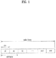
- FIG. 1 is a diagram for one example of a structure of a radio frame used by E-UMTS system.
- an E-UMTS system uses a radio frame of 10 ms. And, one radio frame includes 10 subframes. Each of the subframes includes 2 slots contiguous with each other. One slot may have a length of 0.5 ms and may be constructed with a plurality of symbols (e.g., OFDM (orthogonal frequency division multiplexing) symbols, SC-FDMA (single carrier frequency division multiple access) symbols).
- OFDM orthogonal frequency division multiplexing
- SC-FDMA single carrier frequency division multiple access
- FIG. 2 is a diagram for one example of a resource grid of a lot.
- a slot includes a plurality of OFDM symbols or SC-FDMA symbols and also includes a plurality of resource blocks (RBs) in frequency domain.
- resource block includes 12 ⁇ 6 or 12 ⁇ 7 resource elements (REs).
- the number N RB of RBs included in a time slot depends on a transmission bandwidth configured in a cell.
- Each box in the resource grid indicates a minimum resource defined by one symbol and one subcarrier, which is called a resource element (RE).
- FIG. 3 exemplarily shows that a time slot and a resource block include 7 symbols and 12 subcarriers, respectively, by which the present invention may be non-limited.
- the number of symbols included in a slot may be variable depending on a length of a cyclic prefix (hereinafter abbreviated CP).
- CP cyclic prefix
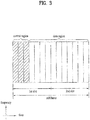
- FIG. 3 is a diagram for a structure of a DL subframe.
- L1/L2 control region and data region are multiplexed together by TDM (time division multiplexing).
- the L1/L2 control region is configured with 1 st n (e.g., 3, 4, etc.) OFDM symbols of a subframe and the rest of the OFDM symbols are used as the data region.
- the L1/L2 control region includes PDCCH (physical downlink control channel) configured to carry DL control information and the data region includes PDSCH (physical downlink shared channel) as a DL data channel.
- PDCCH physical downlink control channel
- PDSCH physical downlink shared channel
- a user equipment reads DL scheduling information from PDCCH and then receives DL data on PDSCH using resource allocation information indicated by the DL scheduling information.
- the resource (i.e., PDSCH) scheduled for the user equipment is allocated by a resource block unit or a resource block group unit.
- PDCCH informs a user equipment of information related to resource allocation of transport channels PCH (paging channel) and DL-SCH (downlink-shared channel), UL scheduling grant, HARQ information and the like.
- the information carried on PDCCH is commonly called control information (DCI).
- DCI control information
- control information there are various kinds of DCI formats.
- Table 1 shows DCI format 0 for UL scheduling.
- Field Bits Comment Format 1 Uplink grant or downlink assignment Hopping flag 1 Frequency hopping on/off RB assignment 7 a) Resource block assigned for PUSCH MCS 5 Modulation scheme, coding scheme, etc.
- New Data Indicator 1 Toggled for each new transport block TPC 2 Power control of PUSCH Cyclic shift for DMRS 3 Cyclic shift of demodulation reference signal CQI request 1 To request CQI feedback through PUSCH RNTI/CRC 16 16 bit RNTI implicitly encoded in CRC Padding 1 To ensure format 0 matches format 1A in size Total 38 - * MCS: Modulation and Coding Scheme * TPC: Transmit Power Control * RNTI: Radio Network Temporary Identifier) * CRC: Cyclic Redundancy Check
- PDCCH may be able to identify whether PDCCH s transmitted to a specific user equipment using RNTI. For instance, assume that PDCCH is CRC masked with RNTI named A and that the PDCCH carries UL resource allocation information B (e.g., frequency position) and transmission format information C (e.g., transport block size, modulation scheme, coding information, etc.).
- UL resource allocation information B e.g., frequency position
- transmission format information C e.g., transport block size, modulation scheme, coding information, etc.
- a user equipment in a cell monitors PDCCH using RNTI of its own and the user equipment having the RNTI A performs a UL transmission in accordance with the informations B and C obtained from the PDCCH.
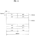
- FIG. 4 is a diagram for one example of a structure of a UL subframe used by LTE.
- a UL frame includes a plurality of slots (e.g., 2 slots). Each of the slots may include a different number of SC-FDMA symbols in accordance with a CP length.
- the UL subframe may be divided into a data region and a control region in frequency domain.
- the data region includes PUSCH and is used to transmit such a data signal as an audio and the like.
- the control region includes PUCCH and is used to transmit UL control information (UCI).
- the PUCCH includes an RB pair situated at both ends of the data region and performs hopping over the boundary of a slot.
- the UL control information includes SR (scheduling request) to request an uplink resource, HARQ ACK/NACK (hybrid automatic repeat and request acknowledgement/negative acknowledgement) for DL data packet, DL channel information and the like.
- SR scheduling request
- HARQ ACK/NACK hybrid automatic repeat and request acknowledgement/negative acknowledgement
- the DL channel information may include PMI (precoding matrix indicator), RI (rank indicator) and CQI (channel quality indicator).
- CQI Channel Quality Indicator
- CQI channel quality indicator
- the CQI may be created in various ways.
- the CQI may represent channel state information, and more particularly, CQI, PMI, RI or a combination thereof unless mentioned especially.
- the CQI may be created by one of a method of quantizing a channel state (or, spectrum efficiency) and then indicating the quantized channel state, a method of calculating SINR and then indicating the calculated SINR, a method of indicating a state of actually applying a channel like MCS (modulation and coding scheme) and the like.
- the CQI is crated on the basis of MCS.
- This method is described in detail as follows. First of all, there is a CQI creation for a transmission scheme such as HSPDA in 3GPP or the like. If the CAI is created on the basis of the MCS, since the MCS includes a modulation scheme, a coding scheme, a corresponding coding rate and the like, if the modulation scheme and/or the coding scheme changes, the CQI should change correspondingly. Hence, at least one CQI is necessary per codeword.
- Table 2 shows one example of a case of generating CQI by MCS.
- CQI index modulation code rate x 1024 Efficiency 0 out of range 1 QPSK 78 0.1523 2 QPSK 120 0.2344 3 QPSK 193 0.3770 4 QPSK 308 0.6016 5 QPSK 449 0.8770 6 QPSK 602 1.1758 7 16QAM 378 1.4766 8 16QAM 490 1.9141 9 16QAM 616 2.4063 10 64QAM 466 2.7305 11 64QAM 567 3.3223 12 64QAM 666 3.9023 13 64QAM 772 4.5234 14 64QAM 873 5.1152 15 64QAM 948 5.5547
- FIG. 5 is a conceptional diagram for one example of CQI creation and transmission.
- a wireless communication system may use link adaptation in order to use a given channel capacity to the maximum.
- the link adaptation adjusts MCS (modulation and coding scheme) and transmit power in accordance with a given channel.
- MCS modulation and coding scheme
- a user should feed back channel quality information to a base station eventually.
- a user equipment measures a DL quality and then reports a CQI value, which is selected based on the measured DL quality, to a base station on a UL control channel. Subsequently, the base station performs a DL scheduling (e.g., user equipment selection, resource allocation, etc.) in accordance with the reported CQI value.
- a DL scheduling e.g., user equipment selection, resource allocation, etc.
- the CQI value may include one of SINR (Signal to Interference and Noise Ratio), CINR (Carrier to Interference and Noise Ratio), BER (Bit Error Rate) and FER (Frame Error Rate) of a channel or a value resulting from converting one of SINR, CINR, BER and FER to a transmittable data.
- SINR Signal to Interference and Noise Ratio
- CINR Carrier to Interference and Noise Ratio
- BER Bit Error Rate
- FER Fre Error Rate
- RI Rank Information
- PMI Precoding Matrix Information
- Transport block error probability does not exceed 0.1 if a single PDSCH transport block is received via a resource block (CQI reference resource) related to a CQI index with a combination of a modulation scheme corresponding to the CQI index and a transport block size.
- CQI reference resource resource block
- a channel abruptly varies within the corresponding bandwidth.
- a multicarrier system e.g., OFDM system
- a modulated symbol is carried on each of the subcarriers
- it may be able to transmit a channel on each subcarrier.
- a feedback size of channel information may increase abruptly.
- various methods have been proposed.
- channel information may be transmitted by a subcarrier group unit instead of a subcarrier unit. If 12 subcarriers are combined together into one subcarrier group in OFDM system using 2,048 subcarriers, total 171 subcarrier groups are formed. Hence, a size of actually transmitted channel information is reduced down to 171 from 2,048.
- a basic unit for CQI creation is defined as CQI subcarrier group or CQI subband.
- a whole frequency band is divided into partial frequency bands and CQI can be then created with reference to the divided frequency band.
- the frequency band divided for the CQI creation is defined as a CQI subband.
- channel information it may be able to reduce an information size of a channel quality indicator.
- channel information of each subcarrier is compressed and transmitted.
- This compression scheme may include DCT (discrete cosine transform) for example.
- a frequency band e.g., CQI subband
- it may be able to reduce an information size of a channel quality indicator. For instance, instead of transmitting channel information on all subcarriers in OFDM scheme, it may be able to use a scheme (i.e., M scheme) of transmitting channel information by selecting M subcarriers or M subcarrier groups.
- M scheme M frequency bands having best channel quality are selected [Best-M scheme] or M frequency bands preferred by a base station and/or a user equipment are selected according to a prescribed reason [Preferred-M scheme].
- the preferred-M scheme may include the best-M scheme.
- the 1 st part is a CQI value part and the 2 nd part is a CQI index part.
- the best-M scheme is used as a representative example of the M scheme unless mentioned differently.
- FIG. 6 shows a method of generating CQI by selecting CQI subband from a frequency domain.
- Frequency band selective CQI scheme is mainly configured with 3 parts.
- a user equipment selects a frequency band (i.e., CQI subband) to create CQI.
- the user equipment creates and transmits CQI by manipulating channel information of the selected frequency bands.
- the user equipment transmits identification information (e.g., subband index) on the selected frequency band.
- identification information e.g., subband index
- the CQI subband selecting method includes a best-M scheme and a threshold-based scheme.
- the best-M scheme is a scheme of selecting M CQI subbands in good channel state.
- a user equipment selects CQI subbands of indexes #5, #6 and #9 using the best-3 scheme.
- CQI subband having a channel state higher than a threshold is selected.
- a user equipment selects CQI subbands of indexes # 5 and #6 each of which is higher than a threshold.
- the CQI value generating and transmitting method includes an individual scheme and an average scheme.
- the individual scheme is a scheme of transmitting all CQI values of selected CQI subbands.
- the average scheme transmits an average of CQI values of the selected CQI subbands.
- the average scheme it is advantageous in that only one CQI value is transmitted irrespective of the number of the selected CQI subbands.
- the average scheme transmits a CQI average value of several CQI subbands, it may have a reduced accuracy.
- the average value may include a simple arithmetic average or an average in consideration of channel capacity.
- the CQI subband index transmitting method includes a bitmap index scheme and a general combinatorial scheme.
- the bitmap index scheme 1 bit is assigned to each CQI subband. If the corresponding CQI subband is used, '1' is assigned to the corresponding bit. Otherwise, '0' is assigned to the corresponding bit. On the contrary, it may be able to set up a bit value.
- the bitmap index scheme needs the bit number amounting to total CQI subbands but may be able to always indicate CQI subbands via a predetermined number of bit(s) no matter how may CQI subbands are used.
- the combinatorial index scheme determines how may CQI subbands will be used is determined and then maps every combination of a predetermined number of CQI subbands selected from total CQI subbands to a corresponding index.
- f M CQI subband indexes are used among the N CQI subbands, a total number of possible combinations can be represented as Formula 1.
- C M N N ! N ⁇ 1 ! M !
- CQI increases the number f transmissions in various dimensions to cause more overhead.
- the former CQI mentioned in the above description corresponds to one frequency band only. If a receiving side notifies a CQI for a frequency band in a best channel state only and a transmitting side performs a service via the corresponding frequency band, CQI is necessary for one band only. Yet, since the above-described example is suitable for a single user environment but unsuitable for a multi-user environment, the demand for a more efficient method rises. A problem, which is caused in the course of scheduling in case of transmitting CQI on one preferred band only, is described in detail as follows. First of all, if frequency bands preferred by multiple users do not overlap with each other, there will be no problem.
- a CQI transmission size increases three times and an addition transmission for an indicator indicating a selected frequency band is required.
- a CQI information size e.g., the number of transmissions
- a CQI information size e.g., the number of transmissions
- several CQIs are necessary for the space dimension.
- it may consider a case that several CQIs are necessary for the frequency dimension as well.
- an increase of a CQI information size may be taken into consideration in other dimensions. For instance, if CDMA (code division multiple access) is used, a signal strength, an interference quantity and the like may fluctuate per spreading code, whereby CQI information is required for each spreading code. Hence, it may be able to consider an increase of a CQI information size (e.g., the number of transmissions) in code dimension. And, an increase of a CQI information size in one of various dimensions can be taken into consideration.
- CDMA code division multiple access
- a differential CQI (Delta CQI) to reduce a CQI transmission size.
- a reference CQI is normally transmitted but a difference from a reference CQI is transmitted for other CQIs.
- the greater number of bits is assigned to a CQI reference value but the relatively smaller number of bits is assigned to a differential value, whereby a total transmission size of transmitted CQIs can be reduced.
- Table 3 shows UL channel used for CQI transmission in LTE system.
- Table 3 Scheduling type Periodic CQI transmission Aperiodic CQI transmission Frequency non-selective PUCCH Frequency selective PUCCH PUSCH
- CQI may be aperiodically transmitted on PUCCH.
- Aperiodic PUSCH feedback scheme of CQI is performed in a manner that a base station notifies RB allocation for transmitting feedback information, modulation information and the like each time using UL grant control information like a normal UL data transmission.
- CQI may be transmitted on PUSCH individually or together with data information.
- a request field is set to 1 in DCI format 0, a user equipment transmits CQI to a base station using an allocated PUSCH resource. Meanwhile, if field values of DCI format 0 meet prescribed conditions, a CQI request-only condition is met.
- Table 5 shows a mode in transmitting CQI on PUSCH.
- a mode shown in Table 5 is selected by a higher layer and all CQIs are transmitted in the same PUSCH subframe.
- PMI Feedback Type No PMI Single PMI Multiple PMI PUSCH CQI feedback type Wideband (wideband CQI) Mode 1-2 UE Selected (subband CQI) Mode 2-0 Mode 2-2 Higher Layer-configured (subband CQI) Mode 3-0 Mode 3-1
- CQI is periodically transmitted on PUCCH. Yet, if there is a PUSCH transmission at the timing point of transmitting CQI periodically, the CQI may be transmitted on PUSCH.
- Table 6 shows a mode in transmitting CQI periodically. A user equipment creates and transmits CQI by one of the schemes in the modes defined in Table 6. [Table 6] PMI Feedback Type No PMI Single PMI PUCCH CQI Feedback Type Wideband (wideband CQI) Mode 1-0 Mode 1-1 UE Selected (subband CQI) Mode 2-0 Mode 2-1
- RI and wideband CQI/PMI When RI and wideband CQI/PMI are transmitted, they are transmitted in subframes differing from each other in periodicity and offset. If RI and CQI/PMI need to be transmitted in the same frame, the CQI/PMI may not be transmitted.
- a user equipment performs a transmission in a manner of raising a power by UL transmit power control (TPC) if a channel environment of a base station is not good. If the channel environment is good, the user equipment performs a transmission in a manner of lowering a power. For instance, if the channel environment is not good, the base station gives the user equipment a TPC command for raising a transmit power. If the channel environment is good, the base station gives the user equipment a TPC command for lowering a transmit power.
- TPC transmit power control
- the UL transmission scheme in LTE is characterized in a single carrier property using SC-FDMA.
- SC-FDMA maintains PAPR (peak to average ratio) lower than that of OFDM, thereby enabling a power amplifier to be efficiently used.
- PUSCH, PUCCH and SRS (sounding reference signal) for UL channel measurement are not allowed to be simultaneously transmitted.
- information supposed to e transmitted on PUCCH is multiplexed with data by piggyback in PUSCH region.
- SC-FDMA symbol for carrying the SRS is configured not to carry PUSCH or PUCCH. Power controls of PUSCH and PUCCH are independently performed.
- UL ACK/NACK which is primary information in uplink, is a response to a DL data reception.
- a resource for UL ACK/NACK transmission is linked to a resource used for DL scheduling. Therefore, a PUCCH power control signal including ACK/NACK is transmitted to a user equipment in a manner of being included in a DL control signal indicating DL scheduling information.
- a PUSCH power control signal is transmitted to a user equipment in a manner of being included in a DL control signal delivering scheduling information on PUSCH.
- Scheduling for UL transmission in LTE is enabled only if UL transmission timing of a user equipment is synchronized.
- a random access procedure is used for various usages. For instance, a random access procedure is performed in case of an initial network access, a handover, a data occurrence or the like.
- a user equipment may be able to obtain UL synchronization via the random access procedure. Once the UL synchronization is obtained, a base station may be able to allocate a resource for UL transmission to the corresponding user equipment.
- the random access procedure may be classified into a contention based procedure and a non-contention based procedure.
- FIG. 7 is a diagram for one example of a contention based random access procedure.
- a user equipment receives information on a random access from a base station via system information. Thereafter, if the random access is required, the user equipment transmits a random access preamble (or a message 1) to the base station [S710]. Once the base station receives the random access preamble from the user equipment, the base station sends a random access response message (or, a message 2) to the user equipment [S720].
- a DL scheduling information on the random access response message may be transmitted on L1/L2 control channel (PDCCH) by being CRC masked with RA-RNTI (random access-RNTI).
- the user equipment Having received the RA-RNTI masked DL scheduling signal, the user equipment receives the random access response message on PDSCH and may be then able to decode the received random access response message. Subsequently, the user equipment checks whether a random access response information indicated to the user equipment is included in the received random access response message. In doing so, a presence or non-presence of the random access response information indicated to the user equipment may be checked in a manner of checking whether RAID (random access preamble ID) for the preamble having transmitted by the user equipment is present or not.
- RAID random access preamble ID
- the random access response information may include a timing advance indicating a timing offset information for synchronization, a radio resource allocation information on a resource used in UL, a temporary identifier (e.g., T-RNTI) for user equipment (UE) identification and the like.
- the user equipment sends a UL message (or, a message 3) on UL SCH (uplink shared channel) in accordance with the radio resource allocation information included in the received random access response information [S730].
- the base station Having received the UL message from the user equipment in the step S730, the base station sends a contention resolution message (or, a message 4) to the user equipment [S740].
- FIG. 8 is a diagram for one example of a non-contention based random access procedure.
- a non-contention based random access procedure may be used in a handover procedure or may exist if requested by an order given by a base station.
- a basic procedure is as good as a contention based random access procedure.
- a user equipment receives assignment of a random access preamble (i.e., a dedicated random access preamble) for the user equipment only from a base station [S810].
- a dedicated random access preamble indication information (e.g., a preamble index) may be included in a handover command message or may be received on PDCCH.
- the user equipment transmits the dedicated random access preamble to the base station [S820]. Thereafter, the user equipment receives a random access response from the base station [S830] and the random access procedure is ended.
- DCI format 1A In order to indicate a non-contention based random access procedure with a PDCCH order, DCI format 1A is used. And, the DCI format 1A may be used for compact scheduling for one PDSCH codeword. The following information is transmitted using the DCI format 1A.
- the DCI format 1A may be used for a random access procedure according to a PDCCH order.
- CC 1 component carrier
- a TPC command information included in a control signal indicating a DL scheduling information or a CQI request information included in a control signal indicating a UL scheduling information may b recognized as a control information on a UL CC corresponding to a DL CC.
- FIG. 9 shows one example of a carrier aggregation (CA) communication system.
- LTE-A aggregates a plurality of UL/DL CCs (uplink/downlink component carriers) to support wider UL/DL bandwidth.
- CC component carrier
- the terminology 'component carrier (CC)' may be substituted with such an equivalent terminology as a carrier, a cell and the like.
- CCs may be configured adjacent to or non-adjacent from each other.
- a bandwidth of each of the CCs may be determined independently.
- a link between DL CC and UL CC may be configured symmetric between a corresponding pair.
- the DL CC/UL CC link may be configured in a manner of being fixed to a system. Alternatively, the DL CC/UL CC link may be configured semi-statically.
- the PDCCH may b transmitted via a control region of each DL CC.
- the PDCCH may be able to carry information for scheduling PDSCH belonging to the DL CC having the PDCCH belong thereto or information for scheduling PUSCH of the UL CC linked to the DL CC [self-carrier scheduling].
- the PDCCH may be able to carry information for scheduling PDSCH/PUSCH of DL/UL CC in a system irrespective of the DL CC having the PDCCH belong thereto or the UL CC linked to the corresponding DL CC [cross-carrier scheduling].
- the cross-carrier scheduling it may be able to recognize a DL/UL CC becoming a scheduling target using a carrier indicator (CI).
- CI carrier indicator
- CI information is carried on CIF (carrier indicator field) of DCI.
- control information may be configured to be transmitted or received on specific CC only.
- This specific CC may be named a primary CC (or, an anchor CC) and other CCS may be named secondary CCs.
- a TPC command/CQI request included in a control signal (PDCCH) indicating DL/UL scheduling information is a control information on an individual CC or information applied to all CCs or a CC group including a plurality of CCs at a time.
- the present embodiment proposes that one or more CIF values are additionally configured for at least one specific CC.
- one of CIF values configured for a specific CC may be used to assign a configuration command/information request signal for an individual CC and other CIF value may be used to assign configuration command/information request signals for a plurality of CCs.
- the configuration command/information request signal may include a TPC command/CQI request and the like.
- a plurality of CCs may become all CCs of a system, all the aggregated CCs, or a specific CC group.
- a plurality of CCs, to which the configuration command/information request signal will be applied may be different per each of the CC(s) having the CIF value additionally assigned thereto.
- the mapping between CIF value and CC index, and the CC having the CIF value additionally configured therefor may be identically configured in every user equipment [UE-common configuration] or may be configured differently in each user equipment or each user equipment group [UE-specific configuration or UE group-specific configuration].
- FIG. 10 is a diagram for one example of assigning a configuration command/information request signal according to one embodiment of the present invention.
- CCs may be configured adjacent to or non-adjacent from each other.
- a bandwidth of each of the CCs may be determined independently.
- CIF values i.e., 0 ⁇ 4 (ObOO0, ObOO1, ObO10, ObO11)
- CC A CC E in sequence
- CIF value 0 ⁇ 4
- a TPC command or a CQI request may be recognized as a command for an individual CC.
- a TPC command or a CQI request is recognized as a command for a plurality of CCs (e.g., all CCs).
- a configuration command/information request for an individual CC it may be necessary to assign a CIF value per each CC.
- a configuration command/information request for a plurality of CCs e.g., all CCs
- a configuration command/information request for a plurality of CCs (e.g., all CCs) is transmitted together with scheduling information on a specific CC frequently allocated to a user equipment, it may be able to raise field configuration efficiency of a control signal for a signal delivery.
- a TCP command/CQI request for all CCs is assigned to only one of the remaining states.
- CC may be designated by the configuration command as follows.
- the indication of UL CC via CI may mean that a CI value directly indicates an index of UL CC.
- the indication of UL CC via CI may mean that a CI value firstly indicates an index of DL CC and that UL CC corresponding to the DL CC is then indicated.
- CQI carried on UL CC may commonly agreed as channel information on DL CC corresponding to (i.e., linked to) the UL CC by a base station and a user equipment.
- a DL CC which is not configured with a linkage to UL CC for any reason(s).
- such a DL CC may be called a DL CC having not corresponding UL CC or a non-linked DL CC. For instance, if the number of DL CCs is greater than that of UL CCs, it may be unable to define a 1-to-1 linkage between UL CC and DL CC for all DL CCs.
- the non-linked DL CC may be generated by a DL/UL CC set configuration assigned by RRC (radio resource control) signaling for a cell deployment or a specific user equipment.
- RRC radio resource control
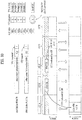
- FIG. 11 shows one example of transmitting CQI aperiodically.
- a user equipment receives a control channel containing channel quality information request.
- the channel quality information request may include a CQI request and the control channel may include PDCCH.
- the channel quality information request may be included in DCI format 0 [S1110].
- the user equipment then generates channel quality information for at least one specific DL carrier among a plurality of DL carriers (e.g., DL CCs) [S1120].
- the channel quality information may include CQI, PMI, RI or any one of combinations thereof.
- the user equipment transmits the generated channel quality information via a shared channel [S1130].
- the shared channel includes a PDSCH.
- the channel quality information may be transmitted with or without data.
- the specific DL carrier in the step S1120 is indicated using time information related to the channel quality information (or request).
- the time information related to the channel quality information may include time information on a time for a base station to transmit channel quality information request to a user equipment, time information on a time for a user equipment to receive channel quality information request from a base station or time information on a time for a user equipment to transmit the generated channel quality information to a base station.
- the time information related to the channel quality information is linked with a DL carrier for which the channel quality information is supposed to be reported. In this case, one time information may be linked with one DL carrier or a plurality of DL carriers.
- the user equipment may be able to determine DL CC, which becomes a CQI report target, using a subframe number (SN) for a base station to transmit a CQI request, a subframe number for receiving a CQI request command from a base station, a system frame number (SFN) corresponding to a corresponding subframe number, or a combination (SSN) of a corresponding subframe number and a system frame number (SFN).
- the user equipment may be able to determine DL CC, which becomes a CQI report target, using a subframe number, a system frame number, or a combination (SSN) of a subframe number and a system frame number for transmitting a CQI report.
- SSN may given as a form that contains 'A*SFN + B*SN' (where, A and B are integers equal o or greater than 0).
- the system frame number may be corresponding to a radio frame number.
- a user equipment when a user equipment aggregates total NC DL CCs, if a CQI request command is received, the user equipment may recognize DL CC, which is linked with an output value of Formula 3, as a CQI report target.
- modulo SN NC modulo SFN NC
- modulo SSN NC modulo SSN NC
- modulo(X, Y) is a function of returning a remainder resulting from dividing X by Y.
- NC, SN, SFN and SSN are same as defined in the forgoing description.
- a user equipment may be able to recognize DL CC, which has an output of Formula 3 as a CC index, as a CQI report target.
- the user equipment may be able to recognize DL CC, which has a CC index corresponding to a value obtained using an output value of Formula 3, as a CQI report target.
- the DL CC index may be determined in advance by broadcast/RRC signaling and the like.
- This method may be applicable to all DL CCs irrespective of whether DL CC is configured to correspond to UL CC (i.e., whether DL CC is linked to UL CC in advance) or not.
- a DL CC set, to which the present method is applied includes all DL CCs assigned to a user equipment or a portion of DL CCs designated by higher layer signaling (e.g., RRC signaling, etc.) only.
- FIG. 12 shows one example of linking time information related to CQI (request) in the method shown in FIG. 11 to DL CC(s) of CQI report target.
- a CQI linkage may be configured to enable a CQI request command to be recognized as a CQI request command for a plurality of DL CCs.
- Formula 3 may be modified into the following formula. modulo SN , NC + N , modulo SFN , NC + N , or modulo SSN , NC + N
- modulo(X, Y) is a function of returning a remainder resulting from dividing X by Y.
- NC, SN, SFN and SSN are same as defined in the forgoing description.
- N is an integer equal to or greater than 0.
- an output value of modulo function has a value of 0 ⁇ (NC + N -1).
- the output value of 0 ⁇ (NC -1) e.g., 0, 1, 2) is used to recognize an individual DL CC as a CQI report target.
- an output value of NC ⁇ (NC + N -1) e.g., 3, 4) may be used to recognize a plurality of DL CCs as a CQI report target.
- a plurality of the DL CCs may include a full DL CC set, an aggregated DL CC set, and a non-linked DL CC set.
- Formula 3 may be modified into the following formula. modulo SN , NC ⁇ N , modulo SFN , NC ⁇ N , or modulo SSN , NC ⁇ N
- modulo(X, Y) is a function of returning a remainder resulting from dividing X by Y.
- NC, SN, SFN and SSN are same as defined in the forgoing description.
- N is an integer equal to or greater than 0.
- an output value of modulo function has a value of 0 ⁇ (NC - N -1). Since the number of output values is smaller than the number of aggregated carriers, a portion of the output values may be overlappedly mapped to a plurality of DL CCs. Hence, a portion of the output values (e.g., 1, 2, 3) is used to recognize an individual DL CC as a CQI report target. And, the rest of the output value (e.g., 0) may be used to recognize a plurality of DL CCs as a CQI report target.
- FIG. 11 and FIG. 12 show the time information related to CQI (request) to determine DL CC becoming a CQI report target, for clarity of the description of the invention.
- it may be able to determine DL CC becoming a CQI report target using another parameter related to carrier aggregation in addition.
- a DL CC index (CIF) for receiving a CQI request command or a UL CC index (CIF) for transmitting CQI may be used together.
- the corresponding DL CC index (CIF) or the corresponding UL CC index (CIF) may be used as an offset value.
- FIG. 13 shows another example of transmitting CQI aperiodically.
- a CQI request when received, it may be able to configure a CQI linkage so as to enable the CQI request to be recognized as a CQI request for a plurality of DL CCs. For instance, if DL CC #1/#2 is linked with UL CC #1/#2 and DL CC #3/#4/#5 is a non-linked DL CC, it may be able to configure a CQI linkage such that, in view of CQI transmission, the DL CC #3 and the DL CC #4/#5 are linked to the UL CC #1 and the UL CC #2, respectively.
- a user equipment needs to transmit CQI on UL CC #1 in response to a CQI request, the user equipment recognizes both of the DL CC #1 and the DL CC #3 as CQI report targets and then performs CQI feedback.
- the user equipment recognizes all the DL CCs #1, DL CC #4 and DL CC #5 as CQI report targets and then performs CQI feedback.
- the CQI linkage may be pre-determined in advance via broadcast/RRC signaling or the like.
- a plurality of DL CCs (for clarity, named a CQI CC set) having CQI request command applied thereto may include one non-linked DL CC, a portion of non-linked DL CCs, or all non-linked DL CCs.
- the present example corresponds to a case that two CQI CC sets are configured.
- a CQI request command may apply to all DL CCs in a CQI CC set [i.e., Case 1] or a portion of DL CCs in a CQI CC set [i.e., Case 2]. Case 2 may be performed using the former method described with reference to FIG. 10 and FIG. 11 , by which the example may be non-limited.
- FIG. 14 shows another example of transmitting CQI aperiodically.
- a plurality of CIF values respectively indicating different DL CC indexes may overlap to indicate the same UL CC index.
- this method if a plurality of CIF values in PDCCHs scheduling PUSCH to carry CQI are configured to indicate the same UL CC, it may be able to discriminate DL CCs, which become CQI report targets, using a plurality of different CIF values indicating the same UL CC. For instance, referring to FIG.
- Information on a CIF value having DL/UL CC indexes mapped thereto overlappedly may be defined through specific rule/function configured in advance between a base station and a user equipment or may be notified to a user equipment by a base station through RRC or L1/L2 signaling.
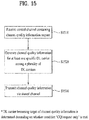
- FIG. 15 shows another example of transmitting CQI aperiodically.
- a user equipment receives a control channel containing channel quality information request.
- the channel quality information request may include a CQI request and the control channel may include PDCCH.
- the channel quality information request may be included in DCI format 0 [S1510].
- the user equipment then generates channel quality information on at least one specific DL carrier among a plurality of DL carriers (e.g., DL CCs) [S1520].
- the channel quality information may include CQI, PMI, RI or one of combinations thereof.
- the user equipment transmits the generated channel quality information via a shared channel [S1530].
- the shared channel includes a PDSCH.
- the channel quality information may be transmitted with or without data.
- DL carrier becoming a CQI report target is determined depending on whether a CQI request only condition is met.
- a CQI request only condition is met.
- a CQI request bit is set to 1
- a DL CC becoming a CQI report target may be differently indicated/recognized.
- a user equipment may be able to indicate/recognize that a CQI only for a DL CC linked to a UL CC, on which PUSCH will be transmitted, is reported.
- the user equipment may report CQI for all DL CCs assigned to the user equipment or may indicate/recognize that CQI for DL CC group previously designated to UL CC, which will carry PUSCH, is reported [Alt 1].
- condition 'CQI request only' may include a condition newly defined in LTE-A.
- the proposal Alt 1 may be more suitable for a case that an upper limit of N RB (or, upper and lower limits of N RB ) for the condition 'CQI request only' is defined relatively small.
- N RB (or, upper and lower limits of N RB ) for the condition 'CQI request only' is defined relatively large in LTE-A
- an operation opposite to the method Alt 1 may be more appropriate. For instance, if field value(s) configuring a UL PUSCH grant PDCCH (indicating a CQI request command) meets the condition 'CQI request only', it may be indicated/recognized that all CQIs for all DL CCs assigned to a user equipment or all CQIs for DL CC group previously designated to UL CC, on which PUSCH will be transmitted, are reported.
- a base station should independently adjust UL timing advance for each UL CC of the user equipment per UL CC. To this end, the base station should be able to give a command for RACH preamble transmission independently per UL CC using the former PDCCH order described with reference to FIG. 8 . Meanwhile, due to some reasons, limitation may be put on DL CC on which the PDCCH order for initiating a random access can be carried. This may correspond to an asymmetric carrier aggregation situation in which the number of UL CCs is greater than that of DL CCs.
- the PDCCH order for initiating a random access may be carried on specific DL CC (e.g., Primary CC) only due to such a reason as overhead reduction and the like.
- specific DL CC e.g., Primary CC
- the present embodiment proposes a method of configuring a CIF value, which is provided for a PDCCH order for performing an RACH preamble transmission command for UL CC, to directly indicate an index of UL CC on which a user equipment will transmit an RACH preamble. For instance, if an RACH preamble transmission command is transmitted using DCI format 1A, if each field in DCI format 1A is set to a PDCCH order for a random access, a user equipment may interpret a CIF value of the corresponding PDCCH as an index of UL CC on which an RACH preamble will be transmitted. Alternatively, it may be able to consider another method. Namely, a CIF value in PDCCH order is indicated by a DL CC index.
- a UL CC to carry an RACH preamble is interpreted as a UL CC corresponding to a corresponding DL CC.
- it may be able to use CIF values configured to have DL/UL CC indexes mapped duplicatively.
- FIG. 16 is a diagram for one example of a base station and a user equipment applicable to the present invention.
- a wireless communication system may include a base station (BS) 110 and a user equipment (UE) 120.
- BS base station
- UE user equipment
- DL a transmitter is a part of the bas station 110 and a receiver is a part of the user equipment 120.
- UL a transmitter is a part of the user equipment 120 and a receiver is a part of the base station 110.
- the base station 110 may include a processor 112, a memory 114 and a radio frequency (RF) unit 116.
- the processor 112 may be configured to implement the procedures and/or methods proposed by the present invention.
- the memory 114 is connected with the processor 112 to store various kinds informations related to operations of the processor 112.
- the RF unit 116 is connected with the processor 112 and then transmits and/or receives radio signals.
- the user equipment 120 may include a processor 122, a memory 124 and a radio frequency (RF) unit 126.
- the processor 122 may be configured to implement the procedures and/or methods proposed by the present invention.
- the memory 124 is connected with the processor 122 to store various kinds informations related to operations of the processor 122.
- the RF unit 126 is connected with the processor 122 and then transmits and/or receives radio signals.
- the base station 110 and/or the user equipment 120 may have a single antenna or multiple antennas.
- the user equipment 120 may further include at least one of a power management module, a battery, a display, a keypad, a SIM card (optional), a speaker and a microphone [not shown in the drawing].
- a specific operation explained as performed by a base station may be performed by an upper node of the base station in some cases.
- various operations performed for communication with a user equipment may be performed by a base station or other networks (e.g., relay, etc.) except the base station.
- 'base station' can be replaced by such a terminology as a fixed station, a Node B, an eNode B (eNB), an access point and the like.
- eNB eNode B
- eNB eNode B
- 'terminal' may be replaced by such a terminology as a user equipment (UE), a mobile station (MS), a mobile subscriber station (MSS)' and the like.
- Embodiments of the present invention may be implemented using various means. For instance, embodiments of the present invention may be implemented using hardware, firmware, software and/or any combinations thereof. In case of the implementation by hardware, one embodiment of the present invention may be implemented by one of ASICs (application specific integrated circuits), DSPs (digital signal processors), DSPDs (digital signal processing devices), PLDs (programmable logic devices), FPGAs (field programmable gate arrays), processor, controller, microcontroller, microprocessor and the like.
- ASICs application specific integrated circuits
- DSPs digital signal processors
- DSPDs digital signal processing devices
- PLDs programmable logic devices
- FPGAs field programmable gate arrays
- processor controller, microcontroller, microprocessor and the like.
- one embodiment of the present invention may be implemented by modules, procedures, and/or functions for performing the above-explained functions or operations.
- Software code may be stored in a memory unit and may be then drivable by a processor.
- the memory unit may be provided within or outside the processor to exchange data with the processor through the various means known to the public.
- the present invention is applicable to wireless access systems.
- the present invention is applicable to a method and apparatus for transmitting channel quality information in a wireless communication system.
Landscapes
- Engineering & Computer Science (AREA)
- Signal Processing (AREA)
- Computer Networks & Wireless Communication (AREA)
- Quality & Reliability (AREA)
- Mobile Radio Communication Systems (AREA)
Applications Claiming Priority (5)
| Application Number | Priority Date | Filing Date | Title |
|---|---|---|---|
| US31264010P | 2010-03-10 | 2010-03-10 | |
| US36785710P | 2010-07-26 | 2010-07-26 | |
| US37458810P | 2010-08-17 | 2010-08-17 | |
| US38430110P | 2010-09-19 | 2010-09-19 | |
| EP11753623.5A EP2547016A4 (fr) | 2010-03-10 | 2011-03-10 | Procédé et dispositif destinés à signaler des informations de commande dans un système d'agrégation de porteuses |
Related Parent Applications (1)
| Application Number | Title | Priority Date | Filing Date |
|---|---|---|---|
| EP11753623.5A Division EP2547016A4 (fr) | 2010-03-10 | 2011-03-10 | Procédé et dispositif destinés à signaler des informations de commande dans un système d'agrégation de porteuses |
Publications (1)
| Publication Number | Publication Date |
|---|---|
| EP3291476A1 true EP3291476A1 (fr) | 2018-03-07 |
Family
ID=44564011
Family Applications (2)
| Application Number | Title | Priority Date | Filing Date |
|---|---|---|---|
| EP17197534.5A Withdrawn EP3291476A1 (fr) | 2010-03-10 | 2011-03-10 | Procédé et dispositif de signalisation d'informations de commande dans un système basé sur une agrégation de porteuses |
| EP11753623.5A Withdrawn EP2547016A4 (fr) | 2010-03-10 | 2011-03-10 | Procédé et dispositif destinés à signaler des informations de commande dans un système d'agrégation de porteuses |
Family Applications After (1)
| Application Number | Title | Priority Date | Filing Date |
|---|---|---|---|
| EP11753623.5A Withdrawn EP2547016A4 (fr) | 2010-03-10 | 2011-03-10 | Procédé et dispositif destinés à signaler des informations de commande dans un système d'agrégation de porteuses |
Country Status (3)
| Country | Link |
|---|---|
| US (3) | US8917682B2 (fr) |
| EP (2) | EP3291476A1 (fr) |
| WO (1) | WO2011112018A2 (fr) |
Families Citing this family (31)
| Publication number | Priority date | Publication date | Assignee | Title |
|---|---|---|---|---|
| US8611313B2 (en) * | 2008-08-27 | 2013-12-17 | Qualcomm Incorporated | Multiplexing of control information and data for wireless communication |
| JP5301727B2 (ja) * | 2009-04-27 | 2013-09-25 | テレフオンアクチーボラゲット エル エム エリクソン(パブル) | キャリアアグリゲーションを用いる無線通信システムにおけるランダムアクセスのための資源割り当て方法及び装置 |
| JP5715124B2 (ja) * | 2009-06-25 | 2015-05-07 | コーニンクレッカ フィリップス エヌ ヴェ | モバイル・ネットワークにおいて通信する方法 |
| KR101650749B1 (ko) * | 2009-08-18 | 2016-08-24 | 삼성전자주식회사 | 릴레이를 위한 백홀 서브프레임의 제어 채널 자원 할당 방법 및 장치 |
| CN102215591B (zh) * | 2010-04-06 | 2013-12-04 | 华为技术有限公司 | 一种信道状态信息的传输方法及用户设备及基站 |
| US8891474B2 (en) | 2010-05-21 | 2014-11-18 | Sharp Kabushiki Kaisha | Mobile communication system, base station apparatus, mobile station apparatus and communication method |
| US9762372B2 (en) | 2010-06-15 | 2017-09-12 | Texas Instruments Incorporated | CSI reporting on PUSCH for carrier aggregation |
| WO2011162522A2 (fr) * | 2010-06-21 | 2011-12-29 | 엘지전자 주식회사 | Procédé et appareil de transmission d'informations d'état de canal |
| JP5559634B2 (ja) * | 2010-08-06 | 2014-07-23 | シャープ株式会社 | 基地局装置、移動局装置、移動通信システム、通信方法、制御プログラムおよび集積回路 |
| US9258092B2 (en) * | 2010-09-17 | 2016-02-09 | Blackberry Limited | Sounding reference signal transmission in carrier aggregation |
| CN103354478A (zh) * | 2011-03-31 | 2013-10-16 | 北京新岸线移动多媒体技术有限公司 | 一种用于实现链路自适应的方法、网络设备和终端设备 |
| KR20140044361A (ko) * | 2011-07-11 | 2014-04-14 | 엘지전자 주식회사 | 무선 통신 시스템에서 랜덤 액세스를 수행하는 방법 및 장치 |
| US9059822B2 (en) * | 2011-08-12 | 2015-06-16 | Telefonaktiebolaget L M Ericsson (Publ) | Radio network node, user equipment and methods therein |
| US9491738B2 (en) * | 2012-02-03 | 2016-11-08 | Qualcomm Incorporated | Managing downlink and uplink resources for low cost user equipments |
| EP2995019B1 (fr) * | 2013-05-09 | 2019-01-30 | Intel IP Corporation | Communications de petites données |
| US9414384B2 (en) | 2013-09-17 | 2016-08-09 | Telefonaktiebolaget Lm Ericsson (Publ) | State-driven secondary cell activation and deactivation |
| EP3110218A4 (fr) * | 2014-03-21 | 2017-03-01 | Huawei Technologies Co., Ltd. | Procédé permettant de transmettre des informations de données, station de base et équipement utilisateur |
| US9590764B2 (en) | 2014-09-15 | 2017-03-07 | Texas Instruments Incorporated | LTE transmission mask adjustment to maximize performance and reduce interference |
| CN105991263B (zh) * | 2015-01-30 | 2020-05-12 | 中兴通讯股份有限公司 | 下行控制信息dci的配置、下行数据的接收方法及装置 |
| CN106304380B (zh) * | 2015-06-26 | 2021-04-06 | 中兴通讯股份有限公司 | 一种资源调度的指示方法及装置 |
| WO2017044143A1 (fr) * | 2015-09-11 | 2017-03-16 | Intel IP Corporation | Accès de réseau radio de dispositifs pouvant être portés |
| JP6751099B2 (ja) * | 2015-10-29 | 2020-09-02 | シャープ株式会社 | 端末装置、基地局装置、および、通信方法 |
| US10869302B2 (en) * | 2015-11-16 | 2020-12-15 | Qualcomm Incorporated | Techniques for downlink assignment index (DAI) management in carrier aggregation |
| US10887941B2 (en) * | 2016-08-18 | 2021-01-05 | Qualcomm Incorporated | Retaining access to a shared radio frequency spectrum band during an uplink control portion of a transmission structure |
| CN110120859B (zh) * | 2018-02-05 | 2021-09-24 | 上海朗帛通信技术有限公司 | 一种被用于无线通信的用户设备、基站中的方法和装置 |
| US11290244B2 (en) | 2018-02-13 | 2022-03-29 | Sharp Kabushiki Kaisha | User equipments, base stations and methods |
| JP2019198014A (ja) * | 2018-05-10 | 2019-11-14 | シャープ株式会社 | 端末装置、基地局装置、および、通信方法 |
| US10820340B2 (en) | 2018-06-22 | 2020-10-27 | At&T Intellectual Property I, L.P. | Facilitation of frequency selective scheduling for 5G or other next generation network |
| US20220046701A1 (en) * | 2018-11-08 | 2022-02-10 | Lenovo (Beijing) Limited | Method and apparatus for control channel design for data transmission on unlicensed spectrum |
| CN111436059B (zh) * | 2019-02-14 | 2022-12-27 | 维沃移动通信有限公司 | 终端测量的处理方法和终端 |
| US11677531B2 (en) * | 2021-07-22 | 2023-06-13 | Qualcomm Incorporated | Channel quality indicator reporting across multiple subbands |
Citations (1)
| Publication number | Priority date | Publication date | Assignee | Title |
|---|---|---|---|---|
| EP2536203A1 (fr) * | 2010-02-11 | 2012-12-19 | China Academy of Telecommunications Technology | Procédé, système et dispositif pour la programmation d'un accès aléatoire non concurrentiel et pour la transmission d'un préambule |
Family Cites Families (14)
| Publication number | Priority date | Publication date | Assignee | Title |
|---|---|---|---|---|
| US6990324B2 (en) | 2004-04-15 | 2006-01-24 | Flarion Technologies, Inc. | Methods and apparatus for selecting between multiple carriers using a single receiver chain tuned to a single carrier |
| KR20050119590A (ko) * | 2004-06-16 | 2005-12-21 | 삼성전자주식회사 | 직교 주파수 분할 다중 방식을 사용하는 통신 시스템에서채널 품질 정보 피드백 장치 및 방법 |
| GB0500416D0 (en) * | 2005-01-10 | 2005-02-16 | Nokia Corp | Transmitting information using multiple carriers |
| KR20070027844A (ko) * | 2005-08-29 | 2007-03-12 | 삼성전자주식회사 | 무선통신 시스템에서 채널품질 정보를 전송하기 위한 방법및 장치 |
| US20070086371A1 (en) * | 2005-10-17 | 2007-04-19 | Telefonaktiebolaget Lm Ericsson | Controlled multi-user packet detection for a wireless packet data channel |
| US8649333B2 (en) * | 2006-03-20 | 2014-02-11 | Panasonic Corporation | Radio communication system, radio transmission apparatus, and resource allocation method |
| JP5283615B2 (ja) * | 2007-03-01 | 2013-09-04 | 株式会社エヌ・ティ・ティ・ドコモ | 基地局装置及び通信制御方法 |
| US9380503B2 (en) * | 2007-04-30 | 2016-06-28 | Google Technology Holdings LLC | Method and apparatus for handover in a wireless communication system |
| EP2196037A4 (fr) * | 2007-08-23 | 2012-01-25 | Ericsson Telefon Ab L M | Procédé pour une sélection d'accès contrôlé à un réseau |
| EA019570B1 (ru) * | 2007-10-24 | 2014-04-30 | Хуавэй Текнолоджиз Ко., Лтд. | Система мобильной связи, устройство базовой станции, устройство мобильной станции и способ мобильной связи |
| WO2010025360A2 (fr) * | 2008-08-29 | 2010-03-04 | Interdigital Patent Holdings, Inc. | Procédé et dispositif d’envoi de signal en retour pour un service partagé de liaison descendante et d’estimation du nombre d’unités d’émission/réception sans fil |
| US8934417B2 (en) * | 2009-03-16 | 2015-01-13 | Google Technology Holdings LLC | Resource allocation in wireless communication systems |
| EP2282575A1 (fr) * | 2009-08-04 | 2011-02-09 | Panasonic Corporation | Rapport de qualité de canal dans un système de communication mobile |
| JP5322832B2 (ja) * | 2009-08-06 | 2013-10-23 | シャープ株式会社 | 移動局装置、基地局装置、無線通信システムおよびランダムアクセス方法 |
-
2011
- 2011-03-10 EP EP17197534.5A patent/EP3291476A1/fr not_active Withdrawn
- 2011-03-10 EP EP11753623.5A patent/EP2547016A4/fr not_active Withdrawn
- 2011-03-10 US US13/583,448 patent/US8917682B2/en active Active
- 2011-03-10 WO PCT/KR2011/001673 patent/WO2011112018A2/fr active Application Filing
-
2014
- 2014-11-17 US US14/543,525 patent/US9516613B2/en active Active
-
2016
- 2016-11-09 US US15/347,367 patent/US9942891B2/en active Active
Patent Citations (1)
| Publication number | Priority date | Publication date | Assignee | Title |
|---|---|---|---|---|
| EP2536203A1 (fr) * | 2010-02-11 | 2012-12-19 | China Academy of Telecommunications Technology | Procédé, système et dispositif pour la programmation d'un accès aléatoire non concurrentiel et pour la transmission d'un préambule |
Non-Patent Citations (3)
| Title |
|---|
| "LTE; Evolved Universal Terrestrial Radio Access (E-UTRA); Physical layer procedures (3GPP TS 36.213 version 8.7.0 Release 8)", TECHNICAL SPECIFICATION, EUROPEAN TELECOMMUNICATIONS STANDARDS INSTITUTE (ETSI), no. V8.7.0, 1 June 2009 (2009-06-01), XP014044750 * |
| HUAWEI: "Multiple Timing Advance Impact on RAN2", 3GPP DRAFT; R2-100110, vol. RAN WG2, no. Valencia, Spain; 20100118, 12 January 2010 (2010-01-12), XP050420934 * |
| ZTE: "On DL Component Carrier Ambiguity in Initial Random Access Procedure", 3GPP DRAFT; R2-100312, vol. RAN WG2, no. Valencia, Spain; 20100118, 12 January 2010 (2010-01-12), XP050421017 * |
Also Published As
| Publication number | Publication date |
|---|---|
| US20120327883A1 (en) | 2012-12-27 |
| US9942891B2 (en) | 2018-04-10 |
| WO2011112018A2 (fr) | 2011-09-15 |
| US20150071232A1 (en) | 2015-03-12 |
| EP2547016A2 (fr) | 2013-01-16 |
| EP2547016A4 (fr) | 2017-05-17 |
| US9516613B2 (en) | 2016-12-06 |
| WO2011112018A3 (fr) | 2012-02-23 |
| US20170064677A1 (en) | 2017-03-02 |
| US8917682B2 (en) | 2014-12-23 |
Similar Documents
| Publication | Publication Date | Title |
|---|---|---|
| US9942891B2 (en) | Method and device for signaling control information in carrier aggregation system | |
| US10051613B2 (en) | Method for transmitting channel state information in wireless access system | |
| KR101369034B1 (ko) | 무선 통신 시스템에서 채널 품질 보고 방법 및 장치 | |
| US10701638B2 (en) | Method and apparatus for reducing energy consumption of terminal in wireless communication system | |
| US9544882B2 (en) | Method and apparatus for transmitting channel status information in carrier aggregation system | |
| US11882550B2 (en) | Method and apparatus for defining basic resource unit for NB-IoT user equipment in wireless communication system | |
| EP4050811A1 (fr) | Procédé et appareil pour la configuration d'un faisceau par défaut pour la communication coopérative en réseau | |
| US20140044085A1 (en) | Apparatus and method for transmitting resource allocation information | |
| US9036485B2 (en) | Method and apparatus for performing client cooperation transmission through a group resource allocation scheme in a wireless access system | |
| US11202305B2 (en) | Method and apparatus for transmission and reception of data channel in wireless communication system | |
| CN103109484A (zh) | 用于在无线通信系统中发送多个接收应答信息的方法和设备 | |
| US11540254B2 (en) | Apparatus and method for allocating resources in wireless communication system | |
| CN115866783A (zh) | 上行控制信息传输方法及装置 | |
| US11723042B2 (en) | Method and apparatus for uplink data channel with dropping operation in wireless communication system | |
| US20230318761A1 (en) | Method and device for transmitting/receiving control information in wireless cooperative communication system | |
| US20240306150A1 (en) | Apparatus and method for transmitting and receiving control information in communication system | |
| EP3831144B1 (fr) | Appareil et procédé d'attribution de ressources dans un système de communication sans fil |
Legal Events
| Date | Code | Title | Description |
|---|---|---|---|
| PUAI | Public reference made under article 153(3) epc to a published international application that has entered the european phase |
Free format text: ORIGINAL CODE: 0009012 |
|
| STAA | Information on the status of an ep patent application or granted ep patent |
Free format text: STATUS: REQUEST FOR EXAMINATION WAS MADE |
|
| 17P | Request for examination filed |
Effective date: 20171020 |
|
| AC | Divisional application: reference to earlier application |
Ref document number: 2547016 Country of ref document: EP Kind code of ref document: P |
|
| AK | Designated contracting states |
Kind code of ref document: A1 Designated state(s): AL AT BE BG CH CY CZ DE DK EE ES FI FR GB GR HR HU IE IS IT LI LT LU LV MC MK MT NL NO PL PT RO RS SE SI SK SM TR |
|
| STAA | Information on the status of an ep patent application or granted ep patent |
Free format text: STATUS: THE APPLICATION IS DEEMED TO BE WITHDRAWN |
|
| 18D | Application deemed to be withdrawn |
Effective date: 20180908 |