EP3291405B1 - Phase shifted full bridge charger control system and control method - Google Patents
Phase shifted full bridge charger control system and control method Download PDFInfo
- Publication number
- EP3291405B1 EP3291405B1 EP16892379.5A EP16892379A EP3291405B1 EP 3291405 B1 EP3291405 B1 EP 3291405B1 EP 16892379 A EP16892379 A EP 16892379A EP 3291405 B1 EP3291405 B1 EP 3291405B1
- Authority
- EP
- European Patent Office
- Prior art keywords
- charger
- current
- ref
- limiting
- charging
- Prior art date
- Legal status (The legal status is an assumption and is not a legal conclusion. Google has not performed a legal analysis and makes no representation as to the accuracy of the status listed.)
- Active
Links
Images


Classifications
-
- H—ELECTRICITY
- H01—ELECTRIC ELEMENTS
- H01M—PROCESSES OR MEANS, e.g. BATTERIES, FOR THE DIRECT CONVERSION OF CHEMICAL ENERGY INTO ELECTRICAL ENERGY
- H01M10/00—Secondary cells; Manufacture thereof
- H01M10/42—Methods or arrangements for servicing or maintenance of secondary cells or secondary half-cells
- H01M10/44—Methods for charging or discharging
-
- H—ELECTRICITY
- H02—GENERATION; CONVERSION OR DISTRIBUTION OF ELECTRIC POWER
- H02J—ELECTRIC POWER NETWORKS; CIRCUIT ARRANGEMENTS OR SYSTEMS FOR SUPPLYING OR DISTRIBUTING ELECTRIC POWER; SYSTEMS FOR STORING ELECTRIC ENERGY
- H02J7/00—Circuit arrangements for charging or discharging batteries or for supplying loads from batteries
-
- H—ELECTRICITY
- H02—GENERATION; CONVERSION OR DISTRIBUTION OF ELECTRIC POWER
- H02J—ELECTRIC POWER NETWORKS; CIRCUIT ARRANGEMENTS OR SYSTEMS FOR SUPPLYING OR DISTRIBUTING ELECTRIC POWER; SYSTEMS FOR STORING ELECTRIC ENERGY
- H02J7/00—Circuit arrangements for charging or discharging batteries or for supplying loads from batteries
- H02J7/02—Circuit arrangements for charging or discharging batteries or for supplying loads from batteries for charging batteries from AC mains by converters
-
- H—ELECTRICITY
- H02—GENERATION; CONVERSION OR DISTRIBUTION OF ELECTRIC POWER
- H02J—ELECTRIC POWER NETWORKS; CIRCUIT ARRANGEMENTS OR SYSTEMS FOR SUPPLYING OR DISTRIBUTING ELECTRIC POWER; SYSTEMS FOR STORING ELECTRIC ENERGY
- H02J7/00—Circuit arrangements for charging or discharging batteries or for supplying loads from batteries
- H02J7/90—Regulation of charging or discharging current or voltage
-
- H—ELECTRICITY
- H02—GENERATION; CONVERSION OR DISTRIBUTION OF ELECTRIC POWER
- H02M—APPARATUS FOR CONVERSION BETWEEN AC AND AC, BETWEEN AC AND DC, OR BETWEEN DC AND DC, AND FOR USE WITH MAINS OR SIMILAR POWER SUPPLY SYSTEMS; CONVERSION OF DC OR AC INPUT POWER INTO SURGE OUTPUT POWER; CONTROL OR REGULATION THEREOF
- H02M1/00—Details of apparatus for conversion
- H02M1/36—Means for starting or stopping converters
-
- H—ELECTRICITY
- H02—GENERATION; CONVERSION OR DISTRIBUTION OF ELECTRIC POWER
- H02J—ELECTRIC POWER NETWORKS; CIRCUIT ARRANGEMENTS OR SYSTEMS FOR SUPPLYING OR DISTRIBUTING ELECTRIC POWER; SYSTEMS FOR STORING ELECTRIC ENERGY
- H02J7/00—Circuit arrangements for charging or discharging batteries or for supplying loads from batteries
- H02J7/60—Circuit arrangements for charging or discharging batteries or for supplying loads from batteries including safety or protection arrangements
- H02J7/62—Circuit arrangements for charging or discharging batteries or for supplying loads from batteries including safety or protection arrangements against overcurrent
-
- Y—GENERAL TAGGING OF NEW TECHNOLOGICAL DEVELOPMENTS; GENERAL TAGGING OF CROSS-SECTIONAL TECHNOLOGIES SPANNING OVER SEVERAL SECTIONS OF THE IPC; TECHNICAL SUBJECTS COVERED BY FORMER USPC CROSS-REFERENCE ART COLLECTIONS [XRACs] AND DIGESTS
- Y02—TECHNOLOGIES OR APPLICATIONS FOR MITIGATION OR ADAPTATION AGAINST CLIMATE CHANGE
- Y02E—REDUCTION OF GREENHOUSE GAS [GHG] EMISSIONS, RELATED TO ENERGY GENERATION, TRANSMISSION OR DISTRIBUTION
- Y02E60/00—Enabling technologies; Technologies with a potential or indirect contribution to GHG emissions mitigation
- Y02E60/10—Energy storage using batteries
Definitions
- the present invention belongs to the technical field of control to chargers, and relates to a control method for a phase shifted full bridge charger having multiple running modes.
- Train chargers are used to supply power to all the DC loads in the train and charge storage batteries.
- a charger has multiple running modes, specifically including a constant-voltage mode, a charging-current-limiting mode and a total-current-limiting mode.
- each running mode corresponds to different control strategies, that is, a constant-voltage control strategy, a charging-current-limiting control strategy and a total-current-limiting control strategy.
- a phase shifted full bridge (PSFB) charger is a charger in which a PSFB converter is used as a soft switch of the charger.
- the structure of the PSFB charger includes a PSFB circuit, a high frequency transformer and a rectifying circuit, which are connected successively, wherein the PSFB circuit includes a support capacitor and a charging resistor; and an output terminal of the rectifying circuit is connected to the storage battery and loads, respectively, to charge the storage battery and drive the loads to run.
- the PSFB charger When a train is operating, the PSFB charger is also to be frequently switched between the three running modes.
- a control system of the PSFB charger has to respond to the switchover between the running modes in time, so as to perform switchover between the three control strategies in time.
- the three control strategies are under PI (Proportional-Integral) control. If three groups of the same proportional parameters and integral parameters are used, the individuality of each running mode cannot be satisfied, and the technical requirements of controlling both the voltage and the current in a steady state cannot be fulfilled.
- Chinese patent publication CN 102 340 165 B discloses an electrodynamic force vehicle power supply management system.
- PCT publication WO 2008/103456 A1 discloses a pulsed plasma system with pulsed sample bias for etching semiconductor structures.
- Chinese patent publication CN 103 618 366 B discloses an intelligent ship charging machine.
- Chinese utility model publication CN 203 423 529 U discloses an intelligent car-mounted charger for a new energy automobile lithium battery.
- An objective of the present application is to provide a control method for smooth switchover between different operating modes of a PSFB charger according to the switchover operation state of a train charger in the prior art.
- a control method for a phase shifted full bridge charger is provided, the control method using a control system comprising a sampling system and a charger controller;
- the sampling system comprises an input voltage acquisition device mounted at an input terminal of a charger to acquire an input voltage, a total output voltage acquisition device and a total output current acquisition device both mounted at an output terminal of the charger to respectively acquire a total output voltage and a total output current, and a charging current acquisition device mounted at an input terminal of a storage battery to acquire a charging current.
- the charger controller comprises:
- the control method comprises the following steps:
- V out denotes the total output voltage value
- V out-ref denotes the total output voltage limiting value
- I out denotes the total output current value
- I out-ref denotes the total output current limiting value
- I bat denotes the charging current value
- I bat-ref denotes the charging current limiting value
- V ref denotes the reference value of the total output voltage.
- a support capacitor is provided at an input terminal of the PSFB circuit, and it is determined whether the pre-charging ends by determining the relation between a voltage on the support capacitor in the PSFB circuit of the charger and an input voltage of the charger.
- a method for determining whether the soft start of the charger ends is as follows: when condition 1 or condition 2 or condition 3 or condition 4 is fulfilled, it is determined that the soft start of the charger ends, wherein:
- V os 0.98 V ref
- I os 0.98 I out-ref
- I bs 0.98 I bat-ref .
- the present application has the following beneficial effects.
- the structure of the PSFB charger comprises a PSFB circuit, a high frequency transformer and a rectifying circuit, which are connected successively, wherein, an output terminal of the rectifying circuit is connected to a storage battery and loads, respectively, to charge the storage battery and drive the loads to run.
- chargers described in this implementation are all PSFB chargers.
- Fig. 2 shows a start flowchart of a PSFB charger in a normal operation.
- the following control system for a PSFB charger is designed.
- a control system for a PSFB charger comprises a sampling system and a charger controller; the sampling system comprises an input voltage acquisition device mounted at an input terminal of the charger to acquire an input voltage, a total output voltage acquisition device and a total output current acquisition device both mounted at an output terminal of the charger to respectively acquire a total output voltage and a total output current, and a charging current acquisition device mounted at an input terminal of a storage battery to acquire a charging current.
- current and voltage can be acquired by corresponding current sensors and voltage sensors, and corresponding current sampling circuits or voltage sampling circuits can also be designed, etc.
- the input voltage is an input voltage of the PSFB circuit
- the total output voltage is an output voltage of the full-wave rectifying circuit.
- the total output voltage is divided into two branches, with one branch used for driving loads and the other branch used for charging the storage battery.
- the charging current is the current charging the storage battery.
- the input voltage acquisition device is mounted at a front terminal of the PSFB circuit, i.e., the input terminal of the PSFB circuit, to sample the input voltage;
- the total output voltage acquisition device is mounted at the output terminal of the full-wave rectifying circuit to sample the total output voltage;
- the total current acquisition device is also mounted at the output terminal of the full-wave rectifying circuit to sample the total output current;
- the charging current sampling device is mounted at the input terminal of the storage battery to sample the charging current of the storage battery.
- the charger controller is a device comprehensively controlling the start and running of the charger, comprising the following units:
- the charger controller further comprises a smooth switchover control unit configured to receive the running state signal of the charger fed back by the mode determination unit and the soft start state signal fed back by the start and running determination unit.
- a smooth switchover control unit configured to receive the running state signal of the charger fed back by the mode determination unit and the soft start state signal fed back by the start and running determination unit.
- start and running determination unit might be the waiting state signal, the pre-charging state signal, the soft start state signal or the running state signal of the charger. Only when the signal fed back by the start and running determination unit to the smooth switchover control unit is the soft state signal and the running state signal, can the smooth switchover control unit operate. However, when the PSFB charger operates in the waiting state or the pre-charging state, the smooth switchover control unit will not operate.
- the charger controller when the charger is switched from the soft start mode to the constant-voltage running mode, the charger controller is smoothly switched to the constant-voltage control unit; and when the charger is switched from the constant-voltage running mode to the total-current-limiting running mode, the charger controller is switched from the constant-voltage control unit to the total-current-limiting control unit. Similarly, when the charger is switched between different running modes, the charger controller is smoothly switched to a control unit matched with the running mode.
- the charger control method comprises the following steps: An advance bridge arm and a lagging bridge arm of the PSFB circuit are controlled by a PWM wave having a duty ratio of 50%.
- the PWM wave of the lagging bridge arm is lagged from the advance bridge arm by (1-DUTY) circle; and during the running process, the PWM wave of the lagging bridge arm is lagged from the advance bridge arm by (1-DUTY) circle.
- DUTY is Duty0 during the soft start
- the DUTY is Duty1, or Duty2, or Duty3 during the running process.
- Duty0 is the value of the duty ratio calculated by a soft start control algorithm
- Duty1 is the value of the duty ratio calculated by a constant-voltage control algorithm
- Duty2 is the value of the duty ratio calculated by a total-current-limiting control algorithm
- Duty3 is the value of the duty ratio calculated by a charging-current-limiting control algorithm.
- the charger After the charger is started, the charger will be pre-charged first. It is determined whether the pre-charging of the charger ends; if so, the charger comes into the soft start state, and the operation of the charger is controlled by the soft start control unit.
- the specific algorithm used by the start and running determination unit to determine whether the pre-charging ends is as follows.
- the support capacitor is provided at the input terminal of the PSFB circuit, and it is determined whether the pre-charging ends by determining the relation between the voltage on the support capacitor at the front terminal of the PSFB circuit for the charger and the input voltage of the charger.
- R denotes a pre-charging resistor
- C denotes a support capacitor
- V 1 denotes an input DC voltage which can be obtained by sampling
- V 0 denotes an initial voltage (generally 0) on the support capacitor
- V t denotes a voltage (generally 0.9* V 1 ) on the support capacitor C when the pre-charging ends.
- the charger It is determined whether the soft start of the charger ends; if so, the charger comes into the running mode and the running control unit operates. At each moment of time, the charger can operate in only one running mode.
- the determining whether the soft start of the charger ends is according to the signal fed back by the start and running determination unit; and the method about determining whether the soft start of the charger ends by the start and running determination unit is as follows: when condition 1 or condition 2 or condition 3 or condition 4 is fulfilled, it is determined that the soft start of the charger ends, wherein:
- the running control unit controls the charger by the constant-voltage control unit by default.
- the constant-voltage control unit might not be matched with the running state of the charger, and the running state of the charger is to be determined by the mode determination unit in a next step to quickly make an adjustment of the control unit.
- the mode determination unit receives the total output voltage value, the total output current value and the charging current value; and the set value of the charging current, a total output current limiting value, a charging current limiting value, and the reference value of the total output voltage are configured for the mode determination unit.
- the running state of the charger is determined according to the above received values and the set and reference values, and an instruction for the running state of the charger is fed back to the smooth switchover control unit.
- the smooth switchover control unit defaults that the charger comes into the constant-voltage running state, to activate the constant-voltage control unit.
- the constant-voltage control algorithm is used, and the constant-voltage control unit operates, however,
- the charging-current-limiting control algorithm In the charging-current-limiting running state, the charging-current-limiting control algorithm is used, and the charging-current-limiting control unit operates, however, when V out V ref ⁇ I out I out ⁇ ref and V out V ref ⁇ I bat I bat ⁇ ref , the charger comes into the constant-voltage running state, the smooth switchover control unit controls the switchover to the constant-voltage control unit which operates to switch to the constant-voltage control algorithm; or otherwise, when I out I out ⁇ ref ⁇ V out V ref and I out I out ⁇ ref ⁇ I bat I bat ⁇ ref , the charger comes into the total-current-limiting running state, the smooth switchover control unit controls the switchover to the total-current-limiting control unit which operates to switch to the total-current-limiting control algorithm; or otherwise, the charger still operates in the charging-current-limiting running state; In the total-current-limiting running state, the total-current-limiting control algorithm is used, and the total-current-limiting control unit operates, however, when V out V ref
- V out denotes the total output voltage value
- I out denotes the total output current value
- I out-ref denotes the total output current limiting value
- I bat denotes the charging current value
- I bat-ref denotes the charging current limiting value
- V ref denotes the reference value of the total output voltage
- the constant-voltage control algorithm, the total-current-limiting control algorithm and the charging-current-limiting control algorithm are all adopt PI controller in which three groups of different PI parameters are used, and K p and K l parameters meeting requirements on controlling steady states are selected respectively.
- K p and K l parameters meeting requirements on controlling steady states are selected respectively.
- the selection of PI parameters is known in the prior art and will not be repeated here.
- the method for designing a PI controller is as follows.
- T in the above two formulas denotes the output sampling frequency.
- V out (k) denotes the current sampling value of the total output voltage of the charger.
- Control to the soft start of the charger is open-loop control.
- duty(t) denotes the real-time value of the duty ratio at t moment
- ⁇ duty denotes the variation value of the duty ratio
- V ref is less than the set value of the total output voltage which is a target value of the total output voltage (i.e., V out ) of the charger, wherein the reference value V ref of the voltage changes over time; if V ref is less than the set value, the V ref is accumulated in a fixed step size to gradually approximate the set value of V out , so that the total output voltage gradually approximates the set value; if not, the V ref is equal to the set value, and then constant-voltage control is performed.
- the output u(k) of the constant-voltage control unit at the moment of switchover is used as u(k-1) of the charging-current-limiting control unit, and the e(k) of the charging-current-limiting control unit in the first time is calculated; similarly, when the charger is switched from the constant-voltage running mode to the total-current-limiting running mode, the output u(k) of the constant-voltage control unit at the moment of switchover is used as u(k-1) of the total-current-limiting control unit, and the e(k) of the total-current-limiting control unit in the first time is calculated.
- the charger comes into the total-current-limiting running mode, and the total-current-limiting control is directly performed.
- the output u(k) of the total-current-limiting control unit is given to the charging-current-limiting control unit or the constant-voltage control unit as u(k-1) respectively, and the e(k) of the charging-current-limiting control unit or the e(k) of the constant-voltage control unit in the first time is calculated.
- the charger comes into the charging-current-limiting mode, and the charging-current-limiting control is directly performed.
- the output u(k) of the charging-current-limiting control unit is given to the total-current-limiting control unit or the constant-voltage control unit as u(k-1) respectively, and the e(k) of the total-current-limiting control unit or the e(k) of the constant-voltage control unit in the first time is calculated.
- Fig. 4 shows an output waveform diagram of the charger, when the charger is switched between the constant-voltage running state and the total-current-limiting running state.
- the set reference value V ref of the voltage is 120 V
- the total output voltage V out of the charger is 120 V
- the total output current I out is 30 A.
- T1 when the charger comes into the total-current-limiting running state from the constant-voltage running state, the total output voltage V out of the charger is 114 V, thus achieving smooth switchover between the output voltages.
- T2 when the charger is switched from the total-current-limiting running state to the constant-voltage running state, there is a quick and smooth response from the total output voltage without great fluctuation. This indicates that stable switchover between the control algorithms can be realized.
- Fig. 5 shows an output waveform diagram of the charger, when the charger operates after the soft start ends and comes into the charging-current-limiting running state.
- the set reference value V ref of the output voltage is 120 V
- the charging current limiting value I bat-ref is 54 A
- the total output voltage V out of the charger is 120 V
- the charging current I bat is 30 A.
- the total output voltage V out of the charger is 116 V
- I bat is 54 A
- smooth switchover between the output voltages can be achieved. This indicates that, by the control system for the charger, stable switchover between the running states is realized and the amount of overshoot is controlled.
- Fig. 6 shows an output waveform diagram of the charger, when the charger is switched from the charging-current-limiting running state to the constant-voltage running state.
- the set reference value V ref of the output voltage is 120 V
- the total output voltage V out of the charger is 119 V
- the charging current limiting value I bat-ref is 54 A
- the charging current I bat is 54 A.
- the charger is switched from the charging-current-limiting running state to the constant-voltage running state, the total output voltage V out of the charger is 120 V, thus achieving smooth switchover between the output voltages.
- the value of I bat gradually decreases.
- sampling data is selected by the following methods:
Landscapes
- Engineering & Computer Science (AREA)
- Power Engineering (AREA)
- Manufacturing & Machinery (AREA)
- Chemical & Material Sciences (AREA)
- Chemical Kinetics & Catalysis (AREA)
- Electrochemistry (AREA)
- General Chemical & Material Sciences (AREA)
- Charge And Discharge Circuits For Batteries Or The Like (AREA)
- Dc-Dc Converters (AREA)
Description
- The present invention belongs to the technical field of control to chargers, and relates to a control method for a phase shifted full bridge charger having multiple running modes.
- Train chargers are used to supply power to all the DC loads in the train and charge storage batteries. According to different operating conditions of a train, a charger has multiple running modes, specifically including a constant-voltage mode, a charging-current-limiting mode and a total-current-limiting mode. To ensure the stable operation of a charger, each running mode corresponds to different control strategies, that is, a constant-voltage control strategy, a charging-current-limiting control strategy and a total-current-limiting control strategy.
- A phase shifted full bridge (PSFB) charger is a charger in which a PSFB converter is used as a soft switch of the charger. The structure of the PSFB charger includes a PSFB circuit, a high frequency transformer and a rectifying circuit, which are connected successively, wherein the PSFB circuit includes a support capacitor and a charging resistor; and an output terminal of the rectifying circuit is connected to the storage battery and loads, respectively, to charge the storage battery and drive the loads to run.
- When a train is operating, the PSFB charger is also to be frequently switched between the three running modes. Correspondingly, a control system of the PSFB charger has to respond to the switchover between the running modes in time, so as to perform switchover between the three control strategies in time. Generally, the three control strategies are under PI (Proportional-Integral) control. If three groups of the same proportional parameters and integral parameters are used, the individuality of each running mode cannot be satisfied, and the technical requirements of controlling both the voltage and the current in a steady state cannot be fulfilled. If three groups of different proportional parameters and integral parameters are used, at the moment of switchover between two control strategies, the proportional parameters and the integral parameters are to be switched quickly, thus leading to overshoot in voltage and current when the system is dynamically adjusted, or even damage in extreme situations.
- At present, there is no one control method that can ensure smooth switchover of a PSFB charger for a train between different running modes, and also stable operation of the PSFB charger at the moment of and after the switchover between different running modes.
- Chinese patent publication
CN 102 340 165 B discloses an electrodynamic force vehicle power supply management system. -
PCT publication WO 2008/103456 A1 discloses a pulsed plasma system with pulsed sample bias for etching semiconductor structures. - Chinese patent publication
CN 103 618 366 B discloses an intelligent ship charging machine. - Chinese utility model publication
CN 203 423 529 U discloses an intelligent car-mounted charger for a new energy automobile lithium battery. - An objective of the present application is to provide a control method for smooth switchover between different operating modes of a PSFB charger according to the switchover operation state of a train charger in the prior art.
- For this purpose, the present application provides the following technical solution: a control method for a phase shifted full bridge charger is provided, the control method using a control system comprising a sampling system and a charger controller; the sampling system comprises an input voltage acquisition device mounted at an input terminal of a charger to acquire an input voltage, a total output voltage acquisition device and a total output current acquisition device both mounted at an output terminal of the charger to respectively acquire a total output voltage and a total output current, and a charging current acquisition device mounted at an input terminal of a storage battery to acquire a charging current.
- More specifically, the charger controller comprises:
- a start and running determination unit configured to receive a total output voltage signal, a total output current signal, a charging current signal and a duty ratio, and determine whether the charger operates in a waiting state, a pre-charging state, a soft start state or a running state, and generate a corresponding state signal; and the running state comprises a constant-voltage running state, a total-current-limiting running state and a charging-current-limiting running state;
- a soft start control unit configured to control the charger during the soft start state of the charger;
- a running control unit configured to control the charger in the running state of the charger and determine the running state of the charger;
- the running control unit comprises:
- a mode determination unit configured to receive a total output voltage value, a total output current value and a charging current value, to determine which running state the charger operates in, and to generate a running state signal of the charger;
- a constant-voltage control unit configured to control the charger when the charger operates in the constant-voltage running state;
- a total-current-limiting control unit configured to control the charger when the charger operates in the total-current-limiting running state;
- a charging-current-limiting control unit configured to control the charger when the charger operates in the charging-current-limiting running state;
- the charger controller further comprises a smooth switchover control unit configured to receive the running state signal of the charger fed back by the mode determination unit, and a soft start state signal fed back by the start and running determination unit; when the charger is switched between the soft start state and the running state and between different running states, the control system is smoothly switched to a control unit corresponding to the running state to control a PSFB circuit of the charger.
- The control method comprises the following steps:
- determining whether the pre-charging of the charger ends; if so, the charger comes into the soft start state, and the operation of the charger is controlled by the soft start control unit;
- determining whether the soft start of the charger ends; if so, the charger comes into the running state, the running control unit operates, and the smooth switchover control unit acquiesces in that a control is switched to the constant-voltage control unit;
- receiving, by the mode determination unit, the total output voltage value, the total output current value and the charging current value; and configuring, for the mode determination unit, a set value of the charging current, a total output current limiting value, a charging current limiting value, and a reference value of the total output voltage; determining the running state of the charger by the above received values and set values; and feeding an instruction for the running state of the charger back to the smooth switchover control unit;
- in the constant- voltage running state, a constant-voltage control algorithm is used, however,
- When


in the charging-current-limiting running state, a charging-current-limiting control algorithm is used, however,
when


in the total-current-limiting running state, a total-current-limiting control algorithm is used, however,
when


- In the above formulas, Vout denotes the total output voltage value, Vout-ref denotes the total output voltage limiting value, Iout denotes the total output current value, Iout-ref denotes the total output current limiting value, Ibat denotes the charging current value. Ibat-ref denotes the charging current limiting value, and Vref denotes the reference value of the total output voltage.
- Preferably, a support capacitor is provided at an input terminal of the PSFB circuit, and it is determined whether the pre-charging ends by determining the relation between a voltage on the support capacitor in the PSFB circuit of the charger and an input voltage of the charger.
- Preferably, a method for determining whether the soft start of the charger ends is as follows: when
condition 1 orcondition 2 or condition 3 or condition 4 is fulfilled, it is determined that the soft start of the charger ends, wherein: -
condition 1, when a cumulative duty ratio is greater than a set value of a duty ratio;
- condition 2: the total output voltage Vout is greater than a set value of the total output voltage Vos;
- condition 3: the total output current Iout is greater than a set value of the total output current Ios; and
- condition 4: the charging current Ibat is greater than a set value of the charging current Ibs.
- Preferably, Vos = 0.98Vref, Ios = 0.98Iout-ref, Ibs = 0.98Ibat-ref .
- Preferably, the constant-voltage control algorithm, the total-current-limiting control algorithm and the charging-current-limiting control algorithm are all PI control algorithm, with three different groups of PI parameters being used:

as for the constant-voltage control algorithm: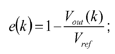
as for the total-current-limiting control algorithm:
as for the charging-current-limiting control algorithm:
when the soft start ends, the value of the current cumulative duty ratio DUTY is used as an input to the constant-voltage control unit, the total-current-limiting control unit and the charging-current-limiting control unit; wherein DUTY = duty(t) + Δduty. - The present application has the following beneficial effects.
- (1) The present application provides a control system and control method for a charger with multiple control units including a soft start control unit, a charging-current-limiting control unit, a total-current-limiting control unit and a constant-voltage control unit. Different control parameters are used in three control units to achieve the optimal stable effect in each running state or operation mode.
- (2) The controller of the present application further includes a smooth switchover control unit. When the charger is switched between different operation modes or running states, the smooth switchover of the control parameters (i.e., the control methods) between the control units can be achieved, with a small amount of overshoot and fast response time. Thus, good steady performance and dynamic performance are achieved.
-
-
Fig. 1 is a structure block diagram of the system; -
Fig. 2 is a flowchart of start and control of a charger; -
Fig. 3 is a flowchart of control by a controller; -
Fig. 4 is a waveform diagram of a total output voltage and a total output current of the charger, when the charger is switched between a constant-voltage running state and a total-current-limiting running state; -
Fig. 5 is a waveform diagram of a total output voltage and a total output current of the charger, when the charger comes into a charging-current-limiting running state after a soft start ends; and -
Fig. 6 is a waveform diagram of a total output voltage and a total output current of the charger, when the charger comes into a constant-voltage running state from a charging-current-limiting running state. - The specific implementations of the present application will be further described below in detail with reference to the accompanying drawings.
- As shown in
Fig. 1 , the structure of the PSFB charger comprises a PSFB circuit, a high frequency transformer and a rectifying circuit, which are connected successively, wherein, an output terminal of the rectifying circuit is connected to a storage battery and loads, respectively, to charge the storage battery and drive the loads to run. - It should be noted that the chargers described in this implementation are all PSFB chargers.
- The operating principle of a PSFB charger is as follows:
- 1. In the PSFB circuit for the charger, a voltage conversion is realized by a PSFB zero-voltage PWM (Pulse Width Modulation) converter, and a high DC voltage is input by the PSFB circuit to output a low DC voltage which is stable and adjustable.
- 2. A normal operating process of the charger is as follows: firstly, an input DC voltage is detected, and when the start condition is fulfilled, the support capacitor on the input side is pre-charged by a pre-charging resistor. The resistor is removed when the pre-charging of the support capacitor ends, and the soft start begins. During the soft start, a phase-shift angle is increased by a fixed duty ratio to increase the output voltage and current of the charger. When conditions are fulfilled, the charger comes into the running phase. Furthermore, according to the difference in the operating conditions of the charger, the switchover between modes and the running of the mode are realized by using different control strategies.
-
Fig. 2 shows a start flowchart of a PSFB charger in a normal operation. - 1. Waiting: an input DC voltage is detected, and the charger comes into a next stage when a minimum limiting value for start is reached;
- 2. Pre-charging: a pre-charging contactor is closed for a period of time (the pre-charging period), then a soft start contactor is closed; and the charger comes into a soft start stage;
- 3. Soft start: accumulation is performed by a fixed duty ratio so that a PWM wave having a certain phase-shift angle is output by the controller to control a power module; the output voltage and current are gradually increased; and when the operating conditions are fulfilled, the charger comes into a next stage;
- 4. Running state: comprising a constant-voltage running state, a charging-current-limiting running state and a total-current-limiting running state; the running mode of the charger is determined and then a corresponding PI controller is selected for closed-loop control.
- According to the operating principle and the start process of the PSFB charger, the following control system for a PSFB charger is designed.
- Still referring to
Fig. 1 , a control system for a PSFB charger comprises a sampling system and a charger controller; the sampling system comprises an input voltage acquisition device mounted at an input terminal of the charger to acquire an input voltage, a total output voltage acquisition device and a total output current acquisition device both mounted at an output terminal of the charger to respectively acquire a total output voltage and a total output current, and a charging current acquisition device mounted at an input terminal of a storage battery to acquire a charging current. With regard to the sampling system, current and voltage can be acquired by corresponding current sensors and voltage sensors, and corresponding current sampling circuits or voltage sampling circuits can also be designed, etc.. - Wherein, the input voltage is an input voltage of the PSFB circuit, and the total output voltage is an output voltage of the full-wave rectifying circuit. The total output voltage is divided into two branches, with one branch used for driving loads and the other branch used for charging the storage battery. The charging current is the current charging the storage battery.
- Specifically, the input voltage acquisition device is mounted at a front terminal of the PSFB circuit, i.e., the input terminal of the PSFB circuit, to sample the input voltage; the total output voltage acquisition device is mounted at the output terminal of the full-wave rectifying circuit to sample the total output voltage; the total current acquisition device is also mounted at the output terminal of the full-wave rectifying circuit to sample the total output current; and the charging current sampling device is mounted at the input terminal of the storage battery to sample the charging current of the storage battery.
- The charger controller is a device comprehensively controlling the start and running of the charger, comprising the following units:
- a start and running determination unit: configuring to receive a total output voltage signal, a total output current signal, a charging current signal and a duty ratio, and determine whether the charger operates in a waiting state, a pre-charging state, a soft start state or a running state, and generate a corresponding state signal, wherein the running state comprises a constant-voltage running state, a total-current-limiting running state and a charging-current-limiting running state; at the beginning of powering on the charger, the charger runs in the waiting state, and the start and running determination unit feeds back a waiting state signal; then the charger comes into the pre-charging state, and the start and running determination unit feeds back a pre-charging state signal; at the end of pre-charging, the charger comes into the soft start state, and the start and running determination unit feeds back a soft start state signal; then the charger comes into the running state; the soft start state signal is indicative of whether the charger still operates in the soft start mode or that the soft start is completed; regardless of the operation state of the charger, if the signal received by the start and running determination unit is indicative of a charger failure or indicates that the operating conditions do not fulfill the operation requirements, for example, overcurrent, overvoltage or the like, the charger comes back to the waiting state;
- a soft start control unit: configuring to control the charger during the soft start of the charger. Specifically, the soft start control unit will receive a signal from the start and running determination unit to determine whether the charger operates in the soft start state; and at the end of soft start, the charger will come into the running state;
- a running control unit: configuring to control the charger in the running state of the charger and determine different running modes of the charger,
- wherein, specifically, the running control unit comprises:
- a mode determination unit: configuring to receive a total output voltage value (the total output voltage signal), a total output current value (the total output current signal), and a charging current value (the charging current signal) to determine which running state the PSFB charger operates therein and generate a running state signal of the charger;
- a constant-voltage control unit: configuring to control the charger when the charger operates in the constant-voltage running state;
- a total-current-limiting control unit: configuring to control the charger when the charger operates in the total-current-limiting running state;
- a charging-current-limiting control unit: configuring to control the charger when the charger operates in the charging-current-limiting running state.
- In addition to the start and running determination unit, the soft start control unit and the running control unit, the charger controller further comprises a smooth switchover control unit configured to receive the running state signal of the charger fed back by the mode determination unit and the soft start state signal fed back by the start and running determination unit. When the charger is switched between the soft start state and the running state and between different running states, the controller is switched to a control unit corresponding to the running state to turn on the connection between the corresponding control unit and the PSFB circuit of the charger.
- It should be noted that, what is fed back by the start and running determination unit might be the waiting state signal, the pre-charging state signal, the soft start state signal or the running state signal of the charger. Only when the signal fed back by the start and running determination unit to the smooth switchover control unit is the soft state signal and the running state signal, can the smooth switchover control unit operate. However, when the PSFB charger operates in the waiting state or the pre-charging state, the smooth switchover control unit will not operate.
- Specifically, when the charger is switched from the soft start mode to the constant-voltage running mode, the charger controller is smoothly switched to the constant-voltage control unit; and when the charger is switched from the constant-voltage running mode to the total-current-limiting running mode, the charger controller is switched from the constant-voltage control unit to the total-current-limiting control unit. Similarly, when the charger is switched between different running modes, the charger controller is smoothly switched to a control unit matched with the running mode.
- As shown in
Fig. 3 , the charger control method comprises the following steps:
An advance bridge arm and a lagging bridge arm of the PSFB circuit are controlled by a PWM wave having a duty ratio of 50%. During the soft start, the PWM wave of the lagging bridge arm is lagged from the advance bridge arm by (1-DUTY) circle; and during the running process, the PWM wave of the lagging bridge arm is lagged from the advance bridge arm by (1-DUTY) circle. - As shown in
Fig. 3 , DUTY is Duty0 during the soft start, and the DUTY is Duty1, or Duty2, or Duty3 during the running process. Duty0 is the value of the duty ratio calculated by a soft start control algorithm, Duty1 is the value of the duty ratio calculated by a constant-voltage control algorithm, Duty2 is the value of the duty ratio calculated by a total-current-limiting control algorithm, and Duty3 is the value of the duty ratio calculated by a charging-current-limiting control algorithm. - After the charger is started, the charger will be pre-charged first. It is determined whether the pre-charging of the charger ends; if so, the charger comes into the soft start state, and the operation of the charger is controlled by the soft start control unit.
- Specifically, whether the pre-charging of the charger ends and whether the charger comes into the soft start state are determined according to the signal fed back by the start and running determination unit. Wherein, the specific algorithm used by the start and running determination unit to determine whether the pre-charging ends is as follows.
- The support capacitor is provided at the input terminal of the PSFB circuit, and it is determined whether the pre-charging ends by determining the relation between the voltage on the support capacitor at the front terminal of the PSFB circuit for the charger and the input voltage of the charger.
- Specifically, the pre-charging time duration is calculated by:

- If the pre-charging period ends, the charger comes into the soft start process.
- It is determined whether the soft start of the charger ends; if so, the charger comes into the running mode and the running control unit operates. At each moment of time, the charger can operate in only one running mode.
- Specifically, the determining whether the soft start of the charger ends is according to the signal fed back by the start and running determination unit; and the method about determining whether the soft start of the charger ends by the start and running determination unit is as follows: when
condition 1 orcondition 2 or condition 3 or condition 4 is fulfilled, it is determined that the soft start of the charger ends, wherein: - condition 1: the sampled duty ratio is accumulated by the start and running determination unit, and when the cumulative duty ratio DUTY is greater than a set value of the duty ratio; wherein:

- condition 2: the total output voltage Vout is greater than a set value Vos of the output voltage, wherein the set value Vos of the total output voltage is a value selected according to experience;
- condition 3: the total output current Iout is greater than a set value Ios of the total output current, wherein the set value Ios of the total output current is a value selected according to experience,
- condition 4: the charging current Ibat is greater than a set value Ios of the charging current, wherein the set value Ibs of the charging current is a value selected according to experience,
- It is determined whether the soft start of the charger ends; if so, the charger comes into the running mode, the running control unit operates, and the smooth switchover control unit controls the switchover to the constant-voltage control unit by default.
- That is to say, after the soft start of the charger ends, and at the premise that the running state of the charger is not determined by the mode determination unit yet, the running control unit controls the charger by the constant-voltage control unit by default. However, the constant-voltage control unit might not be matched with the running state of the charger, and the running state of the charger is to be determined by the mode determination unit in a next step to quickly make an adjustment of the control unit.
- The mode determination unit receives the total output voltage value, the total output current value and the charging current value; and the set value of the charging current, a total output current limiting value, a charging current limiting value, and the reference value of the total output voltage are configured for the mode determination unit. The running state of the charger is determined according to the above received values and the set and reference values, and an instruction for the running state of the charger is fed back to the smooth switchover control unit.
- After the soft start ends, the smooth switchover control unit defaults that the charger comes into the constant-voltage running state, to activate the constant-voltage control unit. In the constant-voltage running state, the constant-voltage control algorithm is used, and the constant-voltage control unit operates, however,
- When


- In the charging-current-limiting running state, the charging-current-limiting control algorithm is used, and the charging-current-limiting control unit operates, however,
when


In the total-current-limiting running state, the total-current-limiting control algorithm is used, and the total-current-limiting control unit operates, however, when


- In the above formulas, Vout denotes the total output voltage value, Iout denotes the total output current value, Iout-ref denotes the total output current limiting value, Ibat denotes the charging current value, Ibat-ref denotes the charging current limiting value, and Vref denotes the reference value of the total output voltage.
- The constant-voltage control algorithm, the total-current-limiting control algorithm and the charging-current-limiting control algorithm are all adopt PI controller in which three groups of different PI parameters are used, and Kp and Kl parameters meeting requirements on controlling steady states are selected respectively. However, the selection of PI parameters is known in the prior art and will not be repeated here.
- The method for designing a PI controller is as follows.
- A transfer function in the s domain of the PI controller is:

- A transfer function in the z domain of the PI controller is:

- Then, a feasible difference equation of the PI controller is further obtained:

- As for the constant-voltage control algorithm

- As for the total-current-limiting control algorithm

- As for the charging-current-limiting control algorithm

- when the soft start ends, the value of the current cumulative duty ratio DUTY is used as an input to the constant-voltage control unit, the total-current-limiting control unit and the charging-current-limiting control unit, as the u(k-1) in the three control algorithms, and DUTY = duty(t)+Δduty. Control to the soft start of the charger is open-loop control.
- Wherein, duty(t) denotes the real-time value of the duty ratio at t moment, Δduty denotes the variation value of the duty ratio.
- When the charger comes into the constant-voltage mode, first, it is determined whether Vref is less than the set value of the total output voltage which is a target value of the total output voltage (i.e., Vout) of the charger, wherein the reference value Vref of the voltage changes over time; if Vref is less than the set value, the Vref is accumulated in a fixed step size to gradually approximate the set value of Vout, so that the total output voltage gradually approximates the set value; if not, the Vref is equal to the set value, and then constant-voltage control is performed. When the running state of the charger is switched from the constant-voltage running mode to the charging-current-limiting running mode, the output u(k) of the constant-voltage control unit at the moment of switchover is used as u(k-1) of the charging-current-limiting control unit, and the e(k) of the charging-current-limiting control unit in the first time is calculated; similarly, when the charger is switched from the constant-voltage running mode to the total-current-limiting running mode, the output u(k) of the constant-voltage control unit at the moment of switchover is used as u(k-1) of the total-current-limiting control unit, and the e(k) of the total-current-limiting control unit in the first time is calculated.
- The charger comes into the total-current-limiting running mode, and the total-current-limiting control is directly performed. When the charger is switched from the total-current-limiting running mode to the charging-current-limiting running mode or the constant-voltage running mode, the output u(k) of the total-current-limiting control unit is given to the charging-current-limiting control unit or the constant-voltage control unit as u(k-1) respectively, and the e(k) of the charging-current-limiting control unit or the e(k) of the constant-voltage control unit in the first time is calculated.
- The charger comes into the charging-current-limiting mode, and the charging-current-limiting control is directly performed. When the charger is switched from the charging-current-limiting running mode to the total-current-limiting running mode or the constant-voltage running mode, the output u(k) of the charging-current-limiting control unit is given to the total-current-limiting control unit or the constant-voltage control unit as u(k-1) respectively, and the e(k) of the total-current-limiting control unit or the e(k) of the constant-voltage control unit in the first time is calculated.
- Simulated control experiments are performed on the charger by the control system and the control method of the present application, the output waveforms are observed by an oscilloscope to obtain
Fig. 4, Fig. 5 andFig. 6 . -
Fig. 4 shows an output waveform diagram of the charger, when the charger is switched between the constant-voltage running state and the total-current-limiting running state. As shown inFig. 4 , when the charger operates in the constant- voltage mode, the set reference value Vref of the voltage is 120 V, the total output voltage Vout of the charger is 120 V, and the total output current Iout is 30 A. At the moment T1, when the charger comes into the total-current-limiting running state from the constant-voltage running state, the total output voltage Vout of the charger is 114 V, thus achieving smooth switchover between the output voltages. Similarly, at the moment T2, when the charger is switched from the total-current-limiting running state to the constant-voltage running state, there is a quick and smooth response from the total output voltage without great fluctuation. This indicates that stable switchover between the control algorithms can be realized. -
Fig. 5 shows an output waveform diagram of the charger, when the charger operates after the soft start ends and comes into the charging-current-limiting running state. As shown inFig. 5 , when the charger operates in the soft start mode, the set reference value Vref of the output voltage is 120 V, the charging current limiting value Ibat-ref is 54 A, the total output voltage Vout of the charger is 120 V, and the charging current Ibat is 30 A. At the moment T3, the soft start of the charger ends, and the charger is switched from the soft start mode to the charging-current-limiting running state, the total output voltage Vout of the charger is 116 V, Ibat is 54 A, and smooth switchover between the output voltages can be achieved. This indicates that, by the control system for the charger, stable switchover between the running states is realized and the amount of overshoot is controlled. -
Fig. 6 shows an output waveform diagram of the charger, when the charger is switched from the charging-current-limiting running state to the constant-voltage running state. As shown inFig. 6 , the set reference value Vref of the output voltage is 120 V, the total output voltage Vout of the charger is 119 V, the charging current limiting value Ibat-ref is 54 A, and the charging current Ibat is 54 A. At the moment T4, the charger is switched from the charging-current-limiting running state to the constant-voltage running state, the total output voltage Vout of the charger is 120 V, thus achieving smooth switchover between the output voltages. After the charger is switched to the constant-voltage mode, since the loads of the storage battery increase gradually, the value of Ibat gradually decreases. - As shown in
Fig. 4, Fig. 5 andFig. 6 , with the technical solutions of the present application, there is a quick switchover (within about 0.2s) between modes, with a small amount of overshoot (about 5%). In each mode, the output voltage and current of the charger are steady and precise (with a fluctuation of 1% and a precision of 1%), with small fluctuation, thus achieving smooth switchover between the running modes of the charger. - During the operation of the system, the sampling data is selected by the following methods:
- 1. the input voltage of the charger: a real-time sampling value from the input voltage acquisition device of the charger is used;
- 2. the total output voltage of the charger: a real-time sampling value from the total output voltage acquisition device is used;
- 3. the total output current of the charger: a real-time sampling value from the total output current acquisition device is used; and
- 4. a charging current of the storage battery, when the sampling value Ibat(k) is greater than Ibat-ref, the real-time sampling value is used; or otherwise, first-order low-pass filtering is performed on the sampled charging current:

Claims (5)
- A control method for a phase shifted full bridge charger, the control method using a control system comprising a sampling system and a charger controller (2);wherein, the sampling system comprises an input voltage acquisition device (101) mounted at an input terminal of the charger (3) to acquire an input voltage, a total output voltage acquisition device (102) and a total output current acquisition device (103) both mounted at an output terminal of the charger (3) to respectively acquire a total output voltage and a total output current, and a charging current acquisition device (104) mounted at an input terminal of a storage battery (4) to acquire a charging current;and the charger controller (2) comprises:a start and running determination unit (21) configured to receive a total output voltage signal, a total output current signal, a charging current signal and a duty ratio, and determine whether the charger operates in a waiting state, a pre-charging state, a soft start state or a running state, and generate a corresponding state signal; and the running state comprises a constant-voltage running state, a total-current-limiting running state and a charging-current-limiting running state;a soft start control unit (22) configured to control the charger during the soft start state of the charger;a running control unit (23) configured to control the charger in the running state of the charger and determine the running state of the charger;wherein the running control unit (23) comprises:a mode determination unit (231) configured to receive a total output voltage value, a total output current value and a charging current value, to determine which running state the charger operates in, and to generate a running state signal of the charger;a constant-voltage control unit (232) configured to control the charger when the charger operates in the constant-voltage running state;a total-current-limiting control unit (233) configured to control the charger when the charger operates in the total-current-limiting running state;a charging-current-limiting control unit (234) configured to control the charger when the charger operates in the charging-current-limiting running state;characterized in that the charger controller (2) further comprises a smooth switchover control unit (24) configured to receive the running state signal of the charger fed back by the mode determination unit (231), and a soft start state signal fed back by the start and running determination unit (21); when the charger is switched between the soft start state and the running state and between different running states, the control system is smoothly switched to a control unit corresponding to the running state and switched on the corresponded control unit, to control a PSFB circuit (31) connection of the charger,wherein the control method comprises the following steps:determining whether the pre-charging of the charger ends; if so, the charger comes into the soft start state, and an operation of the charger is controlled by the soft start control unit (22);determining whether the soft start of the charger ends; if so, the charger comes into the running state, the running control unit (23) operates, and the smooth switchover control unit (24) acquiesces in that a control is switched to the constant-voltage control unit (232);receiving, by the mode determination unit (231), the total output voltage value, the total output current value and the charging current value; and configuring, for the mode determination unit (231), a set value of the charging current, a total output current limiting value, a charging current limiting value, and a reference value of the total output voltage; determining the running state of the charger by the above received values and set values; and feeding an instruction for the running state of the charger back to the smooth switchover control unit;in the constant- voltage running state, a constant-voltage control algorithm is used, however,when


 in the charging-current-limiting running state, a charging-current-limiting control algorithm is used, however,when


 in the total-current-limiting running state, a total-current-limiting control algorithm is used, however,when


 in the above formulas, Vout denotes the total output voltage value, Iout denotes the total output current value, Iout-ref denotes the total output current limiting value, Ibat denotes the charging current value, Ibat-ref denotes the charging current limiting value, and Vref denotes the reference value of the total output voltage.
 - The control method according to claim 1, characterized in that a support capacitor (5) is provided at an input terminal of the PSFB circuit (31), and it is determined whether the pre-charging ends by determining the relation between a voltage on the support capacitor (5) in the PSFB circuit (31) of the charger and an input voltage of the charger.
- The control method according to claim 1 or 2, characterized in that a method for determining whether the soft start of the charger ends is as follows:when condition 1 or condition 2 or condition 3 or condition 4 is fulfilled, it is determined that the soft start of the charger ends, wherein,condition 1, when a cumulative duty ratio is greater than a set value of a duty ratio;
 condition 2: the total output voltage Vout is greater than a set value of the total output voltage Vos;condition 3: the total output current Iout is greater than a set value of the total output current Ios; andcondition 4: the charging current Ibat is greater than a set value of the charging current Ibs.
 - The control method according to claim 3, characterized in that Vos = 0-98Vref, Ios = 0.98Iout-ref , Ibs = 0.98Ibat-ref.
- The control method according to claim 1-4, characterized in that the constant-voltage control algorithm, the total-current-limiting control algorithm and the charging-current-limiting control algorithm are all PI control algorithm, with three different groups of PI parameters being used:

as for the constant-voltage control algorithm:
as for the total-current-limiting control algorithm:
as for the charging-current-limiting control algorithm:
when the soft start ends, a value of the current cumulative duty ratio DUTY is used as an input to the constant-voltage control unit (232), the total-current-limiting control unit (233) and the charging-current-limiting control unit (234); wherein, DUTY = duty(t)+Δduty.
Applications Claiming Priority (2)
| Application Number | Priority Date | Filing Date | Title |
|---|---|---|---|
| CN201610688741.2A CN106208238B (en) | 2016-08-17 | 2016-08-17 | phase-shifting full-bridge charger control system and control method |
| PCT/CN2016/109409 WO2017148201A1 (en) | 2016-08-17 | 2016-12-12 | Phase shifted full bridge charger control system and control method |
Publications (3)
| Publication Number | Publication Date |
|---|---|
| EP3291405A1 EP3291405A1 (en) | 2018-03-07 |
| EP3291405A4 EP3291405A4 (en) | 2018-10-10 |
| EP3291405B1 true EP3291405B1 (en) | 2019-09-18 |
Family
ID=57523051
Family Applications (1)
| Application Number | Title | Priority Date | Filing Date |
|---|---|---|---|
| EP16892379.5A Active EP3291405B1 (en) | 2016-08-17 | 2016-12-12 | Phase shifted full bridge charger control system and control method |
Country Status (7)
| Country | Link |
|---|---|
| US (1) | US10097024B2 (en) |
| EP (1) | EP3291405B1 (en) |
| JP (1) | JP6462905B2 (en) |
| CN (1) | CN106208238B (en) |
| PT (1) | PT3291405T (en) |
| RU (1) | RU2678318C1 (en) |
| WO (1) | WO2017148201A1 (en) |
Families Citing this family (8)
| Publication number | Priority date | Publication date | Assignee | Title |
|---|---|---|---|---|
| CN106208238B (en) * | 2016-08-17 | 2018-09-14 | 中车青岛四方车辆研究所有限公司 | phase-shifting full-bridge charger control system and control method |
| CN108599600A (en) * | 2018-05-24 | 2018-09-28 | 中车青岛四方车辆研究所有限公司 | Single-phase rectifier double -loop control calculation method of parameters and computing system |
| CN111600366B (en) * | 2019-02-20 | 2023-06-16 | 联合汽车电子有限公司 | Soft start method for vehicle charger |
| CN110401337B (en) * | 2019-07-25 | 2021-07-23 | 上海科世达-华阳汽车电器有限公司 | A phase-shifted full-bridge converter and its soft-start method and device |
| CN114649988B (en) * | 2020-12-18 | 2024-07-09 | 山东新松工业软件研究院股份有限公司 | Method and system for adjusting motor operation effect in real time |
| CN112953193B (en) * | 2021-03-12 | 2024-04-26 | 联合汽车电子有限公司 | Three-phase PFC soft-start current impact suppression method, device, charger and medium |
| CN112821375B (en) * | 2021-03-19 | 2024-03-22 | 中车青岛四方车辆研究所有限公司 | Method and system for suppressing output voltage harmonic waves of charger based on compound control |
| CN113922462B (en) * | 2021-10-28 | 2024-10-01 | 新风光电子科技股份有限公司 | A floating charge control method based on feedforward control for energy storage converter |
Family Cites Families (17)
| Publication number | Priority date | Publication date | Assignee | Title |
|---|---|---|---|---|
| JP3509021B2 (en) * | 2002-04-26 | 2004-03-22 | 東芝テック株式会社 | Charging device |
| RU2293415C1 (en) * | 2005-08-03 | 2007-02-10 | Общество с ограниченной ответственностью "Конструкторское Бюро Пожарной Автоматики" | Device for controlling accumulator charging |
| JP4367391B2 (en) * | 2005-09-01 | 2009-11-18 | トヨタ自動車株式会社 | Charge control device and electric vehicle |
| US7656121B2 (en) * | 2007-02-22 | 2010-02-02 | Atmel Corporation | Soft transition from constant-current to a constant-voltage mode in a battery charger |
| CN101557121B (en) | 2008-04-11 | 2011-05-18 | 中国北车集团大同电力机车有限责任公司 | Control device and method thereof for locomotive charger |
| CN201234156Y (en) * | 2008-07-21 | 2009-05-06 | 上海广为美线电源电器有限公司 | Emergency power source having charger |
| KR101000870B1 (en) * | 2009-05-29 | 2010-12-13 | 주호걸 | Charger for Electric Vehicle |
| CN102340165B (en) * | 2010-07-26 | 2015-02-11 | 李建国 | Electrodynamic force vehicle power supply management system |
| JP5378490B2 (en) * | 2011-11-18 | 2013-12-25 | 富士重工業株式会社 | Charging system and charger |
| JP2014007872A (en) * | 2012-06-25 | 2014-01-16 | Omron Automotive Electronics Co Ltd | Charger |
| CN203368107U (en) * | 2013-08-09 | 2013-12-25 | 向智勇 | Charger with overvoltage and overcurrent protection |
| CN203423529U (en) * | 2013-09-12 | 2014-02-05 | 河北博联通讯科技有限责任公司 | Intelligent car-mounted charger for new energy automobile lithium battery |
| CN103618366B (en) * | 2013-11-22 | 2016-01-13 | 镇江赛尔尼柯自动化有限公司 | A kind of intelligent ship charger and charging method |
| CN105305828A (en) * | 2014-06-26 | 2016-02-03 | 株洲南车时代电气股份有限公司 | Intelligent vehicle-mounted DC power supply applicable to multiple working modes |
| CN104578341B (en) * | 2014-12-29 | 2017-01-25 | 东南大学 | An on-board charger with adjustable dead time based on phase-shifted full-bridge circuit |
| CN204633441U (en) * | 2015-05-30 | 2015-09-09 | 盐城工学院 | An electric vehicle intelligent charging system |
| CN106208238B (en) * | 2016-08-17 | 2018-09-14 | 中车青岛四方车辆研究所有限公司 | phase-shifting full-bridge charger control system and control method |
-
2016
- 2016-08-17 CN CN201610688741.2A patent/CN106208238B/en active Active
- 2016-12-12 PT PT168923795T patent/PT3291405T/en unknown
- 2016-12-12 JP JP2017564427A patent/JP6462905B2/en not_active Expired - Fee Related
- 2016-12-12 EP EP16892379.5A patent/EP3291405B1/en active Active
- 2016-12-12 WO PCT/CN2016/109409 patent/WO2017148201A1/en not_active Ceased
- 2016-12-12 RU RU2017142829A patent/RU2678318C1/en active
- 2016-12-12 US US15/737,714 patent/US10097024B2/en not_active Expired - Fee Related
Non-Patent Citations (1)
| Title |
|---|
| None * |
Also Published As
| Publication number | Publication date |
|---|---|
| US10097024B2 (en) | 2018-10-09 |
| RU2678318C1 (en) | 2019-01-28 |
| EP3291405A1 (en) | 2018-03-07 |
| WO2017148201A1 (en) | 2017-09-08 |
| CN106208238B (en) | 2018-09-14 |
| JP6462905B2 (en) | 2019-01-30 |
| EP3291405A4 (en) | 2018-10-10 |
| JP2018529300A (en) | 2018-10-04 |
| PT3291405T (en) | 2019-11-04 |
| CN106208238A (en) | 2016-12-07 |
| US20180183244A1 (en) | 2018-06-28 |
Similar Documents
| Publication | Publication Date | Title |
|---|---|---|
| US10097024B2 (en) | Control system and control method for a phase shifted full bidge charger | |
| US8248033B2 (en) | Secondary battery temperature-increasing control apparatus and vehicle including the same, and secondary battery temperature-increasing control method | |
| JP5673633B2 (en) | In-vehicle charging controller | |
| US8134342B2 (en) | Method for pulsed charging of a battery in an autonomous system comprising a supercapacitance | |
| CN108012538B (en) | hybrid energy storage | |
| KR20210133374A (en) | System and method for charging using motor driving system | |
| CN111371143B (en) | Charging and discharging system | |
| EP2241473B1 (en) | Fuel cell vehicle | |
| US20170033696A1 (en) | Power conversion apparatus | |
| MX2011009361A (en) | Battery charger using phase shift double forward converting circuit. | |
| CN110429819B (en) | Feedforward duty ratio control method of bidirectional DC-DC converter | |
| CN106515503B (en) | A kind of charging/discharging thereof and charger of electric vehicle | |
| WO2012118005A1 (en) | Device for detecting condition of battery, power supply device, mobile body, charging device, accumulator pack and detection device | |
| US20180048171A1 (en) | Power output management apparatus of battery and managment method thereof | |
| FI128471B (en) | DC-DC voltage converter and voltage converter control system | |
| JP7020737B1 (en) | Charge control device | |
| CN111162336A (en) | Rapid charging method for lead-acid storage battery of electric vehicle | |
| WO2020070755A1 (en) | A charger device and a method of charging using said charger device | |
| CN106953521A (en) | A H-bridge Bidirectional DC-DC Modulation Strategy Based on Dual Carrier Modulation | |
| CN119283668A (en) | A vehicle-mounted charging and discharging system based on DSP+FPGA control | |
| US12316214B2 (en) | Apparatus and method for controlling power factor correction to suppress overcurrent | |
| CN112701728A (en) | Control method and device for V2X bidirectional charger under micro-grid | |
| US12447841B2 (en) | Electrified vehicle | |
| Zheng et al. | An intelligent charging control method for electric vehicle charging system | |
| CN109888902B (en) | Energy management control method of vehicle hybrid power supply based on nonlinear programming |
Legal Events
| Date | Code | Title | Description |
|---|---|---|---|
| STAA | Information on the status of an ep patent application or granted ep patent |
Free format text: STATUS: THE INTERNATIONAL PUBLICATION HAS BEEN MADE |
|
| PUAI | Public reference made under article 153(3) epc to a published international application that has entered the european phase |
Free format text: ORIGINAL CODE: 0009012 |
|
| STAA | Information on the status of an ep patent application or granted ep patent |
Free format text: STATUS: REQUEST FOR EXAMINATION WAS MADE |
|
| 17P | Request for examination filed |
Effective date: 20171127 |
|
| AK | Designated contracting states |
Kind code of ref document: A1 Designated state(s): AL AT BE BG CH CY CZ DE DK EE ES FI FR GB GR HR HU IE IS IT LI LT LU LV MC MK MT NL NO PL PT RO RS SE SI SK SM TR |
|
| AX | Request for extension of the european patent |
Extension state: BA ME |
|
| RIC1 | Information provided on ipc code assigned before grant |
Ipc: H02J 7/00 20060101AFI20180829BHEP Ipc: H01M 10/44 20060101ALI20180829BHEP |
|
| A4 | Supplementary search report drawn up and despatched |
Effective date: 20180906 |
|
| GRAP | Despatch of communication of intention to grant a patent |
Free format text: ORIGINAL CODE: EPIDOSNIGR1 |
|
| STAA | Information on the status of an ep patent application or granted ep patent |
Free format text: STATUS: GRANT OF PATENT IS INTENDED |
|
| INTG | Intention to grant announced |
Effective date: 20190604 |
|
| GRAS | Grant fee paid |
Free format text: ORIGINAL CODE: EPIDOSNIGR3 |
|
| GRAA | (expected) grant |
Free format text: ORIGINAL CODE: 0009210 |
|
| STAA | Information on the status of an ep patent application or granted ep patent |
Free format text: STATUS: THE PATENT HAS BEEN GRANTED |
|
| AK | Designated contracting states |
Kind code of ref document: B1 Designated state(s): AL AT BE BG CH CY CZ DE DK EE ES FI FR GB GR HR HU IE IS IT LI LT LU LV MC MK MT NL NO PL PT RO RS SE SI SK SM TR |
|
| DAV | Request for validation of the european patent (deleted) | ||
| DAX | Request for extension of the european patent (deleted) | ||
| REG | Reference to a national code |
Ref country code: GB Ref legal event code: FG4D |
|
| REG | Reference to a national code |
Ref country code: CH Ref legal event code: EP |
|
| REG | Reference to a national code |
Ref country code: DE Ref legal event code: R096 Ref document number: 602016021088 Country of ref document: DE |
|
| REG | Reference to a national code |
Ref country code: AT Ref legal event code: REF Ref document number: 1182453 Country of ref document: AT Kind code of ref document: T Effective date: 20191015 |
|
| REG | Reference to a national code |
Ref country code: IE Ref legal event code: FG4D |
|
| REG | Reference to a national code |
Ref country code: RO Ref legal event code: EPE |
|
| REG | Reference to a national code |
Ref country code: PT Ref legal event code: SC4A Ref document number: 3291405 Country of ref document: PT Date of ref document: 20191104 Kind code of ref document: T Free format text: AVAILABILITY OF NATIONAL TRANSLATION Effective date: 20191024 |
|
| REG | Reference to a national code |
Ref country code: NL Ref legal event code: MP Effective date: 20190918 |
|
| PG25 | Lapsed in a contracting state [announced via postgrant information from national office to epo] |
Ref country code: NO Free format text: LAPSE BECAUSE OF FAILURE TO SUBMIT A TRANSLATION OF THE DESCRIPTION OR TO PAY THE FEE WITHIN THE PRESCRIBED TIME-LIMIT Effective date: 20191218 Ref country code: SE Free format text: LAPSE BECAUSE OF FAILURE TO SUBMIT A TRANSLATION OF THE DESCRIPTION OR TO PAY THE FEE WITHIN THE PRESCRIBED TIME-LIMIT Effective date: 20190918 Ref country code: FI Free format text: LAPSE BECAUSE OF FAILURE TO SUBMIT A TRANSLATION OF THE DESCRIPTION OR TO PAY THE FEE WITHIN THE PRESCRIBED TIME-LIMIT Effective date: 20190918 Ref country code: LT Free format text: LAPSE BECAUSE OF FAILURE TO SUBMIT A TRANSLATION OF THE DESCRIPTION OR TO PAY THE FEE WITHIN THE PRESCRIBED TIME-LIMIT Effective date: 20190918 Ref country code: HR Free format text: LAPSE BECAUSE OF FAILURE TO SUBMIT A TRANSLATION OF THE DESCRIPTION OR TO PAY THE FEE WITHIN THE PRESCRIBED TIME-LIMIT Effective date: 20190918 Ref country code: BG Free format text: LAPSE BECAUSE OF FAILURE TO SUBMIT A TRANSLATION OF THE DESCRIPTION OR TO PAY THE FEE WITHIN THE PRESCRIBED TIME-LIMIT Effective date: 20191218 |
|
| REG | Reference to a national code |
Ref country code: LT Ref legal event code: MG4D |
|
| PG25 | Lapsed in a contracting state [announced via postgrant information from national office to epo] |
Ref country code: AL Free format text: LAPSE BECAUSE OF FAILURE TO SUBMIT A TRANSLATION OF THE DESCRIPTION OR TO PAY THE FEE WITHIN THE PRESCRIBED TIME-LIMIT Effective date: 20190918 Ref country code: LV Free format text: LAPSE BECAUSE OF FAILURE TO SUBMIT A TRANSLATION OF THE DESCRIPTION OR TO PAY THE FEE WITHIN THE PRESCRIBED TIME-LIMIT Effective date: 20190918 Ref country code: RS Free format text: LAPSE BECAUSE OF FAILURE TO SUBMIT A TRANSLATION OF THE DESCRIPTION OR TO PAY THE FEE WITHIN THE PRESCRIBED TIME-LIMIT Effective date: 20190918 Ref country code: GR Free format text: LAPSE BECAUSE OF FAILURE TO SUBMIT A TRANSLATION OF THE DESCRIPTION OR TO PAY THE FEE WITHIN THE PRESCRIBED TIME-LIMIT Effective date: 20191219 |
|
| REG | Reference to a national code |
Ref country code: AT Ref legal event code: MK05 Ref document number: 1182453 Country of ref document: AT Kind code of ref document: T Effective date: 20190918 |
|
| PG25 | Lapsed in a contracting state [announced via postgrant information from national office to epo] |
Ref country code: ES Free format text: LAPSE BECAUSE OF FAILURE TO SUBMIT A TRANSLATION OF THE DESCRIPTION OR TO PAY THE FEE WITHIN THE PRESCRIBED TIME-LIMIT Effective date: 20190918 Ref country code: PL Free format text: LAPSE BECAUSE OF FAILURE TO SUBMIT A TRANSLATION OF THE DESCRIPTION OR TO PAY THE FEE WITHIN THE PRESCRIBED TIME-LIMIT Effective date: 20190918 Ref country code: EE Free format text: LAPSE BECAUSE OF FAILURE TO SUBMIT A TRANSLATION OF THE DESCRIPTION OR TO PAY THE FEE WITHIN THE PRESCRIBED TIME-LIMIT Effective date: 20190918 Ref country code: NL Free format text: LAPSE BECAUSE OF FAILURE TO SUBMIT A TRANSLATION OF THE DESCRIPTION OR TO PAY THE FEE WITHIN THE PRESCRIBED TIME-LIMIT Effective date: 20190918 Ref country code: AT Free format text: LAPSE BECAUSE OF FAILURE TO SUBMIT A TRANSLATION OF THE DESCRIPTION OR TO PAY THE FEE WITHIN THE PRESCRIBED TIME-LIMIT Effective date: 20190918 |
|
| PG25 | Lapsed in a contracting state [announced via postgrant information from national office to epo] |
Ref country code: IS Free format text: LAPSE BECAUSE OF FAILURE TO SUBMIT A TRANSLATION OF THE DESCRIPTION OR TO PAY THE FEE WITHIN THE PRESCRIBED TIME-LIMIT Effective date: 20200224 Ref country code: CZ Free format text: LAPSE BECAUSE OF FAILURE TO SUBMIT A TRANSLATION OF THE DESCRIPTION OR TO PAY THE FEE WITHIN THE PRESCRIBED TIME-LIMIT Effective date: 20190918 Ref country code: SM Free format text: LAPSE BECAUSE OF FAILURE TO SUBMIT A TRANSLATION OF THE DESCRIPTION OR TO PAY THE FEE WITHIN THE PRESCRIBED TIME-LIMIT Effective date: 20190918 Ref country code: SK Free format text: LAPSE BECAUSE OF FAILURE TO SUBMIT A TRANSLATION OF THE DESCRIPTION OR TO PAY THE FEE WITHIN THE PRESCRIBED TIME-LIMIT Effective date: 20190918 |
|
| REG | Reference to a national code |
Ref country code: DE Ref legal event code: R097 Ref document number: 602016021088 Country of ref document: DE |
|
| PLBE | No opposition filed within time limit |
Free format text: ORIGINAL CODE: 0009261 |
|
| STAA | Information on the status of an ep patent application or granted ep patent |
Free format text: STATUS: NO OPPOSITION FILED WITHIN TIME LIMIT |
|
| PG2D | Information on lapse in contracting state deleted |
Ref country code: IS |
|
| PG25 | Lapsed in a contracting state [announced via postgrant information from national office to epo] |
Ref country code: DK Free format text: LAPSE BECAUSE OF FAILURE TO SUBMIT A TRANSLATION OF THE DESCRIPTION OR TO PAY THE FEE WITHIN THE PRESCRIBED TIME-LIMIT Effective date: 20190918 Ref country code: IS Free format text: LAPSE BECAUSE OF FAILURE TO SUBMIT A TRANSLATION OF THE DESCRIPTION OR TO PAY THE FEE WITHIN THE PRESCRIBED TIME-LIMIT Effective date: 20200119 |
|
| REG | Reference to a national code |
Ref country code: CH Ref legal event code: PL |
|
| 26N | No opposition filed |
Effective date: 20200619 |
|
| REG | Reference to a national code |
Ref country code: BE Ref legal event code: MM Effective date: 20191231 |
|
| PG25 | Lapsed in a contracting state [announced via postgrant information from national office to epo] |
Ref country code: MC Free format text: LAPSE BECAUSE OF FAILURE TO SUBMIT A TRANSLATION OF THE DESCRIPTION OR TO PAY THE FEE WITHIN THE PRESCRIBED TIME-LIMIT Effective date: 20190918 Ref country code: SI Free format text: LAPSE BECAUSE OF FAILURE TO SUBMIT A TRANSLATION OF THE DESCRIPTION OR TO PAY THE FEE WITHIN THE PRESCRIBED TIME-LIMIT Effective date: 20190918 |
|
| PG25 | Lapsed in a contracting state [announced via postgrant information from national office to epo] |
Ref country code: IE Free format text: LAPSE BECAUSE OF NON-PAYMENT OF DUE FEES Effective date: 20191212 Ref country code: LU Free format text: LAPSE BECAUSE OF NON-PAYMENT OF DUE FEES Effective date: 20191212 |
|
| PG25 | Lapsed in a contracting state [announced via postgrant information from national office to epo] |
Ref country code: CH Free format text: LAPSE BECAUSE OF NON-PAYMENT OF DUE FEES Effective date: 20191231 Ref country code: LI Free format text: LAPSE BECAUSE OF NON-PAYMENT OF DUE FEES Effective date: 20191231 Ref country code: BE Free format text: LAPSE BECAUSE OF NON-PAYMENT OF DUE FEES Effective date: 20191231 |
|
| PG25 | Lapsed in a contracting state [announced via postgrant information from national office to epo] |
Ref country code: CY Free format text: LAPSE BECAUSE OF FAILURE TO SUBMIT A TRANSLATION OF THE DESCRIPTION OR TO PAY THE FEE WITHIN THE PRESCRIBED TIME-LIMIT Effective date: 20190918 |
|
| PG25 | Lapsed in a contracting state [announced via postgrant information from national office to epo] |
Ref country code: HU Free format text: LAPSE BECAUSE OF FAILURE TO SUBMIT A TRANSLATION OF THE DESCRIPTION OR TO PAY THE FEE WITHIN THE PRESCRIBED TIME-LIMIT; INVALID AB INITIO Effective date: 20161212 Ref country code: MT Free format text: LAPSE BECAUSE OF FAILURE TO SUBMIT A TRANSLATION OF THE DESCRIPTION OR TO PAY THE FEE WITHIN THE PRESCRIBED TIME-LIMIT Effective date: 20190918 |
|
| GBPC | Gb: european patent ceased through non-payment of renewal fee |
Effective date: 20201212 |
|
| PG25 | Lapsed in a contracting state [announced via postgrant information from national office to epo] |
Ref country code: GB Free format text: LAPSE BECAUSE OF NON-PAYMENT OF DUE FEES Effective date: 20201212 |
|
| PG25 | Lapsed in a contracting state [announced via postgrant information from national office to epo] |
Ref country code: TR Free format text: LAPSE BECAUSE OF FAILURE TO SUBMIT A TRANSLATION OF THE DESCRIPTION OR TO PAY THE FEE WITHIN THE PRESCRIBED TIME-LIMIT Effective date: 20190918 |
|
| PG25 | Lapsed in a contracting state [announced via postgrant information from national office to epo] |
Ref country code: MK Free format text: LAPSE BECAUSE OF FAILURE TO SUBMIT A TRANSLATION OF THE DESCRIPTION OR TO PAY THE FEE WITHIN THE PRESCRIBED TIME-LIMIT Effective date: 20190918 |
|
| PGFP | Annual fee paid to national office [announced via postgrant information from national office to epo] |
Ref country code: FR Payment date: 20221220 Year of fee payment: 7 Ref country code: DE Payment date: 20221209 Year of fee payment: 7 |
|
| REG | Reference to a national code |
Ref country code: DE Ref legal event code: R119 Ref document number: 602016021088 Country of ref document: DE |
|
| PG25 | Lapsed in a contracting state [announced via postgrant information from national office to epo] |
Ref country code: DE Free format text: LAPSE BECAUSE OF NON-PAYMENT OF DUE FEES Effective date: 20240702 |
|
| PG25 | Lapsed in a contracting state [announced via postgrant information from national office to epo] |
Ref country code: FR Free format text: LAPSE BECAUSE OF NON-PAYMENT OF DUE FEES Effective date: 20231231 |
|
| PG25 | Lapsed in a contracting state [announced via postgrant information from national office to epo] |
Ref country code: FR Free format text: LAPSE BECAUSE OF NON-PAYMENT OF DUE FEES Effective date: 20231231 Ref country code: DE Free format text: LAPSE BECAUSE OF NON-PAYMENT OF DUE FEES Effective date: 20240702 |
|
| PGFP | Annual fee paid to national office [announced via postgrant information from national office to epo] |
Ref country code: PT Payment date: 20251120 Year of fee payment: 10 |
|
| PGFP | Annual fee paid to national office [announced via postgrant information from national office to epo] |
Ref country code: IT Payment date: 20251211 Year of fee payment: 10 |
|
| PGFP | Annual fee paid to national office [announced via postgrant information from national office to epo] |
Ref country code: RO Payment date: 20251127 Year of fee payment: 10 |