EP3291389A1 - Electrical distribution apparatus - Google Patents
Electrical distribution apparatus Download PDFInfo
- Publication number
- EP3291389A1 EP3291389A1 EP17187382.1A EP17187382A EP3291389A1 EP 3291389 A1 EP3291389 A1 EP 3291389A1 EP 17187382 A EP17187382 A EP 17187382A EP 3291389 A1 EP3291389 A1 EP 3291389A1
- Authority
- EP
- European Patent Office
- Prior art keywords
- backplane
- electrical distribution
- frame
- distribution apparatus
- bus bar
- Prior art date
- Legal status (The legal status is an assumption and is not a legal conclusion. Google has not performed a legal analysis and makes no representation as to the accuracy of the status listed.)
- Granted
Links
Images



Classifications
-
- H—ELECTRICITY
- H02—GENERATION; CONVERSION OR DISTRIBUTION OF ELECTRIC POWER
- H02B—BOARDS, SUBSTATIONS OR SWITCHING ARRANGEMENTS FOR THE SUPPLY OR DISTRIBUTION OF ELECTRIC POWER
- H02B1/00—Frameworks, boards, panels, desks, casings; Details of substations or switching arrangements
- H02B1/26—Casings; Parts thereof or accessories therefor
- H02B1/30—Cabinet-type casings; Parts thereof or accessories therefor
- H02B1/32—Mounting of devices therein
-
- H—ELECTRICITY
- H02—GENERATION; CONVERSION OR DISTRIBUTION OF ELECTRIC POWER
- H02B—BOARDS, SUBSTATIONS OR SWITCHING ARRANGEMENTS FOR THE SUPPLY OR DISTRIBUTION OF ELECTRIC POWER
- H02B1/00—Frameworks, boards, panels, desks, casings; Details of substations or switching arrangements
- H02B1/20—Bus-bar or other wiring layouts, e.g. in cubicles, in switchyards
- H02B1/21—Bus-bar arrangements for rack-mounted devices with withdrawable units
-
- H—ELECTRICITY
- H02—GENERATION; CONVERSION OR DISTRIBUTION OF ELECTRIC POWER
- H02B—BOARDS, SUBSTATIONS OR SWITCHING ARRANGEMENTS FOR THE SUPPLY OR DISTRIBUTION OF ELECTRIC POWER
- H02B1/00—Frameworks, boards, panels, desks, casings; Details of substations or switching arrangements
- H02B1/015—Boards, panels, desks; Parts thereof or accessories therefor
- H02B1/04—Mounting thereon of switches or of other devices in general, the switch or device having, or being without, casing
- H02B1/052—Mounting on rails
-
- H—ELECTRICITY
- H01—ELECTRIC ELEMENTS
- H01R—ELECTRICALLY-CONDUCTIVE CONNECTIONS; STRUCTURAL ASSOCIATIONS OF A PLURALITY OF MUTUALLY-INSULATED ELECTRICAL CONNECTING ELEMENTS; COUPLING DEVICES; CURRENT COLLECTORS
- H01R25/00—Coupling parts adapted for simultaneous co-operation with two or more identical counterparts, e.g. for distributing energy to two or more circuits
- H01R25/16—Rails or bus-bars provided with a plurality of discrete connecting locations for counterparts
- H01R25/161—Details
- H01R25/162—Electrical connections between or with rails or bus-bars
-
- H—ELECTRICITY
- H02—GENERATION; CONVERSION OR DISTRIBUTION OF ELECTRIC POWER
- H02B—BOARDS, SUBSTATIONS OR SWITCHING ARRANGEMENTS FOR THE SUPPLY OR DISTRIBUTION OF ELECTRIC POWER
- H02B1/00—Frameworks, boards, panels, desks, casings; Details of substations or switching arrangements
- H02B1/015—Boards, panels, desks; Parts thereof or accessories therefor
- H02B1/04—Mounting thereon of switches or of other devices in general, the switch or device having, or being without, casing
- H02B1/056—Mounting on plugboards
-
- H—ELECTRICITY
- H02—GENERATION; CONVERSION OR DISTRIBUTION OF ELECTRIC POWER
- H02B—BOARDS, SUBSTATIONS OR SWITCHING ARRANGEMENTS FOR THE SUPPLY OR DISTRIBUTION OF ELECTRIC POWER
- H02B1/00—Frameworks, boards, panels, desks, casings; Details of substations or switching arrangements
- H02B1/20—Bus-bar or other wiring layouts, e.g. in cubicles, in switchyards
- H02B1/205—Bus-bar or other wiring layouts, e.g. in cubicles, in switchyards for connecting electrical apparatus mounted side by side on a rail
-
- H—ELECTRICITY
- H02—GENERATION; CONVERSION OR DISTRIBUTION OF ELECTRIC POWER
- H02B—BOARDS, SUBSTATIONS OR SWITCHING ARRANGEMENTS FOR THE SUPPLY OR DISTRIBUTION OF ELECTRIC POWER
- H02B1/00—Frameworks, boards, panels, desks, casings; Details of substations or switching arrangements
- H02B1/24—Circuit arrangements for boards or switchyards
-
- H—ELECTRICITY
- H05—ELECTRIC TECHNIQUES NOT OTHERWISE PROVIDED FOR
- H05K—PRINTED CIRCUITS; CASINGS OR CONSTRUCTIONAL DETAILS OF ELECTRIC APPARATUS; MANUFACTURE OF ASSEMBLAGES OF ELECTRICAL COMPONENTS
- H05K7/00—Constructional details common to different types of electric apparatus
- H05K7/14—Mounting supporting structure in casing or on frame or rack
- H05K7/1438—Back panels or connecting means therefor; Terminals; Coding means to avoid wrong insertion
- H05K7/1457—Power distribution arrangements
Definitions
- Approximating language may be applied to modify any quantitative representation that could permissibly vary without resulting in a change in the basic function to which it is related. Accordingly, a value modified by a term or terms, such as “about,” “substantially,” and “approximately,” are not to be limited to the precise value specified. In at least some instances, the approximating language may correspond to the precision of an instrument for measuring the value.
- range limitations may be combined and/or interchanged, such ranges are identified and include all the sub-ranges contained therein unless context or language indicates otherwise.
- backplane 108 defines a plurality of elongate slots 122 arranged symmetrically about a central portion of backplane 108.
- Each slot 122 is sized and shaped to receive a fastener to secure each electrical device 116 to backplane 108.
- Slots 122 are arranged in two rows on each side of bus bar assembly 106 when bus bar assembly 106 is coupled to backplane 108. The two rows include a bus side row and a load side row.
- a central portion of backplane 204 includes openings 210 configured to receive engagement features 208. Openings 210 are elongate slots and extend in a vertical direction.
- electrical distribution apparatus 200 includes any opening 210 that enables electrical distribution apparatus 200 to operate as described herein.
- electrical distribution apparatus 200 includes at least one opening 210 defined by bus bar assembly 202.
- backplane 204 and bus bar assembly 202 include openings 214, 216 sized and shaped to receive locking pins 212.
- Locking pins 212 secure bus bar assembly 202 to backplane 204 to inhibit movement of bus bar assembly 202 relative to backplane 204.
- locking pins 212 inhibit movement of bus bar assembly 202 in a longitudinal direction, and inhibit engagement features 208 disengaging from backplane 204.
- Coupling tabs 218 extend from the front surface of backplane 204 and define openings 216.
- Supports 220 extend from the sides of bus bar assembly 202 and define corresponding openings 214.
- electrical distribution apparatus 100 includes any locking feature that enables electrical distribution apparatus 100 to operate as described herein.
- an operator positions backplane 306 such that positioning members 302 extend through openings 310.
- the operator slides backplane 306 along positioning members 302 until backplane 306 contacts frame 304.
- Openings 310 are sized to receive positioning members 302 and facilitate backplane 306 sliding along positioning members 302.
- openings 310 are larger than the heads of positioning members 302. Accordingly, openings 310 are oversized in comparison to openings configured to receive fasteners that secure backplane 306 to frame 304.
- Positioning members 302 and openings 310 are positioned such that backplane 306 and frame 304 are aligned.
- Fig. 6 is a perspective view of an embodiment of an electrical distribution apparatus 400 including a bus bar assembly 402 and a backplane 404.
- Fig. 7 is an enlarged view of a portion of bus bar assembly 402.
- Bus bar assembly 402 includes bus bars 406, bus bar support 408, and engagement features 410, 412.
- Engagement features 410, 412 extend from bus bar support 408 and are configured to extend into openings 414 of backplane 404. Openings 414 are elongate slots and extend in a vertical direction. Openings 414 are aligned vertically in two rows in a central portion of backplane 404.
- Engagement features 410, 412 include hooks 410 and stops 412 that are sized to fit within openings 414 and inhibit movement of bus bar assembly 402.
Landscapes
- Engineering & Computer Science (AREA)
- Power Engineering (AREA)
- Microelectronics & Electronic Packaging (AREA)
- Patch Boards (AREA)
Abstract
Description
- The field of the disclosure relates generally to electrical distribution apparatuses, and more particularly, to an electrical distribution apparatus including a bus bar assembly that is coupled to a backplane supported by a frame.
- At least some known panelboards include a wall-mounted enclosure and an electrical distribution apparatus that controls electrical distribution from a main to one or more branch circuits. At least some known electrical distribution apparatuses include conductive bus bars and electrical devices, such as circuit breakers, electrically coupled to the bus bars. In addition, at least some known electrical distribution apparatuses include support structure to support the bus bars and the electrical devices within the wall-mounted enclosure. However, at least some electrical distribution apparatuses are custom designed to fit within a specific wall-mounted enclosure. Moreover, the electrical distribution apparatuses are large and unwieldy. Accordingly, the bus bars and support structure require extra labor and special equipment to assemble and transport to an installation site. In addition, extra labor and special equipment is required to install the bus bars and support structure at the installation site.
- In one aspect, an electrical distribution apparatus is provided. The electrical distribution apparatus includes a backplane for supporting a plurality of electrical devices, a bus bar assembly coupled to the backplane, and a frame that supports the backplane. The electrical distribution apparatus also includes at least one positioning member that facilitates positioning the backplane relative to the frame. The at least one positioning member at least partially supports the backplane such that the backplane is positionable between a first position and a second position. The backplane contacts the frame in the second position.
- In yet another aspect, an electrical distribution system is provided comprising an electrical distribution apparatus as described above.
-
-
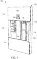
Fig. 1 is a perspective view of an electrical distribution system including an electrical distribution apparatus and an enclosure. -
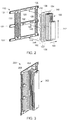
Fig. 2 is a partially exploded view of the electrical distribution apparatus shown inFig. 1 . -
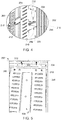
Fig. 3 is a perspective view of an electrical distribution apparatus including a bus bar assembly and a backplane coupled to a frame. -
Fig. 4 is an enlarged view of a portion of the electrical distribution apparatus shown inFig. 3 . -
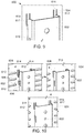
Fig. 5 is an enlarged view of a portion of an electrical distribution apparatus including positioning members. -
Fig. 6 is a perspective view of an electrical distribution apparatus including a bus bar assembly and a backplane. -
Fig. 7 is an enlarged view of a portion of the bus bar assembly shown inFig. 6 . -
Fig. 8 is an enlarged perspective view of an embodiment of an electrical distribution apparatus including a bus bar assembly coupled to a backplane by a bracket. -
Fig. 9 is an enlarged perspective view of an electrical distribution apparatus including a bus bar assembly coupled to a backplane. -
Fig. 10 is a series of front perspective views of engagement features of the electrical distribution apparatus shown inFig. 9 . -
Fig. 11 is a series of rear perspective views of engagement features of the electrical distribution apparatus shown inFig. 9 . - Although specific features of various embodiments may be shown in some drawings and not in others, this is for convenience only. Any feature of any drawing may be referenced and/or claimed in combination with any feature of any other drawing.
- In the following specification and the claims, reference will be made to a number of terms, which shall be defined to have the following meanings.
- The singular forms "a", "an", and "the" include plural references unless the context clearly dictates otherwise.
- "Optional" or "optionally" means that the subsequently described event or circumstance may or may not occur, and that the description includes instances where the event occurs and instances where it does not.
- Approximating language, as used herein throughout the specification and claims, may be applied to modify any quantitative representation that could permissibly vary without resulting in a change in the basic function to which it is related. Accordingly, a value modified by a term or terms, such as "about," "substantially," and "approximately," are not to be limited to the precise value specified. In at least some instances, the approximating language may correspond to the precision of an instrument for measuring the value. Here and throughout the specification and claims, range limitations may be combined and/or interchanged, such ranges are identified and include all the sub-ranges contained therein unless context or language indicates otherwise.
- Exemplary embodiments of distribution systems and methods of manufacturing distribution systems are described herein. The distribution systems generally include a bus bar assembly, a backplane, and a frame. The bus bar assembly and the backplane are modular components that are configured to couple to each other. In some embodiments, the bus bar assembly includes engagement features that extend into openings in the backplane. In further embodiments, the bus bar assembly includes openings that receive engagement features extending from the backplane. The frame is configured to support the backplane and the bus bar assembly when the backplane is coupled to the frame. In some embodiments, at least one of the backplane and the frame includes a positioning member that at least partially supports the backplane to allow positioning of the backplane relative to the frame. In further embodiments, the backplane includes handle portions that facilitate an operator handling the backplane.
-
Fig. 1 is a perspective view of an exemplaryelectrical distribution system 100 including anelectrical distribution apparatus 102 and anenclosure 104.Fig. 2 is a partially exploded view ofelectrical distribution apparatus 102.Electrical distribution apparatus 102 includes abus bar assembly 106 and abackplane 108 mounted to aframe 110 withinenclosure 104.Electrical distribution apparatus 102 is shown in the form of a panelboard. In alternative embodiments,electrical distribution system 100 includes anyelectrical distribution apparatus 102 that enableselectrical distribution system 100 to operate as described herein. - In the exemplary embodiment,
enclosure 104 includes a plurality ofpanels 112 isolating aninterior volume 114 ofenclosure 104 from an exterior environment.Enclosure 104 is configured to receivebus bar assembly 106 andbackplane 108 withininterior volume 114. In alternative embodiments,electrical distribution system 100 includes anyenclosure 104 that enableselectrical distribution system 100 to operate as described herein. - Also, in the exemplary embodiment,
electrical distribution system 100 is configured to electrically couple to a main power circuit, such as a three-phase power supply, and to distribute power to one or more branch circuits that are electrically coupled toelectrical distribution apparatus 102 through electrical devices. In the exemplary embodiment,electrical devices 116 are electrically coupled tobus bar assembly 106 along the perimeter ofbus bar assembly 106. In particular,electrical devices 116 include a main breaker electrically coupled tobus bar assembly 106 along an end of bus bar assembly, and a plurality of branch circuit breakers electrically coupled tobus bar assembly 106 along the sides ofbus bar assembly 106. In alternative embodiments,electrical distribution system 100 includes anyelectrical device 116 that enableselectrical distribution system 100 to operate as described herein. For example, in some embodiments,electrical distribution system 100 includes, without limitation, any of the following electrical devices: circuit breakers, circuit switching devices, electrical meters, fuses, intelligent devices, relays, protection devices such as surge protection devices and transient voltage surge suppressors, power supplies such as three-phase and four-phase power supplies, and circuit interrupters other than circuit breakers, such as contactors, motor starters, motor controllers, and other load controllers. - In reference to
Figs. 1 and2 ,backplane 108 defines a plurality ofelongate slots 122 arranged symmetrically about a central portion ofbackplane 108. Eachslot 122 is sized and shaped to receive a fastener to secure eachelectrical device 116 tobackplane 108.Slots 122 are arranged in two rows on each side ofbus bar assembly 106 whenbus bar assembly 106 is coupled tobackplane 108. The two rows include a bus side row and a load side row.Slots 122 are spaced from one another at a defined increment in alongitudinal direction 142 ofbackplane 108 such thatslots 122 align with mounting features (e.g., fasteners or fastener openings) onelectrical devices 116 whenelectrical devices 116 are connected tobus bar assembly 106 andbus bar assembly 106 is coupled toframe 110.Slots 122 are elongate in atransverse direction 144 orthogonal tolongitudinal direction 142 to provide flexibility in the mounting position ofelectrical devices 116. - As shown in
Fig. 2 ,bus bar assembly 106 includes a plurality of modular bus bars arranged in a stacked configuration. Each bus bar is configured to couple to one phase of a multi-phase power supply. In some embodiments, the bus bars are separated by spacers and/or bus bar insulators. In alternative embodiments,electrical distribution apparatus 102 includes anybus bar assembly 106 that enableselectrical distribution apparatus 102 to operate as described herein. - In the exemplary embodiment,
frame 110 includes a plurality of support members to which components ofelectrical distribution system 100 are mounted. In the exemplary embodiment,frame 110 includesvertical rails 130 andhorizontal rails Vertical rails 130 extend parallel to a longitudinal axis offrame 110, and are oriented substantially parallel to each other.Horizontal rails vertical rails 130 and substantially parallel to each other. An upperhorizontal rail 131 is coupled to a first end of eachvertical rail 130. A lowerhorizontal rail 133 is coupled to a second end of eachvertical rail 130. An intermediatehorizontal rail 132 is coupled to eachvertical rail 130 between the first end and the second end. Accordingly, intermediatehorizontal rail 132 is positioned between upperhorizontal rail 131 and lowerhorizontal rail 133. In the exemplary embodiment, intermediatehorizontal rail 132 is positioned approximately midway between upperhorizontal rail 131 and lowerhorizontal rail 133.Horizontal rails vertical rails 130 extend across a length and width offrame 110. Moreover, the thickness ofhorizontal rails vertical rails 130 defines a depth offrame 110. In alternative embodiments,electrical distribution apparatus 102 includes anyframe 110 that enableselectrical distribution apparatus 102 to operate as described herein. - Also, in the exemplary embodiment,
backplane 108 includes afirst end 134, asecond end 136, afirst side 138, and asecond side 140 collectively defining a perimeter ofbackplane 108.First side 138 andsecond side 140 each extend fromfirst end 134 tosecond end 136. Accordingly,backplane 108 extends a length inlongitudinal direction 142 fromfirst end 134 tosecond end 136, and a width in thetransverse direction 144. In alternative embodiments,electrical distribution apparatus 102 includes anybackplane 108 that enableselectrical distribution apparatus 102 to operate as described herein. - In addition, in the exemplary embodiment,
backplane 108 is coupled to eachhorizontal rail 132 offrame 110. In particular,first end 134 is coupled to upperhorizontal rail 131 andsecond end 136 is coupled to lowerhorizontal rail 133. Intermediatehorizontal rail 132 is coupled tobackplane 108 betweenfirst end 134 andsecond end 136.Backplane 108 is positioned onframe 110 such thatbackplane 108 is spaced fromvertical rails 130 by a lateral spacing sized to receiveelectrical devices 116. In some embodiments, the lateral spacing is varied to accommodateelectrical devices 116 having different sizes. For example, the lateral spacing is adjusted by varying the location at whichbackplane 108 is coupled toframe 110, or by varying the width ofbackplane 108 and/orbus bar assembly 106. - Also, in the exemplary embodiment,
backplane 108 includesflanges 146 extending fromfirst side 138 andsecond side 140. In the exemplary embodiment,backplane 108 includes fourflanges 146.Flanges 146 extend along the length ofbackplane 108 and provide support tobackplane 108. In addition,flanges 146 facilitate an operator handling andpositioning backplane 108. For example,flanges 146 include ahandle portion 148 for an operator to grasp.Handle portion 148 includes a recess and/or opening formed into eachflange 146. In addition, a portion offlange 146 is folded over, thickened, and/or rounded to remove sharp edges. In some embodiments,handle portion 148 includes a material that facilitates an operator graspinghandle portion 148, such as a gripping material and/or a loop. In alternative embodiments,backplane 108 includes anyflange 146 that enablesbackplane 108 to operate as described herein. In some embodiments,flanges 146 are omitted. In further embodiments,backplane 108 and/orbus bar assembly 106 includes handleportions 148 separate fromflanges 146. - Moreover, in the exemplary embodiment,
flanges 146 definenotches 150 and act as positioning members forbackplane 108.Notches 150 are configured to receive a portion offrame 110.Notches 150 include a curved edge that is positioned againstframe 110 to enablebackplane 108 to pivot relative to frame 110.Backplane 108 pivots between a first position and a second position. In the first position,backplane 108 is at least partially angled relative to frame 110. In the second position,first edge 134 andsecond edge 136 ofbackplane 108contact frame 110. During assembly, an operator positionsflanges 146 against bottomhorizontal rail 132 such thatflanges 146 andframe 110 at least partially supportbackplane 108.Flanges 146 are maintained against bottomhorizontal rail 132 andbackplane 108 is pivoted into the second position. In some embodiments,backplane 108 contacts each ofhorizontal rails backplane 108 is pivoted into position,backplane 108 is coupled toframe 110. In one embodiment, fasteners extend through openings inbackplane 108 andframe 110 to securebackplane 108 in position. In alternative embodiments,backplane 108 is positioned onframe 110 in any manner that enableselectrical distribution apparatus 102 to operate as described herein. For example, in some embodiments,backplane 108 is received bynotches 150 defined byframe 110 to facilitatepositioning backplane 108 relative to frame 110. - In the exemplary embodiment,
frame 110 defines alignment features 152 that facilitate aligningbackplane 108 relative to frame 106. Alignment features 152 include grooves that are configured to receive an edge ofbackplane 108 and alignbackplane 108 relative to frame 110. Alignment features 152 are defined by intermediatehorizontal rail 132 and are spaced fromvertical rails 130.Backplane 108 is positioned approximately midway betweenvertical rails 130 whenbackplane 108 is aligned with alignment features 152. In alternative embodiments,frame 110 includes any alignment features 152 that enableelectrical distribution system 100 to operate as described herein. For example, in some embodiments, at least one of upperhorizontal rail 131 and lowerhorizontal rail 133 definesalignment feature 152. In further embodiments, alignment features 152 include protuberances that abut against an edge ofbackplane 108. -
Fig. 3 is a perspective view of anelectrical distribution apparatus 200 including abus bar assembly 202 and abackplane 204 coupled to aframe 206.Fig. 4 is an enlarged view of a portion ofelectrical distribution apparatus 200.Frame 206 is configured to supportbus bar assembly 202 andbackplane 204 within enclosure 104 (shown inFig. 1 ).Bus bar assembly 202 andbackplane 204 are modular units that are configured to couple to each other. In particular,bus bar assembly 202 includes engagement features 208 that are configured to extend throughopenings 210 inbackplane 108 and couplebus bar assembly 202 tobackplane 204. Moreover, engagement features 208 at least partially supportbus bar assembly 202. - In the exemplary embodiment, engagement features 208 extend from
bus bar assembly 202 and have a hook shape. In particular, engagement features 208 extend outward from a surface ofsupport 220 and towardsbackplane 108. Moreover, engagement features 208 are integrally formed withsupport 220. In the exemplary embodiment, a catch portion of engagement features 208 extends at an angle relative to a base portion to define the hook shape. In the exemplary embodiment, engagement features 208 define an approximately 90° angle. The base portion extends substantially perpendicular to the surface ofsupport 220 and the catch portion extends substantially parallel to the surface. Accordingly, engagement features 208 are configured to catch or engage objects. In alternative embodiments,electrical distribution apparatus 200 includes anyengagement feature 208 that enableselectrical distribution apparatus 200 to operate as described herein. For example, in some embodiments, at least oneengagement feature 208 extends from a surface ofbackplane 204. In further embodiments, engagement features 208 are positionable. In some embodiments, engagement features 208 include, without limitation, any of the following: a mushroom shaped portion, an arrow shaped portion, a barb, a knob, a protuberance, a wedge, a teardrop shaped portion, and any other engagement component. - Also, in the exemplary embodiment, a central portion of
backplane 204 includesopenings 210 configured to receive engagement features 208.Openings 210 are elongate slots and extend in a vertical direction. In alternative embodiments,electrical distribution apparatus 200 includes anyopening 210 that enableselectrical distribution apparatus 200 to operate as described herein. For example, in some embodiments,electrical distribution apparatus 200 includes at least oneopening 210 defined bybus bar assembly 202. - Also, in the exemplary embodiment,
backplane 204 andbus bar assembly 202 includeopenings pins 212 securebus bar assembly 202 tobackplane 204 to inhibit movement ofbus bar assembly 202 relative tobackplane 204. In particular, lockingpins 212 inhibit movement ofbus bar assembly 202 in a longitudinal direction, and inhibit engagement features 208 disengaging frombackplane 204. Couplingtabs 218 extend from the front surface ofbackplane 204 and defineopenings 216.Supports 220 extend from the sides ofbus bar assembly 202 and define correspondingopenings 214. In alternative embodiments,electrical distribution apparatus 100 includes any locking feature that enableselectrical distribution apparatus 100 to operate as described herein. - In addition, in the exemplary embodiment, during assembly of
electrical distribution apparatus 200, engagement features 208 are inserted intoopenings 210 such that the hook portions of engagement features 208 extend beyondbackplane 204.Bus bar assembly 202 is then positioned such that engagement features 208 engagebackplane 204. When engaged withbackplane 204, engagement features 208 inhibit removal ofbus bar assembly 202 frombackplane 204. In the exemplary embodiment, lockingpins 212 are removably inserted throughopenings 214 andopenings 216. In alternative embodiments,bus bar assembly 202 is coupled tobackplane 204 in any manner that enableselectrical distribution system 100 to operate as described herein. -
Fig. 5 is an enlarged view of a portion of anelectrical distribution apparatus 300 including positioningmembers 302.Electrical distribution apparatus 300 includes positioningmembers 302, aframe 304, abackplane 306, and abus bar assembly 308.Bus bar assembly 308 is coupled tobackplane 306.Backplane 306 includesopenings 310 configured to receivepositioning members 302. Positioningmembers 302 extend from atop rail 312 offrame 304 and are configured to support at least a portion ofbus bar assembly 308 andbackplane 306. Accordingly, positioningmembers 302 facilitatepositioning backplane 306 between a first position and a second position. In the first position,backplane 306 is suspended by positioningmembers 302 such thatbackplane 306 is spaced fromframe 304. In the second position,backplane 306contacts frame 304. In the exemplary embodiment, positioningmembers 302 each include an elongate fastener, such as a shoulder bolt, that is coupled totop rail 312. In alternative embodiments,electrical distribution apparatus 300 includes anypositioning member 302 that enableselectrical distribution apparatus 300 to operate as described herein. For example, in some embodiments, positioningmembers 302 extend frombackplane 306. - During assembly of
electrical distribution apparatus 300, an operator positionsbackplane 306 such thatpositioning members 302 extend throughopenings 310. The operator then slidesbackplane 306 along positioningmembers 302 untilbackplane 306contacts frame 304.Openings 310 are sized to receivepositioning members 302 and facilitatebackplane 306 sliding along positioningmembers 302. In particular,openings 310 are larger than the heads of positioningmembers 302. Accordingly,openings 310 are oversized in comparison to openings configured to receive fasteners that securebackplane 306 to frame 304. Positioningmembers 302 andopenings 310 are positioned such thatbackplane 306 andframe 304 are aligned. In particular, the centers ofopenings 310 are positioned lower than the centers of other openings inbackplane 306 because positioningmembers 302 contact an edge ofopenings 310 and are not aligned with the center ofopenings 310. Afterbackplane 306 is aligned and positioned relative to frame 304, the operator securesbackplane 306 to frame 304. Accordingly, positioningmembers 302 facilitate theoperator positioning backplane 306 relative to frame 304 and facilitate theoperator coupling backplane 306 andframe 304. -
Fig. 6 is a perspective view of an embodiment of anelectrical distribution apparatus 400 including abus bar assembly 402 and abackplane 404.Fig. 7 is an enlarged view of a portion ofbus bar assembly 402.Bus bar assembly 402 includes bus bars 406,bus bar support 408, and engagement features 410, 412. Engagement features 410, 412 extend frombus bar support 408 and are configured to extend intoopenings 414 ofbackplane 404.Openings 414 are elongate slots and extend in a vertical direction.Openings 414 are aligned vertically in two rows in a central portion ofbackplane 404. Engagement features 410, 412 includehooks 410 and stops 412 that are sized to fit withinopenings 414 and inhibit movement ofbus bar assembly 402. In particular, hooks 410 are configured to engagebackplane 404 and couplebus bar assembly 402 tobackplane 404.Stops 412 are configured to abut against at least one edge ofopenings 414 and at least partially supportbus bar assembly 402. In addition,bus bar assembly 402 andbackplane 404 each include lockingopenings 416 configured to receive locking pins 212 (shown inFig. 4 ) that securebus bar assembly 402 tobackplane 404. In alternative embodiments,electrical distribution apparatus 400 includes any component that enableselectrical distribution apparatus 400 to operate as described herein. - In the exemplary embodiment, hooks 410 are oriented in different directions. In particular, a first set of
hooks 410 face downward and a second set ofhooks 410 face upward. Upward-facinghooks 410 engagebackplane 404 whenbus bar assembly 402 is moved upward. Downward-facinghooks 410 engagebackplane 404 whenbus bar assembly 402 is moved downward. Accordingly, hooks 410 inhibit movement ofbus bar assembly 402 in different directions. Eachstop 412 is positioned between a forward-facinghook 410 and an upward-facinghook 410. In alternative embodiments, engagement features 410, 412 are positioned in any manner that enableselectrical distribution apparatus 400 to operate as described herein. -
Fig. 8 is an enlarged perspective view of anelectrical distribution apparatus 500 including abus bar assembly 502 coupled to abackplane 504 by abracket 506.Bracket 506 includes orthogonal portions that contactbus bar assembly 502 andbackplane 504. In addition,bracket 506 definesopenings 508 configured to receivefasteners 510.Fasteners 510couple bracket 506 tobus bar assembly 502 andbackplane 504. Accordingly,bracket 506 inhibits longitudinal and transverse movement ofbus bar assembly 502 relative tobackplane 504. In alternative embodiments,bus bar assembly 502 andbackplane 504 are coupled together in any manner that enableselectrical distribution apparatus 500 to operate as described herein. -
Fig. 9 is an enlarged perspective view of anelectrical distribution apparatus 600 including abus bar assembly 602 coupled to abackplane 604.Fig. 10 is a series of front perspective views of engagement features 606, 608 ofelectrical distribution apparatus 600.Fig. 11 is a series of rear perspective views of engagement features 606, 608 ofelectrical distribution apparatus 600. Engagement features 606, 608 extend frombus bar assembly 602 and are configured to extend throughopenings backplane 604. Engagement features 606, 608 includehooks 606 and stops 608.Openings slots 610 and steppedopenings 612. In alternative embodiments,electrical distribution apparatus 600 includes anyengagement feature opening electrical distribution apparatus 600 to operate as described herein. - In the exemplary embodiment,
bus bar assembly 602 andbackplane 604 are configured such that engagement features 606, 608 extend intorespective openings slots 610 and stops 608 extend into steppedopenings 612. Adisplaceable member 614 extends through at least a portion of each steppedopening 612.Displaceable member 614 is positionable between a neutral position and a displaced position.Displaceable member 614 is biased towards the neutral position. When in the neutral position,displaceable member 614 is aligned withbackplane 604. When in the displaced position,displaceable member 614 is angled relative tobackplane 604. Engagement features 606, 608 are configured to movedisplaceable members 614 between the neutral position and the displaced position when engagement features 606, 608 are inserted intoopenings displaceable members 614 to move to the displaced position when stops 608 are inserted into steppedopenings 612. Displaceablemembers 614 return to the neutral position when stops 608 are positioned within a bottom portion of steppedopenings 612 or removed from steppedopenings 612. When stops 608 extend into steppedopenings 612 anddisplaceable members 614 are in the neutral position,displaceable members 614 inhibit movement ofbus bar assembly 602. In particular,displaceable members 614 abut againststops 608 and inhibit engagement features 606, 608 disengaging frombackplane 604. Accordingly, engagement features 606, 608,openings displaceable members 614 couplebus bar assembly 602 tobackplane 604. In alternative embodiments,bus bar assembly 602 is coupled tobackplane 604 in any manner that enableselectrical distribution apparatus 500 to operate as described herein. - In reference to
Figs. 1 ,3 ,4 , and10 a method of assembling an electrical distribution system includes positioningbus bar assembly 106 relative to backplane 108 such that engagement features 208 extend intoopenings 210. The method also includes positioningbus bar assembly 106 such that engagement features 208 engage a surface. In some embodiments, lockingpins 212 are inserted intoopenings bus bar assembly 106 andbackplane 108 to inhibit movement ofbus bar assembly 106 relative tobackplane 108. The method further includespositioning backplane 108 such thatpositioning members 302 support at least a portion ofbackplane 108 and movingbackplane 108 between a first position and a second position whilebackplane 108 is supported by positioningmembers 302. In some embodiments,backplane 108 is pivoted relative to frame 110. In further embodiments,backplane 108 slides along positioningmembers 302. The method also includescoupling backplane 108 to frame 110. - The distribution systems described above generally include a bus bar assembly, a backplane, and a frame. The bus bar assembly and the backplane are modular components that are coupled together at an installation site. In some embodiments, the bus bar assembly includes engagement features that extend into openings in the backplane and couple the bus bar assembly to the backplane. In further embodiments, the backplane includes engagement features that extend into openings in the bus bar assembly. The backplane is coupled to and supported by the frame. In some embodiments, at least one of the backplane and the frame includes a positioning member that at least partially supports the backplane and facilitates coupling the backplane to the frame.
- An exemplary technical effect of the methods, systems, and apparatus described herein includes at least one of: (a) reducing cost and time required to assemble electrical distribution systems; (b) providing modular components for an electrical distribution apparatus; (c) providing electrical distribution apparatuses that have a scalable design; (d) providing electrical distribution apparatuses that are ergonomic for operators to handle; (e) reducing the cost and time required to install electrical distribution apparatus; (f) increase shipping and manufacturing options for electrical distribution apparatuses; (g) provide electrical distribution apparatuses that have improved paths to market; (h) provide electrical distribution apparatuses that are easier for distributors to stock; and (i) provide electrical distribution apparatuses that are manufactured at an increased number of distributed manufacturing sites.
- Exemplary embodiments of electrical distribution apparatuses and methods of assembling electrical distribution apparatuses are described above in detail. The electrical distribution apparatuses and methods are not limited to the specific embodiments described herein but, rather, components of the electrical distribution apparatuses and/or operations of the methods may be utilized independently and separately from other components and/or operations described herein. Further, the described components and/or operations may also be defined in, or used in combination with, other systems, methods, and/or devices, and are not limited to practice with only the electrical distribution systems and apparatuses described herein.
- The order of execution or performance of the operations in the embodiments of the disclosure illustrated and described herein is not essential, unless otherwise specified. That is, the operations may be performed in any order, unless otherwise specified, and embodiments of the disclosure may include additional or fewer operations than those disclosed herein. For example, it is contemplated that executing or performing a particular operation before, contemporaneously with, or after another operation is within the scope of aspects of the disclosure.
Claims (11)
Applications Claiming Priority (1)
| Application Number | Priority Date | Filing Date | Title |
|---|---|---|---|
| US15/252,904 US10250018B2 (en) | 2016-08-31 | 2016-08-31 | Electrical distribution apparatus and methods of assembling same |
Publications (2)
| Publication Number | Publication Date |
|---|---|
| EP3291389A1 true EP3291389A1 (en) | 2018-03-07 |
| EP3291389B1 EP3291389B1 (en) | 2024-06-26 |
Family
ID=59686828
Family Applications (1)
| Application Number | Title | Priority Date | Filing Date |
|---|---|---|---|
| EP17187382.1A Active EP3291389B1 (en) | 2016-08-31 | 2017-08-23 | Electrical distribution apparatus |
Country Status (3)
| Country | Link |
|---|---|
| US (1) | US10250018B2 (en) |
| EP (1) | EP3291389B1 (en) |
| CN (1) | CN107785782B (en) |
Families Citing this family (2)
| Publication number | Priority date | Publication date | Assignee | Title |
|---|---|---|---|---|
| US10164387B2 (en) * | 2015-02-09 | 2018-12-25 | Abb Schweiz Ag | Electrical device, electrical distribution system, and methods of assembling same |
| CN209435667U (en) * | 2018-11-22 | 2019-09-24 | 京东方科技集团股份有限公司 | Back board structure |
Citations (3)
| Publication number | Priority date | Publication date | Assignee | Title |
|---|---|---|---|---|
| US4713728A (en) * | 1985-02-25 | 1987-12-15 | General Electric Company | Lighting circuit breaker panelboard modular assembly |
| US5875093A (en) * | 1997-06-02 | 1999-02-23 | Eaton Corporation | Electrical distribution panel interior base assembly |
| US20160233649A1 (en) * | 2015-02-09 | 2016-08-11 | General Electric Company | Electrical device, electrical distribution system, and methods of assembling same |
Family Cites Families (33)
| Publication number | Priority date | Publication date | Assignee | Title |
|---|---|---|---|---|
| US2914708A (en) * | 1953-06-12 | 1959-11-24 | Ite Circuit Breaker Ltd | Panel board construction |
| US3354357A (en) | 1966-12-20 | 1967-11-21 | Square D Co | Electrical panelboard |
| US3346777A (en) * | 1966-12-20 | 1967-10-10 | Square D Co | Electric circuit breaker and mounting means therefor |
| US3721864A (en) | 1971-05-20 | 1973-03-20 | Square D Co | Electrical panelboard with stacked bus bars and mounting pan formed of grooved bars |
| US4031433A (en) | 1974-05-30 | 1977-06-21 | General Electric Company | Insulative modular mounting panels for electrical switchboards |
| CA1087721A (en) | 1977-05-16 | 1980-10-14 | Robert G. Anderson | Bus bar assembly for distribution loadcentres |
| US4153318A (en) | 1977-10-17 | 1979-05-08 | Square D Company | Bus stab for panelboard assembly |
| US4588854A (en) | 1983-03-02 | 1986-05-13 | Switchcraft, Inc. | Panel mountable module housing |
| US4783718A (en) * | 1985-02-25 | 1988-11-08 | General Electric Company | Lighting circuit breaker panelboard modular assembly |
| US4744003A (en) | 1987-04-07 | 1988-05-10 | Eaton Corporation | Power distribution panelboard |
| US5092787A (en) * | 1989-08-16 | 1992-03-03 | Amp Incorporated | Power distribution for modular furniture units |
| US5024627A (en) * | 1990-06-29 | 1991-06-18 | Amp Incorporated | Float mounted receptacle contact assembly for card cage |
| US5046173A (en) | 1990-10-18 | 1991-09-03 | General Electric Company | Single branch circuit breaker support |
| US5343356A (en) * | 1992-12-31 | 1994-08-30 | Siemens Energy & Automation, Inc. | Panelboard |
| US5530205A (en) | 1994-07-29 | 1996-06-25 | Eaton Corporation | Apparatus for securing bus bars to switches in alternative positions |
| US5954823A (en) * | 1995-11-13 | 1999-09-21 | International Business Machines Corporation | Redundant power distribution in an information processing system |
| US5969938A (en) * | 1996-11-15 | 1999-10-19 | Lucent Technologies Inc. | Modular power supply chassis employing a suspended bus bar assembly |
| US6061230A (en) | 1997-12-08 | 2000-05-09 | General Electric Company | Electric power distribution panelboard/switchboard assembly |
| DE19948329C2 (en) * | 1999-10-07 | 2002-08-14 | Eberhard Gawehn | Control cabinet and process for its manufacture |
| US6486406B1 (en) | 2000-11-14 | 2002-11-26 | 3Com Corporation | Latching apparatus and method for providing radial alignment of a housing mounted on a circuit board |
| US7035115B2 (en) * | 2003-04-11 | 2006-04-25 | Rockwell Automation Technologies, Inc. | Multi-axis motor control with high voltage backplane |
| US7520759B2 (en) * | 2006-06-28 | 2009-04-21 | Eaton Corporation | Modular bus assembly for a loadcenter |
| US7440262B2 (en) | 2006-12-06 | 2008-10-21 | Adc Telecommunications, Inc. | Modular power distribution system and methods |
| US20080158786A1 (en) * | 2006-12-27 | 2008-07-03 | General Electric Company | Panelboards having support rails |
| DE102008012570B4 (en) | 2008-03-04 | 2014-02-13 | Infineon Technologies Ag | Power semiconductor module system, power semiconductor module assembly, and method of making a power semiconductor module assembly |
| US8379374B2 (en) * | 2010-07-16 | 2013-02-19 | Rockwell Automation Technologies, Inc. | Bus to bus power interconnect |
| CN102623901A (en) * | 2011-01-28 | 2012-08-01 | 施耐德电器工业公司 | Power distribution cabinet installation plate support and installation method thereof |
| JP2012222577A (en) * | 2011-04-07 | 2012-11-12 | Funai Electric Co Ltd | Equipment board attachment structure |
| TW201320061A (en) | 2011-11-04 | 2013-05-16 | Hon Hai Prec Ind Co Ltd | HDD partition sheet and chassis of electronic device having the same |
| FR3003407B1 (en) * | 2013-03-12 | 2015-03-06 | Schneider Electric Ind Sas | ELECTRICAL ENVELOPE WITH IMPROVED MECHANICAL ARRANGEMENT |
| JP6229361B2 (en) * | 2013-08-01 | 2017-11-15 | 富士通株式会社 | Electronic equipment and board unit |
| US9716372B2 (en) | 2015-06-18 | 2017-07-25 | Eaton Corporation | Switchboard for power distribution system |
| US9812848B2 (en) * | 2015-10-30 | 2017-11-07 | Rockwell Automation Technologies, Inc. | Fixed vertical distribution bus bar |
-
2016
- 2016-08-31 US US15/252,904 patent/US10250018B2/en active Active
-
2017
- 2017-08-23 EP EP17187382.1A patent/EP3291389B1/en active Active
- 2017-08-31 CN CN201710776759.2A patent/CN107785782B/en active Active
Patent Citations (3)
| Publication number | Priority date | Publication date | Assignee | Title |
|---|---|---|---|---|
| US4713728A (en) * | 1985-02-25 | 1987-12-15 | General Electric Company | Lighting circuit breaker panelboard modular assembly |
| US5875093A (en) * | 1997-06-02 | 1999-02-23 | Eaton Corporation | Electrical distribution panel interior base assembly |
| US20160233649A1 (en) * | 2015-02-09 | 2016-08-11 | General Electric Company | Electrical device, electrical distribution system, and methods of assembling same |
Also Published As
| Publication number | Publication date |
|---|---|
| CN107785782A (en) | 2018-03-09 |
| CN107785782B (en) | 2021-08-10 |
| EP3291389B1 (en) | 2024-06-26 |
| US20180062359A1 (en) | 2018-03-01 |
| US10250018B2 (en) | 2019-04-02 |
Similar Documents
| Publication | Publication Date | Title |
|---|---|---|
| EP3246995B1 (en) | Busbar system | |
| EP3291390B1 (en) | Electrical distribution apparatus and methods of assembling same | |
| US7719823B2 (en) | Modular insulation system | |
| US9257824B2 (en) | Electrical enclosure with improved mechanical arrangement | |
| EP3291389B1 (en) | Electrical distribution apparatus | |
| EP3066901B1 (en) | Component assembly system | |
| US2837699A (en) | Panelboard construction | |
| US4791530A (en) | Insulating barrier system for switchgear | |
| WO2015063294A1 (en) | Functional component for a component construction system | |
| US9748743B2 (en) | Electrical panelboard assemblies and methods | |
| RU2321122C1 (en) | Low-voltage switchgear and control gear | |
| EP0587820B1 (en) | Low-voltage switchgear for the output or distribution of electric power | |
| KR101528600B1 (en) | Device for Fixing Transformer | |
| EP2559121A1 (en) | Blank for forming a drawer for an electrical cabinet | |
| US7224577B2 (en) | Mounting plate system | |
| DE102020213607B4 (en) | Fastening device for fastening an assembly via a mounting rail | |
| US20060082264A1 (en) | Strap support barrier | |
| KR20170024938A (en) | Motor Control center | |
| US20060118320A1 (en) | Alignment arrangement for a circuit breaker cradle | |
| US11563311B2 (en) | Device insertion and removal method for electrical equipment | |
| US12620785B2 (en) | Plug-in socket system | |
| KR20130004254U (en) | Fixation structure for busbar of motor control center | |
| DE9204391U1 (en) | Withdrawable low-voltage switchgear for supplying or distributing electrical energy | |
| CN121488319A (en) | The circuit breaker accessories of the I-line switchboard refer to the safety busbar stack. | |
| DE10332679A1 (en) | Multi-pole current collector rail system arrangement for installation devices in switchgear housing, has adjacent collector rails spaced to allow their facing surfaces to be fitted with installation devices |
Legal Events
| Date | Code | Title | Description |
|---|---|---|---|
| PUAI | Public reference made under article 153(3) epc to a published international application that has entered the european phase |
Free format text: ORIGINAL CODE: 0009012 |
|
| STAA | Information on the status of an ep patent application or granted ep patent |
Free format text: STATUS: THE APPLICATION HAS BEEN PUBLISHED |
|
| AK | Designated contracting states |
Kind code of ref document: A1 Designated state(s): AL AT BE BG CH CY CZ DE DK EE ES FI FR GB GR HR HU IE IS IT LI LT LU LV MC MK MT NL NO PL PT RO RS SE SI SK SM TR |
|
| AX | Request for extension of the european patent |
Extension state: BA ME |
|
| STAA | Information on the status of an ep patent application or granted ep patent |
Free format text: STATUS: REQUEST FOR EXAMINATION WAS MADE |
|
| 17P | Request for examination filed |
Effective date: 20190102 |
|
| RBV | Designated contracting states (corrected) |
Designated state(s): AL AT BE BG CH CY CZ DE DK EE ES FI FR GB GR HR HU IE IS IT LI LT LU LV MC MK MT NL NO PL PT RO RS SE SI SK SM TR |
|
| RAP1 | Party data changed (applicant data changed or rights of an application transferred) |
Owner name: ABB SCHWEIZ AG |
|
| STAA | Information on the status of an ep patent application or granted ep patent |
Free format text: STATUS: EXAMINATION IS IN PROGRESS |
|
| 17Q | First examination report despatched |
Effective date: 20200330 |
|
| RAP3 | Party data changed (applicant data changed or rights of an application transferred) |
Owner name: ABB SCHWEIZ AG |
|
| REG | Reference to a national code |
Ref country code: DE Ref legal event code: R079 Free format text: PREVIOUS MAIN CLASS: H02B0001056000 Ipc: H02B0001320000 Ref country code: DE Ref legal event code: R079 Ref document number: 602017082784 Country of ref document: DE Free format text: PREVIOUS MAIN CLASS: H02B0001056000 Ipc: H02B0001320000 |
|
| GRAP | Despatch of communication of intention to grant a patent |
Free format text: ORIGINAL CODE: EPIDOSNIGR1 |
|
| STAA | Information on the status of an ep patent application or granted ep patent |
Free format text: STATUS: GRANT OF PATENT IS INTENDED |
|
| RIC1 | Information provided on ipc code assigned before grant |
Ipc: H02B 1/21 20060101ALN20231220BHEP Ipc: H02B 1/056 20060101ALN20231220BHEP Ipc: H02B 1/32 20060101AFI20231220BHEP |
|
| INTG | Intention to grant announced |
Effective date: 20240122 |
|
| GRAS | Grant fee paid |
Free format text: ORIGINAL CODE: EPIDOSNIGR3 |
|
| GRAA | (expected) grant |
Free format text: ORIGINAL CODE: 0009210 |
|
| STAA | Information on the status of an ep patent application or granted ep patent |
Free format text: STATUS: THE PATENT HAS BEEN GRANTED |
|
| AK | Designated contracting states |
Kind code of ref document: B1 Designated state(s): AL AT BE BG CH CY CZ DE DK EE ES FI FR GB GR HR HU IE IS IT LI LT LU LV MC MK MT NL NO PL PT RO RS SE SI SK SM TR |
|
| REG | Reference to a national code |
Ref country code: GB Ref legal event code: FG4D |
|
| REG | Reference to a national code |
Ref country code: CH Ref legal event code: EP |
|
| REG | Reference to a national code |
Ref country code: DE Ref legal event code: R096 Ref document number: 602017082784 Country of ref document: DE |
|
| PG25 | Lapsed in a contracting state [announced via postgrant information from national office to epo] |
Ref country code: BG Free format text: LAPSE BECAUSE OF FAILURE TO SUBMIT A TRANSLATION OF THE DESCRIPTION OR TO PAY THE FEE WITHIN THE PRESCRIBED TIME-LIMIT Effective date: 20240626 |
|
| PG25 | Lapsed in a contracting state [announced via postgrant information from national office to epo] |
Ref country code: FI Free format text: LAPSE BECAUSE OF FAILURE TO SUBMIT A TRANSLATION OF THE DESCRIPTION OR TO PAY THE FEE WITHIN THE PRESCRIBED TIME-LIMIT Effective date: 20240626 Ref country code: HR Free format text: LAPSE BECAUSE OF FAILURE TO SUBMIT A TRANSLATION OF THE DESCRIPTION OR TO PAY THE FEE WITHIN THE PRESCRIBED TIME-LIMIT Effective date: 20240626 |
|
| REG | Reference to a national code |
Ref country code: LT Ref legal event code: MG9D |
|
| PG25 | Lapsed in a contracting state [announced via postgrant information from national office to epo] |
Ref country code: GR Free format text: LAPSE BECAUSE OF FAILURE TO SUBMIT A TRANSLATION OF THE DESCRIPTION OR TO PAY THE FEE WITHIN THE PRESCRIBED TIME-LIMIT Effective date: 20240927 |
|
| PG25 | Lapsed in a contracting state [announced via postgrant information from national office to epo] |
Ref country code: LV Free format text: LAPSE BECAUSE OF FAILURE TO SUBMIT A TRANSLATION OF THE DESCRIPTION OR TO PAY THE FEE WITHIN THE PRESCRIBED TIME-LIMIT Effective date: 20240626 |
|
| REG | Reference to a national code |
Ref country code: NL Ref legal event code: MP Effective date: 20240626 |
|
| PG25 | Lapsed in a contracting state [announced via postgrant information from national office to epo] |
Ref country code: NO Free format text: LAPSE BECAUSE OF FAILURE TO SUBMIT A TRANSLATION OF THE DESCRIPTION OR TO PAY THE FEE WITHIN THE PRESCRIBED TIME-LIMIT Effective date: 20240926 Ref country code: LV Free format text: LAPSE BECAUSE OF FAILURE TO SUBMIT A TRANSLATION OF THE DESCRIPTION OR TO PAY THE FEE WITHIN THE PRESCRIBED TIME-LIMIT Effective date: 20240626 Ref country code: HR Free format text: LAPSE BECAUSE OF FAILURE TO SUBMIT A TRANSLATION OF THE DESCRIPTION OR TO PAY THE FEE WITHIN THE PRESCRIBED TIME-LIMIT Effective date: 20240626 Ref country code: GR Free format text: LAPSE BECAUSE OF FAILURE TO SUBMIT A TRANSLATION OF THE DESCRIPTION OR TO PAY THE FEE WITHIN THE PRESCRIBED TIME-LIMIT Effective date: 20240927 Ref country code: FI Free format text: LAPSE BECAUSE OF FAILURE TO SUBMIT A TRANSLATION OF THE DESCRIPTION OR TO PAY THE FEE WITHIN THE PRESCRIBED TIME-LIMIT Effective date: 20240626 Ref country code: BG Free format text: LAPSE BECAUSE OF FAILURE TO SUBMIT A TRANSLATION OF THE DESCRIPTION OR TO PAY THE FEE WITHIN THE PRESCRIBED TIME-LIMIT Effective date: 20240626 Ref country code: RS Free format text: LAPSE BECAUSE OF FAILURE TO SUBMIT A TRANSLATION OF THE DESCRIPTION OR TO PAY THE FEE WITHIN THE PRESCRIBED TIME-LIMIT Effective date: 20240926 |
|
| PG25 | Lapsed in a contracting state [announced via postgrant information from national office to epo] |
Ref country code: NL Free format text: LAPSE BECAUSE OF FAILURE TO SUBMIT A TRANSLATION OF THE DESCRIPTION OR TO PAY THE FEE WITHIN THE PRESCRIBED TIME-LIMIT Effective date: 20240626 |
|
| REG | Reference to a national code |
Ref country code: AT Ref legal event code: MK05 Ref document number: 1698508 Country of ref document: AT Kind code of ref document: T Effective date: 20240626 |
|
| PG25 | Lapsed in a contracting state [announced via postgrant information from national office to epo] |
Ref country code: NL Free format text: LAPSE BECAUSE OF FAILURE TO SUBMIT A TRANSLATION OF THE DESCRIPTION OR TO PAY THE FEE WITHIN THE PRESCRIBED TIME-LIMIT Effective date: 20240626 |
|
| PG25 | Lapsed in a contracting state [announced via postgrant information from national office to epo] |
Ref country code: PT Free format text: LAPSE BECAUSE OF FAILURE TO SUBMIT A TRANSLATION OF THE DESCRIPTION OR TO PAY THE FEE WITHIN THE PRESCRIBED TIME-LIMIT Effective date: 20241028 |
|
| PG25 | Lapsed in a contracting state [announced via postgrant information from national office to epo] |
Ref country code: PT Free format text: LAPSE BECAUSE OF FAILURE TO SUBMIT A TRANSLATION OF THE DESCRIPTION OR TO PAY THE FEE WITHIN THE PRESCRIBED TIME-LIMIT Effective date: 20241028 |
|
| PG25 | Lapsed in a contracting state [announced via postgrant information from national office to epo] |
Ref country code: PL Free format text: LAPSE BECAUSE OF FAILURE TO SUBMIT A TRANSLATION OF THE DESCRIPTION OR TO PAY THE FEE WITHIN THE PRESCRIBED TIME-LIMIT Effective date: 20240626 |
|
| PG25 | Lapsed in a contracting state [announced via postgrant information from national office to epo] |
Ref country code: EE Free format text: LAPSE BECAUSE OF FAILURE TO SUBMIT A TRANSLATION OF THE DESCRIPTION OR TO PAY THE FEE WITHIN THE PRESCRIBED TIME-LIMIT Effective date: 20240626 |
|
| PG25 | Lapsed in a contracting state [announced via postgrant information from national office to epo] |
Ref country code: IS Free format text: LAPSE BECAUSE OF FAILURE TO SUBMIT A TRANSLATION OF THE DESCRIPTION OR TO PAY THE FEE WITHIN THE PRESCRIBED TIME-LIMIT Effective date: 20241026 Ref country code: AT Free format text: LAPSE BECAUSE OF FAILURE TO SUBMIT A TRANSLATION OF THE DESCRIPTION OR TO PAY THE FEE WITHIN THE PRESCRIBED TIME-LIMIT Effective date: 20240626 |
|
| PG25 | Lapsed in a contracting state [announced via postgrant information from national office to epo] |
Ref country code: CZ Free format text: LAPSE BECAUSE OF FAILURE TO SUBMIT A TRANSLATION OF THE DESCRIPTION OR TO PAY THE FEE WITHIN THE PRESCRIBED TIME-LIMIT Effective date: 20240626 |
|
| PG25 | Lapsed in a contracting state [announced via postgrant information from national office to epo] |
Ref country code: RO Free format text: LAPSE BECAUSE OF FAILURE TO SUBMIT A TRANSLATION OF THE DESCRIPTION OR TO PAY THE FEE WITHIN THE PRESCRIBED TIME-LIMIT Effective date: 20240626 Ref country code: SK Free format text: LAPSE BECAUSE OF FAILURE TO SUBMIT A TRANSLATION OF THE DESCRIPTION OR TO PAY THE FEE WITHIN THE PRESCRIBED TIME-LIMIT Effective date: 20240626 |
|
| PG25 | Lapsed in a contracting state [announced via postgrant information from national office to epo] |
Ref country code: SM Free format text: LAPSE BECAUSE OF FAILURE TO SUBMIT A TRANSLATION OF THE DESCRIPTION OR TO PAY THE FEE WITHIN THE PRESCRIBED TIME-LIMIT Effective date: 20240626 Ref country code: ES Free format text: LAPSE BECAUSE OF FAILURE TO SUBMIT A TRANSLATION OF THE DESCRIPTION OR TO PAY THE FEE WITHIN THE PRESCRIBED TIME-LIMIT Effective date: 20240626 |
|
| PG25 | Lapsed in a contracting state [announced via postgrant information from national office to epo] |
Ref country code: SM Free format text: LAPSE BECAUSE OF FAILURE TO SUBMIT A TRANSLATION OF THE DESCRIPTION OR TO PAY THE FEE WITHIN THE PRESCRIBED TIME-LIMIT Effective date: 20240626 Ref country code: SK Free format text: LAPSE BECAUSE OF FAILURE TO SUBMIT A TRANSLATION OF THE DESCRIPTION OR TO PAY THE FEE WITHIN THE PRESCRIBED TIME-LIMIT Effective date: 20240626 Ref country code: RO Free format text: LAPSE BECAUSE OF FAILURE TO SUBMIT A TRANSLATION OF THE DESCRIPTION OR TO PAY THE FEE WITHIN THE PRESCRIBED TIME-LIMIT Effective date: 20240626 Ref country code: PL Free format text: LAPSE BECAUSE OF FAILURE TO SUBMIT A TRANSLATION OF THE DESCRIPTION OR TO PAY THE FEE WITHIN THE PRESCRIBED TIME-LIMIT Effective date: 20240626 Ref country code: IS Free format text: LAPSE BECAUSE OF FAILURE TO SUBMIT A TRANSLATION OF THE DESCRIPTION OR TO PAY THE FEE WITHIN THE PRESCRIBED TIME-LIMIT Effective date: 20241026 Ref country code: ES Free format text: LAPSE BECAUSE OF FAILURE TO SUBMIT A TRANSLATION OF THE DESCRIPTION OR TO PAY THE FEE WITHIN THE PRESCRIBED TIME-LIMIT Effective date: 20240626 Ref country code: EE Free format text: LAPSE BECAUSE OF FAILURE TO SUBMIT A TRANSLATION OF THE DESCRIPTION OR TO PAY THE FEE WITHIN THE PRESCRIBED TIME-LIMIT Effective date: 20240626 Ref country code: CZ Free format text: LAPSE BECAUSE OF FAILURE TO SUBMIT A TRANSLATION OF THE DESCRIPTION OR TO PAY THE FEE WITHIN THE PRESCRIBED TIME-LIMIT Effective date: 20240626 Ref country code: AT Free format text: LAPSE BECAUSE OF FAILURE TO SUBMIT A TRANSLATION OF THE DESCRIPTION OR TO PAY THE FEE WITHIN THE PRESCRIBED TIME-LIMIT Effective date: 20240626 |
|
| REG | Reference to a national code |
Ref country code: DE Ref legal event code: R097 Ref document number: 602017082784 Country of ref document: DE |
|
| REG | Reference to a national code |
Ref country code: CH Ref legal event code: PL |
|
| PG25 | Lapsed in a contracting state [announced via postgrant information from national office to epo] |
Ref country code: DK Free format text: LAPSE BECAUSE OF FAILURE TO SUBMIT A TRANSLATION OF THE DESCRIPTION OR TO PAY THE FEE WITHIN THE PRESCRIBED TIME-LIMIT Effective date: 20240626 |
|
| PG25 | Lapsed in a contracting state [announced via postgrant information from national office to epo] |
Ref country code: LU Free format text: LAPSE BECAUSE OF NON-PAYMENT OF DUE FEES Effective date: 20240823 |
|
| PG25 | Lapsed in a contracting state [announced via postgrant information from national office to epo] |
Ref country code: MC Free format text: LAPSE BECAUSE OF FAILURE TO SUBMIT A TRANSLATION OF THE DESCRIPTION OR TO PAY THE FEE WITHIN THE PRESCRIBED TIME-LIMIT Effective date: 20240626 Ref country code: CH Free format text: LAPSE BECAUSE OF NON-PAYMENT OF DUE FEES Effective date: 20240831 |
|
| PLBE | No opposition filed within time limit |
Free format text: ORIGINAL CODE: 0009261 |
|
| STAA | Information on the status of an ep patent application or granted ep patent |
Free format text: STATUS: NO OPPOSITION FILED WITHIN TIME LIMIT |
|
| GBPC | Gb: european patent ceased through non-payment of renewal fee |
Effective date: 20240926 |
|
| 26N | No opposition filed |
Effective date: 20250327 |
|
| REG | Reference to a national code |
Ref country code: BE Ref legal event code: MM Effective date: 20240831 |
|
| PG25 | Lapsed in a contracting state [announced via postgrant information from national office to epo] |
Ref country code: GB Free format text: LAPSE BECAUSE OF NON-PAYMENT OF DUE FEES Effective date: 20240926 |
|
| PG25 | Lapsed in a contracting state [announced via postgrant information from national office to epo] |
Ref country code: BE Free format text: LAPSE BECAUSE OF NON-PAYMENT OF DUE FEES Effective date: 20240831 |
|
| PG25 | Lapsed in a contracting state [announced via postgrant information from national office to epo] |
Ref country code: FR Free format text: LAPSE BECAUSE OF NON-PAYMENT OF DUE FEES Effective date: 20240826 |
|
| PG25 | Lapsed in a contracting state [announced via postgrant information from national office to epo] |
Ref country code: IE Free format text: LAPSE BECAUSE OF NON-PAYMENT OF DUE FEES Effective date: 20240823 |
|
| PG25 | Lapsed in a contracting state [announced via postgrant information from national office to epo] |
Ref country code: SE Free format text: LAPSE BECAUSE OF FAILURE TO SUBMIT A TRANSLATION OF THE DESCRIPTION OR TO PAY THE FEE WITHIN THE PRESCRIBED TIME-LIMIT Effective date: 20240626 |
|
| PGFP | Annual fee paid to national office [announced via postgrant information from national office to epo] |
Ref country code: DE Payment date: 20250820 Year of fee payment: 9 |
|
| PGFP | Annual fee paid to national office [announced via postgrant information from national office to epo] |
Ref country code: IT Payment date: 20250825 Year of fee payment: 9 |
|
| PG25 | Lapsed in a contracting state [announced via postgrant information from national office to epo] |
Ref country code: CY Free format text: LAPSE BECAUSE OF FAILURE TO SUBMIT A TRANSLATION OF THE DESCRIPTION OR TO PAY THE FEE WITHIN THE PRESCRIBED TIME-LIMIT; INVALID AB INITIO Effective date: 20170823 |
|
| PG25 | Lapsed in a contracting state [announced via postgrant information from national office to epo] |
Ref country code: HU Free format text: LAPSE BECAUSE OF FAILURE TO SUBMIT A TRANSLATION OF THE DESCRIPTION OR TO PAY THE FEE WITHIN THE PRESCRIBED TIME-LIMIT; INVALID AB INITIO Effective date: 20170823 |
|
| PG25 | Lapsed in a contracting state [announced via postgrant information from national office to epo] |
Ref country code: TR Free format text: LAPSE BECAUSE OF FAILURE TO SUBMIT A TRANSLATION OF THE DESCRIPTION OR TO PAY THE FEE WITHIN THE PRESCRIBED TIME-LIMIT Effective date: 20240626 |
|
| PG25 | Lapsed in a contracting state [announced via postgrant information from national office to epo] |
Ref country code: SI Free format text: LAPSE BECAUSE OF FAILURE TO SUBMIT A TRANSLATION OF THE DESCRIPTION OR TO PAY THE FEE WITHIN THE PRESCRIBED TIME-LIMIT Effective date: 20240626 |
|
| PG25 | Lapsed in a contracting state [announced via postgrant information from national office to epo] |
Ref country code: LT Free format text: LAPSE BECAUSE OF FAILURE TO SUBMIT A TRANSLATION OF THE DESCRIPTION OR TO PAY THE FEE WITHIN THE PRESCRIBED TIME-LIMIT Effective date: 20240626 |