EP3291347A1 - Fuel-cell power generation system comprising initial correction of the flow rate of fluid supplying device - Google Patents
Fuel-cell power generation system comprising initial correction of the flow rate of fluid supplying device Download PDFInfo
- Publication number
- EP3291347A1 EP3291347A1 EP17179166.8A EP17179166A EP3291347A1 EP 3291347 A1 EP3291347 A1 EP 3291347A1 EP 17179166 A EP17179166 A EP 17179166A EP 3291347 A1 EP3291347 A1 EP 3291347A1
- Authority
- EP
- European Patent Office
- Prior art keywords
- fuel
- flow rate
- setting value
- value
- supplying device
- Prior art date
- Legal status (The legal status is an assumption and is not a legal conclusion. Google has not performed a legal analysis and makes no representation as to the accuracy of the status listed.)
- Withdrawn
Links
- 239000012530 fluid Substances 0.000 title claims abstract description 56
- 238000010248 power generation Methods 0.000 title claims abstract description 42
- 238000012937 correction Methods 0.000 title claims description 81
- 238000012545 processing Methods 0.000 claims abstract description 26
- 238000009434 installation Methods 0.000 claims abstract description 10
- 230000004913 activation Effects 0.000 claims abstract description 9
- 238000011989 factory acceptance test Methods 0.000 claims abstract description 9
- 238000012423 maintenance Methods 0.000 claims abstract description 9
- 239000000446 fuel Substances 0.000 claims description 72
- 239000007789 gas Substances 0.000 claims description 19
- 239000003915 liquefied petroleum gas Substances 0.000 claims description 8
- 239000003570 air Substances 0.000 description 13
- 230000009471 action Effects 0.000 description 12
- 230000008859 change Effects 0.000 description 11
- 238000010586 diagram Methods 0.000 description 8
- 239000001257 hydrogen Substances 0.000 description 5
- 229910052739 hydrogen Inorganic materials 0.000 description 5
- UFHFLCQGNIYNRP-UHFFFAOYSA-N Hydrogen Chemical compound [H][H] UFHFLCQGNIYNRP-UHFFFAOYSA-N 0.000 description 4
- 230000010485 coping Effects 0.000 description 4
- 239000007800 oxidant agent Substances 0.000 description 4
- 238000002407 reforming Methods 0.000 description 4
- 230000001131 transforming effect Effects 0.000 description 4
- 230000007423 decrease Effects 0.000 description 3
- 238000006477 desulfuration reaction Methods 0.000 description 3
- 230000023556 desulfurization Effects 0.000 description 3
- 230000000694 effects Effects 0.000 description 3
- 238000000034 method Methods 0.000 description 3
- 239000005518 polymer electrolyte Substances 0.000 description 3
- 239000007787 solid Substances 0.000 description 3
- 238000006243 chemical reaction Methods 0.000 description 2
- 230000007547 defect Effects 0.000 description 2
- 230000005611 electricity Effects 0.000 description 2
- 239000003792 electrolyte Substances 0.000 description 2
- VNWKTOKETHGBQD-UHFFFAOYSA-N methane Chemical compound C VNWKTOKETHGBQD-UHFFFAOYSA-N 0.000 description 2
- 239000004215 Carbon black (E152) Substances 0.000 description 1
- 239000012080 ambient air Substances 0.000 description 1
- 239000003054 catalyst Substances 0.000 description 1
- 230000002950 deficient Effects 0.000 description 1
- 238000001514 detection method Methods 0.000 description 1
- 230000008030 elimination Effects 0.000 description 1
- 238000003379 elimination reaction Methods 0.000 description 1
- 229930195733 hydrocarbon Natural products 0.000 description 1
- 150000002430 hydrocarbons Chemical class 0.000 description 1
- 150000002431 hydrogen Chemical class 0.000 description 1
- 230000004048 modification Effects 0.000 description 1
- 238000012986 modification Methods 0.000 description 1
- 238000012544 monitoring process Methods 0.000 description 1
- 239000003345 natural gas Substances 0.000 description 1
- 230000008569 process Effects 0.000 description 1
Images
Classifications
-
- H—ELECTRICITY
- H01—ELECTRIC ELEMENTS
- H01M—PROCESSES OR MEANS, e.g. BATTERIES, FOR THE DIRECT CONVERSION OF CHEMICAL ENERGY INTO ELECTRICAL ENERGY
- H01M8/00—Fuel cells; Manufacture thereof
- H01M8/04—Auxiliary arrangements, e.g. for control of pressure or for circulation of fluids
- H01M8/04298—Processes for controlling fuel cells or fuel cell systems
- H01M8/04313—Processes for controlling fuel cells or fuel cell systems characterised by the detection or assessment of variables; characterised by the detection or assessment of failure or abnormal function
- H01M8/0432—Temperature; Ambient temperature
- H01M8/04373—Temperature; Ambient temperature of auxiliary devices, e.g. reformers, compressors, burners
-
- H—ELECTRICITY
- H01—ELECTRIC ELEMENTS
- H01M—PROCESSES OR MEANS, e.g. BATTERIES, FOR THE DIRECT CONVERSION OF CHEMICAL ENERGY INTO ELECTRICAL ENERGY
- H01M8/00—Fuel cells; Manufacture thereof
- H01M8/04—Auxiliary arrangements, e.g. for control of pressure or for circulation of fluids
- H01M8/04298—Processes for controlling fuel cells or fuel cell systems
- H01M8/043—Processes for controlling fuel cells or fuel cell systems applied during specific periods
-
- H—ELECTRICITY
- H01—ELECTRIC ELEMENTS
- H01M—PROCESSES OR MEANS, e.g. BATTERIES, FOR THE DIRECT CONVERSION OF CHEMICAL ENERGY INTO ELECTRICAL ENERGY
- H01M8/00—Fuel cells; Manufacture thereof
- H01M8/04—Auxiliary arrangements, e.g. for control of pressure or for circulation of fluids
- H01M8/04298—Processes for controlling fuel cells or fuel cell systems
- H01M8/043—Processes for controlling fuel cells or fuel cell systems applied during specific periods
- H01M8/04302—Processes for controlling fuel cells or fuel cell systems applied during specific periods applied during start-up
-
- H—ELECTRICITY
- H01—ELECTRIC ELEMENTS
- H01M—PROCESSES OR MEANS, e.g. BATTERIES, FOR THE DIRECT CONVERSION OF CHEMICAL ENERGY INTO ELECTRICAL ENERGY
- H01M8/00—Fuel cells; Manufacture thereof
- H01M8/04—Auxiliary arrangements, e.g. for control of pressure or for circulation of fluids
- H01M8/04298—Processes for controlling fuel cells or fuel cell systems
- H01M8/04313—Processes for controlling fuel cells or fuel cell systems characterised by the detection or assessment of variables; characterised by the detection or assessment of failure or abnormal function
- H01M8/0438—Pressure; Ambient pressure; Flow
-
- H—ELECTRICITY
- H01—ELECTRIC ELEMENTS
- H01M—PROCESSES OR MEANS, e.g. BATTERIES, FOR THE DIRECT CONVERSION OF CHEMICAL ENERGY INTO ELECTRICAL ENERGY
- H01M8/00—Fuel cells; Manufacture thereof
- H01M8/04—Auxiliary arrangements, e.g. for control of pressure or for circulation of fluids
- H01M8/04298—Processes for controlling fuel cells or fuel cell systems
- H01M8/04313—Processes for controlling fuel cells or fuel cell systems characterised by the detection or assessment of variables; characterised by the detection or assessment of failure or abnormal function
- H01M8/04537—Electric variables
- H01M8/04544—Voltage
- H01M8/04559—Voltage of fuel cell stacks
-
- H—ELECTRICITY
- H01—ELECTRIC ELEMENTS
- H01M—PROCESSES OR MEANS, e.g. BATTERIES, FOR THE DIRECT CONVERSION OF CHEMICAL ENERGY INTO ELECTRICAL ENERGY
- H01M8/00—Fuel cells; Manufacture thereof
- H01M8/04—Auxiliary arrangements, e.g. for control of pressure or for circulation of fluids
- H01M8/04298—Processes for controlling fuel cells or fuel cell systems
- H01M8/04313—Processes for controlling fuel cells or fuel cell systems characterised by the detection or assessment of variables; characterised by the detection or assessment of failure or abnormal function
- H01M8/04664—Failure or abnormal function
-
- H—ELECTRICITY
- H01—ELECTRIC ELEMENTS
- H01M—PROCESSES OR MEANS, e.g. BATTERIES, FOR THE DIRECT CONVERSION OF CHEMICAL ENERGY INTO ELECTRICAL ENERGY
- H01M8/00—Fuel cells; Manufacture thereof
- H01M8/04—Auxiliary arrangements, e.g. for control of pressure or for circulation of fluids
- H01M8/04298—Processes for controlling fuel cells or fuel cell systems
- H01M8/04694—Processes for controlling fuel cells or fuel cell systems characterised by variables to be controlled
- H01M8/04701—Temperature
- H01M8/04738—Temperature of auxiliary devices, e.g. reformer, compressor, burner
-
- H—ELECTRICITY
- H01—ELECTRIC ELEMENTS
- H01M—PROCESSES OR MEANS, e.g. BATTERIES, FOR THE DIRECT CONVERSION OF CHEMICAL ENERGY INTO ELECTRICAL ENERGY
- H01M8/00—Fuel cells; Manufacture thereof
- H01M8/04—Auxiliary arrangements, e.g. for control of pressure or for circulation of fluids
- H01M8/04298—Processes for controlling fuel cells or fuel cell systems
- H01M8/04694—Processes for controlling fuel cells or fuel cell systems characterised by variables to be controlled
- H01M8/04746—Pressure; Flow
- H01M8/04753—Pressure; Flow of fuel cell reactants
-
- H—ELECTRICITY
- H01—ELECTRIC ELEMENTS
- H01M—PROCESSES OR MEANS, e.g. BATTERIES, FOR THE DIRECT CONVERSION OF CHEMICAL ENERGY INTO ELECTRICAL ENERGY
- H01M8/00—Fuel cells; Manufacture thereof
- H01M8/04—Auxiliary arrangements, e.g. for control of pressure or for circulation of fluids
- H01M8/04298—Processes for controlling fuel cells or fuel cell systems
- H01M8/04694—Processes for controlling fuel cells or fuel cell systems characterised by variables to be controlled
- H01M8/04746—Pressure; Flow
- H01M8/04776—Pressure; Flow at auxiliary devices, e.g. reformer, compressor, burner
-
- H—ELECTRICITY
- H01—ELECTRIC ELEMENTS
- H01M—PROCESSES OR MEANS, e.g. BATTERIES, FOR THE DIRECT CONVERSION OF CHEMICAL ENERGY INTO ELECTRICAL ENERGY
- H01M8/00—Fuel cells; Manufacture thereof
- H01M8/04—Auxiliary arrangements, e.g. for control of pressure or for circulation of fluids
- H01M8/04298—Processes for controlling fuel cells or fuel cell systems
- H01M8/04694—Processes for controlling fuel cells or fuel cell systems characterised by variables to be controlled
- H01M8/04858—Electric variables
- H01M8/04865—Voltage
- H01M8/0488—Voltage of fuel cell stacks
-
- H—ELECTRICITY
- H01—ELECTRIC ELEMENTS
- H01M—PROCESSES OR MEANS, e.g. BATTERIES, FOR THE DIRECT CONVERSION OF CHEMICAL ENERGY INTO ELECTRICAL ENERGY
- H01M8/00—Fuel cells; Manufacture thereof
- H01M8/04—Auxiliary arrangements, e.g. for control of pressure or for circulation of fluids
- H01M8/04298—Processes for controlling fuel cells or fuel cell systems
- H01M8/04694—Processes for controlling fuel cells or fuel cell systems characterised by variables to be controlled
- H01M8/04955—Shut-off or shut-down of fuel cells
-
- H—ELECTRICITY
- H01—ELECTRIC ELEMENTS
- H01M—PROCESSES OR MEANS, e.g. BATTERIES, FOR THE DIRECT CONVERSION OF CHEMICAL ENERGY INTO ELECTRICAL ENERGY
- H01M8/00—Fuel cells; Manufacture thereof
- H01M8/06—Combination of fuel cells with means for production of reactants or for treatment of residues
- H01M8/0606—Combination of fuel cells with means for production of reactants or for treatment of residues with means for production of gaseous reactants
- H01M8/0612—Combination of fuel cells with means for production of reactants or for treatment of residues with means for production of gaseous reactants from carbon-containing material
-
- H—ELECTRICITY
- H01—ELECTRIC ELEMENTS
- H01M—PROCESSES OR MEANS, e.g. BATTERIES, FOR THE DIRECT CONVERSION OF CHEMICAL ENERGY INTO ELECTRICAL ENERGY
- H01M8/00—Fuel cells; Manufacture thereof
- H01M8/06—Combination of fuel cells with means for production of reactants or for treatment of residues
- H01M8/0606—Combination of fuel cells with means for production of reactants or for treatment of residues with means for production of gaseous reactants
- H01M8/0612—Combination of fuel cells with means for production of reactants or for treatment of residues with means for production of gaseous reactants from carbon-containing material
- H01M8/0618—Reforming processes, e.g. autothermal, partial oxidation or steam reforming
-
- Y—GENERAL TAGGING OF NEW TECHNOLOGICAL DEVELOPMENTS; GENERAL TAGGING OF CROSS-SECTIONAL TECHNOLOGIES SPANNING OVER SEVERAL SECTIONS OF THE IPC; TECHNICAL SUBJECTS COVERED BY FORMER USPC CROSS-REFERENCE ART COLLECTIONS [XRACs] AND DIGESTS
- Y02—TECHNOLOGIES OR APPLICATIONS FOR MITIGATION OR ADAPTATION AGAINST CLIMATE CHANGE
- Y02E—REDUCTION OF GREENHOUSE GAS [GHG] EMISSIONS, RELATED TO ENERGY GENERATION, TRANSMISSION OR DISTRIBUTION
- Y02E60/00—Enabling technologies; Technologies with a potential or indirect contribution to GHG emissions mitigation
- Y02E60/30—Hydrogen technology
- Y02E60/50—Fuel cells
Definitions
- Embodiments of the present disclosure relate to a fuel-cell power generation system.
- Fuel cells are classified into various types depending on, for example, the difference of electrolyte, and solid polymer electrolyte fuel cells using a solid polymer electrolyte film as an electrolyte are suitable for applications such as a small co-generation system covering general household applications, and a power source for an electric vehicle in view of the low-temperature action performance and the high-output density, etc., and such fuel cells are types that is nowadays rapidly increasing the market size.
- this system includes a reformer, a fuel-cell body, an electricity control device, and a heat utilization system.
- the reformer produces a hydrogen containing gas from a hydrocarbon fuel represented by, for example, a city gas or an LPG.
- a fuel cell stack supplies, to a fuel electrode and an oxidizer electrode respectively to generate electromotive force, a hydrogen rich gas that contains H 2 as a main component, and CO 2 , CO, and N 2 produced as a surplus gas produced by a CO shift transformer and a CO select oxidizer, , and ambient air.
- the electricity control device supplies, to an external load, the electric energy generated by the fuel cell stack, and the heat utilization system collects heat generated by power generation.
- Patent Document 1 JP 2003-157871 A
- the reformer and the fuel-cell body are provided with a supplying device that supplies an raw fuel and air necessary for power generation, and a flowmeter that measures a supply flow rate in order to obtain the necessary power generation amount.
- This flowmeter monitors the supply flow rate by the supplying device, and the supply flow rate is adjusted as necessary.
- the supplying device and the flowmeter have an individual difference, having variability in the characteristics.
- a pressure-loss factor varies depending on the installation environment of the fuel-cell power generation system.
- the supplying device has a correspondence between the operation quantity and the fluid flow rate supplied based on the operation quantity, but this correspondence varies for each supplying device.
- the necessary flow rate is not supplied even with the same operation quantity, and the necessary power generation amount is not achieved.
- the correction is made with the reference correspondence still containing an error, such correction contains an error, and the system operation becomes unstable.
- An objective of the present disclosure is to provide a fuel-cell power generation system which is capable of correcting the individual difference and variability of device and facility, and is capable of stably operating.
- a fuel-cell power generation system includes a fluid processing device including a reformer or a fuel-cell body, a supplying device supplying a fluid to the fluid processing device, a control device controlling a flow rate of the fluid by controlling an operation quantity of the supplying device, and a sensor provided in the fluid processing device, and measuring a status quantity, that is an object to be monitored, of the fluid processing device or of an interior of the fluid processing device.
- the control device controls the operation quantity in a way that the status quantity obtained by the sensor becomes a preset status quantity setting value at a stage of initial activation, at a time of factory acceptance test, after installation, or after maintenance.
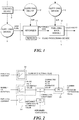
- FIG. 1 is a diagram illustrating an overall structure of the fuel-cell power generation system.
- the fuel-cell power generation system includes a fluid processing device 1, a supplying device 2 that supplies the fluid to the fluid processing device 1, a control device 3 that controls the flow rate of the fluid by controlling the operation quantity of the supplying device 2, and a sensor 4 provided in the fluid processing device 1, and measures a status quantity, that is an object to be monitored, of the fluid processing device 1 or of the interior thereof.
- the fluid processing device 1 processes the fluid, and in this embodiment, corresponds to the reformer 11, and the fuel-cell body 12.
- the reformer 11 has the raw fuel supplied thereto, produces a hydrogen-rich reformed gas, and supplies this gas to the fuel-cell body 12.
- the reformer 11 includes a desulfurization device that desulfurizes the raw fuel, a reforming device that has therein a burner chamber, reforms the fuel that has undergone the desulfurization and produces hydrogen, a CO transforming device that decreases the CO concentration in the reformed gas obtained from the reforming device by a CO transforming reaction (shift reaction), and a CO removing device that removes CO from the reformed gas obtained from the CO transforming device.
- the fuel-cell body 12 supplies, to the fuel electrode and the oxidizer electrode respectively, the hydrogen-rich reformed gas, and air, and generates electromotive force.
- the sensor 4 is provided in the fluid processing device 1 subjected to monitoring, and measures the status quantity that is an object to be monitored.
- this sensor 4 is provided at the reformer 11 or inside the reformer 11.
- Example sensors 4 are a thermometer and a voltmeter.
- the sensor 4 is a thermometer, and measures the temperature of the burner chamber in the reformer 11 or the temperature of a reforming catalyst layer.
- the status quantity of the object to be monitored is the temperature in the CO removing device when the object to be monitored is the CO removing device, and is the output voltage by the fuel-cell body 12 when the object to be monitored is the fuel-cell body 12.
- the supplying device 2 supplies the fluid to the reformer 11 or the fuel-cell body 12. Supplied to the reformer 11 are the raw fuel and air, while supplied to the fuel-cell body 12 is air.
- the supplying device 2 includes, for example, an raw-fuel supplying device that supplies the raw fuel to the desulfurization device, an air supplying device that supplies air to the reforming device, an air supplying device that supplies air to the piping between the CO transforming device and the CO removing device, and an air supplying device that supplies air to the oxidizer electrode of the fuel-cell body 12.
- Example raw fuels supplied by the raw-fuel supplying device are natural gas, liquefied petroleum gas (LPG), and city gas, and may be any gas applied to enable the fuel-cell power generation system to generate power.
- LPG liquefied petroleum gas
- the supplying device 2 adjusts the flow rate of the supplied fluid based on the operation quantity.
- Example supplying devices 2 are a diaphragm-type blower, and a flow-rate adjusting valve that has the open level of the adjusting valve as the operation quantity.
- the following explanation will be given of an example case in which the supplying device 2 is a blower.
- the control device 3 comprehensively controls the overall action of the fuel-cell power generation system, and mainly controls the operation quantity of the supplying device 2, thereby controlling the flow rate of the fluid supplied by the supplying device 2.
- the supplying device 2 is a blower
- the supplied flow rate is adjusted by controlling the number of rotation.
- the control device 3 controls the operation quantity of the supplying device 2 in a way that the status quantity obtained by the sensor 4 becomes a preset status quantity value at the stage of an initial activation, at the time of factory acceptance test, after installation, or after maintenance.
- the number of rotation of the blower is controlled in a way that the reformer temperature follows the reformer-temperature set value.
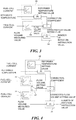
- FIG. 2 is a diagram illustrating a structure of the control device 3 according to this embodiment.
- the control device 3 includes an estimated value calculating unit 31 that calculates a flow rate estimated value which is the flow rate estimated based on the operation quantity of the supplying device 2, a setting value calculating unit 32 that calculates the flow rate setting value for the supplying device 2 based on the correspondence between a current of the fuel-cell body 12 and the necessary fluid flow rate for obtaining such current, an estimated value correcting unit 33 that corrects the flow rate estimated value, a following unit 34 that calculates the operation quantity instruction value for the supplying device 2 in a way that the flow rate estimated value corrected by the estimated value correcting unit 33 follows the flow rate setting value, and an unillustrated memory unit that stores various correspondence beforehand.
- the estimated value calculating unit 31 calculates the flow rate estimated value based on the correspondence between the operation quantity of the supplying device 2 and the fluid flow rate supplied based on the operation quantity.
- the estimated value correcting unit 33 calculates a correction coefficient for the status quantity measured by the sensor 4 to follow the status quantity setting value. More specifically, the estimated value correcting unit 33 performs a PI control based on the deviation between the measured reformer temperature, and a reformer temperature setting value that is obtained from the correspondence between the reformer temperature and the power generation amount by the fuel-cell body 12, to calculate the correction coefficient. Next, the estimated value correcting unit 33 multiplies the flow rate estimated value by the calculated correction coefficient, and corrects the flow rate estimated value.
- the current or the voltage of the fuel-cell body 12 may be applied.
- a proportional control or a PID control may be applied.
- the memory unit stores, in advance, all correspondences explained in this specification.
- the control device 3 adjusts the correction coefficient calculated by the estimated value correcting unit 33 to fall within a predetermined range.
- An example range of the correction coefficient for the supplied flow rate is between 0.98 and 1.02.
- the range of the correction coefficient can be designed and changed as appropriate.
- the control device 3 suspends the system operation.
- the control device 3 controls the operation quantity of the supplying device 2 in a way that the correction coefficient falls within the predetermined range.
- the supplying device 2 has an individual difference, and there is a gap between the correspondence between the operation quantity and the supplied flow rate according to the embodiment, and the correspondence between the operation quantity and the supplied flow rate at the actually installed supplying device 2.
- This gap appears as a deviation between the reformer temperature and the reformer temperature setting value.
- the estimated value correcting unit 33 corrects the flow rate estimated value.
- the cause of the deviation between the reformer temperature and the reformer temperature setting value is not limited to the individual difference of the supplying device 2, and may be a difference in the pressure loss of fluid in the system, and the individual difference of the flowmeter, etc., and those errors are also corrected by the estimated value correcting unit 33.
- the estimated value correcting unit 33 has obtained the reformer temperature setting value beforehand based on the correspondence between the current of the fuel-cell body 12 and the reformer temperature.
- the following procedure is merely an example, and the sequence may be changed as appropriate.
- the above (1) to (5) actions are performed at a stage of initial activation, at the time of factory acceptance test, after installation, or after maintenance.
- the subsequent correction coefficient can be set to 1.0.
- the control device 3 suspends the system operation. After the operation is suspended, when it is confirmed that there is no fuel leakage, the number of rotation of the supplying device 2 is controlled in a way that the correction coefficient falls within the predetermined range.
- the cause of the correction value reaching the upper limit is not always limited to a fuel leakage. That is, although the setting value is given based on the estimated calorific value of the fuel, when the calorific value keenly changes, for example when the fuel that has a low calorific value is supplied under a condition at which it is expected that the fuel which has a large calorific value is being supplied, since there is a relationship between the power generation amount and the calorific value of the fuel, it is necessary to supply more fuel in order to achieve the necessary power generation amount, and therefore the correction coefficient may reach the upper limit value. According to this embodiment, such case can be addressed, and thus the necessary power generation amount is ensured.
- the second embodiment employs the same basic structure as that of the first embodiment. In the following explanation, only the difference from the first embodiment will be explained, and the same reference numeral will be given to the same element as that of the first embodiment, and the detailed explanation will not be repeated.
- an unillustrated flowmeter is provided to the supplying device 2.
- the flowmeter is provided at the piping between the raw fuel supplying device and the reformer 11.
- a measured value which is a flow rate supplied by the supplying device measured by the flowmeter, is applied for the control by the control device 3.
- FIG. 3 is a diagram illustrating a structure of the control device 3 according to the second embodiment.
- the control device 3 of this embodiment includes the setting value calculating unit 32, a setting value correcting unit 35 that corrects the flow rate setting value, and a following unit 36 that calculates the operation quantity instruction value for the supplying device 2 in a way that the flow rate supplied by the supplying device 2 follows the flow rate setting value corrected by the setting value correcting unit 35.
- the setting value correcting unit 35 calculates the correction coefficient that causes the status quantity measured by the sensor 4 to follow the status quantity setting value. More specifically, the setting value correcting unit 35 performs a PI control based on the deviation between the measured reformer temperature and the reformer temperature setting value obtained from the correspondence between the reformer temperature and the power generation amount by the fuel-cell body 12, thereby calculating the correction coefficient. In addition, the setting value correcting unit 35 multiplies the flow rate setting value by the calculated correction coefficient, thereby correcting the flow rate setting value. Instead of the power generation amount in the above correspondence, the current or the voltage of the fuel-cell body 12 may be applied. Note that instead of the PI control, a proportional control or a PID control may be applied.
- the control device 3 adjusts the correction coefficient calculated by the setting value correcting unit 35 to fall within a predetermined range.
- An example range of the correction coefficient for the supplied flow rate is between 0.98 and 1.02 or between 0.8 and 1.2.
- the range of the correction coefficient can be designed and changed as appropriate. When the correction coefficient exceeds the predetermined range, the system operation is suspended. This is because there is a possibility that some kind of defect like a fuel leakage is occurring.
- the following unit 36 calculates the operation quantity instruction value for the supplying device 2 in a way that the flow rate of the supplying device 2 measured by the flowmeter follows the flow rate setting value corrected by the setting value correcting unit 35.
- the setting value correcting unit 35 corrects the flow rate setting value.
- the cause of the deviation between the reformer temperature and the reformer temperature setting value is not limited to the individual difference of the supplying device 2, and may be a difference in the pressure loss of fluid in the system, the individual difference of the flowmeter provided to the supplying device 2, and the calorific value of the supplied fuel, etc., and those errors are also corrected by the estimated value correcting unit 33.
- the setting value correcting unit 35 has obtained the reformer temperature setting value beforehand based on the correspondence between the current of the fuel-cell body 12 and the reformer temperature.
- the following procedure is merely an example, and the sequence may be changed as appropriate.
- the above (1) to (5) actions are performed at a stage of initial activation, at the time of factory acceptance test, after installation, or after maintenance.
- the subsequent correction coefficient can be set to be 1.0.
- the control device 3 suspends the system operation. After the operation is suspended, when it is confirmed that there is no fuel leakage, the number of rotation of the supplying device 2 is controlled in such way that the correction coefficient falls within the predetermined range.
- the control device 3 includes the setting value calculating unit 32 that calculates the flow rate setting value for the supplying device 2 based on the correspondence between the current of the fuel-cell body 12 and the necessary fluid flow rate for obtaining this current, the setting value correcting unit 35 that corrects the flow rate setting value, and the following 36 that calculates the operation quantity instruction value for the supplying device 2 in a way that the supplied flow rate by the supplying device 2 follows the flow rate setting value corrected by the setting value correcting unit 35.
- the setting value correcting unit 35 calculates the correction coefficient that causes the status quantity measured by the sensor 4 to follow the status quantity setting value, and the flow rate setting value is multiplied by the correction value for correction.
- the flow rate setting value is corrected, and thus the variabilities are corrected.
- the correction is performed on the flow rate setting value at the initial stage like at a stage of initial activation, at the time of factory acceptance test, after installation, or after maintenance, the correction is not made during the operation involving the error originating from the individual difference.
- the status quantity is corrected as explained above, the cause of error before the time point at which the status quantity becomes the status quantity obtained by the sensor 4 can be eliminated, and thus a stable operation can be achieved.
- the third embodiment employs the same basic structure as that of the second embodiment. In the following explanation, only the difference from the second embodiment will be explained, and the same reference numeral will be given to the same element as that of the second embodiment, and the detailed explanation will not be repeated.
- the fluid is a fuel.
- Example fuels are a city gas (13A fuel), and a liquefied petroleum gas (LPG) . Those fuels have different calorific values.
- FIG. 4 is a diagram illustrating a structure of the control device 3 according to this embodiment.
- the control device 3 of this embodiment includes a plurality of the setting value calculating units 32, and changing device 37 for changing the flow rate setting value in accordance with the calorific value of the fuel.
- the setting value calculating unit 32 has a different correspondence between the current of the fuel-cell body 12 and the necessary fuel flow rate for obtaining this current. This is because the necessary fuel flow rate differs when the calorific value of the fuel differs.
- the changing device 37 changes, for example, the connection to the plurality of the setting value calculating units 32.
- An example change by the changing device 37 is as follows.
- the object to be monitored is the reformer 11, the object may be the fuel-cell body 12.
- the status quantity, which is an object to be monitored is the output voltage by the fuel-cell body 12, and the sensor 4 is a voltage meter.
- the flow rate estimated value may be corrected like the first embodiment, or the flow rate setting value may be corrected like the second and third embodiments.
Landscapes
- Life Sciences & Earth Sciences (AREA)
- Engineering & Computer Science (AREA)
- Manufacturing & Machinery (AREA)
- Sustainable Development (AREA)
- Sustainable Energy (AREA)
- Chemical & Material Sciences (AREA)
- Chemical Kinetics & Catalysis (AREA)
- Electrochemistry (AREA)
- General Chemical & Material Sciences (AREA)
- Fuel Cell (AREA)
Abstract
Description
- Embodiments of the present disclosure relate to a fuel-cell power generation system.
- Fuel cells are classified into various types depending on, for example, the difference of electrolyte, and solid polymer electrolyte fuel cells using a solid polymer electrolyte film as an electrolyte are suitable for applications such as a small co-generation system covering general household applications, and a power source for an electric vehicle in view of the low-temperature action performance and the high-output density, etc., and such fuel cells are types that is nowadays rapidly increasing the market size.
- As for fuel-cell power generation systems including such solid polymer electrolyte fuel cell, in the case of, for example, a stationary small co-generation system for a general household application, this system includes a reformer, a fuel-cell body, an electricity control device, and a heat utilization system. The reformer produces a hydrogen containing gas from a hydrocarbon fuel represented by, for example, a city gas or an LPG. A fuel cell stack supplies, to a fuel electrode and an oxidizer electrode respectively to generate electromotive force, a hydrogen rich gas that contains H2 as a main component, and CO2, CO, and N2 produced as a surplus gas produced by a CO shift transformer and a CO select oxidizer, , and ambient air. In addition, the electricity control device supplies, to an external load, the electric energy generated by the fuel cell stack, and the heat utilization system collects heat generated by power generation.
- Patent Document 1:
JP 2003-157871 A - Conventionally, with respect to fuel-cell power generation systems, the reformer and the fuel-cell body are provided with a supplying device that supplies an raw fuel and air necessary for power generation, and a flowmeter that measures a supply flow rate in order to obtain the necessary power generation amount. This flowmeter monitors the supply flow rate by the supplying device, and the supply flow rate is adjusted as necessary.
- However, the supplying device and the flowmeter have an individual difference, having variability in the characteristics. In addition, a pressure-loss factor varies depending on the installation environment of the fuel-cell power generation system. As a specific example case for the supplying device, the supplying device has a correspondence between the operation quantity and the fluid flow rate supplied based on the operation quantity, but this correspondence varies for each supplying device. Hence, when there is a gap in the correspondence that is a reference, the necessary flow rate is not supplied even with the same operation quantity, and the necessary power generation amount is not achieved. Hence, it is necessary to perform correction and to adjust the operation quantity. When, however, the correction is made with the reference correspondence still containing an error, such correction contains an error, and the system operation becomes unstable.
- An objective of the present disclosure is to provide a fuel-cell power generation system which is capable of correcting the individual difference and variability of device and facility, and is capable of stably operating.
- A fuel-cell power generation system according to an embodiment of the present disclosure includes a fluid processing device including a reformer or a fuel-cell body, a supplying device supplying a fluid to the fluid processing device, a control device controlling a flow rate of the fluid by controlling an operation quantity of the supplying device, and a sensor provided in the fluid processing device, and measuring a status quantity, that is an object to be monitored, of the fluid processing device or of an interior of the fluid processing device. The control device controls the operation quantity in a way that the status quantity obtained by the sensor becomes a preset status quantity setting value at a stage of initial activation, at a time of factory acceptance test, after installation, or after maintenance.
-
-
FIG. 1 is a diagram illustrating an overall structure of a fuel-cell power generation system according to a first embodiment; -
FIG. 2 is a diagram illustrating a structure of a control device according to the first embodiment; -
FIG. 3 is a diagram illustrating a structure of a control device according to a second embodiment; and -
FIG. 4 is a diagram illustrating a structure of a control device according to a third embodiment. - A fuel-cell power generation system according to this embodiment will be explained below with reference to
FIGs. 1 and 2. FIG. 1 is a diagram illustrating an overall structure of the fuel-cell power generation system. - The fuel-cell power generation system includes a
fluid processing device 1, a supplyingdevice 2 that supplies the fluid to thefluid processing device 1, acontrol device 3 that controls the flow rate of the fluid by controlling the operation quantity of thesupplying device 2, and asensor 4 provided in thefluid processing device 1, and measures a status quantity, that is an object to be monitored, of thefluid processing device 1 or of the interior thereof. - The
fluid processing device 1 processes the fluid, and in this embodiment, corresponds to thereformer 11, and the fuel-cell body 12. Thereformer 11 has the raw fuel supplied thereto, produces a hydrogen-rich reformed gas, and supplies this gas to the fuel-cell body 12. Thereformer 11 includes a desulfurization device that desulfurizes the raw fuel, a reforming device that has therein a burner chamber, reforms the fuel that has undergone the desulfurization and produces hydrogen, a CO transforming device that decreases the CO concentration in the reformed gas obtained from the reforming device by a CO transforming reaction (shift reaction), and a CO removing device that removes CO from the reformed gas obtained from the CO transforming device. The fuel-cell body 12 supplies, to the fuel electrode and the oxidizer electrode respectively, the hydrogen-rich reformed gas, and air, and generates electromotive force. - The
sensor 4 is provided in thefluid processing device 1 subjected to monitoring, and measures the status quantity that is an object to be monitored. In this embodiment, thissensor 4 is provided at thereformer 11 or inside thereformer 11.Example sensors 4 are a thermometer and a voltmeter. In this embodiment, thesensor 4 is a thermometer, and measures the temperature of the burner chamber in thereformer 11 or the temperature of a reforming catalyst layer. Note that the status quantity of the object to be monitored is the temperature in the CO removing device when the object to be monitored is the CO removing device, and is the output voltage by the fuel-cell body 12 when the object to be monitored is the fuel-cell body 12. - The supplying
device 2 supplies the fluid to thereformer 11 or the fuel-cell body 12. Supplied to thereformer 11 are the raw fuel and air, while supplied to the fuel-cell body 12 is air. The supplyingdevice 2 includes, for example, an raw-fuel supplying device that supplies the raw fuel to the desulfurization device, an air supplying device that supplies air to the reforming device, an air supplying device that supplies air to the piping between the CO transforming device and the CO removing device, and an air supplying device that supplies air to the oxidizer electrode of the fuel-cell body 12. Example raw fuels supplied by the raw-fuel supplying device are natural gas, liquefied petroleum gas (LPG), and city gas, and may be any gas applied to enable the fuel-cell power generation system to generate power. - The supplying
device 2 adjusts the flow rate of the supplied fluid based on the operation quantity.Example supplying devices 2 are a diaphragm-type blower, and a flow-rate adjusting valve that has the open level of the adjusting valve as the operation quantity. In this embodiment, the following explanation will be given of an example case in which the supplyingdevice 2 is a blower. - The
control device 3 comprehensively controls the overall action of the fuel-cell power generation system, and mainly controls the operation quantity of the supplyingdevice 2, thereby controlling the flow rate of the fluid supplied by the supplyingdevice 2. When the supplyingdevice 2 is a blower, the supplied flow rate is adjusted by controlling the number of rotation. Thecontrol device 3 controls the operation quantity of the supplyingdevice 2 in a way that the status quantity obtained by thesensor 4 becomes a preset status quantity value at the stage of an initial activation, at the time of factory acceptance test, after installation, or after maintenance. In this embodiment, the number of rotation of the blower is controlled in a way that the reformer temperature follows the reformer-temperature set value. -
FIG. 2 is a diagram illustrating a structure of thecontrol device 3 according to this embodiment. - The
control device 3 according to this embodiment includes an estimatedvalue calculating unit 31 that calculates a flow rate estimated value which is the flow rate estimated based on the operation quantity of the supplyingdevice 2, a settingvalue calculating unit 32 that calculates the flow rate setting value for the supplyingdevice 2 based on the correspondence between a current of the fuel-cell body 12 and the necessary fluid flow rate for obtaining such current, an estimatedvalue correcting unit 33 that corrects the flow rate estimated value, a followingunit 34 that calculates the operation quantity instruction value for the supplyingdevice 2 in a way that the flow rate estimated value corrected by the estimatedvalue correcting unit 33 follows the flow rate setting value, and an unillustrated memory unit that stores various correspondence beforehand. - The estimated
value calculating unit 31 calculates the flow rate estimated value based on the correspondence between the operation quantity of the supplyingdevice 2 and the fluid flow rate supplied based on the operation quantity. The estimatedvalue correcting unit 33 calculates a correction coefficient for the status quantity measured by thesensor 4 to follow the status quantity setting value. More specifically, the estimatedvalue correcting unit 33 performs a PI control based on the deviation between the measured reformer temperature, and a reformer temperature setting value that is obtained from the correspondence between the reformer temperature and the power generation amount by the fuel-cell body 12, to calculate the correction coefficient. Next, the estimatedvalue correcting unit 33 multiplies the flow rate estimated value by the calculated correction coefficient, and corrects the flow rate estimated value. Instead of the power generation amount in the above correspondence, the current or the voltage of the fuel-cell body 12 may be applied. Note that instead of the PI control, a proportional control or a PID control may be applied. The memory unit stores, in advance, all correspondences explained in this specification. - The
control device 3 adjusts the correction coefficient calculated by the estimatedvalue correcting unit 33 to fall within a predetermined range. An example range of the correction coefficient for the supplied flow rate is between 0.98 and 1.02. The range of the correction coefficient can be designed and changed as appropriate. When the correction coefficient exceeds the predetermined range, the system operation is suspended. This is because there is a possibility that some kind of defect like a fuel leakage is occurring. For example, when the correction coefficient reaches a preset upper limit value, thecontrol device 3 suspends the system operation. In addition, when the correction coefficient reaches the preset upper limit value and it is confirmed that there is no fuel leakage, thecontrol device 3 controls the operation quantity of the supplyingdevice 2 in a way that the correction coefficient falls within the predetermined range. - An action of the fuel-cell power generation system according to this embodiment will be explained. First of all, the principle of this system will be explained. There is a correspondence between the reformer temperature and the power generation amount by the fuel-
cell body 12, and the reformer temperature setting value is set as appropriate in accordance with the desired power generation amount. In addition, the reformer temperature has a correspondence with the supplied flow rate by the supplyingdevice 2, and there is also a correspondence between the supplied flow rate by the supplyingdevice 2 and the operation quantity of the supplyingdevice 2. Accordingly, by controlling the operation quantity of the supplyingdevice 2 in a way that the reformer temperature becomes the reformer temperature setting value, a desired power generation amount. - However, the supplying
device 2 has an individual difference, and there is a gap between the correspondence between the operation quantity and the supplied flow rate according to the embodiment, and the correspondence between the operation quantity and the supplied flow rate at the actually installed supplyingdevice 2. This gap appears as a deviation between the reformer temperature and the reformer temperature setting value. In this embodiment, in order to correct such gap, the estimatedvalue correcting unit 33 corrects the flow rate estimated value. The cause of the deviation between the reformer temperature and the reformer temperature setting value is not limited to the individual difference of the supplyingdevice 2, and may be a difference in the pressure loss of fluid in the system, and the individual difference of the flowmeter, etc., and those errors are also corrected by the estimatedvalue correcting unit 33. - Next, the action of this system will be explained. It is on the premise that the estimated
value correcting unit 33 has obtained the reformer temperature setting value beforehand based on the correspondence between the current of the fuel-cell body 12 and the reformer temperature. The following procedure is merely an example, and the sequence may be changed as appropriate. - (1) First, the estimated
value calculating unit 31 calculates, based on the correspondence between the operation quantity (number of rotation) of the supplyingdevice 2 and the supplied flow rate at this operation quantity, and based on the present operation quantity, the supplied flow rate estimated value. - (2) Next, the
sensor 4 measures the temperature of thereformer 11, and the estimatedvalue correcting unit 33 obtains the deviation between the measured reformer temperature and the reformer temperature setting value, and calculates the correction coefficient in a way that the deviation is corrected, that is, the deviation becomes zero. Subsequently, the estimatedvalue correcting unit 33 multiplies the flow rate estimated value by the calculated correction coefficient, thereby calculating the corrected flow rate estimated value. - (3) In addition, the setting
value calculating unit 32 calculates the flow rate setting value for the supplyingdevice 2 based on the correspondence between the current of the fuel-cell body 12 and the necessary fluid flow rate for obtaining this current. - (4) Subsequently, the following
unit 34 receives the corrected flow rate estimated value and the flow rate setting value as input, and calculates, by the PI control, the instruction value for the number of rotation in order to cause the reformer temperature to be the reformer temperature setting value. - (5) The
control device 3 sets the operation quantity (number of rotation) of the supplyingdevice 2 to be the calculated instruction value for the number of rotation, thereby matching the reformer temperature with the reformer temperature setting value. - The above (1) to (5) actions are performed at a stage of initial activation, at the time of factory acceptance test, after installation, or after maintenance. By performing the correction on the flow rate estimated value at such initial stage, when there is no change in the status of the system, the subsequent correction coefficient can be set to 1.0.
- A specific example of adjusting the correction coefficient will be explained. In the case the correction coefficient calculated by the estimated
value correcting unit 33 is 1.2, when the operation quantity of the supplyingdevice 2 is adjusted in accordance with the operation quantity instruction value calculated by the followingunit 34, the reformer temperature becomes consistent with the reformer temperature setting value. In this way, the correction coefficient to be calculated after the feedback that causes the reformer temperature to be consistent with the reformer temperature setting value becomes 1.0. The same is true of the case in which the correction coefficient becomes lower than 1.0. As explained above, the correction coefficient falls within the predetermined range. - On the other hand, when the correction coefficient reaches the preset upper limit value, the
control device 3 suspends the system operation. After the operation is suspended, when it is confirmed that there is no fuel leakage, the number of rotation of the supplyingdevice 2 is controlled in a way that the correction coefficient falls within the predetermined range. -
- (1) The fuel-cell power generation system according to this embodiment includes the
fluid processing device 1 having thereformer 11 or the fuel-cell body 12, the supplyingdevice 2 that supplies the fluid to thefluid processing device 1, thecontrol device 3 that controls the fluid flow rate by controlling the operation quantity of the supplyingdevice 2, and thesensor 4 which is provided in thefluid processing device 1, and measures the status quantity, that is the object to be monitored, of thefluid processing device 1 or of the interior of thefluid processing device 1. Thecontrol device 3 controls the operation quantity at a stage of initial activation, at the time of factory acceptance test, after installation, or after maintenance in a way that the obtained status quantity by thesensor 4 becomes the status quantity setting value.
Hence, a stable system operation is achieved. That is, at a stage of initial activation, at the time of factory acceptance test, after installation, or after maintenance, each device and facility in the system is inspected at least one time, and thus it can be considered that there is no fuel leakage in the fuel-cell power generation system. Hence, the cause of the deviation between the measured status quantity and the setting value may originate from other than the fuel leakage such as the variability in characteristics of each device, etc., and by performing the correction at the initial stage, even if the individual difference of the supplying device varies and the pressure loss factor varies, etc., those variabilities can be eliminated. Hence, instable operation by the operation that involves the error in individual difference can be prevented, and thus a stable operation can be achieved. - (2) The
control device 3 includes the estimatedvalue calculating unit 31 that calculates the flow rate estimated value which is the flow rate estimated from the operation quantity of the supplyingdevice 2, the settingvalue calculating unit 32 that calculates the flow rate setting value for the supplyingdevice 2 based on the correspondence between the current of the fuel-cell body 12 and the necessary fluid flow rate for obtaining the current, the estimatedvalue correcting unit 33 that corrects the flow rate estimated value, and the followingunit 34 that calculates the operation quantity instruction value for the supplyingdevice 2 in a way that the flow rate estimated value corrected by the estimatedvalue correcting unit 33 follows the flow rate setting value. The estimatedvalue correcting unit 33 calculates the correction coefficient that causes the status quantity measured by thesensor 4 to follow the status quantity setting value, and multiplies the flow rate estimated value by the correction coefficient for the correction.
Hence, the flow rate estimated value is corrected, and thus the characteristic variability originating from the individual difference of the supplyingdevice 2 and he individual difference of the flowmeter that measures the supplied flow rate can be corrected. In addition, since the precise estimation of the flow rate supplied by the supplyingdevice 2 is enabled, it is unnecessary to measure this supplied flow rate by a flowmeter. Hence, the flowmeter can be eliminated, and the costs can be consequently reduced. In particular, according to the fuel-cell power generation system, since there are multiple locations needing a supply of fluid, such as the supply of the raw fuel to thereformer 11, the supply of air to the burner chamber in thereformer 11, the supply of air to remove CO in thereformer 11, and the supply of air to the fuel-cell body 12, the costs can be reduced as much according to this embodiment because of the elimination of a flowmeter. - (3) The
control device 3 adjusts the correction coefficient to fall within the predetermined range. This achieves a stable operation. - (4) The system is suspended when the correction coefficient reaches the preset upper limit value. This enables a safe system operation. That is, when, for example, a fuel leakage is occurring between the
reformer 11 and the fuel-cell body 12, if the correction coefficient is increased, the leaking flow rate also increases. In contrast, by setting the upper limit value for the correction coefficient, when the correction coefficient reaches the upper limit value, a determination can be made that there is a fuel leakage. Hence, the system can be suspended, and the continuation of the defective status can be prevented, thereby achieving a safe operation. - (5) The
control device 3 controls the operation quantity of the supplyingdevice 2 in a way that the correction coefficient falls within the predetermined range when the correction coefficient reaches the preset upper limit value if it is confirmed that there is no fuel leakage. - Hence, even if the calorific value of the supplied fuel keenly changes, this can be addressed. That is, the cause of the correction value reaching the upper limit is not always limited to a fuel leakage. That is, although the setting value is given based on the estimated calorific value of the fuel, when the calorific value keenly changes, for example when the fuel that has a low calorific value is supplied under a condition at which it is expected that the fuel which has a large calorific value is being supplied, since there is a relationship between the power generation amount and the calorific value of the fuel, it is necessary to supply more fuel in order to achieve the necessary power generation amount, and therefore the correction coefficient may reach the upper limit value. According to this embodiment, such case can be addressed, and thus the necessary power generation amount is ensured.
- An explanation will be given of a second embodiment with reference to
FIG. 3 . The second embodiment employs the same basic structure as that of the first embodiment. In the following explanation, only the difference from the first embodiment will be explained, and the same reference numeral will be given to the same element as that of the first embodiment, and the detailed explanation will not be repeated. - In this embodiment, an unillustrated flowmeter is provided to the supplying
device 2. In the case of, for example, the raw fuel supplying device, the flowmeter is provided at the piping between the raw fuel supplying device and thereformer 11. In this embodiment, since the flowmeter is provided, instead of the flow rate estimated value, a measured value, which is a flow rate supplied by the supplying device measured by the flowmeter, is applied for the control by thecontrol device 3. -
FIG. 3 is a diagram illustrating a structure of thecontrol device 3 according to the second embodiment. Thecontrol device 3 of this embodiment includes the settingvalue calculating unit 32, a settingvalue correcting unit 35 that corrects the flow rate setting value, and a followingunit 36 that calculates the operation quantity instruction value for the supplyingdevice 2 in a way that the flow rate supplied by the supplyingdevice 2 follows the flow rate setting value corrected by the settingvalue correcting unit 35. - The setting
value correcting unit 35 calculates the correction coefficient that causes the status quantity measured by thesensor 4 to follow the status quantity setting value. More specifically, the settingvalue correcting unit 35 performs a PI control based on the deviation between the measured reformer temperature and the reformer temperature setting value obtained from the correspondence between the reformer temperature and the power generation amount by the fuel-cell body 12, thereby calculating the correction coefficient. In addition, the settingvalue correcting unit 35 multiplies the flow rate setting value by the calculated correction coefficient, thereby correcting the flow rate setting value. Instead of the power generation amount in the above correspondence, the current or the voltage of the fuel-cell body 12 may be applied. Note that instead of the PI control, a proportional control or a PID control may be applied. - The
control device 3 adjusts the correction coefficient calculated by the settingvalue correcting unit 35 to fall within a predetermined range. An example range of the correction coefficient for the supplied flow rate is between 0.98 and 1.02 or between 0.8 and 1.2. The range of the correction coefficient can be designed and changed as appropriate. When the correction coefficient exceeds the predetermined range, the system operation is suspended. This is because there is a possibility that some kind of defect like a fuel leakage is occurring. - A specific example of adjusting the correction coefficient will be explained. In the case the correction coefficient calculated by the setting
value correcting unit 35 is 1.2, when the operation quantity of the supplyingdevice 2 is adjusted in accordance with the operation quantity instruction value calculated by the followingunit 36, the reformer temperature becomes consistent with the reformer temperature setting value. In this way, the correction coefficient to be calculated after the feedback that causes the reformer temperature to be consistent with the reformer temperature setting value becomes 1.0. As explained above, the correction coefficient falls within the predetermined range. - The following
unit 36 calculates the operation quantity instruction value for the supplyingdevice 2 in a way that the flow rate of the supplyingdevice 2 measured by the flowmeter follows the flow rate setting value corrected by the settingvalue correcting unit 35. - An action of the fuel-cell power generation system according to this embodiment will be explained. The basic action is the same as that of the first embodiment, and only the difference will be explained.
- According to this system, in order to correct a gap between the reformer temperature and the reformer temperature setting value, the setting
value correcting unit 35 corrects the flow rate setting value. The cause of the deviation between the reformer temperature and the reformer temperature setting value is not limited to the individual difference of the supplyingdevice 2, and may be a difference in the pressure loss of fluid in the system, the individual difference of the flowmeter provided to the supplyingdevice 2, and the calorific value of the supplied fuel, etc., and those errors are also corrected by the estimatedvalue correcting unit 33. - Next, an explanation will be given of the action of this system. It is on the premise that the setting
value correcting unit 35 has obtained the reformer temperature setting value beforehand based on the correspondence between the current of the fuel-cell body 12 and the reformer temperature. The following procedure is merely an example, and the sequence may be changed as appropriate. - (1) First, the flowmeter measures the flow rate supplied by the supplying
device 2. - (2) The setting
value calculating unit 32 calculates the flow rate setting value for the supplyingdevice 2 based on the correspondence between the current of the fuel-cell body 12 and the necessary fluid flow rate for obtaining the current. - (3) The
sensor 4 measures the temperature of thereformer 11, the settingvalue correcting unit 35 obtains the deviation between the measured reformer temperature and the reformer temperature setting value, and the correction coefficient is calculated in a way that the deviation is corrected, that is, the deviation becomes zero. In addition, the settingvalue correcting unit 35 multiplies the flow rate setting value by the calculated correction coefficient, and calculates the corrected flow rate setting value. - (4) Next, the following
unit 36 receives the corrected flow volume setting value and the flow volume measured value input, and calculates, through the PI control, the instruction value for the number of rotation that causes the reformer temperature to be the reformer temperature setting value. - (5) The
control device 3 causes the operation quantity (number of rotation) of the supplyingdevice 2 to be the calculated instruction value for the number of rotation, and thus the reformer temperature becomes consistent with the reformer temperature setting value. - The above (1) to (5) actions are performed at a stage of initial activation, at the time of factory acceptance test, after installation, or after maintenance. By performing the correction on the flow rate estimated value at such initial stage, when there is no change in the status of the system, the subsequent correction coefficient can be set to be 1.0.
- A specific example of adjusting the correction coefficient will be explained. In the case the correction coefficient calculated by the setting
value correcting unit 35 is 1.2, when the operation quantity of the supplyingdevice 2 is adjusted in accordance with the operation quantity instruction value calculated by the followingunit 36, the reformer temperature becomes consistent with the reformer temperature setting value. In this way, the correction coefficient to be calculated after the feedback that causes the reformer temperature to be consistent with the reformer temperature setting value becomes 1.0. The same is true of the case in which the correction coefficient becomes lower than 1.0. As explained above, the correction coefficient falls within the predetermined range. - On the other hand, when the correction coefficient reaches the preset upper limit value, the
control device 3 suspends the system operation. After the operation is suspended, when it is confirmed that there is no fuel leakage, the number of rotation of the supplyingdevice 2 is controlled in such way that the correction coefficient falls within the predetermined range. - According to this embodiment, the
control device 3 includes the settingvalue calculating unit 32 that calculates the flow rate setting value for the supplyingdevice 2 based on the correspondence between the current of the fuel-cell body 12 and the necessary fluid flow rate for obtaining this current, the settingvalue correcting unit 35 that corrects the flow rate setting value, and the following 36 that calculates the operation quantity instruction value for the supplyingdevice 2 in a way that the supplied flow rate by the supplyingdevice 2 follows the flow rate setting value corrected by the settingvalue correcting unit 35. The settingvalue correcting unit 35 calculates the correction coefficient that causes the status quantity measured by thesensor 4 to follow the status quantity setting value, and the flow rate setting value is multiplied by the correction value for correction. - Hence, even if there is a variability in characteristics of the flowmeter, and there is a variability in calorific value of the fuel supplied from the raw fuel supplying device, the flow rate setting value is corrected, and thus the variabilities are corrected. In particular, since correction is performed on the flow rate setting value at the initial stage like at a stage of initial activation, at the time of factory acceptance test, after installation, or after maintenance, the correction is not made during the operation involving the error originating from the individual difference. Hence, a stable system operation can be achieved. Since the status quantity is corrected as explained above, the cause of error before the time point at which the status quantity becomes the status quantity obtained by the
sensor 4 can be eliminated, and thus a stable operation can be achieved. - An explanation will be given of a third embodiment with reference to
FIG. 4 . The third embodiment employs the same basic structure as that of the second embodiment. In the following explanation, only the difference from the second embodiment will be explained, and the same reference numeral will be given to the same element as that of the second embodiment, and the detailed explanation will not be repeated. - In this embodiment, what is focused among the types of the supplying
device 2 is the raw fuel supplying device. Hence, the fluid is a fuel. Example fuels are a city gas (13A fuel), and a liquefied petroleum gas (LPG) . Those fuels have different calorific values. -
FIG. 4 is a diagram illustrating a structure of thecontrol device 3 according to this embodiment. As illustrated inFIG. 4 , thecontrol device 3 of this embodiment includes a plurality of the settingvalue calculating units 32, and changingdevice 37 for changing the flow rate setting value in accordance with the calorific value of the fuel. The settingvalue calculating unit 32 has a different correspondence between the current of the fuel-cell body 12 and the necessary fuel flow rate for obtaining this current. This is because the necessary fuel flow rate differs when the calorific value of the fuel differs. - The changing
device 37 changes, for example, the connection to the plurality of the settingvalue calculating units 32. An example change by the changingdevice 37 is as follows. - (1) When it has been known beforehand that the fuel which has a different calorific value is to be supplied, the connection may be changed beforehand.
- (2) When there is a variability in quality of the fuel to be supplied, the calorific value may change. In this case, when, for example, the predetermined change in calorific value exceeds a predetermined threshold, the flow rate setting value may be changed. The detection on the calorific value is reflected on the correction coefficient for the burner temperature. When, for example, a gas that has a low calorific value is introduced, the correction coefficient for the burner temperature increases, and when a gas that has a high calorific value is introduced, the correction coefficient decreases. It is effective to change the flow rate setting value as explained above when the correction coefficient decreases.
- (3) A threshold may be set to be consistent with the upper limit value and lower limit value of the correction coefficient or within the predetermined range for the correction coefficient, and when the correction coefficient reaches the threshold, a determination may be made that there is a large change in calorific value, and the flow rate setting value may be changed.
- (4) The changing
device 37 may change the flow rate setting value depending on whether the fuel is the city gas or the liquefied petroleum gas. - (5) The changing
device 37 may change the flow rate setting value in accordance with the calorific value of the fuel that is different area by area. -
- (1) According to this embodiment, the fluid supplied by the supplying
device 2 is a fuel, and thecontrol device 3 includes the changingdevice 37 that changes the flow rate setting value in accordance with the calorific value of the fuel. This enables the system to cope with a case in which fuels that have different calorific values are to be supplied. Even if the calorific value of the fuel supplied by the supplyingdevice 2 changes, the system is capable of coping with the change in calorific value of the fuel. - (2) The changing
device 37 changes the flow rate setting value in accordance with whether the type of fuel supplied by the supplyingdevice 2 is the city gas or the liquefied petroleum gas. Hence, even when the type of supplied fuel differs, the necessary supplied flow rate can be supplied appropriately, and thus the system is capable of coping with the case in which the type of fuel differs. - (3) The changing
device 37 changes the flow rate setting value in accordance with the calorific value of the fuel which is different area by area. Hence, even when the calorific value of the fuel supplied via a pipeline differs area by area, the system is capable of coping with the case without a change in the basic structure of the system. When, for example, this system is installed at an area where the calorific value of the supplied fuel differs such as an H-gas supply area where the supplied fuel has a high calorific value, and an L-gas supply area where the supplied fuel has a small calorific value, like in Europe, this system is capable of coping with such difference. - Several embodiments of the present disclosure have been explained above in this specification, but those embodiments are merely presented as examples, and are not intended to the scope of the present disclosure. The above embodiments can be carried out in other various forms, and various omissions, replacements, and modifications can be made without departing from the scope of the present disclosure. Such embodiments and modified forms thereof are within the scope of the present disclosure, and also within the scope of the invention as recited in the appended claims and the equivalent ranges thereto.
- As for other embodiments, although the object to be monitored is the
reformer 11, the object may be the fuel-cell body 12. In this case, the status quantity, which is an object to be monitored, is the output voltage by the fuel-cell body 12, and thesensor 4 is a voltage meter. When the output voltage measured by the voltage meter is inconsistent with the preset output voltage setting value, in order to correct such inconsistency, the flow rate estimated value may be corrected like the first embodiment, or the flow rate setting value may be corrected like the second and third embodiments.
Claims (8)
- A fuel-cell power generation system comprising:a fluid processing device comprising a reformer or a fuel-cell body;a supplying device supplying a fluid to the fluid processing device;a control device controlling a flow rate of the fluid by controlling an operation quantity of the supplying device; anda sensor provided in the fluid processing device, and measuring a status quantity, that is an object to be monitored, of the fluid processing device or of an interior of the fluid processing device,the control device controls the operation quantity in a way that the status quantity obtained by the sensor becomes a preset status quantity setting value at a stage of initial activation, at a time of factory acceptance test, after installation or after maintenance.
- The fuel-cell power generation system according to claim 1, wherein:the control device comprises:an estimated value calculating unit calculating a flow rate estimated value that is a flow rate estimated from the operation quantity of the supplying device;a setting value calculating unit calculating a flow rate setting value for the supplying device based on a correspondence between a current of the fuel-cell body and a necessary fluid flow rate for obtaining the current;an estimated value correcting unit correcting the flow rate estimated value; anda following unit calculating an operation quantity instruction value for the supplying device in a way that the flow rate estimated value corrected by the estimated value correcting unit follows the flow rate setting value, andthe estimated value correcting unit calculates a correction coefficient that causes the status quantity obtained by the sensor to follow the status quantity setting value, and multiplies the flow rate estimated value by the correction coefficient for correction.
- The fuel-cell power generation system according to claim 1, wherein:the control device comprises:a setting value calculating unit calculating a flow rate setting value for the supplying device based on a correspondence between a current of the fuel-cell body and a necessary fluid flow rate for obtaining the current;a setting value correcting unit correcting the flow rate setting value; anda following unit calculating an operation quantity instruction value for the supplying device in a way that the flow rate supplied by the supplying device follows the flow rate setting value corrected by the setting value correcting unit, andthe setting value correcting unit calculates a correction coefficient that causes the status quantity obtained by the sensor to follow the status quantity setting value, and multiplies the flow rate setting value by the correction coefficient for correction.
- The fuel-cell power generation system according to claim 3, wherein:the fluid supplied by the supplying device is a fuel; andthe control device comprises changing device for changing the flow rate setting value in accordance with a calorific value of the fuel.
- The fuel-cell power generation system according to claim 4, wherein the changing device changes the flow rate setting value in accordance with whether the fuel supplied from the supplying device is a city gas or a liquefied petroleum gas.
- The fuel-cell power generation system according to claim 4, wherein the changing device changes the flow rate setting value in accordance with the calorific value of the fuel that is different area by area.
- The fuel-cell power generation system according to any one of claims 1 to 6, wherein the fuel-cell power generation system is suspended when the correction coefficient reaches a preset upper limit value.
- The fuel-cell power generation system according to any one of claims 1 to 7, wherein, when the correction coefficient reaches a preset upper limit value, upon confirming that there is no fuel leakage, the control device controls the operation quantity of the supplying device in a way that the correction coefficient falls within a predetermined range.
Applications Claiming Priority (1)
| Application Number | Priority Date | Filing Date | Title |
|---|---|---|---|
| JP2016168892A JP2018037258A (en) | 2016-08-31 | 2016-08-31 | Fuel cell power generation system |
Publications (1)
| Publication Number | Publication Date |
|---|---|
| EP3291347A1 true EP3291347A1 (en) | 2018-03-07 |
Family
ID=59269951
Family Applications (1)
| Application Number | Title | Priority Date | Filing Date |
|---|---|---|---|
| EP17179166.8A Withdrawn EP3291347A1 (en) | 2016-08-31 | 2017-06-30 | Fuel-cell power generation system comprising initial correction of the flow rate of fluid supplying device |
Country Status (3)
| Country | Link |
|---|---|
| EP (1) | EP3291347A1 (en) |
| JP (1) | JP2018037258A (en) |
| KR (1) | KR102019759B1 (en) |
Cited By (2)
| Publication number | Priority date | Publication date | Assignee | Title |
|---|---|---|---|---|
| CN119050411A (en) * | 2024-08-20 | 2024-11-29 | 上海澄朴科技有限公司 | Method, device, equipment and medium for estimating circulation flow of cooling loop of fuel cell system |
| CN119092757A (en) * | 2024-11-08 | 2024-12-06 | 深圳三环科技有限公司 | Fuel cell control system, control method and storage medium |
Families Citing this family (2)
| Publication number | Priority date | Publication date | Assignee | Title |
|---|---|---|---|---|
| JP7002389B2 (en) * | 2018-03-27 | 2022-02-04 | 大阪瓦斯株式会社 | Fuel cell power generation system |
| JP7531100B2 (en) | 2020-04-30 | 2024-08-09 | パナソニックIpマネジメント株式会社 | Component crimping device and component crimping method |
Citations (4)
| Publication number | Priority date | Publication date | Assignee | Title |
|---|---|---|---|---|
| JP2003157871A (en) | 2001-11-22 | 2003-05-30 | Toshiba Corp | Fuel cell power generation system and control method for fuel cell power generation system |
| JP2008004414A (en) * | 2006-06-23 | 2008-01-10 | Aisin Seiki Co Ltd | Fluid supply amount estimation device and fuel cell system |
| EP2639873A2 (en) * | 2012-03-12 | 2013-09-18 | Aisin Seiki Kabushiki Kaisha | Fuel cell system |
| US20150125769A1 (en) * | 2012-05-11 | 2015-05-07 | Ballard Power Systems Inc. | Method of operating a fuel cell power system |
Family Cites Families (7)
| Publication number | Priority date | Publication date | Assignee | Title |
|---|---|---|---|---|
| JP2000036313A (en) * | 1998-07-21 | 2000-02-02 | Mitsubishi Electric Corp | Phosphoric acid fuel cell power generator |
| JP2002050379A (en) * | 2000-08-04 | 2002-02-15 | Matsushita Electric Ind Co Ltd | Hydrogen production apparatus and operation method thereof |
| JP5198019B2 (en) * | 2007-09-20 | 2013-05-15 | 株式会社東芝 | Fuel cell power generation system and control method thereof |
| JP5167746B2 (en) * | 2007-09-28 | 2013-03-21 | カシオ計算機株式会社 | FUEL CELL SYSTEM AND METHOD FOR OPERATION AND CONTROL OF FUEL CELL SYSTEM |
| JP5606117B2 (en) * | 2010-03-26 | 2014-10-15 | 東芝燃料電池システム株式会社 | Fuel cell power generation system and operation method thereof |
| JP6264125B2 (en) * | 2014-03-20 | 2018-01-24 | アイシン精機株式会社 | Fuel cell system |
| CN106133539A (en) * | 2014-03-26 | 2016-11-16 | 日产自动车株式会社 | Impedance measuring instrument and impedance measuring method |
-
2016
- 2016-08-31 JP JP2016168892A patent/JP2018037258A/en active Pending
-
2017
- 2017-06-27 KR KR1020170081097A patent/KR102019759B1/en not_active Expired - Fee Related
- 2017-06-30 EP EP17179166.8A patent/EP3291347A1/en not_active Withdrawn
Patent Citations (4)
| Publication number | Priority date | Publication date | Assignee | Title |
|---|---|---|---|---|
| JP2003157871A (en) | 2001-11-22 | 2003-05-30 | Toshiba Corp | Fuel cell power generation system and control method for fuel cell power generation system |
| JP2008004414A (en) * | 2006-06-23 | 2008-01-10 | Aisin Seiki Co Ltd | Fluid supply amount estimation device and fuel cell system |
| EP2639873A2 (en) * | 2012-03-12 | 2013-09-18 | Aisin Seiki Kabushiki Kaisha | Fuel cell system |
| US20150125769A1 (en) * | 2012-05-11 | 2015-05-07 | Ballard Power Systems Inc. | Method of operating a fuel cell power system |
Cited By (2)
| Publication number | Priority date | Publication date | Assignee | Title |
|---|---|---|---|---|
| CN119050411A (en) * | 2024-08-20 | 2024-11-29 | 上海澄朴科技有限公司 | Method, device, equipment and medium for estimating circulation flow of cooling loop of fuel cell system |
| CN119092757A (en) * | 2024-11-08 | 2024-12-06 | 深圳三环科技有限公司 | Fuel cell control system, control method and storage medium |
Also Published As
| Publication number | Publication date |
|---|---|
| KR20180025160A (en) | 2018-03-08 |
| KR102019759B1 (en) | 2019-09-10 |
| JP2018037258A (en) | 2018-03-08 |
Similar Documents
| Publication | Publication Date | Title |
|---|---|---|
| Jia et al. | Mitigation strategies for hydrogen starvation under dynamic loading in proton exchange membrane fuel cells | |
| Jensen et al. | Pressurized operation of a planar solid oxide cell stack | |
| Andreasen et al. | Control and experimental characterization of a methanol reformer for a 350 W high temperature polymer electrolyte membrane fuel cell system | |
| Kupecki et al. | Numerical analysis of an SOFC stack under loss of oxidant related fault conditions using a dynamic non-adiabatic model | |
| EP2808298B1 (en) | Method for operating hydrogen generation device and method for operating a fuel cell system | |
| US20170018792A1 (en) | Generation of oxygen depleted air by a fuel cell system | |
| EP3704755A1 (en) | Fuel cell module arrangement with leak recovery and methods of use | |
| KR102019759B1 (en) | Fuel cell power generation system | |
| DK2658021T3 (en) | A method and control device for regulating a fuel cell or fuel cell stack | |
| Andronie et al. | Simplified mathematical model for polarization curve validation and experimental performance evaluation of a PEM fuel cell system | |
| US20130316258A1 (en) | Fuel cell system | |
| CN102792507A (en) | Fuel cell system and method for controlling electric current of same | |
| CN111725545A (en) | A kind of control method, device and FCU of SOFC system | |
| CN110534770A (en) | fuel cell system | |
| WO2018163964A1 (en) | Fuel cell system and fuel cell control program | |
| US20170237095A1 (en) | Fuel cell device and operation control method for fuel cell device | |
| JP6574893B2 (en) | Hydrogen leak prevention system, hydrogen leak prevention method hydrogen production system, power storage system | |
| Harms et al. | Variability and comparability of testing procedures for PEMFC stacks and modules regarding performance aspects | |
| US20190356001A1 (en) | Fuel cell system including wobbe index detector and method of operating same | |
| Horalek et al. | Multiple model predictive control of grid connected solid oxide fuel cell for extending cell life time | |
| Rosli et al. | Reactant Control System for Proton Exchange Membrane Fuel Cell | |
| EP2800185A1 (en) | Fuel cell system and method for operating same | |
| Horalek et al. | Multilinear model predictive control of solid oxide fuel cell output voltage | |
| US20130316256A1 (en) | Fuel cell system | |
| JP5455348B2 (en) | Abnormality detection device, abnormality detection method, and fuel cell system |
Legal Events
| Date | Code | Title | Description |
|---|---|---|---|
| PUAI | Public reference made under article 153(3) epc to a published international application that has entered the european phase |
Free format text: ORIGINAL CODE: 0009012 |
|
| STAA | Information on the status of an ep patent application or granted ep patent |
Free format text: STATUS: REQUEST FOR EXAMINATION WAS MADE |
|
| 17P | Request for examination filed |
Effective date: 20170630 |
|
| AK | Designated contracting states |
Kind code of ref document: A1 Designated state(s): AL AT BE BG CH CY CZ DE DK EE ES FI FR GB GR HR HU IE IS IT LI LT LU LV MC MK MT NL NO PL PT RO RS SE SI SK SM TR |
|
| AX | Request for extension of the european patent |
Extension state: BA ME |
|
| RAP1 | Party data changed (applicant data changed or rights of an application transferred) |
Owner name: TOSHIBA ENERGY SYSTEMS & SOLUTIONS CORPORATION |
|
| RAP1 | Party data changed (applicant data changed or rights of an application transferred) |
Owner name: KABUSHIKI KAISHA TOSHIBA Owner name: TOSHIBA ENERGY SYSTEMS & SOLUTIONS CORPORATION |
|
| STAA | Information on the status of an ep patent application or granted ep patent |
Free format text: STATUS: EXAMINATION IS IN PROGRESS |
|
| 17Q | First examination report despatched |
Effective date: 20220304 |
|
| STAA | Information on the status of an ep patent application or granted ep patent |
Free format text: STATUS: THE APPLICATION HAS BEEN WITHDRAWN |
|
| 18W | Application withdrawn |
Effective date: 20220713 |