EP3291214A2 - Display device with dynamic adaptation - Google Patents
Display device with dynamic adaptation Download PDFInfo
- Publication number
- EP3291214A2 EP3291214A2 EP17189386.0A EP17189386A EP3291214A2 EP 3291214 A2 EP3291214 A2 EP 3291214A2 EP 17189386 A EP17189386 A EP 17189386A EP 3291214 A2 EP3291214 A2 EP 3291214A2
- Authority
- EP
- European Patent Office
- Prior art keywords
- brightness
- disc
- display
- display device
- transparency
- Prior art date
- Legal status (The legal status is an assumption and is not a legal conclusion. Google has not performed a legal analysis and makes no representation as to the accuracy of the status listed.)
- Granted
Links
- 230000006978 adaptation Effects 0.000 title description 4
- 238000000034 method Methods 0.000 claims description 18
- 230000033228 biological regulation Effects 0.000 claims description 6
- 230000004044 response Effects 0.000 claims description 4
- 230000001788 irregular Effects 0.000 claims description 3
- 239000007787 solid Substances 0.000 claims description 3
- 230000003287 optical effect Effects 0.000 claims description 2
- 230000001105 regulatory effect Effects 0.000 abstract description 3
- 230000005540 biological transmission Effects 0.000 description 23
- 230000008901 benefit Effects 0.000 description 10
- 230000001419 dependent effect Effects 0.000 description 10
- 239000004983 Polymer Dispersed Liquid Crystal Substances 0.000 description 8
- 238000002834 transmittance Methods 0.000 description 8
- 239000002245 particle Substances 0.000 description 7
- 230000002829 reductive effect Effects 0.000 description 7
- 239000000463 material Substances 0.000 description 6
- 239000000758 substrate Substances 0.000 description 5
- 230000008859 change Effects 0.000 description 4
- 239000011159 matrix material Substances 0.000 description 4
- 230000000694 effects Effects 0.000 description 3
- 238000005259 measurement Methods 0.000 description 3
- 230000003190 augmentative effect Effects 0.000 description 2
- 230000001276 controlling effect Effects 0.000 description 2
- 239000011521 glass Substances 0.000 description 2
- 238000010438 heat treatment Methods 0.000 description 2
- 238000004519 manufacturing process Methods 0.000 description 2
- 230000005855 radiation Effects 0.000 description 2
- 239000004984 smart glass Substances 0.000 description 2
- PEDCQBHIVMGVHV-UHFFFAOYSA-N Glycerine Chemical compound OCC(O)CO PEDCQBHIVMGVHV-UHFFFAOYSA-N 0.000 description 1
- 230000004913 activation Effects 0.000 description 1
- 239000000853 adhesive Substances 0.000 description 1
- 230000001070 adhesive effect Effects 0.000 description 1
- 210000004027 cell Anatomy 0.000 description 1
- 239000003086 colorant Substances 0.000 description 1
- 210000002858 crystal cell Anatomy 0.000 description 1
- 238000013016 damping Methods 0.000 description 1
- 230000003247 decreasing effect Effects 0.000 description 1
- 230000003111 delayed effect Effects 0.000 description 1
- 238000005553 drilling Methods 0.000 description 1
- 238000005265 energy consumption Methods 0.000 description 1
- 238000005516 engineering process Methods 0.000 description 1
- 238000007667 floating Methods 0.000 description 1
- 230000006870 function Effects 0.000 description 1
- 230000012447 hatching Effects 0.000 description 1
- 238000005286 illumination Methods 0.000 description 1
- 238000009434 installation Methods 0.000 description 1
- 230000010354 integration Effects 0.000 description 1
- 230000002452 interceptive effect Effects 0.000 description 1
- 238000002386 leaching Methods 0.000 description 1
- 239000004973 liquid crystal related substance Substances 0.000 description 1
- 239000011368 organic material Substances 0.000 description 1
- 230000010355 oscillation Effects 0.000 description 1
- 230000036961 partial effect Effects 0.000 description 1
- 230000008447 perception Effects 0.000 description 1
- 230000035699 permeability Effects 0.000 description 1
- 230000008569 process Effects 0.000 description 1
- 238000002310 reflectometry Methods 0.000 description 1
- 230000002441 reversible effect Effects 0.000 description 1
- 238000001228 spectrum Methods 0.000 description 1
- 239000010409 thin film Substances 0.000 description 1
- 239000012780 transparent material Substances 0.000 description 1
Images


Classifications
-
- G—PHYSICS
- G09—EDUCATION; CRYPTOGRAPHY; DISPLAY; ADVERTISING; SEALS
- G09G—ARRANGEMENTS OR CIRCUITS FOR CONTROL OF INDICATING DEVICES USING STATIC MEANS TO PRESENT VARIABLE INFORMATION
- G09G3/00—Control arrangements or circuits, of interest only in connection with visual indicators other than cathode-ray tubes
- G09G3/20—Control arrangements or circuits, of interest only in connection with visual indicators other than cathode-ray tubes for presentation of an assembly of a number of characters, e.g. a page, by composing the assembly by combination of individual elements arranged in a matrix no fixed position being assigned to or needed to be assigned to the individual characters or partial characters
-
- G—PHYSICS
- G09—EDUCATION; CRYPTOGRAPHY; DISPLAY; ADVERTISING; SEALS
- G09G—ARRANGEMENTS OR CIRCUITS FOR CONTROL OF INDICATING DEVICES USING STATIC MEANS TO PRESENT VARIABLE INFORMATION
- G09G2320/00—Control of display operating conditions
- G09G2320/06—Adjustment of display parameters
- G09G2320/0606—Manual adjustment
-
- G—PHYSICS
- G09—EDUCATION; CRYPTOGRAPHY; DISPLAY; ADVERTISING; SEALS
- G09G—ARRANGEMENTS OR CIRCUITS FOR CONTROL OF INDICATING DEVICES USING STATIC MEANS TO PRESENT VARIABLE INFORMATION
- G09G2320/00—Control of display operating conditions
- G09G2320/06—Adjustment of display parameters
- G09G2320/0626—Adjustment of display parameters for control of overall brightness
-
- G—PHYSICS
- G09—EDUCATION; CRYPTOGRAPHY; DISPLAY; ADVERTISING; SEALS
- G09G—ARRANGEMENTS OR CIRCUITS FOR CONTROL OF INDICATING DEVICES USING STATIC MEANS TO PRESENT VARIABLE INFORMATION
- G09G2320/00—Control of display operating conditions
- G09G2320/06—Adjustment of display parameters
- G09G2320/066—Adjustment of display parameters for control of contrast
-
- G—PHYSICS
- G09—EDUCATION; CRYPTOGRAPHY; DISPLAY; ADVERTISING; SEALS
- G09G—ARRANGEMENTS OR CIRCUITS FOR CONTROL OF INDICATING DEVICES USING STATIC MEANS TO PRESENT VARIABLE INFORMATION
- G09G2360/00—Aspects of the architecture of display systems
- G09G2360/14—Detecting light within display terminals, e.g. using a single or a plurality of photosensors
- G09G2360/145—Detecting light within display terminals, e.g. using a single or a plurality of photosensors the light originating from the display screen
Definitions
- the invention relates to a display device for fonts and images according to the preamble of claim 1 and a method for operating such a display device.
- screens have been developed which are at least partially transparent, that is, transparent. H. From the back of the display falling light this can happen at least partially, so that a user or viewer of the display sees not only displayed on the display information, especially text, characters or images, but also the background behind the display.
- TFT displays which, however, only achieve a transmission of about 10%. This means that 90% of the light applied to the back does not reach the viewer.
- high-resolution, self-illuminating oLED displays are currently being developed which achieve transmittances of 40-50%. However, the highest transmittances that have been possible to date are achieved with TEL (Transparent Electroluminescent) displays, which have transmittances of up to 80%.
- EP 3015915 A1 a display device provided with a power-saving backlighting system which is intended to be mounted on a window pane and in which light acted upon from behind on the display, if present, is shared for displaying the image. This can cause the backlight of the display are operated at low power, so that advantageously energy can be saved.
- Essential for this is the attachment of a so-called Smart Windows, which represents a variable in its transparency or transmission disc over which the back of the display transmitted external light is controllable.
- US 2010/0177025 A1 an information display device with a light source, and a light guide plate by means of which light is uniformly dispersed by a light source for the purpose of backlighting the display located in front of this plate.
- the light originating from the internal light source is introduced from the other light originating from the outside into the light guide plate from the other end face.
- the light guide plate contains a light control mirror, which is electrically switchable and can either transmit or reflect light. As a result, the light intensity used for the backlighting can be controlled.
- Object of the present invention is therefore to find a display device and a method for operating the same, which ensure automatic, rapid and accurate adjustment to the readability to changing lighting conditions both on the viewer side and in the background.
- the present invention proposes a display device according to claim 1, which is operated according to the method described in claim 14.
- An essential element of the display device here are the controllable in its transparency disc, the light sensors and the control unit, which on the basis of the measured light intensity values and set by the viewer, desired brightness and contrast transparency transparency of the disc and brightness and contrast of the display so controls that a readability of the displayed information is guaranteed.
- the set transparency value is dependent on the measured brightness behind the screen, here called background brightness, as well as on the brightness prevailing on the viewer side, here referred to as ambient brightness.
- the brightness and contrast values set by the viewer are decisive. In general, the transparency should decrease with the background brightness and the desired contrast, but should increase with the ambient brightness and the desired (image) brightness.
- the present invention proposes a proportional, ie linear dependence.
- other mathematical relationships are also conceivable, such as a quadratic or logarithmic dependence.
- the latter has the advantage of being adapted to the natural adaptation of the human eye.
- For the subjective perception of brightness a change in the objective, light intensity by a certain factor is associated with a gradual change in the subjective brightness over several orders of magnitude of the ambient brightness. This would be taken into account by a logarithmic dependence of transparency.
- the attachment to a pane of a room and / or a vehicle is contemplated, so that clearly between light conditions in front of and behind the pane, i. can be distinguished in the interior and exterior.
- the possible combinations of light conditions and the transparency or contrast settings to be carried out by the control unit thereupon according to the method according to the invention are described here.
- the disc would simply always be switched to intransparent / reflective, with the possible exception of the case where the external brightness is very low. Contrast and brightness could then be done alone according to the interior / ambient brightness and user settings.
- An exception to this is the case that the disc is not only controllable in its transparency but also in its transmissivity. 0% (relative) transparency and 100% (relative) transmissivity mean that, although complete but also completely diffuse light transmission takes place, so that only a uniform brightness, but no clear picture is more visible. Intermediate stages in the case of variation of these two parameters, which are generally regarded as independent, result from interpolation.
- Relative transparency or transmissivity here means the transparency or transmissivity relative to the maximum possible values of the respective disc material.
- the absolute transmissivity indicates the absolute part of the transmitted light, usually related to the spectrum of the sun.
- the present invention proposes to achieve this by combining two disks of different types, such as a pdLC and SPD disk.
- a pdLC layer between a first and a second electrode and an SPD layer between the second and a third electrode.
- control unit will switch the pane behind the display to barely transparent, as well as choose a high brightness and a high contrast of the display, which will match the brightness and contrast settings desired by the viewer scale. This means that the control unit assumes that basically high or highest contrast and brightness are required for clear readability, but this can be ignored by the viewer through his settings.
- the window is switched to semi-transparent, and the brightness and contrast of the display are also set high with regard to the value selected by the viewer. If the outside space or the background is only moderately light, a semi-transparent to largely transparent setting must be selected.
- the basic brightness of the display should still be high, the contrast can be selected to be high to normal, since the leaching by the background brightness is lower than in the first case.
- the lens can be switched to full transparency, the brightness is still high, but a high contrast setting is not absolutely necessary, because of the back of the display hardly an additional Contrast-reducing backlighting takes place. If the viewer's gaze goes from a moderately bright interior to a bright exterior through the display, then the pane should be switched to semi-transparent, and medium brightness but high contrast selected. If the view from a moderately bright interior to a moderately bright exterior is also semitransparent to the pane, contrast and brightness are then set to be medium high relative to the desired value chosen by the viewer.
- the screen can be set to be completely transparent, the brightness setting of the display is medium / normal and the contrast is also good. If the interior is dark, but the exterior is bright, the lens should be set to almost non-transparent, and the screen's brightness should be low, but the contrast should be normal or low. However, if the external brightness is only moderate, a semitransparent adjustment of the pane can be selected, but brightness and contrast would be adjusted by the control unit as in the previous case. The last case considered is a dark interior and a dark exterior. In this case, the pane can be completely transparent to ensure that no light sources are overlooked. Brightness and contrast are rather low.
- control behavior of the control unit of the display device applies to the case that a substantially clear view of the background is desired, so that the displayed information is visible together with the objects located in the background.
- a switchable in its transparency disc is needed. If the light applied from the rear side is to be used only for additional backlighting, however, a diffuse disk which can be switched in its transmission is necessary.
- the above-described control behavior could remain largely unchanged.
- the advantages of the display device according to the invention are on the one hand the automatic and rapid adaptation of the readability to the lighting conditions and the wishes of the beholder. It is essential that this is able to react much faster than a manual readjustment by a viewer and obviously also much more comfortable.
- the IR radiation can be reduced, whereby excessive heating of the interior can be avoided.
- the display device By equipping the display device with a switchable in its transparency and / or transmission disc, which may also be a window, results in a versatility of the display device according to the invention. On the one hand, it is possible to use it as a simple window with complete transparency switching and the display switched off. Furthermore, likewise when the display is switched off or when no information is displayed thereon, the display device according to the invention represents a window which can be switched in its permeability, so that the heating of a room or vehicle can be reduced, for example in the case of strong solar radiation, by the Relative transparency is reduced to a value below 100%.
- this benefits the comfort of the persons or people in the room, but at the same time it also has the important technical advantage of reducing the thermal load on devices, including the display device according to the invention, thereby reducing their service life and MTBF (mean time between failure). advantageously increased. If a complete lack of transparency or impermeability of the pane is possible, then the light-tight closure of a room, for example, as a replacement for shutters or shutters is possible.
- the diffusely transmissive discs with which the transmittance is switchable allow an opaque closure that ensures privacy and in which the light is adjustable.
- the disk used in the display device according to the invention would be controllable both in its absolute transmission and in its absolute transparency in each case from about 0-100%.
- the transmission is mainly switchable, but the transparency also changes in such a way that a diffuse transmission takes place both at relative transmissivity of 0 and 100%, ie the disk is opaque, but with transmission values therebetween certain transparency is given, the disc is so transparent, at least to a degree.
- the still known pdLC disks can be switched from opaque to transparent by applying a voltage.
- two similar slices are placed on different sides of the display and, usually parallel to it and either spaced or directly attached to it, the present invention recommends that a two-sided reading be made. or viewable display panel to use.
- TFT displays in question. Usually, these consist of a plurality of grid-like arranged pixels, each of which, in a color display, each of a red, blue and green liquid crystal cell (LCD) is constructed. Each LCD cell is controlled by a thin-film transistor and switched to more or less translucent. The thin design of the transistors ensures transparency, although maximum possible absolute transmittances are only about 50%.
- a TFT display does not have a preferred viewing direction, so it is naturally readable from both sides if there is appropriate backlighting.
- the advantage of TFT displays is that they represent a very well-controlled, mature technology and enable very high information densities of currently up to about 400ppi (pixels per inch, pixels per inch). For each pixel, it is individually possible, the relative To change transparency from 0 to 100%.
- a TFT matrix would also be suitable as a switchable disk, but would be much more complex in the production and control.
- EL electro-luminous license
- It consists of a sandwich of two conductive layers which enclose between them a layer of an electroluminescent material. If a current flows from one to the other conductive layer, the intermediate electroluminescent material illuminates under. If both conductive layers are made of a transparent material, this results in a double-sided readable EL display, also referred to as TEL for short, or transparent electroluminescent display. Achievable transmittances are up to 80%.
- transparent oLED organic LED
- each pixel is assigned at least one LED each one of the three primary colors red, green and blue.
- These light-emitting diodes are made of an organic material, which gives the display its name, and deposited on a substrate which also contains the electrical leads to each pixel. If this substrate is transparent, an at least partially transparent display is obtained. Transmissivity or transparency of such an oLED display is reduced by the substrate and the control lines of the oLEDs present therein. In current models, it reaches between 40-50% of the applied light.
- OLED displays are that a very uniform illumination and high brilliance can be achieved because the pixel is self-luminous and does not rely on a TFT display backlighting. Achievable pixel sizes are in the range of a few 10 micrometers, and thus the information density is about the same as a TFT display.
- the pixels are generally arranged in a grid or matrix, so that, if the resolution is sufficiently high, general characters, texts or images can be displayed statically or in motion. For special applications, however, it is also conceivable that the pixels are not arranged in a grid or matrix manner but otherwise. For example, pre-written lettering and / or characters may be present on the display so that the display capability of the display is limited to a limited set of shapes or characters. This is z. As in so-called 7-segment displays of digital watches the case. Such non-grid-like displays can be realized in principle with all the above-mentioned display types. However, since this principle is only practicable for low information densities, in particular EL and LED displays are suitable for this purpose.
- the present invention also proposes, in a preferred embodiment, that the disc has separately switchable sectors. These sectors may be distributed in a matrix-like or irregular manner over the surface of the disk, but should completely fill the disk surface. Each sector requires at least two electrical leads to control transparency and / or transmissivity. These should preferably be designed according to the present invention, at least for the not adjacent to the edge of the disc sectors so that the cross section of the lead parallel to a main viewing direction has a substantially greater extent than perpendicular.
- the pane of the present invention may be a separate element, or any existing electrically switchable window pane of a room and / or vehicle. In the former case, one obtains a mobile usable display device, in the latter case, however, saves the additional provision of a switchable in transparency and / or transmissivity disc.
- the sensor and the control purity of the display device according to the invention can be configured in various ways.
- One possibility is that both functions are performed by physically separate devices. That is sensors are installed at the edge or at a point inside the surface of the disc and have signal lines through which the measurements are passed in digital or analog form to the control unit, which preferably outside the disc surface, for. B. on one of the disc end faces, or disposed on an end face of the display. But it is also possible, and useful, especially if only one sensor is present, that this is integrated into the control unit.
- control unit would preferably be configured in such a way that a light sensor is mounted on each of two opposite end faces and measures a light intensity coming from the respective half-space.
- more than one light sensor is present.
- at least one light sensor is present per viewable side or main viewing direction of the display and / or per switchable sector of the pane.
- This is permanently assigned to the respective sector and / or the viewing direction and forwards a measurement signal related to the sector to the associated control unit.
- This can be a central control unit for evaluating all the light measuring signals of the display device according to the invention, or it is in each case also a control unit which is likewise assigned to a sector and / or main viewing direction.
- several existing control units would have the advantage that a sector-related control of the contrast and brightness adjustment of the display would be easier to perform, if the switchable sector on the disc are also assigned separately controllable sectors of the display.
- the disc is firmly connected to the display panel. This is preferably done in the optical contact bonding method, ie adhesive and only by intermolecular forces between the up to the highest tolerances complementarily shaped contact surfaces of sliding and display. As a result, the achievable contrast is further improved.
- the display device according to the invention has backlight sources, which are attached to one or more end faces of the disc, for example on opposite end sides.
- This backlight is particularly preferably a narrow LED light source (so-called “edge light LED”).
- the main viewing direction (s) of a display should be understood here as the relative directions from which a viewer sees the clearest, brightest and most contrasting image. Typically, displays are designed so that this direction is substantially perpendicular to the display plane. For a two-sidedly readable display, the main viewing directions would usually be both possible surface perpendiculars.
- a viewer first selects a main viewing direction, ie the viewer selects one of the maximum two possible viewable pages as the 'active' page. This can be done either by actuation of a corresponding operating element or else automatically by evaluating images of an associated camera and forwarding the corresponding information to the device according to the invention. Furthermore, the viewer selects a brightness and contrast setting which preferably applies to the entire display, ie does not have to be set individually for each sector.
- the inventive method is characterized in that first the light sensor measures a local brightness and forwards it to the control unit, control unit for each sector transparency and / or transmission controls so that here the intensity below a permissible maximum value and furthermore adjusts the control unit brightness and contrast of the display panel so that they are seen from the selected viewing direction, one dependent on the measured light intensity and the settings selected by the viewer value, and then the information to be displayed on the display.
- these three steps are repeated at regular or irregular intervals from the example within the response time of the disc and / or the display. This should especially happen when the user changes the desired contrast and brightness settings.
- the maximum value used for regulating the transmissivity or the transparency of the pane of the display device according to the invention results from the brightness and contrast settings desired by the user, which can be communicated to the control unit via corresponding input means. It is preferred that this maximum value increase in proportion to the user-selected brightness setting as well as decrease in proportion to the user-selected contrast setting. This ensures that the background brightness transmitted through the pane does not overshadow the image to be displayed, or that the contrast and the level desired by the user are reduced.
- the light sensors measure a sector-dependent ambient brightness on the selected viewing direction front side and the light sensors located on the rear side in the viewing direction measure a sector-dependent background brightness and at least the sector-dependent one for controlling the transparency Backlighting and to control the brightness and / or contrast setting at least the ambient brightness is used.
- the present invention proposes to reduce the transparency of the disc with increasing background brightness, wherein in one possible embodiment the transparency is inversely proportional to the measured background brightness. It is also proposed to increase the brightness and contrast settings with increasing ambient brightness, for example with linear dependency.
- the regulation and contrast and / or brightness adjustment of the display also be sector-dependent.
- the pane of the display device according to the invention can be switched both in transparency and transmissivity, the present invention proposes, if visibility of the background is not desired or necessary, to use the light incident on the display device from the rear side from the viewing direction for display backlighting.
- an LCD or TFT display is dependent on backlighting, usually by a fluorescent lamp element or an LED rail.
- the energy consumption of this auxiliary lighting could be reduced by reducing the relative transparency of the pane to a small value and adjusting the transmissivity so as to minimize the additional energy required for backlighting.
- a self-illuminating display such as an oLED, EL or LED display
- a backlight is usually not needed.
- a diffuse-transmitting disk can nevertheless be used meaningfully in certain situations. If, for example, text or other characters are to be displayed on a white background, this can be formed by the disk diffusely illuminated by the background brightness. The active generation of white light by the pixels belonging to the image background of the display is unnecessary, which helps save energy.
- the switching of the information display from one to another main viewing direction is done automatically based on external parameters such as the operating parameters of a vehicle carrying the display device.
- the display device according to the invention is used, for example, as a display window which can be viewed from the inside and outside, the switchover from the main viewing direction "vehicle interior" to "vehicle exterior” can be effected on the basis of the speed and / or position of the train, wherein above a threshold value the information from inside and is displayed readable from the outside.
- readability concerns the appropriate choice of the contrast and brightness settings as explained above, and on the other hand the mirror-symmetrically correct display of the image contents, which is essential for the readability of text information, for example.
- the already displayed content can be reversed or mirrored, but also other or other information can be displayed.
- passengers might find information such as train speed, distance to the nearest train station sights, etc. during the journey.
- the display device can then switch to an external display of information formats such as train number, train destination, car number, seat occupancy, etc.
- FIG. 1 shows in two sub-figures schematic cross-sections of two embodiments of unilaterally viewable display devices according to the present invention.
- a (part of A) or two (part B) transparent and transparent in their transparency or transmissivity switchable disc 11 is arranged.
- Light sensor 12 is shown here between the disk and the display, but can also be positioned behind the disk / disks when viewed from the viewing direction. In each case, it measures a light intensity incident from a subspace angle of the rear half space.
- the output of the light sensor 12 is passed to a control unit 13, the unit of the signal and fixed or set by a user selectable desired contrast and brightness settings display 10 and disc 11 drives.
- the amount of light reaching from the background to the light sensor reduces with decreasing transmissivity of the disk, so it must be a real control, in which the control unit 13 adjusts the actual value of the transmitted amount of light to a target value.
- a suitable damping of the control is provided.
- regulation of the transmissivity means that a certain amount of light applied to one side is measured on the other side.
- Transparency concerns the deflection of the light particles that appear on the glass. If these are transmitted without deflection, then there is 100% transparency, whereas with a 100% diffuse disk, the direction of propagation of incident light particles / rays are completely randomized, so that the direction of the exiting particles / rays in no way on the direction of the original in the Disc entering beam can be closed. This However, it does not rule out that the entire light, which originally hit the glass, can also escape on the other side, ie 100% transmissivity is present.
- a disk which is switchable in its transparency is suitable here for the applications mentioned at the outset, such as augmented reality or as a head-up display, but not for the energy-saving use of the light quantity acted upon from behind onto the display as additional backlighting. It is therefore particularly suitable for combination with self-illuminating displays, such as oLED, EL or LED displays.
- self-illuminating displays such as oLED, EL or LED displays.
- the situation is different with discs which are switchable in their transmissivity, ie the transmittance, but the diffusivity or transparency remains either very constant or very high, at least even with minimal transmission.
- SPD disks are the so-called SPD disks.
- FIG. 1B shows the two different disc types. This is located in the direction B1 behind the display 10 two parallel to the display oriented discs of different types, such as a pdLC and SPD disc. Furthermore, the control unit 13 uses the intensity information obtained by the light sensor 12 as well as the desired contrast and brightness settings entered by the viewer.
- the control unit 13 uses the intensity information obtained by the light sensor 12 as well as the desired contrast and brightness settings entered by the viewer.
- FIG. 2 shows two schematic cross-sectional drawings of both sides viewable embodiments of the display device according to the invention.
- the two possible viewing directions B1, B2 are two identical or two pairs of similar, each arranged on different sides of the display 10 discs 11, 11 'can be seen. These are regulated by the control unit 13 on the basis of the light intensities recorded by light sensors 12 and incident from the respective viewing direction. It is essential, which is the active, that is the viewing direction used by the viewer. Once this has been determined, the disk 11 or 11 'lying in front of the active direction is switched to complete transparency and transmission.
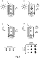
- FIG. 3 illustrated in four sub-figures, the control of both sides viewable embodiment FIG. 2A in which the disk 11 is transmissibly switchable and the display 10 is self-luminous.
- Full transmissivity, semi-transmissivity or impermeability are symbolized by horizontal, oblique or double hatching.
- the size of the circles in the display 10 represents the (basic) brightness setting and the contrast between the left and right half for the contrast setting.
- sub-figure 3A the case of a bright exterior / background, symbolized by a stylized sun, and a bright interior / environment, symbolized by a lamp icon, shown.
- the rear pane 11 is set to low transmissivity and the display 10 to high brightness and high contrast.
- Part 3B the case of a bright outdoor space / background, and a moderately light interior / environment is shown.
- the rear panel 11 is set to a medium transmissivity and the display 10 to normal brightness and normal to high contrast.
- Part 3C shows the case of a dark outer space / background, symbolized by a crescent moon, and a little light interior / environment.
- the method according to the invention provides for adjusting the rear pane 11 to a high transmissivity and the display 10 to low brightness and low to normal contrast.
- Partial 3D shows the case of a dark exterior / background and a bright interior / environment.
- the rear disk 11 is on a high transmissivity and the display 10 to adjust to normal high brightness and normal contrast. Since the same viewing direction B applies to all figures, the disk 11, seen from this direction, is always to be kept at 100% relative transmission.
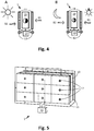
- the two subfigures A and B of FIG. 4 illustrate two possible cases in which, despite uneven lighting conditions on both sides of a simultaneous readability on both sides of an embodiment of the display device according to the invention after FIG. 2A is feasible, as symbolized by the two directional arrows for the main viewing directions B1 and B2.
- the discs 11 are here in transmissivity switchable.
- the display 11 is either self-luminous (oLED, LED, EL) or passive (TFT).
- Part A shows a daytime operation with a bright exterior and a moderately bright interior.
- both discs 11 are switched to very high transmissivity. Display brightness and contrast are to be selected high during daytime operation.
- Sub-part B illustrates the night mode.
- the main difference is that the general level of light is lower and therefore the display brightness can be set lower.
- a normal value is necessary because for the viewer on the bright inside (the side with the lamp pictogram) a certain minimum brightness is necessary.
- the disc 11 is set on this side to an average transmissivity.
- FIG. 5 shows another bilaterally viewable embodiment of the display device according to the present invention, in which the discs 11 are divided into sectors, each of which has its own, permanently assigned to the sector brightness sensor 12.
- the sensors transmit a sector-related and page-related measurement signal to the control unit 13, which then regulates the transparency and / or transmissivity of the panes according to the settings of the viewer or viewers.
- the principles according to which this is done correspond to those set out above.
- the advantage of this embodiment is that it is possible to regulate sector-dependent, as a result of which, for example, shadowing or punctual incidence of light can be compensated. In order to avoid unsightly sector borders, a rather high number of sufficiently small sectors is necessary. It is suitable for such a display device to use an LCD or TFT matrix as a switchable disc.
- the complexity in production and control can be reduced by the fact that larger pixels than usual for a screen display are used.
- FIG. 6 Exemplary of such a sector-dependent regulation are in FIG. 6 shown four cases in which transmissivity of the disc 11 and brightness and contrast of the display 10 for each sector is set individually according to the prevailing light conditions there.
- Sub-figures A and B illustrate the day sub-figures C and D night operation.
- Part A shows the case of shading in the case of viewing from a moderately bright environment in a bright outdoor space or looking at a bright background.
- sub-figure B the viewing direction is reversed, and a perturbation of the light spot on the less bright side must be compensated. This is done by reducing the transmissivity to an appropriate level only in the affected sector (s).
- Subfigure C shows how a backlighting spurious light source S2 relating to a sector can be masked out in the dark outer space by shading, ie inverse switching of the corresponding sector.
- the stray light source S1 shining out of the bright interior onto another sector of the front side in the viewing direction B1 is compensated for by increasing the brightness and possibly also the contrast setting of the corresponding sector of the display 10.
- sub-figure D the case of sub-figure C is shown in the reverse viewing direction.
- the sector irradiated by the disturbing light source S1 now remains completely transmissive, whereas the disc 11 lying behind the display 10 from the direction B2 is fundamentally switched to semi-transmissive with the exception of the sector which is irradiated by interfering light source S2.
- FIG. 7 shows a cross section through a pixel 20 of an LED display.
- LED 201 is mounted on circuit board 200 and emits light at least in two solid angle areas, here above and below. The downwardly emitted light may pass through the circuit board 200 through bore 2001.
- diverging lens 202 is mounted on the underside of the circuit board 200 concentric with the bore 2001.
Abstract
Anzeigevorrichtung, umfassend ein Displaypaneel (10) mit Vorder-und Rückseite, wobei eine angezeigte Information, insbesondere ein Text, Zeichen oder ein Bild, zumindest von der Vorderseite her betrachtbar ist, mindestens eine Scheibe (11) mit schaltbarer, insbesondere elektrisch schaltbarer Transparenz und/oder Transmissivität, wobei die Scheibe auf einer Seite des Displaypaneels (10) angeordnet ist, mindestens einen Lichtsensor (12) zum Messen einer Lichtintensität, und eine Regeleinheit (13), welche die Transparenz und/oder die Transmissivität der Scheibe (11) und Einstellungen des Displaypaneels (10) regelt, wobei die Regeleinheit (13) die Transparenz und/oder Transmissivität der Scheibe (11) und eine Helligkeit und/oder Kontrasteinstellung des Displaypaneels (10) so regelt, dass eine mittlere Bildhelligkeit als Summe eines vom Displaypaneel (10) erzeugten Lichtanteils und eines durch die Scheibe (12) transmittierten Lichtanteils, und ein Kontrastwert zwischen der angezeigten Information und einem Hintergrund im Wesentlichen einem voreingestellten oder von einem Betrachter wählbaren Wert entspricht.Display device, comprising a display panel (10) with front and back, wherein a displayed information, in particular a text, characters or an image, at least from the front is her viewable, at least one disc (11) with switchable, in particular electrically switchable transparency and / Transmissivity, wherein the disc is arranged on one side of the display panel (10), at least one light sensor (12) for measuring a light intensity, and a control unit (13), the transparency and / or the transmissivity of the disc (11) and Settings of the display panel (10) controls, wherein the control unit (13) the transparency and / or transmissivity of the disc (11) and a brightness and / or contrast adjustment of the display panel (10) so regulated that a mean image brightness as the sum of the display panel ( 10) and a proportion of light transmitted through the disc (12), and a contrast value between the displayed one Information and a background substantially corresponds to a preset or by a viewer selectable value.
Description
Die Erfindung betrifft eine Anzeigevorrichtung für Schriften und Bilder nach dem Oberbegriff des Anspruchs 1 sowie ein Verfahren zum Betreiben einer solchen Anzeigevorrichtung.The invention relates to a display device for fonts and images according to the preamble of
In den letzten Jahren wurden Bildschirme bzw. Displays entwickelt, die zumindest teilweise transparent sind, d. h. von der Rückseite auf das Display fallende Licht dieses zumindest teilweise passieren kann, so dass ein Benutzer bzw. Betrachter des Displays nicht nur die auf dem Display angezeigte Information, insbesondere Texte, Zeichen oder Bilder, sondern auch den hinter den Display gelegenen Hintergrund sieht.In recent years, screens have been developed which are at least partially transparent, that is, transparent. H. From the back of the display falling light this can happen at least partially, so that a user or viewer of the display sees not only displayed on the display information, especially text, characters or images, but also the background behind the display.
Dies ist aus verschiedenen Gründen ein gewünschter bzw. vorteilhafter Effekt. Zum einen bedeutet dies, da Transmission in alle Richtungen erfolgt, dass das Display beidseitig ablesbar ist. Des Weiteren lassen sich durch die Überlagerung von Anzeigebilder über den technischen Hintergrund auch Effekte erreichen, die mit einem nicht transparenten Display unmöglich sind, jedenfalls nicht ohne Zuhilfenahme einer zusätzlichen (Video-)Kamera. Dies sind zum Beispiel die Überlagerung von Kontextinformationen zu im Hintergrund sichtbaren Personen, Gegenständen oder Objekten, was auch als "augmented reality" bekannt ist.
Auch eröffnet sich durch solche Displays die Möglichkeit, sie als Head-Up-Displays zu verwenden, bei denen für den Betrachter wichtige Informationen, bei denen es vorteilhaft ist, wenn sie immer im Blickfeldschnellsicht und verfügbar sind, eingeblendet werden. Head-Up-Displays sind ursprünglich aus Militärflugzeugen bekannt, halten jedoch in jüngster Zeit auch in zivilen Flugzeugen und Fahrzeugen Einzug. Eine Realisierung mittels (Semi-)transparentem Bildschirm/Display wäre jedoch wesentlich einfach, kostengünstiger und platzsparender als die bisher bekannten Head-Up-Displays.
Der letzte Vorteil transparente Displays, der hier erwähnt werden soll, ist der ästhetische Effekt den eine scheinbar frei schwebende Schrift bzw. Bildinformation beim Betrachter erzeugt.This is a desired or advantageous effect for various reasons. On the one hand, this means that since transmission takes place in all directions, the display can be read on both sides. Furthermore, the superimposition of display images on the technical background can also achieve effects that are impossible with a non-transparent display, at least not without the help of an additional (video) camera. These are, for example, the superimposition of context information on persons, objects or objects visible in the background, which is also known as "augmented reality".
Such displays also open up the possibility of using them as head-up displays in which important information for the observer, in which it is advantageous if they are always available in the field of view and available quickly, is displayed. Head-up displays are originally known from military aircraft, but have recently found their way into civilian aircraft and vehicles. A realization by means of (semi) transparent screen / display However, would be much easier, cheaper and more space-saving than the previously known head-up displays.
The last advantage of transparent displays, which should be mentioned here, is the aesthetic effect that creates a seemingly free-floating font or image information in the viewer.
Ein wesentliches Problem solcher transparenter Displays stellt jedoch die Ablesbarkeit vor dem jeweiligen Hintergrund dar. Soll diese in jedem Fall gewährleistet sein, so muss zusätzlich zu dem eigentlichen Display, noch Vorkehrungen getroffen werden, entweder bei Bedarf den Hintergrund auszublenden, oder die Helligkeit bzw. den Kontrast des Displays soweit zu erhöhen, dass die anzuzeigende Information weiterhin erkennbar ist.An essential problem of such transparent displays, however, is the readability against the respective background. Should this be guaranteed in any case, then in addition to the actual display, still precautions must be taken, either hide the background if necessary, or the brightness or the Contrast of the display to increase so far that the information to be displayed is still recognizable.
Bisher bekannte Techniken von transparenten Displays umfassen zunächst TFT-Displays, die jedoch nur eine Transmission von ca. 10 % erreichen. Dies bedeutet, dass 90% des rückseitig beaufschlagten Lichts nicht den Betrachter erreicht. Des weiteren werden zur Zeit hochauflösende, selbstleuchtende oLED-Displays entwickelt, die Transmissionsgrade von 40-50 % erreichen. Die höchsten Transmissionsgrade, die bisher möglich sind, ergeben sich jedoch mit TEL (Transparentes ELectroluminiszenz) Displays, die Transmissionsgrade von bis zu 80 % aufweisen.Previously known techniques of transparent displays initially include TFT displays, which, however, only achieve a transmission of about 10%. This means that 90% of the light applied to the back does not reach the viewer. Furthermore, high-resolution, self-illuminating oLED displays are currently being developed which achieve transmittances of 40-50%. However, the highest transmittances that have been possible to date are achieved with TEL (Transparent Electroluminescent) displays, which have transmittances of up to 80%.
Im Stand der Technik sind zur Lösung des angesprochenen Problems verschiedene Vorschläge bekannt. So offenbart die europäische Patentanmeldungsschrift
Des Weiteren beschreibt die Patentanmeldung
Die Nachteile der vorgenannten Lösung bestehen darin, dass die Ablesbarkeit, d.h. im Wesentlichen Kontrast und Helligkeit, des Displays als Ganzes vom Benutzer bzw. Betrachter eingestellt werden müssen, und sie sich nicht automatisch den Lichtverhältnissen vor bzw. hinter dem Display anpassen.The disadvantages of the above solution are that the readability, i. essentially contrast and brightness of the display as a whole must be set by the user or viewer, and they do not automatically adjust to the lighting conditions in front of or behind the display.
Aufgabe vorliegender Erfindung ist es darum, eine Anzeigevorrichtung und ein Verfahren zum Betreiben derselben zu finden, die eine automatische, zügige und genaue Anpassung an der Ablesbarkeit an wechselnde Lichtverhältnisse sowohl auf der Betrachterseite als auch im Hintergrund gewährleisten.Object of the present invention is therefore to find a display device and a method for operating the same, which ensure automatic, rapid and accurate adjustment to the readability to changing lighting conditions both on the viewer side and in the background.
Als Lösung schlägt vorliegende Erfindung eine Anzeigevorrichtung nach dem Anspruch 1 vor, die nach dem im Anspruch 14 beschriebenen Verfahren betrieben wird.As a solution, the present invention proposes a display device according to
Wesentliches Element der Anzeigevorrichtung sind hierbei die in ihrer Transparenz regelbare Scheibe, die Lichtsensoren sowie die Regeleinheit, welche anhand der gemessenen Lichtintensitätswerte sowie vom Betrachter eingestellter, gewünschter Helligkeits- und Kontrastwerte Transparenz der Scheibe sowie Helligkeit und Kontrast des Displays so regelt, dass eine Ablesbarkeit der angezeigten Informationen gewährleistet ist.
Der eingestellte Transparenzwert ist hierbei zum einen abhängig von der gemessenen Helligkeit hinter der Scheibe, hier Hintergrundhelligkeit genannt, als auch von der auf der Betrachterseite herrschenden Helligkeit, hier als Umgebungshelligkeit bezeichnet. Weiterhin sind vom Betrachter eingestellte Helligkeits- und Kontrastwerte maßgeblich. Allgemein gilt, dass die Transparenz mit der Hintergrundhelligkeit und dem gewünschten Kontrast sinken, aber mit der Umgebungshelligkeit und der gewünschten (Bild-)Helligkeit steigen sollte.An essential element of the display device here are the controllable in its transparency disc, the light sensors and the control unit, which on the basis of the measured light intensity values and set by the viewer, desired brightness and contrast transparency transparency of the disc and brightness and contrast of the display so controls that a readability of the displayed information is guaranteed.
The set transparency value is dependent on the measured brightness behind the screen, here called background brightness, as well as on the brightness prevailing on the viewer side, here referred to as ambient brightness. Furthermore, the brightness and contrast values set by the viewer are decisive. In general, the transparency should decrease with the background brightness and the desired contrast, but should increase with the ambient brightness and the desired (image) brightness.
Als einfachste Realisierung schlägt vorliegende Erfindung eine proportionale, d.h. lineare Abhängigkeit vor. Andere mathematische Beziehungen sind jedoch ebenfalls denkbar, so zum Beispiel eine quadratische oder logarithmische Abhängigkeit. Letztere hat den Vorteil sich an die natürliche Adaption des menschlichen Auges angepasst zu sein. Für das subjektive Helligkeitsempfinden ist nämlich über mehrere Größenordnungen der Umgebungshelligkeit hinweg eine Veränderung der objektiven, Lichtintensität um einen gewissen Faktor nur mit einer, schrittweisen Veränderung der subjektiven Helligkeit verbunden. Diesem würde durch eine logarithmische Abhängigkeit der Transparenz Rechnung getragen.As the simplest realization, the present invention proposes a proportional, ie linear dependence. However, other mathematical relationships are also conceivable, such as a quadratic or logarithmic dependence. The latter has the advantage of being adapted to the natural adaptation of the human eye. For the subjective perception of brightness, a change in the objective, light intensity by a certain factor is associated with a gradual change in the subjective brightness over several orders of magnitude of the ambient brightness. This would be taken into account by a logarithmic dependence of transparency.
Als Referenzverwendung der Anzeigevorrichtung gemäß vorliegender Erfindung ist die Anbringung an eine Scheibe eines Raumes und/oder eines Fahrzeuges angedacht, so dass klar zwischen Lichtverhältnissen vor und hinter der Scheibe d.h. im Innen- und Außenraum unterschieden werden kann. Anhand einer Unterteilung in drei grobe Stufen sollen hier die möglichen Lichtverhältnissekombinationen und die von der Regeleinheit daraufhin nach dem erfindungsgemäßen Verfahren vorzunehmenden Transparenz- bzw. Kontrasteinstellungen beschrieben werden.As a reference use of the display device according to the present invention, the attachment to a pane of a room and / or a vehicle is contemplated, so that clearly between light conditions in front of and behind the pane, i. can be distinguished in the interior and exterior. On the basis of a subdivision into three rough stages, the possible combinations of light conditions and the transparency or contrast settings to be carried out by the control unit thereupon according to the method according to the invention are described here.
Es muss hierbei zunächst unterschieden werden, ob eine Sichtbarkeit des Hintergrundes gewünscht ist oder nicht. Im letzteren Falle würde die Scheibe einfach immer auf Intransparent/reflektierend geschaltet, mit möglicherweise der Ausnahme des Falles, das die Außenhelligkeit sehr gering ist. Kontrast und Helligkeit könnten dann alleine nach der Innenraum-/ Umgebungshelligkeit und den Benutzereinstellungen vorgenommen werden. Eine Ausnahme hierzu ist der Fall, dass die Scheibe nicht nur in ihrer Transparenz sondern auch in Ihrer Transmissivität schalt/steuerbar ist. 0% (relative) Transparenz und 100% (relative) Transmissivität bedeuten hierbei, dass zwar vollständige aber auch komplett diffuse Lichttransmission stattfindet, sodass nur eine gleich-mäßige Helligkeit, aber keinerlei klares Bild mehr zu erkennen ist. Zwischenstufen bei Variation dieser beiden als grundsätzlich unabhängig angesehener Parameter ergeben sich durch Interpolation.
Relative Transparenz bzw. Transmissivität meint hier die Transparenz bzw. Transmissivität relativ zu den vom jeweiligen Scheibenmaterial maximal möglichen Werten. Am Beispiel der Transmissivität T heißt dies, dass sich die relative Transmissivität Trel aus der absoluten Tabs nach der Formel 
![]()
![]()
Relative transparency or transmissivity here means the transparency or transmissivity relative to the maximum possible values of the respective disc material. Using the example of transmissivity T, this means that the relative transmissivity T rel is derived from the absolute T abs according to the formula ![]()
![]()
Als Beispiel und Illustration hierzu sollen zwei aus dem Stand der Technik bekannte, elektrisch schaltbare Scheibenmaterialen dienen. Zum einen sind sogenannte pdLC (polymer dispersed liquid crystal) Scheiben bekannt, die durch Anlegen einer Spannung in Ihrer absoluten Transparenz von nahezu 0% auf etwa 85% schaltbar sind. Zum Erreichen der maximalen Transparenz ist eine Spannung von etwa 60-120VAC nötig und der Schaltvorgang dauert ca. 100 ms.
Anders verhält es sich bei den sogenannten SPD (suspended particle device) Scheiben. Hierbei werden suspergierte Partikel durch eine angelegte Spannung parallel zueinander ausgerichtet und so die Transmissions- und Transparenzeigenschaften verändert. Ohne angelegte Spannung sind die Partikel zufällig verteilt und absorbieren dadurch auftreffendes Licht. Ab einer Spannung von ca. 60VAC sind alle Partikel ausgerichtet und die relative Transmission erreicht 100%, jedoch mit einem niedrigen Transparenzwert. Bei Spannungswerten dazwischen lassen sich relative Transmissionswerte zwischen 0 und 100% erreichen.By way of example and illustration, two electrically switchable disc materials known from the prior art are to be used. On the one hand, so-called pdLC (polymer dispersed liquid crystal) disks are known, which can be switched from almost 0% to about 85% by applying a voltage in their absolute transparency. To achieve the maximum transparency, a voltage of about 60-120VAC is required and the switching process takes about 100 ms.
The situation is different with the so-called SPD (suspended particle device) disks. In this case, dispersed particles are aligned parallel to each other by an applied voltage and thus the transmission and transparency properties are changed. Without applied voltage, the particles are randomly distributed and thereby absorb incident light. From a voltage of approx. 60VAC, all particles are aligned and the relative transmission reaches 100%, but with a low transparency value. With voltage values in between, relative transmission values between 0 and 100% can be achieved.
Ideal wären Scheibenmaterialien, bei denen sowohl Transparenz als auch Transmission unabhängig mittels steuerbar sind. Ersatzweise schlägt vorliegende Erfindung vor, dies durch Kombination zweier Scheiben unterschiedlichen Typs, etwa einer pdLC und SPD Scheibe zu erreichen. Denkbar ist auch die Integration von Schichten beider Materialien in eine Scheibe, d.h. beispielsweise eine pdLC-Schicht zwischen einer ersten und einer zweiten Elektrode und eine SPD Schicht zwischen der zweiten und einer dritten Elektrode. Mittels der beiden Spannungen zwischen der ersten und zweiten sowie der zweiten und dritten Elektrode wären dann Transmission und Transmission in gewissen Grenzen unabhängig voneinander kontrollierbar.Ideal would be disc materials in which both transparency and transmission are controlled independently by means. Alternatively, the present invention proposes to achieve this by combining two disks of different types, such as a pdLC and SPD disk. Also conceivable is the integration of layers of both materials in a disk, ie, for example, a pdLC layer between a first and a second electrode and an SPD layer between the second and a third electrode. By means of the two voltages between the first and second and the second and third electrodes, transmission and transmission would then be independently controllable within certain limits.
Blickt der Betrachter von einem hellen Innen- in einen hellen Außenraum so wird die hinter dem Display angebrachten Scheibe von der Regeleinheit auf kaum Transparenz geschaltet, sowie eine hohe Helligkeit und ein hoher Kontrast des Displays gewählt, welche mit dem vom Betrachter gewünschten Helligkeits- und Kontrasteinstellung skalieren. Das bedeutet, die Regeleinheit geht davon aus, dass grundsätzlich hoher bzw. höchster Kontrast und Helligkeit zur klaren Ablesbarkeit nötig sind, dies kann aber durch den Betrachter durch seine Einstellungen übergangen werden.If the viewer looks from a bright interior to a bright outdoor space, the control unit will switch the pane behind the display to barely transparent, as well as choose a high brightness and a high contrast of the display, which will match the brightness and contrast settings desired by the viewer scale. This means that the control unit assumes that basically high or highest contrast and brightness are required for clear readability, but this can be ignored by the viewer through his settings.
Wir beschreiben nun die Regelung einer erfindungsgemäßen Anzeigevorrichtung in neun verschiedenen Situationen, wobei angenommen wird, dass eine Sichtbarkeit des Hintergrundes gewünscht ist, da dies, wie oben dargelegt, der wesentlichere und interessantere Fall ist.We now describe the control of a display device according to the invention in nine different situations, assuming that background visibility is desired since, as stated above, this is the more essential and interesting case.
Geht der Blick des Betrachters von einem hellen Innen- in einen mäßig hellen Außenraum, so wird die Scheibe auf semi-transparent geschaltet, und Helligkeit und Kontrast des Displays sind ebenfalls bezüglich des vom Betrachter gewählten Wertes hoch einzustellen. Ist der Außenraum bzw. der Hintergrund nur mäßig hell, so ist eine semi-transparente bis weitgehend transparente Einstellung zu wählen. Grundhelligkeit des Displays sollte weiterhin hoch sein, der Kontrast kann hoch bis normal gewählt werden, da die Auswaschung durch die Hintergrundhelligkeit geringer ist als im ersten Fall.If the viewer's gaze goes from a bright interior to a moderately bright outside space, the window is switched to semi-transparent, and the brightness and contrast of the display are also set high with regard to the value selected by the viewer. If the outside space or the background is only moderately light, a semi-transparent to largely transparent setting must be selected. The basic brightness of the display should still be high, the contrast can be selected to be high to normal, since the leaching by the background brightness is lower than in the first case.
Ist die Lichtintensität auf der Betrachterseite hoch, hinter dem Display jedoch niedrig, so kann die Scheibe auf vollständige Transparenz geschaltet werden, die Helligkeit ist weiterhin hoch, jedoch ist eine hohe Kontrasteinstellung nicht unbedingt notwendig, da von der Rückseite des Displays kaum eine zusätzliche, den Kontrast reduzierende Hinterleuchtung stattfindet.
Geht der Blick des Betrachters durch das Display von einem mäßig hellen Innen- in einen hellen Außenraum, so ist die Scheibe auf semitransparent zu schalten, und eine mittlere Helligkeit, jedoch ein hoher Kontrast zu wählen.
Geht der Blick von einem mäßig hellen Innen- in einen mäßig hellen Außenraum an die Scheibe ebenfalls semitransparent sein, Kontrast und Helligkeit sind dann beide relativ zu dem vom Betrachter gewählten gewünschten Wert mittelhoch einzustellen.
Ist der Innenraum von mäßiger Helligkeit erfüllt, der Außenraum hinter der Anzeigevorrichtung jedoch dunkel, kann die Scheibe vollständig transparent eingestellt werden, die Helligkeitseinstellung des Displays ist mittelgroß/normal zu wählen und der Kontrast ebenfalls.
Ist der Innenraum dunkel, der Außenraum jedoch hell so ist die Scheibe auf nahezu intransparent einzustellen, und die Helligkeit des Displays eher niedrig zu wählen, der Kontrast sollte jedoch normal oder niedrig sein.
Ist die Außenhelligkeit jedoch nur mäßig so kann eine semitransparente Einstellung der Scheibe gewählt werden, Helligkeit und Kontrast würden von der Regeleinheit jedoch wie im vorhergehenden Fall eingestellt.
Als letzter Fall wird ein dunkler Innenraum und ein dunkler Außenraum betrachtet. Hierbei ist bzw. kann die Scheibe vollständig transparent sein, um sicherzustellen, dass keine Lichtquellen übersehen werden. Helligkeit und Kontrast sind eher niedrig zu wählen.If the light intensity on the viewer side is high, but behind the display is low, the lens can be switched to full transparency, the brightness is still high, but a high contrast setting is not absolutely necessary, because of the back of the display hardly an additional Contrast-reducing backlighting takes place.
If the viewer's gaze goes from a moderately bright interior to a bright exterior through the display, then the pane should be switched to semi-transparent, and medium brightness but high contrast selected.
If the view from a moderately bright interior to a moderately bright exterior is also semitransparent to the pane, contrast and brightness are then set to be medium high relative to the desired value chosen by the viewer.
However, if the interior is moderately bright but the outside space behind the display is dark, the screen can be set to be completely transparent, the brightness setting of the display is medium / normal and the contrast is also good.
If the interior is dark, but the exterior is bright, the lens should be set to almost non-transparent, and the screen's brightness should be low, but the contrast should be normal or low.
However, if the external brightness is only moderate, a semitransparent adjustment of the pane can be selected, but brightness and contrast would be adjusted by the control unit as in the previous case.
The last case considered is a dark interior and a dark exterior. In this case, the pane can be completely transparent to ensure that no light sources are overlooked. Brightness and contrast are rather low.
Vorstehendes Regelverhalten der Regeleinheit der erfindungsgemäßen Anzeigevorrichtung gilt für den Fall, dass eine im Wesentlichen klare Sicht auf den Hintergrund gewünscht ist, so dass die angezeigte Information zusammen mit dem im Hintergrund befindlichen Objekten sichtbar ist. Dafür wird eine in ihrer Transparenz schaltbare Scheibe benötigt. Soll das von der Rückseite beaufschlagte Licht nur zur zusätzlichen Rückbeleuchtung verwendet werden, ist jedoch eine diffuse, in ihrer Transmission schaltbare Scheibe nötig. Oben beschriebenes Regelverhalten könnte jedoch weitgehend unverändert bleiben.The above control behavior of the control unit of the display device according to the invention applies to the case that a substantially clear view of the background is desired, so that the displayed information is visible together with the objects located in the background. For a switchable in its transparency disc is needed. If the light applied from the rear side is to be used only for additional backlighting, however, a diffuse disk which can be switched in its transmission is necessary. However, the above-described control behavior could remain largely unchanged.
Die Vorteile der erfindungsgemäßen Anzeigevorrichtung sind zum einen die automatische und schnelle Anpassung der Ablesbarkeit an die Lichtverhältnisse und die Wünsche des Betrachters. Hierbei ist wesentlich, dass diese wesentlich schneller zu reagieren vermag als eine manuelle Nachregelung durch einen Betrachter und offensichtlich auch deutlich komfortabler ist. Darüber hinaus ist je nach Bedarf die IR Einstrahlung reduzierbar, wodurch eine übermäßige Aufheizung des Innenraums vermieden werden kann.The advantages of the display device according to the invention are on the one hand the automatic and rapid adaptation of the readability to the lighting conditions and the wishes of the beholder. It is essential that this is able to react much faster than a manual readjustment by a viewer and obviously also much more comfortable. In addition, as required, the IR radiation can be reduced, whereby excessive heating of the interior can be avoided.
Durch die Ausstattung der Anzeigevorrichtung mit einer in ihrer Transparenz und/oder Transmission schaltbaren Scheibe, welche auch eine Fensterscheibe sein kann, ergibt sich eine vielseitige Verwendbarkeit der erfindungsgemäßen Anzeigevorrichtung. Zum einen ist es möglich, bei vollständiger Transparenzschaltung und ausgeschaltetem Display sie als einfaches Fenster zu verwenden. Des Weiteren, ebenfalls bei ausgeschaltetem Display bzw. wenn keine Information darauf angezeigt wird, stellt die erfindungsgemäße Anzeigevorrichtung ein in seiner Durchlässigkeit schaltbares Fenster dar, so dass etwa bei starker Sonneneinstrahlung die Aufheizung eines Raumes oder Fahrzeugs reduziert werden kann, indem die relative Transparenz auf einen Wert unter 100% reduziert wird. Dies kommt zum einen dem Komfort der im Raum bzw. Fahrzeug befindlichen Personen zugute, hat Zugleich aber auch den wichtigen technischen Vorteil die thermische Belastung von Geräten, inklusive der erfindungsgemäßen Anzeigevorrichtung selbst, zu verringern, was deren Lebensdauer und MTBF (mean time between failure) vorteilhaft erhöht. Ist eine vollständige Intransparenz bzw. Undurchlässigkeit der Scheibe möglich, so ist der lichtdichte Abschluss eines Raumes, zum Beispiel als Ersatz für Roll- bzw. Fensterläden möglich. Die diffus transmittierende Scheiben bei denen der Transmissionsgrad schaltbar ist, erlauben einen blickdichten Verschluss, der Privatsphäre gewährleistet und bei dem der Lichteinfall regelbar ist.By equipping the display device with a switchable in its transparency and / or transmission disc, which may also be a window, results in a versatility of the display device according to the invention. On the one hand, it is possible to use it as a simple window with complete transparency switching and the display switched off. Furthermore, likewise when the display is switched off or when no information is displayed thereon, the display device according to the invention represents a window which can be switched in its permeability, so that the heating of a room or vehicle can be reduced, for example in the case of strong solar radiation, by the Relative transparency is reduced to a value below 100%. On the one hand, this benefits the comfort of the persons or people in the room, but at the same time it also has the important technical advantage of reducing the thermal load on devices, including the display device according to the invention, thereby reducing their service life and MTBF (mean time between failure). advantageously increased. If a complete lack of transparency or impermeability of the pane is possible, then the light-tight closure of a room, for example, as a replacement for shutters or shutters is possible. The diffusely transmissive discs with which the transmittance is switchable, allow an opaque closure that ensures privacy and in which the light is adjustable.
Weitergehende Ausführungsformen, welche einzeln oder in Kombination realisierbar sind, sofern sie sich nicht offensichtlich gegenseitig ausschließen, sollen im Folgenden erläutert werden.Further embodiments, which can be implemented individually or in combination, unless they are obviously mutually exclusive, will be explained below.
Idealerweise wäre die in der erfindungsgemäßen Anzeigevorrichtung verwendete Scheibe sowohl in ihrer absoluten Transmission als auch in ihrer absoluten Transparenz jeweils von etwa 0-100 % steuerbar. Dem Stand der Technik ist jedoch keine Realisierung einer solchen Scheibe bekannt. Bei den oben erwähnten SPD-Scheiben ist hauptsächlich die Transmission schaltbar, jedoch ändert sich die Transparenz dabei ebenfalls und zwar so, dass sowohl bei relativer Transmissivität von 0 und 100% eine diffuse Transmission stattfindet, die Scheibe also undurchsichtig ist, bei Transmissionswerten dazwischen jedoch eine gewisse Transparenz gegeben ist, die Scheibe also zumindest zu einem gewissen Grad durchsichtig ist.
Die weiterhin bekannten pdLC-Scheiben können von undurchsichtig durch Anlegen einer Spannung auf durchsichtig geschaltet werden.Ideally, the disk used in the display device according to the invention would be controllable both in its absolute transmission and in its absolute transparency in each case from about 0-100%. The prior art, however, no realization of such a disc is known. In the case of the above-mentioned SPD disks, the transmission is mainly switchable, but the transparency also changes in such a way that a diffuse transmission takes place both at relative transmissivity of 0 and 100%, ie the disk is opaque, but with transmission values therebetween certain transparency is given, the disc is so transparent, at least to a degree.
The still known pdLC disks can be switched from opaque to transparent by applying a voltage.
Da sie im undurchsichtigen Zustand auftreffendes Licht nicht einfach absorbieren (wie z.B. SPD Scheiben), sondern zum Großteil, wenn auch diffusiv, zurückwerfen, eignen sie sich als elektrisch steuerbarer Transflektor für die Hinterleuchtung von TFT-Displays. Die Kombination beider Scheibentypen, d.h. Anbringen einer über dem anderen ergäbe sich ein Element welches sowohl Transmissivität als auch in Transparenz steuerbar ist, jedoch zu dem Preis einer erhöhten Komplexität, höheren Kosten und einen niedrigeren absoluten Transmission und Transparenz.Since they do not simply absorb incident light in the opaque state (such as SPD disks), but throw it back largely, albeit diffusely, they are suitable as an electrically controllable transflector for the backlighting of TFT displays. The combination of both types of discs, i. Attaching one over the other would result in an element that is both transmissive and controllable in transparency but at the cost of increased complexity, higher cost and lower absolute transmission and transparency.
In einer bevorzugten Ausführungsform werden zwei gleichartige Scheiben (z.B. zwei SPD oder zwei pdLC Scheiben) auf verschiedenen Seiten des Displays angeordnet und, in der Regel parallel zu diesem und entweder beabstandet oder direkt an dieses anliegend befestigt ist, empfiehlt vorliegende Erfindung, ein beidseitig ables- bzw. betrachtbares Displaypaneel zu verwenden. Hierfür kommen zum einen TFT-Displays in Frage. Üblicherweise bestehen diese aus einer Vielzahl rasterartig angeordneter Bildpunkte, deren jeder, bei einem Farbdisplay, aus je einer roten, blauen und grünen Flüssigkristallzelle (LCD) aufgebaut ist. Jede LCD Zelle wird hierbei von einem Dünnschichttransistoren angesteuert und auf mehr oder weniger lichtdurchlässig geschaltet. Durch die dünne Ausführung der Transistoren ist eine Transparenz gewährleistet, wobei maximal möglichen absoluten Transmissionsgrade allerdings nur ca. 50 % betragen. Ein TFT-Display hat keine bevorzugte Betrachtungsrichtung, daher ist sie natürlicherweise von beiden Seiten ablesbar, wenn eine entsprechende Hinterleuchtung gegeben ist.
Der Vorteil von TFT Displays besteht darin, dass sie eine sehr gut beherrschte, ausgereifte Technologie darstellen und sehr hohe Informationsdichten von derzeit bis zu ca. 400ppi (pixel per inch, Pixel pro Zoll) ermöglichen. Für jedes Pixel ist es einzeln möglich, die relative Transparenz von 0 bis 100% zu ändern. Somit würde sich ein TFT Matrix auch als schaltbare Scheibe eignen, wäre jedoch wesentlich komplexer in der Herstellung und Ansteuerung.In a preferred embodiment, two similar slices (eg two SPD or two pdLC slices) are placed on different sides of the display and, usually parallel to it and either spaced or directly attached to it, the present invention recommends that a two-sided reading be made. or viewable display panel to use. For this purpose, on the one hand TFT displays in question. Usually, these consist of a plurality of grid-like arranged pixels, each of which, in a color display, each of a red, blue and green liquid crystal cell (LCD) is constructed. Each LCD cell is controlled by a thin-film transistor and switched to more or less translucent. The thin design of the transistors ensures transparency, although maximum possible absolute transmittances are only about 50%. A TFT display does not have a preferred viewing direction, so it is naturally readable from both sides if there is appropriate backlighting.
The advantage of TFT displays is that they represent a very well-controlled, mature technology and enable very high information densities of currently up to about 400ppi (pixels per inch, pixels per inch). For each pixel, it is individually possible, the relative To change transparency from 0 to 100%. Thus, a TFT matrix would also be suitable as a switchable disk, but would be much more complex in the production and control.
Sind sehr hohe absolute Transmissionsgrade gewünscht und eine hohe Informationsdichte zweitrangig, ist ein beidseitig ablesbares EL-Display denkbar (EL = ElektroLuminizenz), Es besteht aus einem Sandwich aus zwei leitenden Schichten, welche zwischen sich eine Schicht eines elektroluminiszenten Materials einschließen. Fließt ein Strom von der einen in die andere leitende Schicht, so leuchtet das dazwischenliegende elektroluminiszente Material unter auf. Sind beide leitende Schichten aus einem transparenten Material gefertigt, ergibt sich ein beidseitig ablesbares EL-Display, auch kurz als TEL, oder transparentes elektroluminiszentes Display, bezeichnet. Hierbei erreichbare Transmissionsgrade betragen bis zu 80 %.If very high absolute transmittances are desired and a high information density is of secondary importance, a double-sided readable EL display is conceivable (EL = electro-luminous license). It consists of a sandwich of two conductive layers which enclose between them a layer of an electroluminescent material. If a current flows from one to the other conductive layer, the intermediate electroluminescent material illuminates under. If both conductive layers are made of a transparent material, this results in a double-sided readable EL display, also referred to as TEL for short, or transparent electroluminescent display. Achievable transmittances are up to 80%.
Die farblich brillantesten Bilder mit einer Auflösung, die der von TFT-Displays entspricht, sind jedoch mit sogenannten transparenten oLED (organic LED)-Displays erreichbar. Sie bestehen aus rasterartig bzw. maxtrixartig angeordenten Bildpunkten, wobei jedem Bildpunkt jeweils mindestens eine Leuchtdiode je einer der drei Grundfarben rot, grün und blau zugeordnet ist. Diese Leuchtioden sind aus einem organischem Material, gefertigt, was dem Display seinen Namen gibt, und auf einem Substrat abgelegt, welches auch die elektrischen Zuleitungen zu jedem Bildpunkt enthält. Ist dieses Substrat transparent, erhält man ein zumindest teilweise transparentes Display. Transmissivität bzw. Transparenz eines solchen oLED-Displays wird durch das Substrat und die darin vorhandenen Ansteuerungsleitungen der oLEDs reduziert. Sie erreicht bei derzeitigen Modellen zwischen 40-50 % des beaufschlagten Lichtes. Der Vorteil von OLED-Displays ist, dass eine sehr gleichmäßige Ausleuchtung und hohe Brillanz erreicht werden kann, da hier der Bildpunkt selbstleuchtend ist und nicht über einen TFT-Display auf eine Hinterleuchtung angewiesen ist. Erreichbare Bildpunktgrößen liegen im Bereich von einigen 10 Mikrometern, und somit entspricht die Informationsdichte in etwa der eines TFT-Displays.However, the most brilliantly colored images with a resolution similar to that of TFT displays can be achieved with so-called transparent oLED (organic LED) displays. They consist of raster-like or maxtrixartig angeordenten pixels, each pixel is assigned at least one LED each one of the three primary colors red, green and blue. These light-emitting diodes are made of an organic material, which gives the display its name, and deposited on a substrate which also contains the electrical leads to each pixel. If this substrate is transparent, an at least partially transparent display is obtained. Transmissivity or transparency of such an oLED display is reduced by the substrate and the control lines of the oLEDs present therein. In current models, it reaches between 40-50% of the applied light. The advantage of OLED displays is that a very uniform illumination and high brilliance can be achieved because the pixel is self-luminous and does not rely on a TFT display backlighting. Achievable pixel sizes are in the range of a few 10 micrometers, and thus the information density is about the same as a TFT display.
Anstelle eines transparenten Substrats wäre auch denkbar, ein intransparentes Substrat mit einem unterhalb des LED eingebrachten Bohrung zu verwenden. Um den Betrachtungswinkel auf der rückwärtigen Seite dem auf der Vorderseite anzugleichen, wäre es vorteilhaft, Ausgangsseitig der Bohrung eine Zerstreuungslinse zu positionieren. Dieser prinzipielle Aufbau ist bei oLEDs und pLEDs, aber auch bei konventionellen, auf einer Leiterplatte montierten anorganischen LEDs anwendbar.Instead of a transparent substrate, it would also be conceivable to use an intransparent substrate with a bore introduced underneath the LED. In order to match the viewing angle on the rear side with that on the front side, it would be advantageous to position a diverging lens on the output side of the bore. This basic structure can be used with oLEDs and pLEDs, but also with conventional inorganic LEDs mounted on a printed circuit board.
Bei TFT und oLED sowie oft auch bei EL-Displays werden die Bildpunkte im Allgemeinen raster- oder matrixartig angeordnet, so dass, bei genügend hoher Auflösung, allgemeine Zeichen, Texte oder Bilder und zwar statisch oder bewegt angezeigt werden können. Für spezielle Anwendungen ist jedoch auch denkbar, dass die Bildpunkte nicht raster- oder matrixartig sondern anderweitig angeordnet sind. Zum Beispiel können schon vorgefertigte Schriftzüge und/oder Zeichen auf dem Display vorhanden sein, so dass sich die Anzeigefähigkeit des Displays auf einen begrenzten Satz an Formen oder Zeichen beschränkt. Dies ist z. B. bei sogenannten 7-Segementanzeigen von digitalen Uhren der Fall. Solche nichtrasterartige Displays lassen sich im Prinzip mit allen oben angesprochenen Anzeigetypen realisieren. Da dieses Prinzip jedoch nur für niedrige Informationsdichten praktikabel ist, eignen sich hierfür aber insbesondere EL- und LED Displays.With TFT and oLED and often also with EL displays, the pixels are generally arranged in a grid or matrix, so that, if the resolution is sufficiently high, general characters, texts or images can be displayed statically or in motion. For special applications, however, it is also conceivable that the pixels are not arranged in a grid or matrix manner but otherwise. For example, pre-written lettering and / or characters may be present on the display so that the display capability of the display is limited to a limited set of shapes or characters. This is z. As in so-called 7-segment displays of digital watches the case. Such non-grid-like displays can be realized in principle with all the above-mentioned display types. However, since this principle is only practicable for low information densities, in particular EL and LED displays are suitable for this purpose.
Vorliegende Erfindung schlägt weiterhin in einer bevorzugten Ausführungsform vor, dass die Scheibe getrennt schaltbare Sektoren aufweist. Diese Sektoren können matrixartig oder auch unregelmäßig über die Fläche der Scheibe verteilt sein, sollten jedoch die Scheibenfläche vollständig ausfüllen. Jeder Sektor benötigt zur Steuerung der Transparenz und/oder Transmissivität zumindest zwei elektrische Zuleitungen. Diese sollen gemäß vorliegender Erfindung bevorzugt zumindest für die nicht an den Rand der Scheibe angrenzenden Sektoren so ausgestaltet sein, dass der Querschnitt der Zuleitung parallel zu einer Hauptbetrachtungsrichtung eine wesentlich größere Ausdehnung als senkrecht aufweist.The present invention also proposes, in a preferred embodiment, that the disc has separately switchable sectors. These sectors may be distributed in a matrix-like or irregular manner over the surface of the disk, but should completely fill the disk surface. Each sector requires at least two electrical leads to control transparency and / or transmissivity. These should preferably be designed according to the present invention, at least for the not adjacent to the edge of the disc sectors so that the cross section of the lead parallel to a main viewing direction has a substantially greater extent than perpendicular.
Die Scheibe vorliegender Erfindung kann ein separates Element, oder eine eventuell schon vorhandene elektrisch schaltbare Fensterscheibe eines Raums und/oder Fahrzeugs sein. Im ersteren Fall erhält man eine mobile nutzbare Anzeigevorrichtung, in letzterem Fall hingegen spart man das zusätzliche Vorsehen einer in Transparenz und/oder Transmissivität schaltbaren Scheibe ein.The pane of the present invention may be a separate element, or any existing electrically switchable window pane of a room and / or vehicle. In the former case, one obtains a mobile usable display device, in the latter case, however, saves the additional provision of a switchable in transparency and / or transmissivity disc.
Der Sensor und die Regelreinheit der erfindungsgemäßen Anzeigevorrichtung können verschiedenartig ausgestaltet sein. Eine Möglichkeit ist, dass beide Funktionen von physisch getrennten Einrichtungen ausgeführt werden. Das heißt Sensoren sind am Rand oder auch an einem Punkt im Inneren der Fläche der Scheibe installiert und verfügen über Signalleitungen, über welche die Messwerte in digitaler oder auch analoger Form an die Regeleinheit weitergegeben werden, welche bevorzugt außerhalb der Scheibenfläche, z. B. an einer der Scheibenstirnseiten, oder an einer Stirnseite des Displays angeordnet ist.
Es ist aber auch möglich, und sinnvoll, besonders wenn nur ein Sensor vorhanden ist, dass dieser in die Regeleinheit integriert ist.The sensor and the control purity of the display device according to the invention can be configured in various ways. One possibility is that both functions are performed by physically separate devices. That is sensors are installed at the edge or at a point inside the surface of the disc and have signal lines through which the measurements are passed in digital or analog form to the control unit, which preferably outside the disc surface, for. B. on one of the disc end faces, or disposed on an end face of the display.
But it is also possible, and useful, especially if only one sensor is present, that this is integrated into the control unit.
Dadurch werden die Signallaufwege minimiert und die gesamte zur Steuerung notwendige Elektronik kann in einem Installationsschritt an Scheibe und Display angebracht werden. Bevorzugt wäre hierbei die Regeleinheit so ausgestaltet, dass auf zwei gegenüberliegenden Stirnseiten jeweils ein Lichtsensor angebracht ist, der ein aus dem jeweiligen Halbraum kommende Lichtintensität misst.As a result, the signal propagation paths are minimized and the entire electronics required for control can be attached to the pane and display in one installation step. In this case, the control unit would preferably be configured in such a way that a light sensor is mounted on each of two opposite end faces and measures a light intensity coming from the respective half-space.
Gemäß einer weiteren bevorzugten Ausführungsform der vorliegenden Erfindung ist mehr als ein Lichtsensor vorhanden. Insbesondere ist es vorteilhaft, wenn pro betrachtbarer Seite bzw. Hauptbetrachtungsrichtung des Displays und/oder pro schaltbarem Sektor der Scheibe mindestens ein Lichtsensor vorhanden ist. Dieser ist dem jeweiligen Sektor und/oder der Blickrichtung fest zugeordnet und leitet ein auf den Sektor bezogenes Messsignal an die zugehörige Regeleinheit weiter. Dies kann eine zentrale Regeleinheit zur Auswertung aller Lichtmesssignale der erfindungsgemäßen Anzeigevorrichtung sein, oder es handelt sich jeweils um eine ebenfalls einem Sektor und/oder Hauptbetrachtungsrichtung zugeordnete Regeleinheit. In letzterem Fall mehrere vorhandene Regeleinheiten hätte den Vorteil, dass auch eine sektorbezogene Regelung der Kontrast- und Helligkeitseinstellung des Displays leichter durchzuführen wäre, sofern den schaltbaren Sektor an der Scheibe auch getrennt ansteuerbare Sektoren des Displays zugeordnet sind.In accordance with another preferred embodiment of the present invention, more than one light sensor is present. In particular, it is advantageous if at least one light sensor is present per viewable side or main viewing direction of the display and / or per switchable sector of the pane. This is permanently assigned to the respective sector and / or the viewing direction and forwards a measurement signal related to the sector to the associated control unit. This can be a central control unit for evaluating all the light measuring signals of the display device according to the invention, or it is in each case also a control unit which is likewise assigned to a sector and / or main viewing direction. In the latter case, several existing control units would have the advantage that a sector-related control of the contrast and brightness adjustment of the display would be easier to perform, if the switchable sector on the disc are also assigned separately controllable sectors of the display.
In weiteren Ausführungsformen ist die Scheibe mit dem Displaypaneel fest verbunden. Bevorzugt geschieht dies im Optical Contact Bond Verfahren, d.h. klebstofflos und nur durch intermolekulare Kräfte zwischen den bis auf höchste Toleranzen komplementär geformten Kontaktoberflächen von Schiebe und Display. Hierdurch wird der erreichbare Kontrast weiter verbessert.In further embodiments, the disc is firmly connected to the display panel. This is preferably done in the optical contact bonding method, ie adhesive and only by intermolecular forces between the up to the highest tolerances complementarily shaped contact surfaces of sliding and display. As a result, the achievable contrast is further improved.
In weiteren Ausführungsformen verfügt die erfindungsgemäße Anzeigevorrichtung über Hinterleuchtungsquellen, die an einer oder mehreren Stirnseiten der Scheibe, beispielsweise an gegenüberliegenden Stirnseiten angebracht sind. Diese Hinterleuchtung ist besonders bevorzugt eine schmale LED Lichtquelle (sog. "edge light LED").In further embodiments, the display device according to the invention has backlight sources, which are attached to one or more end faces of the disc, for example on opposite end sides. This backlight is particularly preferably a narrow LED light source (so-called "edge light LED").
Die Hauptbetrachtungsrichtung(en) eines Displays sollen hier als die relativen Richtungen verstanden werden, aus denen ein Betrachter das klarste, hellste und kontrastreichste Bild sieht. Üblicherweise sind Displays so konstruiert, dass diese Richtung im Wesentlichen senkrecht zur Displayebene steht. Bei einem zweiseitig ablesbaren Display wären die Hauptbetrachtungsrichtungen üblicherweise beide möglichen Flächensenkrechten.The main viewing direction (s) of a display should be understood here as the relative directions from which a viewer sees the clearest, brightest and most contrasting image. Typically, displays are designed so that this direction is substantially perpendicular to the display plane. For a two-sidedly readable display, the main viewing directions would usually be both possible surface perpendiculars.
Bei dem erfindungsgemäßen Verfahren zum Betreiben einer hier vorgestellten Anzeigevorrichtung wird zunächst durch einen Betrachter einer Hauptbetrachtungsrichtung ausgewählt, d.h. der Betrachter wählt eine der maximal zwei möglichen betrachtbaren Seiten als die 'aktive' Seite aus. Dies kann entweder durch Betätigung eines entsprechenden Bedienelementes oder aber auch automatisiert durch Auswertung von Bildern einer zugeordneten Kamera und Weiterleitung der entsprechenden Informationen an die erfindungsgemäße Vorrichtung erfolgen. Weiterhin wählt der Betrachter eine Helligkeits- und Kontrasteinstellung, die bevorzugterweise für das gesamte Display gilt, d.h. heißt nicht für jeden Sektor einzeln eingestellt werden muss.
Gekennzeichnet ist das erfindungsgemäße Verfahren dadurch, dass zunächst der Lichtsensor eine lokale Helligkeit misst und an die Regeleinheit weiterleitet, Regeleinheit für jeden Sektor Transparenz und/oder Transmission so regelt, dass hier die Intensität unter einem zulässigen Maximalwert liegt und weiterhin die Regeleinheit Helligkeit und Kontrast des Displaypaneels so anpasst, dass sie aus der gewählten Betrachtungsrichtung gesehen, eine von der gemessenen Lichtintensität und den vom Betrachter gewählten Einstellungen abhängigen Wert entsprechen, und sodann die dazustellende Informationen auf dem Display angezeigt wird.In the method according to the invention for operating a display device presented here, a viewer first selects a main viewing direction, ie the viewer selects one of the maximum two possible viewable pages as the 'active' page. This can be done either by actuation of a corresponding operating element or else automatically by evaluating images of an associated camera and forwarding the corresponding information to the device according to the invention. Furthermore, the viewer selects a brightness and contrast setting which preferably applies to the entire display, ie does not have to be set individually for each sector.
The inventive method is characterized in that first the light sensor measures a local brightness and forwards it to the control unit, control unit for each sector transparency and / or transmission controls so that here the intensity below a permissible maximum value and furthermore adjusts the control unit brightness and contrast of the display panel so that they are seen from the selected viewing direction, one dependent on the measured light intensity and the settings selected by the viewer value, and then the information to be displayed on the display.
Es ist hierbei bevorzugt, dass diese drei Schritte in regemäßigen oder unregelmäßigen Abständen dem Beispiel innerhalb der Ansprechzeit der Scheibe und/oder des Displays wiederholt werden. Dies sollte insbesondere dann geschehen, wenn der Benutzer die gewünschten Kontrast- und Helligkeitseinstellungen ändert.It is hereby preferred that these three steps are repeated at regular or irregular intervals from the example within the response time of the disc and / or the display. This should especially happen when the user changes the desired contrast and brightness settings.
Der für die Regelung der Transmissivität bzw. der Transparenz der Scheibe der erfindungsgemäßen Anzeigevorrichtung herangezogene Maximalwert ergibt sich aus den vom Benutzer gewünschten Helligkeits- und Kontrasteinstellungen, welche über entsprechende Eingabemittel der Regeleinheit mitgeteilt werden können. Es ist bevorzugt, dass dieser Maximalwert proportional zur vom Benutzer gewählten Helligkeitseinstellung steigt, sowie proportional zur vom Benutzer gewählten Kontrasteinstellung sinkt. Dadurch wird sichergestellt, dass durch die von der Scheibe durchgelassene Hintergrundhelligkeit das darzustellende Bild nicht überstrahlt bzw. der Kontrast und der das vom Benutzer gewünschte Niveau vermindert wird.The maximum value used for regulating the transmissivity or the transparency of the pane of the display device according to the invention results from the brightness and contrast settings desired by the user, which can be communicated to the control unit via corresponding input means. It is preferred that this maximum value increase in proportion to the user-selected brightness setting as well as decrease in proportion to the user-selected contrast setting. This ensures that the background brightness transmitted through the pane does not overshadow the image to be displayed, or that the contrast and the level desired by the user are reduced.
Weiterhin wird und von der Erfindung bevorzugt, dass bei dem erfindungsgemäßen Verfahren die Lichtsensoren auf der gewählten Betrachtungsrichtung vorderen Seite eine sektorabhängige Umgebungshelligkeit und die in Betrachtungsrichtung rückseitig liegenden Lichtsensoren eine sektorabhängige Hintergrundhelligkeit messen und zur Regelung der Transparenz zumindest die sektorabhängige Hinterleuchtung und zur Regelung der Helligkeit- und/oder Kontrasteinstellung zumindest die Umgebungshelligkeit herangezogen wird.Furthermore, it is preferred by the invention that in the method according to the invention the light sensors measure a sector-dependent ambient brightness on the selected viewing direction front side and the light sensors located on the rear side in the viewing direction measure a sector-dependent background brightness and at least the sector-dependent one for controlling the transparency Backlighting and to control the brightness and / or contrast setting at least the ambient brightness is used.
Vorliegende Erfindung schlägt vor, die Scheibentransparenz mit zunehmender Hintergrundhelligkeit zu senken, wobei in einer möglichen Ausführungsform die Transparenz umgekehrt proportional zur gemessenen Hintergrundhelligkeit ist.
Weiter wird vorgeschlagen, die Helligkeits- und Kontrasteinstellungen mit steigender Umgebungshelligkeit zu erhöhen, beispielsweise mit linearer Abhängigkeit.The present invention proposes to reduce the transparency of the disc with increasing background brightness, wherein in one possible embodiment the transparency is inversely proportional to the measured background brightness.
It is also proposed to increase the brightness and contrast settings with increasing ambient brightness, for example with linear dependency.
Des Weiteren wird bevorzugt, dass auch die Regelung und Kontrast- und/oder Helligkeitseinstellung des Displays sektorabhängig erfolgt. Ist die Scheibe der erfindungsgemäßen Anzeigevorrichtung sowohl in Transparenz als auch Transmissivität schaltbar, so schlägt vorliegende Erfindung vor, falls eine Sichtbarkeit des Hintergrundes nicht erwünscht oder nötig ist, das von der aus der Betrachtungsrichtung rückwärtigen Seite aus auf die Anzeigevorrichtung auftreffende Licht zur Displayhinterleuchtung zu verwenden.
Hier ist zwischen verschiedenen Displaytypen zu unterscheiden. Ein LCD- bzw. TFT-Display ist in jedem Fall auf Hinterleuchtung, üblicherweise durch ein Leuchtelement aus einer fluoreszierenden Lampe oder eine LED-Schiene, angewiesen. Hier könnte der Energieverbrauch dieser Zusatzbeleuchtung verringert werden, indem die relative Transparenz der Scheibe auf einen kleinen Wert verringert wird, und die Transmissivität so angepasst wird, dass die zur Hinterleuchtung zusätzlich aufzuwendende Energie minimiert wird.
Dies ist bevorzugt von der Differenz bzw. vom Quotienten aus Hintergrund und Umgebungshelligkeit abhängig zu machen. Bei hoher Differenz/ hohem Quotienten Hintergrund zu Umgebung (des Betrachters) ist eine niedrige Transmissivität zu wählen. Entsprechen sich die beiden Helligkeiten in etwa, so ist eine mittlere Transmissivität bevorzugt. Eine hohe negativer Differenz bzw. ein kleiner Quotient bedeuten, dass relativ zum Bedarf nur wenig Licht zur zusätzlichen Hinterleuchtung zur Verfügung stehen. Somit ist zumindest die wesentliche Bildhelligkeit durch die künstliche Hinterleuchtung mittels des Leuchtelementes nötig. Um dessen Effektivität zu verbessern ist es vorteilhaft, die Scheibe auf Intransparent zu schalten, sofern dies, wie z.B. bei einer pdLC Scheibe, mit hoher Reflektivität gleichzusetzen ist.
Ist ein selbstleuchtendes Display eingebaut, also beispielsweise ein oLED, EL oder LED-Display, wird eine Hintergrundbeleuchtung in der Regel nicht benötigt. Eine diffus-transmittierende Scheibe kann in bestimmten Situationen ist dennoch sinnvoll eingesetzt werden. Soll beispielsweise Text oder andere Zeichen auf weißem Hintergrund angezeigt werden, so kann dieser durch die von der Hintergrundhelligkeit diffus erleuchtete Scheibe gebildet werden. Die aktive Erzeugung von weißem licht durch die zum Bildhintergrund gehörenden Bildpunkte des Displays erübrigt sich dabei, was hilft Energie einzusparen.Furthermore, it is preferred that the regulation and contrast and / or brightness adjustment of the display also be sector-dependent. If the pane of the display device according to the invention can be switched both in transparency and transmissivity, the present invention proposes, if visibility of the background is not desired or necessary, to use the light incident on the display device from the rear side from the viewing direction for display backlighting.
Here you can differentiate between different display types. In any case, an LCD or TFT display is dependent on backlighting, usually by a fluorescent lamp element or an LED rail. Here, the energy consumption of this auxiliary lighting could be reduced by reducing the relative transparency of the pane to a small value and adjusting the transmissivity so as to minimize the additional energy required for backlighting.
This is preferably dependent on the difference or quotient of background and ambient brightness. With high difference / high quotient background to environment (of the observer) a low transmissivity is to be selected. Correspond If the two brightnesses are approximately equal, an average transmissivity is preferred. A high negative difference or a small quotient mean that, relative to the requirement, only a small amount of light is available for additional backlighting. Thus, at least the essential image brightness due to the artificial backlighting by means of the luminous element is necessary. In order to improve its effectiveness, it is advantageous to switch the disk to intransparent, provided that this is equivalent to high reflectivity, as in the case of a pdLC disk.
If a self-illuminating display is installed, such as an oLED, EL or LED display, a backlight is usually not needed. A diffuse-transmitting disk can nevertheless be used meaningfully in certain situations. If, for example, text or other characters are to be displayed on a white background, this can be formed by the disk diffusely illuminated by the background brightness. The active generation of white light by the pixels belonging to the image background of the display is unnecessary, which helps save energy.
Es wird weiterhin vorgeschlagen, dass, falls transparente TFTs verwendet werden, die Umschaltung der Informationsanzeige von einer auf eine andere Hauptbetrachtungsrichtung automatisch anhand von externen Parametern, wie den Betriebsparametern eines die Anzeigevorrichtung tragenden Fahrzeuges erfolgt. Wird die erfindungsgemäße Anzeigevorrichtung beispielsweise als von innen wie außen betrachtbares Display in einem Zugfenster verwendet, kann die Umschaltung von der Hauptbetrachtungsrichtung "Fahrzeuginneres" auf "Fahrzeugäußeres" anhand der Geschwindigkeit und/oder Position des Zuges erfolgen, wobei oberhalb eines Schwellwertes die Information von innen- und unterhalb von außen lesbar dargestellt wird.It is further proposed that, if transparent TFTs are used, the switching of the information display from one to another main viewing direction is done automatically based on external parameters such as the operating parameters of a vehicle carrying the display device. If the display device according to the invention is used, for example, as a display window which can be viewed from the inside and outside, the switchover from the main viewing direction "vehicle interior" to "vehicle exterior" can be effected on the basis of the speed and / or position of the train, wherein above a threshold value the information from inside and is displayed readable from the outside.
Die Lesbarkeit betrifft zum einen die geeignete Wahl der Kontrast- und Helligkeitseinstellungen wie oben dargelegt und zum anderen die spiegelsymmetrisch korrekte Anzeige der Bildinhalte, was beispielsweise zur Lesbarkeit von Textinformationen wesentlich ist. Hierbei kann nicht nur der schon angezeigte Inhalt Umgekehrt bzw. gespiegelt werden, sondern es können auch weitere oder andere Informationen angezeigt werden. Um bei dem Beispiel zu bleiben könnten während der Fahrt für die Fahrgäste Informationen wie Zuggeschwindigkeit, Distanz zum nächsten Bahnhofsichtbare Sehenswürdigkeiten u. dgl. Angezeigt werden. Bei Einfahrt in einen Bahnhof, detektiert anhand Position und Geschwindigkeit, kann die Anzeigevorrichtung dann auf eine Außenanzeige von Infoformationen wie Zugnummer, Zugziel, Wagennummer, Platzbelegung etc. umschalten.On the one hand, readability concerns the appropriate choice of the contrast and brightness settings as explained above, and on the other hand the mirror-symmetrically correct display of the image contents, which is essential for the readability of text information, for example. In this case, not only the already displayed content can be reversed or mirrored, but also other or other information can be displayed. To stick with the example, passengers might find information such as train speed, distance to the nearest train station sights, etc. during the journey. Like. Displayed. When entering a station, detected by position and speed, the display device can then switch to an external display of information formats such as train number, train destination, car number, seat occupancy, etc.
Weitere Einzelheiten, Merkmale und Vorteile vorliegender Erfindung ergeben sich aus den nachfolgend unter Bezugnahme der Abbildung der erläuterten Ausführungsbeispiels. Diese dienen nur zur Erläuterung der Erfindungsidee und sollen diese in keiner Weise einschränken.Further details, features and advantages of the present invention will become apparent from the following with reference to the figure of the illustrated embodiment. These serve only to explain the idea of the invention and are not intended to limit it in any way.
Es zeigen im Einzelnen:
- Figur 1:
- Schematischer Aufbau zweier einseitig betrachtbarer Ausführungsformen der erfindungsgemäßen Anzeigevorrichtung.
- Figur 2:
- Beidseitig betrachtbare Ausführungsformen der Anzeigevorrichtung.
- Figur 3:
- In vier Teilfiguren das Regelungsprinzips der transparenten Scheibe sowie des Displays vorliegender Erfindung für die Ausführungsform aus
Figur 2A . - Figur 4:
- Für die Ausführungsform aus
Figur 2 die Anstauung im Fall der Betrachtung von beiden Seiten gleichzeitig. - Figur 5:
- Perspektivische Ansicht des Aufbaus einer beidseitig betrachtbaren Anzeigevorrichtung mit mehreren schaltbaren Sektoren.
- Figur 6:
- In vier Teilfiguren die Ansteuerungsprinzipien für die schaltbaren Scheiben sowie das Display einer beidseitig betrachtbaren Anzeigevorrichtung ähnlich der in
Figur 5 . - Figur 7:
- Querschnitt eines Bildpunktes einer beidseitig ablesbaren LED Displays.
- FIG. 1:
- Schematic structure of two unilaterally viewable embodiments of the display device according to the invention.
- FIG. 2:
- Double-sided viewable embodiments of the display device.
- FIG. 3:
- In four sub-figures, the control principle of the transparent pane and the display of the present invention for the embodiment of
FIG. 2A , - FIG. 4:
- For the embodiment of
FIG. 2 the congestion in the case of viewing from both sides simultaneously. - FIG. 5:
- Perspective view of the structure of a double-viewable display device with multiple switchable sectors.
- FIG. 6:
- In four sub-figures the driving principles for the switchable discs and the display of a double-viewable display device similar to in
FIG. 5 , - FIG. 7:
- Cross-section of a pixel of a double-sided readable LED display.
Es sind hierbei verschiedene Fälle zu unterscheiden. Zum einen die bereits angesprochene Positionierung des Lichtsensors. Ist dieser aus Blickrichtung hinter der Scheibe angeordnet, so ändert sich die Beaufschlagung mit Licht nicht durch eventuelle Ansteuerung der Scheibe 11 durch die Regeleinheit 13, d.h. in diesem Fall liegt eine Steuerung und keine Regelung im eigentlichen Sinne vor. Wenn die Ansprechkurve der Regeleinheit einfach einen proportionalen oder im Wesentlichen proportionalen Zusammenhang zwischen der Eingangsgröße (Lichtintensität) und der Ausgangsgröße (Ansteuerspannung für die elektrisch schaltbare Scheibe) besitzt, ist eine simple und robuste Ansteuerung der Scheibentransmissivität möglich, jedoch ist korrektes Funktionieren auf eine präzise Kalibrierung der Scheibenansteuerung angewiesen. Dies ist nicht der Fall wenn der Lichtsensor, wie hier gezeigt, hinter der Scheibe angeordnet ist. Dann reduziert sich die aus dem Hintergrund zum Lichtsensor gelangende Lichtmenge mit sinkender Transmissivität der Scheibe, es muss also eine echte Regelung erfolgen, bei der die Regeleinheit 13 den Ist-Wert der durchgelassenen Lichtmenge auf einen Sollwert einregelt. Um unerwünschte Rückkopplungen/Oszillation in der Stellgröße aufgrund des verzögerten Ansprechens der Scheibe zu vermeiden, ist jedoch eine geeignete Dämpfung der Regelung vorzusehen.There are different cases to distinguish. On the one hand the already mentioned positioning of the light sensor. If this is arranged from the viewing direction behind the pane, the exposure to light does not change as a result of possible activation of the
Eine weitere Unterscheidung ist nötig zwischen einer Scheibe, welche in ihrer Transmissivität, ihrer Transparenz oder beidem schaltbar ist. Eine Regelung der Transmissivität bedeutet hierbei, dass von einer auf einer Seite beaufschlagten Lichtintensität ein gewisser Anteil auf der anderen Seite gemessen ist. Transparenz hingegen betrifft die Ablenkung der auf die Scheibe auftretenden Lichtteilchen. Werden diese ohne Ablenkung durchgelassen, so liegt 100 % Transparenz vor, wohingegen bei einer 100% diffusen Scheibe die Ausbreitungsrichtung auftreffender Lichtteilchen/-strahlen vollständig randomisiert werden , so dass aus der Richtung austretender Teilchen/Strahlen in keiner Weise auf die Richtung des ursprünglich in die Scheibe eintretenden Strahl geschlossen werden kann. Dies schließt jedoch nicht aus, dass das gesamte, ursprünglich auch die Scheibe treffende Licht auch auf der anderen Seite wieder austreten kann, also 100 % Transmissivität vorliegt. In der Regel erfolgt die Randomisierung der Ausbreitungsrichtung jedoch im Gesamten Raumwinkel, d.h. ein auf die diffuse Scheibe auftreffender Strahl wird in eine beliebe Richtung re-emittiert (falls er nicht absorbiert wird). In diesem Fall ist bei einer Transparenz von 0% prinzipiell nur eine absolute Transmission von maximal 50% erreicht werden, da im Mittel die Hälfte des Lichtes wieder in den Halbraum zurück emittiert wird aus dem es ursprünglich auf die Scheibe auftraf.A further distinction is necessary between a disc which is switchable in its transmissivity, its transparency or both. In this case, regulation of the transmissivity means that a certain amount of light applied to one side is measured on the other side. Transparency, on the other hand, concerns the deflection of the light particles that appear on the glass. If these are transmitted without deflection, then there is 100% transparency, whereas with a 100% diffuse disk, the direction of propagation of incident light particles / rays are completely randomized, so that the direction of the exiting particles / rays in no way on the direction of the original in the Disc entering beam can be closed. This However, it does not rule out that the entire light, which originally hit the glass, can also escape on the other side, ie 100% transmissivity is present. In general, however, the randomization of the direction of propagation takes place in the total solid angle, ie a beam incident on the diffuse disk is re-emitted in any direction (if it is not absorbed). In this case, with a transparency of 0%, in principle only an absolute transmission of a maximum of 50% can be achieved, since on average half of the light is emitted back into the half-space from which it originally impinged on the disk.
Eine Scheibe, welche in ihrer Transparenz schaltbar ist, ist hierbei für die eingangs erwähnten Anwendungen wie augmented reality oder als Head-Up-Display, nicht jedoch zur energiesparenden Verwendung der von hinten auf das Display beaufschlagten Lichtmenge als zusätzliche Hintergrundbeleuchtung geeignet. Sie eignet sich daher besonders zur Kombination mit selbstleuchtenden Anzeigen, wie zum Beispiel oLED-, EL oder LED-Displays. Anders verhält es sich mit Scheiben die in ihrer Transmissivität, also dem Transmissionsgrad, schaltbar sind, wobei die Diffusivität bzw. Transparenz jedoch entweder fast konstant oder zumindest auch bei minimaler Transmission sehr hoch bleibt. Ein Beispiel hierfür sind die sogenannten SPD-Scheiben. Sie eignen sich zur Bereitstellung von einer zusätzlichen, der Energieeinsparung dienlichen Hinterleuchtung, jedoch nicht, falls die auf dem Display angezeigte Information bei wechselnden Lichtverhältnissen vor einem im Prinzip deutlich und klar sichtbar jedoch in seiner scheinbaren Helligkeit schaltbaren Hintergrund angezeigt werden soll. Je nach Anwendung kann der eine oder andere Display ausgewählt werden.A disk which is switchable in its transparency is suitable here for the applications mentioned at the outset, such as augmented reality or as a head-up display, but not for the energy-saving use of the light quantity acted upon from behind onto the display as additional backlighting. It is therefore particularly suitable for combination with self-illuminating displays, such as oLED, EL or LED displays. The situation is different with discs which are switchable in their transmissivity, ie the transmittance, but the diffusivity or transparency remains either very constant or very high, at least even with minimal transmission. An example of this are the so-called SPD disks. They are suitable for providing additional backlighting useful for energy saving, but not if the information displayed on the display is to be displayed in changing light conditions in front of a background which in principle is clearly and clearly visible but switchable in its apparent brightness. Depending on the application, one or the other display can be selected.
Es ist auch ebenfalls von vorliegender Erfindung vorgeschlagen, dass zur Erreichung beider Ziele die beiden verschiedenen Scheibentypen kombiniert werden. Dies ist in
In Teilfigur 3A ist der Fall eines hellen Außenraumes/Hintergrundes, symbolisiert durch eine stilisierte Sonne, und eines hellen Innenraumes/Umgebung, symbolisiert durch ein Lampen-Piktogramm, dargestellt. In diesem Fall ist die hinten liegende Scheibe 11 auf eine niedrige Transmissivität und das Display 10 auf hohe Helligkeit und hohen Kontrast eingestellt.
In Teilfigur 3B ist der Fall eines hellen Außenraumes/Hintergrundes, und eines mäßig hellen Innenraumes/Umgebung dargestellt. In diesem Fall ist die hinten liegende Scheibe 11 auf eine mittlere Transmissivität und das Display 10 auf normale Helligkeit und normalen bis hohen Kontrast eingestellt.
In Teilfigur 3C ist der Fall eines dunklen Außenraumes/ Hintergrundes, symbolisiert durch eine Mondsichel, und eines wenig hellen Innenraumes/ Umgebung dargestellt. Für diesen Fall sieht das erfindungsgemäße Verfahren vor, die hinten liegende Scheibe 11 auf eine hohe Transmissivität und das Display 10 auf niedrige Helligkeit und niedrigen bis normalen Kontrast einzustellen.
In Teilfigur 3D ist der Fall eines dunklen Außenraumes/ Hintergrundes und eines hellen Innenraumes/ Umgebung dargestellt. In diesem letzten hier illustrierten Fall ist die hinten liegende Scheibe 11 auf eine hohe Transmissivität und das Display 10 auf normale-hohe Helligkeit und normalen Kontrast einzustellen.
Da für alle Figuren die gleiche Betrachtungsrichtung B gilt, ist das aus dieser Richtung gesehen vorne liegende Scheibe 11 immer auf 100% relative Transmission zu halten.
In sub-figure 3A, the case of a bright exterior / background, symbolized by a stylized sun, and a bright interior / environment, symbolized by a lamp icon, shown. In this case, the
In Part 3B, the case of a bright outdoor space / background, and a moderately light interior / environment is shown. In this case, the
Part 3C shows the case of a dark outer space / background, symbolized by a crescent moon, and a little light interior / environment. In this case, the method according to the invention provides for adjusting the
Partial 3D shows the case of a dark exterior / background and a bright interior / environment. In this last case illustrated here, the
Since the same viewing direction B applies to all figures, the
Die beiden Teilfiguren A und B von
Die Scheiben 11 sind hier in Transmissivität schaltbar. Das Display 11 ist entweder Selbstleuchtend (oLED, LED, EL) oder passiv (TFT). Teilfigur A zeigt einen Tagbetrieb mit hellem Außen und mäßig hellem Innenraum. Im Unterschied zu der in
Teilfigur B illustriert den Nachtbetrieb. Der wesentliche Unterschied ist, dass das generelle Lichtniveau niedriger ist, und darum die Displayhelligkeit niedriger gewählt werden kann. Ein normaler Wert ist deshalb nötig, weil für den Betrachter auf der hellen Innenseite (die Seite mit dem Lampenpiktogramm) eine gewisse Mindesthelligkeit nötig ist. Um die Adaption der Augen des äußeren Betrachters an die dunkle Umgebung nicht zu gefährden, wird die Scheibe 11 auf dieser Seite auf eine mittlere Transmissivität gestellt.The two subfigures A and B of
The
Sub-part B illustrates the night mode. The main difference is that the general level of light is lower and therefore the display brightness can be set lower. A normal value is necessary because for the viewer on the bright inside (the side with the lamp pictogram) a certain minimum brightness is necessary. In order not to endanger the adaptation of the eyes of the external observer to the dark environment, the
Beispielhaft für eine solche sektorabhängige Regelung sind in
In Teilfigur B ist die Betrachtungsrichtung umgekehrt, und ein Störender Lichtfleck auf der weniger hellen Seite muss ausgeglichen werden. Dies geschieht in dem nur in dem/den betroffenen Sektor(en) die Transmissivität auf ein entsprechendes Niveau heruntergeregelt wird.Exemplary of such a sector-dependent regulation are in
In sub-figure B, the viewing direction is reversed, and a perturbation of the light spot on the less bright side must be compensated. This is done by reducing the transmissivity to an appropriate level only in the affected sector (s).
Teilfigur C zeigt, wie eine einen Sektor betreffende hinterleuchtende Störlichtquelle S2 im dunklen Außenraum durch Abdunklung, d.h. Intransmittivschaltung des entsprechenden Sektors, ausgeblendet werden kann. Die aus dem hellen Innenraum heraus auf einen anderen Sektor der in Betrachtungsrichtung B1 vorderen Seite leuchtende Störlichtquelle S1 wird hingegen durch Erhöhung der Helligkeit und gegebenenfalls auch der Kontrasteinstellung des entsprechenden Sektors des Displays 10 ausgeglichen.
In Teilfigur D ist der Fall aus Teilfigur C bei umgekehrter Betrachtungsrichtung gezeigt. Der von der Störlichtquelle S1 bestrahlte Sektor bleibt nun vollständig transmittierend, wohingegen die aus der Richtung B2 hinter dem Display 10 liegende Scheibe 11 grundsätzlich auf semi-transmittierend geschaltet wird mit Ausnahme des Sektors, der durch Störlichtquelle S2 bestrahlt wird. Dieser ist, um diese Lichtquelle abzumildern, auf eine noch niedrigere Transmission eingestellt. Soll der Innenraum nicht von außen sichtbar sein, aber dessen Helligkeit dennoch zur Hinterleuchtung (LCD- TFT- Display) bzw. bereitstellen einer Grundhelligkeit genutzt werden, so ist, wie schon für den allgemeinen Fall erläutert, zusätzlich die Transparenz auf entsprechend niedrige Werte zu senken.Subfigure C shows how a backlighting spurious light source S2 relating to a sector can be masked out in the dark outer space by shading, ie inverse switching of the corresponding sector. By contrast, the stray light source S1 shining out of the bright interior onto another sector of the front side in the viewing direction B1 is compensated for by increasing the brightness and possibly also the contrast setting of the corresponding sector of the
In sub-figure D, the case of sub-figure C is shown in the reverse viewing direction. The sector irradiated by the disturbing light source S1 now remains completely transmissive, whereas the
- 11
- Anzeigevorrichtungdisplay device
- 1010
- DisplaypaneelDisplay panel
- 1111
- Smart WindowSmart Window
- 1212
- Lichtsensorlight sensor
- 1313
- Regeleinheitcontrol unit
- B1B1
- erste Hauptbetrachtungsrichtungfirst main viewing direction
- B2B2
- zweite Hauptbetrachtungsrichtungsecond main view direction
- S1S1
-
Störlichtquelle 1
Störlichtquelle 1 - S2S2
- Störlichtquelle 2Fault light source 2
- 2020
- LED DisplayLED display
- 200200
- Leiterplattecircuit board
- 20012001
- Bohrungdrilling
- 201201
- LEDLED
- 202202
- Zerstreuungslinsediverging lens
Claims (21)
dadurch gekennzeichnet, dass mehr als eine Scheibe (11) vorhanden ist, wobei entweder mindestens eine Scheibe (11) vor und eine Scheibe (11) gleichen Typs hinter dem Display, oder aber zwei Scheiben (11) unterschiedlichen Typs auf der gleichen Seite angeordnet sind.Display device according to one of the preceding claims,
characterized in that more than one disc (11) is present, wherein either at least one disc (11) before and a disc (11) of the same type behind the display, or two discs (11) of different types are arranged on the same side ,
dadurch gekennzeichnet, dass das Displaypaneel (10) aus mindestens zwei Hauptbetrachtungsrichtungen (B1, B2) ablesbar ist.Display device according to one of the preceding claims,
characterized in that the display panel (10) is readable from at least two main viewing directions (B1, B2).
dadurch gekennzeichnet, dass das Displaypaneel (10) entweder aus rasterartig angeordneten Bildpunkten bzw. Leuchtelementen oder aber aus nicht rasterartig angeordneten Bildpunkten bzw. Leuchtelementen besteht.Display device according to one of the preceding claims,
characterized in that the display panel (10) consists either of grid-like arranged pixels or luminous elements or non-grid-like arranged pixels or luminous elements.
dadurch gekennzeichnet, dass das Displaypaneel (10) ein LCD-, TFT-, EL-, oLED, pLED oder LED-Display ist.Display device according to one of the preceding claims,
characterized in that the display panel (10) is an LCD, TFT, EL, oLED, pLED or LED display.
dadurch gekennzeichnet, dass der Sensor (12) zwischen Display (10) und der Scheibe (11), oder aus der Hauptbetrachtungsrichtung (B1) gesehen hinter der Scheibe (11) angeordnet ist.Display device according to one of the preceding claims,
characterized in that the sensor (12) between the display (10) and the disc (11), or seen from the main viewing direction (B1) behind the disc (11) is arranged.
dadurch gekennzeichnet, dass der Sensor (12) und in die Regeleinheit (13) integriert ist.Display device according to one of the preceding claims,
characterized in that the sensor (12) and in the control unit (13) is integrated.
dadurch gekennzeichnet, dass mehr als ein Sensor (12), insbesondere mindestens ein Sensor pro schaltbarem Sektor der Scheibe (11) und/oder pro Hauptbetrachtungsrichtung (B1, B2) des Displaypaneels (10) vorhanden ist.Display device according to one of the preceding claims,
characterized in that more than one sensor (12), in particular at least one sensor per switchable sector of the disc (11) and / or per Hauptbetrachtungsrichtung (B1, B2) of the display panel (10) is present.
dadurch gekennzeichnet, dass jeder Sensor (12) einem Sektor und einer Hauptbetrachtungsrichtung (B1, B2) zugeordnet ist.Display device according to the preceding claim,
characterized in that each sensor (12) is associated with a sector and a main viewing direction (B1, B2).
dadurch gekennzeichnet, dass zumindest einer der Sensoren (12) einen Helligkeitswert nur innerhalb eines bestimmten Raumwinkels misst.Display device according to one of the preceding claims,
characterized in that at least one of the sensors (12) measures a brightness value only within a certain solid angle.
dadurch gekennzeichnet, dass
characterized in that
Applications Claiming Priority (1)
| Application Number | Priority Date | Filing Date | Title |
|---|---|---|---|
| DE102016116569.7A DE102016116569A1 (en) | 2016-09-05 | 2016-09-05 | Display device with dynamic adaptation |
Publications (3)
| Publication Number | Publication Date |
|---|---|
| EP3291214A2 true EP3291214A2 (en) | 2018-03-07 |
| EP3291214A3 EP3291214A3 (en) | 2018-05-16 |
| EP3291214B1 EP3291214B1 (en) | 2022-11-23 |
Family
ID=59683385
Family Applications (1)
| Application Number | Title | Priority Date | Filing Date |
|---|---|---|---|
| EP17189386.0A Active EP3291214B1 (en) | 2016-09-05 | 2017-09-05 | Display device with dynamic adaptation |
Country Status (3)
| Country | Link |
|---|---|
| EP (1) | EP3291214B1 (en) |
| DE (1) | DE102016116569A1 (en) |
| ES (1) | ES2939132T3 (en) |
Families Citing this family (2)
| Publication number | Priority date | Publication date | Assignee | Title |
|---|---|---|---|---|
| EP3590751B1 (en) | 2018-07-04 | 2022-04-13 | Audi Ag | Method for operating a display device of a motor vehicle, control module, display device, and motor vehicle |
| DE102018220686A1 (en) * | 2018-11-30 | 2020-06-04 | Audi Ag | Device with a display unit and method for controlling a display unit |
Citations (2)
| Publication number | Priority date | Publication date | Assignee | Title |
|---|---|---|---|---|
| US20100177025A1 (en) | 2008-04-03 | 2010-07-15 | Takayuki Nagata | Information display device |
| EP3015915A1 (en) | 2014-10-24 | 2016-05-04 | Annax Anzeigesysteme GmbH | Display device having an energy-saving backlight system which is mounted to a window-pane |
Family Cites Families (2)
| Publication number | Priority date | Publication date | Assignee | Title |
|---|---|---|---|---|
| US5773845A (en) * | 1995-11-09 | 1998-06-30 | Lg Electronics Inc. | Liquid crystal display device with decreased line width and method of forming the same |
| WO2016122571A1 (en) * | 2015-01-30 | 2016-08-04 | Hewlett Packard Enterprise Development Lp | Dynamic modulation for near eye display |
-
2016
- 2016-09-05 DE DE102016116569.7A patent/DE102016116569A1/en not_active Withdrawn
-
2017
- 2017-09-05 EP EP17189386.0A patent/EP3291214B1/en active Active
- 2017-09-05 ES ES17189386T patent/ES2939132T3/en active Active
Patent Citations (2)
| Publication number | Priority date | Publication date | Assignee | Title |
|---|---|---|---|---|
| US20100177025A1 (en) | 2008-04-03 | 2010-07-15 | Takayuki Nagata | Information display device |
| EP3015915A1 (en) | 2014-10-24 | 2016-05-04 | Annax Anzeigesysteme GmbH | Display device having an energy-saving backlight system which is mounted to a window-pane |
Also Published As
| Publication number | Publication date |
|---|---|
| EP3291214B1 (en) | 2022-11-23 |
| EP3291214A3 (en) | 2018-05-16 |
| DE102016116569A1 (en) | 2018-03-08 |
| ES2939132T3 (en) | 2023-04-19 |
Similar Documents
| Publication | Publication Date | Title |
|---|---|---|
| EP3015915B1 (en) | Display device having an energy-saving backlight system which is mounted to a window-pane | |
| DE202018001210U1 (en) | Display device with dynamic adaptation | |
| EP3570097B1 (en) | Display screen with operational modes for a free and a restriced view | |
| EP3327494B1 (en) | Double-sided screen with common backlight | |
| DE102009034260B4 (en) | Display device for a vehicle | |
| DE102008039363A1 (en) | Light switch with several locks | |
| DE102009036316A1 (en) | Display device for a vehicle | |
| DE102016215593A1 (en) | System for illuminating an interior of a vehicle and method for operating the system | |
| DE102015120191A1 (en) | Display device and method for operating such | |
| EP3291214B1 (en) | Display device with dynamic adaptation | |
| DE102019212537A1 (en) | Three-cell liquid crystal display and adaptive disc element | |
| DE102010038159B4 (en) | Ad with controllable transparency | |
| DE202016106621U1 (en) | Double-sided screen with shared backlight | |
| EP1514829A1 (en) | Wall panel comprising a glass part for an elevator and an elevator comprising such a wall panel | |
| DE102014214767B4 (en) | Display device for a motor vehicle, in particular head-up display and method for controlling a display device | |
| DE102011075887A1 (en) | Head-up-display for displaying e.g. speed information over windscreen of passenger car, has achromatic-LCD formed such that illumination with light of back-lighting unit at surface areas of color-LCD is preventable by achromatic-LCD | |
| DE10052751A1 (en) | Rear-view mirror for a vehicle with a reflective surface | |
| DE10340028B4 (en) | display device | |
| DE102017223499A1 (en) | Disc system with a variable transparency disc and a control device, and use of such a disc system in a vehicle | |
| DE202010013016U1 (en) | Glasses with controllable transparency | |
| EP4035146A1 (en) | Control of the image reproduction of a display apparatus | |
| DE102018114866A1 (en) | Head-up display device for a motor vehicle, motor vehicle and method for operating a head-up display device | |
| DE102012013558B4 (en) | Darkening device for a vehicle | |
| DE102013112219A1 (en) | Display device for displaying information in vehicles | |
| DE102022115059B3 (en) | Method for operating a display panel of a vehicle and display panel |
Legal Events
| Date | Code | Title | Description |
|---|---|---|---|
| PUAI | Public reference made under article 153(3) epc to a published international application that has entered the european phase |
Free format text: ORIGINAL CODE: 0009012 |
|
| STAA | Information on the status of an ep patent application or granted ep patent |
Free format text: STATUS: THE APPLICATION HAS BEEN PUBLISHED |
|
| AK | Designated contracting states |
Kind code of ref document: A2 Designated state(s): AL AT BE BG CH CY CZ DE DK EE ES FI FR GB GR HR HU IE IS IT LI LT LU LV MC MK MT NL NO PL PT RO RS SE SI SK SM TR |
|
| AX | Request for extension of the european patent |
Extension state: BA ME |
|
| PUAL | Search report despatched |
Free format text: ORIGINAL CODE: 0009013 |
|
| AK | Designated contracting states |
Kind code of ref document: A3 Designated state(s): AL AT BE BG CH CY CZ DE DK EE ES FI FR GB GR HR HU IE IS IT LI LT LU LV MC MK MT NL NO PL PT RO RS SE SI SK SM TR |
|
| AX | Request for extension of the european patent |
Extension state: BA ME |
|
| RIC1 | Information provided on ipc code assigned before grant |
Ipc: G09G 3/20 20060101AFI20180409BHEP |
|
| STAA | Information on the status of an ep patent application or granted ep patent |
Free format text: STATUS: REQUEST FOR EXAMINATION WAS MADE |
|
| 17P | Request for examination filed |
Effective date: 20181019 |
|
| RBV | Designated contracting states (corrected) |
Designated state(s): AL AT BE BG CH CY CZ DE DK EE ES FI FR GB GR HR HU IE IS IT LI LT LU LV MC MK MT NL NO PL PT RO RS SE SI SK SM TR |
|
| STAA | Information on the status of an ep patent application or granted ep patent |
Free format text: STATUS: EXAMINATION IS IN PROGRESS |
|
| 17Q | First examination report despatched |
Effective date: 20200504 |
|
| STAA | Information on the status of an ep patent application or granted ep patent |
Free format text: STATUS: EXAMINATION IS IN PROGRESS |
|
| GRAP | Despatch of communication of intention to grant a patent |
Free format text: ORIGINAL CODE: EPIDOSNIGR1 |
|
| STAA | Information on the status of an ep patent application or granted ep patent |
Free format text: STATUS: GRANT OF PATENT IS INTENDED |
|
| INTG | Intention to grant announced |
Effective date: 20220622 |
|
| GRAS | Grant fee paid |
Free format text: ORIGINAL CODE: EPIDOSNIGR3 |
|
| GRAA | (expected) grant |
Free format text: ORIGINAL CODE: 0009210 |
|
| STAA | Information on the status of an ep patent application or granted ep patent |
Free format text: STATUS: THE PATENT HAS BEEN GRANTED |
|
| AK | Designated contracting states |
Kind code of ref document: B1 Designated state(s): AL AT BE BG CH CY CZ DE DK EE ES FI FR GB GR HR HU IE IS IT LI LT LU LV MC MK MT NL NO PL PT RO RS SE SI SK SM TR |
|
| REG | Reference to a national code |
Ref country code: GB Ref legal event code: FG4D Free format text: NOT ENGLISH |
|
| REG | Reference to a national code |
Ref country code: CH Ref legal event code: EP |
|
| REG | Reference to a national code |
Ref country code: DE Ref legal event code: R096 Ref document number: 502017014116 Country of ref document: DE |
|
| REG | Reference to a national code |
Ref country code: AT Ref legal event code: REF Ref document number: 1533633 Country of ref document: AT Kind code of ref document: T Effective date: 20221215 |
|
| REG | Reference to a national code |
Ref country code: IE Ref legal event code: FG4D Free format text: LANGUAGE OF EP DOCUMENT: GERMAN |
|
| REG | Reference to a national code |
Ref country code: SE Ref legal event code: TRGR |
|
| REG | Reference to a national code |
Ref country code: LT Ref legal event code: MG9D |
|
| REG | Reference to a national code |
Ref country code: NL Ref legal event code: MP Effective date: 20221123 |
|
| REG | Reference to a national code |
Ref country code: ES Ref legal event code: FG2A Ref document number: 2939132 Country of ref document: ES Kind code of ref document: T3 Effective date: 20230419 |
|
| PG25 | Lapsed in a contracting state [announced via postgrant information from national office to epo] |
Ref country code: PT Free format text: LAPSE BECAUSE OF FAILURE TO SUBMIT A TRANSLATION OF THE DESCRIPTION OR TO PAY THE FEE WITHIN THE PRESCRIBED TIME-LIMIT Effective date: 20230323 Ref country code: NO Free format text: LAPSE BECAUSE OF FAILURE TO SUBMIT A TRANSLATION OF THE DESCRIPTION OR TO PAY THE FEE WITHIN THE PRESCRIBED TIME-LIMIT Effective date: 20230223 Ref country code: LT Free format text: LAPSE BECAUSE OF FAILURE TO SUBMIT A TRANSLATION OF THE DESCRIPTION OR TO PAY THE FEE WITHIN THE PRESCRIBED TIME-LIMIT Effective date: 20221123 Ref country code: FI Free format text: LAPSE BECAUSE OF FAILURE TO SUBMIT A TRANSLATION OF THE DESCRIPTION OR TO PAY THE FEE WITHIN THE PRESCRIBED TIME-LIMIT Effective date: 20221123 |
|
| PG25 | Lapsed in a contracting state [announced via postgrant information from national office to epo] |
Ref country code: RS Free format text: LAPSE BECAUSE OF FAILURE TO SUBMIT A TRANSLATION OF THE DESCRIPTION OR TO PAY THE FEE WITHIN THE PRESCRIBED TIME-LIMIT Effective date: 20221123 Ref country code: PL Free format text: LAPSE BECAUSE OF FAILURE TO SUBMIT A TRANSLATION OF THE DESCRIPTION OR TO PAY THE FEE WITHIN THE PRESCRIBED TIME-LIMIT Effective date: 20221123 Ref country code: LV Free format text: LAPSE BECAUSE OF FAILURE TO SUBMIT A TRANSLATION OF THE DESCRIPTION OR TO PAY THE FEE WITHIN THE PRESCRIBED TIME-LIMIT Effective date: 20221123 Ref country code: IS Free format text: LAPSE BECAUSE OF FAILURE TO SUBMIT A TRANSLATION OF THE DESCRIPTION OR TO PAY THE FEE WITHIN THE PRESCRIBED TIME-LIMIT Effective date: 20230323 Ref country code: HR Free format text: LAPSE BECAUSE OF FAILURE TO SUBMIT A TRANSLATION OF THE DESCRIPTION OR TO PAY THE FEE WITHIN THE PRESCRIBED TIME-LIMIT Effective date: 20221123 Ref country code: GR Free format text: LAPSE BECAUSE OF FAILURE TO SUBMIT A TRANSLATION OF THE DESCRIPTION OR TO PAY THE FEE WITHIN THE PRESCRIBED TIME-LIMIT Effective date: 20230224 |
|
| PG25 | Lapsed in a contracting state [announced via postgrant information from national office to epo] |
Ref country code: NL Free format text: LAPSE BECAUSE OF FAILURE TO SUBMIT A TRANSLATION OF THE DESCRIPTION OR TO PAY THE FEE WITHIN THE PRESCRIBED TIME-LIMIT Effective date: 20221123 |
|
| P01 | Opt-out of the competence of the unified patent court (upc) registered |
Effective date: 20230530 |
|
| PG25 | Lapsed in a contracting state [announced via postgrant information from national office to epo] |
Ref country code: SM Free format text: LAPSE BECAUSE OF FAILURE TO SUBMIT A TRANSLATION OF THE DESCRIPTION OR TO PAY THE FEE WITHIN THE PRESCRIBED TIME-LIMIT Effective date: 20221123 Ref country code: RO Free format text: LAPSE BECAUSE OF FAILURE TO SUBMIT A TRANSLATION OF THE DESCRIPTION OR TO PAY THE FEE WITHIN THE PRESCRIBED TIME-LIMIT Effective date: 20221123 Ref country code: EE Free format text: LAPSE BECAUSE OF FAILURE TO SUBMIT A TRANSLATION OF THE DESCRIPTION OR TO PAY THE FEE WITHIN THE PRESCRIBED TIME-LIMIT Effective date: 20221123 Ref country code: DK Free format text: LAPSE BECAUSE OF FAILURE TO SUBMIT A TRANSLATION OF THE DESCRIPTION OR TO PAY THE FEE WITHIN THE PRESCRIBED TIME-LIMIT Effective date: 20221123 Ref country code: CZ Free format text: LAPSE BECAUSE OF FAILURE TO SUBMIT A TRANSLATION OF THE DESCRIPTION OR TO PAY THE FEE WITHIN THE PRESCRIBED TIME-LIMIT Effective date: 20221123 |
|
| REG | Reference to a national code |
Ref country code: DE Ref legal event code: R097 Ref document number: 502017014116 Country of ref document: DE |
|
| PG25 | Lapsed in a contracting state [announced via postgrant information from national office to epo] |
Ref country code: SK Free format text: LAPSE BECAUSE OF FAILURE TO SUBMIT A TRANSLATION OF THE DESCRIPTION OR TO PAY THE FEE WITHIN THE PRESCRIBED TIME-LIMIT Effective date: 20221123 Ref country code: AL Free format text: LAPSE BECAUSE OF FAILURE TO SUBMIT A TRANSLATION OF THE DESCRIPTION OR TO PAY THE FEE WITHIN THE PRESCRIBED TIME-LIMIT Effective date: 20221123 |
|
| PLBE | No opposition filed within time limit |
Free format text: ORIGINAL CODE: 0009261 |
|
| STAA | Information on the status of an ep patent application or granted ep patent |
Free format text: STATUS: NO OPPOSITION FILED WITHIN TIME LIMIT |
|
| PGFP | Annual fee paid to national office [announced via postgrant information from national office to epo] |
Ref country code: GB Payment date: 20230918 Year of fee payment: 7 Ref country code: AT Payment date: 20230927 Year of fee payment: 7 |
|
| 26N | No opposition filed |
Effective date: 20230824 |
|
| PG25 | Lapsed in a contracting state [announced via postgrant information from national office to epo] |
Ref country code: SI Free format text: LAPSE BECAUSE OF FAILURE TO SUBMIT A TRANSLATION OF THE DESCRIPTION OR TO PAY THE FEE WITHIN THE PRESCRIBED TIME-LIMIT Effective date: 20221123 |
|
| PGFP | Annual fee paid to national office [announced via postgrant information from national office to epo] |
Ref country code: SE Payment date: 20230925 Year of fee payment: 7 Ref country code: FR Payment date: 20230913 Year of fee payment: 7 Ref country code: DE Payment date: 20230926 Year of fee payment: 7 Ref country code: BE Payment date: 20230929 Year of fee payment: 7 |
|
| PGFP | Annual fee paid to national office [announced via postgrant information from national office to epo] |
Ref country code: ES Payment date: 20231016 Year of fee payment: 7 |
|
| PGFP | Annual fee paid to national office [announced via postgrant information from national office to epo] |
Ref country code: CH Payment date: 20231001 Year of fee payment: 7 |