EP3291028A1 - Storage handling device and method for controlling the storage handling device - Google Patents
Storage handling device and method for controlling the storage handling device Download PDFInfo
- Publication number
- EP3291028A1 EP3291028A1 EP17185414.4A EP17185414A EP3291028A1 EP 3291028 A1 EP3291028 A1 EP 3291028A1 EP 17185414 A EP17185414 A EP 17185414A EP 3291028 A1 EP3291028 A1 EP 3291028A1
- Authority
- EP
- European Patent Office
- Prior art keywords
- storage
- retrieval device
- drive
- control device
- power failure
- Prior art date
- Legal status (The legal status is an assumption and is not a legal conclusion. Google has not performed a legal analysis and makes no representation as to the accuracy of the status listed.)
- Granted
Links
- 238000000034 method Methods 0.000 title claims abstract description 25
- 238000012544 monitoring process Methods 0.000 claims abstract description 3
- 238000001514 detection method Methods 0.000 claims description 8
- 230000001172 regenerating effect Effects 0.000 description 21
- 238000004146 energy storage Methods 0.000 description 5
- 238000005259 measurement Methods 0.000 description 5
- 230000007423 decrease Effects 0.000 description 3
- 230000000694 effects Effects 0.000 description 3
- 238000002474 experimental method Methods 0.000 description 3
- 230000001133 acceleration Effects 0.000 description 2
- 230000004044 response Effects 0.000 description 2
- 230000001960 triggered effect Effects 0.000 description 2
- 239000003990 capacitor Substances 0.000 description 1
- 238000007796 conventional method Methods 0.000 description 1
- 230000001419 dependent effect Effects 0.000 description 1
- 238000013461 design Methods 0.000 description 1
- 238000009499 grossing Methods 0.000 description 1
- 238000009434 installation Methods 0.000 description 1
- 238000007665 sagging Methods 0.000 description 1
- 230000036962 time dependent Effects 0.000 description 1
- 239000002699 waste material Substances 0.000 description 1
Images


Classifications
-
- G—PHYSICS
- G06—COMPUTING; CALCULATING OR COUNTING
- G06F—ELECTRIC DIGITAL DATA PROCESSING
- G06F1/00—Details not covered by groups G06F3/00 - G06F13/00 and G06F21/00
- G06F1/26—Power supply means, e.g. regulation thereof
- G06F1/30—Means for acting in the event of power-supply failure or interruption, e.g. power-supply fluctuations
-
- B—PERFORMING OPERATIONS; TRANSPORTING
- B66—HOISTING; LIFTING; HAULING
- B66F—HOISTING, LIFTING, HAULING OR PUSHING, NOT OTHERWISE PROVIDED FOR, e.g. DEVICES WHICH APPLY A LIFTING OR PUSHING FORCE DIRECTLY TO THE SURFACE OF A LOAD
- B66F9/00—Devices for lifting or lowering bulky or heavy goods for loading or unloading purposes
- B66F9/06—Devices for lifting or lowering bulky or heavy goods for loading or unloading purposes movable, with their loads, on wheels or the like, e.g. fork-lift trucks
- B66F9/07—Floor-to-roof stacking devices, e.g. "stacker cranes", "retrievers"
-
- G—PHYSICS
- G05—CONTROLLING; REGULATING
- G05B—CONTROL OR REGULATING SYSTEMS IN GENERAL; FUNCTIONAL ELEMENTS OF SUCH SYSTEMS; MONITORING OR TESTING ARRANGEMENTS FOR SUCH SYSTEMS OR ELEMENTS
- G05B9/00—Safety arrangements
- G05B9/02—Safety arrangements electric
-
- G—PHYSICS
- G06—COMPUTING; CALCULATING OR COUNTING
- G06F—ELECTRIC DIGITAL DATA PROCESSING
- G06F11/00—Error detection; Error correction; Monitoring
- G06F11/07—Responding to the occurrence of a fault, e.g. fault tolerance
- G06F11/0703—Error or fault processing not based on redundancy, i.e. by taking additional measures to deal with the error or fault not making use of redundancy in operation, in hardware, or in data representation
- G06F11/0706—Error or fault processing not based on redundancy, i.e. by taking additional measures to deal with the error or fault not making use of redundancy in operation, in hardware, or in data representation the processing taking place on a specific hardware platform or in a specific software environment
- G06F11/0727—Error or fault processing not based on redundancy, i.e. by taking additional measures to deal with the error or fault not making use of redundancy in operation, in hardware, or in data representation the processing taking place on a specific hardware platform or in a specific software environment in a storage system, e.g. in a DASD or network based storage system
-
- G—PHYSICS
- G06—COMPUTING; CALCULATING OR COUNTING
- G06F—ELECTRIC DIGITAL DATA PROCESSING
- G06F11/00—Error detection; Error correction; Monitoring
- G06F11/07—Responding to the occurrence of a fault, e.g. fault tolerance
- G06F11/0703—Error or fault processing not based on redundancy, i.e. by taking additional measures to deal with the error or fault not making use of redundancy in operation, in hardware, or in data representation
- G06F11/0793—Remedial or corrective actions
-
- G—PHYSICS
- G06—COMPUTING; CALCULATING OR COUNTING
- G06F—ELECTRIC DIGITAL DATA PROCESSING
- G06F11/00—Error detection; Error correction; Monitoring
- G06F11/07—Responding to the occurrence of a fault, e.g. fault tolerance
- G06F11/0796—Safety measures, i.e. ensuring safe condition in the event of error, e.g. for controlling element
-
- G—PHYSICS
- G06—COMPUTING; CALCULATING OR COUNTING
- G06F—ELECTRIC DIGITAL DATA PROCESSING
- G06F11/00—Error detection; Error correction; Monitoring
- G06F11/30—Monitoring
- G06F11/3058—Monitoring arrangements for monitoring environmental properties or parameters of the computing system or of the computing system component, e.g. monitoring of power, currents, temperature, humidity, position, vibrations
- G06F11/3062—Monitoring arrangements for monitoring environmental properties or parameters of the computing system or of the computing system component, e.g. monitoring of power, currents, temperature, humidity, position, vibrations where the monitored property is the power consumption
Definitions
- the invention relates to a storage and retrieval device and a method for controlling a storage and retrieval device according to the preambles of the independent claims.
- Storage and retrieval equipment of the type in question are devices that serve the storage or retrieval of goods in storage facilities.
- the storage and retrieval devices are here regularly installed firmly in the camps and have both stationary installed components, such as rail systems, as well as moving components, such as manipulators for receiving the incoming and / orhyroidlagernden goods.
- Warehouse operating devices of the type in question are supplied from a fixed power grid with electrical energy.
- these storage and retrieval devices have a drive or a plurality of drives, which cause the movements of the storage and retrieval device.
- the power supply of these drives from the power grid is done here regularly via inverter.
- These converters have an electrical intermediate circuit which, during operation of the storage and retrieval device, has a direct electrical voltage, the intermediate circuit voltage.
- electromechanical brakes are used regularly, which brake the movement of the storage and retrieval device in case of failure of the power supply and fix this preferably after braking in its current position.
- Brakes are used, which are designed so that they close their energy supply when failing. In this way it is ensured that it comes to a standstill of the storage and retrieval device in case of failure of the power supply.
- the braking occurring here are relatively abrupt and thus lead to increased wear of the brakes and other mechanical components of the storage and retrieval device, such as rollers or drive wheels, or other components of the storage and retrieval device. In the worst case, this can damage the storage and retrieval device.
- the invention is therefore based on the object to show a storage and retrieval device and a method for controlling a storage and retrieval device that allow a guided shutdown of the storage and retrieval device in case of failure of an electrical energy supply network at a lower cost than is the case in the prior art.
- the object is achieved by a storage and retrieval device and a method for controlling the storage and retrieval device with the features of the independent claims.
- the features of the dependent claims relate to advantageous embodiments.
- the storage and retrieval device has a control device which comprises means for monitoring the voltage in the DC link for detecting a power failure.
- the control device monitors the voltage of the intermediate circuit of the converter and uses it to detect power failures.
- the sudden drop in voltage in the DC link as an indicator can be used, which makes it possible to react so quickly to a power failure, that it is possible to enable a guided shutdown, in particular using a regenerative operation of the drive, without having to continue to supply the drive with electrical energy.
- the emptying of the DC link takes place in case of failure of the power supply network according to the prior art usually within a few milliseconds.
- rapid detection of the power failure and a quick response to this power failure is essential, in particular to prevent the complete emptying of the DC bus and thus the loss of leadership of the drives.
- the detection of the power failure is carried out in an advantageous manner by the fact that the falling below a threshold value is used by the intermediate circuit voltage to detect a power failure.
- a threshold value is used by the intermediate circuit voltage to detect a power failure.
- An unsmoothed actual voltage in the DC link is preferably measured and compared with the threshold value. If the threshold is undershot, this is evaluated by the controller as a power failure and triggered the corresponding predetermined response of the controller to the power failure.
- the manner of the reaction to the detected power failure preferably depends on the respective operating state of the storage and retrieval device or the respective drive of the storage and retrieval device.
- the storage and retrieval device or the respective drive can be in a mode of operation in which electrical energy is converted into mechanical energy (motor mode of operation).
- a drive is used to decelerate the storage and retrieval system, it converts mechanical energy into electrical energy (regenerative mode of operation).
- the threshold value used is preferably a predetermined fraction, for example 95%, of a reference voltage, which is preferably determined continuously by the control device during operation of the storage and retrieval device.
- the determination of the reference voltage preferably also takes place from the voltage of the intermediate circuit.
- This is preferably smoothed for this, for example by the use of a Pt1 filter.
- the smoothing is preferably carried out by a delay element, in particular first order, whose time constants are ideally chosen so that the smoothed reference voltage can follow the fluctuations in the mains voltage occurring in practice and the fluctuations in the voltage of the intermediate circuit caused thereby, while the abrupt waste of the intermediate circuit voltage Power failures at least until the detection of power failure remain largely without effect on the reference voltage.
- the reference voltage is also advantageous to limit the reference voltage to an upper limit reference voltage. If the drive is in the regenerative operating phase, it is possible that the intermediate circuit voltage exceeds the intermediate circuit voltage that can be generated by the power supply network. In this context, operating states are possible in which the intermediate circuit voltage of such an excessive DC link voltage back to the predetermined by the network DC link voltage, for example, after a regenerative deceleration of movement by the drive, falls back without a power failure is present.
- the limitation of the reference voltage to a suitable marginal reference voltage can prevent the erroneous detection of power failures in such operating states.
- the reaction of the control device when detecting a power failure, in particular in a motor operating phase of the drive takes place in that the control device reverses the storage and retrieval device into a regenerative operating phase of the drive.
- This reversal into the regenerative operating phase has the advantage on the one hand that braking of the movement of the storage and retrieval device can take place via the drive due to the regenerative mode of operation of the drive.
- it has the advantage that the collapse of the intermediate circuit voltage and its emptying is prevented because the intermediate circuit can now be fed by the electrical energy generated by the drive.
- the reversal takes place in the fastest possible way, ie in particular that a speed control of the drive, which is based on the specification and adjustment of speed setpoints, is at least largely bypassed and instead a pre-control value for the drive torque is set immediately.
- This precontrol value can be stored, for example, in a data memory of the correspondingly programmed control device and, in the event of a power failure, can be called up by the control device and adjusted directly, that is to say in particular bypassing any possible control loop. In this way comparatively time-consuming control processes can be bypassed.
- the control device preferably performs a deceleration of the movement of the storage and retrieval device by the drive.
- braking acting - drive torque increases time-dependent, for example, is increased in a ramp.
- This can also be stored by a predetermined course Control values that are passed from the control device to the drive, be realized.
- control of this deceleration phase may also be possible for the control of this deceleration phase to resort to an optionally previously, in particular during Um Kunststoffvorgangs bypassed control, in particular speed control.
- the storage and retrieval device may be advantageous to use the energy regeneratively generated by the drive, which is output to the intermediate circuit, in order to supply the power supply of the control device and / or preferably the electromechanical brake of the storage and retrieval device with voltage.
- the storage and retrieval device preferably has a power supply device fed from the intermediate circuit. This can be, for example, a wide-range power supply, which control device and / or braking of the storage and retrieval device can supply so until the end of the guided shutdown of the storage and retrieval device with the required energy.
- the control device is preferably designed such that it activates the brake of the storage and retrieval device after detecting a power failure, ie in particular closes as soon as a predeterminable limit speed of the storage and retrieval device is exceeded.
- a particularly gentle braking of the storage and retrieval device it is of particular advantage if the brake is incident upon reaching the standstill of the braked in regenerative operation of the drive. Practically, however, the dropping below a certain limit speed is already sufficient, below which an abrupt braking of the residual movement by the incident brake can be regarded as uncritical with regard to the mechanical loads of the storage and retrieval device.
- the brake is advantageously activated directly by the controller to immediately shut down the storage operator in just this position. A slight “sagging" of the possibly held by the drive storage and retrieval device to the final stop by the brake can be taken into account here.
- the advantageously optionally provided energy storage devices need only necessary for the control of the drives auxiliary systems, ie the control device itself, the electro-mechanical brake and possibly existing programmable logic controllers, security and fieldbus systems, etc. until the final standstill of Be able to provide energy to the storage and retrieval unit.
- the electrical power is required for this purpose, which would be necessary according to the prior art described above, to provide the drives themselves with the required electrical energy.
- the measured values are given as dimensionless relative values of a respective reference value.
- the absolute measurements are not essential to the understanding of the present invention. Therefore, relative measured values were formed for the individual measured parameters with corresponding reference values in order to be able to display the individual data graphs in a meaningful way with a common scaling.
- the Fig. 1 to 3 each show the curves of the drive speed 1, the drive torque 2 and the intermediate circuit voltage 3 of a storage and retrieval device.
- Fig. 1 it is an exemplary storage and retrieval device according to the prior art, which is stopped or braked in a conventional manner.
- the voltage in the DC link shows the value typical for trouble-free mains operation.
- the drive passes through an acceleration phase 5, in which the drive speed 1 increases while still remaining DC link voltage 3.
- the drive torque 2 initially also increases, in order to achieve a largely constant value in the context of technical fluctuations after a short time.
- the braking phase 8 connects. In this no measurable drive torque 2 more.
- the intermediate circuit voltage 3 gradually decreases, starting from a residual voltage value which is no longer sufficient for the supply of the drive.
- the drive speed 1 initially remains due to the inertia initially still relatively constant until the brake of the storage and retrieval device, which has been activated due to the detected by conventional methods power failure, closes and causes by the onset of braking a relatively steep drop in the drive speed 1 to zero. In the example shown, it takes about 150 ms from the onset of braking until the drive stops.
- Fig. 2 are the corresponding parameter curves for a power failure experiment with a storage and retrieval device according to the invention shown.
- the inventive method for controlling the storage and retrieval device used is the inventive method for controlling the storage and retrieval device used.
- reaction phase 9 causes the control device when detecting the power failure advantageously reversing the drive.
- this is advantageously effected by first setting the drive torque 2 to a pilot control value of zero and reversing the drive from a motor to a generator operating phase.
- the regenerative drive torque 2 - in Fig. 2 recognizable by the negative sign - is then increased in the example shown in the form of a ramp.
- the intermediate circuit voltage 3 drops only minimally before it is stabilized again by the energy fed back by the drive. As a result, starting from the moment of reversing, a phase of the steady decline of the drive speed 1 begins. The intermediate circuit voltage 3 is maintained in this phase by the electrical energy fed back by the generator-operated drive. In the example shown here even an intermediate circuit voltage 3 is reached above the level of the intermediate circuit voltage 3 in network operation.
- the drive speed 1 of the drive thus begins to decrease immediately after the time of the power failure.
- the drive speed 1 and thus the speed of movement of the storage and retrieval device reduces over a period of about 500 ms to zero. In this way, a significantly smoother shutdown of the storage and retrieval device is achieved than after in Fig. 1 illustrated prior art.
- Fig. 2 described method in an advantageous variant application, in which the reversing takes place in an advantageous manner by setting a predetermined pilot value for the drive torque, which already corresponds to a defined braking torque in the regenerative operation of the drive.
- Fig. 3 This can be seen from the fact that the drive torque 2 is set immediately after the time of power failure 6 for a very short period of time to an excessive pre-control value of -30%, which already corresponds to a significant braking torque.
- the now regenerative or braking drive torque 2 is then set in the example shown to the starting value of a ramp.
- This starting value corresponds to a lower braking torque than the excessive pilot control value.
- the braking torque - similar to Fig. 2 described - again increased to a standstill of the drive or the storage and retrieval device.
- the storage and retrieval device comes to a standstill in a period of about 400 ms, ie the duration of the deceleration process is shortened by the temporarily excessive pilot value (and the resulting torque boost) due to the faster Umkommutierens.
- the storage and retrieval device comes to a standstill in a period of about 400 ms, ie the duration of the deceleration process is shortened by the temporarily excessive pilot value (and the resulting torque boost) due to the faster Umkommutierens.
- the storage and retrieval device comes to a standstill in a period of about 400 ms, ie the duration of the deceleration process is shortened by the temporarily excessive pilot value (and the resulting torque boost) due to the faster Umkommutierens.
- more electrical energy is fed back from the drive into the DC link than in the case of Fig. 2 illustrated method variant.
Abstract
Ein derartiges Lagerbediengerät ist mit einem Antrieb ausgestattet, der über einen Umrichter mit elektrischer Energie aus einem Energieversorgungsnetz versorgt wird, wobei der Umrichter einen elektrischen Zwischenkreis aufweist, wobei das Lagerbediengerät eine Steuereinrichtung aufweist, die dazu ausgebildet ist, einen Netzausfall zu erkennen und auf diesen zu reagieren. Um ein Lagerbediengerät und ein Verfahren zur Steuerung eines Lagerbediengeräts zu schaffen, welches ein geführtes Stillsetzen des Lagerbediengeräts bei einem Ausfall eines elektrischen Energieversorgungsnetzes zu geringeren Kosten ermöglicht, als dies im Stand der Technik der Fall ist, weist die Steuereinrichtung zum Erkennen eines Netzausfalls des Energieversorgungsnetzes Mittel zur Überwachung der Zwischenkreisspannung in dem Zwischenkreis auf.Such a storage and retrieval device is equipped with a drive, which is supplied via a converter with electrical energy from a power grid, the inverter having an electrical link, wherein the storage operator has a control device which is adapted to detect a power failure and to this react. In order to provide a storage and retrieval device and a method for controlling a storage and retrieval device, which allows a guided shutdown of the storage and retrieval device in case of failure of an electric power network at a lower cost than is the case in the prior art, the control means for detecting a power failure of the power supply network means for monitoring the DC link voltage in the DC link.
Description
Die Erfindung betrifft ein Lagerbediengerät sowie ein Verfahren zur Steuerung eines Lagerbediengeräts nach den Oberbegriffen der unabhängigen Ansprüche.The invention relates to a storage and retrieval device and a method for controlling a storage and retrieval device according to the preambles of the independent claims.
Lagerbediengeräte der in Rede stehenden Art sind Vorrichtungen, die dem Ein- oder Auslagern von Waren in Lagereinrichtungen dienen. Die Lagerbediengeräte werden hierbei regelmäßig fest in den Lagern installiert und weisen sowohl ortsfest installierte Bestandteile, wie beispielsweise Schienensysteme, sowie bewegliche Bestandteile, wie beispielsweise Manipulatoren zum Aufnehmen der ein- und/oder auszulagernden Waren auf. Lagerbediengeräte der in Rede stehenden Art werden aus einem fest installierten Energieversorgungsnetz mit elektrischer Energie versorgt. Abhängig von der konstruktiven Ausgestaltung weisen diese Lagerbediengeräte einen Antrieb oder eine Mehrzahl Antriebe auf, welche die Bewegungen des Lagerbediengeräts bewirken. Die Energieversorgung dieser Antriebe aus dem Energieversorgungsnetz erfolgt hierbei regelmäßig über Umrichter. Diese Umrichter weisen einen elektrischen Zwischenkreis auf, der beim Betrieb des Lagerbediengeräts eine elektrische Gleichspannung, die Zwischenkreisspannung, aufweist.Storage and retrieval equipment of the type in question are devices that serve the storage or retrieval of goods in storage facilities. The storage and retrieval devices are here regularly installed firmly in the camps and have both stationary installed components, such as rail systems, as well as moving components, such as manipulators for receiving the incoming and / or auszulagernden goods. Warehouse operating devices of the type in question are supplied from a fixed power grid with electrical energy. Depending on the structural design, these storage and retrieval devices have a drive or a plurality of drives, which cause the movements of the storage and retrieval device. The power supply of these drives from the power grid is done here regularly via inverter. These converters have an electrical intermediate circuit which, during operation of the storage and retrieval device, has a direct electrical voltage, the intermediate circuit voltage.
Bei Lagerbediengeräten der in Rede stehenden Art ist es insbesondere aus sicherheitstechnischen Gründen notwendig, die Bewegungen des Lagerbediengeräts zu stoppen, wenn es zu einem Ausfall der elektrischen Energieversorgung durch das Energieversorgungsnetz kommt. Hierfür werden regelmäßig elektromechanische Bremsen verwendet, die beim Ausfall der Energieversorgung die Bewegung des Lagerbediengeräts bremsen und dieses vorzugsweise nach dem Abbremsen in seiner aktuellen Position fixieren. Vorzugsweise kommen hierbei Bremsen zum Einsatz, die derart gestaltet sind, dass sie beim Ausfallen ihre Energieversorgung schließen. Auf diese Weise ist sichergestellt, dass es beim Ausfall der Energieversorgung zu einem Stillstand des Lagerbediengeräts kommt.In storage control devices of the type in question, it is necessary, in particular for safety reasons, to stop the movements of the storage and retrieval device when it comes to a failure of the electrical energy supply through the power grid. For this purpose, electromechanical brakes are used regularly, which brake the movement of the storage and retrieval device in case of failure of the power supply and fix this preferably after braking in its current position. Preferably come here Brakes are used, which are designed so that they close their energy supply when failing. In this way it is ensured that it comes to a standstill of the storage and retrieval device in case of failure of the power supply.
Die hierbei auftretenden Abbremsvorgänge sind jedoch vergleichsweise abrupt und führen so zu einem erhöhten Verschleiß der Bremsen und anderer mechanischen Komponenten des Lagerbediengeräts, wie beispielsweise Laufrollen oder Antriebsräder, oder anderer Bestandteile des Lagerbediengeräts. Im ungünstigsten Fall kann es so zur Beschädigung des Lagerbediengeräts kommen.However, the braking occurring here are relatively abrupt and thus lead to increased wear of the brakes and other mechanical components of the storage and retrieval device, such as rollers or drive wheels, or other components of the storage and retrieval device. In the worst case, this can damage the storage and retrieval device.
Um dies zu vermeiden, ist es daher aus dem Stand der Technik bekannt, Lagerbediengeräte der in Rede stehenden Art mit einer Steuereinrichtung zu versehen, die in der Lage ist, einen Netzausfall zu erkennen und auf diesen zu reagieren. Eine solche Steuereinrichtung kann im Falle eines Netzausfalls ein sogenanntes geführtes Stillsetzen des Lagerbediengeräts bewirken, d.h. ein kontrolliertes Abbremsen des Lagerbediengeräts herbeiführen. Hierbei werden regelmäßig die Antriebe benutzt, um die Bewegungen des Lagerbediengeräts abzubremsen, so dass die Bremsen des Lagerbediengeräts erst geschlossen werden müssen, wenn das Lagerbediengerät bzw. die Antriebe des Lagerbediengeräts eine niedrige Geschwindigkeit erreicht haben bzw. ganz zum Stillstand gekommen sind.To avoid this, it is therefore known from the prior art to provide storage controls of the type in question with a control device which is able to detect a power failure and to respond to them. In the case of a power failure, such a control device can bring about a so-called guided shutdown of the storage and retrieval device, i. bring about controlled braking of the storage and retrieval unit. In this case, the drives are regularly used to decelerate the movements of the storage and retrieval device, so that the brakes of the storage and retrieval device must be closed only when the storage operator or the drives of the storage and retrieval device have reached a low speed or have come to a complete standstill.
Um ein solches geführtes Stillsetzen zu bewirken, wird jedoch für die Dauer dieses Vorgangs weiterhin elektrische Energie zur Versorgung des Antriebs benötigt. Nach dem Stand der Technik kann diese zur Verfügung gestellt werden, indem das Lagerbediengerät mit entsprechenden Energiespeichereinrichtungen ausgestattet wird, welche die üblicherweise auftretende schlagartige Leerung des Zwischenkreises verhindern, so dass weiterhin Energie für die Antriebe zur Verfügung steht. Die
Der Nachteil einer derartigen Lösung sind die hohen Kosten, die durch den Einsatz derartiger Energiespeicher verursacht werden. Verursacht werden diese zum einen durch die Kondensatoren selbst, zum anderen durch die zusätzliche Leistungselektronik, die durch den Einsatz derartiger Superkondensatoren notwendig wird.The disadvantage of such a solution is the high cost caused by the use of such energy storage. These are caused on the one hand by the capacitors themselves, on the other hand by the additional power electronics, which is necessary through the use of such supercapacitors.
Der Erfindung liegt daher die Aufgabe zugrunde, ein Lagerbediengerät und ein Verfahren zur Steuerung eines Lagerbediengeräts aufzuzeigen, die ein geführtes Stillsetzen des Lagerbediengeräts bei einem Ausfall eines elektrischen Energieversorgungsnetzes zu geringeren Kosten ermöglichen, als dies im Stand der Technik der Fall ist.The invention is therefore based on the object to show a storage and retrieval device and a method for controlling a storage and retrieval device that allow a guided shutdown of the storage and retrieval device in case of failure of an electrical energy supply network at a lower cost than is the case in the prior art.
Die Aufgabe wird gelöst durch ein Lagerbediengerät und ein Verfahren zur Steuerung des Lagerbediengeräts mit den Merkmalen der unabhängigen Ansprüche. Die Merkmale der abhängigen Ansprüche betreffen vorteilhafte Ausführungsformen.The object is achieved by a storage and retrieval device and a method for controlling the storage and retrieval device with the features of the independent claims. The features of the dependent claims relate to advantageous embodiments.
Erfindungsgemäß wird die Aufgabe dadurch gelöst, dass das Lagerbediengerät eine Steuereinrichtung aufweist, die zum Erkennen eines Netzausfalls Mittel zur Überwachung der Spannung im Zwischenkreis aufweist. Nach dem erfindungsgemäßen Verfahren überwacht die Steuereinrichtung die Spannung des Zwischenkreises des Umrichters und nutzt diese zur Erkennung von Netzausfällen.According to the invention the object is achieved in that the storage and retrieval device has a control device which comprises means for monitoring the voltage in the DC link for detecting a power failure. According to the method of the invention, the control device monitors the voltage of the intermediate circuit of the converter and uses it to detect power failures.
Es hat sich überraschenderweise gezeigt, dass der schlagartige Abfall der Spannung im Zwischenkreis als Indikator genutzt werden kann, der es ermöglicht, derart schnell auf einen Netzausfall zu reagieren, dass es möglich ist, ein geführtes Stillsetzen, insbesondere unter Nutzung einer generatorischen Betriebsweise des Antriebs, zu ermöglichen, ohne den Antrieb weiterhin mit elektrischer Energie versorgen zu müssen.It has surprisingly been found that the sudden drop in voltage in the DC link as an indicator can be used, which makes it possible to react so quickly to a power failure, that it is possible to enable a guided shutdown, in particular using a regenerative operation of the drive, without having to continue to supply the drive with electrical energy.
Die Leerung des Zwischenkreises erfolgt bei Ausfall des Energieversorgungsnetzes nach dem Stand der Technik normalerweise innerhalb weniger Millisekunden. Für das erfindungsgemäße Verfahren ist daher eine schnelle Erkennung des Netzausfalls und eine schnelle Reaktion auf diesen Netzausfall wesentlich, insbesondere um die vollständige Leerung des Zwischenkreises und damit den Verlust der Führung der Antriebe zu verhindern.The emptying of the DC link takes place in case of failure of the power supply network according to the prior art usually within a few milliseconds. For the method according to the invention therefore rapid detection of the power failure and a quick response to this power failure is essential, in particular to prevent the complete emptying of the DC bus and thus the loss of leadership of the drives.
Die Erkennung des Netzausfalls erfolgt in vorteilhafter Weise dadurch, dass zur Erkennung eines Netzausfalls die Unterschreitung eines Schwellenwerts durch die Zwischenkreisspannung genutzt wird. Hierfür ist die möglichst genaue Kenntnis des momentanen Werts der Zwischenkreisspannung von Vorteil, d.h. es wird vorzugsweise eine ungeglättete Ist-Spannung im Zwischenkreis gemessen und mit dem Schwellenwert verglichen. Wird der Schwellenwert unterschritten, wird dies durch die Steuereinrichtung als Netzausfall gewertet und die entsprechende vorgegebene Reaktion der Steuereinrichtung auf den Netzausfall ausgelöst.The detection of the power failure is carried out in an advantageous manner by the fact that the falling below a threshold value is used by the intermediate circuit voltage to detect a power failure. For this purpose, the most accurate knowledge possible of the instantaneous value of the intermediate circuit voltage is advantageous, i. An unsmoothed actual voltage in the DC link is preferably measured and compared with the threshold value. If the threshold is undershot, this is evaluated by the controller as a power failure and triggered the corresponding predetermined response of the controller to the power failure.
Die Art und Weise der Reaktion auf den erkannten Netzausfall hängt dabei vorzugsweise vom jeweiligen Betriebszustand des Lagerbediengeräts bzw. des jeweiligen Antriebs des Lagerbediengeräts ab. Grundsätzlich kann sich das Lagerbediengerät bzw. der jeweilige Antrieb in einer Betriebsweise befinden, in der elektrische Energie in mechanische Energie umgewandelt wird (motorische Betriebsweise). Wird ein Antrieb jedoch zum Abbremsen des Lagerbediengeräts benutzt, so wandelt er mechanische Energie in elektrische Energie um (generatorische Betriebsweise).The manner of the reaction to the detected power failure preferably depends on the respective operating state of the storage and retrieval device or the respective drive of the storage and retrieval device. In principle, the storage and retrieval device or the respective drive can be in a mode of operation in which electrical energy is converted into mechanical energy (motor mode of operation). However, if a drive is used to decelerate the storage and retrieval system, it converts mechanical energy into electrical energy (regenerative mode of operation).
Darüber hinaus existieren Betriebszustände, in denen sich der Betrieb im sogenannten Lagerregelungsbetrieb befindet, d.h. durch Aufbringen eines Antriebsmoments eine bestimmte Position des Lagerbediengeräts aufrechterhalten wird, wobei der Lagerantrieb ebenfalls eine gewisse Menge elektrischer Energie benötigt. Diese Betriebsphase ist jedoch im Hinblick auf das Stillsetzen vergleichsweise unkritisch, da hier aufgrund des Fehlens der zunächst abzubremsenden Bewegung das Einfallen der Bremse des Lagerbediengeräts unmittelbar ausgelöst werden kann, ohne dass die eingangs beschriebenen nachteiligen Effekte durch das Abbremsen der Bewegung des Lagerbediengeräts auftreten.In addition, there are operating conditions in which the operation is in the so-called warehouse control operation, i. by applying a drive torque a certain position of the storage and retrieval device is maintained, the storage drive also requires a certain amount of electrical energy. However, this phase of operation is relatively uncritical with regard to the shutdown, since due to the lack of the first braked movement the collapse of the brake of the storage and retrieval device can be triggered directly without the disadvantageous effects described above occur by slowing down the movement of the storage and retrieval device.
Als Schwellenwert dient bevorzugt ein vorgegebener Bruchteil, beispielsweise 95 %, einer Referenzspannung, die bevorzugt durch die Steuereinrichtung während des Betriebs des Lagerbediengeräts fortlaufend ermittelt wird. Die Ermittlung der Referenzspannung erfolgt vorzugsweise ebenfalls aus der Spannung des Zwischenkreises. Diese wird hierfür bevorzugt geglättet, beispielsweise durch die Verwendung eines Pt1-Filters. Die Glättung erfolgt bevorzugt durch ein Verzögerungsglied, insbesondere erster Ordnung, dessen Zeitkonstanten idealerweise so gewählt werden, dass die geglättete Referenzspannung den in der Praxis vorkommenden Schwankungen der Netzspannung und den durch diese verursachten Schwankungen der Spannung des Zwischenkreises folgen kann, während die abrupten Abfälle der Zwischenkreisspannung durch Netzausfälle zumindest bis zum Erkennen des Netzausfalls weitestgehend ohne Auswirkung auf die Referenzspannung bleiben.The threshold value used is preferably a predetermined fraction, for example 95%, of a reference voltage, which is preferably determined continuously by the control device during operation of the storage and retrieval device. The determination of the reference voltage preferably also takes place from the voltage of the intermediate circuit. This is preferably smoothed for this, for example by the use of a Pt1 filter. The smoothing is preferably carried out by a delay element, in particular first order, whose time constants are ideally chosen so that the smoothed reference voltage can follow the fluctuations in the mains voltage occurring in practice and the fluctuations in the voltage of the intermediate circuit caused thereby, while the abrupt waste of the intermediate circuit voltage Power failures at least until the detection of power failure remain largely without effect on the reference voltage.
Es ist zudem von Vorteil, die Referenzspannung auf eine obere Grenzreferenzspannung zu begrenzen. Wenn sich der Antrieb in der generatorischen Betriebsphase befindet, ist es möglich, dass die Zwischenkreisspannung die durch das Energieversorgungsnetz erzeugbare Zwischenkreisspannung überschreitet. In diesem Zusammenhang sind Betriebszustände möglich, in denen die Zwischenkreisspannung von einer solchen überhöhten Zwischenkreisspannung wieder auf die vom Netz vorgegebene Zwischenkreisspannung, beispielsweise nach einer generatorischen Abbremsung einer Bewegung durch den Antrieb, zurückfällt, ohne dass ein Netzausfall vorliegt. Die Begrenzung der Referenzspannung auf eine geeignete Grenzreferenzspannung kann in solchen Betriebszuständen die irrtümliche Erkennung von Netzausfällen verhindern.It is also advantageous to limit the reference voltage to an upper limit reference voltage. If the drive is in the regenerative operating phase, it is possible that the intermediate circuit voltage exceeds the intermediate circuit voltage that can be generated by the power supply network. In this context, operating states are possible in which the intermediate circuit voltage of such an excessive DC link voltage back to the predetermined by the network DC link voltage, for example, after a regenerative deceleration of movement by the drive, falls back without a power failure is present. The limitation of the reference voltage to a suitable marginal reference voltage can prevent the erroneous detection of power failures in such operating states.
Vorteilhafterweise erfolgt die Reaktion der Steuereinrichtung beim Erkennen eines Netzausfalls insbesondere in einer motorischen Betriebsphase des Antriebs dadurch, dass die Steuereinrichtung das Lagerbediengerät in eine generatorische Betriebsphase des Antriebs umsteuert. Diese Umsteuerung in die generatorische Betriebsphase hat zum einen den Vorteil, dass durch die generatorische Betriebsweise des Antriebs ein Abbremsen der Bewegung des Lagerbediengeräts über den Antrieb erfolgen kann. Insbesondere im Hinblick auf die vorliegende Erfindung hat es jedoch den Vorteil, dass der Einbruch der Zwischenkreisspannung und dessen Leerung verhindert wird, da der Zwischenkreis nun durch die vom Antrieb erzeugte elektrische Energie gespeist werden kann.Advantageously, the reaction of the control device when detecting a power failure, in particular in a motor operating phase of the drive takes place in that the control device reverses the storage and retrieval device into a regenerative operating phase of the drive. This reversal into the regenerative operating phase has the advantage on the one hand that braking of the movement of the storage and retrieval device can take place via the drive due to the regenerative mode of operation of the drive. However, in particular with regard to the present invention, it has the advantage that the collapse of the intermediate circuit voltage and its emptying is prevented because the intermediate circuit can now be fed by the electrical energy generated by the drive.
Bevorzugt erfolgt die Umsteuerung hierbei auf schnellstmöglichem Weg, d.h. insbesondere, dass eine Drehzahlregelung des Antriebs, welcher auf der Vorgabe und Einregelung von Drehzahlsollwerten beruht, zumindest weitestgehend umgangen wird und stattdessen ein Vorsteuerwert für das Antriebsmoment unmittelbar eingestellt wird. Dieser Vorsteuerwert kann beispielsweise in einem Datenspeicher der entsprechend programmierten Steuereinrichtung abgelegt werden und bei einem Netzausfall durch die Steuereinrichtung abgerufen und direkt, also insbesondere unter Umgehung eines etwaigen Regelkreises, eingestellt werden. Auf diese Weise können vergleichsweise zeitintensive Regelvorgänge umgangen werden.Preferably, the reversal takes place in the fastest possible way, ie in particular that a speed control of the drive, which is based on the specification and adjustment of speed setpoints, is at least largely bypassed and instead a pre-control value for the drive torque is set immediately. This precontrol value can be stored, for example, in a data memory of the correspondingly programmed control device and, in the event of a power failure, can be called up by the control device and adjusted directly, that is to say in particular bypassing any possible control loop. In this way comparatively time-consuming control processes can be bypassed.
Hierbei ist es zum einen möglich, das Motormoment zunächst auf Null zu setzen, so dass der Antrieb aufgrund der Trägheit der Bewegung unmittelbar in den generatorischen Betrieb übergeht, es kann auch für eine noch schnellere und wirkungsvollere Auslösung des Umsteuervorgangs unmittelbar ein Startwert für ein generatorisches Antriebsmoment eingestellt werden. Hierbei ist es vorteilhaft, kurzzeitig einen überhöhten Wert für das generatorische Antriebsmoment einzustellen, der anschließend zunächst wieder abgesenkt wird (Drehmoment-Boost).In this case, it is firstly possible initially to set the engine torque to zero, so that the drive, due to the inertia of the movement, passes directly into generator operation; it is also possible for an even faster and more efficient triggering of the changeover process to have a starting value for a regenerative drive torque be set. It is advantageous to temporarily set an excessive value for the regenerative drive torque, which is subsequently lowered again (torque boost).
Es versteht sich in diesem Zusammenhang, dass das vorstehend beschriebene Umsteuern von einer motorischen in eine generatorische Betriebsphase dann entfallen kann, wenn der Netzausfall während einer generatorischen Betriebsphase des Antriebs stattfindet. Während einer solchen generatorischen Betriebsphase und/oder nach dem Umsteuern in eine generatorische Betriebsphase nach der Erkennung eines Netzausfalls führt die Steuereinrichtung bevorzugt ein Abbremsen der Bewegung des Lagerbediengeräts durch den Antrieb durch.It is understood in this context that the reversal described above can be omitted from a motor to a regenerative operating phase when the power failure occurs during a regenerative operating phase of the drive. During such a regenerative operating phase and / or after the changeover to a regenerative operating phase after the detection of a power failure, the control device preferably performs a deceleration of the movement of the storage and retrieval device by the drive.
Für das Abbremsen durch den generatorischen Betrieb des Antriebs ist es von Vorteil, wenn das - in diesem Fall bremsend wirkende - Antriebsmoment zeitabhängig ansteigt, beispielsweise in einer Rampe gesteigert wird. Diese kann ebenfalls durch einen vorgegebenen Verlauf gespeicherter Steuerwerte, die von der Steuereinrichtung an den Antrieb weitergegeben werden, realisiert sein. Alternativ kann es auch möglich sein, für die Steuerung dieser Abbremsphase auf eine gegebenenfalls zuvor, insbesondere während des Umsteuervorgangs, umgangene Regelung, insbesondere Drehzahlregelung, zurückzugreifen.For the braking by the regenerative operation of the drive, it is advantageous if the - in this case braking acting - drive torque increases time-dependent, for example, is increased in a ramp. This can also be stored by a predetermined course Control values that are passed from the control device to the drive, be realized. Alternatively, it may also be possible for the control of this deceleration phase to resort to an optionally previously, in particular during Umsteuervorgangs bypassed control, in particular speed control.
Es kann von Vorteil sein, die vom Antrieb generatorisch erzeugte Energie, die an den Zwischenkreis abgegeben wird, zu nutzen, um die Energieversorgung der Steuereinrichtung und/ oder vorzugsweise der elektromechanischen Bremse des Lagerbediengeräts mit Spannung zu versorgen. Hierfür weist das Lagerbediengerät vorzugsweise eine aus dem Zwischenkreis gespeiste Energieversorgungseinrichtung auf. Bei dieser kann es sich beispielsweise um ein Weitbereichsnetzteil handeln, welches Steuereinrichtung und/oder Bremsen des Lagerbediengeräts so bis zum Ende des geführten Stillsetzens des Lagerbediengeräts mit der benötigten Energie versorgen kann.It may be advantageous to use the energy regeneratively generated by the drive, which is output to the intermediate circuit, in order to supply the power supply of the control device and / or preferably the electromechanical brake of the storage and retrieval device with voltage. For this purpose, the storage and retrieval device preferably has a power supply device fed from the intermediate circuit. This can be, for example, a wide-range power supply, which control device and / or braking of the storage and retrieval device can supply so until the end of the guided shutdown of the storage and retrieval device with the required energy.
Ebenfalls ist die Installation einer konventionellen unterbrechungsfreien Spannungsversorgung, insbesondere im ortsfesten Teil des Lagerbediengeräts, von Vorteil. Ebenfalls von Vorteil ist ein Bremswiderstand, um beim generatorischen Betrieb der Antriebe erzeugte überschüssige elektrische Energie in Wärmeenergie umzuwandeln, wenn eine Rückspeisung dieser elektrischen Energie bei einem Netzausfall nicht mehr möglich ist.Also, the installation of a conventional uninterruptible power supply, especially in the stationary part of the storage and retrieval device, an advantage. Another advantage is a braking resistor to convert generated during regenerative operation of the drives excess electrical energy into heat energy when a return of this electrical energy in a power failure is no longer possible.
Die Steuereinrichtung ist bevorzugt derart ausgebildet, dass sie die Bremse des Lagerbediengeräts nach dem Erkennen eines Netzausfalls aktiviert, d.h. insbesondere schließt, sobald eine vorgebbare Grenzgeschwindigkeit des Lagerbediengeräts unterschritten wird. Im Hinblick auf ein besonders sanftes Abbremsen des Lagerbediengeräts ist es von besonderem Vorteil, wenn die Bremse beim Erreichen des Stillstands der von dem Antrieb im generatorischen Betrieb abgebremsten Bewegung einfällt. Praktisch reicht hier jedoch gegebenenfalls bereits die Unterschreitung einer bestimmten Grenzgeschwindigkeit aus, unterhalb der ein abruptes Abbremsen der Restbewegung durch die einfallende Bremse als unkritisch im Hinblick auf die mechanischen Belastungen des Lagerbediengeräts angesehen werden kann. Erfolgt die Erkennung des Netzausfalls im Lagerregelbetrieb, d.h. wenn das Lagerbediengerät durch den Antrieb in einer bestimmten Position gehalten wird, so wird die Bremse von der Steuereinrichtung vorteilhafterweise unmittelbar aktiviert, um das Lagerbediengerät in eben dieser Position sofort stillzusetzen. Ein leichtes "Absacken" des vom Antrieb ggf. gehaltenen Lagerbediengeräts bis zum endgültigen Stopp durch die Bremse kann hierbei in Kauf genommen werden.The control device is preferably designed such that it activates the brake of the storage and retrieval device after detecting a power failure, ie in particular closes as soon as a predeterminable limit speed of the storage and retrieval device is exceeded. With regard to a particularly gentle braking of the storage and retrieval device, it is of particular advantage if the brake is incident upon reaching the standstill of the braked in regenerative operation of the drive. Practically, however, the dropping below a certain limit speed is already sufficient, below which an abrupt braking of the residual movement by the incident brake can be regarded as uncritical with regard to the mechanical loads of the storage and retrieval device. If the detection of the power failure in the storage control mode, ie if the storage operator is held by the drive in a certain position, the brake is advantageously activated directly by the controller to immediately shut down the storage operator in just this position. A slight "sagging" of the possibly held by the drive storage and retrieval device to the final stop by the brake can be taken into account here.
Auf die vorstehend beschriebene Weise ist es nun möglich, das Lagerbediengerät geführt stillzusetzen, ohne dass es kostenintensiver Energiespeichereinrichtungen zur Versorgung der Antriebe selber bedarf. Die vorteilhafterweise gegebenenfalls vorgesehenen Energiespeichereinrichtungen, insbesondere eine gegebenenfalls vorhandene unterbrechungsfreie Spannungsversorgung, müssen lediglich die für die Steuerung der Antriebe notwendigen Hilfssysteme, d.h. die Steuereinrichtung selbst, die elektromechanische Bremse sowie gegebenenfalls vorhandene speicherprogrammierbare Steuerungen, Sicherheits- und oder Feldbussysteme etc. bis zum endgültigen Stillstand des Lagerbediengeräts mit Energie versorgen können. Hierfür ist jedoch nur ein Bruchteil der elektrischen Leistung erforderlich, die nach dem eingangs beschriebenen Stand der Technik notwendig wäre, um auch die Antriebe selbst mit der benötigten elektrischen Energie zu versorgen. Insbesondere bedeutet dies, dass lediglich kleindimensionierte und kostengünstige Komponenten, wie beispielsweise eine unterbrechungsfreie Spannungsversorgung mit 24 V benötigt werden, während kostenintensive Einrichtungen für die Bereitstellung hoher elektrischer Leistungen, wie beispielsweise die eingangs beschriebenen Superkondensatoren, entfallen können.In the manner described above, it is now possible to shut down the storage and retrieval unit, without the need for costly energy storage devices to supply the drives themselves. The advantageously optionally provided energy storage devices, in particular an optionally existing uninterruptible power supply, need only necessary for the control of the drives auxiliary systems, ie the control device itself, the electro-mechanical brake and possibly existing programmable logic controllers, security and fieldbus systems, etc. until the final standstill of Be able to provide energy to the storage and retrieval unit. However, only a fraction of the electrical power is required for this purpose, which would be necessary according to the prior art described above, to provide the drives themselves with the required electrical energy. In particular, this means that only small-sized and inexpensive components, such as an uninterruptible power supply with 24 V are needed, while costly facilities for the provision of high electrical services, such as the supercapacitors described above, can be omitted.
Die Erfindung wird im Folgenden anhand der
-
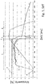
Fig. 1 zeigt beispielhafte gemessene Verläufe von Antriebsmoment, Zwischenkreisspannung und Bewegungsgeschwindigkeit eines beispielhaften Lagerbediengeräts nach dem Stand der Technik im Fall eines Netzausfalls. -
Fig. 2 zeigt entsprechende Messdaten bei der Durchführung eines erfindungsgemäßen Verfahrens zur Steuerung des Lagerbediengeräts. -
Fig. 3 zeigt entsprechende Messdaten bei der Durchführung eines alternativen erfindungsgemäßen Verfahrens mit einem kurzzeitig überhöhten Vorsteuerwert für das Antriebsmoment.
-
Fig. 1 shows exemplary measured courses of drive torque, DC link voltage and moving speed of an exemplary storage and retrieval device according to the prior art in the event of a power failure. -
Fig. 2 shows corresponding measurement data when carrying out a method according to the invention for controlling the storage and retrieval device. -
Fig. 3 shows corresponding measurement data in the implementation of an alternative method according to the invention with a temporarily excessive pilot value for the drive torque.
In den in den Figuren dargestellten Messungen sind die Messwerte als dimensionslose Relativwerte eines jeweiligen Referenzwerts angegeben. Die absoluten Messwerte sind für das Verständnis der vorliegenden Erfindung nicht wesentlich. Daher wurden für die einzelnen gemessenen Parameter mit entsprechenden Referenzwerten relative Messwerte gebildet, um die einzelnen Datenverläufe grafisch in sinnvoller Weise mit einer gemeinsamen Skalierung darstellen zu können.In the measurements shown in the figures, the measured values are given as dimensionless relative values of a respective reference value. The absolute measurements are not essential to the understanding of the present invention. Therefore, relative measured values were formed for the individual measured parameters with corresponding reference values in order to be able to display the individual data graphs in a meaningful way with a common scaling.
Die
Im Fall der
Zum Zeitpunkt des Netzausfalls 6 ändert sich der Verlauf aller drei gemessener Parameter signifikant. Während des Zeitraums der kurzen Phase 7 unmittelbar nach dem Zeitpunkt des Netzausfalls fällt die Zwischenkreisspannung 3 infolge der Entleerung des Zwischenkreises auf einen Restspannungswert ab. Nach diesem abrupten Spannungsabfall kann vom Zwischenkreis praktisch keine Energie mehr in den Antrieb gespeist werden, was sich darin äußert, dass das Antriebsmoment 2 während der Netzausfallphase 7 auf Null abfällt. Die Bewegungsgeschwindigkeit des Antriebs steigt nach dem Netzausfall nicht weiter an, sondern bleibt im gezeigten Beispiel im Rahmen von Messgenauig-keitsschwankungen zunächst noch annähernd konstant. Dies liegt an der Trägheit des in Bewegung befindlichen mechanischen Systems.At the time of
An die Netzausfallphase 7 schließt sich die Bremsphase 8 an. In dieser wirkt kein messbares Antriebsmoment 2 mehr. Die Zwischenkreisspannung 3 baut sich ausgehend von einem für die Speisung des Antriebs nicht mehr ausreichenden Restspannungswert allmählich weiter ab. Die Antriebsgeschwindigkeit 1 bleibt zunächst aufgrund der Trägheit zunächst noch weiter relativ konstant, bis die Bremse des Lagerbediengeräts, die aufgrund des nach herkömmlichen Methoden detektierten Netzausfalls aktiviert worden ist, schließt und durch die einsetzende Bremswirkung einen vergleichsweise steilen Abfall der Antriebsgeschwindigkeit 1 auf Null bewirkt. Im gezeigten Beispiel vergehen vom Einsetzen der Bremswirkung bis zum Still-stand des Antriebs ca. 150 ms.At the power failure phase 7, the
In
An den Zeitpunkt des Netzausfalls 6 schließt sich im gezeigten Beispiel eine Reaktionsphase 9 an. In dieser Reaktionsphase bewirkt die Steuereinrichtung beim Erkennen des Netzausfalls in vorteilhafter Weise eine Umsteuerung des Antriebs. Diese wird im gezeigten Beispiel in vorteilhafter Weise dadurch bewirkt, dass das Antriebsmoment 2 zunächst auf einen Vorsteuerwert von Null gesetzt und der Antrieb von einer motorischen in eine generatorische Betriebsphase umgesteuert wird. Das generatorische Antriebsmoment 2 - in
Durch das schnelle Umsteuern des Antriebs in die generatorische Betriebsweise fällt die Zwischenkreisspannung 3 lediglich minimal ab, bevor sie durch die vom Antrieb zurückgespeiste Energie wieder stabilisiert wird. Ab dem Moment des Umsteuerns beginnt infolgedessen eine Phase des stetigen Rückgangs der Antriebsgeschwindigkeit 1. Die Zwischenkreisspannung 3 wird in dieser Phase durch die vom generatorisch betriebenen Antrieb zurückgespeiste elektrische Energie aufrechterhalten. Im gezeigten Beispiel wird hierbei sogar eine Zwischenkreisspannung 3 über dem Niveau der Zwischenkreisspannung 3 im Netzbetrieb erreicht.Due to the rapid reversal of the drive in the regenerative mode of operation, the
Die Antriebsgeschwindigkeit 1 des Antriebs beginnt so bereits unmittelbar nach dem Zeitpunkt des Netzausfalls zu sinken. Im gezeigten Beispiel reduziert sich die Antriebsgeschwindigkeit 1 und damit die Bewegungsgeschwindigkeit des Lagerbediengeräts über einen Zeitraum von ca. 500 ms auf Null. Auf diese Weise wird ein signifikant sanfteres Stillsetzen des Lagerbediengeräts erreicht als nach dem in
Im Fall der in
Unmittelbar danach wird das nun generatorische bzw. bremsende Antriebsmoment 2 dann im gezeigten Beispiel auf den Startwert einer Rampe eingestellt. Dieser Startwert entspricht einem niedrigeren Bremsmoment als der überhöhte Vorsteuerwert. Danach wird das Bremsmoment - ähnlich wie zu
In diesem Fall kommt das Lagerbediengerät in einem Zeitraum von ca. 400 ms zum Stillstand, d.h. die Dauer des Verzögerungsvorgangs wird durch den kurzzeitig überhöhten Vorsteuerwert (und den resultierenden Drehmoment-Boost) aufgrund des schnelleren Umkommutierens verkürzt. Gleichzeitig wird vor Allem zu Beginn des generatorischen Bremsvorgangs unmittelbar nach dem Zeitpunkt des Netzausfalls 6, also bereits zu Beginn der Reaktionsphase, mehr elektrische Energie vom Antrieb in den Zwischenkreis zurückgespeist als im Fall der in
- 11
- Antriebsgeschwindigkeitdriving speed
- 22
- Antriebsmomentdrive torque
- 33
- ZwischenkreisspannungIntermediate circuit voltage
- 44
- StartzeitpunktStart time
- 55
- Beschleunigungsphaseacceleration phase
- 66
- Zeitpunkt des NetzausfallsTime of the power failure
- 77
- Phase unmittelar nach NetzausfallPhase immediately after power failure
- 88th
- Bremsphasebraking phase
- 99
- Reaktionsphasereaction phase
Claims (10)
dadurch gekennzeichnet,
dass die Steuereinrichtung zum Erkennen eines Netzausfalls des Energieversorgungsnetzes Mittel zur Überwachung der Zwischenkreisspannung (3) in dem Zwischenkreis aufweist.Storage operating device with a drive which is supplied via a converter with electrical energy from a power supply network, wherein the converter has an electrical intermediate circuit, wherein the storage control device has a control device which is adapted to detect a power failure and to respond to this
characterized,
that the control device has in the intermediate circuit for detecting a power failure of the power supply system means for monitoring the intermediate circuit voltage (3).
dadurch gekennzeichnet,
dass das Lagerbediengerät eine aus dem Zwischenkreis gespeiste Energieversorgungseinrichtung, insbesondere ein Weitbereichsnetzteil, zur Versorgung der Steuereinrichtung und/oder einer elektromechanischen Bremse des Lagerbediengerätes mit elektrischer Energie aufweist.Storage and retrieval device according to claim 1,
characterized,
that the storage and retrieval unit has a powered from the intermediate circuit power supply device, in particular a wide range power supply, for supplying the control device and / or an electro-mechanical brake of the storage and retrieval unit with electrical energy.
dadurch gekennzeichnet,
dass die Steuereinrichtung die Zwischenkreisspannung (3) eines Zwischenkreises eines Umrichters überwacht und zur Erkennung von Netzausfällen nutzt.Method for controlling a storage and retrieval device, in particular a storage and retrieval device according to one of the preceding claims, wherein a control device recognizes and reacts to network failures during operation of the storage and retrieval device,
characterized,
that the control device monitors the DC link voltage (3) of an intermediate circuit of a converter and uses for detecting network failures.
dadurch gekennzeichnet,
dass zur Erkennung eines Netzausfalls die Unterschreitung eines Schwellenwertes durch die, insbesondere ungeglättete, Zwischenkreisspannung (3) genutzt wird.Method according to claim 3,
characterized,
that for the recognition of a power failure the undershooting of a threshold value by the particular unsmoothed DC voltage (3) is used.
dadurch gekennzeichnet,
dass die Höhe des Schwellenwertes während des Betriebs des Lagerbediengeräts aus einer Referenzspannung gebildet wird, die aus der geglätteten Zwischenkreisspannung (3) gewonnen wird.Method according to claim 4,
characterized,
that the height of the threshold value during operation of the storage and retrieval device is formed from a reference voltage which is obtained from the smoothed intermediate circuit voltage (3).
dadurch gekennzeichnet,
dass der Wert der Referenzspannung auf eine obere Grenzreferenzspannung begrenzt wird.Method according to claim 5,
characterized,
that the value of the reference voltage is limited to an upper limit reference voltage.
dadurch gekennzeichnet,
dass die Steuereinrichtung beim Erkennen eines Netzausfalls, insbesondere während einer Betriebsphase in der der Antrieb elektrische Energie in mechanische Energie umwandelt, das Lagerbediengerät in eine Betriebsphase, in der der Antrieb mechanische Energie in elektrische Energie umwandelt, umsteuert.Method according to one of claims 3 to 6,
characterized,
that the control device upon detection of a power failure, in particular during an operating phase in which the drive converts electrical energy into mechanical energy, the storage and retrieval device in an operating phase in which the drive converts mechanical energy into electrical energy, reverses.
dadurch gekennzeichnet,
dass das Umsteuern, insbesondere unter Umgehung einer Drehzahlregelung, durch Einstellung eines vorgegebenen, insbesondere von der Steuereinrichtung aus einem Datenspeicher abrufbaren, Vorsteuerwerts für das Antriebsmoment erfolgt, insbesondere wobei kurzzeitig ein überhöhter Wert eingestellt wird, der anschließend wieder abgesenkt wird.Method according to claim 7,
characterized,
that the reversing, in particular bypassing a speed control by setting a predetermined, in particular wherein a short time, an excessive value is set, which is then lowered again retrievable in particular by the control device from a data memory, is performed pilot value for the driving torque.
dadurch gekennzeichnet,
dass die Steuereinrichtung beim Erkennen während einer und/oder nach dem Umsteuern in eine Betriebsphase, in der der Antrieb mechanische Energie in elektrische Energie umwandelt, das Abbremsen der Bewegung des Lagerbediengeräts durch den Antrieb, vorzugsweise mit einem zeitabhängig ansteigenden Antriebsmoment, herbeiführt.Method according to one of claims 3 to 8,
characterized,
that the control device during detection during and / or after the reversal in an operating phase in which the drive converts mechanical energy into electrical energy, the braking of the movement of the storage and retrieval device by the drive, preferably with a time-increasing drive torque, causes.
dadurch gekennzeichnet,
dass die Steuereinrichtung nach dem Erkennen eines Netzausfalls eine Bremse des Lagerbediengeräts aktiviert, sobald eine vorgebbare Grenzgeschwindigkeit des Lagerbediengeräts unterschritten wird.Method according to one of claims 3 to 9,
characterized,
that the control device activates a brake of the storage and retrieval device after detecting a power failure as soon as a predefinable limit speed of the storage and retrieval device is exceeded.
Applications Claiming Priority (1)
| Application Number | Priority Date | Filing Date | Title |
|---|---|---|---|
| DE102016010327.2A DE102016010327A1 (en) | 2016-08-29 | 2016-08-29 | Storage operating device and method for controlling a storage and retrieval device |
Publications (2)
| Publication Number | Publication Date |
|---|---|
| EP3291028A1 true EP3291028A1 (en) | 2018-03-07 |
| EP3291028B1 EP3291028B1 (en) | 2024-03-13 |
Family
ID=59745153
Family Applications (1)
| Application Number | Title | Priority Date | Filing Date |
|---|---|---|---|
| EP17185414.4A Active EP3291028B1 (en) | 2016-08-29 | 2017-08-08 | Storage handling device and method for controlling the storage handling device |
Country Status (3)
| Country | Link |
|---|---|
| US (1) | US10775864B2 (en) |
| EP (1) | EP3291028B1 (en) |
| DE (1) | DE102016010327A1 (en) |
Families Citing this family (1)
| Publication number | Priority date | Publication date | Assignee | Title |
|---|---|---|---|---|
| EP3629469A1 (en) | 2018-09-28 | 2020-04-01 | Siemens Aktiengesellschaft | Belt conveyor device and method for stopping a belt of a belt conveyor device |
Citations (3)
| Publication number | Priority date | Publication date | Assignee | Title |
|---|---|---|---|---|
| US5917297A (en) * | 1996-07-25 | 1999-06-29 | Lust Antriebstechnik Gmbh | Arrangement and method for operating a magnetically suspended, electromotoric drive apparatus in the event of a mains disturbance |
| US20130151199A1 (en) * | 2011-12-07 | 2013-06-13 | Steven Ross Hadley | Systems and methods for use in monitoring an industrial facility |
| DE102014220165A1 (en) | 2014-10-06 | 2016-04-07 | Viastore Systems Gmbh | Storage and retrieval unit and method for controlling a storage and retrieval unit |
Family Cites Families (9)
| Publication number | Priority date | Publication date | Assignee | Title |
|---|---|---|---|---|
| JP2002362710A (en) | 2001-06-04 | 2002-12-18 | Murata Mach Ltd | Running carrier |
| US20060129374A1 (en) * | 2004-12-15 | 2006-06-15 | Larson Lee A | Apparatus and method for apparatus mediating voltage levels between an emulation unit and a target processor |
| DE102006015031A1 (en) * | 2006-03-31 | 2007-10-11 | Siemens Ag | Method for reducing the reactive power demand of a fundamental-frequency switched line-side converter during idling and at low motor load |
| JP5527995B2 (en) | 2009-03-31 | 2014-06-25 | 株式会社Ihiインフラシステム | Load drive device |
| DE102009017023A1 (en) * | 2009-04-14 | 2010-10-28 | Siemens Aktiengesellschaft | Drive system for a system with an AC island network |
| DE102013226763A1 (en) * | 2013-12-19 | 2015-06-25 | Bayerische Motoren Werke Aktiengesellschaft | Safety circuit arrangement for an electric drive unit |
| JP5836510B1 (en) * | 2014-01-10 | 2015-12-24 | 株式会社日立産機システム | Power converter |
| JP6377985B2 (en) * | 2014-07-24 | 2018-08-22 | ファナック株式会社 | Motor control device with torque command limiting function during power failure |
| JP6356716B2 (en) * | 2016-02-29 | 2018-07-11 | ファナック株式会社 | Motor control device having torque command limiter |
-
2016
- 2016-08-29 DE DE102016010327.2A patent/DE102016010327A1/en active Pending
-
2017
- 2017-08-08 EP EP17185414.4A patent/EP3291028B1/en active Active
- 2017-08-11 US US15/674,760 patent/US10775864B2/en active Active
Patent Citations (3)
| Publication number | Priority date | Publication date | Assignee | Title |
|---|---|---|---|---|
| US5917297A (en) * | 1996-07-25 | 1999-06-29 | Lust Antriebstechnik Gmbh | Arrangement and method for operating a magnetically suspended, electromotoric drive apparatus in the event of a mains disturbance |
| US20130151199A1 (en) * | 2011-12-07 | 2013-06-13 | Steven Ross Hadley | Systems and methods for use in monitoring an industrial facility |
| DE102014220165A1 (en) | 2014-10-06 | 2016-04-07 | Viastore Systems Gmbh | Storage and retrieval unit and method for controlling a storage and retrieval unit |
Also Published As
| Publication number | Publication date |
|---|---|
| DE102016010327A1 (en) | 2018-03-01 |
| US10775864B2 (en) | 2020-09-15 |
| US20180059760A1 (en) | 2018-03-01 |
| EP3291028B1 (en) | 2024-03-13 |
Similar Documents
| Publication | Publication Date | Title |
|---|---|---|
| DE102015108889B4 (en) | Motor control device with protection unit of a charging resistor | |
| DE102017008916A1 (en) | Production system for performing cooperative work by an operator and a robot | |
| EP2542456B1 (en) | Method for carrying out an emergency braking operation | |
| DE102016110370A1 (en) | SERVO MOTOR STOP CONTROL TO CONTROL AND STOP A SERVO MOTOR DURING AN EMERGENCY STOP | |
| EP3017917B1 (en) | Method and system for stopping axles of an industrial robot | |
| DE102010044644A1 (en) | Method for collision detection for a drive unit | |
| DE102014116257A1 (en) | Motor control for protection of the tool and the object to be processed during a quick stop | |
| EP2887535A1 (en) | Drive and control system for raising gates | |
| DE102015210431A1 (en) | Method for controlling a parking brake in a vehicle | |
| EP2701299A1 (en) | Method and device for the intermediate storage of electrical energy | |
| EP1602014B1 (en) | Method and device for controlling a door/gate drive | |
| DE102010023536A1 (en) | Smart net capacity control device for automatic control engineering device e.g. press device, has flywheel energy storage provided with electromotor, and processor reading received information with rotation speed of flywheel energy storage | |
| DE102009035449B3 (en) | Method and device for time-controlled pinch detection | |
| EP3291028B1 (en) | Storage handling device and method for controlling the storage handling device | |
| EP2914533B1 (en) | Device for preventing the excess speed of a door leaf caused by a power storage device | |
| WO2018224643A1 (en) | Control device, goods transport conveyor, and method for controlling a goods transport conveyor | |
| EP2175552A1 (en) | Method for operating a drive device and drive device for implementing the method | |
| EP3465899B1 (en) | Controller and method for controlling a drive motor of a product conveyor belt at a checkout | |
| DE102016114038B4 (en) | servo motor control device | |
| DE102018105681A1 (en) | Method for controlling a stacker crane | |
| DE102011083574A1 (en) | Method and device for moving a material web | |
| DE10254608B4 (en) | drive system | |
| DE102017204123A1 (en) | Method for braking a machine and a machine | |
| AT515985A1 (en) | Power supply device | |
| EP3438772A1 (en) | Overrun measurement including readjustment as regards brake control for press control units |
Legal Events
| Date | Code | Title | Description |
|---|---|---|---|
| PUAI | Public reference made under article 153(3) epc to a published international application that has entered the european phase |
Free format text: ORIGINAL CODE: 0009012 |
|
| STAA | Information on the status of an ep patent application or granted ep patent |
Free format text: STATUS: THE APPLICATION HAS BEEN PUBLISHED |
|
| AK | Designated contracting states |
Kind code of ref document: A1 Designated state(s): AL AT BE BG CH CY CZ DE DK EE ES FI FR GB GR HR HU IE IS IT LI LT LU LV MC MK MT NL NO PL PT RO RS SE SI SK SM TR |
|
| AX | Request for extension of the european patent |
Extension state: BA ME |
|
| STAA | Information on the status of an ep patent application or granted ep patent |
Free format text: STATUS: REQUEST FOR EXAMINATION WAS MADE |
|
| 17P | Request for examination filed |
Effective date: 20180904 |
|
| RBV | Designated contracting states (corrected) |
Designated state(s): AL AT BE BG CH CY CZ DE DK EE ES FI FR GB GR HR HU IE IS IT LI LT LU LV MC MK MT NL NO PL PT RO RS SE SI SK SM TR |
|
| STAA | Information on the status of an ep patent application or granted ep patent |
Free format text: STATUS: EXAMINATION IS IN PROGRESS |
|
| 17Q | First examination report despatched |
Effective date: 20210528 |
|
| STAA | Information on the status of an ep patent application or granted ep patent |
Free format text: STATUS: EXAMINATION IS IN PROGRESS |
|
| GRAP | Despatch of communication of intention to grant a patent |
Free format text: ORIGINAL CODE: EPIDOSNIGR1 |
|
| STAA | Information on the status of an ep patent application or granted ep patent |
Free format text: STATUS: GRANT OF PATENT IS INTENDED |
|
| INTG | Intention to grant announced |
Effective date: 20230925 |
|
| GRAS | Grant fee paid |
Free format text: ORIGINAL CODE: EPIDOSNIGR3 |
|
| GRAA | (expected) grant |
Free format text: ORIGINAL CODE: 0009210 |
|
| STAA | Information on the status of an ep patent application or granted ep patent |
Free format text: STATUS: THE PATENT HAS BEEN GRANTED |
|
| AK | Designated contracting states |
Kind code of ref document: B1 Designated state(s): AL AT BE BG CH CY CZ DE DK EE ES FI FR GB GR HR HU IE IS IT LI LT LU LV MC MK MT NL NO PL PT RO RS SE SI SK SM TR |
|
| REG | Reference to a national code |
Ref country code: GB Ref legal event code: FG4D Free format text: NOT ENGLISH |
|
| REG | Reference to a national code |
Ref country code: CH Ref legal event code: EP |
|
| REG | Reference to a national code |
Ref country code: DE Ref legal event code: R096 Ref document number: 502017015919 Country of ref document: DE |