EP3291021A1 - Fixing belt and fixing apparatus - Google Patents
Fixing belt and fixing apparatus Download PDFInfo
- Publication number
- EP3291021A1 EP3291021A1 EP17183252.0A EP17183252A EP3291021A1 EP 3291021 A1 EP3291021 A1 EP 3291021A1 EP 17183252 A EP17183252 A EP 17183252A EP 3291021 A1 EP3291021 A1 EP 3291021A1
- Authority
- EP
- European Patent Office
- Prior art keywords
- belt
- heat generation
- metal layer
- layer
- thickness
- Prior art date
- Legal status (The legal status is an assumption and is not a legal conclusion. Google has not performed a legal analysis and makes no representation as to the accuracy of the status listed.)
- Withdrawn
Links
Images




Classifications
-
- G—PHYSICS
- G03—PHOTOGRAPHY; CINEMATOGRAPHY; ANALOGOUS TECHNIQUES USING WAVES OTHER THAN OPTICAL WAVES; ELECTROGRAPHY; HOLOGRAPHY
- G03G—ELECTROGRAPHY; ELECTROPHOTOGRAPHY; MAGNETOGRAPHY
- G03G15/00—Apparatus for electrographic processes using a charge pattern
- G03G15/20—Apparatus for electrographic processes using a charge pattern for fixing, e.g. by using heat
- G03G15/2003—Apparatus for electrographic processes using a charge pattern for fixing, e.g. by using heat using heat
- G03G15/2014—Apparatus for electrographic processes using a charge pattern for fixing, e.g. by using heat using heat using contact heat
- G03G15/2017—Structural details of the fixing unit in general, e.g. cooling means, heat shielding means
-
- G—PHYSICS
- G03—PHOTOGRAPHY; CINEMATOGRAPHY; ANALOGOUS TECHNIQUES USING WAVES OTHER THAN OPTICAL WAVES; ELECTROGRAPHY; HOLOGRAPHY
- G03G—ELECTROGRAPHY; ELECTROPHOTOGRAPHY; MAGNETOGRAPHY
- G03G15/00—Apparatus for electrographic processes using a charge pattern
- G03G15/20—Apparatus for electrographic processes using a charge pattern for fixing, e.g. by using heat
- G03G15/2003—Apparatus for electrographic processes using a charge pattern for fixing, e.g. by using heat using heat
- G03G15/2014—Apparatus for electrographic processes using a charge pattern for fixing, e.g. by using heat using heat using contact heat
- G03G15/2053—Structural details of heat elements, e.g. structure of roller or belt, eddy current, induction heating
- G03G15/2057—Structural details of heat elements, e.g. structure of roller or belt, eddy current, induction heating relating to the chemical composition of the heat element and layers thereof
Definitions
- Embodiments described herein relate generally to a fixing belt and a fixing apparatus.
- an image forming apparatus such as a multi-function peripheral (hereinafter, referred to as an "MFP") and a printer.
- the image forming apparatus is equipped with a fixing apparatus.
- the fixing apparatus heats a conductive layer of a belt through an electromagnetic induction heating system (hereinafter, referred to as an "IH system”) .
- IH system electromagnetic induction heating system
- the fixing apparatus fixes a toner image on an image receiving medium through the heat of the belt.
- the conductive layer of the belt generates the heat through induced current.
- the fixing apparatus reduces an amount of energy consumption without heating the belt in a case in which the fixing apparatus is in a dormant state in which a fixing processing is not executed.
- the fixing apparatus reduces heat capacity of the belt to shorten the time required for the fixing apparatus to transform from the dormant state to the start of forming an image.
- the fixing apparatus is equipped with a magnetic material so as to compensate the lack of calorific value of the belt.
- the magnetic material concentrates magnetic flux at the time of electromagnetic induction heating to increase the calorific value of the belt.
- the magnetic material is a magnetic shunt alloy.
- a technology for forming a part of the conductive layer with a non-magnetic metal there is known a technology for forming a part of the conductive layer with a non-magnetic metal.
- the temperature of the magnetic shunt alloy is undesirably increased.
- the belt may not be sufficiently heated in some cases.
- such a fixing apparatus cannot shorten the time required to transform from the dormant state to the start of forming an image.
- One of the objects of the present invention is to improve prior art techniques and overcome at least some of the prior art problems as for instance the problem(s) above illustrated.
- the object is achieved by the subject matter of the independent claims.
- Advantageous embodiments are provided according to the subject matter of the dependent claims. Further examples are provided to facilitate the understanding of the invention.
- a fixing belt for an image forming apparatus comprising: a non-magnetic metal layer; and a magnetic metal layer, wherein a thickness of the magnetic metal layer is larger than a thickness of the non-magnetic metal layer.
- an image forming apparatus comprising the fixing belt according to the above first aspect.
- a fixing apparatus comprising: a fixing belt comprising a non-magnetic metal layer and a magnetic metal layer, wherein a thickness of the magnetic metal layer is larger than a thickness of the non-magnetic metal layer.
- an image forming apparatus comprising the fixing apparatus according to the above third aspect.
- a fixing belt has a non-magnetic metal layer and a magnetic metal layer.
- the thickness of the magnetic metal layer is larger than that the thickness of the non-magnetic metal layer.
- Fig. 1 is a side view illustrating an image forming apparatus 10 according to a first embodiment.
- an MFP 10 is described as an example of the image forming apparatus 10.
- the MFP 10 is equipped with a scanner 12, a control panel 13 and a main body section 14. Each of the scanner 12, the control panel 13 and the main body section 14 comprises a control section.
- the MFP 10 comprises a system control section 100 serving as a control section for collectively controlling each control section.
- the system control section 100 includes a CPU (Central Processing Unit) 100a, a ROM (Read Only Memory) 100b and a RAM (Random Access Memory) 100c (refer to Fig. 4 ).
- CPU Central Processing Unit
- ROM Read Only Memory
- RAM Random Access Memory
- the system control section 100 controls a main body control circuit 101 (refer to Fig. 2 ) serving as a control section of the main body section 14.
- the main body control circuit 101 comprises a CPU, a ROM and a RAM (none is shown) .
- the main body section 14 is equipped with a paper feed cassette section 16, a printer section 18 and a fixing apparatus 34.
- the main body control circuit 101 controls the paper feed cassette section 16, the printer section 18 and the fixing apparatus 34.
- the scanner 12 reads an image of a document.
- the control panel 13 is equipped with input keys 13a and a display section 13b.
- the input keys 13a receive an input from a user.
- the display section 13b is a touch panel type.
- the display section 13b receives the input from the user to display information to the user.
- the paper feed cassette section 16 comprises a paper feed cassette 16a and a pickup roller 16b.
- the paper feed cassette 16a stores sheets P serving as image receiving media.
- the pickup roller 16b picks up the sheet P from the paper feed cassette 16a.
- the paper feed cassette 16a feeds the sheet P that is not used.
- a paper feed tray 17 feeds the unused sheet P with a pickup roller 17a.
- the printer section 18 forms an image.
- the printer section 18 carries out an image forming processing on the image of document read by the scanner 12.
- the printer section 18 is equipped with an intermediate transfer belt 21.
- the printer section 18 supports the intermediate transfer belt 21 through a backup roller 40, a driven roller 41 and a tension roller 42.
- the backup roller 40 is equipped with a driving section (not shown).
- the printer section 18 rotates the intermediate transfer belt 21 in a direction indicated by an arrow m.
- the printer section 18 comprises four sets of image forming stations 22Y, 22M, 22C and 22K.
- the image forming stations 22Y, 22M, 22C and 22K are used to respectively form a Y (yellow) image, an M (magenta) image, a C (cyan) image and a K (black) image.
- the image forming stations 22Y, 22M, 22C and 22K are arranged in parallel to each other along a rotation direction of the intermediate transfer belt 21 below the intermediate transfer belt 21.
- the printer section 18 is equipped with cartridges 23Y, 23M, 23C and 23K respectively above the image forming stations 22Y, 22M, 22C and 22K.
- the cartridges 23Y, 23M, 23C and 23K respectively store toner for replenishment of Y (yellow), M (magenta), C (cyan) and K (black) toner.
- the image forming station 22Y for forming the Y (yellow) image among the image forming stations 22Y, 22M, 22C and 22K is described as an example. Further, as the configurations of the image forming stations 22M, 22C and 22K are the same as the configuration of the image forming station 22Y, the detailed description thereof is omitted.
- the image forming station 22Y comprises a charger 26, an exposure scanning head 27, a developing device 28 and a photoconductive cleaner 29.
- the charger 26, the exposure scanning head 27, the developing device 28 and the photoconductive cleaner 29 are arranged around a photoconductive drum 24 rotating in a direction indicated by an arrow n.
- the image forming station 22Y includes a primary transfer roller 30.
- the primary transfer roller 30 faces the photoconductive drum 24 across the intermediate transfer belt 21.
- the image forming station 22Y exposes the photoconductive drum 24 that is charged by the charger 26 through the exposure scanning head 27.
- the image forming station 22Y forms an electrostatic latent image on the photoconductive drum 24.
- the developing device 28 develops the electrostatic latent image on the photoconductive drum 24 using a two-component developing agent including toner and carrier.
- the primary transfer roller 30 primarily transfers the toner image formed on the photoconductive drum 24 to the intermediate transfer belt 21.
- the image forming stations 22Y, 22M, 22C and 22K form a color toner image on the intermediate transfer belt 21 through the primary transfer roller 30.
- the color toner image is formed by overlapping toner images of Y (yellow), M (magenta), C (cyan) and K (black) in sequence.
- the photoconductive cleaner 29 removes the toner left on the photoconductive drum 24 after the primary transfer.
- the printer section 18 includes a secondary transfer roller 32.
- the secondary transfer roller 32 faces a backup roller 40 across the intermediate transfer belt 21.
- the secondary transfer roller 32 secondarily transfers the color toner image on the intermediate transfer belt 21 collectively to the sheet P.
- the sheet P is fed by the paper feed cassette section 16 or a manual paper feeding tray 17 along a conveyance path 33.
- the printer section 18 is equipped with a belt cleaner 43 facing a driven roller 41 across the intermediate transfer belt 21.
- the belt cleaner 43 removes the toner left on the intermediate transfer belt 21 after the secondary transfer.
- the printer section 18 is equipped with a register roller 33a, a fixing apparatus 34 and a sheet discharge roller 36 along the conveyance path 33.
- the printer section 18 includes a bifurcating section 37 and a reversal conveyance section 38 at the downstream side of the fixing apparatus 34.
- the bifurcating section 37 sends the sheet P subjected to a fixing processing to a sheet discharge section 20 or the reversal conveyance section 38.
- the reversal conveyance section 38 reverses the sheet P sent from the bifurcating section 37 to a direction of the register roller 33a and conveys it.
- the MFP 10 forms a fixed toner image on the sheet P with the printer section 18 and then discharges it to the sheet discharge section 20.
- the MFP 10 is not limited to the tandem developing system, and the number of the developing devices 28 is also not limited. Further, the MFP 10 may transfer the toner image from the photoconductive drum 24 to the sheet P directly.
- Fig. 2 is a side view containing an electromagnetic induction heating coil unit 52 and a control block of a main body control circuit 101.
- the electromagnetic induction heating coil unit is referred to as an "IH coil unit”.
- the fixing apparatus 34 is equipped with a belt 50 (fixing belt), a press roller 51, an IH coil unit 52, a heat generation assistance plate 69 (magnetic material), an insulating member 691 (sheet), a shield 76 and the main body control circuit 101.
- the fixing belt 50 is a cylindrical endless belt. On the inner peripheral surface of the fixing belt 50, a belt internal mechanism 55 including a nip pad 53 and the heat generation assistance plate 69 is arranged. In the present embodiment, the belt 50 contacts with the heat generation assistance plate 69.
- the fixing belt 50 is formed by laminating a heat generation layer 50a (conductive layer), a protective layer 50a1, an elastic layer 50d and a releasing layer 50c in sequence on a base layer 50b (refer to Fig. 3 and Fig. 5 ) . Further, as long as the fixing belt 50 includes the heat generation layer 50a and the protective layer 50a1, no limitation is given to the layer constitution.
- the base layer 50b is made from polyimide resin (PI).
- the heat generation layer 50a is formed by a non-magnetic metal such as copper (Cu) and becomes a main heat generation section in the belt 50.
- the protective layer 50a1 is formed by the magnetic metal such as nickel (Ni) .
- the releasing layer 50c is made from fluorine resin such as PFA (Tetrafluoroethylene Perfluoro alkyl vinyl ether copolymer resin) .
- the elastic layer 50d is formed by an elastic body such as silicone rubber.
- the shape of the belt 50 is not limited.
- the warming-up is a processing containing a processing of increasing the temperature of the belt 50 to a temperature at which a fixing processing is executable.
- the fixing belt 50 having low heat capacity shortens the time required in warming-up and saves energy consumption.
- the thickness of the copper layer of the heat generation layer 50a is equal to or smaller than 12 ⁇ m.
- the outer peripheral surface of the heat generation layer 50a is coated by the protective layer 50a1.
- the protective layer 50a1 can suppress the oxidation of the heat generation layer 50a.
- the protective layer 50a1 improves the mechanical strength of the fixing belt 50.
- the thickness of the protective layer 50a1 is described later.
- the heat generation layer 50a may be formed by performing copper plating after performing a surface treatment on the base layer 50b made from polyimide resin.
- the adhesion strength of the base layer 50b to the heat generation layer 50a is improved.
- the belt 50 improves the mechanical strength of the fixing belt 50.
- the surface of the base layer 50b may be roughened through sandblast or chemical etching. By roughening the surface of the base layer 50b, the belt 50 further mechanically improves the adhesion strength of the base layer 50b to the heat generation layer 50a.
- a metal such as titanium (Ti) may be dispersed into the polyimide resin to form the base layer 50b.
- Ti titanium
- the belt 50 further improves the adhesion strength of the base layer 50b to the heat generation layer 50a.
- the heat generation layer 50a may be made from non-magnetic metal such as aluminum (Al), copper (Cu) and silver (Ag) and the like.
- the heat generation layer 50a is not limited to non-magnetic pure metal and may be an alloy having non-magnetic properties.
- the heat generation layer 50a may be formed by combining two or more kinds of alloys or pure metals having the non-magnetic properties.
- the heat generation layer 50a may also be formed by overlapping two or more kinds of material selected from alloys or pure metals having the non-magnetic properties in a layered shape.
- the IH coil unit 52 is equipped with a main coil 56 and a core 57.
- the main coil 56 is formed by winding litz wire bundling a plurality of copper wire coated with heat-resistant polyamide-imide which is an insulating material.
- a high frequency current is applied to the main coil 56 from an inverter driving circuit 68. Through enabling the high frequency current to flow to the main coil 56, high frequency magnetic field is generated in the vicinity of the main coil 56.
- the core 57 becomes a magnetic path of the magnetic flux generated by the main coil 56.
- the core 57 has parts protruding to the belt 50 side.
- the protruding parts are arranged at a central part and ends of the core 57 along a circumferential direction of the belt 50.
- a core central protrusion 57b is arranged at the central part of the core 57 .
- Core end protrusions 57c are arranged at both ends of the core 57.
- the magnetic flux generated by the main coil 56 can efficiently head for the belt 50 side.
- the heat generation assistance plate 69 has a surface facing the belt 50.
- a width direction hereinafter, referred to as a "belt width direction"
- the heat generation assistance plate 69 is formed into an arc shape along the inner peripheral surface of the belt 50.
- the heat generation assistance plate 69 may be arc shape viewed from the belt width direction.
- the position of the heat generation assistance plate 69 is determined so that the arc-shape surface of the heat generation assistance plate 69 faces the belt 50.
- the heat generation assistance plate 69 faces the main coil 56 across the belt 50.
- the heat generation assistance plate 69 includes a magnetic material.
- the heat generation assistance plate 69 may be formed by thin member having magnetic properties such as iron (Fe), nickel (Ni) and stainless (SUS) .
- the stainless having the magnetic properties may be a magnetic SUS material such as SUS 420.
- the heat generation assistance plate 69 may be a sintered body of the magnetic material such as ferrite or be formed by resin in which the magnetic powder is dispersed as long as the heat generation assistance plate 69 has the magnetic properties.
- the heat generation assistance plate 69 is not limited to the thin plate member.
- the heat generation assistance plate 69 may also be formed by combining two or more types of different magnetic material.
- the heat generation assistance plate 69 is a magnetic shunt alloy (ferromagnetism body) of which the Curie point is lower than that of the heat generation layer 50a.
- magnetic shunt alloy ferrromagnetism body
- Two arc-shaped ends (upper end and lower end) of the heat generation assistance plate 69 are supported by a foundation (not shown) .
- the heat generation assistance plate 69 is pressed towards the belt 50.
- a lateral surface of the heat generation assistance plate 69 in a radial direction contacts the inner peripheral surface of the belt 50.
- the heat generation assistance plate 69 may be close to /away from the belt 50.
- the belt internal mechanism 55 may enable the lateral surface of the heat generation assistance plate 69 in the radial direction to separate from the inner peripheral surface of the belt 50 at the time of warming up the fixing apparatus 34.
- Fig. 3 is a view illustrating the magnetic paths to the belt 50 and the heat generation assistance plate 69 by the magnetic flux of the main coil 56.
- the magnetic flux generated by the main coil 56 forms a first magnetic path 81 induced to the heat generation layer 50a of the belt 50.
- the first magnetic path 81 passes through a core 57 of the main coil 56 and the heat generation layer 50a of the belt 50.
- the magnetic flux generated by the main coil 56 forms a second magnetic path 82 induced to the heat generation assistance plate 69.
- the second magnetic path 82 is formed at a position adjacent to the first magnetic path 81 in a radial direction of the belt 50 .
- the second magnetic path 82 passes through the heat generation assistance plate 69 and the heat generation layer 50a.
- the surface of the heat generation assistance plate 69 at the belt 50 side is arranged to contact with the inner surface of the belt 50.
- the heat generation assistance plate 69 has a recess 69d recessed towards a shaft side of the belt 50.
- the recess 69d enables a part of the surface of the heat generation assistance plate 69 facing the belt 50 to separate from the inner surface of the belt 50.
- the recess 69d is arranged at a position facing the core central protrusion 57b in the IH coil unit 52.
- the width of the recess 69d has length corresponding to the width of the core central protrusion 57b.
- the recess 69d and the core central protrusion 57b are arranged to face each other. In this way, the distance from the core central protrusion 57b to the heat generation assistance plate 69 is longer than that in a case in which there is no recess 69d. As a result, the magnetic flux in the vicinity of the core central protrusion 57b is difficult to decay compared with the case where there is no recess 69d.
- the IH coil unit 52 can efficiently form the first magnetic path 81 due to the generated magnetic flux.
- the recess area may be configured as space without providing filler in a recess of the recess 69d.
- an elastic body 69s for holding lubricating oil such as silicone oil may be arranged in the recess 69d.
- the elastic body 69s is arranged to contact with the inner peripheral surface of the belt 50. Through the rotation of the belt 50, the inner peripheral surface of the belt 50 is coated by the lubricating oil. Through the lubricating oil, frictional resistance of sliding contact between the belt 50 and the heat generation assistance plate 69 is reduced. Through the lubricating oil existing between the belt 50 and the heat generation assistance plate 69, it is possible to reduce the thermal resistance between the belt 50 and the heat generation assistance plate 69.
- the heat generation assistance plate 69 may be magnetic material of which the Curie point is lower than that of the heat generation layer 50a of the belt 50 as stated above.
- the heat generation assistance plate 69 is formed by a thin metal member made from the magnetic shunt alloy such as iron or nickel alloy the Curie point of which is 220 degrees centigrade-230degrees centigrade.
- the magnetism of the heat generation assistance plate 69 changes from the ferromagnetism to the paramagnetism if the temperature exceeds the Curie point thereof. If the temperature of the heat generation assistance plate 69 exceeds the Curie point, the second magnetic path 82 is not formed, thereby not assisting the heating of the belt 50 .
- the heat generation assistance plate 69 can assist rise of the temperature of the belt 50 at the time of a low temperature and suppress excessive rise of the temperature of the belt 50 at the time of a high temperature.
- a shield 76 is arranged at the inner peripheral side of the heat generation assistance plate 69 along the inner peripheral surface thereof.
- the shield 76 has a substantially arc-shape surface viewed from the belt width direction similar to the heat generation assistance plate 69.
- the shield 76 may be a substantially arc shape viewed from the belt width direction.
- Two arc-shaped ends of the shield 76 are supported by a foundation (not shown).
- the shield 76 may support the heat generation assistance plate 69.
- the shield 76 is formed by a non-magnetic material such as aluminum and copper. The shield 76 shields the magnetic flux from the IH coil unit 52.
- the shield 76 has a recess 76d recessed towards a shaft side of the belt 50.
- the recess 76d enables a part of the shield 76 to separate from the inner surface of the belt 50.
- the recess 76d is arranged at a position facing the core central protrusion 57b in the IH coil unit 52 similar to the recess 69d.
- the width of the recess 76d corresponds to the width of the recess 69d.
- the recess 76d and the core central protrusion 57b are arranged to face each other.
- the distance from the core central protrusion 57b to the shield 76 is longer than that in a case in which there is no recess 76d.
- the shield 76 is arranged apart from the heat generation assistance plate 69 by sandwiching a heat insulating layer 69i therebetween.
- An insulating member 691 is arranged in the heat insulating layer 69i except for a range corresponding to the recess 69d of the heat generation assistance plate 69.
- the insulating member 691 is described in detail later.
- a heat pipe 69h is arranged corresponding to the recess 69d.
- the heat pipe 69h is arranged at the opposite side of the belt 50 with respect to the heat generation assistance plate 69, in other words, in a recess of the recess 76d at the back side of the heat generation assistance plate 69 viewed from the belt 50 side.
- the heat pipe 69h increases heat dissipation from the heat generation assistance plate 69 and increases the speed of decrease in temperature.
- a nip pad 53 is described. At the inner peripheral side of the belt 50, the nip pad 53 presses the inner peripheral surface of the belt 50 to the press roller 51 side.
- a nip 54 is formed between the belt 50 and the press roller 51.
- the nip pad 53 has a nip forming surface 53a between the belt 50 and the press roller 51. When viewed from the belt width direction, the nip forming surface 53a curves to form a convex towards the inner peripheral surface of the belt 50. When viewed from the belt width direction, the nip forming surface 53a curves along the outer peripheral surface of the press roller 51.
- the nip pad 53 is formed by elastic material such as silicon rubber and fluorine rubber.
- the nip pad 53 may be formed by heat-resistant resin.
- the heat-resistant resin is PI (polyimide resin), PPS (polyphenylene sulfide resin), PES (polyether sulphone resin), LCP (liquid crystal polymer) and PF (phenol resin) and the like.
- a sheet-like friction reducing member is arranged between the belt 50 and the nip pad 53.
- the friction reducing member is formed by a sheet member and the releasing layer having excellent sliding properties and good wear resistance.
- the friction reducing member is fixedly supported by the belt internal mechanism 55.
- the friction reducing member slidably contacts the inner peripheral surface of the belt 50 that is operating.
- the friction reducing member may be formed by the following sheet member with lubricity.
- the sheet member may be composed of glass fiber sheet impregnated with fluororesin.
- the press roller 51 is equipped with a silicone sponge and a silicone rubber layer having heat-resistance around a core metal thereof.
- a releasing layer is arranged on the surface of the press roller 51.
- the releasing layer is formed by the fluorine-based resin such as PFA resin.
- the press roller 51 pressurizes the belt 50 by a pressure mechanism 51a.
- one motor 51b (driving section) is arranged.
- the motor 51b is driven by a motor driving circuit 51c controlled by the main body control circuit 101.
- the motor 51b is connected with the press roller 51 via a first gear row (not shown) .
- the motor 51b is connected with a belt driving member via a second gear row and a one-way clutch (none is shown) .
- the press roller 51 rotates in an arrow q direction through the motor 51b. In a case in which the belt 50 abuts against the press roller 51, the belt 50 is driven by the press roller 51 to rotate in an arrow u direction.
- the belt 50 rotates in an arrow u direction through the motor 51b.
- the belt 50 may be separated from the press roller 51 and have a driving source thereof .
- teeth engaged with the gear are arranged at the ends of the belt 50 along a moving direction thereof, and the belt 50 is driven in response to rotation of the gear to be driven to rotate by a motor (not shown) .
- a center thermistor 61 and an edge thermistor 62 are arranged at the inner peripheral side of the belt 50.
- the center thermistor 61 and the edge thermistor 62 are used to measure the temperature of the belt 50.
- the measurement result of the temperature of the belt 50 is input to the main body control circuit 101.
- the center thermistor 61 is arranged at the inner side of the belt width direction.
- the edge thermistor 62 is arranged in the heating area of the IH coil unit 52 and the sheet non-passing area in the belt width direction.
- the main body control circuit 101 stops the output of the electromagnetic induction heating in a case in which the temperature of the belt 50 measured by the edge thermistor 62 is equal to or greater than a threshold value. By stopping the output of the electromagnetic induction heating when the temperature of the sheet non-passing area of the belt 50 excessively rises, the main body control circuit 101 prevents the damage of the belt 50.
- a thermistor 64 may be arranged in the heat generation assistance plate 69.
- the thermistor 64 measures the temperature of the heat generation assistance plate 69.
- the measurement result of the temperature of the heat generation assistance plate 69 is input to the main body control circuit 101.
- the main body control circuit 101 may enable the heat generation assistance plate 69 abut against the belt 50 if the temperature of the heat generation assistance plate 69 measured by the thermistor 64 is equal to or greater than the threshold value.
- the main body control circuit 101 controls an IH control circuit 67 according to the measurement result of the temperature of the belt 50 by the center thermistor 61 and the edge thermistor 62.
- the IH control circuit 67 controls the value of the high frequency current output by the inverter driving circuit 68 under the control of the main body control circuit 101.
- the temperature of the belt 50 is maintained in various control temperature ranges according to the output by the inverter driving circuit 68.
- the IH control circuit 67 is equipped with a CPU, a ROM and a RAM (none is shown).
- a thermostat 63 is arranged in the belt internal mechanism 55.
- the thermostat 63 functions as a safety device of the fixing apparatus 34.
- the thermostat 63 operates when the belt 50 generates abnormal heat and the temperature thereof rises to a cut-off threshold value. Through the operation of the thermostat 63, the current to the IH coil unit 52 is cut off. Through cutting off the current to the IH coil unit 52, the abnormal heat generation of the fixing apparatus 34 can be prevented.
- Fig. 4 is a block diagram illustrating the control of the IH coil unit 52 according to the first embodiment as a main body.
- the MFP 10 (refer to Fig. 1 ) is equipped with the system control section 100, the main body control circuit 101, an IH circuit 120 and the motor driving circuit 51c .
- the IH circuit 120 is equipped with a rectifying circuit 121, the IH control circuit 67, the inverter driving circuit 68 and a current measurement circuit 122.
- the current is input to the IH circuit 120 via a relay 112 from an alternating-current power supply 111.
- the IH circuit 120 rectifies the input current through the rectifying circuit 121 to supply the rectified current to the inverter driving circuit 68.
- the relay 112 cuts off the current from the alternating-current power supply 111.
- the inverter driving circuit 68 is equipped with a driver IC 68b of an IGBT (Insulated Gate Bipolar Transistor) element 68a.
- the IH control circuit 67 controls the driver IC 68b according to the measurement result of the temperature of the belt 50 by the center thermistor 61 and the edge thermistor 62.
- the IH control circuit 67 controls the driver IC 68b to control the output of the ICBT element 68a.
- the current measurement circuit 122 sends the measurement result of the output of the IGBT element 68a to the IH control circuit 67.
- the IH control circuit 67 controls the driver IC 68b to make the output of the IH coil unit 52 constant based on the measurement result of the output of the ICBT element 68a by the current measurement circuit 122.
- the main body control circuit 101 acquires the temperature of the belt 50 from the center thermistor 61 and the edge thermistor 62. In a case in which the belt 50 contacts the heat generation assistance plate 69, the belt temperature is substantially the same as the temperature of the heat generation assistance plate 69. Thus, through acquiring the belt temperature, the temperature of the heat generation assistance plate 69 may also be indirectly acquired. In the standby state, the main body control circuit 101 controls the frequency applied to the IH coil unit 52 based on the belt temperature to enable the IH output to approach to the target value. In a case in which the belt 50 does not contact the heat generation assistance plate 69, the belt temperature is different from the temperature of the heat generation assistance plate 69 in some cases. In this case, the main body control circuit 101 may acquire the temperature detected by the thermistor 64 as the temperature of the heat generation assistance plate 69.
- the standby state refers to a standby state in which the fixing apparatus 34 does not execute the fixing operation and is equivalent to a state in which the MFP 10 (refer to Fig. 1 ) does not receive the print request.
- the time required from the dormant state to the starting of forming an image refers to time required for the starting of the fixing apparatus 34 or recovery time from the dormant state (sleep state) .
- the time required from the dormant state to the starting of forming an image is referred to as the recovery time.
- the fixing apparatus 34 shortens the recovery time without increasing amount of the energy consumption. For example, the heat capacity of the belt 50 is reduced to increase temperature rising speed of the belt 50. If the heat capacity is reduced, the belt 50 cannot accumulate needed heat quantity.
- the heat capacity of the belt 50 is reduced, and the heating efficiency of the belt 50 is improved.
- the belt 50 is impossible to accumulate the heat quantity required for fixing operation due to reducing the heat capacity in some cases. In this case, fixing failure (low-temperature offset) may occur.
- the increasing of the temperature rising rate of the belt 50 and the accumulation of the heat quantity required for fixing operation by the belt become a trade-off.
- the fixing apparatus of a comparative embodiment that is capable of lowering the rotational speed of the belt 50 can lower the rotational speed of the belt 50 to avoid the occurrence of the above trade-off.
- the fixing apparatus of the comparative embodiment is difficult to shorten the recovery time.
- Fig. 5 is a diagram illustrating the configuration of the belt 50.
- the belt 50 is formed by sequentially stacking the heat generation layer 50a, the protective layer 50a1, the elastic layer 50d and the releasing layer 50c on the base layer 50b.
- An adhesive layer 50a2 made of nickel may be arranged between the base layer 50b and the heat generation layer 50a.
- the protective layer 50a1 functions to assist heat generation in addition to the calorific value of the heat generation layer 50a.
- the protective layer 50a1 has a protection function to protect the belt 50 by preventing oxidation of the surface of the heat generation layer 50a and a durability improvement function to improve the durability of the belt 50.
- the protective layer of the belt of the comparative embodiment has a protection function to protect the belt by preventing oxidation of the surface of the heat generation layer 50a and a durability improvement function to improve the durability of the belt 50.
- the thickness of the protective layer of the belt of the comparative embodiment is determined so as to make the protection function and the durability improvement function effective.
- the thickness of the protective layer 50a1 is determined so as to satisfy the following conditions.
- the thickness of the protective layer 50a1 is determined so as to make a heat generation holding function for assisting heat generation by the heat generation layer 50a, the protection function and the durability improvement function effective.
- the belt 50 and the heat generation assistance plate 69 are arranged to contact with each other or be away from each other by a distance at which they can heat each other.
- the heat generation assistance plate 69 and the shield 76 are arranged by sandwiching the heat insulating layer 69i.
- the heat insulating layer 69i is constituted so as to make the thermal resistance between the heat generation assistance plate 69 and the shield 76 relatively high.
- the heat insulating layer 69i may be an air layer formed by arranging the heat generation assistance plate 69 and the shield 76 at a predetermined distance.
- the heat insulating layer 69i is constituted so as to make the electrical resistance between the heat generation assistance plate 69 and the shield 76 relatively high.
- the heat insulating layer 69i insulates the space between the heat generation assistance plate 69 and the shield 76.
- air or other insulating members 691 may be filled between the heat generation assistance plate 69 and the shield 76.
- the insulating member 691 may, for example, sheet material containing polyimide (Kapton ® Technology, etc.) or aramid (Nomex ® Technology, etc.) as the material.
- the insulating member 691 may be formed as a film or a sheet in which fiber is woven. It is desired the thickness of the insulating member 691 in that case is from 0.1 mm to 0.5 mm.
- the heat insulating layer 69i which is formed by including the insulating member 691 is arranged.
- the apparent heat capacity of the belt 50 becomes small, and the heating efficiency of the belt 50 is improved.
- the MFP 10 that is placed in the dormant state at night and the like lowers the temperature of the belt 50 and the heat generation assistance plate 69 to a relatively low temperature.
- the heat insulating layer 69i is arranged and the heating efficiency described above is improved, and thus, initial heating shortage of the heat generation assistance plate 69 after the dormant state of the MFP 10 is released is compensated, which contributes to the shortening of the rise time from the dormant state the like.
- the heat generation assistance plate 69, the heat insulating layer 69i and the shield 76 are warmed to a relatively high temperature.
- the belt 50 receives the heat and the viscosity of lubricant (silicon oil) coating the inner surface of the belt 50 decreases.
- the thermal resistance between the belt 50 and the heat generation assistance plate 69 is lowered, and thermal conductivity between the belt 50 and the heat generation assistance plate 69 is increased.
- the thickness of the insulating member 691 is from 0.1 mm to 0.5 mm, the heat of the heat generation assistance plate 69 and the shield 76 can be used to stabilize the temperature of the belt 50.
- the apparent heat capacity of the belt 50 is increased, and the heat of the belt 50, the heat generation assistance plate 69 and the shield 76 can be effectively used, thereby achieving the effect of reducing the power consumption. Further, the printing speed can be accelerated in the foregoing state.
- the thickness of the heat insulating layer 69i or the insulating member 691 is equal to or greater than 0.5mm, the thermal resistance among the heat generation assistance plate 69, the heat insulating layer 69i and the shield 76 is increased, and the heat conduction is extremely bad. As a result, although the apparent heat capacity of the belt 50 is reduced and the rise time from the dormant state is shortened, the thickness of the heat insulating layer 69i or the insulating member 691 is not suitable for accelerating the print speed.
- Fig. 6 is a diagram illustrating a relation of the calorific value with respect to the thickness of the protective layer and the thickness of the heat generation layer.
- a case in which the nickel is applied to the material of the protective layer 50a1 and the copper is applied to the material of the heat generation layer 50a is exemplified.
- a case in which the magnetic shunt alloy is applied to the material of the heat generation assistance plate 69 and the aluminum is applied to the material of the shield 76 is shown.
- Fig. 6 shows results generated by analyzing the calorific value of the whole belt 50 through electromagnetic field analysis in a case of fixing the thickness of the nickel layer of the belt 50 to 8 ⁇ m and changing the thickness of the copper layer.
- the analysis results shown in Fig. 6 are generated in a case of respectively setting the thickness of the copper layer to 2 ⁇ m, 6 ⁇ m, 12 ⁇ m and 16 ⁇ m.
- the calorific value of the nickel layer increases as the thickness of the copper layer becomes thinner.
- the calorific value of the nickel layer and the copper layer and the calorific value of the whole belt 50 increase as the thickness of the copper layer becomes thinner.
- the thickness of the copper layer is too thin and exceeds a certain range, shielding effect of the magnetic flux by the copper layer is reduced and the magnetic flux reaching the heat generation assistance plate 69 (magnetic shunt alloy) is increased. In this way, the heat generation assistance plate 69 (magnetic shunt alloy) arranged at the inside of the belt 50 is easily heated. In this case, the temperature of the magnetic shunt alloy is raised, the magnetic properties of the magnetic shunt alloy are lost, and the calorific value by the magnetic flux is reduced. For example, if the thickness of the copper layer is equal to or lower than 8 ⁇ m, the heating efficiency of the belt 50 is poor and the temperature rise speed thereof is slow. In the foregoing case, it is desired that the thickness of the copper layer is at least 5 ⁇ m or more so that the temperature of the generation assistance plate 69 (magnetic shunt alloy) is prevented from exceeding the Curie temperature.
- the thickness of the nickel layer becomes thin, the durability of the belt 50 decreases.
- the thickness of the nickel layer is required to be 6 ⁇ m or more.
- the thicker the thickness of the nickel layer becomes the larger the heat capacity by the protective layer 50a1 becomes, and the slower the temperature rise of the belt 50 becomes. Consequently, the thickness of the nickel layer is required to be thinner than a predetermined thickness.
- the predetermined thickness is set to 12 ⁇ m, and the thickness of the nickel layer is equal to or smaller 12 ⁇ m serving as predetermined thickness.
- the thickness of the copper layer is determined as 6 ⁇ m, and the thickness of the nickel layer is determined as 10 ⁇ m, and then the effect of the belt 50 is evaluated.
- the belt of the comparative embodiment is obtained by setting the thickness of the copper layer to 10 ⁇ m and the thickness of the nickel layer to 8 ⁇ m.
- the MFP 10 is possible to increase the print speed by using the above the belt 50 compared with a case of using the belt of the comparative embodiment.
- the belt 50 can increase the independent temperature rise properties.
- the time required for the starting of the fixing apparatus 34 is shortened to be substantially equal to the temperature rising time of the belt 50 in a case of heating the belt 50 independently.
- Fig. 7 is a diagram illustrating the time of the starting of a fixing apparatus or a sleep state.
- the press roller 51 is maintained in a state separated from the belt 50. Further, the heat generation assistance plate 69 is maintained in a state separated from the belt 50.
- the fixing apparatus 34 is in the non-energized state (power off) or in the dormant state. If the belt 50 serving an object to be heated is in a non-contact state with the generation assistance plate 69, the heat quantity generated by the belt 50 itself is used to heat only the heat capacity of the belt 50. In other words, the heat quantity generated by the heating of the belt 50 is not conducted to other objects and the belt 50 is rapidly heated.
- the heat generation assistance plate 69 is maintained in a state separated from the belt 50.
- the eddy current is generated by the magnetic flux penetrating the belt 50.
- the temperature of the heat generation assistance plate 69 is gradually increased through the self-heating by the eddy current.
- FIG. 8 is diagram illustrating operation sequence at the time of the starting of the fixing apparatus or at a recovery time from the sleep state.
- the system control section 100 detects an operation (referred to as a start-up operation) for instructing the starting (power on) or the recovery from the sleep state.
- the main body control circuit 101 starts (IH- > ON) heating by the IH coil unit 52 (ACT 11).
- the main body control circuit 101 acquires the temperature detected by the center thermistor 61 and the edge thermistor 62 after starting the heating operation (ACT 12A) .
- the main body control circuit 101 integrates the electric power required to enable the IH coil unit 52 to operate and heat the belt 50.
- the main body control circuit 101 acquires the integrated value as integrated power (ACT 12B).
- the main body control circuit 101 determines whether or not the temperature of the belt 50 reaches a predetermined temperature (A) after starting the heating operation (ACT 13) .
- the predetermined temperature (A) is a lower limit temperature of a temperature range to which the temperature of the belt 50 is independently increased until the press roller (PR) 51 is enabled to contact with the belt 50.
- the main body control circuit 101 enables the press roller (PR) 51 to contact with the belt 50 (ACT 14).
- the main body control circuit 101 determines whether or not the integrated value (integrated power) of the electric power consumed by heating the belt 50 exceeds a predetermined value (W) (ACT 15). If it is determined that the integrated power exceeds the predetermined value (W) (Yes in ACT 15), the main body control circuit 101 enables the heat generation assistance plate 69 to contact with the belt 50 (ACT 16).
- the main body control circuit 101 determines whether or not the temperature of the belt 50 reaches a Ready temperature (B) (ACT 17) .
- the Ready temperature (B) refers to a representative temperature of a temperature range at which the heating of the temperature of the belt 50 may be interrupted. For example, the Ready temperature (B) is set to a temperature higher than the predetermined temperature (A). If it is determined that the temperature of the belt 50 does not reach the Ready temperature (B) (No in ACT 17), the main body control circuit 101 repeats the processing subsequent to ACT 12A in the same way as stated above.
- the main body control circuit 101 stops (IH- > ON) the heating by the IH coil unit 52 (ACT 18) . After terminating a series of the processing relating to the start-up operation, the main body control circuit 101 enables the fixing apparatus 34 to be a standby state. Further, in the processing in ACT 18 described above, the main body control circuit 101 stops the heating by the IH coil unit 52; however, the following operation may be executed instead of that. For example, the main body control circuit 101 may reduce the current flowing to the IH coil unit 52 to reduce the calorific value of the belt 50.
- the main body control circuit 101 presumes the temperature of each section before the heat generation assistance plate 69 is enabled to contact with the belt 50 by taking the integrated value of the electric power required for the heating of the belt 50 as a reference.
- the main body control circuit 101 enables the heat generation assistance plate 69 to contact with the belt 50 after determining that the temperature of each section is in a desired temperature range. In this way, the main body control circuit 101 can manage the time required to increase the temperature of the belt 50.
- the main body control circuit 101 enables the heat generation assistance plate 69 to contact with the belt 50 after presuming that the temperature of each section is in a desired temperature range. In this way, the main body control circuit 101 can shorten the time required until the fixing apparatus 34 is recovered to a state in which an image can be formed by taking the integrated value of the electric power required for the heating of the belt 50 as a reference.
- the main body control circuit 101 according to the embodiment presumes the temperature of each section before the heat generation assistance plate 69 is enabled to contact with the belt 50 by taking the integrated value of the electric power required for the heating of the belt 50 as a reference. Instead, the main body control circuit 101 according to the modification presumes the temperature of each section before the heat generation assistance plate 69 is enabled to contact with the belt 50 by taking the temperature of the heat generation assistance plate 69 as a reference.
- the heat generation assistance plate 69 is equipped with the thermistor 64 for detecting the temperature of the heat generation assistance plate 69 .
- the main body control circuit 101 collects information of the temperature of the heat generation assistance plate 69 detected by the thermistor 64.
- Fig. 9 is diagram illustrating operation sequence at the time of the starting of a fixing apparatus or at a recovery time from a sleep state. The description thereof is executed by centering on points different from Fig. 8 .
- the system control section 100 detects an operation (referred to as a start-up operation) for instructing the starting (power on) or the recovery from the sleep state.
- the main body control circuit 101 starts (IH- > ON) heating by the IH coil unit 52 (ACT 11).
- the main body control circuit 101 acquires the temperature detected by the center thermistor 61 and the edge thermistor 62 after starting the heating operation (ACT 12A) .
- the main body control circuit 101 determines whether or not the temperature of the belt 50 reaches the predetermined temperature (A) (ACT 13). If it is determined that the temperature of the belt 50 reaches the predetermined temperature (A) (Yes in ACT 13), the main body control circuit 101 enables the press roller (PR) 51 to contact with the belt 50 (ACT 14).
- the main body control circuit 101 proceeds to the processing in ACT 15A.
- the main body control circuit 101 acquires the temperature of the heat generation assistance plate 69 detected by the thermistor 64 (ACT 15A) .
- the main body control circuit 101 determines whether or not the temperature of the heat generation assistance plate 69 exceeds a predetermined temperature (C) (ACT 15B). If it is determined that the temperature of the heat generation assistance plate 69 exceeds the predetermined temperature (C) (Yes in ACT 15B), the main body control circuit 101 enables the heat generation assistance plate 69 to contact with the belt 50 (ACT 16).
- the main body control circuit 101 proceeds to the processing in ACT 17 .
- the procedures after the processing in ACT 17 are the same as Fig. 8 .
- the main body control circuit 101 determines whether the temperature of each section is in a desired temperature range before the heat generation assistance plate 69 is enabled to contact with the belt 50 by taking the temperature of the heat generation assistance plate 69 as a reference.
- the main body control circuit 101 enables the heat generation assistance plate 69 to contact with the belt 50 after determining that the temperature of each section is in a desired temperature range. In this way, the main body control circuit 101 can manage the time required to increase the temperature of the belt 50 .
- the main body control circuit 101 enables the heat generation assistance plate 69 to contact with the belt 50 after presuming that the temperature of each section is in a desired temperature range.
- the main body control circuit 101 can shorten the time required until the fixing apparatus 34 is recovered to a state in which an image can be formed by taking the temperature of the heat generation assistance plate 69 as a reference.
- the belt 50 of the embodiment has at least the non-magnetic metal layer and a magnetic metal layer.
- the thickness of the magnetic metal layer is thicker than that of the non-magnetic metal layer.
- the thickness of the non-magnetic metal layer may be a range from 5 ⁇ m to 7 ⁇ m.
- the non-magnetic metal layer may be made of copper.
- the heat generation layer 50a is an example of the non-magnetic metal layer.
- the thickness of the magnetic metal layer may be a range from 6 ⁇ m to 12 ⁇ m.
- the magnetic metal layer may be made of nickel.
- the protective layer 50a1 is an example of the magnetic metal layer.
- the thickness of the magnetic metal layer is at least 10% thicker than the thickness of the non-magnetic metal layer. In another embodiment, the thickness of the magnetic metal layer is at least 25% thicker than the thickness of the non-magnetic metal layer. In yet another embodiment, the thickness of the magnetic metal layer is at least 50% thicker than the thickness of the non-magnetic metal layer.
- the fixing apparatus 34 of the embodiment has the belt 50. Furthermore, the fixing apparatus 34 may have a magnetic material the Curie temperature of which is from 200 degrees centigrade to 240 degrees centigrade. The magnetic material may have a surface facing the inner peripheral surface of the belt 50.
- the heat generation assistance plate 69 is an example of the magnetic material.
- the belt 50 is formed into layer shape and is formed by arranging the base layer (the base layer 50b), the magnetic metal layer and the non-magnetic metal layer in the order in a direction towards the outer peripheral side from the inner peripheral side of the belt 50.
- the magnetic material is located on the inner peripheral side with respect to these layers.
- the IH coil unit 52 is arranged at the outer peripheral side of the belt 50 and is an example of heating the belt 50 from the outer peripheral side.
- the IH coil unit 52 may be arranged at the inner peripheral side of the belt 50 to heat the belt 50 from the inner peripheral side. In this case, the IH coil unit 52 may heat a part where the belt 50 contacts with the press roller 51 from the inner peripheral side.
- a figure or a parameter from one range may be combined with another figure or a parameter from a different range for the same characteristic to generate a numerical range.
Landscapes
- Physics & Mathematics (AREA)
- General Physics & Mathematics (AREA)
- Fixing For Electrophotography (AREA)
- General Induction Heating (AREA)
Abstract
In accordance with an embodiment, a fixing belt comprises a non-magnetic metal layer and a magnetic metal layer, wherein a thickness of the magnetic metal layer is larger than that of the non-magnetic metal layer.
Description
- Embodiments described herein relate generally to a fixing belt and a fixing apparatus.
- Conventionally, there is an image forming apparatus such as a multi-function peripheral (hereinafter, referred to as an "MFP") and a printer. The image forming apparatus is equipped with a fixing apparatus. The fixing apparatus heats a conductive layer of a belt through an electromagnetic induction heating system (hereinafter, referred to as an "IH system") . At the time of forming an image, the fixing apparatus fixes a toner image on an image receiving medium through the heat of the belt. The conductive layer of the belt generates the heat through induced current.
- The fixing apparatus reduces an amount of energy consumption without heating the belt in a case in which the fixing apparatus is in a dormant state in which a fixing processing is not executed. The fixing apparatus reduces heat capacity of the belt to shorten the time required for the fixing apparatus to transform from the dormant state to the start of forming an image. The fixing apparatus is equipped with a magnetic material so as to compensate the lack of calorific value of the belt. The magnetic material concentrates magnetic flux at the time of electromagnetic induction heating to increase the calorific value of the belt.
- For example, the magnetic material is a magnetic shunt alloy. There is known a technology for forming a part of the conductive layer with a non-magnetic metal. However, if the conductive layer formed by the non-magnetic metal in the fixing apparatus is thin, then the temperature of the magnetic shunt alloy is undesirably increased. As a result, the belt may not be sufficiently heated in some cases. There is a problem that such a fixing apparatus cannot shorten the time required to transform from the dormant state to the start of forming an image.
- One of the objects of the present invention is to improve prior art techniques and overcome at least some of the prior art problems as for instance the problem(s) above illustrated. The object is achieved by the subject matter of the independent claims. Advantageous embodiments are provided according to the subject matter of the dependent claims. Further examples are provided to facilitate the understanding of the invention.
- According to a first aspect of the invention, it is provided a fixing belt for an image forming apparatus, comprising: a non-magnetic metal layer; and a magnetic metal layer, wherein a thickness of the magnetic metal layer is larger than a thickness of the non-magnetic metal layer.
- According to a second aspect of the invention, it is provided an image forming apparatus comprising the fixing belt according to the above first aspect.
- According to a third aspect of the invention, it is provided a fixing apparatus, comprising: a fixing belt comprising a non-magnetic metal layer and a magnetic metal layer, wherein a thickness of the magnetic metal layer is larger than a thickness of the non-magnetic metal layer.
- According to a fourth aspect of the invention, it is provided an image forming apparatus comprising the fixing apparatus according to the above third aspect.
-
-
Fig. 1 is a side view illustrating animage forming apparatus 10 according to a first embodiment; -
Fig. 2 is a side view containing an electromagnetic inductionheating coil unit 52 and a control block of a mainbody control circuit 101; -
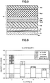
Fig. 3 is a view illustrating a magnetic path by magnetic flux of amain coil 56 to abelt 50 and a heatgeneration assistance plate 69; -
Fig. 4 is a block diagram illustrating control of anIH coil unit 52 according to the first embodiment; -
Fig. 5 is a diagram illustrating the configuration of thebelt 50; -
Fig. 6 is a diagram illustrating a relation of calorific value with respect to thickness of a protective layer and thickness of a heat generation layer; -
Fig. 7 is a diagram illustrating the time of starting of a fixing apparatus or a sleep state; -
Fig. 8 is diagram illustrating operation sequence at the time of the starting of the fixing apparatus or at a recovery time from the sleep state; and -
Fig. 9 is diagram illustrating operation sequence at the time of the starting of a fixing apparatus or at a recovery time from a sleep state according to a modification. - In accordance with an embodiment, a fixing belt has a non-magnetic metal layer and a magnetic metal layer. The thickness of the magnetic metal layer is larger than that the thickness of the non-magnetic metal layer.
- Hereinafter, the fixing belt and a fixing apparatus according to an embodiment are described with reference to the accompanying drawings.
-
Fig. 1 is a side view illustrating animage forming apparatus 10 according to a first embodiment. Hereinafter, anMFP 10 is described as an example of theimage forming apparatus 10. - As shown in
Fig. 1 , the MFP 10 is equipped with ascanner 12, acontrol panel 13 and amain body section 14. Each of thescanner 12, thecontrol panel 13 and themain body section 14 comprises a control section. TheMFP 10 comprises asystem control section 100 serving as a control section for collectively controlling each control section. Thesystem control section 100 includes a CPU (Central Processing Unit) 100a, a ROM (Read Only Memory) 100b and a RAM (Random Access Memory) 100c (refer toFig. 4 ). - The
system control section 100 controls a main body control circuit 101 (refer toFig. 2 ) serving as a control section of themain body section 14. The mainbody control circuit 101 comprises a CPU, a ROM and a RAM (none is shown) . Themain body section 14 is equipped with a paperfeed cassette section 16, aprinter section 18 and afixing apparatus 34. The mainbody control circuit 101 controls the paperfeed cassette section 16, theprinter section 18 and thefixing apparatus 34. - The
scanner 12 reads an image of a document. Thecontrol panel 13 is equipped withinput keys 13a and adisplay section 13b. For example, theinput keys 13a receive an input from a user. For example, thedisplay section 13b is a touch panel type. Thedisplay section 13b receives the input from the user to display information to the user. - The paper
feed cassette section 16 comprises apaper feed cassette 16a and apickup roller 16b. Thepaper feed cassette 16a stores sheets P serving as image receiving media. Thepickup roller 16b picks up the sheet P from thepaper feed cassette 16a. - The
paper feed cassette 16a feeds the sheet P that is not used. A paper feed tray 17 feeds the unused sheet P with apickup roller 17a. - The
printer section 18 forms an image. For example, theprinter section 18 carries out an image forming processing on the image of document read by thescanner 12. Theprinter section 18 is equipped with anintermediate transfer belt 21. Theprinter section 18 supports theintermediate transfer belt 21 through abackup roller 40, a drivenroller 41 and atension roller 42. Thebackup roller 40 is equipped with a driving section (not shown). Theprinter section 18 rotates theintermediate transfer belt 21 in a direction indicated by an arrow m. - The
printer section 18 comprises four sets ofimage forming stations image forming stations image forming stations intermediate transfer belt 21 below theintermediate transfer belt 21. - The
printer section 18 is equipped withcartridges image forming stations cartridges - Hereinafter, the
image forming station 22Y for forming the Y (yellow) image among theimage forming stations image forming stations image forming station 22Y, the detailed description thereof is omitted. - The
image forming station 22Y comprises acharger 26, anexposure scanning head 27, a developingdevice 28 and aphotoconductive cleaner 29. Thecharger 26, theexposure scanning head 27, the developingdevice 28 and thephotoconductive cleaner 29 are arranged around aphotoconductive drum 24 rotating in a direction indicated by an arrow n. - The
image forming station 22Y includes aprimary transfer roller 30. Theprimary transfer roller 30 faces thephotoconductive drum 24 across theintermediate transfer belt 21. - The
image forming station 22Y exposes thephotoconductive drum 24 that is charged by thecharger 26 through theexposure scanning head 27. Theimage forming station 22Y forms an electrostatic latent image on thephotoconductive drum 24. The developingdevice 28 develops the electrostatic latent image on thephotoconductive drum 24 using a two-component developing agent including toner and carrier. - The
primary transfer roller 30 primarily transfers the toner image formed on thephotoconductive drum 24 to theintermediate transfer belt 21. Theimage forming stations intermediate transfer belt 21 through theprimary transfer roller 30. The color toner image is formed by overlapping toner images of Y (yellow), M (magenta), C (cyan) and K (black) in sequence. Thephotoconductive cleaner 29 removes the toner left on thephotoconductive drum 24 after the primary transfer. - The
printer section 18 includes asecondary transfer roller 32. Thesecondary transfer roller 32 faces abackup roller 40 across theintermediate transfer belt 21. Thesecondary transfer roller 32 secondarily transfers the color toner image on theintermediate transfer belt 21 collectively to the sheet P. The sheet P is fed by the paperfeed cassette section 16 or a manualpaper feeding tray 17 along aconveyance path 33. - The
printer section 18 is equipped with abelt cleaner 43 facing a drivenroller 41 across theintermediate transfer belt 21. Thebelt cleaner 43 removes the toner left on theintermediate transfer belt 21 after the secondary transfer. - The
printer section 18 is equipped with aregister roller 33a, a fixingapparatus 34 and asheet discharge roller 36 along theconveyance path 33. Theprinter section 18 includes a bifurcatingsection 37 and areversal conveyance section 38 at the downstream side of the fixingapparatus 34. The bifurcatingsection 37 sends the sheet P subjected to a fixing processing to asheet discharge section 20 or thereversal conveyance section 38. In a case of a duplex printing, thereversal conveyance section 38 reverses the sheet P sent from the bifurcatingsection 37 to a direction of theregister roller 33a and conveys it. TheMFP 10 forms a fixed toner image on the sheet P with theprinter section 18 and then discharges it to thesheet discharge section 20. - Further, the
MFP 10 is not limited to the tandem developing system, and the number of the developingdevices 28 is also not limited. Further, theMFP 10 may transfer the toner image from thephotoconductive drum 24 to the sheet P directly. - Hereinafter, the fixing
apparatus 34 is described in detail. -
Fig. 2 is a side view containing an electromagnetic inductionheating coil unit 52 and a control block of a mainbody control circuit 101. Hereinafter, the electromagnetic induction heating coil unit is referred to as an "IH coil unit". - As shown in
Fig. 2 , the fixingapparatus 34 is equipped with a belt 50 (fixing belt), apress roller 51, anIH coil unit 52, a heat generation assistance plate 69 (magnetic material), an insulating member 691 (sheet), ashield 76 and the mainbody control circuit 101. - The fixing
belt 50 is a cylindrical endless belt. On the inner peripheral surface of the fixingbelt 50, a beltinternal mechanism 55 including anip pad 53 and the heatgeneration assistance plate 69 is arranged. In the present embodiment, thebelt 50 contacts with the heatgeneration assistance plate 69. - The fixing
belt 50 is formed by laminating aheat generation layer 50a (conductive layer), a protective layer 50a1, anelastic layer 50d and a releasinglayer 50c in sequence on abase layer 50b (refer toFig. 3 andFig. 5 ) . Further, as long as the fixingbelt 50 includes theheat generation layer 50a and the protective layer 50a1, no limitation is given to the layer constitution. - For example, the
base layer 50b is made from polyimide resin (PI). For example, theheat generation layer 50a is formed by a non-magnetic metal such as copper (Cu) and becomes a main heat generation section in thebelt 50. For example, the protective layer 50a1 is formed by the magnetic metal such as nickel (Ni) . For example, the releasinglayer 50c is made from fluorine resin such as PFA (Tetrafluoroethylene Perfluoro alkyl vinyl ether copolymer resin) . For example, theelastic layer 50d is formed by an elastic body such as silicone rubber. The shape of thebelt 50 is not limited. - In order to achieve a rapid warming up, the
heat generation layer 50a becomes thin and thus the heat capacity of the fixingbelt 50 becomes low. The warming-up is a processing containing a processing of increasing the temperature of thebelt 50 to a temperature at which a fixing processing is executable. The fixingbelt 50 having low heat capacity shortens the time required in warming-up and saves energy consumption. - For example, in order to reduce the heat capacity of the fixing
belt 50, it is assumed that the thickness of the copper layer of theheat generation layer 50a is equal to or smaller than 12µm. For example, the outer peripheral surface of theheat generation layer 50a is coated by the protective layer 50a1. The protective layer 50a1 can suppress the oxidation of theheat generation layer 50a. The protective layer 50a1 improves the mechanical strength of the fixingbelt 50. The thickness of the protective layer 50a1 is described later. - Further, the
heat generation layer 50a may be formed by performing copper plating after performing a surface treatment on thebase layer 50b made from polyimide resin. By performing the surface treatment, the adhesion strength of thebase layer 50b to theheat generation layer 50a is improved. For example, by performing electroless nickel plating as the surface treatment of thebase layer 50b, thebelt 50 improves the mechanical strength of the fixingbelt 50. - Further, the surface of the
base layer 50b may be roughened through sandblast or chemical etching. By roughening the surface of thebase layer 50b, thebelt 50 further mechanically improves the adhesion strength of thebase layer 50b to theheat generation layer 50a. - Further, a metal such as titanium (Ti) may be dispersed into the polyimide resin to form the
base layer 50b. By dispersing the metal into thebase layer 50b, thebelt 50 further improves the adhesion strength of thebase layer 50b to theheat generation layer 50a. - For example, the
heat generation layer 50a may be made from non-magnetic metal such as aluminum (Al), copper (Cu) and silver (Ag) and the like. Theheat generation layer 50a is not limited to non-magnetic pure metal and may be an alloy having non-magnetic properties. Theheat generation layer 50a may be formed by combining two or more kinds of alloys or pure metals having the non-magnetic properties. Alternatively, theheat generation layer 50a may also be formed by overlapping two or more kinds of material selected from alloys or pure metals having the non-magnetic properties in a layered shape. - As shown in
Fig. 2 , theIH coil unit 52 is equipped with amain coil 56 and acore 57. For example, themain coil 56 is formed by winding litz wire bundling a plurality of copper wire coated with heat-resistant polyamide-imide which is an insulating material. A high frequency current is applied to themain coil 56 from aninverter driving circuit 68. Through enabling the high frequency current to flow to themain coil 56, high frequency magnetic field is generated in the vicinity of themain coil 56. - The
core 57 becomes a magnetic path of the magnetic flux generated by themain coil 56. Thecore 57 has parts protruding to thebelt 50 side. The protruding parts are arranged at a central part and ends of thecore 57 along a circumferential direction of thebelt 50. A corecentral protrusion 57b is arranged at the central part of thecore 57 .Core end protrusions 57c are arranged at both ends of thecore 57. - By arranging the core
central protrusion 57b and thecore end protrusions 57c in thecore 57, the magnetic flux generated by themain coil 56 can efficiently head for thebelt 50 side. - With the magnetic flux in the high frequency magnetic field, an eddy current occurs in the
heat generation layer 50a of thebelt 50. Through the eddy current and electrical resistance of theheat generation layer 50a, Joule heat is generated in theheat generation layer 50a. Through the generation of the Joule heat, thebelt 50 is heated. - The heat
generation assistance plate 69 has a surface facing thebelt 50. When viewed from a width direction (hereinafter, referred to as a "belt width direction") of thebelt 50, the heatgeneration assistance plate 69 is formed into an arc shape along the inner peripheral surface of thebelt 50. The heatgeneration assistance plate 69 may be arc shape viewed from the belt width direction. The position of the heatgeneration assistance plate 69 is determined so that the arc-shape surface of the heatgeneration assistance plate 69 faces thebelt 50. The heatgeneration assistance plate 69 faces themain coil 56 across thebelt 50. - For example, the heat
generation assistance plate 69 includes a magnetic material. The heatgeneration assistance plate 69 may be formed by thin member having magnetic properties such as iron (Fe), nickel (Ni) and stainless (SUS) . For example, the stainless having the magnetic properties may be a magnetic SUS material such as SUS 420. The heatgeneration assistance plate 69 may be a sintered body of the magnetic material such as ferrite or be formed by resin in which the magnetic powder is dispersed as long as the heatgeneration assistance plate 69 has the magnetic properties. The heatgeneration assistance plate 69 is not limited to the thin plate member. The heatgeneration assistance plate 69 may also be formed by combining two or more types of different magnetic material. - For example, the heat
generation assistance plate 69 is a magnetic shunt alloy (ferromagnetism body) of which the Curie point is lower than that of theheat generation layer 50a. Through the magnetic flux generated by themain coil 56, magnetic flux is generated between the heatgeneration assistance plate 69 and thebelt 50. Through the generation of the magnetic flux, thebelt 50 is heated. - Two arc-shaped ends (upper end and lower end) of the heat
generation assistance plate 69 are supported by a foundation (not shown) . For example, the heatgeneration assistance plate 69 is pressed towards thebelt 50. A lateral surface of the heatgeneration assistance plate 69 in a radial direction contacts the inner peripheral surface of thebelt 50. - Through the belt
internal mechanism 55, the heatgeneration assistance plate 69 may be close to /away from thebelt 50. For example, the beltinternal mechanism 55 may enable the lateral surface of the heatgeneration assistance plate 69 in the radial direction to separate from the inner peripheral surface of thebelt 50 at the time of warming up the fixingapparatus 34. -
Fig. 3 is a view illustrating the magnetic paths to thebelt 50 and the heatgeneration assistance plate 69 by the magnetic flux of themain coil 56. - As shown in
Fig. 3 , the magnetic flux generated by themain coil 56 forms a firstmagnetic path 81 induced to theheat generation layer 50a of thebelt 50. The firstmagnetic path 81 passes through acore 57 of themain coil 56 and theheat generation layer 50a of thebelt 50. The magnetic flux generated by themain coil 56 forms a secondmagnetic path 82 induced to the heatgeneration assistance plate 69. The secondmagnetic path 82 is formed at a position adjacent to the firstmagnetic path 81 in a radial direction of thebelt 50 . The secondmagnetic path 82 passes through the heatgeneration assistance plate 69 and theheat generation layer 50a. - For example, the surface of the heat
generation assistance plate 69 at thebelt 50 side is arranged to contact with the inner surface of thebelt 50. The heatgeneration assistance plate 69 has arecess 69d recessed towards a shaft side of thebelt 50. Therecess 69d enables a part of the surface of the heatgeneration assistance plate 69 facing thebelt 50 to separate from the inner surface of thebelt 50. Therecess 69d is arranged at a position facing the corecentral protrusion 57b in theIH coil unit 52. For example, in the circumferential direction of thebelt 50, the width of therecess 69d has length corresponding to the width of the corecentral protrusion 57b. Therecess 69d and the corecentral protrusion 57b are arranged to face each other. In this way, the distance from the corecentral protrusion 57b to the heatgeneration assistance plate 69 is longer than that in a case in which there is norecess 69d. As a result, the magnetic flux in the vicinity of the corecentral protrusion 57b is difficult to decay compared with the case where there is norecess 69d. By arranging therecess 69d in the heatgeneration assistance plate 69, theIH coil unit 52 can efficiently form the firstmagnetic path 81 due to the generated magnetic flux. - Incidentally, the recess area may be configured as space without providing filler in a recess of the
recess 69d. Alternatively, anelastic body 69s for holding lubricating oil such as silicone oil may be arranged in therecess 69d. For example, theelastic body 69s is arranged to contact with the inner peripheral surface of thebelt 50. Through the rotation of thebelt 50, the inner peripheral surface of thebelt 50 is coated by the lubricating oil. Through the lubricating oil, frictional resistance of sliding contact between thebelt 50 and the heatgeneration assistance plate 69 is reduced. Through the lubricating oil existing between thebelt 50 and the heatgeneration assistance plate 69, it is possible to reduce the thermal resistance between thebelt 50 and the heatgeneration assistance plate 69. - The heat
generation assistance plate 69 may be magnetic material of which the Curie point is lower than that of theheat generation layer 50a of thebelt 50 as stated above. For example, the heatgeneration assistance plate 69 is formed by a thin metal member made from the magnetic shunt alloy such as iron or nickel alloy the Curie point of which is 220 degrees centigrade-230degrees centigrade. The magnetism of the heatgeneration assistance plate 69 changes from the ferromagnetism to the paramagnetism if the temperature exceeds the Curie point thereof. If the temperature of the heatgeneration assistance plate 69 exceeds the Curie point, the secondmagnetic path 82 is not formed, thereby not assisting the heating of thebelt 50 . Through forming the heatgeneration assistance plate 69 with the magnetic shunt alloy, by taking the Curie point as a boundary, the heatgeneration assistance plate 69 can assist rise of the temperature of thebelt 50 at the time of a low temperature and suppress excessive rise of the temperature of thebelt 50 at the time of a high temperature. - As shown in
Fig. 2 , ashield 76 is arranged at the inner peripheral side of the heatgeneration assistance plate 69 along the inner peripheral surface thereof. For example, theshield 76 has a substantially arc-shape surface viewed from the belt width direction similar to the heatgeneration assistance plate 69. Theshield 76 may be a substantially arc shape viewed from the belt width direction. Two arc-shaped ends of theshield 76 are supported by a foundation (not shown). Theshield 76 may support the heatgeneration assistance plate 69. For example, theshield 76 is formed by a non-magnetic material such as aluminum and copper. Theshield 76 shields the magnetic flux from theIH coil unit 52. Theshield 76 has arecess 76d recessed towards a shaft side of thebelt 50. Therecess 76d enables a part of theshield 76 to separate from the inner surface of thebelt 50. Therecess 76d is arranged at a position facing the corecentral protrusion 57b in theIH coil unit 52 similar to therecess 69d. For example, in the circumferential direction of thebelt 50, the width of therecess 76d corresponds to the width of therecess 69d. Therecess 76d and the corecentral protrusion 57b are arranged to face each other. In this way, the distance from the corecentral protrusion 57b to theshield 76 is longer than that in a case in which there is norecess 76d. By arranging therecess 76d in theshield 76, theIH coil unit 52 can efficiently form the firstmagnetic path 81 due to the generated magnetic flux. - The
shield 76 is arranged apart from the heatgeneration assistance plate 69 by sandwiching aheat insulating layer 69i therebetween. - An insulating
member 691 is arranged in theheat insulating layer 69i except for a range corresponding to therecess 69d of the heatgeneration assistance plate 69. The insulatingmember 691 is described in detail later. - A
heat pipe 69h is arranged corresponding to therecess 69d. Theheat pipe 69h is arranged at the opposite side of thebelt 50 with respect to the heatgeneration assistance plate 69, in other words, in a recess of therecess 76d at the back side of the heatgeneration assistance plate 69 viewed from thebelt 50 side. Theheat pipe 69h increases heat dissipation from the heatgeneration assistance plate 69 and increases the speed of decrease in temperature. - Returning to
Fig. 2 , anip pad 53 is described. At the inner peripheral side of thebelt 50, thenip pad 53 presses the inner peripheral surface of thebelt 50 to thepress roller 51 side. Anip 54 is formed between thebelt 50 and thepress roller 51. Thenip pad 53 has anip forming surface 53a between thebelt 50 and thepress roller 51. When viewed from the belt width direction, thenip forming surface 53a curves to form a convex towards the inner peripheral surface of thebelt 50. When viewed from the belt width direction, thenip forming surface 53a curves along the outer peripheral surface of thepress roller 51. - For example, the
nip pad 53 is formed by elastic material such as silicon rubber and fluorine rubber. Thenip pad 53 may be formed by heat-resistant resin. For example, the heat-resistant resin is PI (polyimide resin), PPS (polyphenylene sulfide resin), PES (polyether sulphone resin), LCP (liquid crystal polymer) and PF (phenol resin) and the like. - For example, a sheet-like friction reducing member is arranged between the
belt 50 and thenip pad 53. For example, the friction reducing member is formed by a sheet member and the releasing layer having excellent sliding properties and good wear resistance. The friction reducing member is fixedly supported by the beltinternal mechanism 55. The friction reducing member slidably contacts the inner peripheral surface of thebelt 50 that is operating. The friction reducing member may be formed by the following sheet member with lubricity. For example, the sheet member may be composed of glass fiber sheet impregnated with fluororesin. - For example, the
press roller 51 is equipped with a silicone sponge and a silicone rubber layer having heat-resistance around a core metal thereof. For example, a releasing layer is arranged on the surface of thepress roller 51. The releasing layer is formed by the fluorine-based resin such as PFA resin. Thepress roller 51 pressurizes thebelt 50 by apressure mechanism 51a. - As a driving source of the
belt 50 and thepress roller 51, onemotor 51b (driving section) is arranged. Themotor 51b is driven by amotor driving circuit 51c controlled by the mainbody control circuit 101. Themotor 51b is connected with thepress roller 51 via a first gear row (not shown) . Themotor 51b is connected with a belt driving member via a second gear row and a one-way clutch (none is shown) . Thepress roller 51 rotates in an arrow q direction through themotor 51b. In a case in which thebelt 50 abuts against thepress roller 51, thebelt 50 is driven by thepress roller 51 to rotate in an arrow u direction. In a case in which thebelt 50 is separated from thepress roller 51, thebelt 50 rotates in an arrow u direction through themotor 51b. Further, thebelt 50 may be separated from thepress roller 51 and have a driving source thereof . For example, teeth engaged with the gear are arranged at the ends of thebelt 50 along a moving direction thereof, and thebelt 50 is driven in response to rotation of the gear to be driven to rotate by a motor (not shown) . - At the inner peripheral side of the
belt 50, acenter thermistor 61 and an edge thermistor 62 (temperature measurement sections) are arranged. Thecenter thermistor 61 and theedge thermistor 62 are used to measure the temperature of thebelt 50. The measurement result of the temperature of thebelt 50 is input to the mainbody control circuit 101. Thecenter thermistor 61 is arranged at the inner side of the belt width direction. Theedge thermistor 62 is arranged in the heating area of theIH coil unit 52 and the sheet non-passing area in the belt width direction. The mainbody control circuit 101 stops the output of the electromagnetic induction heating in a case in which the temperature of thebelt 50 measured by theedge thermistor 62 is equal to or greater than a threshold value. By stopping the output of the electromagnetic induction heating when the temperature of the sheet non-passing area of thebelt 50 excessively rises, the mainbody control circuit 101 prevents the damage of thebelt 50. - Further, in addition to the
center thermistor 61 and theedge thermistor 62, athermistor 64 may be arranged in the heatgeneration assistance plate 69. Thethermistor 64 measures the temperature of the heatgeneration assistance plate 69. The measurement result of the temperature of the heatgeneration assistance plate 69 is input to the mainbody control circuit 101. For example, the mainbody control circuit 101 may enable the heatgeneration assistance plate 69 abut against thebelt 50 if the temperature of the heatgeneration assistance plate 69 measured by thethermistor 64 is equal to or greater than the threshold value. - The main
body control circuit 101 controls anIH control circuit 67 according to the measurement result of the temperature of thebelt 50 by thecenter thermistor 61 and theedge thermistor 62. TheIH control circuit 67 controls the value of the high frequency current output by theinverter driving circuit 68 under the control of the mainbody control circuit 101. The temperature of thebelt 50 is maintained in various control temperature ranges according to the output by theinverter driving circuit 68. TheIH control circuit 67 is equipped with a CPU, a ROM and a RAM (none is shown). - For example, a
thermostat 63 is arranged in the beltinternal mechanism 55. Thethermostat 63 functions as a safety device of the fixingapparatus 34. Thethermostat 63 operates when thebelt 50 generates abnormal heat and the temperature thereof rises to a cut-off threshold value. Through the operation of thethermostat 63, the current to theIH coil unit 52 is cut off. Through cutting off the current to theIH coil unit 52, the abnormal heat generation of the fixingapparatus 34 can be prevented. -
Fig. 4 is a block diagram illustrating the control of theIH coil unit 52 according to the first embodiment as a main body. - As shown in
Fig. 4 , the MFP 10 (refer toFig. 1 ) is equipped with thesystem control section 100, the mainbody control circuit 101, anIH circuit 120 and themotor driving circuit 51c . TheIH circuit 120 is equipped with arectifying circuit 121, theIH control circuit 67, theinverter driving circuit 68 and acurrent measurement circuit 122. - The current is input to the
IH circuit 120 via arelay 112 from an alternating-current power supply 111. TheIH circuit 120 rectifies the input current through the rectifyingcircuit 121 to supply the rectified current to theinverter driving circuit 68. In a case in which thethermostat 63 is cut off, therelay 112 cuts off the current from the alternating-current power supply 111. Theinverter driving circuit 68 is equipped with adriver IC 68b of an IGBT (Insulated Gate Bipolar Transistor)element 68a. TheIH control circuit 67 controls thedriver IC 68b according to the measurement result of the temperature of thebelt 50 by thecenter thermistor 61 and theedge thermistor 62. TheIH control circuit 67 controls thedriver IC 68b to control the output of theICBT element 68a. Thecurrent measurement circuit 122 sends the measurement result of the output of theIGBT element 68a to theIH control circuit 67. TheIH control circuit 67 controls thedriver IC 68b to make the output of theIH coil unit 52 constant based on the measurement result of the output of theICBT element 68a by thecurrent measurement circuit 122. - The main
body control circuit 101 acquires the temperature of thebelt 50 from thecenter thermistor 61 and theedge thermistor 62. In a case in which thebelt 50 contacts the heatgeneration assistance plate 69, the belt temperature is substantially the same as the temperature of the heatgeneration assistance plate 69. Thus, through acquiring the belt temperature, the temperature of the heatgeneration assistance plate 69 may also be indirectly acquired. In the standby state, the mainbody control circuit 101 controls the frequency applied to theIH coil unit 52 based on the belt temperature to enable the IH output to approach to the target value. In a case in which thebelt 50 does not contact the heatgeneration assistance plate 69, the belt temperature is different from the temperature of the heatgeneration assistance plate 69 in some cases. In this case, the mainbody control circuit 101 may acquire the temperature detected by thethermistor 64 as the temperature of the heatgeneration assistance plate 69. - Further, "the standby state" refers to a standby state in which the fixing
apparatus 34 does not execute the fixing operation and is equivalent to a state in which the MFP 10 (refer toFig. 1 ) does not receive the print request. - First, the shortening of the time required from the dormant state to the starting of forming an image of the fixing
apparatus 34 is described. The time required from the dormant state to the starting of forming an image refers to time required for the starting of the fixingapparatus 34 or recovery time from the dormant state (sleep state) . Hereinafter, the time required from the dormant state to the starting of forming an image is referred to as the recovery time. - The fixing
apparatus 34 shortens the recovery time without increasing amount of the energy consumption. For example, the heat capacity of thebelt 50 is reduced to increase temperature rising speed of thebelt 50. If the heat capacity is reduced, thebelt 50 cannot accumulate needed heat quantity. - For example, if the copper layer serving as the
heat generation layer 50a is relatively thin, the heat capacity of thebelt 50 is reduced, and the heating efficiency of thebelt 50 is improved. On the other hand, thebelt 50 is impossible to accumulate the heat quantity required for fixing operation due to reducing the heat capacity in some cases. In this case, fixing failure (low-temperature offset) may occur. The increasing of the temperature rising rate of thebelt 50 and the accumulation of the heat quantity required for fixing operation by the belt become a trade-off. - For example, the fixing apparatus of a comparative embodiment that is capable of lowering the rotational speed of the
belt 50 can lower the rotational speed of thebelt 50 to avoid the occurrence of the above trade-off. The fixing apparatus of the comparative embodiment is difficult to shorten the recovery time. - In contrast, in a case in which the recovery time is required to be shortened, the same measure as described above cannot be taken. In the present embodiment, while ensuring the heat capacity necessary for the
belt 50, the above-mentioned trade-off is overcome to improve the heating efficiency. - First, with reference to
Fig. 5 , the configuration of thebelt 50 of the present embodiment is described.Fig. 5 is a diagram illustrating the configuration of thebelt 50. Thebelt 50 is formed by sequentially stacking theheat generation layer 50a, the protective layer 50a1, theelastic layer 50d and the releasinglayer 50c on thebase layer 50b. An adhesive layer 50a2 made of nickel may be arranged between thebase layer 50b and theheat generation layer 50a. In the present embodiment, the protective layer 50a1 functions to assist heat generation in addition to the calorific value of theheat generation layer 50a. Incidentally, in addition to the above function, the protective layer 50a1 has a protection function to protect thebelt 50 by preventing oxidation of the surface of theheat generation layer 50a and a durability improvement function to improve the durability of thebelt 50. - For comparison, a belt of the comparative embodiment is described. The protective layer of the belt of the comparative embodiment has a protection function to protect the belt by preventing oxidation of the surface of the
heat generation layer 50a and a durability improvement function to improve the durability of thebelt 50. The thickness of the protective layer of the belt of the comparative embodiment is determined so as to make the protection function and the durability improvement function effective. - In contrast, in the
belt 50 of the present embodiment, the thickness of the protective layer 50a1 is determined so as to satisfy the following conditions. The thickness of the protective layer 50a1 is determined so as to make a heat generation holding function for assisting heat generation by theheat generation layer 50a, the protection function and the durability improvement function effective. - Next, the relation among the
belt 50, the heatgeneration assistance plate 69 and theshield 76 is described. - The
belt 50 and the heatgeneration assistance plate 69 are arranged to contact with each other or be away from each other by a distance at which they can heat each other. - The heat
generation assistance plate 69 and theshield 76 are arranged by sandwiching theheat insulating layer 69i. Theheat insulating layer 69i is constituted so as to make the thermal resistance between the heatgeneration assistance plate 69 and theshield 76 relatively high. For example, theheat insulating layer 69i may be an air layer formed by arranging the heatgeneration assistance plate 69 and theshield 76 at a predetermined distance. Alternatively, theheat insulating layer 69i is constituted so as to make the electrical resistance between the heatgeneration assistance plate 69 and theshield 76 relatively high. For example, theheat insulating layer 69i insulates the space between the heatgeneration assistance plate 69 and theshield 76. For example, air or other insulatingmembers 691 may be filled between the heatgeneration assistance plate 69 and theshield 76. The insulatingmember 691 may, for example, sheet material containing polyimide (Kapton® Technology, etc.) or aramid (Nomex® Technology, etc.) as the material. The insulatingmember 691 may be formed as a film or a sheet in which fiber is woven. It is desired the thickness of the insulatingmember 691 in that case is from 0.1 mm to 0.5 mm. - Between the heat
generation assistance plate 69 and theshield 76, theheat insulating layer 69i which is formed by including the insulatingmember 691 is arranged. In this way, the apparent heat capacity of thebelt 50 becomes small, and the heating efficiency of thebelt 50 is improved. For example, theMFP 10 that is placed in the dormant state at night and the like lowers the temperature of thebelt 50 and the heatgeneration assistance plate 69 to a relatively low temperature. Theheat insulating layer 69i is arranged and the heating efficiency described above is improved, and thus, initial heating shortage of the heatgeneration assistance plate 69 after the dormant state of theMFP 10 is released is compensated, which contributes to the shortening of the rise time from the dormant state the like. - At the time of continuously passing the paper, the heat
generation assistance plate 69, theheat insulating layer 69i and theshield 76 are warmed to a relatively high temperature. Thebelt 50 receives the heat and the viscosity of lubricant (silicon oil) coating the inner surface of thebelt 50 decreases. Through decreasing of the viscosity of the lubricant, the thermal resistance between thebelt 50 and the heatgeneration assistance plate 69 is lowered, and thermal conductivity between thebelt 50 and the heatgeneration assistance plate 69 is increased. In addition, if the thickness of the insulatingmember 691 is from 0.1 mm to 0.5 mm, the heat of the heatgeneration assistance plate 69 and theshield 76 can be used to stabilize the temperature of thebelt 50. In the above case, the apparent heat capacity of thebelt 50 is increased, and the heat of thebelt 50, the heatgeneration assistance plate 69 and theshield 76 can be effectively used, thereby achieving the effect of reducing the power consumption. Further, the printing speed can be accelerated in the foregoing state. - If the thickness of the
heat insulating layer 69i or the insulatingmember 691 is equal to or greater than 0.5mm, the thermal resistance among the heatgeneration assistance plate 69, theheat insulating layer 69i and theshield 76 is increased, and the heat conduction is extremely bad. As a result, although the apparent heat capacity of thebelt 50 is reduced and the rise time from the dormant state is shortened, the thickness of theheat insulating layer 69i or the insulatingmember 691 is not suitable for accelerating the print speed. -
Fig. 6 is a diagram illustrating a relation of the calorific value with respect to the thickness of the protective layer and the thickness of the heat generation layer. InFig. 6 , a case in which the nickel is applied to the material of the protective layer 50a1 and the copper is applied to the material of theheat generation layer 50a is exemplified. Further, inFig. 6 , a case in which the magnetic shunt alloy is applied to the material of the heatgeneration assistance plate 69 and the aluminum is applied to the material of theshield 76 is shown.Fig. 6 shows results generated by analyzing the calorific value of thewhole belt 50 through electromagnetic field analysis in a case of fixing the thickness of the nickel layer of thebelt 50 to 8µm and changing the thickness of the copper layer. The analysis results shown inFig. 6 are generated in a case of respectively setting the thickness of the copper layer to 2µm, 6µm, 12µm and 16µm. - The calorific value of the nickel layer increases as the thickness of the copper layer becomes thinner. The calorific value of the nickel layer and the copper layer and the calorific value of the
whole belt 50 increase as the thickness of the copper layer becomes thinner. - However, if the thickness of the copper layer is too thin and exceeds a certain range, shielding effect of the magnetic flux by the copper layer is reduced and the magnetic flux reaching the heat generation assistance plate 69 (magnetic shunt alloy) is increased. In this way, the heat generation assistance plate 69 (magnetic shunt alloy) arranged at the inside of the
belt 50 is easily heated. In this case, the temperature of the magnetic shunt alloy is raised, the magnetic properties of the magnetic shunt alloy are lost, and the calorific value by the magnetic flux is reduced. For example, if the thickness of the copper layer is equal to or lower than 8µm, the heating efficiency of thebelt 50 is poor and the temperature rise speed thereof is slow. In the foregoing case, it is desired that the thickness of the copper layer is at least 5µm or more so that the temperature of the generation assistance plate 69 (magnetic shunt alloy) is prevented from exceeding the Curie temperature. - If the thickness of the nickel layer becomes thin, the durability of the
belt 50 decreases. In order to maintain the durability of thebelt 50, the thickness of the nickel layer is required to be 6µm or more. In contrast, the thicker the thickness of the nickel layer becomes, the larger the heat capacity by the protective layer 50a1 becomes, and the slower the temperature rise of thebelt 50 becomes. Consequently, the thickness of the nickel layer is required to be thinner than a predetermined thickness. For example, the predetermined thickness is set to 12µm, and the thickness of the nickel layer is equal to or smaller 12µm serving as predetermined thickness. - According to the results of the above study, in the
belt 50 of the present embodiment, the thickness of the copper layer is determined as 6µm, and the thickness of the nickel layer is determined as 10µm, and then the effect of thebelt 50 is evaluated. By mounting thebelt 50 to theMFP 10, it is confirmed that satisfactorily print reaching a print speed of 85 sheets in 1 minute can be realized. The belt of the comparative embodiment is obtained by setting the thickness of the copper layer to 10µm and the thickness of the nickel layer to 8µm. TheMFP 10 is possible to increase the print speed by using the above thebelt 50 compared with a case of using the belt of the comparative embodiment. Thus, thebelt 50 can increase the independent temperature rise properties. - Further, through enabling the fixing
apparatus 34 to execute the following operations, the time required for the starting of the fixingapparatus 34 is shortened to be substantially equal to the temperature rising time of thebelt 50 in a case of heating thebelt 50 independently. -
Fig. 7 is a diagram illustrating the time of the starting of a fixing apparatus or a sleep state. - At the time the fixing
apparatus 34 is in a non-energized state (power off) or in a dormant state (sleep state), thepress roller 51 is maintained in a state separated from thebelt 50. Further, the heatgeneration assistance plate 69 is maintained in a state separated from thebelt 50. Through the above, at the time the fixingapparatus 34 is in the non-energized state (power off) or in the dormant state. If thebelt 50 serving an object to be heated is in a non-contact state with thegeneration assistance plate 69, the heat quantity generated by thebelt 50 itself is used to heat only the heat capacity of thebelt 50. In other words, the heat quantity generated by the heating of thebelt 50 is not conducted to other objects and thebelt 50 is rapidly heated. - Further, the heat
generation assistance plate 69 is maintained in a state separated from thebelt 50. In the heatgeneration assistance plate 69, the eddy current is generated by the magnetic flux penetrating thebelt 50. The temperature of the heatgeneration assistance plate 69 is gradually increased through the self-heating by the eddy current. - With reference to
Fig. 8 , operations at the time of the starting of the fixing apparatus or at the recovery time from the sleep state are described.Fig. 8 is diagram illustrating operation sequence at the time of the starting of the fixing apparatus or at a recovery time from the sleep state. - The
system control section 100 detects an operation (referred to as a start-up operation) for instructing the starting (power on) or the recovery from the sleep state. The mainbody control circuit 101 starts (IH- > ON) heating by the IH coil unit 52 (ACT 11). - Next, the main
body control circuit 101 acquires the temperature detected by thecenter thermistor 61 and theedge thermistor 62 after starting the heating operation (ACT 12A) . The mainbody control circuit 101 integrates the electric power required to enable theIH coil unit 52 to operate and heat thebelt 50. The mainbody control circuit 101 acquires the integrated value as integrated power (ACT 12B). - Next, the main
body control circuit 101 determines whether or not the temperature of thebelt 50 reaches a predetermined temperature (A) after starting the heating operation (ACT 13) . For example, the predetermined temperature (A) is a lower limit temperature of a temperature range to which the temperature of thebelt 50 is independently increased until the press roller (PR) 51 is enabled to contact with thebelt 50. - Next, if it is determined that the temperature of the
belt 50 reaches the predetermined temperature (A) (Yes in ACT 13), the mainbody control circuit 101 enables the press roller (PR) 51 to contact with the belt 50 (ACT 14). - If the temperature of the
belt 50 does not reach the predetermined temperature (A) (No in ACT 13), alternatively, after the processing inACT 14 is terminated, the mainbody control circuit 101 proceeds to the processing in ACT 15. The mainbody control circuit 101 determines whether or not the integrated value (integrated power) of the electric power consumed by heating thebelt 50 exceeds a predetermined value (W) (ACT 15). If it is determined that the integrated power exceeds the predetermined value (W) (Yes in ACT 15), the mainbody control circuit 101 enables the heatgeneration assistance plate 69 to contact with the belt 50 (ACT 16). - If the integrated power does not exceed the predetermined value (W) (No in ACT 15), alternatively, after the processing in
ACT 16 is terminated, the mainbody control circuit 101 proceeds the processing inACT 17. The mainbody control circuit 101 determines whether or not the temperature of thebelt 50 reaches a Ready temperature (B) (ACT 17) . The Ready temperature (B) refers to a representative temperature of a temperature range at which the heating of the temperature of thebelt 50 may be interrupted. For example, the Ready temperature (B) is set to a temperature higher than the predetermined temperature (A). If it is determined that the temperature of thebelt 50 does not reach the Ready temperature (B) (No in ACT 17), the mainbody control circuit 101 repeats the processing subsequent to ACT 12A in the same way as stated above. If it is determined that the temperature of thebelt 50 reaches the Ready temperature (B) (Yes in ACT 17), the mainbody control circuit 101 stops (IH- > ON) the heating by the IH coil unit 52 (ACT 18) . After terminating a series of the processing relating to the start-up operation, the mainbody control circuit 101 enables the fixingapparatus 34 to be a standby state. Further, in the processing inACT 18 described above, the mainbody control circuit 101 stops the heating by theIH coil unit 52; however, the following operation may be executed instead of that. For example, the mainbody control circuit 101 may reduce the current flowing to theIH coil unit 52 to reduce the calorific value of thebelt 50. - According to the foregoing processing, the main
body control circuit 101 presumes the temperature of each section before the heatgeneration assistance plate 69 is enabled to contact with thebelt 50 by taking the integrated value of the electric power required for the heating of thebelt 50 as a reference. The mainbody control circuit 101 enables the heatgeneration assistance plate 69 to contact with thebelt 50 after determining that the temperature of each section is in a desired temperature range. In this way, the mainbody control circuit 101 can manage the time required to increase the temperature of thebelt 50. The mainbody control circuit 101 enables the heatgeneration assistance plate 69 to contact with thebelt 50 after presuming that the temperature of each section is in a desired temperature range. In this way, the mainbody control circuit 101 can shorten the time required until the fixingapparatus 34 is recovered to a state in which an image can be formed by taking the integrated value of the electric power required for the heating of thebelt 50 as a reference. - A modification of the embodiment is described. The main
body control circuit 101 according to the embodiment presumes the temperature of each section before the heatgeneration assistance plate 69 is enabled to contact with thebelt 50 by taking the integrated value of the electric power required for the heating of thebelt 50 as a reference. Instead, the mainbody control circuit 101 according to the modification presumes the temperature of each section before the heatgeneration assistance plate 69 is enabled to contact with thebelt 50 by taking the temperature of the heatgeneration assistance plate 69 as a reference. - As shown in
Fig. 2 to Fig. 4 , the heatgeneration assistance plate 69 is equipped with thethermistor 64 for detecting the temperature of the heatgeneration assistance plate 69 . The mainbody control circuit 101 collects information of the temperature of the heatgeneration assistance plate 69 detected by thethermistor 64. -
Fig. 9 is diagram illustrating operation sequence at the time of the starting of a fixing apparatus or at a recovery time from a sleep state. The description thereof is executed by centering on points different fromFig. 8 . - The
system control section 100 detects an operation (referred to as a start-up operation) for instructing the starting (power on) or the recovery from the sleep state. The mainbody control circuit 101 starts (IH- > ON) heating by the IH coil unit 52 (ACT 11). - Next, the main
body control circuit 101 acquires the temperature detected by thecenter thermistor 61 and theedge thermistor 62 after starting the heating operation (ACT 12A) . The mainbody control circuit 101 determines whether or not the temperature of thebelt 50 reaches the predetermined temperature (A) (ACT 13). If it is determined that the temperature of thebelt 50 reaches the predetermined temperature (A) (Yes in ACT 13), the mainbody control circuit 101 enables the press roller (PR) 51 to contact with the belt 50 (ACT 14). - If it is determined that the temperature of the
belt 50 does not reach the predetermined temperature (A) (No in ACT 13), alternatively, after the processing inACT 14 is terminated, the mainbody control circuit 101 proceeds to the processing in ACT 15A. The mainbody control circuit 101 acquires the temperature of the heatgeneration assistance plate 69 detected by the thermistor 64 (ACT 15A) . The mainbody control circuit 101 determines whether or not the temperature of the heatgeneration assistance plate 69 exceeds a predetermined temperature (C) (ACT 15B). If it is determined that the temperature of the heatgeneration assistance plate 69 exceeds the predetermined temperature (C) (Yes in ACT 15B), the mainbody control circuit 101 enables the heatgeneration assistance plate 69 to contact with the belt 50 (ACT 16). - If it is determined that the temperature of the heat
generation assistance plate 69 does not exceed the predetermined temperature (C) (No in ACT 15B), alternatively, the processing inACT 16 is terminated, the mainbody control circuit 101 proceeds to the processing inACT 17 . The procedures after the processing inACT 17 are the same asFig. 8 . - According to the foregoing processing, the main
body control circuit 101 determines whether the temperature of each section is in a desired temperature range before the heatgeneration assistance plate 69 is enabled to contact with thebelt 50 by taking the temperature of the heatgeneration assistance plate 69 as a reference. The mainbody control circuit 101 enables the heatgeneration assistance plate 69 to contact with thebelt 50 after determining that the temperature of each section is in a desired temperature range. In this way, the mainbody control circuit 101 can manage the time required to increase the temperature of thebelt 50 . The mainbody control circuit 101 enables the heatgeneration assistance plate 69 to contact with thebelt 50 after presuming that the temperature of each section is in a desired temperature range. - Thus, according to the present modification, the same effect as the foregoing embodiment can be achieved. Further, according to the present modification, the main
body control circuit 101 can shorten the time required until the fixingapparatus 34 is recovered to a state in which an image can be formed by taking the temperature of the heatgeneration assistance plate 69 as a reference. - As stated above, the
belt 50 of the embodiment has at least the non-magnetic metal layer and a magnetic metal layer. The thickness of the magnetic metal layer is thicker than that of the non-magnetic metal layer. For example, the thickness of the non-magnetic metal layer may be a range from 5µm to 7µm. The non-magnetic metal layer may be made of copper. Theheat generation layer 50a is an example of the non-magnetic metal layer. The thickness of the magnetic metal layer may be a range from 6µm to 12µm. The magnetic metal layer may be made of nickel. The protective layer 50a1 is an example of the magnetic metal layer. - In one embodiment, the thickness of the magnetic metal layer is at least 10% thicker than the thickness of the non-magnetic metal layer. In another embodiment, the thickness of the magnetic metal layer is at least 25% thicker than the thickness of the non-magnetic metal layer. In yet another embodiment, the thickness of the magnetic metal layer is at least 50% thicker than the thickness of the non-magnetic metal layer.
- The fixing
apparatus 34 of the embodiment has thebelt 50. Furthermore, the fixingapparatus 34 may have a magnetic material the Curie temperature of which is from 200 degrees centigrade to 240 degrees centigrade. The magnetic material may have a surface facing the inner peripheral surface of thebelt 50. The heatgeneration assistance plate 69 is an example of the magnetic material. - The
belt 50 is formed into layer shape and is formed by arranging the base layer (thebase layer 50b), the magnetic metal layer and the non-magnetic metal layer in the order in a direction towards the outer peripheral side from the inner peripheral side of thebelt 50. The magnetic material is located on the inner peripheral side with respect to these layers. - In the above embodiment, the
IH coil unit 52 is arranged at the outer peripheral side of thebelt 50 and is an example of heating thebelt 50 from the outer peripheral side. Instead, theIH coil unit 52 may be arranged at the inner peripheral side of thebelt 50 to heat thebelt 50 from the inner peripheral side. In this case, theIH coil unit 52 may heat a part where thebelt 50 contacts with thepress roller 51 from the inner peripheral side. - With respect to any figure or numerical range for a given characteristic, a figure or a parameter from one range may be combined with another figure or a parameter from a different range for the same characteristic to generate a numerical range.
- Other than in the operating examples, or where otherwise indicated, all numbers, values and/or expressions referring to parameters, measurements, conditions, etc., used in the specification and claims are to be understood as modified in all instances by the term "about."
- While certain embodiments have been described these embodiments have been presented by way of example only, and are not intended to limit the scope of the inventions. Indeed, the novel embodiments described herein may be embodied in a variety of other forms: furthermore various omissions, substitutions and changes in the form of the embodiments described herein may be made without departing from the spirit of the inventions. The accompanying claims and there equivalents are intended to cover such forms or modifications as would fall within the scope and spirit of the invention.
Claims (15)
- A fixing belt for an image forming apparatus, comprising:a non-magnetic metal layer; anda magnetic metal layer, whereina thickness of the magnetic metal layer is larger than a thickness of the non-magnetic metal layer.
- The fixing belt according to claim 1, wherein
the thickness of the non-magnetic metal layer is in a range from 5µm to 7µm. - The fixing belt according to claim 1 or 2, wherein
the thickness of the magnetic metal layer is in a range from 6µm to 12µm. - The fixing belt according to any of claims 1 to 3, further comprising a base layer,
wherein the base layer, the magnetic metal layer, and the non-magnetic metal layer are arranged in order from an inner peripheral side towards an outer peripheral side of the fixing belt. - The fixing belt according to any of claims 1 to 4, wherein
an inner peripheral surface of the fixing belt contacts the magnetic material. - The fixing belt according to any of claims 1 to 5, wherein the thickness of the magnetic metal layer is at least 10% thicker than the thickness of the non-magnetic metal layer.
- An image forming apparatus comprising the fixing belt according to any of claims 1 to 6.
- A fixing apparatus, comprising:a fixing belt comprising a non-magnetic metal layer and a magnetic metal layer, whereina thickness of the magnetic metal layer is larger than a thickness of the non-magnetic metal layer.
- The fixing apparatus according to claim 8, further comprising
a magnetic material configured to generate heat by receiving magnetic flux and supply the heat to the fixing belt;
a shield arranged along the magnetic material to shield the magnetic flux; and
a sheet arranged between the shield and the magnetic material. - The fixing apparatus according to claim 9, wherein
the sheet comprises a polyimide or an aramid. - The fixing apparatus according to any of claims 8 to 10, wherein
the thickness of the non-magnetic metal layer is in a range from 5µm to 7µm. - The fixing apparatus according to any of claim 8 to 11, wherein
the thickness of the magnetic metal layer is in a range from 6µm to 12µm. - The fixing apparatus according to claim 9, wherein
a Curie temperature of the magnetic material is from 200 degrees centigrade to 240 degrees centigrade; and
the magnetic material has a surface facing the inner peripheral surface of the fixing belt. - The fixing apparatus according to any of claims 8 to 13, wherein
the thickness of the magnetic metal layer is at least 10% thicker than the thickness of the non-magnetic metal layer. - An image forming apparatus comprising the fixing apparatus according to any of claims 8 to 14.
Applications Claiming Priority (1)
| Application Number | Priority Date | Filing Date | Title |
|---|---|---|---|
| US15/255,296 US20180067429A1 (en) | 2016-09-02 | 2016-09-02 | Fixing belt and fixing apparatus |
Publications (1)
| Publication Number | Publication Date |
|---|---|
| EP3291021A1 true EP3291021A1 (en) | 2018-03-07 |
Family
ID=59409250
Family Applications (1)
| Application Number | Title | Priority Date | Filing Date |
|---|---|---|---|
| EP17183252.0A Withdrawn EP3291021A1 (en) | 2016-09-02 | 2017-07-26 | Fixing belt and fixing apparatus |
Country Status (3)
| Country | Link |
|---|---|
| US (1) | US20180067429A1 (en) |
| EP (1) | EP3291021A1 (en) |
| CN (1) | CN107797421A (en) |
Families Citing this family (3)
| Publication number | Priority date | Publication date | Assignee | Title |
|---|---|---|---|---|
| JP2019124716A (en) * | 2018-01-11 | 2019-07-25 | 株式会社東芝 | Image forming device and image forming method |
| JP2020043133A (en) * | 2018-09-06 | 2020-03-19 | キオクシア株式会社 | Magnetic storage device |
| JP7476515B2 (en) * | 2019-11-01 | 2024-05-01 | 富士フイルムビジネスイノベーション株式会社 | Fixing belt, fixing device, and image forming apparatus |
Citations (6)
| Publication number | Priority date | Publication date | Assignee | Title |
|---|---|---|---|---|
| US6049691A (en) * | 1996-05-31 | 2000-04-11 | Canon Kabushiki Kaisha | Image heating apparatus |
| US20090317158A1 (en) * | 2008-06-19 | 2009-12-24 | Konica Minolta Business Technologies, Inc. | Fixing device and image formation apparatus |
| JP2010217841A (en) * | 2009-03-19 | 2010-09-30 | Konica Minolta Business Technologies Inc | Fixing device and image forming device |
| US20140241771A1 (en) * | 2013-02-26 | 2014-08-28 | Hiroyuki Endo | Base for fixing belt, fixing belt, fixing device, and image forming apparatus |
| US20140301761A1 (en) * | 2013-04-03 | 2014-10-09 | Synztec Co., Ltd. | Multilayer metal member for image fixation |
| US9316976B1 (en) * | 2015-04-23 | 2016-04-19 | Kabushiki Kaisha Toshiba | Induction fixing device with magnetic member including a mesh part |
-
2016
- 2016-09-02 US US15/255,296 patent/US20180067429A1/en not_active Abandoned
-
2017
- 2017-07-13 CN CN201710571314.0A patent/CN107797421A/en active Pending
- 2017-07-26 EP EP17183252.0A patent/EP3291021A1/en not_active Withdrawn
Patent Citations (6)
| Publication number | Priority date | Publication date | Assignee | Title |
|---|---|---|---|---|
| US6049691A (en) * | 1996-05-31 | 2000-04-11 | Canon Kabushiki Kaisha | Image heating apparatus |
| US20090317158A1 (en) * | 2008-06-19 | 2009-12-24 | Konica Minolta Business Technologies, Inc. | Fixing device and image formation apparatus |
| JP2010217841A (en) * | 2009-03-19 | 2010-09-30 | Konica Minolta Business Technologies Inc | Fixing device and image forming device |
| US20140241771A1 (en) * | 2013-02-26 | 2014-08-28 | Hiroyuki Endo | Base for fixing belt, fixing belt, fixing device, and image forming apparatus |
| US20140301761A1 (en) * | 2013-04-03 | 2014-10-09 | Synztec Co., Ltd. | Multilayer metal member for image fixation |
| US9316976B1 (en) * | 2015-04-23 | 2016-04-19 | Kabushiki Kaisha Toshiba | Induction fixing device with magnetic member including a mesh part |
Also Published As
| Publication number | Publication date |
|---|---|
| CN107797421A (en) | 2018-03-13 |
| US20180067429A1 (en) | 2018-03-08 |
Similar Documents
| Publication | Publication Date | Title |
|---|---|---|
| US8718506B2 (en) | Fixing device and image forming apparatus incorporating same | |
| US9523949B1 (en) | Image forming apparatus that controls an image forming section and a fixing device | |
| CN104714388B (en) | Fixing device and image forming device | |
| US9857743B2 (en) | Fixing device and image forming apparatus having the same | |
| US20180067429A1 (en) | Fixing belt and fixing apparatus | |
| US20160116871A1 (en) | Fixing device and image forming apparatus | |
| US10571836B2 (en) | Fixing apparatus | |
| US9971287B2 (en) | Fixing device comprising a magnetic shunt alloy and image forming apparatus | |
| US10025238B2 (en) | Fixing apparatus that controls current for driving an induction heater | |
| US9268271B1 (en) | Fixing device, image forming apparatus and drive load reduction method of the fixing device | |
| US20160259280A1 (en) | Fixing device and image forming apparatus | |
| US8913938B2 (en) | Fixing device and image formation apparatus | |
| CN106406055B (en) | Fixing device and image forming device | |
| JP6579812B2 (en) | Fixing device | |
| US9389557B1 (en) | Fixing device |
Legal Events
| Date | Code | Title | Description |
|---|---|---|---|
| PUAI | Public reference made under article 153(3) epc to a published international application that has entered the european phase |
Free format text: ORIGINAL CODE: 0009012 |
|
| AK | Designated contracting states |
Kind code of ref document: A1 Designated state(s): AL AT BE BG CH CY CZ DE DK EE ES FI FR GB GR HR HU IE IS IT LI LT LU LV MC MK MT NL NO PL PT RO RS SE SI SK SM TR |
|
| AX | Request for extension of the european patent |
Extension state: BA ME |
|
| STAA | Information on the status of an ep patent application or granted ep patent |
Free format text: STATUS: THE APPLICATION IS DEEMED TO BE WITHDRAWN |
|
| 18D | Application deemed to be withdrawn |
Effective date: 20180908 |