EP3290970A1 - Multicore fiber - Google Patents
Multicore fiber Download PDFInfo
- Publication number
- EP3290970A1 EP3290970A1 EP16786486.7A EP16786486A EP3290970A1 EP 3290970 A1 EP3290970 A1 EP 3290970A1 EP 16786486 A EP16786486 A EP 16786486A EP 3290970 A1 EP3290970 A1 EP 3290970A1
- Authority
- EP
- European Patent Office
- Prior art keywords
- light
- mode
- core
- clad
- multicore fiber
- Prior art date
- Legal status (The legal status is an assumption and is not a legal conclusion. Google has not performed a legal analysis and makes no representation as to the accuracy of the status listed.)
- Withdrawn
Links
Images








Classifications
-
- G—PHYSICS
- G02—OPTICS
- G02B—OPTICAL ELEMENTS, SYSTEMS OR APPARATUS
- G02B6/00—Light guides; Structural details of arrangements comprising light guides and other optical elements, e.g. couplings
- G02B6/02—Optical fibres with cladding with or without a coating
- G02B6/02042—Multicore optical fibres
-
- G—PHYSICS
- G02—OPTICS
- G02B—OPTICAL ELEMENTS, SYSTEMS OR APPARATUS
- G02B6/00—Light guides; Structural details of arrangements comprising light guides and other optical elements, e.g. couplings
- G02B6/02—Optical fibres with cladding with or without a coating
-
- G—PHYSICS
- G02—OPTICS
- G02B—OPTICAL ELEMENTS, SYSTEMS OR APPARATUS
- G02B6/00—Light guides; Structural details of arrangements comprising light guides and other optical elements, e.g. couplings
- G02B6/02—Optical fibres with cladding with or without a coating
- G02B6/02004—Optical fibres with cladding with or without a coating characterised by the core effective area or mode field radius
- G02B6/02009—Large effective area or mode field radius, e.g. to reduce nonlinear effects in single mode fibres
- G02B6/02014—Effective area greater than 60 square microns in the C band, i.e. 1530-1565 nm
-
- G—PHYSICS
- G02—OPTICS
- G02B—OPTICAL ELEMENTS, SYSTEMS OR APPARATUS
- G02B6/00—Light guides; Structural details of arrangements comprising light guides and other optical elements, e.g. couplings
- G02B6/02—Optical fibres with cladding with or without a coating
- G02B6/02004—Optical fibres with cladding with or without a coating characterised by the core effective area or mode field radius
- G02B6/02009—Large effective area or mode field radius, e.g. to reduce nonlinear effects in single mode fibres
- G02B6/02023—Based on higher order modes, i.e. propagating modes other than the LP01 or HE11 fundamental mode
-
- G—PHYSICS
- G02—OPTICS
- G02B—OPTICAL ELEMENTS, SYSTEMS OR APPARATUS
- G02B6/00—Light guides; Structural details of arrangements comprising light guides and other optical elements, e.g. couplings
- G02B6/02—Optical fibres with cladding with or without a coating
- G02B6/036—Optical fibres with cladding with or without a coating core or cladding comprising multiple layers
-
- G—PHYSICS
- G02—OPTICS
- G02B—OPTICAL ELEMENTS, SYSTEMS OR APPARATUS
- G02B6/00—Light guides; Structural details of arrangements comprising light guides and other optical elements, e.g. couplings
- G02B6/02—Optical fibres with cladding with or without a coating
- G02B6/036—Optical fibres with cladding with or without a coating core or cladding comprising multiple layers
- G02B6/03616—Optical fibres characterised both by the number of different refractive index layers around the central core segment, i.e. around the innermost high index core layer, and their relative refractive index difference
- G02B6/03638—Optical fibres characterised both by the number of different refractive index layers around the central core segment, i.e. around the innermost high index core layer, and their relative refractive index difference having 3 layers only
- G02B6/0365—Optical fibres characterised both by the number of different refractive index layers around the central core segment, i.e. around the innermost high index core layer, and their relative refractive index difference having 3 layers only arranged - - +
-
- G—PHYSICS
- G02—OPTICS
- G02B—OPTICAL ELEMENTS, SYSTEMS OR APPARATUS
- G02B6/00—Light guides; Structural details of arrangements comprising light guides and other optical elements, e.g. couplings
- G02B6/02—Optical fibres with cladding with or without a coating
- G02B6/036—Optical fibres with cladding with or without a coating core or cladding comprising multiple layers
- G02B6/03694—Multiple layers differing in properties other than the refractive index, e.g. attenuation, diffusion, stress properties
-
- G—PHYSICS
- G02—OPTICS
- G02B—OPTICAL ELEMENTS, SYSTEMS OR APPARATUS
- G02B6/00—Light guides; Structural details of arrangements comprising light guides and other optical elements, e.g. couplings
- G02B6/44—Mechanical structures for providing tensile strength and external protection for fibres, e.g. optical transmission cables
Definitions
- the present invention relates to a multicore fiber and is suitable for improving a degree of freedom for design.
- an optical fiber used for an optical fiber communication system spreading generally has a structure in which outer circumference of one core is surrounded by a clad and an optical signal is propagated through the core, so that information is transmitted. Recently, an amount of information transmitted increases drastically with the spread of the optical fiber communication system. According to the increase in the amount of information transmitted, in the optical fiber communication system, a large number of optical fibers such as dozens or hundreds of optical fibers are used and large-capacity long-distance optical communication is performed.
- Patent Literature 1 An example of the multicore fiber is described in Patent Literature 1 described below.
- one core is disposed on a center of a clad and six cores are disposed around the core disposed on the center. Because such an arrangement is a structure in which the cores can be disposed in a closest packing state, a large number of cores can be disposed with respect to an outer diameter of a specific clad.
- propagation constants of light propagated through the cores adjacent to each other are different from each other to suppress crosstalk of light propagated through the individual cores.
- the multicore fiber is called a trench type and a configuration from the core to the low refractive index layer is called a core element.
- propagation constants of light propagated through the cores adjacent to each other are preferably different from each other to suppress the crosstalk of light propagated through the individual cores.
- an object of the present invention is to provide a multicore fiber capable of improving a degree of freedom for design.
- the present invention provides a multicore fiber for performing communication using light up to an xth-order LP mode (where x is an integer of 1 or more) in a communication band.
- the multicore fiber includes a plurality of cores; a clad that surrounds the plurality of cores and has a refractive index lower than refractive indexes of the plurality of cores; and a cover layer that covers the clad and has a refractive index higher than the refractive index of the clad.
- each of the plurality of cores propagates light up to an (x + 1)th-order LP mode.
- a core pitch is set to a distance at which crosstalk of the light up to the xth-order LP mode becomes -40 dB/km or less and crosstalk of light of the (x + 1)th-order LP mode becomes -30 dB/km or more.
- a distance between the core disposed on an outermost side in the clad and the cover layer is set to a distance at which an excessive loss of the light up to the xth-order LP mode, propagated through the core disposed on the outermost side, due to absorption into the cover layer becomes 0.001 dB/km or less and an excessive loss of the light of the (x + 1)th-order LP mode, propagated through the core disposed on the outermost side, due to absorption into the cover layer becomes 3 dB/km or more.
- each core is a core propagating light of a higher-order mode by a 1 LP mode as compared with cores propagating only the light up to the xth-order LP mode
- confinement of the light up to the xth-order LP mode in the core can be intensified. Therefore, as compared with a multicore fiber configured using the cores propagating only the light up to the xth-order LP mode, crosstalk of the light up to the xth-order mode can be suppressed.
- a degree of freedom for designing a core interval and a degree of freedom for designing a refractive index or a diameter of each core are further improved as compared with the multicore fiber configured using the cores propagating the light up to the xth-order LP mode.
- the light of the (x + 1)th-order LP mode that is propagated through the core located at the outermost side in the clad and is unnecessary for communication is absorbed into the cover layer and is lost.
- the core pitch is set to the distance at which the crosstalk of the light up to the xth-order LP mode becomes -40 dB/km or less and the crosstalk of the light of the (x + 1)th-order LP mode becomes -30 dB/km or more.
- the crosstalk of the light up to the xth-order LP mode used for the communication is suppressed and the crosstalk of the light of the (x + 1)th-order LP mode to be light unnecessary for the communication occurs.
- the light of the (x + 1)th-order mode can be moved to the core located at the outermost side in the clad by the crosstalk and is absorbed into the cover layer as described above.
- the crosstalk between the modes used for signal transmission can be improved by intensifying the confinement of the light up to the xth-order mode while propagation of the light of the (x + 1)th-order mode unnecessary for the signal transmission is suppressed and a degree of freedom for designing the core interval and a degree of freedom for designing a refractive index or a diameter of the core can be improved.
- the multicore fiber further includes an extension portion that extends such that diameters of the plurality of cores decrease, in a part of the plurality of cores in a longitudinal direction, and in the extension portion, the plurality of cores propagate the light up to the xth-order LP mode and propagation of the light of the (x + 1)th-order LP mode is preferably suppressed.
- a loss of the light of the (x + 1)th-order LP mode is more preferably 20 dB or more.
- the extension portion is provided, so that the light of the (x + 1)th-order LP mode unnecessary for the signal transmission can be caused to be further lost, and light of a mode unnecessary for communication can be eliminated more appropriately.
- x may be 1.
- a multicore fiber capable of improving a degree of freedom for design is provided.
- FIG. 1 is a diagram illustrating an aspect of a multicore fiber according to this embodiment.
- a multicore fiber 1 includes a plurality of core elements 10, a clad 20 that surrounds the individual core elements 10 without clearance, and a cover layer 30 that covers the clad 20.
- One core element 10 is disposed as a core element of a first layer at a center of the clad 20.
- the plurality of core elements 10 are disposed as core elements of a second layer at an outer circumferential side of the core element 10 of the first layer, the plurality of core elements 10 are disposed as core elements of a third layer at outer circumferential sides of the core elements 10 of the second layer, and the plurality of core elements 10 are disposed as core elements of a fourth layer at outer circumferential sides of the core elements 10 of the third layer.
- the core elements are disposed by 1, 6, 12, and 12 in the four layers.
- a triangular lattice can be drawn by a line connecting centers of the core elements 10 adjacent to each other and each core element 10 is disposed on each lattice point of the triangular lattice. In this way, the plurality of core elements 10 are disposed in a closest packing state.
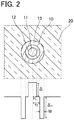
- FIG. 2 is a diagram illustrating a refractive index profile of the individual core elements 10 of the multicore fiber 1 illustrated in FIG. 1 .
- a refractive index of the core 11 of the core element 10 is higher than a refractive index of the inner clad 12 and a refractive index of the low refractive index layer 13 is lower than the refractive index of the inner clad 12 and a refractive index of the clad 20.
- each low refractive index layer 13 has a groove shape and each core element 10 has a trench structure. By the trench structure, confinement of light propagated through each core 11 of the multicore fiber 1 can be intensified.
- the refractive index of the inner clad 12 is the same refractive index as the refractive index of the clad 20.
- each core element 10 of the multicore fiber 1 has the refractive index described above
- the clad 20 and each inner clad 12 are made of quartz to which dopant is not added
- each first core 11 is made of quartz to which dopant such as germanium to increase a refractive index is added
- the low refractive index layer 13 is made of quartz to which dopant such as fluorine to decrease a refractive index is added.
- each core element 10 propagates light of an LP01 mode and light of an LP11 mode.
- an effective area A eff at a wavelength of 1550 nm is preferably almost equal to 80 ⁇ m 2 , from a viewpoint of connectivity with a standard single mode fiber.
- the effective area A eff of the light of the LP11 mode propagated through the core 11 at the wavelength of 1550 nm is roughly 92 ⁇ m 2 .
- the refractive index of the cover layer 30 is higher than the refractive index of the clad 20.
- the cover layer 30 has a property of absorbing light and light reaching the cover layer 30 from the clad 20 is absorbed into the cover layer 30 and disappears.
- an ultraviolet curing resin can be used as an example of a material configuring the cover layer 30, an ultraviolet curing resin can be used.
- a clad thickness Tc means a distance from a center of the core 11 disposed on the outermost circumference to an outer circumferential surface of the clad 20.
- the clad thickness Tc is constant.
- FIG. 3 is a diagram illustrating a calculation result of a relation of the clad thickness Tc and an excessive loss of light due to absorption into the cover layer 30, in the case in which the relative refractive index difference ⁇ of the core 11 to the clad 20 is 0.45% and the radius r 1 of the core 11 is 5.17 ⁇ m, in Table 1.
- the relative refractive index difference ⁇ of the core 11 to the clad 20 is 0.45% and the radius r 1 of the core 11 is 5.17 ⁇ m, in Table 1.
- a solid line shows a state in which a ratio W/r 1 of the radius r 1 of the core 11 and a thickness W of the low refractive index layer 13 is 0.8
- a broken line shows a state in which the ratio W/r 1 of the radius r 1 of the core 11 and the thickness W of the low refractive index layer 13 is 0.9
- a dotted line shows a state in which the ratio W/r 1 of the radius r 1 of the core 11 and the thickness W of the low refractive index layer 13 is 1.0.
- a solid line shows a state in which the ratio W/r 1 of the radius r 1 of the core 11 and the thickness W of the low refractive index layer 13 is 0.7
- a broken line shows a state in which the ratio W/r 1 of the radius r 1 of the core 11 and the thickness W of the low refractive index layer 13 is 0.8
- a dotted line shows a state in which the ratio W/r 1 of the radius r 1 of the core 11 and the thickness W of the low refractive index layer 13 is 0.9.
- a solid line shows a state in which the ratio W/r 1 of the radius r 1 of the core 11 and the thickness W of the low refractive index layer 13 is 0.6
- a broken line shows a state in which the ratio W/r 1 of the radius r 1 of the core 11 and the thickness W of the low refractive index layer 13 is 0.7
- a dotted line shows a state in which the ratio W/r 1 of the radius r 1 of the core 11 and the thickness W of the low refractive index layer 13 is 0.8.
- the light of the LP01 mode is light in which a wavelength where an effective area A eff is largest is 1625 nm in a C band and an L band and the light of the LP11 mode is light in which a wavelength where an effective area A eff is smallest is 1530 nm in the C band and the L band.
- an optical fiber is not laid linearly and is bent and laid. Therefore, in the calculations of FIGS. 3 to 5 , a bending radius of the multicore fiber is set to 140 mm.
- an excessive loss of the light of the LP01 mode due to absorption into the cover layer 30 becomes 0.001 dB/km or less in a region where the clad thickness Tc is roughly 31 ⁇ m. If it is considered that a propagation loss of the standard single mode fiber is 0.19 dB/km, a difference of 0.001 dB/km is a very small value. In addition, it is seen that an excessive loss of the light of the LP11 mode due to absorption into the cover layer 30 becomes 3 dB/km or more in a region where the clad thickness Tc is roughly 31 ⁇ m.
- the light is propagated through the multicore fiber 1 by 10 km, so that power can be set to 1/1000 or less. Therefore, propagation of the light of the LP11 mode unnecessary for signal transmission can be suppressed.
- a wavelength of the light of the LP01 mode shows an excessive loss due to absorption into the cover layer 30 at a wavelength where the effective area A eff is largest and a wavelength of the light of the LP11 mode shows an excessive loss due to absorption into the cover layer 30 at a wavelength where the effective area A eff is smallest.
- a distance between each core 11 disposed on the outermost side in the clad 20 and the cover layer 30 is set to a distance at which the excessive loss of the light of the LP01 mode (primary LP mode), propagated through the core 11 disposed on the outermost side, due to absorption into the cover layer 30, becomes 0.001 dB/km or less and the excessive loss of the light of the LP11 mode (secondary LP mode), propagated through the core 11 disposed on the outermost side, due to absorption into the cover layer 30, becomes 3 dB/km or more.
- the light of the LP01 mode propagated through the core element 10 disposed on the outermost circumference is affected by the excessive loss due to absorption into the cover layer 30 not interfering with the optical communication and power of the light of the LP11 mode propagated through the core element 10 disposed on the outermost circumference is notably decreased by the excessive loss due to absorption into the cover layer 30.
- the core pitch is an inter-center distance of the cores 11 adjacent to each other.
- FIG. 6 is a diagram illustrating a calculation result of a relation of a bending radius of the multicore fiber 1 according to this embodiment and the crosstalk.
- a core pitch ⁇ becomes 32 ⁇ m.
- a core pitch ⁇ is set to 32 ⁇ m
- wavelengths of the light of the LP01 mode and the light of the LP11 mode are set to the wavelengths used in the calculations of FIGS.
- the core pitch ⁇ of the multicore fiber 1 is set to a distance at which the crosstalk of the light of the LP01 mode (primary LP mode) becomes -40 dB/km or less and the crosstalk of the light of the LP11 mode (secondary LP mode) becomes -30 dB/km or more.
- the crosstalk of the light of the LP01 mode propagated through each core element 10 is suppressed.
- the light of the LP11 mode propagated through each core element 10 is moved by the crosstalk. Therefore, the light of the LP11 mode propagated through the first to third layers can be moved to the core element 10 of the fourth layer to be the outermost circumference by the crosstalk.
- each core element 10 is a core element propagating light of a higher-order mode by a 1 mode as compared with the core element propagating the light of only the LP01 mode (primary LP mode)
- confinement of the light of the LP01 mode in the core 11 can be intensified. Therefore, the crosstalk of the light of the LP01 mode can be suppressed as compared with the core propagating only the light of the LP01 mode. For this reason, a degree of freedom for designing the core pitch and a degree of freedom for designing a refractive index or a diameter of each core are improved as compared with the multicore fiber propagating only the light of the LP01 mode.
- the distance between the core 11 disposed on the outermost side and the cover layer, that is, the clad thickness Tc is set to a magnitude at which the excessive loss of the light of the LP01 mode, propagated through the core 11 disposed on the outermost side, due to absorption into the cover layer 30, becomes 0.001 dB/km or less and the excessive loss of the light of the LP11 mode, propagated through the core 11 disposed on the outermost side, due to absorption into the cover layer 30, becomes 3 dB/km or more. Therefore, the light of the LP11 mode that is propagated through the core 11 located at the outermost side in the clad and is unnecessary for communication is absorbed into the cover layer 30 and is lost.
- the core pitch ⁇ is set to a distance at which the crosstalk of the light of the LP01 mode becomes -40 dB/km or less and the crosstalk of the light of the LP11 mode becomes -30 dB/km or more. Therefore, the crosstalk of the light of the LP01 mode used for the communication is suppressed and the crosstalk of the light of the LP11 mode to be light unnecessary for the communication occurs. As a result, the light of the LP11 mode can be moved to the core 11 disposed on the outermost side in the clad 20 by the crosstalk.
- the light of the LP11 mode propagated through the core 11 disposed on the inner circumferential side of the clad 20 is moved to the core 11 disposed on the outermost side of the clad 20 and is absorbed into the cover layer 30. Therefore, according to the multicore fiber 1 according to this embodiment, the crosstalk of the LP01 mode used for signal transmission can be improved while the propagation of the light of the LP11 mode not used for the signal transmission is suppressed.
- FIG. 7 is a cross-sectional view of a multicore fiber according to this embodiment, vertical to a longitudinal direction
- FIG. 8 is a diagram illustrating a refractive index profile of core elements in a multicore fiber 2 of FIG. 7 .
- the multicore fiber 2 according to this embodiment is different from the multicore fiber 1 according to the first embodiment in that each core element 10 does not have an inner clad 12 and a core 11 is surrounded by a low refractive index layer 13 directly.
- each core element 10 propagates light of an LP01 mode and light of an LP11 mode.
- an effective area A eff of the light of the LP01 mode propagated through each core element is preferably larger than 80 ⁇ m 2 , from the same reason as the first embodiment.
- combinations of a relative refractive index difference ⁇ of the core 11 to a clad 20 when an effective area A eff of the light of the LP01 mode to be light of a wavelength of 1550 nm becomes 80 ⁇ m 2 and a radius r 1 of the core 11, in the case in which a relative refractive index difference ⁇ t of the low refractive index layer 13 to the clad 20 is -0.7% are shown in Table 2.
- Table 2 ⁇ [%] 0.4 0.41 0.42 0.43 0.44 0.45 0.46 0.47 0.48 0.49 0.5 r 1 [ ⁇ m] 6.08 6.08 6.09 6.1 6.1 6.11 6.12 6.12 6.13 6.14 6.14
- an effective area A eff of the light of the LP11 mode propagated through the core 11 is roughly 119 ⁇ m 2 .
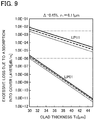
- FIG. 9 is a diagram illustrating a calculation result of a relation of a clad thickness Tc and an excessive loss of light due to absorption into the cover layer 30, in the case in which a relative refractive index difference ⁇ of the core 11 to the clad 20 is 0.45% and a radius of the core 11 is 6.11 ⁇ m.
- FIG. 10 is a diagram illustrating a calculation result of a relation of the clad thickness Tc and the excessive loss of light due to absorption into the cover layer 30, in the case in which the relative refractive index difference ⁇ of the core 11 to the clad 20 is 0.46% and the radius r 1 of the core 11 is 6.12 ⁇ m.
- FIG. 10 is a diagram illustrating a calculation result of a relation of a clad thickness Tc and an excessive loss of light due to absorption into the cover layer 30, in the case in which the relative refractive index difference ⁇ of the core 11 to the clad 20 is 0.46% and the radius r 1 of the core 11 is 6.
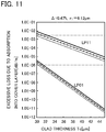
- FIG. 11 is a diagram illustrating a calculation result of a relation of the clad thickness Tc and the excessive loss of light due to absorption into the cover layer 30, in the case in which the relative refractive index difference ⁇ of the core 11 to the clad 20 is 0.47% and the radius r 1 of the core 11 is 6.12 ⁇ m.
- a wavelength of the light of the LP01 mode is set to 1625 nm and a wavelength of the light of the LP11 mode is set to 1530 nm.
- a bending radius of the multicore fiber is set to 140 mm, from the same reason as the first embodiment.
- an excessive loss due to absorption into the cover layer 30 becomes 0.001 dB/km or less in a region where the clad thickness Tc is roughly 31 ⁇ m and in the light of the LP11 mode, an excessive loss due to absorption into the cover layer 30 becomes 3 dB/km or more in a region where the clad thickness Tc is roughly 31 ⁇ m.
- a wavelength of the light of the LP01 mode is a wavelength where the effective area A eff is largest and a wavelength of the light of the LP11 mode is a wavelength where the effective area A eff is smallest.
- a distance between the core 11 disposed on the outermost side in the clad 20 and the cover layer 30 is set to a distance at which the excessive loss of the light of the LP01 mode, propagated through the core 11 disposed on the outermost side, due to absorption into the cover layer 30, becomes 0.001 dB/km or less and the excessive loss of the light of the LP11 mode, propagated through the core 11 disposed on the outermost side, due to absorption into the cover layer 30, becomes 3 dB/km or more.
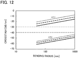
- FIG. 12 is a diagram illustrating a calculation result of a relation of a bending radius of the multicore fiber 2 according to this embodiment and the crosstalk.
- a core pitch ⁇ is set to 32 ⁇ m and a wavelength of the light of the LP01 mode and a wavelength of the light of the LP11 mode are set to the wavelengths used in the calculations of FIGS. 9 to 11 .
- a solid line shows a result in which a relative refractive index difference ⁇ of the core 11 to the clad 20 and the radius of the core 11, used in the calculation of FIG.
- a ratio W/r 1 of a radius r 1 of the core 11 and a thickness W of the low refractive index layer 13 is calculated as 0.9.
- a broken line shows a result in which the relative refractive index difference ⁇ of the core 11 to the clad 20 and the radius of the core 11, used in the calculation of FIG. 10 , are used and the ratio W/r 1 of the radius r 1 of the core 11 and the thickness W of the low refractive index layer 13 is calculated as 0.8.
- a dotted line shows a result in which the relative refractive index difference ⁇ of the core 11 to the clad 20 and the radius of the core 11, used in the calculation of FIG. 11 , are used and the ratio W/r 1 of the radius r 1 of the core 11 and the thickness W of the low refractive index layer 13 is calculated as 0.7.
- the wavelength of the light of the LP01 mode is calculated as a wavelength where an effective area A eff is largest and the wavelength of the light of the LP11 mode is calculated as a wavelength where the effective area A eff is smallest. Therefore, similarly to the first embodiment, even in this embodiment, there is the core pitch ⁇ where the crosstalk of the light of the LP01 mode can be set to a small value not interfering with the optical communication and the crosstalk of the light of the LP11 mode can be set to a large value, when the light of the LP01 mode and the light of the LP11 mode are propagated in the same wavelength band.
- the core pitch ⁇ of the multicore fiber 2 is set to a distance at which the crosstalk of the light of the LP01 mode (primary LP mode) becomes -40 dB/km or less and the crosstalk of the light of the LP11 mode (secondary LP mode) becomes -30 dB/km or more.
- the crosstalk of the LP01 mode can be improved while the propagation of the light of the LP11 mode is suppressed.
- FIGS. 13 to 15 Components equal to or equivalent to those in the first embodiment are denoted with the same reference numerals and overlapped description is omitted except for the case in which description is given particularly.
- FIG. 13 is a diagram illustrating an aspect of a multicore fiber according to this embodiment.
- each core element 10 has the same configuration as the configuration of the core element 10 in the multicore fiber 1 according to the first embodiment. Therefore, even in this embodiment, each core element 10 is configured to propagate light of an LP01 mode and light of an LP11 mode.
- a line connecting individual cores 11 becomes a triangular lattice.
- a line connecting the individual cores 11 becomes a square lattice.
- a distance between each of the four cores 11 disposed on an outermost side in the clad 20 and a cover layer 30 is set to a distance at which an excessive loss of the light of the LP01 mode (primary LP mode), propagated through the cores 11 disposed on the outermost side, due to absorption into the cover layer 30, becomes 0.001 dB/km or less and an excessive loss of the light of the LP11 mode (secondary LP mode), propagated through the cores 11 disposed on the outermost side, due to absorption into the cover layer 30, becomes 3 dB/km or more.
- a core pitch ⁇ of the multicore fiber 3 is set to a distance at which the crosstalk of the light of the LP01 mode becomes -40 dB/km or less and the crosstalk of the light of the LP11 mode becomes -30 dB/km or more.
- the core pitch ⁇ of the multicore fiber 3 is set to 31.8 ⁇ m
- a clad thickness Tc is set to 31 ⁇ m
- a diameter of the clad 20 is set to 197 ⁇ m.
- a distance from a center of each of the four cores 11 disposed on the outermost side to an outer circumferential surface of the clad 20 becomes a clad thickness.
- the crosstalk of the LP01 mode can be improved while the propagation of the light of the LP11 mode is suppressed.
- FIG. 14 is a side view of the multicore fiber 3 of FIG. 13 .
- the cover layer 30 is omitted to facilitate understanding.
- the multicore fiber 3 according to this embodiment further includes an extension portion BP that extends such that diameters of the plurality of cores 11 decrease, in a part of the plurality of cores 11 in a longitudinal direction.
- the extension portion BP is extended by partially removing the cover layer 30 of the multicore fiber 3, heating the multicore fiber 3 from the outside of the clad 20, and drawing the multicore fiber 3.
- FIG. 15 is a diagram illustrating a calculation result of a relation of a draw ratio and a propagation loss of the light of the LP11 mode.
- a relative refractive index difference ⁇ t of a low refractive index layer 13 to the clad 20 is set to -0.7%
- a ratio r 2 /r 1 of a radius r 1 of the core 11 and a radius r 2 of an inner clad 12 is set to 1.7
- a relative refractive index difference ⁇ of the core 11 to the clad 20 is set to 0.45%
- the radius of the core 11 is set to 5.17 ⁇ m
- a ratio W/r 1 of the radius r 1 of the core 11 and a thickness W of the low refractive index layer 13 is set to 0.9.
- a diameter reduction ratio of the extension portion BP to a non-extension portion is set to about 0.6, that is, a diameter of each member of the multicore fiber 3 in the extension portion BP is set to 0.6 times as large as a diameter of each member of the multicore fiber 3 in the diameter non-reduction portion, it can be anticipated that a loss of the light of the LP11 mode propagated through the core element 10 becomes 10 dB/cm. Therefore, the extension portion BP of the diameter reduction ratio of about 0.6 is provided by about 2 cm, so that the light of the LP11 mode can be eliminated not to obstruct optical communication. In this case, in the LP01 mode to be a basic mode, a loss of light due to extension is little as 0.001 dB or less and rarely affects the optical communication.
- the light of the LP11 mode can be eliminated by the cover layer 30, the extension portion BP is provided, so that the light of the LP11 mode can be caused to be further lost, and light of a mode unnecessary for communication can be eliminated more appropriately.
- the extension portion BP provided in the multicore fiber 3 according to the third embodiment may be provided.
- the light of the LP11 mode can be caused to be further lost and the light of the mode unnecessary for the communication can be eliminated more appropriately.
- FIG. 16 is a cross-sectional view of a multicore fiber according to a modification of the present invention. In describing this modification, components equal to or equivalent to those in the first embodiment are denoted with the same reference numerals and overlapped description is omitted except for the case in which description is given particularly. As illustrated in FIG.
- a multicore fiber 4 according to this modification is different from the multicore fiber 1 according to the first embodiment in that one core element 10 is disposed as a core element of a first layer at a center of a clad 20, a plurality of core elements 10 are disposed as core elements of a second layer on an outer circumferential side of the core element 10 of the first layer, and no core element is disposed on outer circumferential sides of the core elements 10 of the second layer.
- the core element 10 is equal to the core element 10 of the multicore fiber 1 according to the first embodiment
- the core pitch ⁇ is equal to the core pitch ⁇ of the multicore fiber 1 according to the first embodiment
- a clad thickness Tc is equal to the clad thickness Tc of the multicore fiber 1 according to the first embodiment.
- the multicore fiber 1 is configured such that the single mode communication is performed using the light of the LP01 mode in the communication band, each core 11 propagates the light of the LP01 mode and the light of the LP11 mode, and the light of the LP11 mode is eliminated.
- the present invention is not limited thereto. That is, the present invention can be used in the case in which few-mode communication or multi-mode communication is performed and each core may be configured to propagate light up to a higher-order mode by a 1 LP mode as compared with a mode used for communication and the light of the higher-order mode by the 1 LP mode may be eliminated by the cover layer.
- the multicore fiber according to the present invention is a multicore fiber for performing communication using light up to an xth-order LP mode (where x is an integer of 1 or more) in a communication band.
- Each of the plurality of cores 11 propagates light up to an (x + 1)th-order LP mode.
- the core pitch ⁇ is set to a distance at which crosstalk of the light up to the xth-order LP mode becomes -40 dB/km or less and crosstalk of light of the (x + 1)th-order LP mode becomes -30 dB/km or more.
- the distance between the core 11 disposed on the outermost side in the clad 20 and the cover layer 30 is set to a distance at which an excessive loss of the light up to the xth-order LP mode, propagated through the core disposed on the outermost side, due to absorption into the cover layer becomes 0.001 dB/km or less and an excessive loss of the light of the (x + 1)th-order LP mode, propagated through the core disposed on the outermost side, due to absorption into the cover layer becomes 3 dB/km or more.
- each core 11 is the core propagating the light of the higher-order mode by the 1 mode as compared with the core propagating the light up to the xth-order LP mode, confinement of the light up to the xth-order LP mode in the core is intensified and the crosstalk is improved. Meanwhile, an effective area of the light up to the (x + 1)th-order LP mode is larger than an effective area of the light of the xth-order LP mode.
- the distance between the core 11 disposed on the outermost side in the clad 20 and the cover layer can be set to a distance at which the excessive loss of the light up to the xth-order LP mode, propagated through the core disposed on the outermost side, due to absorption into the cover layer becomes 0.001 dB/km or less and the excessive loss of the light of the (x + 1)th-order LP mode, propagated through the core disposed on the outermost side, due to absorption into the cover layer becomes 3 dB/km or more. Therefore, the light of the (x + 1)th-order LP mode that is propagated through the core 11 located at the outermost side in the clad 20 and is unnecessary for the communication is absorbed into the cover layer 30 and is lost.
- the core pitch ⁇ can be set to the distance at which the crosstalk of the light up to the xth-order LP mode becomes -40 dB/km or less and the crosstalk of the light of the (x + 1)th-order LP mode becomes -30 dB/km or more. Therefore, the crosstalk of the light up to the xth-order LP mode used for the communication is suppressed and the crosstalk of the light of the (x + 1)th-order LP mode to be light unnecessary for the communication occurs.
- the light of the (x + 1)th-order LP mode can be moved to the core 11 located at the outermost side in the clad 20 by the crosstalk and is absorbed into the cover layer 30 as described above. In this way, the light up to the xth-order LP mode is propagated and the crosstalk of the light up to the xth-order mode is improved.
- the extension portion BP is preferably provided.
- the loss of the light of the (x + 1)th-order LP mode is preferably 20 dB or more and the excessive loss of the light of the xth-order LP mode is more preferably 0.001 dB or less.
- each core 11 is configured to be surrounded by the low refractive index layer 13.
- the present invention is not limited thereto.
- each core 11 may be surrounded by the clad 20 directly.
- the core pitch ⁇ is set to the distance at which the crosstalk of the light up to the xth-order LP mode becomes -40 dB/km or less and the crosstalk of the light of the (x + 1)th-order LP mode becomes -30 dB/km or more
- the distance between the core 11 disposed on the outermost side in the clad 20 and the cover layer 30 can be set to the distance at which the excessive loss of the light up to the xth-order LP mode, propagated through the core 11 disposed on the outermost side, due to absorption into the cover layer 30 becomes 0.001 dB/km or less and the excessive loss of
- the multicore fiber 1 according to the first embodiment was manufactured.
- An average value of the core pitch ⁇ of the manufactured multicore fiber 1 became 31.6 ⁇ m
- an average value of the clad thickness Tc became 31.5 ⁇ m
- an average value of the clad diameter became 231.0 ⁇ m
- an average value of an outer diameter of the cover layer 30 became 334.8 ⁇ m.
- a length was 11.2 km.
- the propagation loss of the light of the LP01 mode propagated through the multicore fiber 1 was measured.
- polarization mode dispersion PMD, a polarization loss difference PDL, an effective area A eff , and a cable cutoff wavelength ⁇ c were measured. Results thereof are shown in Table 3.
- the cores 1 to 12 show the cores of the fourth layer in the first embodiment
- the cores 13 to 24 show the cores of the third layer in the first embodiment
- the cores 25 to 30 show the cores of the second layer in the first embodiment
- the core 31 shows the core of the first layer in the first embodiment.
- Losses other than the excessive loss due to absorption into the cover layer are included in the loss of the light propagated through the cores. For this reason, from Table 3, it is thought that the excessive loss of the light of the LP01 mode, propagated through the cores 1 to 12, due to absorption into the cover layer becomes 0.001 dB/km or less.
- the measurement of the crosstalk of the light of the LP01 mode was performed by calculating the crosstalk from wavelength dependency of the crosstalk of the light of the LP01 mode in a band of a cutoff wavelength or more.
- the measurement of the crosstalk of the light of the LP11 mode was performed by converting light from a wavelength variable light source into the light of the LP11 mode by a mode converter, causing the light to be incident on the specific core, connecting a 2-mode optical fiber to the measured core adjacent to the core, receiving light emitted from the 2-mode optical fiber, and calculating the crosstalk. Results thereof are shown in Table 4.
- the cores described in a first column of Table 4 and the cores described in a second column thereof are cores adjacent to each other.
- Table 4 Excited core Measured core 11.2 km (Measured XT) XT 11-11 XT 01-01 8 9 -5.6 -38.5 19 -8.2 -38.8 20 -7.7 -38.8 17 5 -8.7 -41 6 -5.8 -39.5 16 -8.1 -37.5 27 -6.4 -37.8 22 10 -6 -39.8 23 -2.4 -38.1 29 -4.6 -39.5 26 14 -5.7 -39.1 15 -4.9 -39.8 25 -5.3 -38.1 31 -4.1 -36.3 31 25 -3.8 -37.8 27 -3.7 -36.7 29 -3 -34.7 Average -5.5 -38.4 Maximum -2.4 -34.7 Minimum -8.7 -41
- the multicore fiber 2 according to the second embodiment was manufactured.
- An average value of the core pitch ⁇ of the manufactured multicore fiber 2 became 32.1 ⁇ m
- an average value of the clad thickness Tc became 31.2 ⁇ m
- an average value of the clad diameter became 230.8 ⁇ m
- an average value of an outer diameter of the cover layer 30 became 337.0 ⁇ m.
- a length was 10.5 km.
- the crosstalk of the cores 11 adjacent to each other was measured. Results thereof are shown in Table 5.
- the cores described in a first column of Table 5 and the cores described in a second column thereof are cores adjacent to each other.
- the multicore fiber 4 according to the modification was manufactured.
- An average value of the core pitch ⁇ of the manufactured multicore fiber 4 became 32.4 ⁇ m
- an average value of the clad thickness Tc became 29.9 ⁇ m
- an average value of the clad diameter became 124.4 ⁇ m
- an average value of an outer diameter of the cover layer 30 became 220.0 ⁇ m.
- a length was 10.0 km.
- propagation losses of the light of the LP01 mode and the light of the LP11 mode, polarization mode dispersion PMD, a polarization loss difference PDL, an effective area A eff , and a cable cutoff wavelength ⁇ c were measured. Results thereof are shown in Table 6.
- the cores 1 to 6 show the cores disposed on the outer circumferential side and the core 7 shows the core disposed on the center of the clad.
- Table 6 Propagation loss [dB/km] PMD ps / km PDL A eff ⁇ cc LP 01 [dB] [ ⁇ m 2 ] [ ⁇ m] Core 1550 nm 1625 nm 1530-1625 nm 1550 nm 1625 nm - 1 0.226 0.24 76.1 79.6 1.66 2 0.229 0.238 3 0.245 0.256 1.69 4 0.23 0.238 0.177 0.15 5 0.225 0.233 75.2 79.4 1.69 6 0.227 0.237 1.69 7 0.225 0.234 0.201 0.1 2.1
- a multicore fiber capable of improving a degree of freedom for design can be provided and the multicore fiber can be used in a field of optical communication.
Landscapes
- Physics & Mathematics (AREA)
- General Physics & Mathematics (AREA)
- Optics & Photonics (AREA)
- Optical Couplings Of Light Guides (AREA)
- Optical Communication System (AREA)
- Optical Fibers, Optical Fiber Cores, And Optical Fiber Bundles (AREA)
Abstract
Description
- The present invention relates to a multicore fiber and is suitable for improving a degree of freedom for design.
- Presently, an optical fiber used for an optical fiber communication system spreading generally has a structure in which outer circumference of one core is surrounded by a clad and an optical signal is propagated through the core, so that information is transmitted. Recently, an amount of information transmitted increases drastically with the spread of the optical fiber communication system. According to the increase in the amount of information transmitted, in the optical fiber communication system, a large number of optical fibers such as dozens or hundreds of optical fibers are used and large-capacity long-distance optical communication is performed.
- It is known that, in the optical fiber communication system, a multicore fiber in which outer circumferences of a plurality of cores are surrounded by one clad is used and a plurality of signals are transmitted using light propagated through the individual cores.
- An example of the multicore fiber is described in
Patent Literature 1 described below. In the multicore fiber, one core is disposed on a center of a clad and six cores are disposed around the core disposed on the center. Because such an arrangement is a structure in which the cores can be disposed in a closest packing state, a large number of cores can be disposed with respect to an outer diameter of a specific clad. In addition, in the multicore fiber described inPatent Literature 1, propagation constants of light propagated through the cores adjacent to each other are different from each other to suppress crosstalk of light propagated through the individual cores. - However, there is a request for suppressing the crosstalk more than the case in which effective refractive indexes of the cores adjacent to each other are changed like the multicore fiber described in
Patent Literature 1. Therefore, a multicore fiber in which a low refractive index layer having a refractive index lower than a refractive index of the clad is disposed to surround an outer circumferential surface of each core and the crosstalk is further prevented is known. This multicore fiber is described inPatent Literature 2 described below. When the multicore fiber is viewed from a viewpoint of the refractive index, the low refractive index layer has a shape of a trench. For this reason, the multicore fiber is called a trench type and a configuration from the core to the low refractive index layer is called a core element. Even in the trench type multicore fiber, propagation constants of light propagated through the cores adjacent to each other are preferably different from each other to suppress the crosstalk of light propagated through the individual cores. -
- [Patent Literature 1]
JP-A-2011-170336 - [Patent Literature 2]
JP-A-2012-118495 - However, it is necessary to change refractive indexes or diameters of the cores adjacent to each other to change the propagation constants of the light propagated through the cores adjacent to each other as described above. When communication is performed using light of a desired mode in a desired wavelength band, a range of obtained values of the refractive indexes or the diameters of the cores is narrow and there is a limitation in a degree of freedom for design to change the refractive indexes or the diameters of the cores adjacent to each other.
- In addition, in the trench type multicore fiber, there is a tendency that it is hard to escape light of a higher-order mode in light propagated through a specific core or core element and a cutoff wavelength increases, when the core element is disposed to surround the specific core or core element. Therefore, to suppress propagation of light of a higher-order mode as compared with a mode of light propagated when the core element exists alone, a core pitch cannot be decreased greatly and there is a limitation in a degree of freedom for design.
- Accordingly, an object of the present invention is to provide a multicore fiber capable of improving a degree of freedom for design.
- To achieve the above object, the present invention provides a multicore fiber for performing communication using light up to an xth-order LP mode (where x is an integer of 1 or more) in a communication band. The multicore fiber includes a plurality of cores; a clad that surrounds the plurality of cores and has a refractive index lower than refractive indexes of the plurality of cores; and a cover layer that covers the clad and has a refractive index higher than the refractive index of the clad. In addition, each of the plurality of cores propagates light up to an (x + 1)th-order LP mode. A core pitch is set to a distance at which crosstalk of the light up to the xth-order LP mode becomes -40 dB/km or less and crosstalk of light of the (x + 1)th-order LP mode becomes -30 dB/km or more. A distance between the core disposed on an outermost side in the clad and the cover layer is set to a distance at which an excessive loss of the light up to the xth-order LP mode, propagated through the core disposed on the outermost side, due to absorption into the cover layer becomes 0.001 dB/km or less and an excessive loss of the light of the (x + 1)th-order LP mode, propagated through the core disposed on the outermost side, due to absorption into the cover layer becomes 3 dB/km or more.
- According to the multicore fiber, because each core is a core propagating light of a higher-order mode by a 1 LP mode as compared with cores propagating only the light up to the xth-order LP mode, confinement of the light up to the xth-order LP mode in the core can be intensified. Therefore, as compared with a multicore fiber configured using the cores propagating only the light up to the xth-order LP mode, crosstalk of the light up to the xth-order mode can be suppressed. For this reason, a degree of freedom for designing a core interval and a degree of freedom for designing a refractive index or a diameter of each core are further improved as compared with the multicore fiber configured using the cores propagating the light up to the xth-order LP mode.
- Meanwhile, an effective area of the light of the (x + 1)th-order LP mode is larger than an effective area of the light up to the xth-order LP mode. By using this, the distance between the core disposed on the outermost side in the clad and the cover layer can be set such that the excessive loss of the light up to the xth-order LP mode, propagated through the core disposed on the outermost side, due to absorption into the cover layer becomes 0.001 dB/km or less and the excessive loss of the light of the (x + 1)th-order LP mode, propagated through the core disposed on the outermost side, due to absorption into the cover layer becomes 3 dB/km or more. In the multicore fiber according to the present invention in which the above setting is performed, the light of the (x + 1)th-order LP mode that is propagated through the core located at the outermost side in the clad and is unnecessary for communication is absorbed into the cover layer and is lost. By using a fact that the effective area of the light up to the (x + 1)th-order LP mode is larger than the effective area of the light of the xth-order LP mode, the core pitch is set to the distance at which the crosstalk of the light up to the xth-order LP mode becomes -40 dB/km or less and the crosstalk of the light of the (x + 1)th-order LP mode becomes -30 dB/km or more. Therefore, the crosstalk of the light up to the xth-order LP mode used for the communication is suppressed and the crosstalk of the light of the (x + 1)th-order LP mode to be light unnecessary for the communication occurs. As a result, the light of the (x + 1)th-order mode can be moved to the core located at the outermost side in the clad by the crosstalk and is absorbed into the cover layer as described above. In this way, the crosstalk between the modes used for signal transmission can be improved by intensifying the confinement of the light up to the xth-order mode while propagation of the light of the (x + 1)th-order mode unnecessary for the signal transmission is suppressed and a degree of freedom for designing the core interval and a degree of freedom for designing a refractive index or a diameter of the core can be improved.
- In addition, the multicore fiber further includes an extension portion that extends such that diameters of the plurality of cores decrease, in a part of the plurality of cores in a longitudinal direction, and in the extension portion, the plurality of cores propagate the light up to the xth-order LP mode and propagation of the light of the (x + 1)th-order LP mode is preferably suppressed. In this case, in the extension portion, a loss of the light of the (x + 1)th-order LP mode is more preferably 20 dB or more.
- The extension portion is provided, so that the light of the (x + 1)th-order LP mode unnecessary for the signal transmission can be caused to be further lost, and light of a mode unnecessary for communication can be eliminated more appropriately.
- In addition, x may be 1. According to the multicore fiber having the above configuration, a multicore fiber for single mode communication in which crosstalk is further improved as compared with a multicore fiber using only cores propagating only light of a basic mode in the related art can be achieved.
- As such, according to the present invention, a multicore fiber capable of improving a degree of freedom for design is provided.
-
-
FIG. 1 is a cross-sectional view of a multicore fiber according to a first embodiment of the present invention, vertical to a longitudinal direction. -
FIG. 2 is a diagram illustrating a refractive index profile of core elements in the multicore fiber ofFIG. 1 . -
FIG. 3 is a diagram illustrating a calculation result of a relation of a clad thickness and an excessive loss of light due to absorption into a cover layer, when a relative refractive index difference of a core to a clad is 0.45% and a radius of the core is 5.17 µm. -
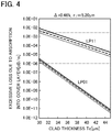
FIG. 4 is a diagram illustrating a calculation result of a relation of a clad thickness and an excessive loss of light due to absorption into the cover layer, when a relative refractive index difference of the core to the clad is 0.46% and a radius of the core is 5.20 µm. -
FIG. 5 is a diagram illustrating a calculation result of a relation of a clad thickness and an excessive loss of light due to absorption into the cover layer, when a relative refractive index difference of the core to the clad is 0.47% and a radius of the core is 5.22 µm. -
FIG. 6 is a diagram illustrating a calculation result of a relation of a bending radius of the multicore fiber and crosstalk. -
FIG. 7 is a cross-sectional view of a multicore fiber according to a second embodiment of the present invention, vertical to a longitudinal direction. -
FIG. 8 is a diagram illustrating a refractive index profile of core elements in the multicore fiber ofFIG. 7 . -
FIG. 9 is a diagram illustrating a calculation result of a relation of a clad thickness and an excessive loss of light due to absorption into a cover layer, when a relative refractive index difference of a core to a clad is 0.45% and a radius of the core is 6.11 µm. -
FIG. 10 is a diagram illustrating a calculation result of a relation of a clad thickness and an excessive loss of light due to absorption into the cover layer, when a relative refractive index difference of the core to the clad is 0.46% and a radius of the core is 6.12 µm. -
FIG. 11 is a diagram illustrating a calculation result of a relation of a clad thickness and an excessive loss of light due to absorption into the cover layer, when a relative refractive index difference of the core to the clad is 0.47% and a radius of the core is 6.12 µm. -
FIG. 12 is a diagram illustrating a calculation result of a relation of a bending diameter of the multicore fiber and crosstalk. -
FIG. 13 is a cross-sectional view of a multicore fiber according to a third embodiment of the present invention, vertical to a longitudinal direction. -
FIG. 14 is a side view of the multicore fiber ofFIG. 13 . -
FIG. 15 is a diagram illustrating a calculation result of a relation of a draw ratio and a propagation loss of light of an LP11 mode. -
FIG. 16 is a cross-sectional view of a multicore fiber according to a modification of the present invention, vertical to a longitudinal direction. - Hereinafter, preferred embodiments of a multicore fiber according to the present invention will be described in detail with reference to the drawings. To facilitate understanding, scales in the drawings and scales in the following description may be different from each other.
-
FIG. 1 is a diagram illustrating an aspect of a multicore fiber according to this embodiment. As illustrated inFIG. 1 , amulticore fiber 1 includes a plurality ofcore elements 10, a clad 20 that surrounds theindividual core elements 10 without clearance, and acover layer 30 that covers the clad 20. - One
core element 10 is disposed as a core element of a first layer at a center of the clad 20. The plurality ofcore elements 10 are disposed as core elements of a second layer at an outer circumferential side of thecore element 10 of the first layer, the plurality ofcore elements 10 are disposed as core elements of a third layer at outer circumferential sides of thecore elements 10 of the second layer, and the plurality ofcore elements 10 are disposed as core elements of a fourth layer at outer circumferential sides of thecore elements 10 of the third layer. As such, in this embodiment, the core elements are disposed by 1, 6, 12, and 12 in the four layers. A triangular lattice can be drawn by a line connecting centers of thecore elements 10 adjacent to each other and eachcore element 10 is disposed on each lattice point of the triangular lattice. In this way, the plurality ofcore elements 10 are disposed in a closest packing state. - In addition, each of the
core elements 10 has the same structure. Each of thecore elements 10 has a core 11, an inner clad 12 which surrounds an outer circumferential surface of thecore 11 without clearance, and a lowrefractive index layer 13 which surrounds an outer circumferential surface of the inner clad 12 without clearance and of which an outer circumferential surface is surrounded by the clad 20 without clearance. -
FIG. 2 is a diagram illustrating a refractive index profile of theindividual core elements 10 of themulticore fiber 1 illustrated inFIG. 1 . As illustrated inFIG. 2 , a refractive index of thecore 11 of thecore element 10 is higher than a refractive index of the inner clad 12 and a refractive index of the lowrefractive index layer 13 is lower than the refractive index of the inner clad 12 and a refractive index of the clad 20. As such, when eachcore element 10 is viewed from a viewpoint of the refractive index, each lowrefractive index layer 13 has a groove shape and eachcore element 10 has a trench structure. By the trench structure, confinement of light propagated through each core 11 of themulticore fiber 1 can be intensified. In this embodiment, the refractive index of the inner clad 12 is the same refractive index as the refractive index of the clad 20. - Because each
core element 10 of themulticore fiber 1 has the refractive index described above, the clad 20 and each inner clad 12 are made of quartz to which dopant is not added, eachfirst core 11 is made of quartz to which dopant such as germanium to increase a refractive index is added, and the lowrefractive index layer 13 is made of quartz to which dopant such as fluorine to decrease a refractive index is added. - In addition, each
core element 10 propagates light of an LP01 mode and light of an LP11 mode. In the light of the LP01 mode propagated through eachcore element 10, an effective area Aeff at a wavelength of 1550 nm is preferably almost equal to 80 µm2, from a viewpoint of connectivity with a standard single mode fiber. Here, combinations of a relative refractive index difference Δ of the core 11 to the clad 20 when an effective area Aeff of the light of the LP01 mode to be light of a wavelength of 1550 nm becomes 80 µm2 and a radius r1 of the core 11, in the case in which a relative refractive index difference Δt of the lowrefractive index layer 13 to the clad 20 is -0.7% and a ratio r2/r1 of the radius r1 of thecore 11 and a radius r2 of the inner clad 12 is 1.7, are shown in Table 1.Table 1 Δ [%] 0.4 0.41 0.42 0.43 0.44 0.45 0.46 0.47 0.48 0.49 0.5 r 1 [µm] 5 5.04 5.07 5.1 5.13 5.17 5.2 5.22 5.25 5.28 5.31 - In this case, the effective area Aeff of the light of the LP11 mode propagated through the core 11 at the wavelength of 1550 nm is roughly 92 µm2.
- In addition, the refractive index of the
cover layer 30 is higher than the refractive index of the clad 20. Thecover layer 30 has a property of absorbing light and light reaching thecover layer 30 from the clad 20 is absorbed into thecover layer 30 and disappears. As an example of a material configuring thecover layer 30, an ultraviolet curing resin can be used. - Next, a relation of an excessive loss of the light, propagated through the
core elements 10 disposed on the fourth layer to be outermost circumference, due to absorption into thecover layer 30 and a clad thickness will be described. As illustrated inFIG. 1 , a clad thickness Tc means a distance from a center of the core 11 disposed on the outermost circumference to an outer circumferential surface of the clad 20. In this embodiment, even if anycore element 10 disposed on the outermost circumference is used as a reference, the clad thickness Tc is constant. -
FIG. 3 is a diagram illustrating a calculation result of a relation of the clad thickness Tc and an excessive loss of light due to absorption into thecover layer 30, in the case in which the relative refractive index difference Δ of the core 11 to the clad 20 is 0.45% and the radius r1 of thecore 11 is 5.17 µm, in Table 1. InFIG. 3 , a solid line shows a state in which a ratio W/r1 of the radius r1 of thecore 11 and a thickness W of the lowrefractive index layer 13 is 0.8, a broken line shows a state in which the ratio W/r1 of the radius r1 of thecore 11 and the thickness W of the lowrefractive index layer 13 is 0.9, and a dotted line shows a state in which the ratio W/r1 of the radius r1 of thecore 11 and the thickness W of the lowrefractive index layer 13 is 1.0. In addition,FIG. 4 is a diagram illustrating a calculation result of a relation of the clad thickness Tc and the excessive loss of light due to absorption into thecover layer 30, in the case in which the relative refractive index difference Δ of the core 11 to the clad 20 is 0.46% and the radius r1 of thecore 11 is 5.20 µm. InFIG. 4 , a solid line shows a state in which the ratio W/r1 of the radius r1 of thecore 11 and the thickness W of the lowrefractive index layer 13 is 0.7, a broken line shows a state in which the ratio W/r1 of the radius r1 of thecore 11 and the thickness W of the lowrefractive index layer 13 is 0.8, and a dotted line shows a state in which the ratio W/r1 of the radius r1 of thecore 11 and the thickness W of the lowrefractive index layer 13 is 0.9. In addition,FIG. 5 is a diagram illustrating a calculation result of a relation of the clad thickness Tc and the excessive loss of light due to absorption into thecover layer 30, in the case in which the relative refractive index difference Δ of the core 11 to the clad 20 is 0.47% and the radius r1 of thecore 11 is 5.22 pm. InFIG. 5 , a solid line shows a state in which the ratio W/r1 of the radius r1 of thecore 11 and the thickness W of the lowrefractive index layer 13 is 0.6, a broken line shows a state in which the ratio W/r1 of the radius r1 of thecore 11 and the thickness W of the lowrefractive index layer 13 is 0.7, and a dotted line shows a state in which the ratio W/r1 of the radius r1 of thecore 11 and the thickness W of the lowrefractive index layer 13 is 0.8. - In calculations of
FIGS. 3 to 5 , the light of the LP01 mode is light in which a wavelength where an effective area Aeff is largest is 1625 nm in a C band and an L band and the light of the LP11 mode is light in which a wavelength where an effective area Aeff is smallest is 1530 nm in the C band and the L band. Generally, an optical fiber is not laid linearly and is bent and laid. Therefore, in the calculations ofFIGS. 3 to 5 , a bending radius of the multicore fiber is set to 140 mm. - As illustrated in
FIGS. 3 to 5 , it is seen that an excessive loss of the light of the LP01 mode due to absorption into thecover layer 30 becomes 0.001 dB/km or less in a region where the clad thickness Tc is roughly 31 µm. If it is considered that a propagation loss of the standard single mode fiber is 0.19 dB/km, a difference of 0.001 dB/km is a very small value. In addition, it is seen that an excessive loss of the light of the LP11 mode due to absorption into thecover layer 30 becomes 3 dB/km or more in a region where the clad thickness Tc is roughly 31 µm. If the excessive loss due to absorption into thecover layer 30 is 3 dB/km, the light is propagated through themulticore fiber 1 by 10 km, so that power can be set to 1/1000 or less. Therefore, propagation of the light of the LP11 mode unnecessary for signal transmission can be suppressed. - In
FIGS. 3 to 5 , it is seen that there is a solution in which the excessive loss of the light of the LP01 mode due to absorption into thecover layer 30 is 0.001 dB/km or less and the excessive loss of the light of the LP11 mode due to absorption into thecover layer 30 is 3 dB/km or more, in the region where the clad thickness Tc is roughly 31 µm. As such, inFIGS. 3 to 5 , in the C band and the L band, a wavelength of the light of the LP01 mode shows an excessive loss due to absorption into thecover layer 30 at a wavelength where the effective area Aeff is largest and a wavelength of the light of the LP11 mode shows an excessive loss due to absorption into thecover layer 30 at a wavelength where the effective area Aeff is smallest. Therefore, there is a combination of the clad thickness Tc and the radius r1 of the core 11 in which the light of the LP01 mode can be propagated at the excessive loss due to absorption into thesmall cover layer 30 not interfering with optical communication and the light of the LP11 mode can be sufficiently attenuated, when the light of the LP01 mode and the light of the LP11 mode are propagated in the same wavelength band. - Therefore, in the clad 20 of the
multicore fiber 1 according to this embodiment, a distance between each core 11 disposed on the outermost side in the clad 20 and thecover layer 30 is set to a distance at which the excessive loss of the light of the LP01 mode (primary LP mode), propagated through the core 11 disposed on the outermost side, due to absorption into thecover layer 30, becomes 0.001 dB/km or less and the excessive loss of the light of the LP11 mode (secondary LP mode), propagated through the core 11 disposed on the outermost side, due to absorption into thecover layer 30, becomes 3 dB/km or more. - For this reason, in the
multicore fiber 1 according to this embodiment, the light of the LP01 mode propagated through thecore element 10 disposed on the outermost circumference is affected by the excessive loss due to absorption into thecover layer 30 not interfering with the optical communication and power of the light of the LP11 mode propagated through thecore element 10 disposed on the outermost circumference is notably decreased by the excessive loss due to absorption into thecover layer 30. - Next, a relation of a core pitch and crosstalk will be described. The core pitch is an inter-center distance of the
cores 11 adjacent to each other. -
FIG. 6 is a diagram illustrating a calculation result of a relation of a bending radius of themulticore fiber 1 according to this embodiment and the crosstalk. In themulticore fiber 1 having the 31 core elements illustrated inFIG. 1 , if a clad diameter is set to 230 µm and a clad thickness Tc is set to 31 µm, a core pitch Λ becomes 32 µm. In the calculation ofFIG. 6 , a core pitch Λ is set to 32 µm, wavelengths of the light of the LP01 mode and the light of the LP11 mode are set to the wavelengths used in the calculations ofFIGS. 3 to 5 , and a ratio r2/r1 of the radius r1 of thecore 11 and the radius r2 of the inner clad 12 is set under the same conditions as the conditions of the case of Table 1. InFIG. 6 , a solid line shows a result in which the relative refractive index difference Δ of the core 11 to the clad 20 and the radius of the core 11, used in the calculation ofFIG. 3 , are used and the ratio W/r1 of the radius r1 of thecore 11 and the thickness W of the lowrefractive index layer 13 is calculated as 0.9. In addition, a broken line shows a result in which the relative refractive index difference Δ of the core 11 to the clad 20 and the radius of the core 11, used in the calculation ofFIG. 4 , are used and the ratio W/r1 of the radius r1 of thecore 11 and the thickness W of the lowrefractive index layer 13 is calculated as 0.8. In addition, a dotted line shows a result in which the relative refractive index difference Δ of the core 11 to the clad 20 and the radius of the core 11, used in the calculation ofFIG. 5 , are used and the ratio W/r1 of the radius r1 of thecore 11 and the thickness W of the lowrefractive index layer 13 is calculated as 0.7. - As illustrated in
FIG. 6 , a result in which the crosstalk of the light of the LP01 mode is smaller than -40 dB/km in all cases is obtained. In addition, a result in which the crosstalk of the light of the LP11 mode is larger than -30 dB/km in all cases is obtained. That is, in the case of the above conditions, if the core pitch is 32 µm, the crosstalk of the light of the LP01 mode can be set to - 40 dB/km or less and the crosstalk of the light of the LP11 mode can be set to -30 dB/km or more. InFIG. 6 , in the C band and the L band, the wavelength of the light of the LP01 mode is calculated as a wavelength where an effective area Aeff is largest and the wavelength of the light of the LP11 mode is calculated as a wavelength where the effective area Aeff is smallest. Therefore, there is the core pitch Λ where the crosstalk of the light of the LP01 mode can be set to a small value not interfering with the optical communication and the crosstalk of the light of the LP11 mode can be set to a large value, when the light of the LP01 mode and the light of the LP11 mode are propagated in the same wavelength band. - Therefore, the core pitch Λ of the
multicore fiber 1 according to this embodiment is set to a distance at which the crosstalk of the light of the LP01 mode (primary LP mode) becomes -40 dB/km or less and the crosstalk of the light of the LP11 mode (secondary LP mode) becomes -30 dB/km or more. - For this reason, in the
multicore fiber 1 according to this embodiment, the crosstalk of the light of the LP01 mode propagated through eachcore element 10 is suppressed. However, the light of the LP11 mode propagated through eachcore element 10 is moved by the crosstalk. Therefore, the light of the LP11 mode propagated through the first to third layers can be moved to thecore element 10 of the fourth layer to be the outermost circumference by the crosstalk. - As described above, according to the
multicore fiber 1 according to this embodiment, because eachcore element 10 is a core element propagating light of a higher-order mode by a 1 mode as compared with the core element propagating the light of only the LP01 mode (primary LP mode), confinement of the light of the LP01 mode in the core 11 can be intensified. Therefore, the crosstalk of the light of the LP01 mode can be suppressed as compared with the core propagating only the light of the LP01 mode. For this reason, a degree of freedom for designing the core pitch and a degree of freedom for designing a refractive index or a diameter of each core are improved as compared with the multicore fiber propagating only the light of the LP01 mode. - In addition, the distance between the core 11 disposed on the outermost side and the cover layer, that is, the clad thickness Tc is set to a magnitude at which the excessive loss of the light of the LP01 mode, propagated through the core 11 disposed on the outermost side, due to absorption into the
cover layer 30, becomes 0.001 dB/km or less and the excessive loss of the light of the LP11 mode, propagated through the core 11 disposed on the outermost side, due to absorption into thecover layer 30, becomes 3 dB/km or more. Therefore, the light of the LP11 mode that is propagated through the core 11 located at the outermost side in the clad and is unnecessary for communication is absorbed into thecover layer 30 and is lost. In addition, the core pitch Λ is set to a distance at which the crosstalk of the light of the LP01 mode becomes -40 dB/km or less and the crosstalk of the light of the LP11 mode becomes -30 dB/km or more. Therefore, the crosstalk of the light of the LP01 mode used for the communication is suppressed and the crosstalk of the light of the LP11 mode to be light unnecessary for the communication occurs. As a result, the light of the LP11 mode can be moved to the core 11 disposed on the outermost side in the clad 20 by the crosstalk. In this way, the light of the LP11 mode propagated through the core 11 disposed on the inner circumferential side of the clad 20 is moved to the core 11 disposed on the outermost side of the clad 20 and is absorbed into thecover layer 30. Therefore, according to themulticore fiber 1 according to this embodiment, the crosstalk of the LP01 mode used for signal transmission can be improved while the propagation of the light of the LP11 mode not used for the signal transmission is suppressed. - Next, a second embodiment of the present invention will be described in detail with reference to
FIGS. 7 to 12 . Components equal to or equivalent to those in the first embodiment are denoted with the same reference numerals and overlapped description is omitted except for the case in which description is given particularly. -
FIG. 7 is a cross-sectional view of a multicore fiber according to this embodiment, vertical to a longitudinal direction, andFIG. 8 is a diagram illustrating a refractive index profile of core elements in amulticore fiber 2 ofFIG. 7 . As illustrated inFIGS. 7 and8 , themulticore fiber 2 according to this embodiment is different from themulticore fiber 1 according to the first embodiment in that eachcore element 10 does not have an inner clad 12 and acore 11 is surrounded by a lowrefractive index layer 13 directly. - Even in this embodiment, each
core element 10 propagates light of an LP01 mode and light of an LP11 mode. In addition, even in this embodiment, an effective area Aeff of the light of the LP01 mode propagated through each core element is preferably larger than 80 µm2, from the same reason as the first embodiment. Here, combinations of a relative refractive index difference Δ of the core 11 to a clad 20 when an effective area Aeff of the light of the LP01 mode to be light of a wavelength of 1550 nm becomes 80 µm2 and a radius r1 of the core 11, in the case in which a relative refractive index difference Δt of the lowrefractive index layer 13 to the clad 20 is -0.7%, are shown in Table 2.Table 2 Δ [%] 0.4 0.41 0.42 0.43 0.44 0.45 0.46 0.47 0.48 0.49 0.5 r 1 [µm] 6.08 6.08 6.09 6.1 6.1 6.11 6.12 6.12 6.13 6.14 6.14 - In this case, an effective area Aeff of the light of the LP11 mode propagated through the
core 11 is roughly 119 µm2. - Next, a relation of an excessive loss of the light, propagated through the
core elements 10 disposed on a fourth layer to be outermost circumference, due to absorption into acover layer 30 and a clad thickness will be described in the same way as the first embodiment. - Similarly to
FIG. 3 ,FIG. 9 is a diagram illustrating a calculation result of a relation of a clad thickness Tc and an excessive loss of light due to absorption into thecover layer 30, in the case in which a relative refractive index difference Δ of the core 11 to the clad 20 is 0.45% and a radius of thecore 11 is 6.11 µm. Similarly toFIG. 4 ,FIG. 10 is a diagram illustrating a calculation result of a relation of the clad thickness Tc and the excessive loss of light due to absorption into thecover layer 30, in the case in which the relative refractive index difference Δ of the core 11 to the clad 20 is 0.46% and the radius r1 of thecore 11 is 6.12 µm. Similarly toFIG. 5 ,FIG. 11 is a diagram illustrating a calculation result of a relation of the clad thickness Tc and the excessive loss of light due to absorption into thecover layer 30, in the case in which the relative refractive index difference Δ of the core 11 to the clad 20 is 0.47% and the radius r1 of thecore 11 is 6.12 µm. - In calculations of
FIGS. 9 to 11 , similarly to the first embodiment, a wavelength of the light of the LP01 mode is set to 1625 nm and a wavelength of the light of the LP11 mode is set to 1530 nm. In addition, in the calculations ofFIGS. 9 to 12 , a bending radius of the multicore fiber is set to 140 mm, from the same reason as the first embodiment. - As illustrated in
FIGS. 9 to 11 , even in this embodiment, in the light of the LP01 mode, an excessive loss due to absorption into thecover layer 30 becomes 0.001 dB/km or less in a region where the clad thickness Tc is roughly 31 µm and in the light of the LP11 mode, an excessive loss due to absorption into thecover layer 30 becomes 3 dB/km or more in a region where the clad thickness Tc is roughly 31 µm. Therefore, it is seen that there is a solution in which the excessive loss of the light of the LP01 mode due to absorption into thecover layer 30 is 0.001 dB/km or less and the excessive loss of the light of the LP11 mode due to absorption into thecover layer 30 is 3 dB/km or more, in the region where the clad thickness Tc is roughly 31 µm. In the calculations ofFIGS. 9 to 11 , in a C band and an L band, a wavelength of the light of the LP01 mode is a wavelength where the effective area Aeff is largest and a wavelength of the light of the LP11 mode is a wavelength where the effective area Aeff is smallest. Therefore, there is a combination of the clad thickness Tc and the radius r1 of the core 11 in which the light of the LP01 mode can be propagated at the excessive loss due to absorption into thesmall cover layer 30 not interfering with optical communication and the light of the LP11 mode unnecessary for communication can be sufficiently attenuated. - Therefore, similarly to the
multicore fiber 1 according to the first embodiment in which the light is propagated through the core 11 disposed on the outermost side, with respect to the clad thickness Tc of themulticore fiber 2 according to this embodiment, a distance between the core 11 disposed on the outermost side in the clad 20 and thecover layer 30 is set to a distance at which the excessive loss of the light of the LP01 mode, propagated through the core 11 disposed on the outermost side, due to absorption into thecover layer 30, becomes 0.001 dB/km or less and the excessive loss of the light of the LP11 mode, propagated through the core 11 disposed on the outermost side, due to absorption into thecover layer 30, becomes 3 dB/km or more. - Next, a relation of a core pitch and crosstalk according to this embodiment will be described.
-
FIG. 12 is a diagram illustrating a calculation result of a relation of a bending radius of themulticore fiber 2 according to this embodiment and the crosstalk. In themulticore fiber 1 having the 31 core elements illustrated inFIG. 7 , similarly to the first embodiment, a core pitch Λ is set to 32 µm and a wavelength of the light of the LP01 mode and a wavelength of the light of the LP11 mode are set to the wavelengths used in the calculations ofFIGS. 9 to 11 . InFIG. 12 , a solid line shows a result in which a relative refractive index difference Δ of the core 11 to the clad 20 and the radius of the core 11, used in the calculation ofFIG. 9 , are used and a ratio W/r1 of a radius r1 of thecore 11 and a thickness W of the lowrefractive index layer 13 is calculated as 0.9. In addition, a broken line shows a result in which the relative refractive index difference Δ of the core 11 to the clad 20 and the radius of the core 11, used in the calculation ofFIG. 10 , are used and the ratio W/r1 of the radius r1 of thecore 11 and the thickness W of the lowrefractive index layer 13 is calculated as 0.8. In addition, a dotted line shows a result in which the relative refractive index difference Δ of the core 11 to the clad 20 and the radius of the core 11, used in the calculation ofFIG. 11 , are used and the ratio W/r1 of the radius r1 of thecore 11 and the thickness W of the lowrefractive index layer 13 is calculated as 0.7. - As illustrated in
FIG. 12 , even in this embodiment, a result in which the crosstalk of the light of the LP01 mode is smaller than -40 dB/km in all cases is obtained and a result in which the crosstalk of the light of the LP11 mode is larger than -30 dB/km in all cases is obtained. That is, in the case of the above conditions, if the core pitch is 32 µm, the crosstalk of the light of the LP01 mode can be set to -40 dB/km or less and the crosstalk of the light of the LP11 mode can be set to -30 dB/km or more. InFIG. 12 , in the C band and the L band, the wavelength of the light of the LP01 mode is calculated as a wavelength where an effective area Aeff is largest and the wavelength of the light of the LP11 mode is calculated as a wavelength where the effective area Aeff is smallest. Therefore, similarly to the first embodiment, even in this embodiment, there is the core pitch Λ where the crosstalk of the light of the LP01 mode can be set to a small value not interfering with the optical communication and the crosstalk of the light of the LP11 mode can be set to a large value, when the light of the LP01 mode and the light of the LP11 mode are propagated in the same wavelength band. - Therefore, the core pitch Λ of the
multicore fiber 2 according to this embodiment is set to a distance at which the crosstalk of the light of the LP01 mode (primary LP mode) becomes -40 dB/km or less and the crosstalk of the light of the LP11 mode (secondary LP mode) becomes -30 dB/km or more. - Even in the
multicore fiber 2 according to this embodiment, from the same reason as themulticore fiber 1 according to the first embodiment, the crosstalk of the LP01 mode can be improved while the propagation of the light of the LP11 mode is suppressed. - Next, a third embodiment of the present invention will be described in detail with reference to
FIGS. 13 to 15 . Components equal to or equivalent to those in the first embodiment are denoted with the same reference numerals and overlapped description is omitted except for the case in which description is given particularly. -
FIG. 13 is a diagram illustrating an aspect of a multicore fiber according to this embodiment. As illustrated inFIG. 13 , in amulticore fiber 3 according to this embodiment, eachcore element 10 has the same configuration as the configuration of thecore element 10 in themulticore fiber 1 according to the first embodiment. Therefore, even in this embodiment, eachcore element 10 is configured to propagate light of an LP01 mode and light of an LP11 mode. In themulticore fiber 1 according to the first embodiment, because theindividual core elements 10 are disposed in a closest packing state, a line connectingindividual cores 11 becomes a triangular lattice. However, in themulticore fiber 3 according to this embodiment, a line connecting theindividual cores 11 becomes a square lattice. - In a clad 20 of the
multicore fiber 3 according to this embodiment, a distance between each of the fourcores 11 disposed on an outermost side in the clad 20 and acover layer 30 is set to a distance at which an excessive loss of the light of the LP01 mode (primary LP mode), propagated through thecores 11 disposed on the outermost side, due to absorption into thecover layer 30, becomes 0.001 dB/km or less and an excessive loss of the light of the LP11 mode (secondary LP mode), propagated through thecores 11 disposed on the outermost side, due to absorption into thecover layer 30, becomes 3 dB/km or more. Similarly to themulticore fiber 1 according to the first embodiment, a core pitch Λ of themulticore fiber 3 according to this embodiment is set to a distance at which the crosstalk of the light of the LP01 mode becomes -40 dB/km or less and the crosstalk of the light of the LP11 mode becomes -30 dB/km or more. For example, the core pitch Λ of themulticore fiber 3 is set to 31.8 µm, a clad thickness Tc is set to 31 µm, and a diameter of the clad 20 is set to 197 µm. In this embodiment, a distance from a center of each of the fourcores 11 disposed on the outermost side to an outer circumferential surface of the clad 20 becomes a clad thickness. - Therefore, even in the
multicore fiber 3 according to this embodiment, from the same reason as themulticore fiber 1 according to the first embodiment, the crosstalk of the LP01 mode can be improved while the propagation of the light of the LP11 mode is suppressed. -
FIG. 14 is a side view of themulticore fiber 3 ofFIG. 13 . However, inFIG. 14 , thecover layer 30 is omitted to facilitate understanding. As illustrated inFIG. 14 , themulticore fiber 3 according to this embodiment further includes an extension portion BP that extends such that diameters of the plurality ofcores 11 decrease, in a part of the plurality ofcores 11 in a longitudinal direction. The extension portion BP is extended by partially removing thecover layer 30 of themulticore fiber 3, heating themulticore fiber 3 from the outside of the clad 20, and drawing themulticore fiber 3. -
FIG. 15 is a diagram illustrating a calculation result of a relation of a draw ratio and a propagation loss of the light of the LP11 mode. When the calculation ofFIG. 15 is performed, a relative refractive index difference Δt of a lowrefractive index layer 13 to the clad 20 is set to -0.7%, a ratio r2/r1 of a radius r1 of thecore 11 and a radius r2 of an inner clad 12 is set to 1.7, a relative refractive index difference Δ of the core 11 to the clad 20 is set to 0.45%, the radius of thecore 11 is set to 5.17 µm, and a ratio W/r1 of the radius r1 of thecore 11 and a thickness W of the lowrefractive index layer 13 is set to 0.9. FromFIG. 15 , if a diameter reduction ratio of the extension portion BP to a non-extension portion is set to about 0.6, that is, a diameter of each member of themulticore fiber 3 in the extension portion BP is set to 0.6 times as large as a diameter of each member of themulticore fiber 3 in the diameter non-reduction portion, it can be anticipated that a loss of the light of the LP11 mode propagated through thecore element 10 becomes 10 dB/cm. Therefore, the extension portion BP of the diameter reduction ratio of about 0.6 is provided by about 2 cm, so that the light of the LP11 mode can be eliminated not to obstruct optical communication. In this case, in the LP01 mode to be a basic mode, a loss of light due to extension is little as 0.001 dB or less and rarely affects the optical communication. - According to this embodiment, the light of the LP11 mode can be eliminated by the
cover layer 30, the extension portion BP is provided, so that the light of the LP11 mode can be caused to be further lost, and light of a mode unnecessary for communication can be eliminated more appropriately. - The present invention has been described using the embodiments as the examples. However, the present invention is not limited thereto.
- For example, even in the
multicore fiber 1 according to the first embodiment and themulticore fiber 2 according to the second embodiment, the extension portion BP provided in themulticore fiber 3 according to the third embodiment may be provided. In this case, in themulticore fibers - In addition, in the first and second embodiments, the 31
core elements 10 are disposed in a closest packing state and in the third embodiment, the 16core elements 10 are disposed in a square lattice shape. However, the number of cores in the multicore fiber according to the present invention is not limited to the above number, as long as the number is plural.FIG. 16 is a cross-sectional view of a multicore fiber according to a modification of the present invention. In describing this modification, components equal to or equivalent to those in the first embodiment are denoted with the same reference numerals and overlapped description is omitted except for the case in which description is given particularly. As illustrated inFIG. 16 , amulticore fiber 4 according to this modification is different from themulticore fiber 1 according to the first embodiment in that onecore element 10 is disposed as a core element of a first layer at a center of a clad 20, a plurality ofcore elements 10 are disposed as core elements of a second layer on an outer circumferential side of thecore element 10 of the first layer, and no core element is disposed on outer circumferential sides of thecore elements 10 of the second layer. Even in the multicore fiber of the 1-6 arrangement, thecore element 10 is equal to thecore element 10 of themulticore fiber 1 according to the first embodiment, the core pitch Λ is equal to the core pitch Λ of themulticore fiber 1 according to the first embodiment, and a clad thickness Tc is equal to the clad thickness Tc of themulticore fiber 1 according to the first embodiment. As a result, from the same reason as themulticore fiber 1 according to the first embodiment, the crosstalk of the LP01 mode can be improved while the propagation of the light of the LP11 mode is suppressed. - In addition, in the embodiments and the modification, the
multicore fiber 1 is configured such that the single mode communication is performed using the light of the LP01 mode in the communication band, each core 11 propagates the light of the LP01 mode and the light of the LP11 mode, and the light of the LP11 mode is eliminated. However, the present invention is not limited thereto. That is, the present invention can be used in the case in which few-mode communication or multi-mode communication is performed and each core may be configured to propagate light up to a higher-order mode by a 1 LP mode as compared with a mode used for communication and the light of the higher-order mode by the 1 LP mode may be eliminated by the cover layer. Specifically, the multicore fiber according to the present invention is a multicore fiber for performing communication using light up to an xth-order LP mode (where x is an integer of 1 or more) in a communication band. Each of the plurality ofcores 11 propagates light up to an (x + 1)th-order LP mode. The core pitch Λ is set to a distance at which crosstalk of the light up to the xth-order LP mode becomes -40 dB/km or less and crosstalk of light of the (x + 1)th-order LP mode becomes -30 dB/km or more. The distance between the core 11 disposed on the outermost side in the clad 20 and thecover layer 30 is set to a distance at which an excessive loss of the light up to the xth-order LP mode, propagated through the core disposed on the outermost side, due to absorption into the cover layer becomes 0.001 dB/km or less and an excessive loss of the light of the (x + 1)th-order LP mode, propagated through the core disposed on the outermost side, due to absorption into the cover layer becomes 3 dB/km or more. - According to the multicore fiber, because each core 11 is the core propagating the light of the higher-order mode by the 1 mode as compared with the core propagating the light up to the xth-order LP mode, confinement of the light up to the xth-order LP mode in the core is intensified and the crosstalk is improved. Meanwhile, an effective area of the light up to the (x + 1)th-order LP mode is larger than an effective area of the light of the xth-order LP mode. By using this, the distance between the core 11 disposed on the outermost side in the clad 20 and the cover layer can be set to a distance at which the excessive loss of the light up to the xth-order LP mode, propagated through the core disposed on the outermost side, due to absorption into the cover layer becomes 0.001 dB/km or less and the excessive loss of the light of the (x + 1)th-order LP mode, propagated through the core disposed on the outermost side, due to absorption into the cover layer becomes 3 dB/km or more. Therefore, the light of the (x + 1)th-order LP mode that is propagated through the core 11 located at the outermost side in the clad 20 and is unnecessary for the communication is absorbed into the
cover layer 30 and is lost. By using a fact that the effective area of the light up to the (x + 1)th-order LP mode is larger than the effective area of the light of the xth-order LP mode, the core pitch Λ can be set to the distance at which the crosstalk of the light up to the xth-order LP mode becomes -40 dB/km or less and the crosstalk of the light of the (x + 1)th-order LP mode becomes -30 dB/km or more. Therefore, the crosstalk of the light up to the xth-order LP mode used for the communication is suppressed and the crosstalk of the light of the (x + 1)th-order LP mode to be light unnecessary for the communication occurs. As a result, the light of the (x + 1)th-order LP mode can be moved to the core 11 located at the outermost side in the clad 20 by the crosstalk and is absorbed into thecover layer 30 as described above. In this way, the light up to the xth-order LP mode is propagated and the crosstalk of the light up to the xth-order mode is improved. - As such, even when the multicore fiber performs the communication using the light up to the xth-order LP mode in the communication band, the extension portion BP according to the third embodiment is preferably provided. In this case, in the extension portion BP, the loss of the light of the (x + 1)th-order LP mode is preferably 20 dB or more and the excessive loss of the light of the xth-order LP mode is more preferably 0.001 dB or less.
- In addition, in the embodiments and the modification, each core 11 is configured to be surrounded by the low
refractive index layer 13. However, the present invention is not limited thereto. For example, each core 11 may be surrounded by the clad 20 directly. Even in this case, design is enabled, in which each of the plurality ofcores 11 propagates the light up to the (x + 1)th-order LP mode, the core pitch Λ is set to the distance at which the crosstalk of the light up to the xth-order LP mode becomes -40 dB/km or less and the crosstalk of the light of the (x + 1)th-order LP mode becomes -30 dB/km or more, and the distance between the core 11 disposed on the outermost side in the clad 20 and thecover layer 30 can be set to the distance at which the excessive loss of the light up to the xth-order LP mode, propagated through the core 11 disposed on the outermost side, due to absorption into thecover layer 30 becomes 0.001 dB/km or less and the excessive loss of the light of the (x + 1)th-order LP mode, propagated through the core 11 disposed on the outermost side, due to absorption into thecover layer 30 becomes 3 dB/km or more. - Hereinafter, contents of the present invention will be described more specifically using examples and comparative examples. However, the present invention is not limited thereto.
- The
multicore fiber 1 according to the first embodiment was manufactured. An average value of the core pitch Λ of the manufacturedmulticore fiber 1 became 31.6 µm, an average value of the clad thickness Tc became 31.5 µm, an average value of the clad diameter became 231.0 µm, and an average value of an outer diameter of thecover layer 30 became 334.8 µm. In addition, a length was 11.2 km. The propagation loss of the light of the LP01 mode propagated through themulticore fiber 1 was measured. In addition, polarization mode dispersion PMD, a polarization loss difference PDL, an effective area Aeff, and a cable cutoff wavelength λc were measured. Results thereof are shown in Table 3. In Table 3, thecores 1 to 12 show the cores of the fourth layer in the first embodiment, thecores 13 to 24 show the cores of the third layer in the first embodiment, the cores 25 to 30 show the cores of the second layer in the first embodiment, and the core 31 shows the core of the first layer in the first embodiment.Table 3 Propagation loss [dB/km] PMD 
PDL A eff λcc LP01 [dB] [µm2] [µm] Core 1550 nm 1625 nm 1530-1625 nm 1550 nm 1625 nm - 1 0.294 0.3 0.12 0.08 76.1 79.6 1.71 2 0.293 0.292 3 0.277 0.289 1.66 4 0.279 0.294 5 0.282 0.291 75.2 79.4 1.66 6 0.281 0.289 1.69 7 0.291 0.298 0.11 0.09 1.68 8 0.293 0.298 9 0.282 0.292 1.7 10 0.286 0.286 0.1 0.08 1.7 11 0.285 0.282 74.7 79.7 1.67 12 0.29 0.299 13 0.283 0.293 0.26 0.11 74.3 80.8 1.75 14 0.264 0.275 15 0.277 0.289 74 78.9 16 0.256 0.269 0.15 0.06 2.02 17 0.277 0.289 18 0.272 0.282 19 0.293 0.298 0.27 0.06 74.9 80.4 1.71 20 0.286 0.294 21 0.286 0.292 1.77 22 0.271 0.273 0.19 0.07 2.04 23 0.293 0.297 24 0.274 0.274 2.03 25 0.26 0.264 0.07 0.07 74.3 80.8 1.99 26 0.274 0.27 27 0.287 0.294 2.04 28 0.261 0.266 0.14 0.07 75.7 78.4 29 0.253 0.268 0.12 0.08 2.05 30 0.25 0.265 31 0.245 0.257 0.1 0.04 75 78.2 2.04 - Losses other than the excessive loss due to absorption into the cover layer are included in the loss of the light propagated through the cores. For this reason, from Table 3, it is thought that the excessive loss of the light of the LP01 mode, propagated through the
cores 1 to 12, due to absorption into the cover layer becomes 0.001 dB/km or less. - Next, the crosstalk of the
cores 11 adjacent to each other was measured. The measurement of the crosstalk of the light of the LP01 mode was performed by calculating the crosstalk from wavelength dependency of the crosstalk of the light of the LP01 mode in a band of a cutoff wavelength or more. In addition, the measurement of the crosstalk of the light of the LP11 mode was performed by converting light from a wavelength variable light source into the light of the LP11 mode by a mode converter, causing the light to be incident on the specific core, connecting a 2-mode optical fiber to the measured core adjacent to the core, receiving light emitted from the 2-mode optical fiber, and calculating the crosstalk. Results thereof are shown in Table 4. The cores described in a first column of Table 4 and the cores described in a second column thereof are cores adjacent to each other.Table 4 Excited core Measured core 11.2 km (Measured XT) XT11-11 XT01-01 8 9 -5.6 -38.5 19 -8.2 -38.8 20 -7.7 -38.8 17 5 -8.7 -41 6 -5.8 -39.5 16 -8.1 -37.5 27 -6.4 -37.8 22 10 -6 -39.8 23 -2.4 -38.1 29 -4.6 -39.5 26 14 -5.7 -39.1 15 -4.9 -39.8 25 -5.3 -38.1 31 -4.1 -36.3 31 25 -3.8 -37.8 27 -3.7 -36.7 29 -3 -34.7 Average -5.5 -38.4 Maximum -2.4 -34.7 Minimum -8.7 -41 - As shown in Table 4, a result in which the crosstalk of the light of the LP11 mode is larger than the crosstalk of the light of the LP01 mode or the crosstalk of the light of the LP01 mode and the light of the LP11 mode and the light of the LP11 mode can be moved to the outermost core by the crosstalk while the crosstalk of the LP01 mode is suppressed was obtained.
- The
multicore fiber 2 according to the second embodiment was manufactured. An average value of the core pitch Λ of the manufacturedmulticore fiber 2 became 32.1 µm, an average value of the clad thickness Tc became 31.2 µm, an average value of the clad diameter became 230.8 µm, and an average value of an outer diameter of thecover layer 30 became 337.0 µm. In addition, a length was 10.5 km. Similarly to the first example, with respect to themulticore fiber 1, the crosstalk of thecores 11 adjacent to each other was measured. Results thereof are shown in Table 5. The cores described in a first column of Table 5 and the cores described in a second column thereof are cores adjacent to each other.Table 5 Excited core Measured core 10.5 km (Measured XT) XT11-11 XT01-01 8 9 -9.2 -43 19 -11.8 -43.3 20 -11.3 -43.3 17 5 -12.3 -45.5 6 -9.4 -44 16 -11.7 -42 27 -10 -42.3 22 10 -9.6 -44.3 23 -6 -42.6 29 -8.2 -44 26 14 -9.3 -43.6 15 -8.5 -44.3 25 -8.9 -42.6 31 -7.7 -40.8 31 25 -7.4 -42.3 27 -7.3 -41.2 29 -6.6 -39.2 - As shown in Table 5, a result in which the crosstalk of the light of the LP11 mode is larger than the crosstalk of the light of the LP01 mode or the crosstalk of the light of the LP01 mode and the light of the LP11 mode and the light of the LP11 mode can be moved to the outermost core by the crosstalk while the crosstalk of the LP01 mode is suppressed was obtained.
- The
multicore fiber 4 according to the modification was manufactured. An average value of the core pitch Λ of the manufacturedmulticore fiber 4 became 32.4 µm, an average value of the clad thickness Tc became 29.9 µm, an average value of the clad diameter became 124.4 µm, and an average value of an outer diameter of thecover layer 30 became 220.0 µm. In addition, a length was 10.0 km. Similarly to the first example, with respect to themulticore fiber 4, propagation losses of the light of the LP01 mode and the light of the LP11 mode, polarization mode dispersion PMD, a polarization loss difference PDL, an effective area Aeff, and a cable cutoff wavelength λc were measured. Results thereof are shown in Table 6. In Table 6, thecores 1 to 6 show the cores disposed on the outer circumferential side and the core 7 shows the core disposed on the center of the clad.Table 6 Propagation loss [dB/km] PMD 
PDL A eff λcc LP01 [dB] [µm2] [µm] Core 1550 nm 1625 nm 1530-1625 nm 1550 nm 1625 nm - 1 0.226 0.24 76.1 79.6 1.66 2 0.229 0.238 3 0.245 0.256 1.69 4 0.23 0.238 0.177 0.15 5 0.225 0.233 75.2 79.4 1.69 6 0.227 0.237 1.69 7 0.225 0.234 0.201 0.1 2.1 - From Table 6, it is thought that the excessive loss of the light of the LP01 mode, propagated through the
cores 1 to 6, due to absorption into the cover layer becomes 0.001 dB/km or less. - From the results of the examples described above, it was confirmed that the crosstalk of the light of the LP01 mode is suppressed and the crosstalk of the light of the LP11 mode occurs, according to the multicore fiber according to the present invention. In addition, in the examples, it is thought that the excessive loss of the light, propagated through the core disposed on the outermost side, due to absorption into the cover layer becomes 0.001 dB/km or less, from the propagation loss of the light of the LP01 mode, and it is thought that the excessive loss of the light, propagated through the core disposed on the outermost side, due to absorption into the cover layer becomes 3 dB/km or more, when the propagation loss of the light of the LP01 mode is measured.
- As described above, according to the present invention, a multicore fiber capable of improving a degree of freedom for design can be provided and the multicore fiber can be used in a field of optical communication.
-
- 1 to 4 ... multicore fiber
- 10 ... core element
- 11 ... core
- 12 ... inner clad
- 13 ... low refractive index layer
- 20 ... clad
- 30 ... cover layer
- BP ... extension portion
- Tc ... clad thickness
- Λ ... core pitch
Claims (4)
- A multicore fiber for performing communication using light up to an xth-order LP mode (where x is an integer of 1 or more) in a communication band, the multicore fiber comprising:a plurality of cores;a clad that surrounds the plurality of cores and has a refractive index lower than refractive indexes of the plurality of cores; anda cover layer that covers the clad and has a refractive index higher than the refractive index of the clad,wherein each of the plurality of cores propagates light up to an (x + 1)th-order LP mode,a core pitch is set to a distance at which crosstalk of the light up to the xth-order LP mode becomes -40 dB/km or less and crosstalk of light of the (x + 1)th-order LP mode becomes -30 dB/km or more, anda distance between the core disposed on an outermost side in the clad and the cover layer is set to a distance at which an excessive loss of the light up to the xth-order LP mode, propagated through the core disposed on the outermost side, due to absorption into the cover layer becomes 0.001 dB/km or less and an excessive loss of the light of the (x + 1)th-order LP mode, propagated through the core disposed on the outermost side, due to absorption into the cover layer becomes 3 dB/km or more.
- The multicore fiber according to claim 1, further comprising:an extension portion that extends such that diameters of the plurality of cores decrease, in a part of the plurality of cores in a longitudinal direction,wherein, in the extension portion, the plurality of cores propagate the light up to the xth-order LP mode and propagation of the light of the (x + 1)th-order LP mode is suppressed.
- The multicore fiber according to claim 2, wherein, in the extension portion, a loss of the light of the (x + 1)th-order LP mode is 20 dB or more.
- The multicore fiber according to any one of claims 1 to 3, wherein x is 1.
Applications Claiming Priority (2)
| Application Number | Priority Date | Filing Date | Title |
|---|---|---|---|
| JP2015093422A JP6532748B2 (en) | 2015-04-30 | 2015-04-30 | Multicore fiber |
| PCT/JP2016/063077 WO2016175209A1 (en) | 2015-04-30 | 2016-04-26 | Multicore fiber |
Publications (2)
| Publication Number | Publication Date |
|---|---|
| EP3290970A1 true EP3290970A1 (en) | 2018-03-07 |
| EP3290970A4 EP3290970A4 (en) | 2019-01-16 |
Family
ID=57199564
Family Applications (1)
| Application Number | Title | Priority Date | Filing Date |
|---|---|---|---|
| EP16786486.7A Withdrawn EP3290970A4 (en) | 2015-04-30 | 2016-04-26 | FIBER MULTIC UR |
Country Status (5)
| Country | Link |
|---|---|
| US (1) | US10101526B2 (en) |
| EP (1) | EP3290970A4 (en) |
| JP (1) | JP6532748B2 (en) |
| CN (1) | CN107111053B (en) |
| WO (1) | WO2016175209A1 (en) |
Families Citing this family (15)
| Publication number | Priority date | Publication date | Assignee | Title |
|---|---|---|---|---|
| JP6340342B2 (en) * | 2015-05-27 | 2018-06-06 | 株式会社フジクラ | Multi-core fiber |
| CN114252953A (en) | 2017-08-31 | 2022-03-29 | 旭化成株式会社 | Plastic optical fiber, plastic optical fiber cable with connector, optical communication system, and plastic optical fiber sensor |
| CN109541754A (en) * | 2017-09-22 | 2019-03-29 | 北京万集科技股份有限公司 | A kind of optical coupling structure and its manufacturing method |
| JP6715372B1 (en) * | 2019-04-25 | 2020-07-01 | 日本電信電話株式会社 | Multi-core optical fiber and design method |
| CN114829998B (en) * | 2019-12-04 | 2023-12-26 | 爱尔康公司 | Multi-core optical fiber with reduced bubble formation |
| JP7501019B2 (en) * | 2020-03-19 | 2024-06-18 | 住友電気工業株式会社 | Multi-core optical fiber |
| JP7543789B2 (en) * | 2020-09-01 | 2024-09-03 | 住友電気工業株式会社 | Multi-core optical fiber and multi-core optical fiber cable |
| JP7528711B2 (en) * | 2020-10-16 | 2024-08-06 | 住友電気工業株式会社 | Multi-core optical fiber and multi-core optical fiber cable |
| JP2021058806A (en) * | 2021-01-21 | 2021-04-15 | 株式会社三洋物産 | Game machine |
| US11726257B2 (en) | 2021-03-05 | 2023-08-15 | Corning Incorporated | Multicore optical fiber |
| CN113568091A (en) * | 2021-08-06 | 2021-10-29 | 华中科技大学 | Axial polarization maintaining multi-core optical fiber |
| US12032200B2 (en) * | 2021-12-28 | 2024-07-09 | Sterlite Technologies Limited | Trench assisted multi-core optical fiber with reduced crosstalk |
| EP4388355A1 (en) * | 2022-10-12 | 2024-06-26 | OFS Fitel, LLC | Mitigating cross-talk in multi-core optical fiber under micro-bending |
| JPWO2024166598A1 (en) * | 2023-02-08 | 2024-08-15 | ||
| JP7545504B1 (en) | 2023-02-17 | 2024-09-04 | 株式会社フジクラ | Multicore Fiber |
Family Cites Families (16)
| Publication number | Priority date | Publication date | Assignee | Title |
|---|---|---|---|---|
| US5394499A (en) | 1992-12-28 | 1995-02-28 | Olympus Optical Co., Ltd. | Observation system with an endoscope |
| JP3805384B2 (en) * | 1993-05-11 | 2006-08-02 | オリンパス株式会社 | Image fiber |
| JPH07113920A (en) | 1993-10-19 | 1995-05-02 | Olympus Optical Co Ltd | Image fiber |
| JPH0815535A (en) | 1994-07-01 | 1996-01-19 | Olympus Optical Co Ltd | Image fiber |
| JP2002523794A (en) | 1998-08-25 | 2002-07-30 | クワンテ・アーゲー | Plastic optical fiber |
| JP5678679B2 (en) | 2010-01-22 | 2015-03-04 | 住友電気工業株式会社 | Multi-core fiber |
| EP3399357B1 (en) * | 2010-02-01 | 2024-12-11 | Draka Comteq B.V. | Non-zero dispersion shifted optical fiber having a short cutoff wavelength |
| US8737793B2 (en) * | 2010-03-16 | 2014-05-27 | Furukawa Electric Co., Ltd. | Multi-core optical fiber and method of manufacturing the same |
| JP5279751B2 (en) * | 2010-03-31 | 2013-09-04 | 日本電信電話株式会社 | Optical fiber and manufacturing method thereof |
| JP5855351B2 (en) | 2010-11-08 | 2016-02-09 | 株式会社フジクラ | Multi-core fiber |
| EP2678722A4 (en) * | 2011-02-24 | 2014-08-06 | Ofs Fitel Llc | Step-index few-mode fiber deigns for spatial multiplexing |
| EP2533082B1 (en) * | 2011-06-09 | 2013-12-25 | Draka Comteq BV | Single mode optical fiber |
| EP2743742B1 (en) * | 2011-08-08 | 2018-01-10 | Furukawa Electric Co., Ltd. | Multi-core optical fiber and optical transmission system |
| CN104145198B (en) * | 2012-02-29 | 2018-06-15 | 住友电气工业株式会社 | Multi-core optical fiber, multi-core optical fiber cable and multi-core optical fiber transmission system |
| JP2014010266A (en) * | 2012-06-29 | 2014-01-20 | Fujikura Ltd | Multi-core fiber |
| JP5990419B2 (en) | 2012-07-09 | 2016-09-14 | 株式会社フジクラ | Optical input / output device |
-
2015
- 2015-04-30 JP JP2015093422A patent/JP6532748B2/en active Active
-
2016
- 2016-04-26 WO PCT/JP2016/063077 patent/WO2016175209A1/en not_active Ceased
- 2016-04-26 US US15/569,661 patent/US10101526B2/en active Active
- 2016-04-26 CN CN201680004433.1A patent/CN107111053B/en active Active
- 2016-04-26 EP EP16786486.7A patent/EP3290970A4/en not_active Withdrawn
Also Published As
| Publication number | Publication date |
|---|---|
| WO2016175209A1 (en) | 2016-11-03 |
| EP3290970A4 (en) | 2019-01-16 |
| CN107111053A (en) | 2017-08-29 |
| JP6532748B2 (en) | 2019-06-19 |
| JP2016212157A (en) | 2016-12-15 |
| CN107111053B (en) | 2020-03-31 |
| US10101526B2 (en) | 2018-10-16 |
| US20180120501A1 (en) | 2018-05-03 |
Similar Documents
| Publication | Publication Date | Title |
|---|---|---|
| US10101526B2 (en) | Multicore fiber | |
| JP6177994B2 (en) | Multi-core fiber | |
| EP3306365A1 (en) | Multi-core fiber | |
| US9081129B2 (en) | Multi-core fiber | |
| CN104145198B (en) | Multi-core optical fiber, multi-core optical fiber cable and multi-core optical fiber transmission system | |
| JP6156359B2 (en) | Multi-core optical fiber | |
| JP5193398B2 (en) | Optical fiber and optical transmission system | |
| JP6265960B2 (en) | Optical fiber and optical transmission system | |
| EP3171205B1 (en) | Multicore fiber | |
| EP2706387A1 (en) | Multiple LP-mode fiber designs for mode-division multiplexing | |
| WO2013021697A1 (en) | Multi-core optical fiber and optical transmission system | |
| US10139558B2 (en) | Optical fiber | |
| JP4101429B2 (en) | Multimode optical fiber with higher-order mode rejection | |
| US20160004009A1 (en) | Multi-core fiber | |
| WO2020013297A1 (en) | Optical fiber | |
| EP3173832B1 (en) | Optical fiber | |
| CN106662704B (en) | Optical fiber and optical fiber transmission path | |
| JP6096268B2 (en) | Multi-core fiber |
Legal Events
| Date | Code | Title | Description |
|---|---|---|---|
| STAA | Information on the status of an ep patent application or granted ep patent |
Free format text: STATUS: THE INTERNATIONAL PUBLICATION HAS BEEN MADE |
|
| PUAI | Public reference made under article 153(3) epc to a published international application that has entered the european phase |
Free format text: ORIGINAL CODE: 0009012 |
|
| STAA | Information on the status of an ep patent application or granted ep patent |
Free format text: STATUS: REQUEST FOR EXAMINATION WAS MADE |
|
| 17P | Request for examination filed |
Effective date: 20171106 |
|
| AK | Designated contracting states |
Kind code of ref document: A1 Designated state(s): AL AT BE BG CH CY CZ DE DK EE ES FI FR GB GR HR HU IE IS IT LI LT LU LV MC MK MT NL NO PL PT RO RS SE SI SK SM TR |
|
| AX | Request for extension of the european patent |
Extension state: BA ME |
|
| DAV | Request for validation of the european patent (deleted) | ||
| DAX | Request for extension of the european patent (deleted) | ||
| A4 | Supplementary search report drawn up and despatched |
Effective date: 20181219 |
|
| RIC1 | Information provided on ipc code assigned before grant |
Ipc: G02B 6/44 20060101ALI20181213BHEP Ipc: G02B 6/02 20060101AFI20181213BHEP Ipc: G02B 6/14 20060101ALI20181213BHEP Ipc: G02B 6/036 20060101ALI20181213BHEP |
|
| STAA | Information on the status of an ep patent application or granted ep patent |
Free format text: STATUS: THE APPLICATION HAS BEEN WITHDRAWN |
|
| 18W | Application withdrawn |
Effective date: 20210316 |