EP3290903A1 - Abrasive wear test device and method - Google Patents
Abrasive wear test device and method Download PDFInfo
- Publication number
- EP3290903A1 EP3290903A1 EP16786217.6A EP16786217A EP3290903A1 EP 3290903 A1 EP3290903 A1 EP 3290903A1 EP 16786217 A EP16786217 A EP 16786217A EP 3290903 A1 EP3290903 A1 EP 3290903A1
- Authority
- EP
- European Patent Office
- Prior art keywords
- rubber sample
- contact member
- scratch abrasion
- rubber
- pulleys
- Prior art date
- Legal status (The legal status is an assumption and is not a legal conclusion. Google has not performed a legal analysis and makes no representation as to the accuracy of the status listed.)
- Granted
Links
Images



Classifications
-
- G—PHYSICS
- G01—MEASURING; TESTING
- G01N—INVESTIGATING OR ANALYSING MATERIALS BY DETERMINING THEIR CHEMICAL OR PHYSICAL PROPERTIES
- G01N3/00—Investigating strength properties of solid materials by application of mechanical stress
- G01N3/56—Investigating resistance to wear or abrasion
-
- G—PHYSICS
- G01—MEASURING; TESTING
- G01N—INVESTIGATING OR ANALYSING MATERIALS BY DETERMINING THEIR CHEMICAL OR PHYSICAL PROPERTIES
- G01N3/00—Investigating strength properties of solid materials by application of mechanical stress
- G01N3/02—Details
-
- G—PHYSICS
- G01—MEASURING; TESTING
- G01N—INVESTIGATING OR ANALYSING MATERIALS BY DETERMINING THEIR CHEMICAL OR PHYSICAL PROPERTIES
- G01N2203/00—Investigating strength properties of solid materials by application of mechanical stress
- G01N2203/003—Generation of the force
- G01N2203/0032—Generation of the force using mechanical means
- G01N2203/0033—Weight
-
- G—PHYSICS
- G01—MEASURING; TESTING
- G01N—INVESTIGATING OR ANALYSING MATERIALS BY DETERMINING THEIR CHEMICAL OR PHYSICAL PROPERTIES
- G01N2203/00—Investigating strength properties of solid materials by application of mechanical stress
- G01N2203/003—Generation of the force
- G01N2203/005—Electromagnetic means
-
- G—PHYSICS
- G01—MEASURING; TESTING
- G01N—INVESTIGATING OR ANALYSING MATERIALS BY DETERMINING THEIR CHEMICAL OR PHYSICAL PROPERTIES
- G01N2203/00—Investigating strength properties of solid materials by application of mechanical stress
- G01N2203/02—Details not specific for a particular testing method
- G01N2203/022—Environment of the test
- G01N2203/0222—Temperature
- G01N2203/0226—High temperature; Heating means
-
- G—PHYSICS
- G01—MEASURING; TESTING
- G01N—INVESTIGATING OR ANALYSING MATERIALS BY DETERMINING THEIR CHEMICAL OR PHYSICAL PROPERTIES
- G01N2203/00—Investigating strength properties of solid materials by application of mechanical stress
- G01N2203/02—Details not specific for a particular testing method
- G01N2203/026—Specifications of the specimen
- G01N2203/0262—Shape of the specimen
- G01N2203/0278—Thin specimens
- G01N2203/0282—Two dimensional, e.g. tapes, webs, sheets, strips, disks or membranes
-
- G—PHYSICS
- G01—MEASURING; TESTING
- G01N—INVESTIGATING OR ANALYSING MATERIALS BY DETERMINING THEIR CHEMICAL OR PHYSICAL PROPERTIES
- G01N2203/00—Investigating strength properties of solid materials by application of mechanical stress
- G01N2203/02—Details not specific for a particular testing method
- G01N2203/06—Indicating or recording means; Sensing means
- G01N2203/0641—Indicating or recording means; Sensing means using optical, X-ray, ultraviolet, infrared or similar detectors
-
- G—PHYSICS
- G01—MEASURING; TESTING
- G01N—INVESTIGATING OR ANALYSING MATERIALS BY DETERMINING THEIR CHEMICAL OR PHYSICAL PROPERTIES
- G01N2203/00—Investigating strength properties of solid materials by application of mechanical stress
- G01N2203/02—Details not specific for a particular testing method
- G01N2203/06—Indicating or recording means; Sensing means
- G01N2203/067—Parameter measured for estimating the property
- G01N2203/0676—Force, weight, load, energy, speed or acceleration
-
- G—PHYSICS
- G01—MEASURING; TESTING
- G01N—INVESTIGATING OR ANALYSING MATERIALS BY DETERMINING THEIR CHEMICAL OR PHYSICAL PROPERTIES
- G01N2203/00—Investigating strength properties of solid materials by application of mechanical stress
- G01N2203/02—Details not specific for a particular testing method
- G01N2203/06—Indicating or recording means; Sensing means
- G01N2203/067—Parameter measured for estimating the property
- G01N2203/0682—Spatial dimension, e.g. length, area, angle
-
- G—PHYSICS
- G01—MEASURING; TESTING
- G01N—INVESTIGATING OR ANALYSING MATERIALS BY DETERMINING THEIR CHEMICAL OR PHYSICAL PROPERTIES
- G01N2203/00—Investigating strength properties of solid materials by application of mechanical stress
- G01N2203/02—Details not specific for a particular testing method
- G01N2203/06—Indicating or recording means; Sensing means
- G01N2203/067—Parameter measured for estimating the property
- G01N2203/0694—Temperature
Definitions
- the present invention relates to a scratch abrasion tester and testing method and particularly relates to a scratch abrasion tester and testing method that can accurately estimate the scratch abrasion resistance of an upper cover rubber of a conveyor belt when actually used.
- Various objects including mineral resources such as iron ore and limestone, are conveyed by a conveyor belt.
- the objects to be conveyed are fed onto an upper cover rubber of the conveyor belt from a hopper or another conveyor belt.
- the fed objects to be conveyed are loaded on the upper cover rubber and conveyed in a running direction of the conveyor belt.
- the upper cover rubber is subject to impact, and when the surfaces of the objects to be conveyed are sharp, the upper cover rubber sometimes sustains cut damage.
- testers for evaluating the wear resistance of rubber include the DIN abrasion tester and the Williams abrasion tester. These abrasion testers are not for obtaining the amount of scratch abrasion. Thus, there is a demand for a tester with a novel configuration for accurately estimating the scratch abrasion resistance of an upper cover rubber of a conveyor belt when actually used.
- Patent Document 1 Japanese Unexamined Patent Application Publication No. 2001-88922A
- An object of the present invention is to provide a scratch abrasion tester and testing method that accurately estimate the scratch abrasion resistance of an upper cover rubber of a conveyor belt when actually used.
- a scratch abrasion tester comprises:
- a scratch abrasion testing method in which an annular belt member with a rubber sample fixed to an outer surface thereof is stretched between a pair of pulleys and a contact member with pointed tips is pressed against a surface of the rubber sample by a pressing mechanism, comprises the steps of:
- the running speed of the rubber sample and the pressing load applied by the contact member can be set as desired.
- the contact member with the desired tip specification can be pressed against the surface of the rubber sample.
- evaluation under similar conditions to that of the actual usage environment of the conveyor belt can be performed. Accordingly, the scratch abrasion resistance of the upper cover rubber of the conveyor belt when actually used can be accurately estimated. Additionally, the effects of tension on the scratch abrasion resistance of the conveyor belt can also be determined.
- the amount of scratch abrasion of the rubber sample for a discretionary period can be quickly determined. Additionally, the amount of scratch abrasion of the rubber sample can be determined without removing the rubber sample from the pair of pulleys.
- the support portion that supports an inner surface of the belt member being disposed between the pair of pulleys, and the contact member being pressed against the surface of the rubber sample at a position where the support portion supports the belt member and a position where the belt member is not supported, the effect of the support portion on the scratch abrasion resistance can be determined. Accordingly, the scratch abrasion resistance of the upper cover rubber of the conveyor belt when actually used can be more accurately estimated.
- the scratch abrasion tester can further comprise a load sensor configured to successively detect the pressing load acting on the contact member and a load in a running direction of the rubber sample acting on the contact member. As a result, the kinetic friction coefficient of the rubber sample can be determined.
- a temperature control mechanism that can vary an external environment temperature of the rubber sample can also be provided. This allows the external environment temperature of the rubber sample to be set to the desired temperature, allowing the evaluation to be performed under conditions even more similar to that of the actual usage environment of the conveyor belt.
- a temperature sensor that detects a surface temperature of the rubber sample can be provided. This allows the change in surface temperature of the rubber sample during evaluation to be measured and the energy produced by abrasion of the rubber sample to be determined.
- objects to be conveyed S is conveyed by a conveyor belt 18, fed onto a conveyor belt 12, and conveyed to a conveying destination by the conveyor belt 12.
- the objects to be conveyed S may be fed onto the conveyor belt 12 by a hopper and the like.
- the conveyor belt 12 is stretched at a prescribed tension between pulleys 16a and 16b.
- the conveyor belt 12 includes a core layer 13 including a core made of canvas, steel cord, or the like, and an upper cover rubber 14 and a lower cover rubber 15 that sandwich the core layer 13 therebetween.
- the core layer 13 is the member that bears the tension that causes the conveyor belt 12 to be stretched.
- the lower cover rubber 15 is supported by support rollers 17 on a carrier side of the conveyor belt 12, and the upper cover rubber 14 is supported by support rollers 17 on a return side of the conveyor belt 12.
- Three support rollers 17 are arranged on the carrier side of the conveyor belt 12 in the belt width direction.
- the conveyor belt 12 is supported by the support rollers 17 in a recessed manner at a prescribed trough angle a.
- the pulley 16a on a drive side is rotationally driven, the conveyor belt 12 runs in one direction at a prescribed running speed V.
- the objects to be conveyed S are fed onto the upper cover rubber 14, and are loaded on the upper cover rubber 14 and conveyed.
- a scratch abrasion tester 1 (hereinafter referred to as tester 1) according to an embodiment of the present invention illustrated in FIGS. 1 and 2 includes a pair of pulleys 7a, 7b, a contact member 4, an arm portion 3 to which the contact member 4 is removably attached, an anchor member 5 removably attached to the arm portion 3, and a control unit 6a.
- the tester 1 further includes a shape sensor 9a, a calculation unit 11, a support portion 17a, a load sensor 9b, a temperature sensor 9c, a heating plate 10a, and a casing 10 in which the components described above except for the control unit 6a and the calculation unit 11 are disposed.
- the heating plate 10a is wider than a rubber sample R and can heat the rubber sample R to a desired temperature and maintain the rubber sample R at this temperature.
- the heating plate 10a when a configuration is provided in which the casing 10 functions, as a thermostatic chamber for maintaining the interior thereof at a desired temperature to set the rubber sample R to the desired temperature, the heating plate 10a can be omitted.
- the interior of the casing 10 in addition to temperature, can be set to and maintained at a desired humidity.
- the pulleys 7a, 7b are supported by support stands 8 disposed in an upright manner on a base 2a. At least one of the pulleys 7a, 7b can move horizontally so that the distance between the pulleys 7a, 7b is variable.
- the pulley 7a is driven in rotation by a drive motor 6.
- the pulley 7b freely rotates.
- the rotational speed of the pulley 7a is variable and can be set to a desired speed.
- the rotational speed is controlled by the control unit 6a.
- the pulley 7a and the drive motor 6 can have a configuration in which driving force is transferred via a transferring mechanism including a gear or a belt.
- An annular belt member B is stretched between the pulleys 7a, 7b.
- the rubber sample R is fixed to the outer surface of the belt member B.
- a recessed portion is provided in the outer surface of the belt member B, and the rubber sample R fits in the recessed portion.
- the outer surface of the belt member B and the rubber sample R may be integrally formed via the friction therebetween or may be integrally formed via an adhesive applied thereto.
- the rubber sample R may be vulcanization-bonded to the outer surface of the belt member B for integration with the belt member B.
- the flat plate-like support portion 17a is disposed between the pulleys 7a, 7b to support the inner surface of the belt member B.
- the support portion 17a is an optional member that may be provided as necessary.
- the arm portion 3 is supported on a post 2b disposed in an upright manner on the base 2a by a rotation shaft 3b, allowing for pivotal movement in the vertical direction.
- a pin 5c is provided on the arm portion 3 at a first end portion in the longitudinal direction.
- the pin 5c and the anchor member 5 are connected by a wire 5a that runs through a pulley 5b.
- the arm portion 3, the wire 5a, and the pulley 5b constitute a pressing mechanism described below that presses the contact member 4 against the surface of the rubber sample R.
- the contact member 4 is attached to the arm portion 3 in a manner allowing the contact member 4 to be brought into contact with the surface of the rubber sample R. Specifically, the contact member 4 is removably attached to a holding portion 3a fixed to the arm portion 3 at a second end portion in the longitudinal direction.
- contact members 4 are provided with different specifications (shape, hardness, material, and the like) for the tip that comes into contact with the surface of the rubber sample R.
- the contact members 4 (4a, 4b, 4c) have a contact surface with specifications similar to that of the objects to be conveyed S that are conveyed by the conveyor belt 12 that includes the upper cover rubber 14 with similar specifications to the rubber sample R.
- the sharpness, hardness, and the like of the objects to be conveyed S varies depending on the type of objects, such as iron ore or other fragmented rocks. Therefore, various types of contact members 4 having contact surfaces imitating these types of objects are provided.
- the desired contact member 4 can be selected from the various types of contact members 4 (4a, 4b, 4c) and attached to the holding portion 3a.
- the anchor member 5 is removably attached to one end portion of the wire 5a.
- the number and types of the attached anchor member 5 can be changed as appropriate.
- the load of the anchor member 5 lifts up the pin 5c connected to the wire 5a, and the arm portion 3 pivots in the vertical direction about the rotation shaft 3b located partway along the arm portion 3 in the longitudinal direction. This action presses the contact member 4 against the surface of the rubber sample R.
- the arm portion 3, the wire 5a, and the pulley 5b constitute the pressing mechanism, however, any pressing mechanism can be used that presses the contact member 4 against the surface of the rubber sample R.
- the distances of the pressing member 4 and the pin 5c from the rotation shaft 3b are changed, so that the pressure at which the contact member 4 presses against the rubber sample R can be adjusted.
- the anchor member 5 may be any member that can change the pressing load of the contact member 4 against the rubber sample R. In other words, depending on the weight of the anchor member 5, the pressure at which the contact member 4 presses against the surface of the rubber sample R can be changed.
- the shape sensor 9a is attached to the casing 10, for example, and detects the cross-sectional shape of the surface of the rubber sample R.
- the detection data from the shape sensor 9a is inputted into the calculation unit 11.
- Various sensors can be used for the shape sensor 9a, examples of which include a sensor that detects distance by detecting laser light irradiating the surface of the rubber sample R.
- the load sensor 9b is attached to a lower surface at the second end portion in the longitudinal direction of the arm portion 3.
- the load sensor 9b successively detects the pressing load acting on the contact member 4 and the load in the running direction of the annular belt member B stretched between the pulleys 7a, 7b acting on the contact member 4.
- the load sensor 9b successively detects the load in the vertical direction and the horizontal direction acting on the contact member 4 pressing against the belt member B (rubber sample R).
- the temperature sensor 9c successively detects the surface temperature of the rubber sample R.
- the detection data from the load sensor 9b and the temperature sensor 9c is inputted into the control unit 6a.
- the rubber sample R which is the evaluation object, is fixed to the outer surface of the annular belt member B stretched between the pulleys 7a, 7b, and the drive motor 6 is driven in rotation.
- the distance between the pulleys 7a, 7b is adjusted so that the belt member B (rubber sample R) is stretched at the desired tension.
- the running speed of the belt member B is set to the desired speed, and the anchor member 5 is manipulated to set the pressing load of the contact member 4 against the surface of the rubber sample R applied by the pressing mechanism to the desired pressing load.
- the desired contact member 4 is selected from the various types of contact members 4 (4a, 4b, 4c) and attached to the holding portion 3a. Then, the desired contact member 4 is pressed against the surface of the rubber sample R and the cross-sectional shape of the surface of the rubber sample R is detected by the shape sensor 9a. In the present embodiment, the contact member 4 presses against the surface of the rubber sample R at a position directly above the support portion 17a. The rubber sample R continuously runs with the contact member 4 being pressed thereagainst at a prescribed pressing load. The pointed tips of the contact member 4 scratch the surface of the rubber sample R causing abrasion in a line-like pattern.
- the rubber sample R which is the evaluation object, can be evaluated under similar conditions to that of actual usage conditions of the conveyor belt 12.
- the running speed of the annular belt member B (rubber sample R) stretched between the pulleys 7a, 7b is set to equivalent conditions as the relative speed in the horizontal direction of the conveyor belt 12 and the feed objects to be conveyed S, that is, the difference between the speed in the horizontal direction of the objects to be conveyed S when they are feed on the conveyor belt 12 and the running speed in the horizontal direction of the conveyor belt 12.
- the pressing load from the contact member 4 is set to equivalent conditions as the pressing load the conveyor belt 12 receives from the objects to be conveyed S, taking into account the amount fed per unit time, the feeding height, and the like.
- the conditions can be very similar to that of the actual usage environment of the conveyor belt 12.
- the scratch abrasion resistance of the upper cover rubber 14 (rubber sample R) of the conveyor belt 12 when actually used can be accurately estimated.
- the effects of tension on the scratch abrasion resistance of the rubber sample R can also be determined.
- the calculation unit 11 calculate the scratch abrasion of the rubber sample R on the basis of the detection data from the shape sensor 9a. Specifically, as illustrated in FIG. 3 , by finding the vertical variation H between a surface R1 of the previous detection and a surface R2 of the current detection and integrating the obtained values over a section in the width direction of the rubber sample R, the amount of scratch abrasion (area of the hatched portion) of the rubber sample R at the cross section for data detection can be obtained. By performing this calculation for the entire rubber sample R in the longitudinal direction, the amount of scratch abrasion for the entire rubber sample R can be calculated. Alternatively, the amount of scratch abrasion per unit length of the rubber sample R is calculated. In such a manner, the amount of scratch abrasion of the rubber sample R can be quickly determined for a certain period and a certain position (range).
- the weights of the rubber sample R before and after the rubber sample R is scratched by the contact member 4 are measured, and the amount of abrasion is obtained from the difference between the measured weights.
- the rubber sample R has to be removed from the pair of pulleys 7a, 7b.
- removing the rubber sample R requires a significant amount of man-hours.
- the amount of scratch abrasion of the rubber sample R can be determined without removing the rubber sample R from the pair of pulleys 7a.
- the workability is significantly improved.
- the pulleys 7a, 7b are rotatably supported on one side, however in other embodiments, the pulleys 7a, 7b can be rotatably supported on both sides.
- a configuration in which the pulleys 7a, 7b are supported on both sides results in the belt member B (rubber sample R) being able to run in a more stable manner. Additionally, because most pulleys of actual conveyor devices are supported on both sides, the conditions can be made even more similar to that of the actual usage environment of the conveyor belt.
- a configuration in which the pulleys 7a, 7b are supported on both sides requires a significant amount of man-hours to remove the rubber sample R from the pair of pulleys 7a, 7b as described above, however, by using the shape sensor 9a, the man-hours are reduced.
- a configuration in which the belt member B and the rubber sample R are not adhered together and can be freely separated is advantageous because the belt member B can be repeatedly used just by replacing only the used rubber sample R. Additionally, when the amount of scratch abrasion of the rubber sample R is determined, severing the rubber sample R in the belt width direction at a position partway in the longitudinal direction allows only the rubber sample R to be easily removed from the pair of pulleys 7a, 7b. Accordingly, the amount of scratch abrasion of the rubber sample R can be determined on the basis of the measured weight of the rubber sample R without using the shape sensor 9a to reduce the required amount of man-hours.
- the contact member 4 can be pressed against the surface of the rubber sample R at a position where the belt member B is supported by the support portion 17a and a position where the belt member B is not supported.
- This allows the difference in the scratch abrasion resistance (amount of abrasion, state of abrasion, and the like) of the rubber sample R at two positions to be determined. Accordingly, the scratch abrasion resistance of the upper cover rubber 14 (rubber sample R) of the conveyor belt 12 when actually used can be further accurately estimated.
- the pressing load acting on the contact member 4 (load in the vertical direction) and the load in the running direction of the rubber sample R (load in the horizontal direction) are successively detected.
- the kinetic friction coefficient of the rubber sample R can be determined on the basis of the detection data.
- the external environmental temperature of the rubber sample R can be set to a desired temperature. This allows the evaluation to be performed under conditions even more similar to that of the actual usage environment of the conveyor belt 12. Additionally, by performing evaluation differing the external environmental temperature and the temperature of the rubber sample R, the temperature dependency of the scratch abrasion resistance of the rubber sample R can be determined.
- the temperature sensor 9c By providing the temperature sensor 9c, the change in surface temperature of the rubber sample R during evaluation can be measured. When the rubber sample R is subject to abrasion, thermal energy is produced, thus the results of the temperature measurement by the temperature sensor 9c can be used to determine the energy produced when abrasion occurs. Because the amount of energy differs depending on the type of rubber used, the temperature measurement results are helpful in selecting the type of rubber that can minimize the energy produced, for example.
- the support portion 17a supporting the inner surface of the annular belt member B between the pulleys 7a, 7b can move in the running direction of the belt member B and be fixed at a discretionary position.
- the support portion 17a can be a support roller as in the present embodiment instead of a flat plate-like support portion.
- the span in which the support portion 17a can move (the support length of the belt member B which is pressed by the contact member 4) can be changed. Accordingly, by pressing the contact member 4 against the surface of the rubber sample R and performing measurement with the support portion 17a at a position so that the belt member B is not supported, the effect of the span on the scratch abrasion resistance can be determined.
- the mechanism that enables the support portion 17a to move is not particularly limited.
- the mechanism may enable movement with or without gradations.
- Examples of a mechanism that enables the support portion 17a to move include disposing rails on the base 2a to enable the support portion 17a to slide on the rail.
- the pressing mechanism which presses the contact member 4 against the surface of the rubber sample R is different than that of the previously described embodiment.
- the basic configuration is the same as that of the previously described embodiment.
- the pressing mechanism includes a plurality of anchor members 5 placed on the contact member 4.
- the pressing mechanism includes a base 3d to which the holding portion 3a mounted on the upper end portion of the contact member 4 is attached, a supporting column 3e disposed in an upright manner on the base 3d, and the plurality of anchor members 5 through which the supporting column 3e passes through.
- the anchor members 5 are placed on the base 3d in a layered manner.
- the base 3d is supported by another member so that it does not move out of position in the horizontal direction.
- the total weight of the base 3d, the supporting column 3e, and the anchor members 5 acts on the surface of the rubber sample R via the contact member 4. Accordingly, the pressure against the surface of the rubber sample R can be changed by changing the number of the anchor members 5 and the weight of each of the anchor members 5.
- essentially the pressing mechanism acts only as a load in the vertical direction on the contact member 4 and the rubber sample R.
- variation in the load in the horizontal direction acting on the contact member 4 and the rubber sample R can be significantly reduced. This allows for a highly accurate measurement with minimal noise, which is advantageous because the scratch abrasion resistance and the kinetic friction coefficient of the rubber sample R can be estimated with greater accuracy.
- this pressing mechanism essentially a load only in the vertical-downward direction is placed on the rubber sample R, making the rubber sample R less susceptible to movement up or down.
- up and down vibration of the rubber sample R caused by the running of the rubber sample R can be effectively suppressed.
- a highly accurate measurement with minimal noise can be performed which is advantageous because the scratch abrasion resistance and the kinetic friction coefficient of the rubber sample R can be estimated with greater accuracy.
- the pressing mechanism can also be simplified.
Landscapes
- Physics & Mathematics (AREA)
- Health & Medical Sciences (AREA)
- Life Sciences & Earth Sciences (AREA)
- Chemical & Material Sciences (AREA)
- Analytical Chemistry (AREA)
- Biochemistry (AREA)
- General Health & Medical Sciences (AREA)
- General Physics & Mathematics (AREA)
- Immunology (AREA)
- Pathology (AREA)
- Investigating Strength Of Materials By Application Of Mechanical Stress (AREA)
Abstract
Description
- The present invention relates to a scratch abrasion tester and testing method and particularly relates to a scratch abrasion tester and testing method that can accurately estimate the scratch abrasion resistance of an upper cover rubber of a conveyor belt when actually used.
- Various objects, including mineral resources such as iron ore and limestone, are conveyed by a conveyor belt. When being conveyed by the conveyor belt, the objects to be conveyed are fed onto an upper cover rubber of the conveyor belt from a hopper or another conveyor belt. The fed objects to be conveyed are loaded on the upper cover rubber and conveyed in a running direction of the conveyor belt. When the objects to be conveyed are fed onto the upper cover rubber of the conveyor belt, the upper cover rubber is subject to impact, and when the surfaces of the objects to be conveyed are sharp, the upper cover rubber sometimes sustains cut damage. When the objects to be conveyed are loaded on the upper cover rubber and conveyed, the upper cover rubber is subject to wear as a result of the objects to be conveyed sliding on the upper cover rubber. Thus, in the known art, various proposals have been made (see
Patent Document 1 for example) in order to improve the wear resistance. - When sharp objects such as iron ore are conveyed, they slide while stuck into the upper cover rubber. This causes significant scratch abrasion. Scratch abrasion can easily reach the core layer of the conveyor belt, making it advantageous to accurately estimate the scratch abrasion resistance of the upper cover rubber.
- Examples of testers for evaluating the wear resistance of rubber known in the art include the DIN abrasion tester and the Williams abrasion tester. These abrasion testers are not for obtaining the amount of scratch abrasion. Thus, there is a demand for a tester with a novel configuration for accurately estimating the scratch abrasion resistance of an upper cover rubber of a conveyor belt when actually used.
- Patent Document 1: Japanese Unexamined Patent Application Publication No.
2001-88922A - An object of the present invention is to provide a scratch abrasion tester and testing method that accurately estimate the scratch abrasion resistance of an upper cover rubber of a conveyor belt when actually used.
- To achieve the object described above, a scratch abrasion tester according to an embodiment of the present invention comprises:
- a pair of pulleys;
- an annular belt member stretched between the pair of pulleys;
- a rubber sample fixed to an outer surface of the belt member;
- a contact member with pointed tips that are able to come into contact with a surface of the rubber sample;
- a pressing mechanism that presses the tips of the contact member against the surface of the rubber sample; and
- an anchor member for changing a pressing load applied by the contact member; a running speed of the rubber sample being variable,
- the contact member including a plurality of types of contact members with different tip specifications,
- the contact member that presses against the surface of the rubber sample being discretionarily selected from the plurality of types of contact members, and the selected contact member being pressed against the surface of the rubber sample.
- A scratch abrasion testing method according to an embodiment of the present invention, in which an annular belt member with a rubber sample fixed to an outer surface thereof is stretched between a pair of pulleys and a contact member with pointed tips is pressed against a surface of the rubber sample by a pressing mechanism, comprises the steps of:
- setting a running speed of the rubber sample to a desired speed;
- setting a pressing load applied by the contact member to a desired pressing load via an anchor member;
- selecting, as the contact member, a desired contact member from a plurality of types of contact members with different rubber sample surface contacting tip specifications; and
- pressing the selected contact member against the surface of the rubber sample.
- According to an embodiment of the present invention, the running speed of the rubber sample and the pressing load applied by the contact member can be set as desired. The contact member with the desired tip specification can be pressed against the surface of the rubber sample. Additionally, because the rubber sample fixed to the outer surface of the annular belt member is used, in testing for the scratch abrasion resistance of the rubber sample with the same specifications as the rubber used in the upper cover rubber of the conveyor belt, evaluation under similar conditions to that of the actual usage environment of the conveyor belt can be performed. Accordingly, the scratch abrasion resistance of the upper cover rubber of the conveyor belt when actually used can be accurately estimated. Additionally, the effects of tension on the scratch abrasion resistance of the conveyor belt can also be determined.
- By a shape sensor configured to detect the cross-sectional shape of the surface of the rubber sample, and a calculation unit configured to obtain an amount of scratch abrasion of the rubber sample on the basis of detection data from the shape sensor being provided, the amount of scratch abrasion of the rubber sample for a discretionary period can be quickly determined. Additionally, the amount of scratch abrasion of the rubber sample can be determined without removing the rubber sample from the pair of pulleys.
- By the support portion that supports an inner surface of the belt member being disposed between the pair of pulleys, and the contact member being pressed against the surface of the rubber sample at a position where the support portion supports the belt member and a position where the belt member is not supported, the effect of the support portion on the scratch abrasion resistance can be determined. Accordingly, the scratch abrasion resistance of the upper cover rubber of the conveyor belt when actually used can be more accurately estimated.
- The scratch abrasion tester according to an embodiment of the present invention can further comprise a load sensor configured to successively detect the pressing load acting on the contact member and a load in a running direction of the rubber sample acting on the contact member. As a result, the kinetic friction coefficient of the rubber sample can be determined.
- A temperature control mechanism that can vary an external environment temperature of the rubber sample can also be provided. This allows the external environment temperature of the rubber sample to be set to the desired temperature, allowing the evaluation to be performed under conditions even more similar to that of the actual usage environment of the conveyor belt.
- A temperature sensor that detects a surface temperature of the rubber sample can be provided. This allows the change in surface temperature of the rubber sample during evaluation to be measured and the energy produced by abrasion of the rubber sample to be determined.
-
- FIG. 1
- is an explanatory diagram illustrating, in a front view, a scratch abrasion tester according to an embodiment of the present invention.
- FIG. 2
- is a cross-sectional view taken along A-A of
FIG. 1 . - FIG. 3
- is an explanatory diagram schematically illustrating a cross-sectional shape in the width direction of a surface of a rubber sample detected by a shape sensor.
- FIG. 4
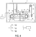
- is an explanatory diagram illustrating, in a front view, a scratch abrasion tester according to another embodiment.
- FIG. 5
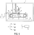
- is an explanatory diagram illustrating, in a front view, a scratch abrasion tester according to yet another embodiment.
- FIG. 6
- is an explanatory diagram illustrating a conveyor belt line in a simplified manner.
- FIG. 7
- is a cross-sectional view taken along B-B of
FIG. 6 . - Below, a scratch abrasion tester and testing method according to embodiments of the present invention will be described on the basis of embodiments illustrated in the drawings.
- As illustrated in
FIGS. 6 and 7 , in a functioning conveyor belt line, objects to be conveyed S is conveyed by aconveyor belt 18, fed onto aconveyor belt 12, and conveyed to a conveying destination by theconveyor belt 12. The objects to be conveyed S may be fed onto theconveyor belt 12 by a hopper and the like. Theconveyor belt 12 is stretched at a prescribed tension betweenpulleys - The
conveyor belt 12 includes acore layer 13 including a core made of canvas, steel cord, or the like, and anupper cover rubber 14 and alower cover rubber 15 that sandwich thecore layer 13 therebetween. Thecore layer 13 is the member that bears the tension that causes theconveyor belt 12 to be stretched. Thelower cover rubber 15 is supported bysupport rollers 17 on a carrier side of theconveyor belt 12, and theupper cover rubber 14 is supported bysupport rollers 17 on a return side of theconveyor belt 12. Threesupport rollers 17 are arranged on the carrier side of theconveyor belt 12 in the belt width direction. Theconveyor belt 12 is supported by thesupport rollers 17 in a recessed manner at a prescribed trough angle a. When thepulley 16a on a drive side is rotationally driven, theconveyor belt 12 runs in one direction at a prescribed running speed V. The objects to be conveyed S are fed onto theupper cover rubber 14, and are loaded on theupper cover rubber 14 and conveyed. - A scratch abrasion tester 1 (hereinafter referred to as tester 1) according to an embodiment of the present invention illustrated in
FIGS. 1 and2 includes a pair ofpulleys contact member 4, anarm portion 3 to which thecontact member 4 is removably attached, ananchor member 5 removably attached to thearm portion 3, and acontrol unit 6a. In the present embodiment, thetester 1 further includes ashape sensor 9a, acalculation unit 11, asupport portion 17a, aload sensor 9b, atemperature sensor 9c, aheating plate 10a, and acasing 10 in which the components described above except for thecontrol unit 6a and thecalculation unit 11 are disposed. - The
heating plate 10a is wider than a rubber sample R and can heat the rubber sample R to a desired temperature and maintain the rubber sample R at this temperature. In embodiments, when a configuration is provided in which thecasing 10 functions, as a thermostatic chamber for maintaining the interior thereof at a desired temperature to set the rubber sample R to the desired temperature, theheating plate 10a can be omitted. In other embodiments, in addition to temperature, the interior of thecasing 10 can be set to and maintained at a desired humidity. - The
pulleys base 2a. At least one of thepulleys pulleys pulley 7a is driven in rotation by adrive motor 6. Thepulley 7b freely rotates. The rotational speed of thepulley 7a is variable and can be set to a desired speed. The rotational speed is controlled by thecontrol unit 6a. Thepulley 7a and thedrive motor 6 can have a configuration in which driving force is transferred via a transferring mechanism including a gear or a belt. - An annular belt member B is stretched between the
pulleys like support portion 17a is disposed between thepulleys support portion 17a is an optional member that may be provided as necessary. - The
arm portion 3 is supported on apost 2b disposed in an upright manner on thebase 2a by arotation shaft 3b, allowing for pivotal movement in the vertical direction. Apin 5c is provided on thearm portion 3 at a first end portion in the longitudinal direction. Thepin 5c and theanchor member 5 are connected by awire 5a that runs through apulley 5b. Thearm portion 3, thewire 5a, and thepulley 5b constitute a pressing mechanism described below that presses thecontact member 4 against the surface of the rubber sample R. - The
contact member 4 is attached to thearm portion 3 in a manner allowing thecontact member 4 to be brought into contact with the surface of the rubber sample R. Specifically, thecontact member 4 is removably attached to a holdingportion 3a fixed to thearm portion 3 at a second end portion in the longitudinal direction. - Various types of
contact members 4 are provided with different specifications (shape, hardness, material, and the like) for the tip that comes into contact with the surface of the rubber sample R. In other words, the contact members 4 (4a, 4b, 4c) have a contact surface with specifications similar to that of the objects to be conveyed S that are conveyed by theconveyor belt 12 that includes theupper cover rubber 14 with similar specifications to the rubber sample R. - For example, the sharpness, hardness, and the like of the objects to be conveyed S varies depending on the type of objects, such as iron ore or other fragmented rocks. Therefore, various types of
contact members 4 having contact surfaces imitating these types of objects are provided. The desiredcontact member 4 can be selected from the various types of contact members 4 (4a, 4b, 4c) and attached to the holdingportion 3a. - The
anchor member 5 is removably attached to one end portion of thewire 5a. The number and types of the attachedanchor member 5 can be changed as appropriate. The load of theanchor member 5 lifts up thepin 5c connected to thewire 5a, and thearm portion 3 pivots in the vertical direction about therotation shaft 3b located partway along thearm portion 3 in the longitudinal direction. This action presses thecontact member 4 against the surface of the rubber sample R. In such a manner, thearm portion 3, thewire 5a, and thepulley 5b constitute the pressing mechanism, however, any pressing mechanism can be used that presses thecontact member 4 against the surface of the rubber sample R. In the present embodiment, the distances of thepressing member 4 and thepin 5c from therotation shaft 3b are changed, so that the pressure at which thecontact member 4 presses against the rubber sample R can be adjusted. - The
anchor member 5 may be any member that can change the pressing load of thecontact member 4 against the rubber sample R. In other words, depending on the weight of theanchor member 5, the pressure at which thecontact member 4 presses against the surface of the rubber sample R can be changed. - The
shape sensor 9a is attached to thecasing 10, for example, and detects the cross-sectional shape of the surface of the rubber sample R. The detection data from theshape sensor 9a is inputted into thecalculation unit 11. Various sensors can be used for theshape sensor 9a, examples of which include a sensor that detects distance by detecting laser light irradiating the surface of the rubber sample R. - The
load sensor 9b is attached to a lower surface at the second end portion in the longitudinal direction of thearm portion 3. Theload sensor 9b successively detects the pressing load acting on thecontact member 4 and the load in the running direction of the annular belt member B stretched between thepulleys contact member 4. In other words, theload sensor 9b successively detects the load in the vertical direction and the horizontal direction acting on thecontact member 4 pressing against the belt member B (rubber sample R). - The
temperature sensor 9c successively detects the surface temperature of the rubber sample R. The detection data from theload sensor 9b and thetemperature sensor 9c is inputted into thecontrol unit 6a. - Next, a testing method for evaluating the scratch abrasion resistance of the rubber sample R using the
tester 1 will be described. - The rubber sample R, which is the evaluation object, is fixed to the outer surface of the annular belt member B stretched between the
pulleys drive motor 6 is driven in rotation. Here, the distance between thepulleys anchor member 5 is manipulated to set the pressing load of thecontact member 4 against the surface of the rubber sample R applied by the pressing mechanism to the desired pressing load. - The desired
contact member 4 is selected from the various types of contact members 4 (4a, 4b, 4c) and attached to the holdingportion 3a. Then, the desiredcontact member 4 is pressed against the surface of the rubber sample R and the cross-sectional shape of the surface of the rubber sample R is detected by theshape sensor 9a. In the present embodiment, thecontact member 4 presses against the surface of the rubber sample R at a position directly above thesupport portion 17a. The rubber sample R continuously runs with thecontact member 4 being pressed thereagainst at a prescribed pressing load. The pointed tips of thecontact member 4 scratch the surface of the rubber sample R causing abrasion in a line-like pattern. - According to an embodiment of the present invention, the rubber sample R, which is the evaluation object, can be evaluated under similar conditions to that of actual usage conditions of the
conveyor belt 12. In other words, the running speed of the annular belt member B (rubber sample R) stretched between thepulleys conveyor belt 12 and the feed objects to be conveyed S, that is, the difference between the speed in the horizontal direction of the objects to be conveyed S when they are feed on theconveyor belt 12 and the running speed in the horizontal direction of theconveyor belt 12. The pressing load from thecontact member 4 is set to equivalent conditions as the pressing load theconveyor belt 12 receives from the objects to be conveyed S, taking into account the amount fed per unit time, the feeding height, and the like. - Additionally, because the annular belt member B is used, the conditions can be very similar to that of the actual usage environment of the
conveyor belt 12. Thus, the scratch abrasion resistance of the upper cover rubber 14 (rubber sample R) of theconveyor belt 12 when actually used can be accurately estimated. The effects of tension on the scratch abrasion resistance of the rubber sample R can also be determined. - In the present embodiment, the
calculation unit 11 calculate the scratch abrasion of the rubber sample R on the basis of the detection data from theshape sensor 9a. Specifically, as illustrated inFIG. 3 , by finding the vertical variation H between a surface R1 of the previous detection and a surface R2 of the current detection and integrating the obtained values over a section in the width direction of the rubber sample R, the amount of scratch abrasion (area of the hatched portion) of the rubber sample R at the cross section for data detection can be obtained. By performing this calculation for the entire rubber sample R in the longitudinal direction, the amount of scratch abrasion for the entire rubber sample R can be calculated. Alternatively, the amount of scratch abrasion per unit length of the rubber sample R is calculated. In such a manner, the amount of scratch abrasion of the rubber sample R can be quickly determined for a certain period and a certain position (range). - Conventionally, to determine the amount of abrasion of the rubber sample R, the weights of the rubber sample R before and after the rubber sample R is scratched by the
contact member 4 are measured, and the amount of abrasion is obtained from the difference between the measured weights. In such cases, the rubber sample R has to be removed from the pair ofpulleys pulleys tester 1, the amount of scratch abrasion of the rubber sample R can be determined without removing the rubber sample R from the pair ofpulleys 7a. Thus, the workability is significantly improved. - In the present embodiment, the
pulleys pulleys pulleys pulleys pulleys shape sensor 9a, the man-hours are reduced. - A configuration in which the belt member B and the rubber sample R are not adhered together and can be freely separated is advantageous because the belt member B can be repeatedly used just by replacing only the used rubber sample R. Additionally, when the amount of scratch abrasion of the rubber sample R is determined, severing the rubber sample R in the belt width direction at a position partway in the longitudinal direction allows only the rubber sample R to be easily removed from the pair of
pulleys shape sensor 9a to reduce the required amount of man-hours. - By providing the
support portion 17a that supports the inner surface of the belt member B between thepulleys contact member 4 can be pressed against the surface of the rubber sample R at a position where the belt member B is supported by thesupport portion 17a and a position where the belt member B is not supported. This allows the difference in the scratch abrasion resistance (amount of abrasion, state of abrasion, and the like) of the rubber sample R at two positions to be determined. Accordingly, the scratch abrasion resistance of the upper cover rubber 14 (rubber sample R) of theconveyor belt 12 when actually used can be further accurately estimated. - Additionally, in the present embodiment, the pressing load acting on the contact member 4 (load in the vertical direction) and the load in the running direction of the rubber sample R (load in the horizontal direction) are successively detected. As a result, the kinetic friction coefficient of the rubber sample R can be determined on the basis of the detection data.
- Furthermore, in the present embodiment, the external environmental temperature of the rubber sample R can be set to a desired temperature. This allows the evaluation to be performed under conditions even more similar to that of the actual usage environment of the
conveyor belt 12. Additionally, by performing evaluation differing the external environmental temperature and the temperature of the rubber sample R, the temperature dependency of the scratch abrasion resistance of the rubber sample R can be determined. - By providing the
temperature sensor 9c, the change in surface temperature of the rubber sample R during evaluation can be measured. When the rubber sample R is subject to abrasion, thermal energy is produced, thus the results of the temperature measurement by thetemperature sensor 9c can be used to determine the energy produced when abrasion occurs. Because the amount of energy differs depending on the type of rubber used, the temperature measurement results are helpful in selecting the type of rubber that can minimize the energy produced, for example. - In an
abrasion tester 1 of another embodiment illustrated inFIG. 4 , thesupport portion 17a supporting the inner surface of the annular belt member B between thepulleys support portion 17a can be a support roller as in the present embodiment instead of a flat plate-like support portion. The span in which thesupport portion 17a can move (the support length of the belt member B which is pressed by the contact member 4) can be changed. Accordingly, by pressing thecontact member 4 against the surface of the rubber sample R and performing measurement with thesupport portion 17a at a position so that the belt member B is not supported, the effect of the span on the scratch abrasion resistance can be determined. - Additionally, the mechanism that enables the
support portion 17a to move is not particularly limited. The mechanism may enable movement with or without gradations. Examples of a mechanism that enables thesupport portion 17a to move include disposing rails on thebase 2a to enable thesupport portion 17a to slide on the rail. - In an
abrasion tester 1 according to another embodiment illustrated inFIG. 5 , the pressing mechanism which presses thecontact member 4 against the surface of the rubber sample R is different than that of the previously described embodiment. In other respects, the basic configuration is the same as that of the previously described embodiment. - The pressing mechanism according to the present embodiment includes a plurality of
anchor members 5 placed on thecontact member 4. Specifically, the pressing mechanism includes abase 3d to which the holdingportion 3a mounted on the upper end portion of thecontact member 4 is attached, a supportingcolumn 3e disposed in an upright manner on thebase 3d, and the plurality ofanchor members 5 through which the supportingcolumn 3e passes through. Theanchor members 5 are placed on thebase 3d in a layered manner. Thebase 3d is supported by another member so that it does not move out of position in the horizontal direction. - In the present embodiment, essentially the total weight of the
base 3d, the supportingcolumn 3e, and theanchor members 5 acts on the surface of the rubber sample R via thecontact member 4. Accordingly, the pressure against the surface of the rubber sample R can be changed by changing the number of theanchor members 5 and the weight of each of theanchor members 5. - Additionally, essentially the pressing mechanism acts only as a load in the vertical direction on the
contact member 4 and the rubber sample R. As a result, variation in the load in the horizontal direction acting on thecontact member 4 and the rubber sample R can be significantly reduced. This allows for a highly accurate measurement with minimal noise, which is advantageous because the scratch abrasion resistance and the kinetic friction coefficient of the rubber sample R can be estimated with greater accuracy. - Furthermore, according to this pressing mechanism, essentially a load only in the vertical-downward direction is placed on the rubber sample R, making the rubber sample R less susceptible to movement up or down. As a result, up and down vibration of the rubber sample R caused by the running of the rubber sample R can be effectively suppressed. In this way also, a highly accurate measurement with minimal noise can be performed which is advantageous because the scratch abrasion resistance and the kinetic friction coefficient of the rubber sample R can be estimated with greater accuracy. Additionally, the pressing mechanism can also be simplified.
-
- 1
- Scratch abrasion tester
- 2a
- Base
- 2b
- Post
- 2c
- Moveable platform
- 3
- Arm portion
- 3a
- Holding portion
- 3b
- Rotation shaft
- 3c
- Shaft hole
- 3d
- Base
- 3e
- Supporting column
- 4 (4a, 4b, 4c)
- Contact member
- 5
- Anchor member
- 5a
- Wire
- 5b
- Pulley
- 5c
- Connection member
- 6
- Drive motor
- 6a
- Control unit
- 7a, 7b
- Pulley
- 8
- Support stand
- 9a
- Shape sensor
- 9b
- Load sensor
- 9c
- Temperature sensor
- 10
- Casing (temperature control mechanism)
- 10a
- Heating plate (temperature control mechanism)
- 11
- Calculation unit
- 12
- Conveyor belt
- 13
- Core layer
- 14
- Upper cover rubber
- 15
- Lower cover rubber
- 16a, 16b
- Pulley
- 17
- Support roller
- 17a
- Support portion
- 18
- Other conveyor belt
- B
- Belt member
- R
- Rubber sample
- R1
- Surface of rubber sample of previous detection
- R2
- Surface of rubber sample of current detection
- S
- Objects to be conveyed
Claims (9)
- A scratch abrasion tester, comprising:a pair of pulleys;an annular belt member stretched between the pair of pulleys;a rubber sample fixed to an outer surface of the belt member;
a contact member with pointed tips that are able to come into contact with a surface of the rubber sample;a pressing mechanism that presses the tips of the contact member against the surface of the rubber sample; andan anchor member for changing a pressing load applied by the contact member;a running speed of the rubber sample being variable,
the contact member including a plurality of types of contact members with different tip specifications,
the contact member that presses against the surface of the rubber sample being discretionarily selected from the plurality of types of contact members, and
the selected contact member being pressed against the surface of the rubber sample. - The scratch abrasion tester according to claim 1, further comprisinga shape sensor configured to detect a cross-sectional shape of the surface of the rubber sample, anda calculation unit configured to obtain an amount of scratch abrasion of the rubber sample on the basis of detection data from the shape sensor.
- The scratch abrasion tester according to claim 1 or 2, wherein
a support portion that supports an inner surface of the belt member is disposed between the pair of pulleys to allow the contact member to press against the surface of the rubber sample at a position where the support portion supports the belt member and a position where the belt member is not supported. - The scratch abrasion tester according to any one of claims 1 to 3, further comprising
a load sensor configured to successively detect the pressing load acting on the contact member and a load in a running direction of the rubber sample acting on the contact member. - The scratch abrasion tester according to any one of claims 1 to 4, further comprising
a temperature control mechanism configured to vary an external environment temperature of the rubber sample. - The scratch abrasion tester according to any one of claims 1 to 5, further comprising
a temperature sensor configured to detect a surface temperature of the rubber sample. - A scratch abrasion testing method in which an annular belt member with a rubber sample fixed to an outer surface thereof is stretched between a pair of pulleys and a contact member with pointed tips is pressed against a surface of the rubber sample by a pressing mechanism, the testing method comprising the steps of:for testing,setting a running speed of the rubber sample to a desired speed;setting a pressing load applied by the contact member to a desired pressing load via an anchor member;selecting, as the contact member, a desired contact member from a plurality of types of contact members with different rubber sample surface contacting tip specifications; andpressing the selected contact member against the surface of the rubber sample.
- The scratch abrasion testing method according to claim 7, further comprising the steps of:detecting a cross-sectional shape of the surface of the rubber sample using a shape sensor, andobtaining an amount of scratch abrasion of the rubber sample using a calculation unit on the basis of detection data from the shape sensor.
- The scratch abrasion testing method according to claim 7 or 8, wherein
an inner surface of the belt member is supported by a support portion between the pair of pulleys, and
the contact member is pressed against the surface of the rubber sample at a position where the support portion supports the belt member and a position where the belt member is not supported.
Applications Claiming Priority (2)
| Application Number | Priority Date | Filing Date | Title |
|---|---|---|---|
| JP2015092686A JP5991404B1 (en) | 2015-04-30 | 2015-04-30 | Scratch wear test apparatus and method |
| PCT/JP2016/057531 WO2016174940A1 (en) | 2015-04-30 | 2016-03-10 | Abrasive wear test device and method |
Publications (3)
| Publication Number | Publication Date |
|---|---|
| EP3290903A1 true EP3290903A1 (en) | 2018-03-07 |
| EP3290903A4 EP3290903A4 (en) | 2019-01-02 |
| EP3290903B1 EP3290903B1 (en) | 2019-12-25 |
Family
ID=56920986
Family Applications (1)
| Application Number | Title | Priority Date | Filing Date |
|---|---|---|---|
| EP16786217.6A Active EP3290903B1 (en) | 2015-04-30 | 2016-03-10 | Abrasive wear test device and method |
Country Status (7)
| Country | Link |
|---|---|
| US (2) | US10732084B2 (en) |
| EP (1) | EP3290903B1 (en) |
| JP (1) | JP5991404B1 (en) |
| CN (2) | CN107532982B (en) |
| AU (1) | AU2016253804B2 (en) |
| RU (1) | RU2017134825A (en) |
| WO (1) | WO2016174940A1 (en) |
Families Citing this family (14)
| Publication number | Priority date | Publication date | Assignee | Title |
|---|---|---|---|---|
| CN106769586A (en) * | 2017-02-08 | 2017-05-31 | 西华大学 | A kind of agricultural machinery track wear experimental rig |
| US10620098B2 (en) * | 2017-07-11 | 2020-04-14 | Covestro Llc | Apparatus and methods for testing components under force |
| CN109612861B (en) * | 2018-12-06 | 2021-06-15 | 祝汪林 | Textile fabric wear resistance test machine |
| CN109975148B (en) * | 2019-01-15 | 2024-01-26 | 中信戴卡股份有限公司 | Automatic sand grain wearing and tearing device |
| CN109900553B (en) * | 2019-03-14 | 2021-08-31 | 中铁六局集团呼和浩特铁路建设有限公司 | Building concrete compressive strength test detection device and operation method thereof |
| CN109975129B (en) * | 2019-04-09 | 2022-03-22 | 安徽理工大学 | Movable frame, simulation test system and simulation method thereof |
| CN111044398B (en) * | 2019-11-12 | 2022-03-25 | 浙江耀阳新材料科技有限公司 | A film anti-scratch test equipment |
| CN114313820B (en) * | 2022-01-10 | 2022-08-23 | 江苏沃源包装制品有限公司 | Intelligent tensioning device for conveying speed of film packaging machine |
| CN114486503B (en) * | 2022-04-18 | 2022-06-17 | 同日智能科技(徐州)有限公司 | Conveyer belt manufacturing performance detection device and detection method |
| CN115372167B (en) * | 2022-09-06 | 2025-01-28 | 临沂鲁驰新材料科技有限公司 | Detection device and method for rubber conveyor belt quality detection |
| CN115586096B (en) * | 2022-11-08 | 2023-06-09 | 邵东智能制造技术研究院有限公司 | Be used for case and bag abrasion resistance check out test set |
| CN116429621B (en) * | 2023-03-27 | 2023-10-24 | 嘉兴鹏翔包装材料有限公司 | Aluminizer cladding material wearability check out test set |
| CN117169103B (en) * | 2023-09-06 | 2024-03-08 | 中航试金石检测科技(大厂)有限公司 | An ultra-high temperature ceramic material corrosion testing equipment |
| CN117330448B (en) * | 2023-10-26 | 2024-04-02 | 枣庄市天一实业有限公司 | Testing equipment and process for deep-sea hydraulic rubber tube |
Family Cites Families (28)
| Publication number | Priority date | Publication date | Assignee | Title |
|---|---|---|---|---|
| JP3076360B2 (en) * | 1990-08-21 | 2000-08-14 | 株式会社ブリヂストン | Detection method of cutting failure of corded rubber sheet |
| JPH08189885A (en) * | 1995-01-09 | 1996-07-23 | Toray Ind Inc | Cut resistance tester for protective materials |
| US5900531A (en) * | 1997-04-07 | 1999-05-04 | Bridgestone/Firestone, Inc. | Portable universal friction testing machine and method |
| US6321586B1 (en) * | 1999-02-01 | 2001-11-27 | Lockheed Martin Federal Systems, Inc. | Conveyor friction measurement and cleaning system |
| JP2001088922A (en) | 1999-09-20 | 2001-04-03 | Bando Chem Ind Ltd | Wear-resistant conveyor belt |
| KR100368559B1 (en) * | 2000-06-29 | 2003-01-24 | 한국타이어 주식회사 | Testing machine for abrasion of rubber specimen |
| US20050050942A1 (en) * | 2001-09-07 | 2005-03-10 | Schmitt Edward A. | Wear test system |
| JP2004020319A (en) * | 2002-06-14 | 2004-01-22 | Jfe Steel Kk | Conveyor belt wear test equipment |
| JP4343791B2 (en) * | 2004-07-26 | 2009-10-14 | 株式会社ブリヂストン | Vulcanized rubber wear test method |
| CN200989873Y (en) | 2006-09-05 | 2007-12-12 | 上海市机械施工有限公司 | Underground digging and cutting hard alloy attrition testing device |
| CN201004038Y (en) | 2007-02-05 | 2008-01-09 | 华南理工大学 | A kind of rubber abrasion testing equipment |
| JP2010260645A (en) | 2007-08-31 | 2010-11-18 | Bridgestone Corp | Wear state detection device for conveyor belt |
| CN101556238B (en) * | 2009-05-11 | 2011-11-16 | 中国船舶重工集团公司第七二五研究所 | Device and method for testing linear reciprocating sliding friction and abrasion |
| CN101725025B (en) * | 2009-11-20 | 2011-07-20 | 东华大学 | Abrasion tester and abrasion test method of dynamically stretched weaving size film |
| JP5534588B2 (en) | 2010-02-24 | 2014-07-02 | 株式会社ブリヂストン | Tire rubber index calculation method, apparatus and program |
| JP5327132B2 (en) * | 2010-04-27 | 2013-10-30 | 三菱電機株式会社 | Wear test apparatus and wear test method |
| JP5486412B2 (en) * | 2010-06-07 | 2014-05-07 | 横浜ゴム株式会社 | Evaluation system and method for impact resistance of conveyor belts |
| CN102004060B (en) * | 2010-09-10 | 2013-06-12 | 杭州中策橡胶有限公司 | Test method and device for measuring sharp object puncture resistance of rubber material |
| JP2012202811A (en) * | 2011-03-25 | 2012-10-22 | Meiji Rubber & Chem Co Ltd | Abrasion testing method of rubber material or the like and abrasion testing device used therefor |
| JP2012202926A (en) * | 2011-03-28 | 2012-10-22 | Bridgestone Corp | Wear testing apparatus |
| JP5834486B2 (en) * | 2011-05-18 | 2015-12-24 | 横浜ゴム株式会社 | Conveyor belt evaluation apparatus and evaluation method |
| CN102854075B (en) * | 2011-06-28 | 2016-03-09 | 东莞劲胜精密组件股份有限公司 | The method of testing of the resistance to artificial pawl wear hardness of a kind of coating |
| CN202362219U (en) * | 2011-11-24 | 2012-08-01 | 成都市新筑路桥机械股份有限公司 | Device for testing abrasion performance of rubber track shoe |
| CN102384881B (en) * | 2011-11-24 | 2013-02-13 | 成都市新筑路桥机械股份有限公司 | Testing device for rubber creeper tread abrasion loss performance and method |
| CN202433272U (en) * | 2011-12-27 | 2012-09-12 | 江门市本和机车配件实业有限公司 | Friction and wear tester for high temperature surface of metal-rubber composite sealing plate |
| JP6002462B2 (en) * | 2012-06-15 | 2016-10-05 | 横浜ゴム株式会社 | Method and apparatus for measuring resistance force of conveyor belt over a support roller |
| JP5915456B2 (en) * | 2012-08-23 | 2016-05-11 | 横浜ゴム株式会社 | Conveyor belt |
| CN104502215B (en) * | 2015-01-08 | 2017-05-24 | 攀钢集团研究院有限公司 | Wear test device and wear test method |
-
2015
- 2015-04-30 JP JP2015092686A patent/JP5991404B1/en active Active
-
2016
- 2016-03-10 AU AU2016253804A patent/AU2016253804B2/en not_active Ceased
- 2016-03-10 RU RU2017134825A patent/RU2017134825A/en not_active Application Discontinuation
- 2016-03-10 CN CN201680019732.2A patent/CN107532982B/en active Active
- 2016-03-10 WO PCT/JP2016/057531 patent/WO2016174940A1/en not_active Ceased
- 2016-03-10 CN CN202010860710.7A patent/CN111879646A/en active Pending
- 2016-03-10 EP EP16786217.6A patent/EP3290903B1/en active Active
- 2016-03-10 US US15/570,709 patent/US10732084B2/en not_active Expired - Fee Related
-
2020
- 2020-07-02 US US16/920,354 patent/US11231353B2/en active Active
Also Published As
| Publication number | Publication date |
|---|---|
| RU2017134825A3 (en) | 2019-04-04 |
| US11231353B2 (en) | 2022-01-25 |
| CN111879646A (en) | 2020-11-03 |
| CN107532982A (en) | 2018-01-02 |
| US20180292301A1 (en) | 2018-10-11 |
| US10732084B2 (en) | 2020-08-04 |
| AU2016253804A1 (en) | 2017-10-19 |
| JP5991404B1 (en) | 2016-09-14 |
| CN107532982B (en) | 2020-09-22 |
| US20200333227A1 (en) | 2020-10-22 |
| EP3290903B1 (en) | 2019-12-25 |
| AU2016253804B2 (en) | 2018-09-13 |
| RU2017134825A (en) | 2019-04-04 |
| WO2016174940A1 (en) | 2016-11-03 |
| EP3290903A4 (en) | 2019-01-02 |
| JP2016211869A (en) | 2016-12-15 |
Similar Documents
| Publication | Publication Date | Title |
|---|---|---|
| US11231353B2 (en) | Scratch abrasion tester and testing method | |
| JP6394295B2 (en) | Wear test apparatus and method | |
| US10184857B2 (en) | Impact test device and method | |
| US10371613B2 (en) | Apparatus and method for loading and wear testing a rubber sample | |
| US10928284B2 (en) | Impact test method and device in which an impact application member is caused to fall freely onto and collide with a test sample | |
| AU2017296469B2 (en) | Method for evaluating wear resistance of rubber | |
| AU2013275272B2 (en) | Method for measuring resistance of conveyor belt to getting over support roller, and device therefor | |
| JP2006292736A (en) | Method and apparatus for measuring resistance force of conveyor belt overcoming conveyor roller and evaluation method of power loss of conveyor belt | |
| CN109313111B (en) | Abrasion test device for rubber | |
| KR101238392B1 (en) | Apparatus and method for measuring thickness of taper leaf spring for vehicle | |
| KR20190060261A (en) | Friction tester | |
| JP6314623B2 (en) | Conveyor belt running performance evaluation method | |
| CA2363092A1 (en) | Method and machine for grading timber elements | |
| JP6314622B2 (en) | Conveyor belt running resistance measuring device | |
| PL230283B1 (en) | Device for testing rolling resistance of rollers | |
| PL226352B1 (en) | Test stand for examining the strip contraflexuring resistance |
Legal Events
| Date | Code | Title | Description |
|---|---|---|---|
| STAA | Information on the status of an ep patent application or granted ep patent |
Free format text: STATUS: THE INTERNATIONAL PUBLICATION HAS BEEN MADE |
|
| PUAI | Public reference made under article 153(3) epc to a published international application that has entered the european phase |
Free format text: ORIGINAL CODE: 0009012 |
|
| STAA | Information on the status of an ep patent application or granted ep patent |
Free format text: STATUS: REQUEST FOR EXAMINATION WAS MADE |
|
| 17P | Request for examination filed |
Effective date: 20171017 |
|
| AK | Designated contracting states |
Kind code of ref document: A1 Designated state(s): AL AT BE BG CH CY CZ DE DK EE ES FI FR GB GR HR HU IE IS IT LI LT LU LV MC MK MT NL NO PL PT RO RS SE SI SK SM TR |
|
| AX | Request for extension of the european patent |
Extension state: BA ME |
|
| DAV | Request for validation of the european patent (deleted) | ||
| DAX | Request for extension of the european patent (deleted) | ||
| STAA | Information on the status of an ep patent application or granted ep patent |
Free format text: STATUS: EXAMINATION IS IN PROGRESS |
|
| A4 | Supplementary search report drawn up and despatched |
Effective date: 20181129 |
|
| RIC1 | Information provided on ipc code assigned before grant |
Ipc: G01N 3/56 20060101AFI20181123BHEP |
|
| 17Q | First examination report despatched |
Effective date: 20181210 |
|
| GRAP | Despatch of communication of intention to grant a patent |
Free format text: ORIGINAL CODE: EPIDOSNIGR1 |
|
| STAA | Information on the status of an ep patent application or granted ep patent |
Free format text: STATUS: GRANT OF PATENT IS INTENDED |
|
| INTG | Intention to grant announced |
Effective date: 20190723 |
|
| GRAS | Grant fee paid |
Free format text: ORIGINAL CODE: EPIDOSNIGR3 |
|
| GRAA | (expected) grant |
Free format text: ORIGINAL CODE: 0009210 |
|
| STAA | Information on the status of an ep patent application or granted ep patent |
Free format text: STATUS: THE PATENT HAS BEEN GRANTED |
|
| AK | Designated contracting states |
Kind code of ref document: B1 Designated state(s): AL AT BE BG CH CY CZ DE DK EE ES FI FR GB GR HR HU IE IS IT LI LT LU LV MC MK MT NL NO PL PT RO RS SE SI SK SM TR |
|
| REG | Reference to a national code |
Ref country code: GB Ref legal event code: FG4D |
|
| REG | Reference to a national code |
Ref country code: CH Ref legal event code: EP |
|
| REG | Reference to a national code |
Ref country code: AT Ref legal event code: REF Ref document number: 1217652 Country of ref document: AT Kind code of ref document: T Effective date: 20200115 |
|
| REG | Reference to a national code |
Ref country code: DE Ref legal event code: R096 Ref document number: 602016026962 Country of ref document: DE |
|
| REG | Reference to a national code |
Ref country code: IE Ref legal event code: FG4D |
|
| REG | Reference to a national code |
Ref country code: NL Ref legal event code: MP Effective date: 20191225 |
|
| PG25 | Lapsed in a contracting state [announced via postgrant information from national office to epo] |
Ref country code: BG Free format text: LAPSE BECAUSE OF FAILURE TO SUBMIT A TRANSLATION OF THE DESCRIPTION OR TO PAY THE FEE WITHIN THE PRESCRIBED TIME-LIMIT Effective date: 20200325 Ref country code: GR Free format text: LAPSE BECAUSE OF FAILURE TO SUBMIT A TRANSLATION OF THE DESCRIPTION OR TO PAY THE FEE WITHIN THE PRESCRIBED TIME-LIMIT Effective date: 20200326 Ref country code: NO Free format text: LAPSE BECAUSE OF FAILURE TO SUBMIT A TRANSLATION OF THE DESCRIPTION OR TO PAY THE FEE WITHIN THE PRESCRIBED TIME-LIMIT Effective date: 20200325 Ref country code: FI Free format text: LAPSE BECAUSE OF FAILURE TO SUBMIT A TRANSLATION OF THE DESCRIPTION OR TO PAY THE FEE WITHIN THE PRESCRIBED TIME-LIMIT Effective date: 20191225 Ref country code: LT Free format text: LAPSE BECAUSE OF FAILURE TO SUBMIT A TRANSLATION OF THE DESCRIPTION OR TO PAY THE FEE WITHIN THE PRESCRIBED TIME-LIMIT Effective date: 20191225 Ref country code: SE Free format text: LAPSE BECAUSE OF FAILURE TO SUBMIT A TRANSLATION OF THE DESCRIPTION OR TO PAY THE FEE WITHIN THE PRESCRIBED TIME-LIMIT Effective date: 20191225 Ref country code: LV Free format text: LAPSE BECAUSE OF FAILURE TO SUBMIT A TRANSLATION OF THE DESCRIPTION OR TO PAY THE FEE WITHIN THE PRESCRIBED TIME-LIMIT Effective date: 20191225 |
|
| REG | Reference to a national code |
Ref country code: LT Ref legal event code: MG4D |
|
| PG25 | Lapsed in a contracting state [announced via postgrant information from national office to epo] |
Ref country code: RS Free format text: LAPSE BECAUSE OF FAILURE TO SUBMIT A TRANSLATION OF THE DESCRIPTION OR TO PAY THE FEE WITHIN THE PRESCRIBED TIME-LIMIT Effective date: 20191225 Ref country code: HR Free format text: LAPSE BECAUSE OF FAILURE TO SUBMIT A TRANSLATION OF THE DESCRIPTION OR TO PAY THE FEE WITHIN THE PRESCRIBED TIME-LIMIT Effective date: 20191225 |
|
| PG25 | Lapsed in a contracting state [announced via postgrant information from national office to epo] |
Ref country code: AL Free format text: LAPSE BECAUSE OF FAILURE TO SUBMIT A TRANSLATION OF THE DESCRIPTION OR TO PAY THE FEE WITHIN THE PRESCRIBED TIME-LIMIT Effective date: 20191225 |
|
| PG25 | Lapsed in a contracting state [announced via postgrant information from national office to epo] |
Ref country code: EE Free format text: LAPSE BECAUSE OF FAILURE TO SUBMIT A TRANSLATION OF THE DESCRIPTION OR TO PAY THE FEE WITHIN THE PRESCRIBED TIME-LIMIT Effective date: 20191225 Ref country code: NL Free format text: LAPSE BECAUSE OF FAILURE TO SUBMIT A TRANSLATION OF THE DESCRIPTION OR TO PAY THE FEE WITHIN THE PRESCRIBED TIME-LIMIT Effective date: 20191225 Ref country code: RO Free format text: LAPSE BECAUSE OF FAILURE TO SUBMIT A TRANSLATION OF THE DESCRIPTION OR TO PAY THE FEE WITHIN THE PRESCRIBED TIME-LIMIT Effective date: 20191225 Ref country code: CZ Free format text: LAPSE BECAUSE OF FAILURE TO SUBMIT A TRANSLATION OF THE DESCRIPTION OR TO PAY THE FEE WITHIN THE PRESCRIBED TIME-LIMIT Effective date: 20191225 Ref country code: PT Free format text: LAPSE BECAUSE OF FAILURE TO SUBMIT A TRANSLATION OF THE DESCRIPTION OR TO PAY THE FEE WITHIN THE PRESCRIBED TIME-LIMIT Effective date: 20200520 |
|
| PG25 | Lapsed in a contracting state [announced via postgrant information from national office to epo] |
Ref country code: SK Free format text: LAPSE BECAUSE OF FAILURE TO SUBMIT A TRANSLATION OF THE DESCRIPTION OR TO PAY THE FEE WITHIN THE PRESCRIBED TIME-LIMIT Effective date: 20191225 Ref country code: IS Free format text: LAPSE BECAUSE OF FAILURE TO SUBMIT A TRANSLATION OF THE DESCRIPTION OR TO PAY THE FEE WITHIN THE PRESCRIBED TIME-LIMIT Effective date: 20200425 Ref country code: SM Free format text: LAPSE BECAUSE OF FAILURE TO SUBMIT A TRANSLATION OF THE DESCRIPTION OR TO PAY THE FEE WITHIN THE PRESCRIBED TIME-LIMIT Effective date: 20191225 |
|
| REG | Reference to a national code |
Ref country code: DE Ref legal event code: R097 Ref document number: 602016026962 Country of ref document: DE |
|
| PG25 | Lapsed in a contracting state [announced via postgrant information from national office to epo] |
Ref country code: DK Free format text: LAPSE BECAUSE OF FAILURE TO SUBMIT A TRANSLATION OF THE DESCRIPTION OR TO PAY THE FEE WITHIN THE PRESCRIBED TIME-LIMIT Effective date: 20191225 Ref country code: MC Free format text: LAPSE BECAUSE OF FAILURE TO SUBMIT A TRANSLATION OF THE DESCRIPTION OR TO PAY THE FEE WITHIN THE PRESCRIBED TIME-LIMIT Effective date: 20191225 Ref country code: ES Free format text: LAPSE BECAUSE OF FAILURE TO SUBMIT A TRANSLATION OF THE DESCRIPTION OR TO PAY THE FEE WITHIN THE PRESCRIBED TIME-LIMIT Effective date: 20191225 |
|
| PLBE | No opposition filed within time limit |
Free format text: ORIGINAL CODE: 0009261 |
|
| REG | Reference to a national code |
Ref country code: CH Ref legal event code: PL |
|
| STAA | Information on the status of an ep patent application or granted ep patent |
Free format text: STATUS: NO OPPOSITION FILED WITHIN TIME LIMIT |
|
| REG | Reference to a national code |
Ref country code: AT Ref legal event code: MK05 Ref document number: 1217652 Country of ref document: AT Kind code of ref document: T Effective date: 20191225 |
|
| PG25 | Lapsed in a contracting state [announced via postgrant information from national office to epo] |
Ref country code: SI Free format text: LAPSE BECAUSE OF FAILURE TO SUBMIT A TRANSLATION OF THE DESCRIPTION OR TO PAY THE FEE WITHIN THE PRESCRIBED TIME-LIMIT Effective date: 20191225 |
|
| 26N | No opposition filed |
Effective date: 20200928 |
|
| REG | Reference to a national code |
Ref country code: BE Ref legal event code: MM Effective date: 20200331 |
|
| PG25 | Lapsed in a contracting state [announced via postgrant information from national office to epo] |
Ref country code: LU Free format text: LAPSE BECAUSE OF NON-PAYMENT OF DUE FEES Effective date: 20200310 |
|
| PG25 | Lapsed in a contracting state [announced via postgrant information from national office to epo] |
Ref country code: LI Free format text: LAPSE BECAUSE OF NON-PAYMENT OF DUE FEES Effective date: 20200331 Ref country code: FR Free format text: LAPSE BECAUSE OF NON-PAYMENT OF DUE FEES Effective date: 20200331 Ref country code: IE Free format text: LAPSE BECAUSE OF NON-PAYMENT OF DUE FEES Effective date: 20200310 Ref country code: IT Free format text: LAPSE BECAUSE OF FAILURE TO SUBMIT A TRANSLATION OF THE DESCRIPTION OR TO PAY THE FEE WITHIN THE PRESCRIBED TIME-LIMIT Effective date: 20191225 Ref country code: CH Free format text: LAPSE BECAUSE OF NON-PAYMENT OF DUE FEES Effective date: 20200331 Ref country code: AT Free format text: LAPSE BECAUSE OF FAILURE TO SUBMIT A TRANSLATION OF THE DESCRIPTION OR TO PAY THE FEE WITHIN THE PRESCRIBED TIME-LIMIT Effective date: 20191225 |
|
| PG25 | Lapsed in a contracting state [announced via postgrant information from national office to epo] |
Ref country code: BE Free format text: LAPSE BECAUSE OF NON-PAYMENT OF DUE FEES Effective date: 20200331 Ref country code: PL Free format text: LAPSE BECAUSE OF FAILURE TO SUBMIT A TRANSLATION OF THE DESCRIPTION OR TO PAY THE FEE WITHIN THE PRESCRIBED TIME-LIMIT Effective date: 20191225 |
|
| GBPC | Gb: european patent ceased through non-payment of renewal fee |
Effective date: 20200325 |
|
| PG25 | Lapsed in a contracting state [announced via postgrant information from national office to epo] |
Ref country code: GB Free format text: LAPSE BECAUSE OF NON-PAYMENT OF DUE FEES Effective date: 20200325 |
|
| PG25 | Lapsed in a contracting state [announced via postgrant information from national office to epo] |
Ref country code: TR Free format text: LAPSE BECAUSE OF FAILURE TO SUBMIT A TRANSLATION OF THE DESCRIPTION OR TO PAY THE FEE WITHIN THE PRESCRIBED TIME-LIMIT Effective date: 20191225 Ref country code: MT Free format text: LAPSE BECAUSE OF FAILURE TO SUBMIT A TRANSLATION OF THE DESCRIPTION OR TO PAY THE FEE WITHIN THE PRESCRIBED TIME-LIMIT Effective date: 20191225 Ref country code: CY Free format text: LAPSE BECAUSE OF FAILURE TO SUBMIT A TRANSLATION OF THE DESCRIPTION OR TO PAY THE FEE WITHIN THE PRESCRIBED TIME-LIMIT Effective date: 20191225 |
|
| PG25 | Lapsed in a contracting state [announced via postgrant information from national office to epo] |
Ref country code: MK Free format text: LAPSE BECAUSE OF FAILURE TO SUBMIT A TRANSLATION OF THE DESCRIPTION OR TO PAY THE FEE WITHIN THE PRESCRIBED TIME-LIMIT Effective date: 20191225 |
|
| P01 | Opt-out of the competence of the unified patent court (upc) registered |
Effective date: 20230512 |
|
| PGFP | Annual fee paid to national office [announced via postgrant information from national office to epo] |
Ref country code: DE Payment date: 20260128 Year of fee payment: 11 |