EP3290889A2 - System und methode zur kalibration einer einrichtung - Google Patents
System und methode zur kalibration einer einrichtung Download PDFInfo
- Publication number
- EP3290889A2 EP3290889A2 EP17184501.9A EP17184501A EP3290889A2 EP 3290889 A2 EP3290889 A2 EP 3290889A2 EP 17184501 A EP17184501 A EP 17184501A EP 3290889 A2 EP3290889 A2 EP 3290889A2
- Authority
- EP
- European Patent Office
- Prior art keywords
- torque
- tool
- drive shaft
- prevailing
- transducer
- Prior art date
- Legal status (The legal status is an assumption and is not a legal conclusion. Google has not performed a legal analysis and makes no representation as to the accuracy of the status listed.)
- Withdrawn
Links
Images


Classifications
-
- G—PHYSICS
- G01—MEASURING; TESTING
- G01L—MEASURING FORCE, STRESS, TORQUE, WORK, MECHANICAL POWER, MECHANICAL EFFICIENCY, OR FLUID PRESSURE
- G01L25/00—Testing or calibrating of apparatus for measuring force, torque, work, mechanical power, or mechanical efficiency
- G01L25/003—Testing or calibrating of apparatus for measuring force, torque, work, mechanical power, or mechanical efficiency for measuring torque
-
- B—PERFORMING OPERATIONS; TRANSPORTING
- B25—HAND TOOLS; PORTABLE POWER-DRIVEN TOOLS; MANIPULATORS
- B25B—TOOLS OR BENCH DEVICES NOT OTHERWISE PROVIDED FOR, FOR FASTENING, CONNECTING, DISENGAGING, OR HOLDING
- B25B23/00—Details of, or accessories for, spanners, wrenches, screwdrivers
- B25B23/14—Arrangement of torque limiters or torque indicators in wrenches or screwdrivers
- B25B23/142—Arrangement of torque limiters or torque indicators in wrenches or screwdrivers specially adapted for hand operated wrenches or screwdrivers
- B25B23/1422—Arrangement of torque limiters or torque indicators in wrenches or screwdrivers specially adapted for hand operated wrenches or screwdrivers torque indicators or adjustable torque limiters
- B25B23/1425—Arrangement of torque limiters or torque indicators in wrenches or screwdrivers specially adapted for hand operated wrenches or screwdrivers torque indicators or adjustable torque limiters by electrical means
-
- F—MECHANICAL ENGINEERING; LIGHTING; HEATING; WEAPONS; BLASTING
- F04—POSITIVE - DISPLACEMENT MACHINES FOR LIQUIDS; PUMPS FOR LIQUIDS OR ELASTIC FLUIDS
- F04D—NON-POSITIVE-DISPLACEMENT PUMPS
- F04D29/00—Details, component parts, or accessories
- F04D29/04—Shafts or bearings, or assemblies thereof
- F04D29/042—Axially shiftable rotors
-
- G—PHYSICS
- G06—COMPUTING OR CALCULATING; COUNTING
- G06F—ELECTRIC DIGITAL DATA PROCESSING
- G06F3/00—Input arrangements for transferring data to be processed into a form capable of being handled by the computer; Output arrangements for transferring data from processing unit to output unit, e.g. interface arrangements
- G06F3/01—Input arrangements or combined input and output arrangements for interaction between user and computer
- G06F3/018—Input/output arrangements for oriental characters
Definitions
- the present invention relates to tools, in particular to tools such as torque wrenches.
- a calibration system includes a housing and a drive shaft within the housing.
- the drive shaft extends to a connection point on a wall of the housing.
- the calibration system includes a load application apparatus operatively connected to the drive shaft to apply a force to the drive shaft.
- the calibration system includes a plurality of housing transducers operatively connected to the drive shaft to measure at least one of an in-line torque or a prevailing torque of the drive shaft.
- the calibration system includes a processing unit operatively connected to at least one of the plurality of housing transducers to provide a pass/fail output.
- the pass/fail output can be based on a comparison between the prevailing torque measurement from at least one of the housing transducers and a prevailing torque measurement from an external tool.
- the calibration system includes a selectively removable tool operatively connected to the connection point on the wall of the housing to apply a torque to the drive shaft.
- the selectively removable tool can include a tool transducer to determine at least one of an in-line torque and a prevailing torque being applied to the drive shaft by the selectively removable tool.
- the tool transducer can be operatively connected to a processing unit that is operatively connected to at least one of the plurality of housing transducers.
- the processing unit can provide a pass/fail output based on a comparison between the prevailing torque measurement from at least one of the plurality of housing transducers and the prevailing torque measurement from the tool transducer.
- a method for calibrating a tool includes applying a torque to a drive shaft within a test-cart housing with a load application apparatus.
- the method includes connecting a selectively removable tool to the drive shaft through a connection point on a wall of the test-cart housing to apply a torque to the drive shaft, and determining the prevailing torque being applied to the drive shaft by the selectively removable tool with a tool transducer operatively connected to the selectively removable tool.
- the method includes determining the prevailing torque being applied to the drive shaft by the load application apparatus with a test transducer operatively connected to the drive shaft.
- the method includes comparing the prevailing torque being applied by the selectively removable tool to the prevailing torque being applied by the load application apparatus using a processing unit operatively connected to at least one of the test transducer or the tool transducer to determine a variance between the prevailing torque being applied by the selectively removable tool and the prevailing torque being applied by the load application apparatus.
- the method includes generating at least one of a pass or fail output from the processing unit based on whether the variance is within a predetermined variance threshold. It is contemplated that in some embodiments, the method can include calibrating the selectively removable tool if a fail output is generated.
- a method for measuring prevailing torque in a tool includes applying torque using a tool until a trigger torque threshold value is met in a torque transducer, and measuring torque data recorded by the torque transducer until the trigger torque threshold value is met.
- the method includes evaluating torque data recorded by the torque transducer during applying the torque prior to the trigger torque threshold value to determine a prevailing torque value, and determining whether the prevailing torque value is within a predetermined prevailing torque range.
- the method includes signaling at least one of pass or fail depending on whether the prevailing torque is within the prevailing torque range.
- the method includes adjusting a shut-off threshold torque based on the prevailing torque.
- the method can include shutting off the tool if fail is signaled.
- the method can include applying additional torque using the tool until the shut-off threshold torque is met if pass is signaled.
- the method includes adjusting at least one of a minimum shut-off torque or a maximum shut-off torque. Evaluating the torque data recorded by the torque transducer during applying the torque can include evaluating the torque data over a predetermined torque evaluation angle range.
- FIG. 1 a schematic depiction of an exemplary embodiment of a calibration system constructed in accordance with the disclosure is shown in Fig. 1 and is designated generally by reference character 100.
- Figures 2-4 Other embodiments of calibration systems, methods for calibrating a tool, and/or methods for measuring prevailing torque in a tool in accordance with the disclosure, or aspects thereof, are provided in Figures 2-4 , as will be described.
- a calibration system 100 includes a housing 102 and a drive shaft 104 within housing 102.
- Calibration system 100 is a dynamic calibration system.
- Drive shaft 104 extends to a connection point 106 on a wall 108 of housing 102.
- Calibration system 100 includes a load application apparatus 110 operatively connected to drive shaft 104 to apply a force to drive shaft 104, e.g. a rotational force.
- Calibration system 100 includes a plurality of housing transducers 112 and 114 operatively connected to drive shaft 104 to measure at least one of an in-line torque or a prevailing torque of drive shaft 104.
- calibration system 100 includes a processing unit 116 operatively connected to at least one of housing transducers 112 and 114 to provide a pass or fail output.
- Transducers 112 and 114 can be wirelessly connected, hard-wired, or the like to processing unit 116 and/or drive shaft 104.
- the pass or fail output is based on a comparison between the prevailing torque measurement from at least one of housing transducers 112 and 114 and a prevailing torque measurement from an external tool 118.
- calibration system 100 includes a selectively removable tool 118 operatively connected to connection point 106 on wall 108 of housing 102 to apply a torque to drive shaft 104.
- Selectively removable tool 118 can be an automatic torque wrench or the like.
- selectively removable tool 118 includes a tool transducer 120 to determine at least one of an in-line torque and a prevailing torque being applied to drive shaft 104 by selectively removable tool 118.
- Tool transducer 120 is operatively connected to processing unit 116.
- Tool transducer 120 can be wirelessly connected, hard-wired, or the like, to processing unit 116.
- Processing unit 116 provides one of a pass or fail output based on a comparison between the prevailing torque measurement from at least one of housing transducers 112 and 114 and the prevailing torque measurement from tool transducer 120.
- a method 200 for calibrating a tool includes applying a torque to a drive shaft, e.g. drive shaft 104, within a test-cart housing, e.g. housing 102, with a load application apparatus, e.g. load application apparatus 110, indicated schematically by box 202.
- Method 200 includes connecting the tool to the drive shaft through a connection point, e.g. connection point 106, on a wall of the test-cart housing to apply a torque to the drive shaft, indicated schematically by box 204.
- Method 200 includes determining the prevailing torque being applied to the drive shaft by the tool with a tool transducer, e.g.
- Method includes determining the prevailing torque being applied to the drive shaft by the load application apparatus with a test transducer, e.g. one of housing transducers 112 and 114, operatively connected to the drive shaft, indicated schematically by box 208.
- Prevailing torque being applied to the drive shaft determined with either the test transducer or the tool transducer can be determined using method 300, described below.
- method 200 includes comparing the prevailing torque being applied to the drive shaft by the selectively removable tool to the prevailing torque being applied to the drive shaft by the load application apparatus using a processing unit, e.g. processing unit 116, operatively connected to at least one of the test transducer or the tool transducer to determine a variance between the prevailing torque being applied by the selectively removable tool and the prevailing torque being applied by the load application apparatus, indicated schematically by box 210.
- Method 200 includes generating at least one of a pass or fail output from the processing unit based on whether the variance is within a predetermined variance threshold, indicated schematically by box 212.
- the predetermined variance threshold is a predetermined value stored in a database and selected based on the characteristics of pieces being joined together, e.g. the stack-up.
- the input of the predetermined variance threshold is indicated schematically by box 211.
- Method 200 includes calibrating the selectively removable tool if a fail output is generated, indicated schematically by box 214.
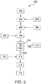
- a method 300 for measuring prevailing torque in a tool includes applying torque to a fastener, for example, using the tool until a trigger torque threshold value is met in a torque transducer, e.g. tool transducer 120, indicated schematically by box 302.
- Method 300 includes measuring torque data recorded by the torque transducer until the trigger torque threshold value is met, indicated schematically by box 304.
- the trigger torque threshold value is a predetermined value stored in a database and selected based on the stack-up.
- the input of the trigger torque threshold is indicated schematically by box 303.
- Method 300 includes evaluating torque data recorded by the torque transducer during applying the torque prior to meeting the trigger torque threshold value to determine a prevailing torque value, indicated schematically by box 306.
- Evaluating the torque data recorded by the torque transducer during applying the torque includes evaluating the torque data over a predetermined prevailing torque evaluation angle range.
- the prevailing torque evaluation angle range is a predetermined value stored in a database and selected based on the stack-up.
- the input of the predetermined prevailing torque evaluation angle range is indicated schematically by box 305.
- This input also includes a predetermined angle offset, e.g. the amount of angle to look back from the trigger torque threshold value to get to the top end of the predetermined prevailing torque evaluation angle range, as shown in more detail in Fig. 4 .
- This predetermined angle offset can also be based on the characteristics of the stack up.
- method 300 includes determining whether the prevailing torque value is within a predetermined prevailing torque range, indicated schematically by box 308.
- the prevailing torque range is a predetermined value stored in a database and selected based on the stack-up.
- the input of the prevailing torque range is indicated schematically by box 309.
- Method 300 includes signaling at least one of "pass” or “fail” depending on whether the prevailing torque is within the prevailing torque range, indicated schematically by box 310. If “fail” is signaled, method 300 includes shutting off the tool, indicated schematically by box 312. If “pass” is signaled, method 300 includes applying additional torque using the tool until a shut-off threshold is met, indicated schematically by box 314.
- the shut-off threshold is a predetermined value stored in a database and selected based on the stack-up.
- the input of the shut-off threshold is indicated schematically by box 313.
- Method 300 includes adjusting the shut-off threshold based on the prevailing torque, indicated schematically by box 316.
- Method 300 includes adjusting minimum and maximum shut-off torques based on the prevailing torque, indicated schematically by 318.
- Method 300 provides a more consistent prevailing torque measurement to be used in compensating for the shut-off threshold, as compared with traditional systems that use angle rotation data to identify prevailing torque data, as the angle rotation data is not always repeatable and thus can result in different readings.
- Method 300 can be used to determine the prevailing torque being applied to the drive shaft, as described above with respect to boxes 206 and/or 208.
- a plot of torque versus angle 400 recorded by a transducer shows the predetermined prevailing torque evaluation angle range 402.
- Minimum and maximum prevailing torques 406 and 408, respectively, represent the low and high ends of a prevailing torque range 410.
- Trigger torque 404 typically occurs when the parts, e.g. fastener and stack-up, begin to compress together.
- a predetermined angle offset 418 is the amount of angle to look back from trigger torque 404 to get to the top end of predetermined prevailing torque evaluation angle range 402.
- a shut-off threshold 412 is represented by a point in between a minimum shut-off torque 414 and a maximum shut-off torque 416.
- Minimum and maximum shut-off torques 414 and 416, respectively, are predetermined depending on the stack-up and can be adjusted as needed based on the prevailing torque measurement and/or shut-off threshold 412.
Landscapes
- Engineering & Computer Science (AREA)
- General Engineering & Computer Science (AREA)
- Physics & Mathematics (AREA)
- General Physics & Mathematics (AREA)
- Theoretical Computer Science (AREA)
- Mechanical Engineering (AREA)
- Human Computer Interaction (AREA)
- Details Of Spanners, Wrenches, And Screw Drivers And Accessories (AREA)
- Force Measurement Appropriate To Specific Purposes (AREA)
- Numerical Control (AREA)
Priority Applications (1)
| Application Number | Priority Date | Filing Date | Title |
|---|---|---|---|
| EP20196249.5A EP3770573A1 (de) | 2016-08-09 | 2017-08-02 | System und methode zur kalibration einer einrichtung |
Applications Claiming Priority (1)
| Application Number | Priority Date | Filing Date | Title |
|---|---|---|---|
| US201662372568P | 2016-08-09 | 2016-08-09 |
Related Child Applications (1)
| Application Number | Title | Priority Date | Filing Date |
|---|---|---|---|
| EP20196249.5A Division EP3770573A1 (de) | 2016-08-09 | 2017-08-02 | System und methode zur kalibration einer einrichtung |
Publications (2)
| Publication Number | Publication Date |
|---|---|
| EP3290889A2 true EP3290889A2 (de) | 2018-03-07 |
| EP3290889A3 EP3290889A3 (de) | 2018-05-30 |
Family
ID=59738111
Family Applications (2)
| Application Number | Title | Priority Date | Filing Date |
|---|---|---|---|
| EP20196249.5A Withdrawn EP3770573A1 (de) | 2016-08-09 | 2017-08-02 | System und methode zur kalibration einer einrichtung |
| EP17184501.9A Withdrawn EP3290889A3 (de) | 2016-08-09 | 2017-08-02 | System und methode zur kalibration einer einrichtung |
Family Applications Before (1)
| Application Number | Title | Priority Date | Filing Date |
|---|---|---|---|
| EP20196249.5A Withdrawn EP3770573A1 (de) | 2016-08-09 | 2017-08-02 | System und methode zur kalibration einer einrichtung |
Country Status (2)
| Country | Link |
|---|---|
| US (2) | US10365177B2 (de) |
| EP (2) | EP3770573A1 (de) |
Families Citing this family (6)
| Publication number | Priority date | Publication date | Assignee | Title |
|---|---|---|---|---|
| SE538622C2 (sv) * | 2015-04-02 | 2016-10-04 | Atlas Copco Ind Technique Ab | Power tool with output torque compensation and method therefore |
| EP3770573A1 (de) * | 2016-08-09 | 2021-01-27 | Hamilton Sundstrand Corporation | System und methode zur kalibration einer einrichtung |
| US11752604B2 (en) * | 2018-04-13 | 2023-09-12 | Snap-On Incorporated | System and method for measuring torque and angle |
| US11486786B2 (en) * | 2018-11-26 | 2022-11-01 | Gary Childers | Torque testing and calibration system |
| US12092541B2 (en) * | 2020-03-03 | 2024-09-17 | Tungsten Capital Partners, Llc | Apparatus and methods for impact tool testing |
| CN117798653A (zh) * | 2024-02-01 | 2024-04-02 | 北京宇航推进科技有限公司 | 同轴度校准工具及同轴度校准方法 |
Family Cites Families (10)
| Publication number | Priority date | Publication date | Assignee | Title |
|---|---|---|---|---|
| US4219920A (en) | 1979-04-19 | 1980-09-02 | Rockwell International Corporation | Tension control of fasteners |
| US4245382A (en) * | 1979-04-19 | 1981-01-20 | Rockwell International Corporation | Tension control of fasteners |
| US4245381A (en) * | 1979-04-19 | 1981-01-20 | Rockwell International Corporation | Tension control of fasteners |
| US4483177A (en) * | 1983-01-06 | 1984-11-20 | Cummins Engine Company, Inc. | Transducer calibration verification fixture for multiple spindle torque units |
| CA2121318C (en) * | 1993-04-20 | 2005-02-01 | Thomas J. Hathaway | Method and apparatus for monitoring and controlling tightening of prevailing torque fasteners |
| SE506589C2 (sv) * | 1996-05-22 | 1998-01-19 | Knut Enarson Ab | Anordning för mätning av massakoncentration eller viskositet hos ett medium |
| US6782594B2 (en) * | 1997-12-30 | 2004-08-31 | Ralph S. Shoberg | Method and apparatus for auditing a tension load in the threaded fastener |
| US8108158B2 (en) | 2005-09-28 | 2012-01-31 | Adrian H. Hetzel | Electro-hydraulic timed angle controlled joint simulation torque calibration, certification and analysis device |
| WO2013029643A1 (en) * | 2011-09-01 | 2013-03-07 | Volvo Lastvagnar Ab | A torque measuring system and a method therefore |
| EP3770573A1 (de) * | 2016-08-09 | 2021-01-27 | Hamilton Sundstrand Corporation | System und methode zur kalibration einer einrichtung |
-
2017
- 2017-08-02 EP EP20196249.5A patent/EP3770573A1/de not_active Withdrawn
- 2017-08-02 EP EP17184501.9A patent/EP3290889A3/de not_active Withdrawn
- 2017-08-07 US US15/670,751 patent/US10365177B2/en not_active Expired - Fee Related
-
2019
- 2019-06-24 US US16/450,709 patent/US20190310156A1/en not_active Abandoned
Non-Patent Citations (1)
| Title |
|---|
| None |
Also Published As
| Publication number | Publication date |
|---|---|
| EP3290889A3 (de) | 2018-05-30 |
| EP3770573A1 (de) | 2021-01-27 |
| US20180045595A1 (en) | 2018-02-15 |
| US20190310156A1 (en) | 2019-10-10 |
| US10365177B2 (en) | 2019-07-30 |
Similar Documents
| Publication | Publication Date | Title |
|---|---|---|
| US10365177B2 (en) | Systems and methods for calibrating a tool | |
| US20160161354A1 (en) | Calibration tool for torque wrench | |
| US7934428B2 (en) | Residual torque analyzer | |
| CN102288352B (zh) | 一种测定螺栓扭矩系数的方法和装置 | |
| US20120143552A1 (en) | Calibration method/system and verification method for digital torque tools | |
| US20140222012A1 (en) | Smart screw-driver for preventing inadvertent screw stripping in bone | |
| US9482588B2 (en) | Method and apparatus for evaluating clamp force in a bolt by means of ultra-sonic measurements | |
| EP3670109A3 (de) | Verfahren und vorrichtung zur steuerung des verhaltens eines dienstroboters | |
| CN118434539B (zh) | 确定由拧紧工具执行的拧紧操作的拧紧类别 | |
| US10639770B2 (en) | Method for determining the magnitude of the output torque and a power wrench | |
| EP2895300B1 (de) | Schlaganzugswerkzeug | |
| CN106132637B (zh) | 一种用于螺纹接头的安装过程的方法 | |
| CN117705329A (zh) | 便于通过拧紧工具来施加期望的夹紧力的方法 | |
| WO2001047669A1 (en) | Method, device and system for determining torque | |
| US10132659B2 (en) | System for processing measurement data and/or measurement parameter data | |
| CN108098668A (zh) | 一种配装转接器的扭矩扳手计量指标选择方法 | |
| US12492958B2 (en) | Method and system for unlocking a calibratable electronic torque tool, torque testing device, and torque tool | |
| EP3774184B1 (de) | System und verfahren zur beurteilung eines drehmomentschlüssels | |
| US10668603B2 (en) | Impulse wrench rotation detection | |
| SE545131C2 (en) | Method of determining fastener length, electronic control system and tool | |
| EP3784441A1 (de) | Elektrowerkzeug zum anziehen von schraubverbindungen | |
| CN103822746A (zh) | 一种电动执行机构调试台转矩动态标定方法 | |
| Ogushi et al. | Advantages of the calibration chain for hand torque screwdrivers traceable to the national torque standard | |
| Brüge et al. | Influence of cross forces and bending moments on reference torque sensors for torque wrench calibration | |
| Röske | ISO 6789: 2003 Calibration results of hand torque tools with measurement uncertainty–some proposals |
Legal Events
| Date | Code | Title | Description |
|---|---|---|---|
| PUAI | Public reference made under article 153(3) epc to a published international application that has entered the european phase |
Free format text: ORIGINAL CODE: 0009012 |
|
| STAA | Information on the status of an ep patent application or granted ep patent |
Free format text: STATUS: THE APPLICATION HAS BEEN PUBLISHED |
|
| AK | Designated contracting states |
Kind code of ref document: A2 Designated state(s): AL AT BE BG CH CY CZ DE DK EE ES FI FR GB GR HR HU IE IS IT LI LT LU LV MC MK MT NL NO PL PT RO RS SE SI SK SM TR |
|
| AX | Request for extension of the european patent |
Extension state: BA ME |
|
| PUAL | Search report despatched |
Free format text: ORIGINAL CODE: 0009013 |
|
| AK | Designated contracting states |
Kind code of ref document: A3 Designated state(s): AL AT BE BG CH CY CZ DE DK EE ES FI FR GB GR HR HU IE IS IT LI LT LU LV MC MK MT NL NO PL PT RO RS SE SI SK SM TR |
|
| AX | Request for extension of the european patent |
Extension state: BA ME |
|
| RIC1 | Information provided on ipc code assigned before grant |
Ipc: G01L 25/00 20060101AFI20180424BHEP |
|
| STAA | Information on the status of an ep patent application or granted ep patent |
Free format text: STATUS: REQUEST FOR EXAMINATION WAS MADE |
|
| 17P | Request for examination filed |
Effective date: 20181130 |
|
| RBV | Designated contracting states (corrected) |
Designated state(s): AL AT BE BG CH CY CZ DE DK EE ES FI FR GB GR HR HU IE IS IT LI LT LU LV MC MK MT NL NO PL PT RO RS SE SI SK SM TR |
|
| STAA | Information on the status of an ep patent application or granted ep patent |
Free format text: STATUS: EXAMINATION IS IN PROGRESS |
|
| 17Q | First examination report despatched |
Effective date: 20190425 |
|
| STAA | Information on the status of an ep patent application or granted ep patent |
Free format text: STATUS: THE APPLICATION HAS BEEN WITHDRAWN |
|
| 18W | Application withdrawn |
Effective date: 20200916 |