EP3290876B1 - Apparatus and method for wire length compensation in servo gauge - Google Patents
Apparatus and method for wire length compensation in servo gauge Download PDFInfo
- Publication number
- EP3290876B1 EP3290876B1 EP17186752.6A EP17186752A EP3290876B1 EP 3290876 B1 EP3290876 B1 EP 3290876B1 EP 17186752 A EP17186752 A EP 17186752A EP 3290876 B1 EP3290876 B1 EP 3290876B1
- Authority
- EP
- European Patent Office
- Prior art keywords
- measuring wire
- drum
- measuring
- wire
- tensions
- Prior art date
- Legal status (The legal status is an assumption and is not a legal conclusion. Google has not performed a legal analysis and makes no representation as to the accuracy of the status listed.)
- Active
Links
Images


Classifications
-
- G—PHYSICS
- G01—MEASURING; TESTING
- G01L—MEASURING FORCE, STRESS, TORQUE, WORK, MECHANICAL POWER, MECHANICAL EFFICIENCY, OR FLUID PRESSURE
- G01L5/00—Apparatus for, or methods of, measuring force, work, mechanical power, or torque, specially adapted for specific purposes
- G01L5/04—Apparatus for, or methods of, measuring force, work, mechanical power, or torque, specially adapted for specific purposes for measuring tension in flexible members, e.g. ropes, cables, wires, threads, belts or bands
- G01L5/10—Apparatus for, or methods of, measuring force, work, mechanical power, or torque, specially adapted for specific purposes for measuring tension in flexible members, e.g. ropes, cables, wires, threads, belts or bands using electrical means
-
- G—PHYSICS
- G01—MEASURING; TESTING
- G01F—MEASURING VOLUME, VOLUME FLOW, MASS FLOW OR LIQUID LEVEL; METERING BY VOLUME
- G01F23/00—Indicating or measuring liquid level or level of fluent solid material, e.g. indicating in terms of volume or indicating by means of an alarm
- G01F23/0023—Indicating or measuring liquid level or level of fluent solid material, e.g. indicating in terms of volume or indicating by means of an alarm with a probe suspended by a wire or thread
-
- G—PHYSICS
- G01—MEASURING; TESTING
- G01F—MEASURING VOLUME, VOLUME FLOW, MASS FLOW OR LIQUID LEVEL; METERING BY VOLUME
- G01F23/00—Indicating or measuring liquid level or level of fluent solid material, e.g. indicating in terms of volume or indicating by means of an alarm
- G01F23/22—Indicating or measuring liquid level or level of fluent solid material, e.g. indicating in terms of volume or indicating by means of an alarm by measuring physical variables, other than linear dimensions, pressure or weight, dependent on the level to be measured, e.g. by difference of heat transfer of steam or water
-
- G—PHYSICS
- G01—MEASURING; TESTING
- G01L—MEASURING FORCE, STRESS, TORQUE, WORK, MECHANICAL POWER, MECHANICAL EFFICIENCY, OR FLUID PRESSURE
- G01L25/00—Testing or calibrating of apparatus for measuring force, torque, work, mechanical power, or mechanical efficiency
-
- G—PHYSICS
- G01—MEASURING; TESTING
- G01F—MEASURING VOLUME, VOLUME FLOW, MASS FLOW OR LIQUID LEVEL; METERING BY VOLUME
- G01F25/00—Testing or calibration of apparatus for measuring volume, volume flow or liquid level or for metering by volume
- G01F25/20—Testing or calibration of apparatus for measuring volume, volume flow or liquid level or for metering by volume of apparatus for measuring liquid level
Definitions
- This disclosure relates generally to inventory management systems. More specifically, this disclosure relates to an apparatus and method for wire length compensation in a servo gauge for an inventory management application.
- Processing facilities and other facilities routinely include tanks for storing liquid, solid, or other materials.
- storage tanks are routinely used in tank farm facilities and other storage facilities to store oil or other materials.
- Processing facilities also often include tanks for implementing industrial processes.
- Storage tanks could include above-ground structures and below-ground structures.
- a servo gauge is an electro-mechanical type of automatic tank gauge that typically raises and lowers a displacer, which sinks in material within a tank.
- the servo gauge can determine the level of material in the tank based on changes in the displacer's apparent weight, which changes depending on (among other things) whether the displacer is hanging in the air or submerged in the material.
- the displacer of a servo gauge is typically suspended by a thin yet very strong wire, which is often spooled on a grooved measuring drum.
- the servo gauge rotates the drum to raise and lower the displacer.
- the servo gauge can sense whether the displacer is above, partially submerged, or fully submerged.
- the servo gauge may then attempt to keep the displacer at a fixed position relative to the surface of the material in the tank. By doing so, the servo gauge can calculate the material level in the tank based on the amount of wire spooled off the drum. It may also be possible for a servo gauge to measure the density of different layers of material (such as water and oil) in a tank.
- DE2544038 discloses a liquid level indicator comprising a body arranged to remain at the surface of a liquid whose level is to be indicated, and connected by a line to a drum on which the line is wound, and a tensioning device acting on said drum to produce a constant force on said body such that said body remains at the surface of the liquid whatever its level.
- EP 0096432 A1 (van der Pol ) describes measuring a level and taking into account the tension of the portion of the wire that is currently unwound from the drum.
- This disclosure provides an apparatus and method for wire length compensation in a servo gauge for an inventory management application, set out in accordance with the appended claims.
- a method in a first embodiment, includes measuring tensions on a measuring wire coupled to a displacer of a servo gauge.
- the servo gauge is configured to raise and lower the displacer using a drum around which the measuring wire is wound.
- Different measured tensions are associated with different segments of the measuring wire, wherein said tensions include (i) the tensions on different segments of the measuring wire currently wound around the drum and (ii) the tension on the portion of the measuring wire currently unwound from the drum.
- the method also includes calculating or adjusting a measurement associated with material in a tank using the measured tensions to account for a change in a length of the measuring wire.
- an apparatus in a second embodiment, includes a drum configured to be rotated in order to raise and lower a displacer within a tank and a measuring wire coupling the drum and the displacer.
- the apparatus also includes a sensor configured to measure tensions on the measuring wire such that different measured tensions are associated with different segments of the measuring wire, wherein said tensions include (i) the tensions on different segments of the measuring wire currently wound around the drum and (ii) the tension on the portion of the measuring wire currently unwound from the drum.
- the apparatus further includes a controller configured to calculate or adjust a measurement associated with material in the tank using the measured tensions to account for a change in a length of the measuring wire.
- a non-transitory computer readable medium contains instructions that, when executed by at least one processor, cause the at least one processor to obtain tensions on a measuring wire coupled to a displacer of a servo gauge.
- the servo gauge is configured to raise and lower the displacer using a drum around which the measuring wire is wound. Different measured tensions are associated with different segments of the measuring wire, wherein said tensions include (i) the tensions on different segments of the measuring wire currently wound around the drum and (ii) the tension on the portion of the measuring wire currently unwound from the drum.
- the medium also contains instructions that, when executed by the at least one processor, cause the at least one processor to calculate or adjust a measurement associated with material in a tank using the measured tensions to account for a change in a length of the measuring wire.
- FIGURES 1 through 6C discussed below, and the various embodiments used to describe the principles of the present invention in this patent document are by way of illustration only and should not be construed in any way to limit the scope of the invention. Those skilled in the art will understand that the principles of the invention may be implemented in any type of suitably arranged device or system.
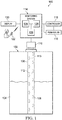
- FIGURE 1 illustrates an example inventory management system 100 having a servo gauge according to this disclosure.
- the system 100 includes a tank 102 that can store one or more materials 104.
- the tank 102 represents any suitable structure for receiving and storing at least one liquid or other material.
- the tank 102 could, for example, represent an oil storage tank or a tank for storing other liquid(s) or other material(s).
- the tank 102 could also have any suitable shape and size.
- the tank 102 could form part of a larger structure.
- the larger structure could represent any fixed or movable structure containing or associated with one or more tanks 102, such as a movable tanker vessel, railcar, or truck or a fixed tank farm.
- a stillpipe 106 having multiple openings 108 could optionally be used in conjunction with a servo gauge 110 to facilitate the measurement of material 104 in the tank 102.
- the openings 108 represent holes, slots, or other apertures that allow material 104 to enter into and leave the stillpipe 106.
- the stillpipe 106 helps to provide a stable reference point for the servo gauge 110 to measure. For instance, the level of material 104 in the stillpipe 106 is generally equal to the level of material 104 outside the stillpipe 106, but the stillpipe 106 helps to reduce or prevent waves or other disturbances to the material 104 outside the stillpipe 106 from affecting level measurements taken inside the stillpipe 106 by the servo gauge 110.
- the stillpipe 106 includes any suitable structure for receiving material and allowing material measurements within the stillpipe.
- the stillpipe 106 can also be located at any suitable position.
- the stillpipe 106 could be attached to the tank's roof, floor, or an upper or lower portion of the tank's shell. Note, however, that the use of the stillpipe 106 is optional and that the servo gauge 110 could operate inside the tank 102 in free space without the use of a stillpipe.
- the servo gauge 110 includes a displacer 112 that is physically raised and lowered within the tank 102 using a measuring wire 113.
- the displacer 112 can sink in the material 104 in the tank 102.
- the apparent weight of the displacer 112 (actual weight minus buoyancy) varies depending on whether the displacer 112 is completely or partially submerged and the type of material in which the displacer 112 is submerged.
- the servo gauge 110 could use the apparent weight of the displacer 112 to identify the level of material 104 in the tank 102.
- the servo gauge 110 can raise and lower the displacer 112 using the measuring wire 113 wrapped around a drum, and the servo gauge 110 can measure the torque or other force on the drum or a structure coupled to the drum (such as a shaft).
- the servo gauge 110 can use the measured force to determine when the displacer 112 has become completely or partially submerged in the material 104, allowing the servo gauge 110 to determine the surface level of the material 104 in the tank 102. Similar operations could be used by the servo gauge 110 to identify different layers of material 104 in the tank 102 since the apparent weight of the displacer 112 can vary depending on the type of material in which it is submerged.
- the servo gauge 110 could be used to identify where an interface exists between water and one or more oil products in the tank 102.
- the servo gauge 110 could further be used to identify a density of one or more materials in the tank 102 since the density of material can affect the apparent weight of the displacer 112.
- the servo gauge 110 includes any suitable structure for measuring one or more characteristics of material in a tank using a displacer.
- the level measurements could take various forms, such as absolute or relative measurements.
- Absolute level measurements could denote distances between the surface of the material 104 or a material interface and the bottom of the tank 102.
- Relative level measurements could denote distances between the top of the material 104 or a material interface and a reference location, such as a reference location known to the servo gauge 110.
- the determined characteristic(s) of the material 104 can be provided from the servo gauge 110 to a monitoring system 114 over a wired or wireless link.
- the monitoring system 114 can use the determined characteristic(s) from the servo gauge 110 in any suitable manner.
- the monitoring system 114 could control automatic loading or unloading of material in the tank 102 by controlling a pump or valve 116 or by providing the determined level to an external controller 118 that controls the pump or valve 116.
- the monitoring system 114 could also notify personnel responsible for controlling the loading or unloading of the tank 102, such as by displaying the determined level on a display 120 or by transmitting the determined level to a wireless or other user device 122.
- the monitoring system 114 could further trigger any suitable alarm, such as when the servo gauge 110 detects a leak or overfill in the tank 102 based on the identified level or other measurements.
- the monitoring system 114 represents any suitable computing or processing system or device, such as a computing device or an industrial process controller.
- the monitoring system 114 includes at least one processing device 124 and at least one memory 126 storing instructions and data used, generated, or collected by the processing device(s) 124.
- the monitoring system 114 can also include at least one interface 128 facilitating communication with external devices or systems like the components 110 and 116-122, such as an Ethernet interface, a radio frequency (RF) transceiver, or other wired or wireless interface.
- RF radio frequency
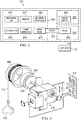
- FIGURES 2 and 3 illustrate example servo gauges 110 for use in an inventory management system according to this disclosure.
- one embodiment of the servo gauge 110 includes three compartments: a drum compartment 202, a drive compartment 204, and a power supply compartment 206.
- the drum compartment 202 includes a drum 208 on which the measuring wire 113 is wound.
- the drum 208 can be rotated in one direction by the drive compartment 204 to lower the displacer 112, and the drum 208 can be rotated in another direction by the drive compartment 204 to raise the displacer 112.
- the drum 208 includes any suitable structure for raising and lowering a displacer via rotation, such as a cylindrical-shaped object having precisely-machined grooves for receiving the measuring wire 113.
- the drive compartment 204 includes a drive train 210, which imparts rotation to the drum 208 via a shaft 212.
- the drive train 210 or shaft 212 could generate a magnetic field, and magnetic coupling can be used to convey torque between the shaft 212 and the drum 208.
- no direct connection may be needed between the drum compartment 202 and the other compartments 204-206.
- other techniques for causing rotation of the drum 208 could be used, such as when the shaft 212 is physically connected to the drum 208.
- the drive train 210 includes any suitable structure for imparting rotation to a drum.
- the drive train 210 includes a stepper motor that causes the drum 208 to rotate in specified steps, meaning the drum 208 does not rotate freely but in defined amounts or "steps.” Each step of the stepper motor should therefore impart a known amount of rotation to the drum 208.
- the drum 208 since the drum 208 has a known diameter or circumference, the length of measuring wire 113 that is dispensed or collected during a single step rotation can be known with a high degree of certainty.
- other embodiments of the drive train 210 could also be used.
- the drive compartment 204 also includes a measuring unit 214, which identifies the torque or other force induced on the drum 208 by the displacer 112 or other characteristic(s) of the measuring wire 113, shaft 212, or drum 208.
- the force induced on the drum 208 can be caused by the apparent weight of the displacer 112. For example, when the displacer 112 is dangling from the measuring wire 113, the measured torque is higher. When the displacer 112 is completely or partially submerged in the material 104, the measured torque is lower.
- the measuring unit 214 includes any suitable structure for measuring at least one characteristic of the servo gauge 110, such as a force transducer. As a particular example, the measuring unit 214 could identify the torque on the drum 208 by measuring the torque on the shaft 212.
- a controller 216 uses measurements from the measuring unit 214 to (among other things) determine the surface level of material 104 in the tank 102, determine a location of one or more material interfaces in the tank 102, or determine a density of material 104 in the tank 102. For example, the controller 216 can cause the drive train 210 to lower the displacer 112. When the displacer 112 is completely or partially submerged, the controller 216 detects the lower torque measurements from the measuring unit 214.
- the controller 216 can track the number of rotations or other operations of the drum 208 and know the length of the measuring wire 113 that has been dispensed or collected, the controller 216 can identify the length of the measuring wire 113 that is between the drum 208 and the displacer 112 when the drop in torque is detected. That length can be used to identify the surface level of material 104 in the tank 102 or the position of a material interface.
- the controller 216 includes any suitable structure for determining a level, density, or other characteristic(s) of material in a tank using a displacer.
- the controller 216 could include at least one processor, microprocessor, microcontroller, field programmable gate array, digital signal processor, or other processing or control device. Instructions and data used, generated, or collected by the controller 216 could be stored in at least one memory 217, which denotes any suitable volatile or non-volatile storage and retrieval device(s).
- the drive compartment 204 further includes a user interface 218 and a network interface 220.
- the user interface 218 facilitates communication between the servo gauge 110 and an operator or other personnel.
- the user interface 218 could provide data from an operator to the controller 216, such as a command to initiate level or density measurements or a command to raise or lower the displacer 112.
- the user interface 218 could also allow the personnel to review measurement data generated by the servo gauge 110.
- the user interface 218 includes any suitable interface for interacting with one or more users, such as a keypad or keyboard and a display.
- the network interface 220 facilitates the communication of data to or from the servo gauge 110.
- the network interface 220 could receive measurements calculated by the servo gauge 110 and transmit the measurements to one or more external destinations (such as the monitoring system 114).
- the network interface 220 includes any suitable structure supporting wired or wireless communications, such as an Ethernet interface, an RF transceiver, or other wired or wireless interface.
- the power supply compartment 206 includes a power supply 222, which provides operating power for the servo gauge 110.
- the power supply 222 could provide power to various components of the drive compartment 204.
- the power supply 222 may or may not supply power to the drum compartment 202.
- the power supply 222 includes any suitable structure for providing power, such as a battery, fuel cell, or solar cell.
- FIGURE 3 illustrates a specific implementation of the servo gauge 110 of FIGURE 2 .
- the servo gauge 110 includes a magnetic coupler 302 that translates rotation of the shaft 212 into rotation of the drum 208.
- the use of magnetic coupling helps to provide fault isolation in the servo gauge 110, although as noted above other embodiments of the drive train 210 could be used.
- a measuring wire 113 used to raise and lower a displacer 112 of a servo gauge 110 often has to be very thin yet strong, reasonably flexible, and compatible with the material 104 in the tank 102 (such as by being resistant to corrosion).
- Stainless steel (AISI 316) is often used as the measuring wire 113, although metals like tantalum or HASTELLOY alloys can be used for chemical applications. Smaller diameters of the measuring wire 113 may be useful since the smaller diameters allow narrower grooves to be used in the drum 208, resulting in less travel of the measuring wire 113 over its measuring height.
- measuring wires 113 with smaller diameters often have a higher elasticity, which means that the measuring wires 113 can elongate more while under load compared to measuring wires 113 with smaller elasticity.
- the higher elasticity may be acceptable since the apparent displacer weight remains substantially constant during use.
- the displacer 112 is submerged in material 104 during use, the higher elasticity of the measuring wire 113 becomes problematic since the loading on the measuring wire 113 can change drastically.
- the different loadings on the measuring wire 113 at different times can cause different portions of the measuring wire 113 to be wound on the drum 208 with different forces or loads. These different forces or loads can cause different portions of the measuring wire 113 to elongate by different amounts. This can create errors in level measurements or other measurements captured by the servo gauge 110. The magnitude of the errors can depend on the wire loading under various conditions, the wire properties, and the tank height. This can be particularly problematic in situations where precise measurements are needed, such as in "custody transfers" and "weights and measures of oil” applications. This problem is also exacerbated when taller tanks 102 are used, which is currently the trend in some industries.
- measuring wires 113 formed from more exotic materials having higher Young's modulus values, meaning the materials are more stiff and show less elasticity.
- chemical compatibility of these wire materials with the materials stored in tanks 102 may be unknown or be more limited than conventional wire materials.
- These wire materials are also often more complex to handle in factories and in the field, may require larger drums in order to spool the measuring wires, and are typically more expensive.
- a compensation algorithm is used to compensate for effects caused by changes in the length of a measuring wire 113 of a servo gauge 110.
- the changes in the length of the measuring wire 113 include both elongation of the measuring wire 113 (such as due to more-than-expected tension on the measuring wire 113) and contraction of the measuring wire 113 (such as due to less-than-expected tension on the measuring wire 113).
- the compensation algorithm uses information from the control mechanism of the servo gauge 110 to measure the tension on the measuring wire 113. While the servo gauge 110 is moving the displacer 112 up or down, the compensation algorithm keeps track of the tension at which the measuring wire 113 is spooled onto the drum 208.
- the servo gauge 110 also measures the tension on the portion of the measuring wire 113 currently hanging off the drum 208. Using these measured tensions, the compensation algorithm is able to estimate the elongation or contraction of the measuring wire 113 and to generate or correct level measurements or other measurements based on the identified elongation or contraction.
- the compensation algorithm allows more accurate measurements to be captured by the servo gauge 110. Moreover, because elongation or contraction of the measuring wire 113 can be estimated and used in servo gauge measurements, there is less need to use exotic materials for the measuring wire 113. In some cases, the compensation algorithm may allow the choice of the measuring wire's material to be based purely on chemical compatibility in an intended application. At the same time, the compensation algorithm may help to reduce factory operations or servo gauge costs by helping to simplify servo gauge production and allow usage of cheaper components.
- the compensation algorithm could be used continuously and automatically with a servo gauge 110.
- the compensation algorithm could be implemented in any suitable manner, such as by using hardware or a combination of hardware and software/firmware instructions.
- the compensation algorithm could be implemented using software/firmware instructions that are stored in the memory 217 and executed by the controller 216 of the servo gauge 110 or that are stored in the memory 126 and executed by the processing device 124 of the monitoring system 114.
- FIGURE 1 illustrates one example of an inventory management system 100 having a servo gauge 110 and FIGURES 2 and 3 illustrate examples of servo gauges 110 for use in an inventory management system
- a system could include any number of tanks, monitoring systems, servo gauges, pumps, valves, controllers, displays, user devices, or other components.
- the makeup and arrangement of the inventory management system 100 are for illustration only. Components could be added, omitted, combined, subdivided, or placed in any other suitable configuration according to particular needs.
- the monitoring system 114 could be incorporated into the servo gauge 110, or the measuring unit 214 and the controller 216 could be combined into a single processing device or other functional unit.
- FIGURE 1 illustrates one operational environment in which a servo gauge compensation algorithm can be used, this functionality could be used in any other suitable system.
- the specific form factors of various components shown in FIGURE 3 are for illustration only.
- FIGURE 4 illustrates an example method 400 for wire length compensation in a servo gauge for an inventory management application according to this disclosure.
- the method 400 shown in FIGURE 4 is described with respect to the servo gauge 110 of FIGURE 2 operating in the system 100 of FIGURE 1 .
- the method 400 could be used with any suitable servo gauge and in any suitable system.
- the operation of a drum in a servo gauge is tracked at step 402.
- the controller 216 could track other ways in which the servo gauge 110 rotates the drum 208.
- the tracking of the drum 208 allows the controller 216 to identify when different segments of the measuring wire 113 are spooled onto or unspooled from the drum 208.
- Force measurements related to the servo gauge are received or obtained at step 404. This could include, for example, the controller 216 receiving force measurements from the measuring unit 214. In some embodiments, the force measurements could identify the torque on the shaft 212 or drum 208 of the servo gauge 110.
- Measurements of tension on the measuring wire are identified using the force measurements at step 406, and the tension measurements for different portions of the measuring wire are stored at step 408.
- the different segments of the measuring wire 113 could denote different unit lengths of the measuring wire 113 (such as different centimeter or meter segments of the measuring wire 113) or different revolutions of the drum 208 (each of which is associated with some segment of the measuring wire 113).
- the tension measurements can be identified and stored as the measuring wire 113 is wound onto and unwound from the drum 208.
- a memory management technique can be used such that the tension measurement for a segment of the measuring wire 113 is stored when that segment is wound onto the drum 208 and discarded when that segment is unwound from the drum 208.
- a default tension measurement could be stored in association with that segment of the measuring wire 113. For instance, the tension at which the measuring wire 113 is wound onto the drum 208 in a factory could be stored in the memory location for that segment.
- a wire compensation value is calculated at step 410. This could include, for example, the controller 216 using at least some of the stored tension measurements to estimate an amount of wire elongation or contraction that has occurred with the measuring wire 113.
- the amount of wire elongation or contraction could be expressed in various ways. For example, wire elongation or contraction could be expressed as an absolute amount of wire elongation or contraction that has occurred (given the tension measurements and properties of the measuring wire 113). Wire elongation or contraction could also be expressed as a relative amount of wire elongation or contraction that has occurred (given the tension measurements and properties of the measuring wire 113) compared to an expected amount of wire elongation or contraction.
- a material measurement is calculated using the servo gauge at step 412 and adjusted using the wire compensation value at step 414.
- This could include, for example, the controller 216 calculating a surface level measurement or an interface level measurement of the material 104 in the tank 102 based on the amount of measuring wire 113 unspooled from the drum 208.
- This could also include the controller 216 adjusting the calculated material measurement using the wire compensation value to compensate for elongation or contraction of the measuring wire 113. Note that while shown as separate steps here, the material measurement calculation and adjustment could be combined into a single calculation or set of calculations, such as when the wire compensation value (or other value representing or based on the estimated amount of wire elongation or contraction) is incorporated directly into the calculation of the material measurement.
- the material measurement is stored, output, or used in some manner at step 416.
- the adjusted material measurement could be used to perform any other suitable functions.
- the controller 216 can help to compensate for elongation or contraction of the measuring wire 113 by taking into account both (i) the tensions on different segments of the measuring wire 113 currently wound around the drum 208 and (ii) the tension on the portion of the measuring wire 113 currently unwound from the drum 208.
- a current force measurement from the measuring unit 214 can be used to identify the tension on the portion of the measuring wire 113 currently unwound from the drum 208. From this, the controller 216 could identify elongation or contraction of that portion of the measuring wire 113.
- Stored force measurements from the measuring unit 214 or stored default force measurements can also be used to identify the tensions on portions of the measuring wire 113 currently wound around the drum 208.
- the controller 216 could identify an overall elongation or contraction of those portions of the measuring wire 113 currently wound around the drum 208. By taking into account those values, the controller 216 can more effectively identify the length of the measuring wire 113 currently unwound from the drum 208, helping to provide more accurate level measurements or other measurements.
- the wire compensation value could be expressed in various ways. In some embodiments, it may be assumed that the measuring wire 113 is wound around the drum 208 at a specific tension, such as a tension established in a factory. It may also be assumed that this tension permits some known level of wire elongation.
- the wire compensation value for this type of servo gauge 110 could be expressed as the difference between the actual elongation or contraction and the known level of wire elongation. Of course, other expressions of the wire compensation value, such as actual estimates of the wire elongation or contraction, could also be used.
- the equation for Young's modulus can help to calculate the expected elongation or contraction of the measuring wire 113 as a function of the tension (force) on the measuring wire 113.
- E denotes the Young's modulus (such as in Pascals)
- F denotes the applied force (such as in Newtons)
- L denotes the original length of the measuring wire 113 (such as in meters)
- A denotes the cross-sectional area of the measuring wire 113 (such as in square meters)
- ⁇ L denotes the change in length of the measuring wire 113 (such as in meters).
- the difference between an expected change in the measuring wire's length and an actual change in the measuring wire's length could be used as the wire compensation value for a specific segment of the measuring wire 113.
- the reference tension F ref could be equal for all segments of the measuring wire 113, although this need not be the case.
- Wire compensation values could be calculated in this manner for different segments of the measuring wire 113, including one or more segments of the measuring wire 113 hanging from the drum 208 and one or more segments of the measuring wire 113 currently wound around the drum 208.
- the wire compensation values for the different segments could then be combined to create a final wire compensation value that is used to adjust a material measurement.
- FIGURE 4 illustrates one example of a method 400 for wire length compensation in a servo gauge for an inventory management application
- various changes may be made to FIGURE 4 .
- various steps in FIGURE 4 could overlap, occur in parallel, occur in a different order, or occur any number of times.
- the wire length correction described in FIGURE 4 could be combined with one or more corrections related to other aspects of a servo gauge, such as temperature corrections related to the drum 208, temperature corrections of the "in tank” measuring wire, temperature corrections of the magnetic coupling, and density corrections for the immersion of the displacer 112.
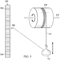
- FIGURES 5 and 6A through 6C illustrate an example memory management technique for supporting wire length compensation in a servo gauge for an inventory management application according to this disclosure.
- the memory management technique shown here is described with respect to the servo gauge 110 of FIGURE 2 operating in the system 100 of FIGURE 1 .
- the memory management technique could be used with any suitable servo gauge and in any suitable system.
- a memory 500 includes a number of memory locations 502.
- the memory 500 could, for example, denote a portion of the memory 217 in the servo gauge 110 or the memory 126 in the monitoring system 114.
- Each memory location 502 can be used to store a tension measurement 504 associated with a different segment of the measuring wire 113.
- the number of memory locations 502 can be based on the number of segments of the measuring wire 113, and the number of segments of the measuring wire 113 can depend on number of the unit lengths forming the measuring wire 113 or the number of drum revolutions required to unwind the measuring wire 113 completely.
- the tension measurements 504 in the memory locations 502 for those segments of the measuring wire 113 can be discarded or not used any longer.
- a pointer 506 is associated with a current location of the displacer 112. Memory locations 502 above the pointer 506 can contain discarded or unused tension measurements 504 that may not be used to identify wire compensation values. Memory locations 502 below the pointer 506 can contain tension measurements 504 that may continue to be used to identify wire compensation values.
- all memory locations 502 in the memory 500 could include default tension measurements 504, such as measurements 504 taken while the measuring wire 113 is being wound around the drum 208 in a factory.
- the default tension measurements 504 may or may not be equal.
- the memory locations 502 for the unwound segments can be discarded, while the remaining memory locations 502 continue to contain measurements 504 for unwound segments of the measuring wire 113.
- the memory locations 502 for the newly rewound segments can be filled with new tension measurements 504 and used in subsequent wire compensation value computations.
- FIGURES 6A through 6C An example of this is shown in FIGURES 6A through 6C .
- the displacer 112 is at a relatively high location, and most memory locations 502 contain tension measurements 504.
- the used memory locations 502 are shaded similarly to denote that the tension measurements 504 are generally equal, which could occur when the servo gauge 110 is first being used and the stored tension measurements 504 are default or factory-defined values.
- the displacer 112 is moved back up, and the pointer 506 is moved up, indicating that new tension measurements 504 are being added into memory locations 502.
- the new tension measurements 504 are shown here as having different shadings, indicating that the new tension measurements 504 need not be generally equal. This can occur, for example, when the displacer 112 is raised and different tensions are applied on the measuring wire 113 at different times.
- the controller 216 could use the equations described above. As an example, for each memory location 502 at or below the pointer 506 in FIGURE 6C , the controller 216 could use Equation (3) above to calculate a length correction for the wire segment associated with that memory location 502. The controller 216 could then use Equation (4) above to combine the length corrections for the segments into a final length correction for the current measurement.
- the portion of the measuring wire 113 hanging from the drum 208 may or may not have a value stored in the memory 500. If not stored in the memory 500, the controller 216 could use the current output of the measuring unit 214 for the portion of the measuring wire 113 hanging from the drum 208.
- the compensation algorithm described above could be implemented using a limited amount of memory.
- the tension measurements for the measuring wire 113 in some embodiments can be limited to one measurement per measuring wire segment.
- other compensation calculations that use more measurements could also be used.
- FIGURES 5 and 6A through 6C illustrate one example of a memory management technique for supporting wire length compensation in a servo gauge for an inventory management application
- various changes may be made to FIGURES 5 and 6A through 6C .
- the number of memory locations 502 could vary depending on the implementation.
- other techniques could be used to store or use the tension measurements for wire length compensation.
- the apparatus and method according to the present invention are implemented or supported by a computer program that is formed from computer readable program code and that is embodied in a computer readable medium.
- computer readable program code includes any type of computer code, including source code, object code, and executable code.
- computer readable medium includes any type of medium capable of being accessed by a computer, such as read only memory (ROM), random access memory (RAM), a hard disk drive, a compact disc (CD), a digital video disc (DVD), or any other type of memory.
- ROM read only memory
- RAM random access memory
- CD compact disc
- DVD digital video disc
- a “non-transitory” computer readable medium excludes wired, wireless, optical, or other communication links that transport transitory electrical or other signals.
- a non-transitory computer readable medium includes media where data can be permanently stored and media where data can be stored and later overwritten, such as a rewritable optical disc or an erasable memory device.
- application and “program” refer to one or more computer programs, software components, sets of instructions, procedures, functions, objects, classes, instances, related data, or a portion thereof adapted for implementation in a suitable computer code (including source code, object code, or executable code).
- program refers to one or more computer programs, software components, sets of instructions, procedures, functions, objects, classes, instances, related data, or a portion thereof adapted for implementation in a suitable computer code (including source code, object code, or executable code).
- communicate as well as derivatives thereof, encompasses both direct and indirect communication.
- the term “or” is inclusive, meaning and/or.
- phrases "associated with,” as well as derivatives thereof, may mean to include, be included within, interconnect with, contain, be contained within, connect to or with, couple to or with, be communicable with, cooperate with, interleave, juxtapose, be proximate to, be bound to or with, have, have a property of, have a relationship to or with, or the like.
- the phrase "at least one of,” when used with a list of items, means that different combinations of one or more of the listed items may be used, and only one item in the list may be needed. For example, "at least one of: A, B, and C" includes any of the following combinations: A, B, C, A and B, A and C, B and C, and A and B and C.
Landscapes
- Physics & Mathematics (AREA)
- General Physics & Mathematics (AREA)
- Fluid Mechanics (AREA)
- Thermal Sciences (AREA)
- Level Indicators Using A Float (AREA)
- Controlling Rewinding, Feeding, Winding, Or Abnormalities Of Webs (AREA)
Description
- This disclosure relates generally to inventory management systems. More specifically, this disclosure relates to an apparatus and method for wire length compensation in a servo gauge for an inventory management application.
- Processing facilities and other facilities routinely include tanks for storing liquid, solid, or other materials. For example, storage tanks are routinely used in tank farm facilities and other storage facilities to store oil or other materials. Processing facilities also often include tanks for implementing industrial processes. Storage tanks could include above-ground structures and below-ground structures.
- Often times, it is necessary or desirable to measure the amount of material stored in a tank. This may be useful, for example, during loading of material into the tank or unloading of material from the tank or during liquid stock accounting. As a particular example, "legal metrology" often requires highly accurate measurements from level gauging instruments installed on the roof of a tank, such as during custody transfers or when levying taxes or duties. In bulk storage tanks, an error of one millimeter in a level reading can correspond to several cubic meters of volumetric error. This can result in losses of thousands of dollars for one or more parties. Moreover, this can have negative effects on stock reconciliation, which involves attempting to track where materials are located and how materials are lost.
- Among other approaches, servo gauges have been used to measure the level of material in a tank. A servo gauge is an electro-mechanical type of automatic tank gauge that typically raises and lowers a displacer, which sinks in material within a tank. The servo gauge can determine the level of material in the tank based on changes in the displacer's apparent weight, which changes depending on (among other things) whether the displacer is hanging in the air or submerged in the material.
- The displacer of a servo gauge is typically suspended by a thin yet very strong wire, which is often spooled on a grooved measuring drum. The servo gauge rotates the drum to raise and lower the displacer. By continuously measuring the apparent weight of the displacer, the servo gauge can sense whether the displacer is above, partially submerged, or fully submerged. The servo gauge may then attempt to keep the displacer at a fixed position relative to the surface of the material in the tank. By doing so, the servo gauge can calculate the material level in the tank based on the amount of wire spooled off the drum. It may also be possible for a servo gauge to measure the density of different layers of material (such as water and oil) in a tank.
-
DE2544038 discloses a liquid level indicator comprising a body arranged to remain at the surface of a liquid whose level is to be indicated, and connected by a line to a drum on which the line is wound, and a tensioning device acting on said drum to produce a constant force on said body such that said body remains at the surface of the liquid whatever its level. -
EP 0096432 A1 (van der Pol ) describes measuring a level and taking into account the tension of the portion of the wire that is currently unwound from the drum. -
DE 102014118067 (Kamei ) describes using a modified torsion of the drum due to a change in length of the wound portion of the wire, but does not take into account the tension of this wound portion. -
DE 1245158 B (Arns ) describes automatic compensation for the weight of the rope. -
US 5166589 A (Breden ) describes a modified wire length due to temperature effects, but does not disclose to take into account the tension of the wound portion of the wire. -
DE 20 2004018047 U1 describes a miscalculation of the length of the wound portion of the wire due to a change in wound diameter, but does not disclose to take into account the tension of the wound portion of the wire. - This disclosure provides an apparatus and method for wire length compensation in a servo gauge for an inventory management application, set out in accordance with the appended claims.
- In a first embodiment, a method includes measuring tensions on a measuring wire coupled to a displacer of a servo gauge. The servo gauge is configured to raise and lower the displacer using a drum around which the measuring wire is wound. Different measured tensions are associated with different segments of the measuring wire, wherein said tensions include (i) the tensions on different segments of the measuring wire currently wound around the drum and (ii) the tension on the portion of the measuring wire currently unwound from the drum. The method also includes calculating or adjusting a measurement associated with material in a tank using the measured tensions to account for a change in a length of the measuring wire.
- In a second embodiment, an apparatus includes a drum configured to be rotated in order to raise and lower a displacer within a tank and a measuring wire coupling the drum and the displacer. The apparatus also includes a sensor configured to measure tensions on the measuring wire such that different measured tensions are associated with different segments of the measuring wire, wherein said tensions include (i) the tensions on different segments of the measuring wire currently wound around the drum and (ii) the tension on the portion of the measuring wire currently unwound from the drum. The apparatus further includes a controller configured to calculate or adjust a measurement associated with material in the tank using the measured tensions to account for a change in a length of the measuring wire.
- In a third embodiment, a non-transitory computer readable medium contains instructions that, when executed by at least one processor, cause the at least one processor to obtain tensions on a measuring wire coupled to a displacer of a servo gauge. The servo gauge is configured to raise and lower the displacer using a drum around which the measuring wire is wound. Different measured tensions are associated with different segments of the measuring wire, wherein said tensions include (i) the tensions on different segments of the measuring wire currently wound around the drum and (ii) the tension on the portion of the measuring wire currently unwound from the drum. The medium also contains instructions that, when executed by the at least one processor, cause the at least one processor to calculate or adjust a measurement associated with material in a tank using the measured tensions to account for a change in a length of the measuring wire.
- Other technical features may be readily apparent to one skilled in the art from the following figures, descriptions, and claims.
- For a more complete understanding of this disclosure, reference is now made to the following description, taken in conjunction with the accompanying drawings, in which:
-
FIGURE 1 illustrates an example inventory management system having a servo gauge according to this disclosure; -
FIGURES 2 and 3 illustrate example servo gauges for use in an inventory management system according to this disclosure; -
FIGURE 4 illustrates an example method for wire length compensation in a servo gauge for an inventory management application according to this disclosure; and -
FIGURES 5 and6A through 6C illustrate an example memory management technique for supporting wire length compensation in a servo gauge for an inventory management application according to this disclosure. -
FIGURES 1 through 6C , discussed below, and the various embodiments used to describe the principles of the present invention in this patent document are by way of illustration only and should not be construed in any way to limit the scope of the invention. Those skilled in the art will understand that the principles of the invention may be implemented in any type of suitably arranged device or system. -
FIGURE 1 illustrates an exampleinventory management system 100 having a servo gauge according to this disclosure. As shown inFIGURE 1 , thesystem 100 includes atank 102 that can store one ormore materials 104. Thetank 102 represents any suitable structure for receiving and storing at least one liquid or other material. Thetank 102 could, for example, represent an oil storage tank or a tank for storing other liquid(s) or other material(s). Thetank 102 could also have any suitable shape and size. Further, thetank 102 could form part of a larger structure. The larger structure could represent any fixed or movable structure containing or associated with one ormore tanks 102, such as a movable tanker vessel, railcar, or truck or a fixed tank farm. - A
stillpipe 106 havingmultiple openings 108 could optionally be used in conjunction with aservo gauge 110 to facilitate the measurement ofmaterial 104 in thetank 102. Theopenings 108 represent holes, slots, or other apertures that allowmaterial 104 to enter into and leave thestillpipe 106. Thestillpipe 106 helps to provide a stable reference point for theservo gauge 110 to measure. For instance, the level ofmaterial 104 in thestillpipe 106 is generally equal to the level ofmaterial 104 outside thestillpipe 106, but thestillpipe 106 helps to reduce or prevent waves or other disturbances to thematerial 104 outside thestillpipe 106 from affecting level measurements taken inside thestillpipe 106 by theservo gauge 110. Thestillpipe 106 includes any suitable structure for receiving material and allowing material measurements within the stillpipe. Thestillpipe 106 can also be located at any suitable position. For instance, thestillpipe 106 could be attached to the tank's roof, floor, or an upper or lower portion of the tank's shell. Note, however, that the use of thestillpipe 106 is optional and that theservo gauge 110 could operate inside thetank 102 in free space without the use of a stillpipe. - The
servo gauge 110 includes adisplacer 112 that is physically raised and lowered within thetank 102 using ameasuring wire 113. Thedisplacer 112 can sink in thematerial 104 in thetank 102. The apparent weight of the displacer 112 (actual weight minus buoyancy) varies depending on whether thedisplacer 112 is completely or partially submerged and the type of material in which thedisplacer 112 is submerged. Theservo gauge 110 could use the apparent weight of thedisplacer 112 to identify the level ofmaterial 104 in thetank 102. For example, theservo gauge 110 can raise and lower thedisplacer 112 using themeasuring wire 113 wrapped around a drum, and theservo gauge 110 can measure the torque or other force on the drum or a structure coupled to the drum (such as a shaft). Theservo gauge 110 can use the measured force to determine when thedisplacer 112 has become completely or partially submerged in thematerial 104, allowing theservo gauge 110 to determine the surface level of the material 104 in thetank 102. Similar operations could be used by theservo gauge 110 to identify different layers ofmaterial 104 in thetank 102 since the apparent weight of thedisplacer 112 can vary depending on the type of material in which it is submerged. For instance, theservo gauge 110 could be used to identify where an interface exists between water and one or more oil products in thetank 102. Theservo gauge 110 could further be used to identify a density of one or more materials in thetank 102 since the density of material can affect the apparent weight of thedisplacer 112. Theservo gauge 110 includes any suitable structure for measuring one or more characteristics of material in a tank using a displacer. - With respect to level measurements (such as surface level measurements and material interface measurements), the level measurements could take various forms, such as absolute or relative measurements. Absolute level measurements could denote distances between the surface of the material 104 or a material interface and the bottom of the
tank 102. Relative level measurements could denote distances between the top of the material 104 or a material interface and a reference location, such as a reference location known to theservo gauge 110. - The determined characteristic(s) of the material 104 can be provided from the
servo gauge 110 to amonitoring system 114 over a wired or wireless link. Themonitoring system 114 can use the determined characteristic(s) from theservo gauge 110 in any suitable manner. For example, themonitoring system 114 could control automatic loading or unloading of material in thetank 102 by controlling a pump orvalve 116 or by providing the determined level to anexternal controller 118 that controls the pump orvalve 116. Themonitoring system 114 could also notify personnel responsible for controlling the loading or unloading of thetank 102, such as by displaying the determined level on adisplay 120 or by transmitting the determined level to a wireless orother user device 122. Themonitoring system 114 could further trigger any suitable alarm, such as when theservo gauge 110 detects a leak or overfill in thetank 102 based on the identified level or other measurements. - The
monitoring system 114 represents any suitable computing or processing system or device, such as a computing device or an industrial process controller. In particular embodiments, themonitoring system 114 includes at least oneprocessing device 124 and at least onememory 126 storing instructions and data used, generated, or collected by the processing device(s) 124. Themonitoring system 114 can also include at least oneinterface 128 facilitating communication with external devices or systems like thecomponents 110 and 116-122, such as an Ethernet interface, a radio frequency (RF) transceiver, or other wired or wireless interface. -
FIGURES 2 and 3 illustrate example servo gauges 110 for use in an inventory management system according to this disclosure. As shown inFIGURE 2 , one embodiment of theservo gauge 110 includes three compartments: adrum compartment 202, adrive compartment 204, and apower supply compartment 206. Thedrum compartment 202 includes adrum 208 on which themeasuring wire 113 is wound. Thedrum 208 can be rotated in one direction by thedrive compartment 204 to lower thedisplacer 112, and thedrum 208 can be rotated in another direction by thedrive compartment 204 to raise thedisplacer 112. Thedrum 208 includes any suitable structure for raising and lowering a displacer via rotation, such as a cylindrical-shaped object having precisely-machined grooves for receiving themeasuring wire 113. - The
drive compartment 204 includes adrive train 210, which imparts rotation to thedrum 208 via ashaft 212. For example, thedrive train 210 orshaft 212 could generate a magnetic field, and magnetic coupling can be used to convey torque between theshaft 212 and thedrum 208. In these embodiments, no direct connection may be needed between thedrum compartment 202 and the other compartments 204-206. However, other techniques for causing rotation of thedrum 208 could be used, such as when theshaft 212 is physically connected to thedrum 208. Thedrive train 210 includes any suitable structure for imparting rotation to a drum. In particular embodiments, thedrive train 210 includes a stepper motor that causes thedrum 208 to rotate in specified steps, meaning thedrum 208 does not rotate freely but in defined amounts or "steps." Each step of the stepper motor should therefore impart a known amount of rotation to thedrum 208. In these embodiments, since thedrum 208 has a known diameter or circumference, the length of measuringwire 113 that is dispensed or collected during a single step rotation can be known with a high degree of certainty. However, other embodiments of thedrive train 210 could also be used. - The
drive compartment 204 also includes a measuringunit 214, which identifies the torque or other force induced on thedrum 208 by thedisplacer 112 or other characteristic(s) of themeasuring wire 113,shaft 212, ordrum 208. The force induced on thedrum 208 can be caused by the apparent weight of thedisplacer 112. For example, when thedisplacer 112 is dangling from themeasuring wire 113, the measured torque is higher. When thedisplacer 112 is completely or partially submerged in thematerial 104, the measured torque is lower. The measuringunit 214 includes any suitable structure for measuring at least one characteristic of theservo gauge 110, such as a force transducer. As a particular example, the measuringunit 214 could identify the torque on thedrum 208 by measuring the torque on theshaft 212. - A
controller 216 uses measurements from the measuringunit 214 to (among other things) determine the surface level ofmaterial 104 in thetank 102, determine a location of one or more material interfaces in thetank 102, or determine a density ofmaterial 104 in thetank 102. For example, thecontroller 216 can cause thedrive train 210 to lower thedisplacer 112. When thedisplacer 112 is completely or partially submerged, thecontroller 216 detects the lower torque measurements from the measuringunit 214. Since thecontroller 216 can track the number of rotations or other operations of thedrum 208 and know the length of themeasuring wire 113 that has been dispensed or collected, thecontroller 216 can identify the length of themeasuring wire 113 that is between thedrum 208 and thedisplacer 112 when the drop in torque is detected. That length can be used to identify the surface level ofmaterial 104 in thetank 102 or the position of a material interface. - The
controller 216 includes any suitable structure for determining a level, density, or other characteristic(s) of material in a tank using a displacer. As particular examples, thecontroller 216 could include at least one processor, microprocessor, microcontroller, field programmable gate array, digital signal processor, or other processing or control device. Instructions and data used, generated, or collected by thecontroller 216 could be stored in at least onememory 217, which denotes any suitable volatile or non-volatile storage and retrieval device(s). - In this example, the
drive compartment 204 further includes auser interface 218 and anetwork interface 220. Theuser interface 218 facilitates communication between theservo gauge 110 and an operator or other personnel. Theuser interface 218 could provide data from an operator to thecontroller 216, such as a command to initiate level or density measurements or a command to raise or lower thedisplacer 112. Theuser interface 218 could also allow the personnel to review measurement data generated by theservo gauge 110. Theuser interface 218 includes any suitable interface for interacting with one or more users, such as a keypad or keyboard and a display. - The
network interface 220 facilitates the communication of data to or from theservo gauge 110. For example, thenetwork interface 220 could receive measurements calculated by theservo gauge 110 and transmit the measurements to one or more external destinations (such as the monitoring system 114). Thenetwork interface 220 includes any suitable structure supporting wired or wireless communications, such as an Ethernet interface, an RF transceiver, or other wired or wireless interface. - The
power supply compartment 206 includes apower supply 222, which provides operating power for theservo gauge 110. For example, thepower supply 222 could provide power to various components of thedrive compartment 204. Depending on the implementation, thepower supply 222 may or may not supply power to thedrum compartment 202. Thepower supply 222 includes any suitable structure for providing power, such as a battery, fuel cell, or solar cell. -
FIGURE 3 illustrates a specific implementation of theservo gauge 110 ofFIGURE 2 . As shown inFIGURE 3 , theservo gauge 110 includes amagnetic coupler 302 that translates rotation of theshaft 212 into rotation of thedrum 208. The use of magnetic coupling helps to provide fault isolation in theservo gauge 110, although as noted above other embodiments of thedrive train 210 could be used. - In some embodiments, a
measuring wire 113 used to raise and lower adisplacer 112 of aservo gauge 110 often has to be very thin yet strong, reasonably flexible, and compatible with the material 104 in the tank 102 (such as by being resistant to corrosion). Stainless steel (AISI 316) is often used as themeasuring wire 113, although metals like tantalum or HASTELLOY alloys can be used for chemical applications. Smaller diameters of themeasuring wire 113 may be useful since the smaller diameters allow narrower grooves to be used in thedrum 208, resulting in less travel of themeasuring wire 113 over its measuring height. - Unfortunately, measuring
wires 113 with smaller diameters often have a higher elasticity, which means that the measuringwires 113 can elongate more while under load compared to measuringwires 113 with smaller elasticity. For some servo gauge applications, such as where thedisplacer 112 is moved to remain at the surface of thematerial 104, the higher elasticity may be acceptable since the apparent displacer weight remains substantially constant during use. However, if thedisplacer 112 is submerged inmaterial 104 during use, the higher elasticity of themeasuring wire 113 becomes problematic since the loading on themeasuring wire 113 can change drastically. - The different loadings on the
measuring wire 113 at different times can cause different portions of themeasuring wire 113 to be wound on thedrum 208 with different forces or loads. These different forces or loads can cause different portions of themeasuring wire 113 to elongate by different amounts. This can create errors in level measurements or other measurements captured by theservo gauge 110. The magnitude of the errors can depend on the wire loading under various conditions, the wire properties, and the tank height. This can be particularly problematic in situations where precise measurements are needed, such as in "custody transfers" and "weights and measures of oil" applications. This problem is also exacerbated whentaller tanks 102 are used, which is currently the trend in some industries. - One way this type of problem could be alleviated involves the use of measuring
wires 113 formed from more exotic materials having higher Young's modulus values, meaning the materials are more stiff and show less elasticity. However, the chemical compatibility of these wire materials with the materials stored intanks 102 may be unknown or be more limited than conventional wire materials. These wire materials are also often more complex to handle in factories and in the field, may require larger drums in order to spool the measuring wires, and are typically more expensive. - In accordance with this disclosure, a compensation algorithm is used to compensate for effects caused by changes in the length of a
measuring wire 113 of aservo gauge 110. The changes in the length of themeasuring wire 113 include both elongation of the measuring wire 113 (such as due to more-than-expected tension on the measuring wire 113) and contraction of the measuring wire 113 (such as due to less-than-expected tension on the measuring wire 113). As described in more detail below, the compensation algorithm uses information from the control mechanism of theservo gauge 110 to measure the tension on themeasuring wire 113. While theservo gauge 110 is moving thedisplacer 112 up or down, the compensation algorithm keeps track of the tension at which themeasuring wire 113 is spooled onto thedrum 208. Theservo gauge 110 also measures the tension on the portion of themeasuring wire 113 currently hanging off thedrum 208. Using these measured tensions, the compensation algorithm is able to estimate the elongation or contraction of themeasuring wire 113 and to generate or correct level measurements or other measurements based on the identified elongation or contraction. - In this way, the compensation algorithm allows more accurate measurements to be captured by the
servo gauge 110. Moreover, because elongation or contraction of themeasuring wire 113 can be estimated and used in servo gauge measurements, there is less need to use exotic materials for themeasuring wire 113. In some cases, the compensation algorithm may allow the choice of the measuring wire's material to be based purely on chemical compatibility in an intended application. At the same time, the compensation algorithm may help to reduce factory operations or servo gauge costs by helping to simplify servo gauge production and allow usage of cheaper components. - In some embodiments, the compensation algorithm could be used continuously and automatically with a
servo gauge 110. Also, the compensation algorithm could be implemented in any suitable manner, such as by using hardware or a combination of hardware and software/firmware instructions. As a particular example, the compensation algorithm could be implemented using software/firmware instructions that are stored in thememory 217 and executed by thecontroller 216 of theservo gauge 110 or that are stored in thememory 126 and executed by theprocessing device 124 of themonitoring system 114. - Additional details regarding specific implementations of the servo gauge compensation algorithm are provided below. Note that these details relate to specific implementations of the servo gauge compensation algorithm and that other implementations of the compensation algorithm could be used.
- Although
FIGURE 1 illustrates one example of aninventory management system 100 having aservo gauge 110 andFIGURES 2 and 3 illustrate examples of servo gauges 110 for use in an inventory management system, various changes may be made toFIGURES 1 through 3 . For example, a system could include any number of tanks, monitoring systems, servo gauges, pumps, valves, controllers, displays, user devices, or other components. Also, the makeup and arrangement of theinventory management system 100 are for illustration only. Components could be added, omitted, combined, subdivided, or placed in any other suitable configuration according to particular needs. As particular examples, themonitoring system 114 could be incorporated into theservo gauge 110, or the measuringunit 214 and thecontroller 216 could be combined into a single processing device or other functional unit. Further, whileFIGURE 1 illustrates one operational environment in which a servo gauge compensation algorithm can be used, this functionality could be used in any other suitable system. In addition, the specific form factors of various components shown inFIGURE 3 are for illustration only. -
FIGURE 4 illustrates anexample method 400 for wire length compensation in a servo gauge for an inventory management application according to this disclosure. For ease of explanation, themethod 400 shown inFIGURE 4 is described with respect to theservo gauge 110 ofFIGURE 2 operating in thesystem 100 ofFIGURE 1 . However, themethod 400 could be used with any suitable servo gauge and in any suitable system. - As shown in
FIGURE 4 , the operation of a drum in a servo gauge is tracked atstep 402. This could include, for example, thecontroller 216 of theservo gauge 110 tracking the number of steps that thedrive train 210 uses to rotate thedrum 208 of theservo gauge 110. However, thecontroller 216 could track other ways in which theservo gauge 110 rotates thedrum 208. The tracking of thedrum 208 allows thecontroller 216 to identify when different segments of themeasuring wire 113 are spooled onto or unspooled from thedrum 208. - Force measurements related to the servo gauge are received or obtained at
step 404. This could include, for example, thecontroller 216 receiving force measurements from the measuringunit 214. In some embodiments, the force measurements could identify the torque on theshaft 212 or drum 208 of theservo gauge 110. - Measurements of tension on the measuring wire are identified using the force measurements at
step 406, and the tension measurements for different portions of the measuring wire are stored atstep 408. This could include, for example, thecontroller 216 using the force measurements as the tension measurements or processing the force measurements in some way to generate the tension measurements. This could also include thecontroller 216 identifying the tension measurements for different segments of themeasuring wire 113. The different segments of themeasuring wire 113 could denote different unit lengths of the measuring wire 113 (such as different centimeter or meter segments of the measuring wire 113) or different revolutions of the drum 208 (each of which is associated with some segment of the measuring wire 113). - The tension measurements can be identified and stored as the
measuring wire 113 is wound onto and unwound from thedrum 208. As explained below, a memory management technique can be used such that the tension measurement for a segment of themeasuring wire 113 is stored when that segment is wound onto thedrum 208 and discarded when that segment is unwound from thedrum 208. In some embodiments, if a segment of themeasuring wire 113 has not yet been unwound from thedrum 208 and then spooled back onto thedrum 208, a default tension measurement could be stored in association with that segment of themeasuring wire 113. For instance, the tension at which themeasuring wire 113 is wound onto thedrum 208 in a factory could be stored in the memory location for that segment. - A wire compensation value is calculated at
step 410. This could include, for example, thecontroller 216 using at least some of the stored tension measurements to estimate an amount of wire elongation or contraction that has occurred with themeasuring wire 113. Note that the amount of wire elongation or contraction could be expressed in various ways. For example, wire elongation or contraction could be expressed as an absolute amount of wire elongation or contraction that has occurred (given the tension measurements and properties of the measuring wire 113). Wire elongation or contraction could also be expressed as a relative amount of wire elongation or contraction that has occurred (given the tension measurements and properties of the measuring wire 113) compared to an expected amount of wire elongation or contraction. - A material measurement is calculated using the servo gauge at
step 412 and adjusted using the wire compensation value atstep 414. This could include, for example, thecontroller 216 calculating a surface level measurement or an interface level measurement of the material 104 in thetank 102 based on the amount of measuringwire 113 unspooled from thedrum 208. This could also include thecontroller 216 adjusting the calculated material measurement using the wire compensation value to compensate for elongation or contraction of themeasuring wire 113. Note that while shown as separate steps here, the material measurement calculation and adjustment could be combined into a single calculation or set of calculations, such as when the wire compensation value (or other value representing or based on the estimated amount of wire elongation or contraction) is incorporated directly into the calculation of the material measurement. - The material measurement is stored, output, or used in some manner at
step 416. This could include, for example, thecontroller 216 displaying the adjusted material measurement on a local display, such as theuser interface 218. This could also include thecontroller 216 providing the adjusted material measurement to thenetwork interface 220 for transmission to themonitoring system 114,controller 118,display 120, oruser device 122. The adjusted material measurement could be used to perform any other suitable functions. - The
controller 216 according to the present invention can help to compensate for elongation or contraction of themeasuring wire 113 by taking into account both (i) the tensions on different segments of themeasuring wire 113 currently wound around thedrum 208 and (ii) the tension on the portion of themeasuring wire 113 currently unwound from thedrum 208. For example, a current force measurement from the measuringunit 214 can be used to identify the tension on the portion of themeasuring wire 113 currently unwound from thedrum 208. From this, thecontroller 216 could identify elongation or contraction of that portion of themeasuring wire 113. Stored force measurements from the measuringunit 214 or stored default force measurements can also be used to identify the tensions on portions of themeasuring wire 113 currently wound around thedrum 208. From that, thecontroller 216 could identify an overall elongation or contraction of those portions of themeasuring wire 113 currently wound around thedrum 208. By taking into account those values, thecontroller 216 can more effectively identify the length of themeasuring wire 113 currently unwound from thedrum 208, helping to provide more accurate level measurements or other measurements. - Again, note that the wire compensation value could be expressed in various ways. In some embodiments, it may be assumed that the
measuring wire 113 is wound around thedrum 208 at a specific tension, such as a tension established in a factory. It may also be assumed that this tension permits some known level of wire elongation. The wire compensation value for this type ofservo gauge 110 could be expressed as the difference between the actual elongation or contraction and the known level of wire elongation. Of course, other expressions of the wire compensation value, such as actual estimates of the wire elongation or contraction, could also be used. - In particular embodiments, the equation for Young's modulus can help to calculate the expected elongation or contraction of the
measuring wire 113 as a function of the tension (force) on themeasuring wire 113. This equation can be expressed as:
measuring wire 113 as follows:
- In some embodiments, the difference between an expected change in the measuring wire's length and an actual change in the measuring wire's length could be used as the wire compensation value for a specific segment of the
measuring wire 113. In these embodiments, a wire compensation value ΔLi for the ith segment of themeasuring wire 113 could be expressed as:
measuring wire 113 and Fref denotes a reference tension (force) for at least that segment of themeasuring wire 113. In particular embodiments, the reference tension Fref could be equal for all segments of themeasuring wire 113, although this need not be the case. - Wire compensation values could be calculated in this manner for different segments of the
measuring wire 113, including one or more segments of themeasuring wire 113 hanging from thedrum 208 and one or more segments of themeasuring wire 113 currently wound around thedrum 208. The wire compensation values for the different segments could then be combined to create a final wire compensation value that is used to adjust a material measurement. In some embodiments, the final wire compensation value Wirecorr could be expressed as:
measuring wire 113 wound around thedrum 208, and ΔLfree denotes a wire compensation value for the segment(s) of themeasuring wire 113 hanging from the drum 208 (and not wound around the drum 208). - Although
FIGURE 4 illustrates one example of amethod 400 for wire length compensation in a servo gauge for an inventory management application, various changes may be made toFIGURE 4 . For example, while shown as a series of steps, various steps inFIGURE 4 could overlap, occur in parallel, occur in a different order, or occur any number of times. Also, the wire length correction described inFIGURE 4 could be combined with one or more corrections related to other aspects of a servo gauge, such as temperature corrections related to thedrum 208, temperature corrections of the "in tank" measuring wire, temperature corrections of the magnetic coupling, and density corrections for the immersion of thedisplacer 112. Two specific examples of additional types of corrections that could be combined with the wire length correction ofFIGURE 4 are described inU.S. Patent Application No. 14/875,325 filed on October 5, 2015 U.S. Patent Application No. 15/207,693 filed on July 12, 2016 -
FIGURES 5 and6A through 6C illustrate an example memory management technique for supporting wire length compensation in a servo gauge for an inventory management application according to this disclosure. For ease of explanation, the memory management technique shown here is described with respect to theservo gauge 110 ofFIGURE 2 operating in thesystem 100 ofFIGURE 1 . However, the memory management technique could be used with any suitable servo gauge and in any suitable system. - As shown in
FIGURE 5 , amemory 500 includes a number ofmemory locations 502. Thememory 500 could, for example, denote a portion of thememory 217 in theservo gauge 110 or thememory 126 in themonitoring system 114. Eachmemory location 502 can be used to store atension measurement 504 associated with a different segment of themeasuring wire 113. The number ofmemory locations 502 can be based on the number of segments of themeasuring wire 113, and the number of segments of themeasuring wire 113 can depend on number of the unit lengths forming themeasuring wire 113 or the number of drum revolutions required to unwind themeasuring wire 113 completely. - As segments of the
measuring wire 113 are unwound from thedrum 208, thetension measurements 504 in thememory locations 502 for those segments of themeasuring wire 113 can be discarded or not used any longer. In this example, apointer 506 is associated with a current location of thedisplacer 112.Memory locations 502 above thepointer 506 can contain discarded orunused tension measurements 504 that may not be used to identify wire compensation values.Memory locations 502 below thepointer 506 can containtension measurements 504 that may continue to be used to identify wire compensation values. - Initially, all
memory locations 502 in thememory 500 could includedefault tension measurements 504, such asmeasurements 504 taken while themeasuring wire 113 is being wound around thedrum 208 in a factory. Thedefault tension measurements 504 may or may not be equal. As themeasuring wire 113 is unwound, thememory locations 502 for the unwound segments can be discarded, while the remainingmemory locations 502 continue to containmeasurements 504 for unwound segments of themeasuring wire 113. As themeasuring wire 113 is wound back up, thememory locations 502 for the newly rewound segments can be filled withnew tension measurements 504 and used in subsequent wire compensation value computations. - An example of this is shown in
FIGURES 6A through 6C . InFIGURE 6A , thedisplacer 112 is at a relatively high location, andmost memory locations 502 containtension measurements 504. In this example, the usedmemory locations 502 are shaded similarly to denote that thetension measurements 504 are generally equal, which could occur when theservo gauge 110 is first being used and the storedtension measurements 504 are default or factory-defined values. - In
FIGURE 6B , thedisplacer 112 is moved down, and thepointer 506 is moved down. This indicates thatvarious tension measurements 504 contained in thememory 500 can be discarded or no longer used. As a result, only a handful of thetension measurements 504 may remain valid and used to calculate wire compensation values. The discarded values could simply be ignored or overwritten, such as with a value of zero. - In
FIGURE 6C , thedisplacer 112 is moved back up, and thepointer 506 is moved up, indicating thatnew tension measurements 504 are being added intomemory locations 502. Thenew tension measurements 504 are shown here as having different shadings, indicating that thenew tension measurements 504 need not be generally equal. This can occur, for example, when thedisplacer 112 is raised and different tensions are applied on themeasuring wire 113 at different times. - To calculate a final wire compensation value for the current location of the
displacer 112 inFIGURE 6C , thecontroller 216 could use the equations described above. As an example, for eachmemory location 502 at or below thepointer 506 inFIGURE 6C , thecontroller 216 could use Equation (3) above to calculate a length correction for the wire segment associated with thatmemory location 502. Thecontroller 216 could then use Equation (4) above to combine the length corrections for the segments into a final length correction for the current measurement. The portion of themeasuring wire 113 hanging from thedrum 208 may or may not have a value stored in thememory 500. If not stored in thememory 500, thecontroller 216 could use the current output of the measuringunit 214 for the portion of themeasuring wire 113 hanging from thedrum 208. - In this way, the compensation algorithm described above could be implemented using a limited amount of memory. Rather than having to store a large number of data measurements, the tension measurements for the
measuring wire 113 in some embodiments can be limited to one measurement per measuring wire segment. Of course, other compensation calculations that use more measurements could also be used. - Although
FIGURES 5 and6A through 6C illustrate one example of a memory management technique for supporting wire length compensation in a servo gauge for an inventory management application, various changes may be made toFIGURES 5 and6A through 6C . For example, the number ofmemory locations 502 could vary depending on the implementation. Also, other techniques could be used to store or use the tension measurements for wire length compensation. - The apparatus and method according to the present invention are implemented or supported by a computer program that is formed from computer readable program code and that is embodied in a computer readable medium. The phrase "computer readable program code" includes any type of computer code, including source code, object code, and executable code. The phrase "computer readable medium" includes any type of medium capable of being accessed by a computer, such as read only memory (ROM), random access memory (RAM), a hard disk drive, a compact disc (CD), a digital video disc (DVD), or any other type of memory. A "non-transitory" computer readable medium excludes wired, wireless, optical, or other communication links that transport transitory electrical or other signals. A non-transitory computer readable medium includes media where data can be permanently stored and media where data can be stored and later overwritten, such as a rewritable optical disc or an erasable memory device.
- It may be advantageous to set forth definitions of certain words and phrases used throughout this patent document. The terms "application" and "program" refer to one or more computer programs, software components, sets of instructions, procedures, functions, objects, classes, instances, related data, or a portion thereof adapted for implementation in a suitable computer code (including source code, object code, or executable code). The term "communicate," as well as derivatives thereof, encompasses both direct and indirect communication. The terms "include" and "comprise," as well as derivatives thereof, mean inclusion without limitation. The term "or" is inclusive, meaning and/or. The phrase "associated with," as well as derivatives thereof, may mean to include, be included within, interconnect with, contain, be contained within, connect to or with, couple to or with, be communicable with, cooperate with, interleave, juxtapose, be proximate to, be bound to or with, have, have a property of, have a relationship to or with, or the like. The phrase "at least one of," when used with a list of items, means that different combinations of one or more of the listed items may be used, and only one item in the list may be needed. For example, "at least one of: A, B, and C" includes any of the following combinations: A, B, C, A and B, A and C, B and C, and A and B and C.
- The scope of patented subject matter is defined by the appended claims.
- While this disclosure has described certain embodiments and generally associated methods, alterations and permutations of these embodiments and methods will be apparent to those skilled in the art. Accordingly, the above description of example embodiments does not define or constrain this disclosure. Other changes, substitutions, and alterations are also possible without departing from the scope of this disclosure, as defined by the following claims.
Claims (14)
- A method comprising:measuring (406) tensions on a measuring wire (113) coupled to a displacer (112) of a servo gauge (100), the servo gauge configured to raise and lower the displacer using a drum (208) around which the measuring wire is wound, wherein different measured tensions are associated with different segments of the measuring wire, wherein a stored force measurement identifies the tensions on at least one portion of the measuring wire 113 currently wound around the drum 208 and a current force measurement identifies the tension on at least one portion of the measuring wire 113 currently unwound from the drum 208; andcalculating (412) or adjusting (414) a measurement associated with material (104) in a tank (102) using the measured tensions to account for a change in a length of the measuring wire.
- The method of Claim 1, wherein calculating or adjusting the measurement comprises:calculating one or more first length adjustments for one or more segments of the measuring wire that are wound around the drum;calculating one or more second length adjustments for one or more other segments of the measuring wire that are unwound from the drum; andcombining the first and second length adjustments to identify a final length adjustment.
- The method of Claim 2, wherein calculating or adjusting the measurement further comprises:
adjusting (414) the measurement associated with the material in the tank using the final length adjustment. - The method of Claim 2, wherein each of the first length adjustments is based on a difference between i) the measured tension associated with one segment of the measuring wire wound around the drum and ii) a reference tension.
- The method of Claim 1, wherein measuring the tensions on the measuring wire comprises measuring torques placed on the drum or on a shaft (212) associated with the drum.
- The method of Claim 1, wherein the different segments of the measuring wire comprise one of:different portions of the measuring wire having a common unit length; anddifferent portions of the measuring wire released during different revolutions of the drum.
- An apparatus for measuring tensions on a measuring wire, the apparatus comprising:a drum (208) configured to be rotated in order to raise and lower a displacer (112) within a tank (102);a measuring wire (113) coupling the drum and the displacer;a sensor (214) configured to measure tensions on the measuring wire such that different measured tensions are associated with different segments of the measuring wire, wherein a stored force measurement identifies the tensions on at least one portion of the measuring wire 113 currently wound around the drum 208 and a current force measurement identifies the tension on at least one portion of the measuring wire 113 currently unwound from the drum 208; anda controller (216) configured to calculate or adjust a measurement associated with material (104) in the tank using the measured tensions to account for a change in a length of the measuring wire.
- The apparatus of Claim 7, wherein, to calculate or adjust the measurement, the controller is configured to:calculate one or more first length adjustments for one or more segments of the measuring wire that are wound around the drum;calculate one or more second length adjustments for one or more other segments of the measuring wire that are unwound from the drum; andcombine the first and second length adjustments to identify a final length adjustment.
- The apparatus of Claim 8, wherein, to calculate or adjust the measurement, the controller is further configured to adjust the measurement associated with the material in the tank using the final length adjustment.
- The apparatus of Claim 8, wherein each of the first length adjustments is based on a difference between i) the measured tension associated with one segment of the measuring wire wound around the drum and ii) a reference tension.
- The apparatus of Claim 7, wherein the sensor is configured to measure torques placed on the drum or on a shaft (212) associated with the drum.
- The apparatus of Claim 7, wherein the different segments of the measuring wire comprise one of:different portions of the measuring wire having a common unit length; anddifferent portions of the measuring wire released during different revolutions of the drum.
- The apparatus of Claim 7, wherein the measurement associated with the material in the tank comprises one of:a measurement of a surface level of the material in the tank;a measurement of a level of an interface between different materials in the tank; anda density of the material in the tank.
- A non-transitory computer readable medium containing instructions for measuring tensions on a measuring wire, that, when executed by at least one processor, cause the at least one processor to:obtain (406) tensions on a measuring wire (113) coupled to a displacer (112) of a servo gauge (100), the servo gauge configured to raise and lower the displacer using a drum (208) around which the measuring wire is wound, wherein different measured tensions are associated with different segments of the measuring wire, wherein a stored force measurement identifies the tensions on at least one portion of the measuring wire 113 currently wound around the drum 208 and a current force measurement identifies the tension on at least one portion of the measuring wire 113 currently unwound from the drum 208; andcalculate (412) or adjust (414) a measurement associated with material (104) in a tank (102) using the measured tensions to account for a change in a length of the measuring wire.
Applications Claiming Priority (1)
| Application Number | Priority Date | Filing Date | Title |
|---|---|---|---|
| US15/254,693 US10267697B2 (en) | 2016-09-01 | 2016-09-01 | Apparatus and method for wire length compensation in servo gauge for inventory management application |
Publications (2)
| Publication Number | Publication Date |
|---|---|
| EP3290876A1 EP3290876A1 (en) | 2018-03-07 |
| EP3290876B1 true EP3290876B1 (en) | 2019-10-09 |
Family
ID=59655938
Family Applications (1)
| Application Number | Title | Priority Date | Filing Date |
|---|---|---|---|
| EP17186752.6A Active EP3290876B1 (en) | 2016-09-01 | 2017-08-17 | Apparatus and method for wire length compensation in servo gauge |
Country Status (3)
| Country | Link |
|---|---|
| US (1) | US10267697B2 (en) |
| EP (1) | EP3290876B1 (en) |
| CN (1) | CN107796475B (en) |
Families Citing this family (4)
| Publication number | Priority date | Publication date | Assignee | Title |
|---|---|---|---|---|
| US20190360881A1 (en) * | 2018-05-24 | 2019-11-28 | Honeywell International Inc. | Dynamic inductance force transducer |
| CN112789487A (en) | 2018-08-31 | 2021-05-11 | 耐普罗公司 | Apparatus, system, and method for providing content sample level monitoring |
| CN113063544B (en) * | 2021-03-17 | 2022-07-19 | 内江市计量测试研究所 | Dynamometer calibrating device |
| CN114993413B (en) * | 2022-05-26 | 2023-07-18 | 深圳市天为机电设备有限公司 | Intelligent sensor with high anti-interference capability based on photoelectric induction |
Citations (2)
| Publication number | Priority date | Publication date | Assignee | Title |
|---|---|---|---|---|
| US5166589A (en) * | 1989-11-03 | 1992-11-24 | Paul Wurth S. A. | Level probe for a shaft furnace |
| DE202004018047U1 (en) * | 2004-11-19 | 2005-01-20 | Horn Gmbh & Co. Kg | Filling level measurement device of plumb-line type has a float that is held by a guide cable at the surface of a liquid with tensioner associated with a cable roll |
Family Cites Families (14)
| Publication number | Priority date | Publication date | Assignee | Title |
|---|---|---|---|---|
| US2758474A (en) * | 1953-02-16 | 1956-08-14 | Alfred H Mckinney | Apparatus for measurement of levels of materials in tanks |
| DE1245158B (en) * | 1964-10-15 | 1967-07-20 | Endress & Hauser Ges Mit Besch | Mechanical scanning device |
| DE2544038C3 (en) * | 1975-10-02 | 1981-10-15 | Fa. Ludwig Krohne, 4100 Duisburg | Level measuring device |
| JPS5486370A (en) * | 1977-12-21 | 1979-07-09 | Sakura Sokki Kk | Level gauge |
| JPS57118121A (en) * | 1981-11-30 | 1982-07-22 | Hiyoshi Tatsuno | Display device in liquid level gage |
| EP0096432B1 (en) * | 1982-06-03 | 1986-08-27 | Krohne Messtechnik Gmbh & Co. Kg | Level measuring instrument |
| JP3162009B2 (en) * | 1996-12-26 | 2001-04-25 | ポハン アイアン アンド スティール カンパニー リミテッド | Apparatus and method for measuring dust level in enclosed space using pulley and displacement difference meter |
| WO2007125933A1 (en) * | 2006-04-27 | 2007-11-08 | Hitachi Construction Machinery Co., Ltd. | Inertia body drive device |
| US8997549B2 (en) | 2010-09-23 | 2015-04-07 | Honeywell International Inc. | Apparatus and methods for automatically testing a servo gauge in an inventory management system |
| DE102010056511A1 (en) * | 2010-12-31 | 2012-07-05 | Endress + Hauser Gmbh + Co. Kg | Electromechanical level gauge |
| US20140016126A1 (en) | 2012-07-10 | 2014-01-16 | Honeywell International, Inc. | Servo gauge using raman spectroscopy for storage tank applications |
| US9624031B2 (en) | 2012-08-06 | 2017-04-18 | Honeywell-Enraf B.V. | Bulk storage tank monitoring including evaporative loss assessment |
| KR101371049B1 (en) * | 2012-11-08 | 2014-03-07 | 우주기계 주식회사 | Measuring instrument for water level, height or depth |
| DE102014118067A1 (en) * | 2014-09-11 | 2016-03-17 | Endress + Hauser Gmbh + Co. Kg | Functional diagnosis of an electromechanical level gauge |
-
2016
- 2016-09-01 US US15/254,693 patent/US10267697B2/en active Active
-
2017
- 2017-08-17 EP EP17186752.6A patent/EP3290876B1/en active Active
- 2017-09-01 CN CN201710779165.7A patent/CN107796475B/en active Active
Patent Citations (2)
| Publication number | Priority date | Publication date | Assignee | Title |
|---|---|---|---|---|
| US5166589A (en) * | 1989-11-03 | 1992-11-24 | Paul Wurth S. A. | Level probe for a shaft furnace |
| DE202004018047U1 (en) * | 2004-11-19 | 2005-01-20 | Horn Gmbh & Co. Kg | Filling level measurement device of plumb-line type has a float that is held by a guide cable at the surface of a liquid with tensioner associated with a cable roll |
Also Published As
| Publication number | Publication date |
|---|---|
| CN107796475B (en) | 2020-11-13 |
| US10267697B2 (en) | 2019-04-23 |
| US20180058960A1 (en) | 2018-03-01 |
| CN107796475A (en) | 2018-03-13 |
| EP3290876A1 (en) | 2018-03-07 |
Similar Documents
| Publication | Publication Date | Title |
|---|---|---|
| EP2166318B1 (en) | Method and apparatus for adaptively handling level measurements under unstable conditions | |
| EP2313751B1 (en) | Apparatus and method for monitoring tanks in an inventory management system | |
| EP3290876A1 (en) | Apparatus and method for wire length compensation in servo gauge for inventory management application | |
| US8271212B2 (en) | Method for robust gauging accuracy for level gauges under mismatch and large opening effects in stillpipes and related apparatus | |
| EP2277139B1 (en) | Method, apparatus and computer readable medium for storage tank hatch monitoring | |
| EP3359926B1 (en) | Density compensation for electromechanical liquid level gauges | |
| EP2230492A1 (en) | Apparatus and method for automatic gauge reading in an inventory control and management system | |
| US11976955B2 (en) | Portable fluid level monitoring device and method | |
| CN101934999B (en) | Height-measuring and weighing device for forklift and weighing method | |
| CN114803832A (en) | Positioning method of lifting hook, processor, lifting equipment and storage medium | |
| US6687643B1 (en) | In-situ sensor system and method for data acquisition in liquids | |
| EP2619530A2 (en) | Apparatus and methods for automatically testing a servo gauge in an inventory management system | |
| KR101940274B1 (en) | Integrated digital gauge that displays the remaining capacity of small storage tanks | |
| EP3545272B1 (en) | Apparatus and method for measuring thin material thicknesses in inventory management applications | |
| EP3504521B1 (en) | Friction measurement for electromechanical liquid level gauges | |
| JPH0326921A (en) | Displacement servo gage | |
| KR101963049B1 (en) | An absolute liquid level measuring equipment for preventing freeze having timing pulley | |
| EP4495575A1 (en) | Improving accuracy by adding additional sensors to a density measuring system | |
| EP4019928B1 (en) | Hybrid pressure calibration |
Legal Events
| Date | Code | Title | Description |
|---|---|---|---|
| PUAI | Public reference made under article 153(3) epc to a published international application that has entered the european phase |
Free format text: ORIGINAL CODE: 0009012 |
|
| STAA | Information on the status of an ep patent application or granted ep patent |
Free format text: STATUS: REQUEST FOR EXAMINATION WAS MADE |
|
| 17P | Request for examination filed |
Effective date: 20170817 |
|
| AK | Designated contracting states |
Kind code of ref document: A1 Designated state(s): AL AT BE BG CH CY CZ DE DK EE ES FI FR GB GR HR HU IE IS IT LI LT LU LV MC MK MT NL NO PL PT RO RS SE SI SK SM TR |
|
| AX | Request for extension of the european patent |
Extension state: BA ME |
|
| STAA | Information on the status of an ep patent application or granted ep patent |
Free format text: STATUS: EXAMINATION IS IN PROGRESS |
|
| 17Q | First examination report despatched |
Effective date: 20181008 |
|
| RIC1 | Information provided on ipc code assigned before grant |
Ipc: G01F 23/22 20060101ALI20190321BHEP Ipc: G01F 25/00 20060101ALN20190321BHEP Ipc: G01L 25/00 20060101ALI20190321BHEP Ipc: G01L 5/10 20060101ALI20190321BHEP Ipc: G01F 23/00 20060101AFI20190321BHEP |
|
| GRAP | Despatch of communication of intention to grant a patent |
Free format text: ORIGINAL CODE: EPIDOSNIGR1 |
|
| STAA | Information on the status of an ep patent application or granted ep patent |
Free format text: STATUS: GRANT OF PATENT IS INTENDED |
|
| INTG | Intention to grant announced |
Effective date: 20190429 |
|
| GRAS | Grant fee paid |
Free format text: ORIGINAL CODE: EPIDOSNIGR3 |
|
| GRAA | (expected) grant |
Free format text: ORIGINAL CODE: 0009210 |
|
| STAA | Information on the status of an ep patent application or granted ep patent |
Free format text: STATUS: THE PATENT HAS BEEN GRANTED |
|
| AK | Designated contracting states |
Kind code of ref document: B1 Designated state(s): AL AT BE BG CH CY CZ DE DK EE ES FI FR GB GR HR HU IE IS IT LI LT LU LV MC MK MT NL NO PL PT RO RS SE SI SK SM TR |
|
| REG | Reference to a national code |
Ref country code: GB Ref legal event code: FG4D |
|
| REG | Reference to a national code |
Ref country code: CH Ref legal event code: EP |
|
| REG | Reference to a national code |
Ref country code: IE Ref legal event code: FG4D |
|
| REG | Reference to a national code |
Ref country code: DE Ref legal event code: R096 Ref document number: 602017007614 Country of ref document: DE |
|
| REG | Reference to a national code |
Ref country code: AT Ref legal event code: REF Ref document number: 1189374 Country of ref document: AT Kind code of ref document: T Effective date: 20191115 |
|
| REG | Reference to a national code |
Ref country code: NL Ref legal event code: FP |
|
| REG | Reference to a national code |
Ref country code: LT Ref legal event code: MG4D |
|
| REG | Reference to a national code |
Ref country code: AT Ref legal event code: MK05 Ref document number: 1189374 Country of ref document: AT Kind code of ref document: T Effective date: 20191009 |
|
| PG25 | Lapsed in a contracting state [announced via postgrant information from national office to epo] |
Ref country code: ES Free format text: LAPSE BECAUSE OF FAILURE TO SUBMIT A TRANSLATION OF THE DESCRIPTION OR TO PAY THE FEE WITHIN THE PRESCRIBED TIME-LIMIT Effective date: 20191009 Ref country code: LT Free format text: LAPSE BECAUSE OF FAILURE TO SUBMIT A TRANSLATION OF THE DESCRIPTION OR TO PAY THE FEE WITHIN THE PRESCRIBED TIME-LIMIT Effective date: 20191009 Ref country code: PL Free format text: LAPSE BECAUSE OF FAILURE TO SUBMIT A TRANSLATION OF THE DESCRIPTION OR TO PAY THE FEE WITHIN THE PRESCRIBED TIME-LIMIT Effective date: 20191009 Ref country code: NO Free format text: LAPSE BECAUSE OF FAILURE TO SUBMIT A TRANSLATION OF THE DESCRIPTION OR TO PAY THE FEE WITHIN THE PRESCRIBED TIME-LIMIT Effective date: 20200109 Ref country code: BG Free format text: LAPSE BECAUSE OF FAILURE TO SUBMIT A TRANSLATION OF THE DESCRIPTION OR TO PAY THE FEE WITHIN THE PRESCRIBED TIME-LIMIT Effective date: 20200109 Ref country code: FI Free format text: LAPSE BECAUSE OF FAILURE TO SUBMIT A TRANSLATION OF THE DESCRIPTION OR TO PAY THE FEE WITHIN THE PRESCRIBED TIME-LIMIT Effective date: 20191009 Ref country code: GR Free format text: LAPSE BECAUSE OF FAILURE TO SUBMIT A TRANSLATION OF THE DESCRIPTION OR TO PAY THE FEE WITHIN THE PRESCRIBED TIME-LIMIT Effective date: 20200110 Ref country code: SE Free format text: LAPSE BECAUSE OF FAILURE TO SUBMIT A TRANSLATION OF THE DESCRIPTION OR TO PAY THE FEE WITHIN THE PRESCRIBED TIME-LIMIT Effective date: 20191009 Ref country code: AT Free format text: LAPSE BECAUSE OF FAILURE TO SUBMIT A TRANSLATION OF THE DESCRIPTION OR TO PAY THE FEE WITHIN THE PRESCRIBED TIME-LIMIT Effective date: 20191009 Ref country code: LV Free format text: LAPSE BECAUSE OF FAILURE TO SUBMIT A TRANSLATION OF THE DESCRIPTION OR TO PAY THE FEE WITHIN THE PRESCRIBED TIME-LIMIT Effective date: 20191009 Ref country code: PT Free format text: LAPSE BECAUSE OF FAILURE TO SUBMIT A TRANSLATION OF THE DESCRIPTION OR TO PAY THE FEE WITHIN THE PRESCRIBED TIME-LIMIT Effective date: 20200210 |
|
| PG25 | Lapsed in a contracting state [announced via postgrant information from national office to epo] |
Ref country code: RS Free format text: LAPSE BECAUSE OF FAILURE TO SUBMIT A TRANSLATION OF THE DESCRIPTION OR TO PAY THE FEE WITHIN THE PRESCRIBED TIME-LIMIT Effective date: 20191009 Ref country code: IS Free format text: LAPSE BECAUSE OF FAILURE TO SUBMIT A TRANSLATION OF THE DESCRIPTION OR TO PAY THE FEE WITHIN THE PRESCRIBED TIME-LIMIT Effective date: 20200224 Ref country code: HR Free format text: LAPSE BECAUSE OF FAILURE TO SUBMIT A TRANSLATION OF THE DESCRIPTION OR TO PAY THE FEE WITHIN THE PRESCRIBED TIME-LIMIT Effective date: 20191009 |
|
| PG25 | Lapsed in a contracting state [announced via postgrant information from national office to epo] |
Ref country code: AL Free format text: LAPSE BECAUSE OF FAILURE TO SUBMIT A TRANSLATION OF THE DESCRIPTION OR TO PAY THE FEE WITHIN THE PRESCRIBED TIME-LIMIT Effective date: 20191009 |
|
| REG | Reference to a national code |
Ref country code: DE Ref legal event code: R097 Ref document number: 602017007614 Country of ref document: DE |
|
| PG2D | Information on lapse in contracting state deleted |
Ref country code: IS |
|
| PG25 | Lapsed in a contracting state [announced via postgrant information from national office to epo] |
Ref country code: IS Free format text: LAPSE BECAUSE OF FAILURE TO SUBMIT A TRANSLATION OF THE DESCRIPTION OR TO PAY THE FEE WITHIN THE PRESCRIBED TIME-LIMIT Effective date: 20200209 Ref country code: DK Free format text: LAPSE BECAUSE OF FAILURE TO SUBMIT A TRANSLATION OF THE DESCRIPTION OR TO PAY THE FEE WITHIN THE PRESCRIBED TIME-LIMIT Effective date: 20191009 Ref country code: CZ Free format text: LAPSE BECAUSE OF FAILURE TO SUBMIT A TRANSLATION OF THE DESCRIPTION OR TO PAY THE FEE WITHIN THE PRESCRIBED TIME-LIMIT Effective date: 20191009 Ref country code: RO Free format text: LAPSE BECAUSE OF FAILURE TO SUBMIT A TRANSLATION OF THE DESCRIPTION OR TO PAY THE FEE WITHIN THE PRESCRIBED TIME-LIMIT Effective date: 20191009 Ref country code: EE Free format text: LAPSE BECAUSE OF FAILURE TO SUBMIT A TRANSLATION OF THE DESCRIPTION OR TO PAY THE FEE WITHIN THE PRESCRIBED TIME-LIMIT Effective date: 20191009 |
|
| PLBE | No opposition filed within time limit |
Free format text: ORIGINAL CODE: 0009261 |
|
| STAA | Information on the status of an ep patent application or granted ep patent |
Free format text: STATUS: NO OPPOSITION FILED WITHIN TIME LIMIT |
|
| PG25 | Lapsed in a contracting state [announced via postgrant information from national office to epo] |
Ref country code: SK Free format text: LAPSE BECAUSE OF FAILURE TO SUBMIT A TRANSLATION OF THE DESCRIPTION OR TO PAY THE FEE WITHIN THE PRESCRIBED TIME-LIMIT Effective date: 20191009 Ref country code: SM Free format text: LAPSE BECAUSE OF FAILURE TO SUBMIT A TRANSLATION OF THE DESCRIPTION OR TO PAY THE FEE WITHIN THE PRESCRIBED TIME-LIMIT Effective date: 20191009 Ref country code: IT Free format text: LAPSE BECAUSE OF FAILURE TO SUBMIT A TRANSLATION OF THE DESCRIPTION OR TO PAY THE FEE WITHIN THE PRESCRIBED TIME-LIMIT Effective date: 20191009 |
|
| 26N | No opposition filed |
Effective date: 20200710 |
|
| PG25 | Lapsed in a contracting state [announced via postgrant information from national office to epo] |
Ref country code: SI Free format text: LAPSE BECAUSE OF FAILURE TO SUBMIT A TRANSLATION OF THE DESCRIPTION OR TO PAY THE FEE WITHIN THE PRESCRIBED TIME-LIMIT Effective date: 20191009 |
|
| PG25 | Lapsed in a contracting state [announced via postgrant information from national office to epo] |
Ref country code: MC Free format text: LAPSE BECAUSE OF FAILURE TO SUBMIT A TRANSLATION OF THE DESCRIPTION OR TO PAY THE FEE WITHIN THE PRESCRIBED TIME-LIMIT Effective date: 20191009 |
|
| REG | Reference to a national code |
Ref country code: CH Ref legal event code: PL |
|
| PG25 | Lapsed in a contracting state [announced via postgrant information from national office to epo] |
Ref country code: LU Free format text: LAPSE BECAUSE OF NON-PAYMENT OF DUE FEES Effective date: 20200817 Ref country code: LI Free format text: LAPSE BECAUSE OF NON-PAYMENT OF DUE FEES Effective date: 20200831 Ref country code: CH Free format text: LAPSE BECAUSE OF NON-PAYMENT OF DUE FEES Effective date: 20200831 |
|
| REG | Reference to a national code |
Ref country code: BE Ref legal event code: MM Effective date: 20200831 |
|
| PG25 | Lapsed in a contracting state [announced via postgrant information from national office to epo] |
Ref country code: BE Free format text: LAPSE BECAUSE OF NON-PAYMENT OF DUE FEES Effective date: 20200831 Ref country code: IE Free format text: LAPSE BECAUSE OF NON-PAYMENT OF DUE FEES Effective date: 20200817 |
|
| PG25 | Lapsed in a contracting state [announced via postgrant information from national office to epo] |
Ref country code: TR Free format text: LAPSE BECAUSE OF FAILURE TO SUBMIT A TRANSLATION OF THE DESCRIPTION OR TO PAY THE FEE WITHIN THE PRESCRIBED TIME-LIMIT Effective date: 20191009 Ref country code: MT Free format text: LAPSE BECAUSE OF FAILURE TO SUBMIT A TRANSLATION OF THE DESCRIPTION OR TO PAY THE FEE WITHIN THE PRESCRIBED TIME-LIMIT Effective date: 20191009 Ref country code: CY Free format text: LAPSE BECAUSE OF FAILURE TO SUBMIT A TRANSLATION OF THE DESCRIPTION OR TO PAY THE FEE WITHIN THE PRESCRIBED TIME-LIMIT Effective date: 20191009 |
|
| PG25 | Lapsed in a contracting state [announced via postgrant information from national office to epo] |
Ref country code: MK Free format text: LAPSE BECAUSE OF FAILURE TO SUBMIT A TRANSLATION OF THE DESCRIPTION OR TO PAY THE FEE WITHIN THE PRESCRIBED TIME-LIMIT Effective date: 20191009 |
|
| P01 | Opt-out of the competence of the unified patent court (upc) registered |
Effective date: 20230414 |
|
| PGFP | Annual fee paid to national office [announced via postgrant information from national office to epo] |
Ref country code: NL Payment date: 20250825 Year of fee payment: 9 |
|
| PGFP | Annual fee paid to national office [announced via postgrant information from national office to epo] |
Ref country code: DE Payment date: 20250827 Year of fee payment: 9 |
|
| PGFP | Annual fee paid to national office [announced via postgrant information from national office to epo] |
Ref country code: GB Payment date: 20250826 Year of fee payment: 9 |
|
| PGFP | Annual fee paid to national office [announced via postgrant information from national office to epo] |
Ref country code: FR Payment date: 20250825 Year of fee payment: 9 |