EP3290836A1 - Freezing and refrigerating device and defrosting control method thereof - Google Patents
Freezing and refrigerating device and defrosting control method thereof Download PDFInfo
- Publication number
- EP3290836A1 EP3290836A1 EP15890601.6A EP15890601A EP3290836A1 EP 3290836 A1 EP3290836 A1 EP 3290836A1 EP 15890601 A EP15890601 A EP 15890601A EP 3290836 A1 EP3290836 A1 EP 3290836A1
- Authority
- EP
- European Patent Office
- Prior art keywords
- air
- freezing
- path
- refrigerating
- defrosting
- Prior art date
- Legal status (The legal status is an assumption and is not a legal conclusion. Google has not performed a legal analysis and makes no representation as to the accuracy of the status listed.)
- Granted
Links
- 238000007710 freezing Methods 0.000 title claims abstract description 128
- 230000008014 freezing Effects 0.000 title claims abstract description 128
- 238000010257 thawing Methods 0.000 title claims abstract description 103
- 238000000034 method Methods 0.000 title claims abstract description 24
- 238000007599 discharging Methods 0.000 claims abstract description 104
- 238000001816 cooling Methods 0.000 claims abstract description 69
- 230000000903 blocking effect Effects 0.000 claims abstract description 4
- XLYOFNOQVPJJNP-UHFFFAOYSA-N water Substances O XLYOFNOQVPJJNP-UHFFFAOYSA-N 0.000 claims description 14
- 238000010438 heat treatment Methods 0.000 claims description 5
- 238000005265 energy consumption Methods 0.000 description 4
- 238000004321 preservation Methods 0.000 description 3
- 238000011144 upstream manufacturing Methods 0.000 description 3
- 230000000694 effects Effects 0.000 description 2
- 238000012986 modification Methods 0.000 description 2
- 230000004048 modification Effects 0.000 description 2
- 230000007547 defect Effects 0.000 description 1
- 238000005516 engineering process Methods 0.000 description 1
- 238000009920 food preservation Methods 0.000 description 1
- 230000005855 radiation Effects 0.000 description 1
- 238000004904 shortening Methods 0.000 description 1
Images


Classifications
-
- F—MECHANICAL ENGINEERING; LIGHTING; HEATING; WEAPONS; BLASTING
- F25—REFRIGERATION OR COOLING; COMBINED HEATING AND REFRIGERATION SYSTEMS; HEAT PUMP SYSTEMS; MANUFACTURE OR STORAGE OF ICE; LIQUEFACTION SOLIDIFICATION OF GASES
- F25D—REFRIGERATORS; COLD ROOMS; ICE-BOXES; COOLING OR FREEZING APPARATUS NOT OTHERWISE PROVIDED FOR
- F25D21/00—Defrosting; Preventing frosting; Removing condensed or defrost water
- F25D21/06—Removing frost
- F25D21/08—Removing frost by electric heating
-
- F—MECHANICAL ENGINEERING; LIGHTING; HEATING; WEAPONS; BLASTING
- F25—REFRIGERATION OR COOLING; COMBINED HEATING AND REFRIGERATION SYSTEMS; HEAT PUMP SYSTEMS; MANUFACTURE OR STORAGE OF ICE; LIQUEFACTION SOLIDIFICATION OF GASES
- F25D—REFRIGERATORS; COLD ROOMS; ICE-BOXES; COOLING OR FREEZING APPARATUS NOT OTHERWISE PROVIDED FOR
- F25D21/00—Defrosting; Preventing frosting; Removing condensed or defrost water
- F25D21/002—Defroster control
- F25D21/004—Control mechanisms
-
- F—MECHANICAL ENGINEERING; LIGHTING; HEATING; WEAPONS; BLASTING
- F25—REFRIGERATION OR COOLING; COMBINED HEATING AND REFRIGERATION SYSTEMS; HEAT PUMP SYSTEMS; MANUFACTURE OR STORAGE OF ICE; LIQUEFACTION SOLIDIFICATION OF GASES
- F25D—REFRIGERATORS; COLD ROOMS; ICE-BOXES; COOLING OR FREEZING APPARATUS NOT OTHERWISE PROVIDED FOR
- F25D11/00—Self-contained movable devices, e.g. domestic refrigerators
-
- F—MECHANICAL ENGINEERING; LIGHTING; HEATING; WEAPONS; BLASTING
- F25—REFRIGERATION OR COOLING; COMBINED HEATING AND REFRIGERATION SYSTEMS; HEAT PUMP SYSTEMS; MANUFACTURE OR STORAGE OF ICE; LIQUEFACTION SOLIDIFICATION OF GASES
- F25D—REFRIGERATORS; COLD ROOMS; ICE-BOXES; COOLING OR FREEZING APPARATUS NOT OTHERWISE PROVIDED FOR
- F25D17/00—Arrangements for circulating cooling fluids; Arrangements for circulating gas, e.g. air, within refrigerated spaces
- F25D17/04—Arrangements for circulating cooling fluids; Arrangements for circulating gas, e.g. air, within refrigerated spaces for circulating air, e.g. by convection
- F25D17/06—Arrangements for circulating cooling fluids; Arrangements for circulating gas, e.g. air, within refrigerated spaces for circulating air, e.g. by convection by forced circulation
- F25D17/062—Arrangements for circulating cooling fluids; Arrangements for circulating gas, e.g. air, within refrigerated spaces for circulating air, e.g. by convection by forced circulation in household refrigerators
- F25D17/065—Arrangements for circulating cooling fluids; Arrangements for circulating gas, e.g. air, within refrigerated spaces for circulating air, e.g. by convection by forced circulation in household refrigerators with compartments at different temperatures
-
- F—MECHANICAL ENGINEERING; LIGHTING; HEATING; WEAPONS; BLASTING
- F25—REFRIGERATION OR COOLING; COMBINED HEATING AND REFRIGERATION SYSTEMS; HEAT PUMP SYSTEMS; MANUFACTURE OR STORAGE OF ICE; LIQUEFACTION SOLIDIFICATION OF GASES
- F25D—REFRIGERATORS; COLD ROOMS; ICE-BOXES; COOLING OR FREEZING APPARATUS NOT OTHERWISE PROVIDED FOR
- F25D21/00—Defrosting; Preventing frosting; Removing condensed or defrost water
- F25D21/02—Detecting the presence of frost or condensate
-
- F—MECHANICAL ENGINEERING; LIGHTING; HEATING; WEAPONS; BLASTING
- F25—REFRIGERATION OR COOLING; COMBINED HEATING AND REFRIGERATION SYSTEMS; HEAT PUMP SYSTEMS; MANUFACTURE OR STORAGE OF ICE; LIQUEFACTION SOLIDIFICATION OF GASES
- F25D—REFRIGERATORS; COLD ROOMS; ICE-BOXES; COOLING OR FREEZING APPARATUS NOT OTHERWISE PROVIDED FOR
- F25D21/00—Defrosting; Preventing frosting; Removing condensed or defrost water
- F25D21/06—Removing frost
- F25D21/12—Removing frost by hot-fluid circulating system separate from the refrigerant system
-
- F—MECHANICAL ENGINEERING; LIGHTING; HEATING; WEAPONS; BLASTING
- F25—REFRIGERATION OR COOLING; COMBINED HEATING AND REFRIGERATION SYSTEMS; HEAT PUMP SYSTEMS; MANUFACTURE OR STORAGE OF ICE; LIQUEFACTION SOLIDIFICATION OF GASES
- F25D—REFRIGERATORS; COLD ROOMS; ICE-BOXES; COOLING OR FREEZING APPARATUS NOT OTHERWISE PROVIDED FOR
- F25D21/00—Defrosting; Preventing frosting; Removing condensed or defrost water
- F25D21/14—Collecting or removing condensed and defrost water; Drip trays
-
- F—MECHANICAL ENGINEERING; LIGHTING; HEATING; WEAPONS; BLASTING
- F25—REFRIGERATION OR COOLING; COMBINED HEATING AND REFRIGERATION SYSTEMS; HEAT PUMP SYSTEMS; MANUFACTURE OR STORAGE OF ICE; LIQUEFACTION SOLIDIFICATION OF GASES
- F25D—REFRIGERATORS; COLD ROOMS; ICE-BOXES; COOLING OR FREEZING APPARATUS NOT OTHERWISE PROVIDED FOR
- F25D21/00—Defrosting; Preventing frosting; Removing condensed or defrost water
- F25D21/002—Defroster control
- F25D21/006—Defroster control with electronic control circuits
-
- F—MECHANICAL ENGINEERING; LIGHTING; HEATING; WEAPONS; BLASTING
- F25—REFRIGERATION OR COOLING; COMBINED HEATING AND REFRIGERATION SYSTEMS; HEAT PUMP SYSTEMS; MANUFACTURE OR STORAGE OF ICE; LIQUEFACTION SOLIDIFICATION OF GASES
- F25D—REFRIGERATORS; COLD ROOMS; ICE-BOXES; COOLING OR FREEZING APPARATUS NOT OTHERWISE PROVIDED FOR
- F25D2321/00—Details or arrangements for defrosting; Preventing frosting; Removing condensed or defrost water, not provided for in other groups of this subclass
-
- F—MECHANICAL ENGINEERING; LIGHTING; HEATING; WEAPONS; BLASTING
- F25—REFRIGERATION OR COOLING; COMBINED HEATING AND REFRIGERATION SYSTEMS; HEAT PUMP SYSTEMS; MANUFACTURE OR STORAGE OF ICE; LIQUEFACTION SOLIDIFICATION OF GASES
- F25D—REFRIGERATORS; COLD ROOMS; ICE-BOXES; COOLING OR FREEZING APPARATUS NOT OTHERWISE PROVIDED FOR
- F25D2700/00—Means for sensing or measuring; Sensors therefor
- F25D2700/10—Sensors measuring the temperature of the evaporator
Definitions
- the present invention is related to defrosting technologies of evaporators, and more particularly, to a freezing and refrigerating device and a defrosting control method thereof.
- a freezing and refrigerating device such as a fridge or the like
- the surface of its evaporator frosts.
- the frost affects the heat exchange between the evaporator and the air inside the fridge and reduces the refrigerating efficiency of the evaporator. Therefore, defrosting must be performed after the fridge operates for a certain period.
- a first aspect of this invention aims to overcome at least one defect of existing freezing and refrigerating devices, and provides a freezing and refrigerating device.
- the freezing and refrigerating device of this invention can discharge the hot air generated by defrosting out of the freezing and refrigerating device, so that temperature rise in the storage compartment due to the defrosting hot air can be avoided, preservation time of food is extended and the energy consumption of the freezing and refrigerating device is reduced.
- a further object of the first aspect of this invention is to shorten the defrosting time of the freezing and refrigerating device to improve the defrosting effect.
- Another object of the first aspect of this invention is to automatically stop the defrosting for the evaporator.
- One object of a second aspect of this invention is to provide a defrosting control method of a freezing and refrigerating device.
- this invention provides a freezing and refrigerating device, comprising a box body and a door body pivotably connected to the box body, wherein inside the box body are defined: at least one storage compartment for storing articles; an air supply path configured to supply cooling air flow to the at least one storage compartment; an air return path configured to allow the air flow from the at least one storage compartment to pass; a cooling chamber which communicates with the air supply path and the air return path, and contains an evaporator for cooling the air entering the cooling chamber from the air return path, a blower for driving the air inside the cooling chamber to flow towards the air supply path and a defrosting heater provided on the evaporator; and an air discharging path communicating with the cooling chamber and an ambient space so that the air in the cooling chamber is directly discharged to the ambient space, wherein the air supply path and the air return path are respectively provided with an air supply door and an air discharging door for selectively connecting or blocking the air supply path and the air return path.
- the air discharging path is provided with an air discharging pump therein for driving the air in the cooling chamber to flow towards the ambient space.
- one end of the air discharging path communicating with the cooling chamber is located downstream of the blower in the air flowing direction.
- the at least one storage compartment comprises a refrigerating compartment and a freezing compartment that are provided in a vertical direction relative to each other, and the cooling chamber is located behind the freezing compartment and is separated therefrom by a rear cover plate of the freezing compartment.
- the air supply path comprises a refrigerating air feeding passage located behind the refrigerating compartment and a freezing air inlet provided at the rear cover plate of the freezing compartment
- the air supply door comprises a refrigerating air feeding door provided inside the refrigerating air feeding passage and a freezing air feeding door provided at the freezing air inlet.
- the air return path comprises a refrigerating air return passage, which extends from the bottom of the refrigerating compartment to an air return opening part of the cooling chamber and intersects with the air discharging path; and the air discharging door is provided at an intersection of the refrigerating air return passage and the air discharging path, such that when the air discharging door is in a first state, the refrigerating air return passage is connected and the air discharging path is blocked, and when the air discharging door is in a second state, the refrigerating air return passage is blocked and the air discharging path is connected.
- a top of the evaporator is provided with a first temperature sensor to detect a temperature of the top of the evaporator.
- the defrosting heater is provided on the bottom of the evaporator and faces a groove provided in the bottom of the cooling chamber, such that defrosting water generated during defrosting flows into a water collecting box provided at the bottom of the box body via a water discharging pipe communicating with the groove.
- this invention also provides a defrosting control method of a freezing and refrigerating device, the method comprising: step A: receiving a defrosting signal instructing the evaporator of the freezing and refrigerating device to perform defrosting; step B: starting the defrosting heater located on the evaporator; step C: closing the air supply door located in the air supply path of the freezing and refrigerating device to block the air supply path; and step D: opening the air discharging door located in the air discharging path of the freezing and refrigerating device to connect the air discharging path, such that hot air generated by the defrosting heater when performing heating and defrosting is directly discharged to the ambient space via the air discharging path.
- the method further comprises step E: starting the air discharging pump in the air discharging path to drive the hot air in the cooling chamber to be discharged to the ambient space via the air discharging path.
- the method further comprises step F: when the temperature of the top of the evaporator reaches a first predetermined temperature, stopping the defrosting heater.
- the method further comprises step G: when the defrosting heater is stopped for a predetermined time period, closing the air discharging pump and the air discharging door.
- the air supply door can block the air supply path, preventing the hot air generated when the defrosting heater heats and defrosts from flowing into the storage compartment via the air supply path.
- the air discharging path can be opened by the air discharging door, so that hot air generated by defrosting is directly discharged to the ambient space via the air discharging path.
- the freezing and refrigerating device of this invention can prevent the temperature in the storage compartment from increasing due to the defrosting hot air, and extend the preservation time of food.
- the defrosting operations of the evaporator hardly affect the temperature in the storage compartment. After the defrosting for the evaporator ends, if refrigerating is performed to the storage compartment again, the temperature in the storage compartment can be restored to the temperature before the defrosting is performed in a short period, thereby reducing the energy consumption of the freezing and refrigerating device.
- the air discharging path is provided with an air discharging pump therein for driving the air in the cooling chamber to flow towards the ambient space
- the hot air generated by defrosting can be discharged in time, improving the air flow, shortening the defrosting time of the freezing and refrigerating device and improving the defrosting effect.
- the defrosting condition can be determined.
- the defrosting heater is stopped, thereby automatically stopping the defrosting operations for the evaporator.
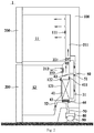
- Fig. 1 is a schematic view of a freezing and refrigerating device according to an embodiment of this invention.
- the freezing and refrigerating device 1 comprises a box body 100 and a door body 200 pivotably connected to the box body 100.
- Inside the box body 100 are defined: at least one storage compartment for storing articles, an air supply path, an air return path and a cooling chamber 40.
- the air supply path is configured to supply cooling air flow to the at least one storage compartment.
- the air return path is configured to allow the air flow from the at least one storage compartment to pass.
- the cooling chamber 40 communicates with the air supply path and the air return path, and contains an evaporator 41 for cooling the air entering the cooling chamber 40 from the air return path, a blower 42 for driving the air inside the cooling chamber 40 to flow towards the air supply path and a defrosting heater 43 provided on the evaporator.
- the box body 100 further defines an air discharging path 50 communicating with the cooling chamber 40 and an ambient space, so that the air in the cooling chamber 40 can be directly discharged to the ambient space.
- the air supply path and the air discharging path 50 are respectively provided therein with an air supply door and an air discharging door 51 respectively to selectively connect or block the air supply path and the air discharging path 50.
- the air supply path communicating with the cooling chamber 40 and the storage compartment is provided with an air supply door
- the air discharging path 50 communicating with the cooling chamber 40 and the ambient space is provided with an air discharging door 51
- the air supply door can block the air supply path, preventing the hot air generated when the defrosting heater 43 heats and defrosts from flowing into the storage compartment via the air supply path.
- the air discharging path 50 can be opened by the air discharging door 51, so that hot air generated by defrosting is directly discharged to the ambient space via the air discharging path 50.
- the freezing and refrigerating device 1 of this invention can prevent the temperature in the storage compartment from increasing due to the defrosting hot air, and extend the preservation time of food.
- the defrosting operations of the evaporator 41 hardly affect the temperature in the storage compartment. After the defrosting for the evaporator 41 ends, if refrigerating is performed to the storage compartment again, the temperature in the storage compartment can be restored to the temperature before the defrosting is performed in a short period, thereby reducing the energy consumption of the freezing and refrigerating device 1.
- one end of the air discharging path 50 communicating with the cooling chamber 40 is located downstream of the blower 42 in the air flowing direction.
- the blower 42 may continue working at a low power to drive the hot air generated by defrosting to be discharged to the ambient space via the air discharging path 50 located downstream of the blower 42, saving an additional driving member and simplifying the structure of the freezing and refrigerating device 1.
- the at least one storage compartment comprises a refrigerating compartment 11 and a freezing compartment 12 that are provided in a vertical direction relative to each other, and the cooling chamber 40 is located behind the freezing compartment 12 and is separated therefrom by a rear cover plate 121 of the freezing compartment 12.
- the air supply path comprises a refrigerating air feeding passage 211 located behind the refrigerating compartment 11 and a freezing air inlet 212 provided at the rear cover plate 121 of the freezing compartment 12, and the air supply door comprises a refrigerating air feeding door 221 provided inside the refrigerating air feeding passage 211 and a freezing air feeding door 222 provided at the freezing air inlet 212. That is, in the embodiments of this invention, the cooling chamber 40 communicates with the refrigerating compartment 11 and the freezing compartment 12 via the refrigerating air feeding passage 211 and the freezing air inlet 212 respectively.
- the cooling chamber 40 comprises an air feeding opening part communicating with the air supply path to supply cooling air flow to the at least one storage compartment via the air feeding opening part.
- the air feeding opening part comprises a refrigerating air feeding opening communicating with an air inlet end of the refrigerating air feeding passage 211 and a freezing air feeding opening communicating with the freezing air inlet 212.
- the refrigerating air feeding opening and the freezing air feeding opening are located downstream of the evaporator 41 in the air flowing direction to allow the air cooled by the evaporator 41 to pass.
- the refrigerating air feeding door 221 may be provided at the air inlet end of the refrigerating air feeding passage 211. Those skilled in the art shall understand that in other embodiments of this invention, the refrigerating air feeding door 221 may be provided at any position in the refrigerating air feeding passage 211, or at an air inlet of the refrigerating compartment 11.
- the air return passage may comprise a refrigerating air return passage 31 and a freezing air return passage 32.
- the air return opening part of the cooling chamber 40 may comprise a refrigerating air return opening communicating with the refrigerating air return passage 31 and a freezing air return opening communicating with the freezing air return passage 32.
- the air return opening part is located upstream of the evaporator 41 in the air flowing direction, or the refrigerating air return opening and the freezing air return opening are located upstream of the evaporator 41 in the air flowing direction, to guide the air from the refrigerating compartment 11 and the freezing compartment 12 to the evaporator 41 for cooling.
- the refrigerating air return passage 31 extends from the bottom of the refrigerating compartment 11 to the air return opening part of the cooling chamber 40.
- the refrigerating air return passage 31 is located behind the cooling chamber 40, and intersects with the air discharging path 50 communicating with the cooling chamber 40 and the ambient space.
- the air discharging door 51 is provided at an intersection of the refrigerating air return passage 31 and the air discharging path 50, such that when the air discharging door 51 is in a first state (a closed state), the refrigerating air return passage 31 is connected and the air discharging path 50 is blocked, and when the air discharging door 51 is in a second state (an opened state), the refrigerating air return passage 31 is blocked and the air discharging path 50 is connected.
- the air discharging door 51 can simultaneously control the connecting or blocking of the refrigerating air return passage 31 and the air discharging path 50, reducing the number of air doors and simplifying the structure of the freezing and refrigerating device 1 to some extent.
- a top of the evaporator 41 is provided with a first temperature sensor 411 to detect a temperature of the top of the evaporator 41.
- a first temperature sensor 411 to detect a temperature of the top of the evaporator 41.
- the defrosting heater 43 can be controlled automatically to stop heating the evaporator 41 based on the temperature data detected by the first temperature sensor 411 to realize smart control.
- rear cover plates of the refrigerating compartment 11 and the freezing compartment 12 may be provided with second and third temperature sensors 111, 122 to detect the temperatures in the refrigerating compartment 11 and the freezing compartment 12 respectively.
- the defrosting heater 43 may be provided on the bottom of the evaporator 41 and faces a groove 44 provided in the bottom of the cooling chamber 40, such that defrosting water generated during defrosting flows into a water collecting box 80 provided at the bottom of the box body 100 via a water discharging pipe 70 communicating with the groove 44.
- the water collecting box 80 is provided on a compressor 90. When the compressor 90 works, water in the water collecting box 80 is evaporated by the heat generated by the compressor.
- Fig. 2 is a schematic view of a freezing and refrigerating device in a refrigerating state according to an embodiment of this invention.
- the arrows in this figure represent the air flowing directions.
- the compressor 90, the evaporator 41 and the blower 42 are in operation states.
- the refrigerating air feeding door 221 and the freezing air feeding door 222 are opened to connect the refrigerating air feeding passage 211 and the freezing air inlet 212 respectively.
- the air flow cooled by the evaporator 41 sequentially passes the freezing air feeding opening, the air supply door and the air supply path of the cooling chamber 40, and flows into the storage compartment.
- the cooling air flow sequentially passes the refrigerating air feeding opening, the refrigerating air feeding door 221, the refrigerating air feeding passage 211 and the air inlet of the refrigerating compartment, and flows into the refrigerating compartment 11.
- the cooling air flow sequentially passes the freezing air feeding opening, the freezing air feeding door 222, the freezing air feeding inlet 212, and flows into the freezing compartment 12.
- the air in the storage compartment passes the air return path to return to the cooling chamber, is cooled by the evaporator 41 and flows into the storage compartment again. Thus, the air circulation path is formed.
- the air in the refrigerating compartment 11 passes the refrigerating air return passage 31 to return to the air return opening part of the cooling chamber 40, is cooled by the evaporator 41 and flows into the refrigerating compartment 11 again.
- the air circulation path in the refrigerating compartment 11 is formed.
- the air in the freezing compartment 12 passes the freezing air return passage 32 to return to the air return opening part of the cooling chamber 40, is cooled by the evaporator 41 and flows into the freezing compartment 12 again.
- the air circulation path in the freezing compartment 12 is formed.
- the air discharging door 51 is closed to block the air discharging path 50 and prevent the air flow cooled by the evaporator 41 from flowing to the ambient space.
- the freezing and refrigerating device 1 may control the refrigerating air feeding door 221 to close; when the third temperature sensor 122 detects that the temperature in the freezing compartment 12 reaches a third predetermined value, the freezing and refrigerating device 1 may control the freezing air feeding door 222 to close, thereby realizing automatic control of the cooling of the storage compartment.
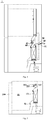
- Fig. 3 is a schematic view of a freezing and refrigerating device in a defrosting state according to an embodiment of this invention.
- the arrows in this figure represent the air flowing directions.
- the compressor 90 and the evaporator 41 are stopped.
- the defrosting heater 43 is started to heat the evaporator 41.
- the air discharging door 51 is opened, such that the hot air generated by defrosting is directly discharged to the ambient space via the air discharging path 50.
- the refrigerating air feeding door 221 and the freezing air feeding door 222 are closed to block the refrigerating air feeding passage 211 and the freezing air inlet 212, preventing the hot air generated by defrosting from entering the refrigerating compartment 11 and the freezing compartment 12 and avoiding influence to food preservation due to temperature fluctuations.
- the air in the ambient space may sequentially pass the water collecting box 80, the water discharging pipe 70 and the groove 44 to enter the cooling chamber 40, thereby forming an air circulation path when performing defrosting to the evaporator 41.
- the blower 42 may stop, and the hot air generated during defrosting may be discharged to the ambient space via the air discharging path 50 in a natural heat radiation manner.
- the blower 42 may work at a low power, so that the hot air generated during defrosting is discharged to the ambient space via the air discharging path 50 in a compulsory manner.
- Fig. 4 is a schematic view of a freezing and refrigerating device in an air discharging state according to another embodiment of this invention.
- the air discharging path 50 is provided with an air discharging pump 52 therein for driving the air in the cooling chamber 40 to flow towards the ambient space.
- One end of the air discharging path 50 communicating with the cooling chamber 40 may be located upstream or downstream of the blower 42 in the air flowing direction.
- the air discharging pump 52 may be started to drive the hot air generated during defrosting to be discharged to the ambient space via the air discharging path 50.
- the blower 42 may stop.
- Other structural features of the freezing and refrigerating device 1 in this embodiment of this invention are the same as those in the embodiment shown in Fig. 1 , and will not be repeated.
- Fig. 5 is a schematic view of a freezing and refrigerating device according to yet another embodiment of this invention.
- the at least one storage compartment comprises a freezing compartment 12, and the cooling chamber 40 is located behind the freezing compartment 12.
- the air supply path comprises a freezing air inlet 212 provided at the rear cover plate 121 of the freezing compartment 12.
- the air return path comprises a freezing air return passage 32 located at the bottom of the freezing compartment 12.
- the air supply door comprises a freezing air feeding door 222 provided at the freezing air inlet 212.
- Other structural features of the freezing and refrigerating device 1 in this embodiment of this invention are the same as those in the embodiment shown in Fig. 1 , and will not be repeated.
- Fig. 6 is a flow chart of a defrosting control method of a freezing and refrigerating device according to an embodiment of this invention.
- the defrosting control method comprises: step A: receiving a defrosting signal instructing the evaporator 41 of the freezing and refrigerating device 1 to perform defrosting; step B: starting the defrosting heater 43 located on the evaporator 41; step C: closing the air supply door located in the air supply path of the freezing and refrigerating device 1 to block the air supply path; and step D: opening the air discharging door 51 located in the air discharging path 50 of the freezing and refrigerating device 1 to connect the air discharging path 50, such that hot air generated by the defrosting heater 43 when performing heating and defrosting is directly discharged to the ambient space via the air discharging path 50.
- the air supply door may be closed, and then the air discharging door 51 is opened; or the air discharging door 51 is opened first, and then the air supply door is closed.
- Fig. 7 is a flow chart of a defrosting control method of a freezing and refrigerating device according to another embodiment of this invention.
- the method further comprises step E: starting the air discharging pump 52 in the air discharging path 50 to drive the hot air in the cooling chamber 40 to be discharged to the ambient space via the air discharging path 50.
- the blower may stop at this time, and only the air discharging pump 52 drives the air flow.
- the method further comprises step F: when the temperature of the top of the evaporator 41 reaches a first predetermined temperature, stopping the defrosting heater 43.
- the first temperature sensor 411 provided at the top of the evaporator 41 may detect the temperature of the top of the evaporator 41.
- the first predetermined temperature may be the temperature when defrosting for the evaporator 41 ends.
- the method further comprises step G: when the defrosting heater 43 is stopped for a predetermined time period, closing the air discharging pump 52 and the air discharging door 51.
- the hot air generated during defrosting of the evaporator 41 is basically completely discharged to the ambient space. Closing the air discharging pump 52 and the air discharging door 51 at this time can prevent excessive heat exchange between the air in the freezing and refrigerating device and the air in the ambient space, and improve the cooling performance of the freezing and refrigerating device.
- the freezing and refrigerating device 1 of this invention may be a fridge, a refrigerating cabinet, a wine cabinet, a refrigerating tank or other devices having a freezing or refrigerating function or having a freezing or refrigerating compartment.
Landscapes
- Engineering & Computer Science (AREA)
- Chemical & Material Sciences (AREA)
- Combustion & Propulsion (AREA)
- Physics & Mathematics (AREA)
- Mechanical Engineering (AREA)
- Thermal Sciences (AREA)
- General Engineering & Computer Science (AREA)
- Defrosting Systems (AREA)
- Cold Air Circulating Systems And Constructional Details In Refrigerators (AREA)
Abstract
Description
- The present invention is related to defrosting technologies of evaporators, and more particularly, to a freezing and refrigerating device and a defrosting control method thereof.
- Usually, after a freezing and refrigerating device, such as a fridge or the like, operates for a certain period, the surface of its evaporator frosts. The frost affects the heat exchange between the evaporator and the air inside the fridge and reduces the refrigerating efficiency of the evaporator. Therefore, defrosting must be performed after the fridge operates for a certain period.
- In the prior arts, usually defrosting of an evaporator is performed by heating. However, hot air generated during defrosting cannot be discharged out of the fridge. In this case, on one hand, the hot air may enter the storage compartment of the fridge via air inlets, and the temperature in the storage compartment rises, affecting the freshness and freezing time of food. On the other hand, after the defrosting for the evaporator ends, if refrigerating is performed to the storage compartment again, the temperature in the storage compartment can be restored to the temperature before the defrosting is performed after a long period, thereby increasing the energy consumption of the fridge.
- A first aspect of this invention aims to overcome at least one defect of existing freezing and refrigerating devices, and provides a freezing and refrigerating device. The freezing and refrigerating device of this invention can discharge the hot air generated by defrosting out of the freezing and refrigerating device, so that temperature rise in the storage compartment due to the defrosting hot air can be avoided, preservation time of food is extended and the energy consumption of the freezing and refrigerating device is reduced.
- A further object of the first aspect of this invention is to shorten the defrosting time of the freezing and refrigerating device to improve the defrosting effect.
- Another object of the first aspect of this invention is to automatically stop the defrosting for the evaporator.
- One object of a second aspect of this invention is to provide a defrosting control method of a freezing and refrigerating device.
- According to the first aspect of this invention, this invention provides a freezing and refrigerating device, comprising a box body and a door body pivotably connected to the box body, wherein inside the box body are defined: at least one storage compartment for storing articles; an air supply path configured to supply cooling air flow to the at least one storage compartment; an air return path configured to allow the air flow from the at least one storage compartment to pass; a cooling chamber which communicates with the air supply path and the air return path, and contains an evaporator for cooling the air entering the cooling chamber from the air return path, a blower for driving the air inside the cooling chamber to flow towards the air supply path and a defrosting heater provided on the evaporator; and an air discharging path communicating with the cooling chamber and an ambient space so that the air in the cooling chamber is directly discharged to the ambient space, wherein the air supply path and the air return path are respectively provided with an air supply door and an air discharging door for selectively connecting or blocking the air supply path and the air return path.
- Optionally, the air discharging path is provided with an air discharging pump therein for driving the air in the cooling chamber to flow towards the ambient space.
- Optionally, one end of the air discharging path communicating with the cooling chamber is located downstream of the blower in the air flowing direction.
- Optionally, the at least one storage compartment comprises a refrigerating compartment and a freezing compartment that are provided in a vertical direction relative to each other, and the cooling chamber is located behind the freezing compartment and is separated therefrom by a rear cover plate of the freezing compartment.
- Optionally, the air supply path comprises a refrigerating air feeding passage located behind the refrigerating compartment and a freezing air inlet provided at the rear cover plate of the freezing compartment, and the air supply door comprises a refrigerating air feeding door provided inside the refrigerating air feeding passage and a freezing air feeding door provided at the freezing air inlet.
- Optionally, the air return path comprises a refrigerating air return passage, which extends from the bottom of the refrigerating compartment to an air return opening part of the cooling chamber and intersects with the air discharging path; and the air discharging door is provided at an intersection of the refrigerating air return passage and the air discharging path, such that when the air discharging door is in a first state, the refrigerating air return passage is connected and the air discharging path is blocked, and when the air discharging door is in a second state, the refrigerating air return passage is blocked and the air discharging path is connected.
- Optionally, a top of the evaporator is provided with a first temperature sensor to detect a temperature of the top of the evaporator.
- Optionally, the defrosting heater is provided on the bottom of the evaporator and faces a groove provided in the bottom of the cooling chamber, such that defrosting water generated during defrosting flows into a water collecting box provided at the bottom of the box body via a water discharging pipe communicating with the groove.
- According to the second aspect of this invention, this invention also provides a defrosting control method of a freezing and refrigerating device, the method comprising: step A: receiving a defrosting signal instructing the evaporator of the freezing and refrigerating device to perform defrosting; step B: starting the defrosting heater located on the evaporator; step C: closing the air supply door located in the air supply path of the freezing and refrigerating device to block the air supply path; and step D: opening the air discharging door located in the air discharging path of the freezing and refrigerating device to connect the air discharging path, such that hot air generated by the defrosting heater when performing heating and defrosting is directly discharged to the ambient space via the air discharging path.
- Optionally, after the step A, the method further comprises step E: starting the air discharging pump in the air discharging path to drive the hot air in the cooling chamber to be discharged to the ambient space via the air discharging path.
- Optionally, after the step E, the method further comprises step F: when the temperature of the top of the evaporator reaches a first predetermined temperature, stopping the defrosting heater.
- Optionally, after the step F, the method further comprises step G: when the defrosting heater is stopped for a predetermined time period, closing the air discharging pump and the air discharging door.
- In the freezing and refrigerating device of this invention, as the air supply path communicating with the cooling chamber and the storage compartment is provided with an air supply door, and the air discharging path communicating with the cooling chamber and the ambient space is provided with an air discharging door, when defrosting is performed to the evaporator in the cooling chamber, the air supply door can block the air supply path, preventing the hot air generated when the defrosting heater heats and defrosts from flowing into the storage compartment via the air supply path. In addition, the air discharging path can be opened by the air discharging door, so that hot air generated by defrosting is directly discharged to the ambient space via the air discharging path. Therefore, the freezing and refrigerating device of this invention can prevent the temperature in the storage compartment from increasing due to the defrosting hot air, and extend the preservation time of food. In addition, the defrosting operations of the evaporator hardly affect the temperature in the storage compartment. After the defrosting for the evaporator ends, if refrigerating is performed to the storage compartment again, the temperature in the storage compartment can be restored to the temperature before the defrosting is performed in a short period, thereby reducing the energy consumption of the freezing and refrigerating device.
- Further, in the freezing and refrigerating device of this invention, as the air discharging path is provided with an air discharging pump therein for driving the air in the cooling chamber to flow towards the ambient space, the hot air generated by defrosting can be discharged in time, improving the air flow, shortening the defrosting time of the freezing and refrigerating device and improving the defrosting effect.
- Further, in the freezing and refrigerating device of this invention, as a top of the evaporator is provided with a first temperature sensor to detect a temperature of the top of the evaporator in real time, the defrosting condition can be determined. When the temperature of the top of the evaporator reaches a predetermined temperature, the defrosting heater is stopped, thereby automatically stopping the defrosting operations for the evaporator.
- The above and other objects, advantages and features of the invention will be understood by those skilled in the art more clearly with reference to the detailed description of the embodiments of this invention below with reference to the accompanying drawings.
- The followings will describe some embodiments of this invention in detail in an exemplary rather than restrictive manner with reference to the accompanying drawings. The same reference signs in the drawings represent the same or similar parts. Those skilled in the art shall understand that these drawings are only schematic ones of this invention, and may not be necessarily drawn according to the scales. In the drawings:
-
Fig. 1 is a schematic view of a freezing and refrigerating device according to an embodiment of this invention; -
Fig. 2 is a schematic view of a freezing and refrigerating device in a refrigerating state according to an embodiment of this invention; -
Fig. 3 is a schematic view of a freezing and refrigerating device in a defrosting state according to an embodiment of this invention; -
Fig. 4 is a schematic view of a freezing and refrigerating device according to another embodiment of this invention; -
Fig. 5 is a schematic view of a freezing and refrigerating device according to yet another embodiment of this invention; -
Fig. 6 is a flow chart of a defrosting control method of a freezing and refrigerating device according to an embodiment of this invention; and -
Fig. 7 is a flow chart of a defrosting control method of a freezing and refrigerating device according to another embodiment of this invention. -
Fig. 1 is a schematic view of a freezing and refrigerating device according to an embodiment of this invention. As shown inFig. 1 , the freezing and refrigeratingdevice 1 comprises abox body 100 and adoor body 200 pivotably connected to thebox body 100. Inside thebox body 100 are defined: at least one storage compartment for storing articles, an air supply path, an air return path and acooling chamber 40. The air supply path is configured to supply cooling air flow to the at least one storage compartment. The air return path is configured to allow the air flow from the at least one storage compartment to pass. Thecooling chamber 40 communicates with the air supply path and the air return path, and contains anevaporator 41 for cooling the air entering thecooling chamber 40 from the air return path, ablower 42 for driving the air inside thecooling chamber 40 to flow towards the air supply path and a defrostingheater 43 provided on the evaporator. In particular, thebox body 100 further defines anair discharging path 50 communicating with thecooling chamber 40 and an ambient space, so that the air in thecooling chamber 40 can be directly discharged to the ambient space. The air supply path and theair discharging path 50 are respectively provided therein with an air supply door and anair discharging door 51 respectively to selectively connect or block the air supply path and theair discharging path 50. - In the freezing and refrigerating
device 1 of this invention, as the air supply path communicating with thecooling chamber 40 and the storage compartment is provided with an air supply door, and theair discharging path 50 communicating with thecooling chamber 40 and the ambient space is provided with anair discharging door 51, when defrosting is performed to theevaporator 41 in thecooling chamber 40, the air supply door can block the air supply path, preventing the hot air generated when the defrostingheater 43 heats and defrosts from flowing into the storage compartment via the air supply path. In addition, theair discharging path 50 can be opened by theair discharging door 51, so that hot air generated by defrosting is directly discharged to the ambient space via theair discharging path 50. Therefore, the freezing and refrigeratingdevice 1 of this invention can prevent the temperature in the storage compartment from increasing due to the defrosting hot air, and extend the preservation time of food. In addition, the defrosting operations of theevaporator 41 hardly affect the temperature in the storage compartment. After the defrosting for theevaporator 41 ends, if refrigerating is performed to the storage compartment again, the temperature in the storage compartment can be restored to the temperature before the defrosting is performed in a short period, thereby reducing the energy consumption of the freezing and refrigeratingdevice 1. - In some embodiments of this invention, one end of the
air discharging path 50 communicating with thecooling chamber 40 is located downstream of theblower 42 in the air flowing direction. Thus, when theevaporator 41 needs defrosting, theblower 42 may continue working at a low power to drive the hot air generated by defrosting to be discharged to the ambient space via theair discharging path 50 located downstream of theblower 42, saving an additional driving member and simplifying the structure of the freezing and refrigeratingdevice 1. - In some embodiments of this invention, the at least one storage compartment comprises a
refrigerating compartment 11 and a freezingcompartment 12 that are provided in a vertical direction relative to each other, and the coolingchamber 40 is located behind the freezingcompartment 12 and is separated therefrom by arear cover plate 121 of the freezingcompartment 12. The air supply path comprises a refrigeratingair feeding passage 211 located behind therefrigerating compartment 11 and a freezingair inlet 212 provided at therear cover plate 121 of the freezingcompartment 12, and the air supply door comprises a refrigeratingair feeding door 221 provided inside the refrigeratingair feeding passage 211 and a freezingair feeding door 222 provided at the freezingair inlet 212. That is, in the embodiments of this invention, the coolingchamber 40 communicates with therefrigerating compartment 11 and the freezingcompartment 12 via the refrigeratingair feeding passage 211 and the freezingair inlet 212 respectively. - Further, the cooling
chamber 40 comprises an air feeding opening part communicating with the air supply path to supply cooling air flow to the at least one storage compartment via the air feeding opening part. Specifically, the air feeding opening part comprises a refrigerating air feeding opening communicating with an air inlet end of the refrigeratingair feeding passage 211 and a freezing air feeding opening communicating with the freezingair inlet 212. The refrigerating air feeding opening and the freezing air feeding opening are located downstream of theevaporator 41 in the air flowing direction to allow the air cooled by theevaporator 41 to pass. Further, the refrigeratingair feeding door 221 may be provided at the air inlet end of the refrigeratingair feeding passage 211. Those skilled in the art shall understand that in other embodiments of this invention, the refrigeratingair feeding door 221 may be provided at any position in the refrigeratingair feeding passage 211, or at an air inlet of therefrigerating compartment 11. - In some embodiments of this invention, the air return passage may comprise a refrigerating
air return passage 31 and a freezingair return passage 32. The air return opening part of the coolingchamber 40 may comprise a refrigerating air return opening communicating with the refrigeratingair return passage 31 and a freezing air return opening communicating with the freezingair return passage 32. The air return opening part is located upstream of theevaporator 41 in the air flowing direction, or the refrigerating air return opening and the freezing air return opening are located upstream of theevaporator 41 in the air flowing direction, to guide the air from the refrigeratingcompartment 11 and the freezingcompartment 12 to theevaporator 41 for cooling. The refrigeratingair return passage 31 extends from the bottom of therefrigerating compartment 11 to the air return opening part of the coolingchamber 40. - Further, the refrigerating
air return passage 31 is located behind the coolingchamber 40, and intersects with theair discharging path 50 communicating with the coolingchamber 40 and the ambient space. Theair discharging door 51 is provided at an intersection of the refrigeratingair return passage 31 and theair discharging path 50, such that when theair discharging door 51 is in a first state (a closed state), the refrigeratingair return passage 31 is connected and theair discharging path 50 is blocked, and when theair discharging door 51 is in a second state (an opened state), the refrigeratingair return passage 31 is blocked and theair discharging path 50 is connected. Thus, theair discharging door 51 can simultaneously control the connecting or blocking of the refrigeratingair return passage 31 and theair discharging path 50, reducing the number of air doors and simplifying the structure of the freezing and refrigeratingdevice 1 to some extent. - In some embodiments of this invention, a top of the
evaporator 41 is provided with afirst temperature sensor 411 to detect a temperature of the top of theevaporator 41. When the temperature of the top of theevaporator 41 reaches a first predetermined temperature, it is determined that defrosting of theevaporator 41 ends. Therefore, the defrostingheater 43 can be controlled automatically to stop heating theevaporator 41 based on the temperature data detected by thefirst temperature sensor 411 to realize smart control. - Further, rear cover plates of the
refrigerating compartment 11 and the freezingcompartment 12 may be provided with second andthird temperature sensors refrigerating compartment 11 and the freezingcompartment 12 respectively. - In some embodiments of this invention, the defrosting
heater 43 may be provided on the bottom of theevaporator 41 and faces agroove 44 provided in the bottom of the coolingchamber 40, such that defrosting water generated during defrosting flows into awater collecting box 80 provided at the bottom of thebox body 100 via awater discharging pipe 70 communicating with thegroove 44. Thewater collecting box 80 is provided on acompressor 90. When thecompressor 90 works, water in thewater collecting box 80 is evaporated by the heat generated by the compressor. -
Fig. 2 is a schematic view of a freezing and refrigerating device in a refrigerating state according to an embodiment of this invention. The arrows in this figure represent the air flowing directions. When the freezing and refrigeratingdevice 1 is in a refrigerating state, thecompressor 90, theevaporator 41 and theblower 42 are in operation states. The refrigeratingair feeding door 221 and the freezingair feeding door 222 are opened to connect the refrigeratingair feeding passage 211 and the freezingair inlet 212 respectively. The air flow cooled by the evaporator 41 sequentially passes the freezing air feeding opening, the air supply door and the air supply path of the coolingchamber 40, and flows into the storage compartment. That is, in this embodiment, the cooling air flow sequentially passes the refrigerating air feeding opening, the refrigeratingair feeding door 221, the refrigeratingair feeding passage 211 and the air inlet of the refrigerating compartment, and flows into therefrigerating compartment 11. The cooling air flow sequentially passes the freezing air feeding opening, the freezingair feeding door 222, the freezingair feeding inlet 212, and flows into the freezingcompartment 12. The air in the storage compartment passes the air return path to return to the cooling chamber, is cooled by theevaporator 41 and flows into the storage compartment again. Thus, the air circulation path is formed. That is, in this embodiment, the air in therefrigerating compartment 11 passes the refrigeratingair return passage 31 to return to the air return opening part of the coolingchamber 40, is cooled by theevaporator 41 and flows into therefrigerating compartment 11 again. Thus, the air circulation path in therefrigerating compartment 11 is formed. The air in the freezingcompartment 12 passes the freezingair return passage 32 to return to the air return opening part of the coolingchamber 40, is cooled by theevaporator 41 and flows into the freezingcompartment 12 again. Thus, the air circulation path in the freezingcompartment 12 is formed. In addition, theair discharging door 51 is closed to block theair discharging path 50 and prevent the air flow cooled by the evaporator 41 from flowing to the ambient space. - Further, when the
second temperature sensor 111 detects that the temperature in therefrigerating compartment 11 reaches a second predetermined value, the freezing and refrigeratingdevice 1 may control the refrigeratingair feeding door 221 to close; when thethird temperature sensor 122 detects that the temperature in the freezingcompartment 12 reaches a third predetermined value, the freezing and refrigeratingdevice 1 may control the freezingair feeding door 222 to close, thereby realizing automatic control of the cooling of the storage compartment. -
Fig. 3 is a schematic view of a freezing and refrigerating device in a defrosting state according to an embodiment of this invention. The arrows in this figure represent the air flowing directions. When the freezing and refrigeratingdevice 1 is in a defrosting state, thecompressor 90 and theevaporator 41 are stopped. The defrostingheater 43 is started to heat theevaporator 41. Theair discharging door 51 is opened, such that the hot air generated by defrosting is directly discharged to the ambient space via theair discharging path 50. The refrigeratingair feeding door 221 and the freezingair feeding door 222 are closed to block the refrigeratingair feeding passage 211 and the freezingair inlet 212, preventing the hot air generated by defrosting from entering therefrigerating compartment 11 and the freezingcompartment 12 and avoiding influence to food preservation due to temperature fluctuations. The air in the ambient space may sequentially pass thewater collecting box 80, thewater discharging pipe 70 and thegroove 44 to enter the coolingchamber 40, thereby forming an air circulation path when performing defrosting to theevaporator 41. Further, when performing defrosting to theevaporator 41, theblower 42 may stop, and the hot air generated during defrosting may be discharged to the ambient space via theair discharging path 50 in a natural heat radiation manner. Preferably, theblower 42 may work at a low power, so that the hot air generated during defrosting is discharged to the ambient space via theair discharging path 50 in a compulsory manner. -
Fig. 4 is a schematic view of a freezing and refrigerating device in an air discharging state according to another embodiment of this invention. In other embodiments of this invention, theair discharging path 50 is provided with anair discharging pump 52 therein for driving the air in the coolingchamber 40 to flow towards the ambient space. One end of theair discharging path 50 communicating with the coolingchamber 40 may be located upstream or downstream of theblower 42 in the air flowing direction. When theevaporator 41 needs defrosting, theair discharging pump 52 may be started to drive the hot air generated during defrosting to be discharged to the ambient space via theair discharging path 50. At this time, theblower 42 may stop. Other structural features of the freezing and refrigeratingdevice 1 in this embodiment of this invention are the same as those in the embodiment shown inFig. 1 , and will not be repeated. -
Fig. 5 is a schematic view of a freezing and refrigerating device according to yet another embodiment of this invention. In this embodiment of this invention, the at least one storage compartment comprises a freezingcompartment 12, and the coolingchamber 40 is located behind the freezingcompartment 12. The air supply path comprises a freezingair inlet 212 provided at therear cover plate 121 of the freezingcompartment 12. The air return path comprises a freezingair return passage 32 located at the bottom of the freezingcompartment 12. The air supply door comprises a freezingair feeding door 222 provided at the freezingair inlet 212. Other structural features of the freezing and refrigeratingdevice 1 in this embodiment of this invention are the same as those in the embodiment shown inFig. 1 , and will not be repeated. -
Fig. 6 is a flow chart of a defrosting control method of a freezing and refrigerating device according to an embodiment of this invention. In this embodiment, the defrosting control method comprises: step A: receiving a defrosting signal instructing theevaporator 41 of the freezing and refrigeratingdevice 1 to perform defrosting; step B: starting thedefrosting heater 43 located on theevaporator 41; step C: closing the air supply door located in the air supply path of the freezing and refrigeratingdevice 1 to block the air supply path; and step D: opening theair discharging door 51 located in theair discharging path 50 of the freezing and refrigeratingdevice 1 to connect theair discharging path 50, such that hot air generated by the defrostingheater 43 when performing heating and defrosting is directly discharged to the ambient space via theair discharging path 50. - Those skilled in the art shall understand that in this embodiment, there is no chronological order between the steps C and D. In other words, after starting the
defrosting heater 43, the air supply door may be closed, and then theair discharging door 51 is opened; or theair discharging door 51 is opened first, and then the air supply door is closed. -
Fig. 7 is a flow chart of a defrosting control method of a freezing and refrigerating device according to another embodiment of this invention. In other embodiments, after the step A, the method further comprises step E: starting theair discharging pump 52 in theair discharging path 50 to drive the hot air in the coolingchamber 40 to be discharged to the ambient space via theair discharging path 50. The blower may stop at this time, and only theair discharging pump 52 drives the air flow. Those skilled in the art shall understand that in this embodiment, there is no chronological order between the steps E and (C, D). In other words, the steps E and (C, D) may be performed in any order or simultaneously. - After the step E, the method further comprises step F: when the temperature of the top of the
evaporator 41 reaches a first predetermined temperature, stopping the defrostingheater 43. In this step, thefirst temperature sensor 411 provided at the top of theevaporator 41 may detect the temperature of the top of theevaporator 41. The first predetermined temperature may be the temperature when defrosting for theevaporator 41 ends. - Further, after the step F, the method further comprises step G: when the defrosting
heater 43 is stopped for a predetermined time period, closing theair discharging pump 52 and theair discharging door 51. When the defrostingheater 43 is stopped for a predetermined time period, the hot air generated during defrosting of theevaporator 41 is basically completely discharged to the ambient space. Closing theair discharging pump 52 and theair discharging door 51 at this time can prevent excessive heat exchange between the air in the freezing and refrigerating device and the air in the ambient space, and improve the cooling performance of the freezing and refrigerating device. - Those skilled in the art shall understand that the freezing and refrigerating
device 1 of this invention may be a fridge, a refrigerating cabinet, a wine cabinet, a refrigerating tank or other devices having a freezing or refrigerating function or having a freezing or refrigerating compartment. - Although multiple embodiments of this invention have been illustrated and described in detail, those skilled in the art may make various modifications and variations to the invention based on the content disclosed by this invention or the content derived therefrom without departing from the spirit and scope of the invention. Thus, the scope of this invention should be understood and deemed to include these and other modifications and variations.
Claims (12)
- A freezing and refrigerating device, comprising a box body and a door body pivotably connected to the box body, wherein inside the box body are defined:at least one storage compartment for storing articles;an air supply path configured to supply cooling air flow to the at least one storage compartment;an air return path configured to allow the air flow from the at least one storage compartment to pass;a cooling chamber which communicates with the air supply path and the air return path, and contains an evaporator for cooling the air entering the cooling chamber from the air return path, a blower for driving the air inside the cooling chamber to flow towards the air supply path and a defrosting heater provided on the evaporator; andan air discharging path communicating with the cooling chamber and an ambient space so that the air in the cooling chamber is directly discharged to the ambient space, whereinthe air supply path and the air return path are respectively provided with an air supply door and an air discharging door for selectively connecting or blocking the air supply path and the air return path.
- The freezing and refrigerating device of claim 1, wherein the air discharging path is provided with an air discharging pump therein for driving the air in the cooling chamber to flow towards the ambient space.
- The freezing and refrigerating device of claim 1, wherein one end of the air discharging path communicating with the cooling chamber is located downstream of the blower in the air flowing direction.
- The freezing and refrigerating device of claim 1, wherein the at least one storage compartment comprises a refrigerating compartment and a freezing compartment that are provided in a vertical direction relative to each other, and the cooling chamber is located behind the freezing compartment and is separated therefrom by a rear cover plate of the freezing compartment.
- The freezing and refrigerating device of claim 4, wherein the air supply path comprises a refrigerating air feeding passage located behind the refrigerating compartment and a freezing air inlet provided at the rear cover plate of the freezing compartment, and the air supply door comprises a refrigerating air feeding door provided inside the refrigerating air feeding passage and a freezing air feeding door provided at the freezing air inlet.
- The freezing and refrigerating device of claim 4, wherein the air return path comprises a refrigerating air return passage, which extends from the bottom of the refrigerating compartment to an air return opening part of the cooling chamber and intersects with the air discharging path; and
the air discharging door is provided at an intersection of the refrigerating air return passage and the air discharging path, such that when the air discharging door is in a first state, the refrigerating air return passage is connected and the air discharging path is blocked, and when the air discharging door is in a second state, the refrigerating air return passage is blocked and the air discharging path is connected. - The freezing and refrigerating device of claim 1, wherein a top of the evaporator is provided with a first temperature sensor to detect a temperature of the top of the evaporator.
- The freezing and refrigerating device of claim 1, wherein the defrosting heater is provided on the bottom of the evaporator and faces a groove provided in the bottom of the cooling chamber, such that defrosting water generated during defrosting flows into a water collecting box provided at the bottom of the box body via a water discharging pipe communicating with the groove.
- A defrosting control method of a freezing and refrigerating device of any of claims 1-8, the method comprising:step A: receiving a defrosting signal instructing the evaporator of the freezing and refrigerating device to perform defrosting;step B: starting the defrosting heater located on the evaporator;step C: closing the air supply door located in the air supply path of the freezing and refrigerating device to block the air supply path; andstep D: opening the air discharging door located in the air discharging path of the freezing and refrigerating device to connect the air discharging path, such that hot air generated by the defrosting heater when performing heating and defrosting is directly discharged to the ambient space via the air discharging path.
- The defrosting control method of claim 9, after the step A, further comprising: step E: starting the air discharging pump in the air discharging path to drive the hot air in the cooling chamber to be discharged to the ambient space via the air discharging path.
- The defrosting control method of claim 10, after the step E, further comprising: step F: when the temperature of the top of the evaporator reaches a first predetermined temperature, stopping the defrosting heater.
- The defrosting control method of claim 11, after the step F, further comprising: step G: when the defrosting heater is stopped for a predetermined time period, closing the air discharging pump and the air discharging door.
Applications Claiming Priority (2)
| Application Number | Priority Date | Filing Date | Title |
|---|---|---|---|
| CN201510213293.6A CN104807279B (en) | 2015-04-29 | 2015-04-29 | A kind of fridge-freezer and its defrosting control method |
| PCT/CN2015/093402 WO2016173226A1 (en) | 2015-04-29 | 2015-10-30 | Freezing and refrigerating device and defrosting control method thereof |
Publications (3)
| Publication Number | Publication Date |
|---|---|
| EP3290836A1 true EP3290836A1 (en) | 2018-03-07 |
| EP3290836A4 EP3290836A4 (en) | 2018-07-25 |
| EP3290836B1 EP3290836B1 (en) | 2020-09-30 |
Family
ID=53692328
Family Applications (1)
| Application Number | Title | Priority Date | Filing Date |
|---|---|---|---|
| EP15890601.6A Active EP3290836B1 (en) | 2015-04-29 | 2015-10-30 | Freezing and refrigerating device and defrosting control method thereof |
Country Status (4)
| Country | Link |
|---|---|
| US (1) | US20170241696A1 (en) |
| EP (1) | EP3290836B1 (en) |
| CN (1) | CN104807279B (en) |
| WO (1) | WO2016173226A1 (en) |
Families Citing this family (23)
| Publication number | Priority date | Publication date | Assignee | Title |
|---|---|---|---|---|
| CN104792094B (en) * | 2015-04-29 | 2018-02-02 | 青岛海尔股份有限公司 | A kind of fridge-freezer and its defrosting control method |
| CN104807279B (en) * | 2015-04-29 | 2019-01-18 | 青岛海尔股份有限公司 | A kind of fridge-freezer and its defrosting control method |
| DE102015221667A1 (en) * | 2015-11-04 | 2017-05-04 | BSH Hausgeräte GmbH | Refrigeration unit with flexible compartment |
| CN105466117B (en) * | 2015-11-19 | 2018-02-02 | 青岛海尔股份有限公司 | A kind of fridge-freezer |
| US10612832B2 (en) * | 2015-12-17 | 2020-04-07 | Samsung Electronics Co., Ltd. | Refrigerator with defrost operation control |
| CN106016955A (en) * | 2016-06-06 | 2016-10-12 | 许昌学院 | Intelligent refrigerator controller and control method |
| CN107449189A (en) * | 2017-08-30 | 2017-12-08 | 天津大学 | A kind of quick vacuum cooling unit and cooling means for eliminating evaporator defrosting waste heat |
| CN108613452B (en) * | 2017-12-29 | 2023-11-10 | 青岛海尔特种电冰柜有限公司 | Air-cooled refrigeration equipment and control method thereof |
| CN110068187A (en) * | 2019-04-11 | 2019-07-30 | 安徽康佳同创电器有限公司 | A kind of refrigerator |
| CN111137564B (en) * | 2019-12-25 | 2021-10-19 | 华南农业大学 | Frost prevention system for cold storage plate for fresh-keeping transport case and control method |
| CN113074491A (en) * | 2020-01-03 | 2021-07-06 | 青岛海尔智能技术研发有限公司 | Air-cooled refrigerator |
| CN113074481B (en) * | 2020-01-06 | 2024-01-12 | 博西华电器(江苏)有限公司 | Refrigerator control method and refrigerator |
| CN113701445A (en) * | 2020-05-22 | 2021-11-26 | 青岛海尔电冰箱有限公司 | Control method of refrigerating and freezing device |
| CN113701428A (en) * | 2020-05-22 | 2021-11-26 | 青岛海尔电冰箱有限公司 | Control method of dual-system refrigerator |
| CN113701444A (en) * | 2020-05-22 | 2021-11-26 | 青岛海尔电冰箱有限公司 | Control method of refrigerating and freezing device |
| CN113701427A (en) * | 2020-05-22 | 2021-11-26 | 青岛海尔电冰箱有限公司 | Control method of dual-system refrigerator |
| CN112665279B (en) * | 2020-12-23 | 2022-04-12 | 珠海格力电器股份有限公司 | Exhaust mechanism, refrigerator and exhaust control method of refrigerator |
| CN113720077B (en) * | 2021-09-03 | 2023-05-16 | 青岛海尔电冰箱有限公司 | Air-cooled refrigeration equipment |
| CN113776255A (en) * | 2021-10-09 | 2021-12-10 | 北京云迹科技有限公司 | Refrigeration cabinet and refrigeration system |
| CN114034157B (en) * | 2021-11-26 | 2022-11-11 | 澳柯玛股份有限公司 | But vertical transparent door hutch of air-cooled of cold and hot conversion |
| JP2023095340A (en) * | 2021-12-24 | 2023-07-06 | アクア株式会社 | refrigerator |
| CN114659322B (en) * | 2022-03-14 | 2023-10-24 | 重庆海尔制冷电器有限公司 | Air-cooled refrigerator |
| CN115342590B (en) * | 2022-08-01 | 2024-02-20 | 华东医药供应链管理(杭州)有限公司 | Intelligent control device for defrosting waste heat of air cooler of vaccine ultralow-temperature warehouse and control method of intelligent control device |
Family Cites Families (21)
| Publication number | Priority date | Publication date | Assignee | Title |
|---|---|---|---|---|
| DE2841804A1 (en) * | 1978-09-26 | 1980-04-03 | Sachs Systemtechnik Gmbh | Heat pump for central heating - has refrigerator circuit with evaporator in air duct, with exhaust fan and heater |
| DE4407382A1 (en) * | 1994-03-05 | 1995-09-07 | Gerhard Plueschau Ohg Kaelte K | Refrigerating device |
| KR100203983B1 (en) * | 1995-04-06 | 1999-06-15 | 전주범 | Refrigerator |
| KR970022095A (en) * | 1995-10-31 | 1997-05-28 | 배순훈 | Quick freezer freezer |
| KR19990005704A (en) * | 1997-06-30 | 1999-01-25 | 배순훈 | Defroster of the refrigerator |
| US6629422B2 (en) * | 2001-06-07 | 2003-10-07 | Keith E. Wellman | Sequential defrosting of refrigerated display cases |
| CN1176341C (en) * | 2002-01-29 | 2004-11-17 | 乐金电子(天津)电器有限公司 | Defrosting device for evaporator of electric refrigerator |
| KR100549073B1 (en) * | 2003-12-11 | 2006-02-06 | 삼성전자주식회사 | Refrigerator and method of controlling the same |
| KR101328959B1 (en) * | 2007-11-05 | 2013-11-14 | 엘지전자 주식회사 | food storaging apparatus |
| KR20100085228A (en) * | 2009-01-20 | 2010-07-29 | 주식회사 대우일렉트로닉스 | Defrosting apparatus of refrigerator |
| CN103017267B (en) * | 2009-03-27 | 2015-09-30 | 三菱电机株式会社 | Air regulator |
| CN102997534B (en) * | 2011-09-13 | 2015-11-04 | 珠海格力电器股份有限公司 | Refrigerator and defrosting method thereof |
| US9310121B2 (en) * | 2011-10-19 | 2016-04-12 | Thermo Fisher Scientific (Asheville) Llc | High performance refrigerator having sacrificial evaporator |
| DE102012020106A1 (en) * | 2011-10-19 | 2013-04-25 | Thermo Fisher Scientific (Asheville) LLC (n. d. Ges. d. Staates Delaware) | HIGH-PERFORMANCE COOLER WITH EVAPORIZER OUTSIDE OF THE CABINET |
| US8997507B2 (en) * | 2012-10-22 | 2015-04-07 | Whirlpool Corporation | Low energy evaporator defrost |
| CN104279812A (en) * | 2013-07-05 | 2015-01-14 | 海尔集团公司 | Refrigeration device and defrosting method thereof |
| CN103868309B (en) * | 2014-03-19 | 2016-04-13 | 天津大学 | The device utilizing freezer outside air auxiliary electrical heater to defrost and the method for operation thereof |
| CN104807279B (en) * | 2015-04-29 | 2019-01-18 | 青岛海尔股份有限公司 | A kind of fridge-freezer and its defrosting control method |
| CN104792094B (en) * | 2015-04-29 | 2018-02-02 | 青岛海尔股份有限公司 | A kind of fridge-freezer and its defrosting control method |
| CN204678774U (en) * | 2015-04-29 | 2015-09-30 | 青岛海尔股份有限公司 | A kind of fridge-freezer |
| CN204678776U (en) * | 2015-04-29 | 2015-09-30 | 青岛海尔股份有限公司 | A kind of fridge-freezer |
-
2015
- 2015-04-29 CN CN201510213293.6A patent/CN104807279B/en active Active
- 2015-10-30 US US15/523,335 patent/US20170241696A1/en not_active Abandoned
- 2015-10-30 WO PCT/CN2015/093402 patent/WO2016173226A1/en active Application Filing
- 2015-10-30 EP EP15890601.6A patent/EP3290836B1/en active Active
Also Published As
| Publication number | Publication date |
|---|---|
| CN104807279B (en) | 2019-01-18 |
| WO2016173226A1 (en) | 2016-11-03 |
| US20170241696A1 (en) | 2017-08-24 |
| CN104807279A (en) | 2015-07-29 |
| EP3290836B1 (en) | 2020-09-30 |
| EP3290836A4 (en) | 2018-07-25 |
Similar Documents
| Publication | Publication Date | Title |
|---|---|---|
| EP3290836B1 (en) | Freezing and refrigerating device and defrosting control method thereof | |
| EP3290837B1 (en) | Freezing and cold storage device and defrosting control method therefor | |
| US9243834B2 (en) | Refrigerator | |
| CN106247742B (en) | A kind of refrigerator freezing fan defrosting device and its control method | |
| US10054358B2 (en) | Refrigerator and method of operating the same | |
| CN106196843A (en) | Wind cooling refrigerator and dehumanization method thereof | |
| AU2012327214A1 (en) | Vending machine | |
| KR101771721B1 (en) | Refrigerator and its defrost control method | |
| KR101269068B1 (en) | Controll method middle and small sized cold storage room | |
| CN204678774U (en) | A kind of fridge-freezer | |
| KR102641371B1 (en) | Refrigerator | |
| JP2019039586A (en) | refrigerator | |
| CN204678776U (en) | A kind of fridge-freezer | |
| EP4067795A1 (en) | Air cooling device control method and air cooling device | |
| US20180135902A1 (en) | Refrigerant circuit device | |
| KR101811496B1 (en) | Refrigerator and control method thereof | |
| JP6020034B2 (en) | Vending machine cooling system | |
| CN105650981A (en) | Refrigerator | |
| CN109737656B (en) | Ice maker, defrosting control method thereof and refrigerator | |
| CN110425787A (en) | Use for electric locomotive intelligent thermoregulating cold storage plant and its method for regulating temperature | |
| CN220507387U (en) | Refrigerator with a refrigerator body | |
| US20240011697A1 (en) | Refrigerator | |
| CN105651000A (en) | Refrigeration equipment and defrosting control method | |
| CN115727591A (en) | Refrigerating and freezing device | |
| KR101072449B1 (en) | Independent temperature control apparatus for the vegetable room of a side by side type refrigerator |
Legal Events
| Date | Code | Title | Description |
|---|---|---|---|
| STAA | Information on the status of an ep patent application or granted ep patent |
Free format text: STATUS: THE INTERNATIONAL PUBLICATION HAS BEEN MADE |
|
| PUAI | Public reference made under article 153(3) epc to a published international application that has entered the european phase |
Free format text: ORIGINAL CODE: 0009012 |
|
| STAA | Information on the status of an ep patent application or granted ep patent |
Free format text: STATUS: REQUEST FOR EXAMINATION WAS MADE |
|
| 17P | Request for examination filed |
Effective date: 20170529 |
|
| AK | Designated contracting states |
Kind code of ref document: A1 Designated state(s): AL AT BE BG CH CY CZ DE DK EE ES FI FR GB GR HR HU IE IS IT LI LT LU LV MC MK MT NL NO PL PT RO RS SE SI SK SM TR |
|
| AX | Request for extension of the european patent |
Extension state: BA ME |
|
| A4 | Supplementary search report drawn up and despatched |
Effective date: 20180625 |
|
| RIC1 | Information provided on ipc code assigned before grant |
Ipc: F25D 21/06 20060101AFI20180619BHEP Ipc: F25D 21/12 20060101ALI20180619BHEP |
|
| DAV | Request for validation of the european patent (deleted) | ||
| DAX | Request for extension of the european patent (deleted) | ||
| GRAP | Despatch of communication of intention to grant a patent |
Free format text: ORIGINAL CODE: EPIDOSNIGR1 |
|
| STAA | Information on the status of an ep patent application or granted ep patent |
Free format text: STATUS: GRANT OF PATENT IS INTENDED |
|
| INTG | Intention to grant announced |
Effective date: 20200417 |
|
| GRAS | Grant fee paid |
Free format text: ORIGINAL CODE: EPIDOSNIGR3 |
|
| GRAA | (expected) grant |
Free format text: ORIGINAL CODE: 0009210 |
|
| STAA | Information on the status of an ep patent application or granted ep patent |
Free format text: STATUS: THE PATENT HAS BEEN GRANTED |
|
| AK | Designated contracting states |
Kind code of ref document: B1 Designated state(s): AL AT BE BG CH CY CZ DE DK EE ES FI FR GB GR HR HU IE IS IT LI LT LU LV MC MK MT NL NO PL PT RO RS SE SI SK SM TR |
|
| REG | Reference to a national code |
Ref country code: CH Ref legal event code: EP Ref country code: GB Ref legal event code: FG4D |
|
| REG | Reference to a national code |
Ref country code: AT Ref legal event code: REF Ref document number: 1319214 Country of ref document: AT Kind code of ref document: T Effective date: 20201015 |
|
| REG | Reference to a national code |
Ref country code: DE Ref legal event code: R096 Ref document number: 602015059985 Country of ref document: DE |
|
| REG | Reference to a national code |
Ref country code: IE Ref legal event code: FG4D |
|
| PG25 | Lapsed in a contracting state [announced via postgrant information from national office to epo] |
Ref country code: GR Free format text: LAPSE BECAUSE OF FAILURE TO SUBMIT A TRANSLATION OF THE DESCRIPTION OR TO PAY THE FEE WITHIN THE PRESCRIBED TIME-LIMIT Effective date: 20201231 Ref country code: NO Free format text: LAPSE BECAUSE OF FAILURE TO SUBMIT A TRANSLATION OF THE DESCRIPTION OR TO PAY THE FEE WITHIN THE PRESCRIBED TIME-LIMIT Effective date: 20201230 Ref country code: BG Free format text: LAPSE BECAUSE OF FAILURE TO SUBMIT A TRANSLATION OF THE DESCRIPTION OR TO PAY THE FEE WITHIN THE PRESCRIBED TIME-LIMIT Effective date: 20201230 Ref country code: SE Free format text: LAPSE BECAUSE OF FAILURE TO SUBMIT A TRANSLATION OF THE DESCRIPTION OR TO PAY THE FEE WITHIN THE PRESCRIBED TIME-LIMIT Effective date: 20200930 Ref country code: FI Free format text: LAPSE BECAUSE OF FAILURE TO SUBMIT A TRANSLATION OF THE DESCRIPTION OR TO PAY THE FEE WITHIN THE PRESCRIBED TIME-LIMIT Effective date: 20200930 Ref country code: HR Free format text: LAPSE BECAUSE OF FAILURE TO SUBMIT A TRANSLATION OF THE DESCRIPTION OR TO PAY THE FEE WITHIN THE PRESCRIBED TIME-LIMIT Effective date: 20200930 |
|
| REG | Reference to a national code |
Ref country code: AT Ref legal event code: MK05 Ref document number: 1319214 Country of ref document: AT Kind code of ref document: T Effective date: 20200930 |
|
| PG25 | Lapsed in a contracting state [announced via postgrant information from national office to epo] |
Ref country code: LV Free format text: LAPSE BECAUSE OF FAILURE TO SUBMIT A TRANSLATION OF THE DESCRIPTION OR TO PAY THE FEE WITHIN THE PRESCRIBED TIME-LIMIT Effective date: 20200930 Ref country code: RS Free format text: LAPSE BECAUSE OF FAILURE TO SUBMIT A TRANSLATION OF THE DESCRIPTION OR TO PAY THE FEE WITHIN THE PRESCRIBED TIME-LIMIT Effective date: 20200930 |
|
| REG | Reference to a national code |
Ref country code: NL Ref legal event code: MP Effective date: 20200930 |
|
| REG | Reference to a national code |
Ref country code: LT Ref legal event code: MG4D |
|
| PG25 | Lapsed in a contracting state [announced via postgrant information from national office to epo] |
Ref country code: SM Free format text: LAPSE BECAUSE OF FAILURE TO SUBMIT A TRANSLATION OF THE DESCRIPTION OR TO PAY THE FEE WITHIN THE PRESCRIBED TIME-LIMIT Effective date: 20200930 Ref country code: RO Free format text: LAPSE BECAUSE OF FAILURE TO SUBMIT A TRANSLATION OF THE DESCRIPTION OR TO PAY THE FEE WITHIN THE PRESCRIBED TIME-LIMIT Effective date: 20200930 Ref country code: PT Free format text: LAPSE BECAUSE OF FAILURE TO SUBMIT A TRANSLATION OF THE DESCRIPTION OR TO PAY THE FEE WITHIN THE PRESCRIBED TIME-LIMIT Effective date: 20210201 Ref country code: EE Free format text: LAPSE BECAUSE OF FAILURE TO SUBMIT A TRANSLATION OF THE DESCRIPTION OR TO PAY THE FEE WITHIN THE PRESCRIBED TIME-LIMIT Effective date: 20200930 Ref country code: NL Free format text: LAPSE BECAUSE OF FAILURE TO SUBMIT A TRANSLATION OF THE DESCRIPTION OR TO PAY THE FEE WITHIN THE PRESCRIBED TIME-LIMIT Effective date: 20200930 Ref country code: LT Free format text: LAPSE BECAUSE OF FAILURE TO SUBMIT A TRANSLATION OF THE DESCRIPTION OR TO PAY THE FEE WITHIN THE PRESCRIBED TIME-LIMIT Effective date: 20200930 Ref country code: CZ Free format text: LAPSE BECAUSE OF FAILURE TO SUBMIT A TRANSLATION OF THE DESCRIPTION OR TO PAY THE FEE WITHIN THE PRESCRIBED TIME-LIMIT Effective date: 20200930 |
|
| PG25 | Lapsed in a contracting state [announced via postgrant information from national office to epo] |
Ref country code: ES Free format text: LAPSE BECAUSE OF FAILURE TO SUBMIT A TRANSLATION OF THE DESCRIPTION OR TO PAY THE FEE WITHIN THE PRESCRIBED TIME-LIMIT Effective date: 20200930 Ref country code: AT Free format text: LAPSE BECAUSE OF FAILURE TO SUBMIT A TRANSLATION OF THE DESCRIPTION OR TO PAY THE FEE WITHIN THE PRESCRIBED TIME-LIMIT Effective date: 20200930 Ref country code: AL Free format text: LAPSE BECAUSE OF FAILURE TO SUBMIT A TRANSLATION OF THE DESCRIPTION OR TO PAY THE FEE WITHIN THE PRESCRIBED TIME-LIMIT Effective date: 20200930 Ref country code: PL Free format text: LAPSE BECAUSE OF FAILURE TO SUBMIT A TRANSLATION OF THE DESCRIPTION OR TO PAY THE FEE WITHIN THE PRESCRIBED TIME-LIMIT Effective date: 20200930 Ref country code: IS Free format text: LAPSE BECAUSE OF FAILURE TO SUBMIT A TRANSLATION OF THE DESCRIPTION OR TO PAY THE FEE WITHIN THE PRESCRIBED TIME-LIMIT Effective date: 20210130 |
|
| REG | Reference to a national code |
Ref country code: CH Ref legal event code: PL |
|
| PG25 | Lapsed in a contracting state [announced via postgrant information from national office to epo] |
Ref country code: LU Free format text: LAPSE BECAUSE OF NON-PAYMENT OF DUE FEES Effective date: 20201030 Ref country code: MC Free format text: LAPSE BECAUSE OF FAILURE TO SUBMIT A TRANSLATION OF THE DESCRIPTION OR TO PAY THE FEE WITHIN THE PRESCRIBED TIME-LIMIT Effective date: 20200930 Ref country code: SK Free format text: LAPSE BECAUSE OF FAILURE TO SUBMIT A TRANSLATION OF THE DESCRIPTION OR TO PAY THE FEE WITHIN THE PRESCRIBED TIME-LIMIT Effective date: 20200930 |
|
| REG | Reference to a national code |
Ref country code: DE Ref legal event code: R097 Ref document number: 602015059985 Country of ref document: DE |
|
| REG | Reference to a national code |
Ref country code: BE Ref legal event code: MM Effective date: 20201031 |
|
| PLBE | No opposition filed within time limit |
Free format text: ORIGINAL CODE: 0009261 |
|
| STAA | Information on the status of an ep patent application or granted ep patent |
Free format text: STATUS: NO OPPOSITION FILED WITHIN TIME LIMIT |
|
| PG25 | Lapsed in a contracting state [announced via postgrant information from national office to epo] |
Ref country code: LI Free format text: LAPSE BECAUSE OF NON-PAYMENT OF DUE FEES Effective date: 20201031 Ref country code: BE Free format text: LAPSE BECAUSE OF NON-PAYMENT OF DUE FEES Effective date: 20201031 Ref country code: CH Free format text: LAPSE BECAUSE OF NON-PAYMENT OF DUE FEES Effective date: 20201031 Ref country code: DK Free format text: LAPSE BECAUSE OF FAILURE TO SUBMIT A TRANSLATION OF THE DESCRIPTION OR TO PAY THE FEE WITHIN THE PRESCRIBED TIME-LIMIT Effective date: 20200930 |
|
| 26N | No opposition filed |
Effective date: 20210701 |
|
| PG25 | Lapsed in a contracting state [announced via postgrant information from national office to epo] |
Ref country code: IE Free format text: LAPSE BECAUSE OF NON-PAYMENT OF DUE FEES Effective date: 20201030 Ref country code: IT Free format text: LAPSE BECAUSE OF FAILURE TO SUBMIT A TRANSLATION OF THE DESCRIPTION OR TO PAY THE FEE WITHIN THE PRESCRIBED TIME-LIMIT Effective date: 20200930 |
|
| PG25 | Lapsed in a contracting state [announced via postgrant information from national office to epo] |
Ref country code: SI Free format text: LAPSE BECAUSE OF FAILURE TO SUBMIT A TRANSLATION OF THE DESCRIPTION OR TO PAY THE FEE WITHIN THE PRESCRIBED TIME-LIMIT Effective date: 20200930 |
|
| PG25 | Lapsed in a contracting state [announced via postgrant information from national office to epo] |
Ref country code: IS Free format text: LAPSE BECAUSE OF FAILURE TO SUBMIT A TRANSLATION OF THE DESCRIPTION OR TO PAY THE FEE WITHIN THE PRESCRIBED TIME-LIMIT Effective date: 20210130 Ref country code: TR Free format text: LAPSE BECAUSE OF FAILURE TO SUBMIT A TRANSLATION OF THE DESCRIPTION OR TO PAY THE FEE WITHIN THE PRESCRIBED TIME-LIMIT Effective date: 20200930 Ref country code: MT Free format text: LAPSE BECAUSE OF FAILURE TO SUBMIT A TRANSLATION OF THE DESCRIPTION OR TO PAY THE FEE WITHIN THE PRESCRIBED TIME-LIMIT Effective date: 20200930 Ref country code: CY Free format text: LAPSE BECAUSE OF FAILURE TO SUBMIT A TRANSLATION OF THE DESCRIPTION OR TO PAY THE FEE WITHIN THE PRESCRIBED TIME-LIMIT Effective date: 20200930 |
|
| PG25 | Lapsed in a contracting state [announced via postgrant information from national office to epo] |
Ref country code: MK Free format text: LAPSE BECAUSE OF FAILURE TO SUBMIT A TRANSLATION OF THE DESCRIPTION OR TO PAY THE FEE WITHIN THE PRESCRIBED TIME-LIMIT Effective date: 20200930 |
|
| PGFP | Annual fee paid to national office [announced via postgrant information from national office to epo] |
Ref country code: GB Payment date: 20231019 Year of fee payment: 9 |
|
| PGFP | Annual fee paid to national office [announced via postgrant information from national office to epo] |
Ref country code: FR Payment date: 20231023 Year of fee payment: 9 Ref country code: DE Payment date: 20231011 Year of fee payment: 9 |