EP3290787A1 - A lighting device and corresponding method - Google Patents
A lighting device and corresponding method Download PDFInfo
- Publication number
- EP3290787A1 EP3290787A1 EP17186384.8A EP17186384A EP3290787A1 EP 3290787 A1 EP3290787 A1 EP 3290787A1 EP 17186384 A EP17186384 A EP 17186384A EP 3290787 A1 EP3290787 A1 EP 3290787A1
- Authority
- EP
- European Patent Office
- Prior art keywords
- lighting
- driver
- seat
- lighting device
- impedance
- Prior art date
- Legal status (The legal status is an assumption and is not a legal conclusion. Google has not performed a legal analysis and makes no representation as to the accuracy of the status listed.)
- Granted
Links
Images


Classifications
-
- H—ELECTRICITY
- H05—ELECTRIC TECHNIQUES NOT OTHERWISE PROVIDED FOR
- H05B—ELECTRIC HEATING; ELECTRIC LIGHT SOURCES NOT OTHERWISE PROVIDED FOR; CIRCUIT ARRANGEMENTS FOR ELECTRIC LIGHT SOURCES, IN GENERAL
- H05B45/00—Circuit arrangements for operating light-emitting diodes [LED]
- H05B45/10—Controlling the intensity of the light
-
- F—MECHANICAL ENGINEERING; LIGHTING; HEATING; WEAPONS; BLASTING
- F21—LIGHTING
- F21S—NON-PORTABLE LIGHTING DEVICES; SYSTEMS THEREOF; VEHICLE LIGHTING DEVICES SPECIALLY ADAPTED FOR VEHICLE EXTERIORS
- F21S4/00—Lighting devices or systems using a string or strip of light sources
- F21S4/20—Lighting devices or systems using a string or strip of light sources with light sources held by or within elongate supports
-
- F—MECHANICAL ENGINEERING; LIGHTING; HEATING; WEAPONS; BLASTING
- F21—LIGHTING
- F21V—FUNCTIONAL FEATURES OR DETAILS OF LIGHTING DEVICES OR SYSTEMS THEREOF; STRUCTURAL COMBINATIONS OF LIGHTING DEVICES WITH OTHER ARTICLES, NOT OTHERWISE PROVIDED FOR
- F21V23/00—Arrangement of electric circuit elements in or on lighting devices
- F21V23/003—Arrangement of electric circuit elements in or on lighting devices the elements being electronics drivers or controllers for operating the light source, e.g. for a LED array
-
- F—MECHANICAL ENGINEERING; LIGHTING; HEATING; WEAPONS; BLASTING
- F21—LIGHTING
- F21V—FUNCTIONAL FEATURES OR DETAILS OF LIGHTING DEVICES OR SYSTEMS THEREOF; STRUCTURAL COMBINATIONS OF LIGHTING DEVICES WITH OTHER ARTICLES, NOT OTHERWISE PROVIDED FOR
- F21V23/00—Arrangement of electric circuit elements in or on lighting devices
- F21V23/003—Arrangement of electric circuit elements in or on lighting devices the elements being electronics drivers or controllers for operating the light source, e.g. for a LED array
- F21V23/004—Arrangement of electric circuit elements in or on lighting devices the elements being electronics drivers or controllers for operating the light source, e.g. for a LED array arranged on a substrate, e.g. a printed circuit board
- F21V23/005—Arrangement of electric circuit elements in or on lighting devices the elements being electronics drivers or controllers for operating the light source, e.g. for a LED array arranged on a substrate, e.g. a printed circuit board the substrate is supporting also the light source
-
- F—MECHANICAL ENGINEERING; LIGHTING; HEATING; WEAPONS; BLASTING
- F21—LIGHTING
- F21V—FUNCTIONAL FEATURES OR DETAILS OF LIGHTING DEVICES OR SYSTEMS THEREOF; STRUCTURAL COMBINATIONS OF LIGHTING DEVICES WITH OTHER ARTICLES, NOT OTHERWISE PROVIDED FOR
- F21V23/00—Arrangement of electric circuit elements in or on lighting devices
- F21V23/02—Arrangement of electric circuit elements in or on lighting devices the elements being transformers, impedances or power supply units, e.g. a transformer with a rectifier
-
- F—MECHANICAL ENGINEERING; LIGHTING; HEATING; WEAPONS; BLASTING
- F21—LIGHTING
- F21Y—INDEXING SCHEME ASSOCIATED WITH SUBCLASSES F21K, F21L, F21S and F21V, RELATING TO THE FORM OR THE KIND OF THE LIGHT SOURCES OR OF THE COLOUR OF THE LIGHT EMITTED
- F21Y2113/00—Combination of light sources
-
- F—MECHANICAL ENGINEERING; LIGHTING; HEATING; WEAPONS; BLASTING
- F21—LIGHTING
- F21Y—INDEXING SCHEME ASSOCIATED WITH SUBCLASSES F21K, F21L, F21S and F21V, RELATING TO THE FORM OR THE KIND OF THE LIGHT SOURCES OR OF THE COLOUR OF THE LIGHT EMITTED
- F21Y2115/00—Light-generating elements of semiconductor light sources
- F21Y2115/10—Light-emitting diodes [LED]
Definitions
- the present description relates to lighting devices.
- One or more embodiments may refer to lighting devices employing electrically-powered light radiation sources, e.g. solid-state light radiation sources, such as LED sources.
- electrically-powered light radiation sources e.g. solid-state light radiation sources, such as LED sources.
- LED lighting modules e.g. elongate modules currently known as "flex” modules
- the need may be felt to have different light brightness values along the length of the lighting module.
- some applications may require a light brightness level / lumen output of about x lm/m at a certain portion, and then different light brightness levels, which may be higher or lower, at other portions.
- modules having different lumen output may have a different appearance, for example as regards the light radiations sources, e.g. LED sources, mounted thereon.
- the light radiations sources e.g. LED sources
- lighting modules having different light brightness may have light radiation sources (e.g. LED sources) distributed with different pitches, originating a lack of uniformity which may be perceived as aesthetically unpleasant.
- light radiation sources e.g. LED sources
- Modules having mutually different lighting levels may moreover go with different connectors which require e.g. respectively different cables, posing moreover the risk that the bulk of the connectors may hinder mounting the modules, e.g. because it hampers the abutment of the ends of two adjacent modules.
- a further possible drawback may be due to the fact that, once installed, the lighting device may hardly allow a modification e.g. in the lighting features, leading to low flexibility of employment.
- One or more embodiments aim at overcoming the previously outlined drawbacks.
- said object may be achieved thanks to a lighting device having the features specifically set forth in the claims that follow.
- One or more embodiments may also concern a corresponding method.
- reference 10 generally denotes a lighting device having an elongate (linear) shape.
- lighting device 10 may employ electrically powered light radiation sources (denoted as 16 in the following), such as solid-state light radiation sources.
- One or more embodiments may employ LED light radiation sources.
- device 10 may be required to emit light radiation having different brightness (i.e. different lighting) levels in different areas or sections (e.g. T1, T2, T3) of the extension thereof.
- a certain light brightness level e.g. x lm/m
- a first section T1 of device 10 followed by a brighter emission, e.g. 3x lm/m, at a second (e.g. central) section T2, then to fall back to the brightness level x lm/m at an end section T3 at the opposite end of the device.
- a brighter emission e.g. 3x lm/m
- device 10 may be implemented as schematically shown in Figure 3 , and therefore it may include an e.g. channel-shaped casing 12, which may have an elongate and optionally flexible shape.
- casing 12 may host a substrate or support 14, substantially similar to a ribbon-shaped Printed Circuit Board (PCB), which may optionally be flexible.
- PCB Printed Circuit Board
- substrate 14 may host, with a given spacing pitch which may be assumed as constant, electrically powered light radiation sources 16.
- the light radiation sources 16 may be solid-state sources, e.g. LED sources.
- device 10 may then be closed by a cover (or by a sealing mass) 18 adapted e.g. to provide device 10 with protection features against the penetration of foreign agents, e.g. with an IP grade protection.
- Lighting devices 10 having the previously described features are known in the art, which makes it unnecessary to provide a more detailed description herein.
- Such driving may be performed by drivers 20, adapted to provide an electrical current supplying sources 16.
- drivers 20 may be configured (as known in itself) so that they may act e.g. as DC-DC current regulators, adapted to determine the intensity of the current supplied to sources (e.g. LEDs) 16 as a function of the impedance (resistance) value of a reference resistor Rext.
- the functional relation connecting current Iext to the resistance value of resistor Rext may be a relation such that such a current intensity decreases as the resistance of resistor Rext increases.
- Figures 6 to 9 exemplify that, in one or more embodiments as also exemplified in Figure 3 , the supply to light radiation sources 16 via one or more drivers 20 may be implemented via two main supply lines ("rails") 22, adapted to be brought, e.g., respectively to the supply voltage value of a "hot" line (e.g. direct 24 V) and to a ground voltage (GND) value.
- a "hot" line e.g. direct 24 V
- GND ground voltage
- the possibility is given to arrange the light radiation sources 16 into a plurality of sets, schematically denoted as A in Figures 6 and following, each set A grouping one or more light radiation sources 16 connected to a respective driver 20.
- respective sets A of light radiation sources no not necessarily require to be supplied by respective completely separate drivers, as shown herein for simplicity of illustration.
- a plurality of sets A of light radiation sources 16 may be supplied by different sections of a single driver. Moreover, the possibility is given to act separately onto such sections, because each of them actually operates as a driver 20 for a certain set A of sources 16, so as to implement, for each set A, an adjustment action on the supply current intensity, e.g. as shown in Figure 2 .
- Each set A of light radiation sources 16 may therefore be considered (as schematically shown e.g. in parts a) of Figures 6 and 7 ) as including a certain set of light radiation sources 16 which are adapted to form, together with a respective driver 20, a so-called Single Electrical Unit (SEU).
- SEU Single Electrical Unit
- driver 20 is adapted to supply light radiation sources 16 with a supply current the intensity whereof is a function of the resistance value "sensed" by driver 20 at a supply current control input 20a; in one or more embodiments as illustrated herein, such an input may be coupled to resistor Rext.
- One or more embodiments may envisage a selective action on said resistance (or, more generally, impedance) value sensed at input 20a, so as to selectively vary the current intensity value Iext supplied by a given driver 20 to the light radiation sources 16 fed thereby (e.g. the sources included in one and the same SEU).
- such a result may be achieved without substantially modifying the intrinsically conventional structure of a device 10 as schematically shown in Figure 6 , in other words, for instance, of a device 10 comprising a plurality of units A distributed along the length of device 10 itself.
- each unit A is supplied from the "rails" 22 via a respective driver 20, which provides the radiation sources 16 of the unit with a supply current the intensity whereof is a function of the resistance value sensed at input 20a.
- One or more embodiments may envisage coupling input 20a of one or more drivers included in device 10 - in addition or as an alternative to resistor Rext - with a further resistor adjusting the light brightness, such as the resistor denoted as Rc in Figures 8 and 9 .
- the resistance value adapted to be sensed at input 20a of driver 20 may be modified, so as to correspondingly modify the value of the current intensity delivered by driver 20 to the light radiation sources 16 fed thereby. It is therefore possible to accordingly adjust the light brightness emitted by such light radiation sources.
- the value of the resistance of the parallel connection is about 23 Ohm.
- a given driver 20 when input 20a is connected (only) to resistor Rext, a given driver 20 supplies sources 16 coupled thereto a current having an intensity of 28 mA, by connecting in parallel resistor Rext to a resistor Rc having the above resistance value, the same driver 20 may supply sources 16 with a supply current having an intensity of about 50 mA, which may correspond e.g. to an increase by 60% of the luminous flux emitted by such sources.
- the resistors adjusting light brightness i.e. resistors Rc
- resistors Rc may be mounted into the casing of device 10.
- mounting seats 24 in sections between the various units A in housing 12 there may be provided mounting seats 24 (see e.g. portion b) of Figure 7 ) from which respective, e.g. double-wired, electrical connection lines 24a may depart and may be connected to input 20a of a respective driver 20.
- each unit A it is possible to selectively act on each unit A, by coupling (so to say “by default") a respective resistor Rc to resistor Rext, which is normally coupled to the respective driver 20. In this way, it is possible to selectively vary, as a function of the resistance of resistor Rc coupled to resistor Rext:
- resistor Rc instead of being coupled, e.g. in parallel, to resistor Rext, resistor Rc may replace the latter as regards the electrical connection to driver 20.
- the coupling between resistor Rc and resistor Rext may take place in different ways, e.g. via a series connection.
- the resistance value of resistor Rc may be chosen, as a function of the desired effect of varying the supply current and therefore the intensity of the emitted luminous flux, by taking into account the type of coupling resistor Rc to device 10 (replacement / combination to resistor Rext, connection in parallel or in series, etc.).
- the present specification refers, for simplicity of illustration, to a driver 20 the current intensity whereof is regulated (and therefore selectively adjustable) as a function of the resistance value sensed at input 20a, in one or more embodiments a similar effect may be obtained, more generally, as a function of an impedance value (therefore, not necessarily a resistance value) sensed at said input.
- FIGS 4 and 5 exemplify possible implementations of coupling said impedance (in the present examples, the resistance of resistor Rc) to the input 20a of each driver 20.
- Figures 4 and 5 exemplify the possibility of embedding a resistor Rc into an e.g. plastic casing, substantially shaped as a bridge and adapted to be vested onto casing 12 of device 10 (after an optional temporary removal of cover 18, or by taking advantage of openings or interruptions thereof, or of an optional corresponding sealing mass) in the location where a seat for the insertion of a resistor Rc is to be arranged.
- a resistor Rc into an e.g. plastic casing, substantially shaped as a bridge and adapted to be vested onto casing 12 of device 10 (after an optional temporary removal of cover 18, or by taking advantage of openings or interruptions thereof, or of an optional corresponding sealing mass) in the location where a seat for the insertion of a resistor Rc is to be arranged.
- such an insert 26 may be provided e.g. with electrical contacts (rheophores) 26a, adapted to electrically contact lines 24a so as to couple resistor Rc to input 20a of driver 20.
- electrical contacts rheophores
- one or more embodiments offer particularly flexible usage options.
- said variation of the lighting brightness in different areas or sections of device 10 may be performed by the final user, without requiring the intervention of a skilled worker or the use of specific tools.
- One or more embodiments may therefore concern a lighting device (e.g. 10), including
- One or more embodiments may include a plurality of said seats for receiving respective lighting adjustment impedances, each seat of said plurality of seats having an electrical connection to the current control input of the driver of a respective unit in said plurality of lighting units distributed along the length of said support element.
- said elongate support element may include a channel-like housing with at least one partition separating two adjacent units of said plurality of lighting units, wherein said seat is located at said at least one partition.
- said electrical connection to the current control input of said at least one driver may include a connection (e.g. 24) exposed to the electrical coupling with terminals (e.g. 26a) of a lighting adjustment impedance arranged at said seat.
- One or more embodiments may include a reference impedance (e.g. Rext) coupled to said current control input of said at least one driver, wherein said lighting adjustment impedance arranged in said seat is electrically coupled, optionally in parallel, to said reference impedance.
- Rext reference impedance
- One or more embodiments may include an assortment of said lighting adjustment impedances received in respective inserts (e.g. 26) coupleable to said elongated support element.
- said electrically-powered light radiation sources may include LED sources.
- One or more embodiments may concern a method of providing adjustable lighting levels along a line, the method including:
Landscapes
- Engineering & Computer Science (AREA)
- General Engineering & Computer Science (AREA)
- Microelectronics & Electronic Packaging (AREA)
- Power Engineering (AREA)
- Circuit Arrangement For Electric Light Sources In General (AREA)
- Non-Portable Lighting Devices Or Systems Thereof (AREA)
Abstract
- an elongate support element (12),
- a plurality of lighting units (A) distributed along the length of said support element (12), each of said units (A) including:
- a set of electrically powered light radiation sources (16), e.g. LED sources,
- a driver (20) supplying said set of light radiation sources (16) with a supply current having an intensity (Iext) which is a function of an impedance value sensed at a current control input (20a) of driver (20).
Description
- The present description relates to lighting devices.
- One or more embodiments may refer to lighting devices employing electrically-powered light radiation sources, e.g. solid-state light radiation sources, such as LED sources.
- In various applications of lighting modules, e.g. LED lighting modules, (e.g. elongate modules currently known as "flex" modules), the need may be felt to have different light brightness values along the length of the lighting module.
- For example, some applications may require a light brightness level / lumen output of about x lm/m at a certain portion, and then different light brightness levels, which may be higher or lower, at other portions.
- In order to meet such need it is possible to resort to different, e.g. LED, lighting modules, each being adapted to ensure a certain lumen package.
- This solution may however suffer from various disadvantages.
- For example, modules having different lumen output may have a different appearance, for example as regards the light radiations sources, e.g. LED sources, mounted thereon.
- In the same way, lighting modules having different light brightness may have light radiation sources (e.g. LED sources) distributed with different pitches, originating a lack of uniformity which may be perceived as aesthetically unpleasant.
- Modules having mutually different lighting levels may moreover go with different connectors which require e.g. respectively different cables, posing moreover the risk that the bulk of the connectors may hinder mounting the modules, e.g. because it hampers the abutment of the ends of two adjacent modules.
- A further possible drawback may be due to the fact that, once installed, the lighting device may hardly allow a modification e.g. in the lighting features, leading to low flexibility of employment.
- One or more embodiments aim at overcoming the previously outlined drawbacks.
- According to one or more embodiments, said object may be achieved thanks to a lighting device having the features specifically set forth in the claims that follow.
- One or more embodiments may also concern a corresponding method.
- The claims are an integral part of the technical teaching provided herein with reference to the embodiments.
- One or more embodiments may offer one or more of the following advantages:
- the lighting devices (modules) are adapted to provide different light brightness levels at different portions (e.g. in each SEU = Single Electrical Unit), while using however one and the same casing or package, therefore avoiding possible lacks of uniformity (e.g. as regards LED sources) in different portions of the lighting device;
- SEUs may have different light brightness levels while however keeping a constant spacing (pitch) from one source to another, reaching an aesthetically pleasant uniformity;
- said results may be achieved by using substantially equal modules, ideally coupleable with each other, the possibility being given of using one single (type of) connector;
- the brightness level of the single lighting sources may be varied selectively;
- the intensity level may be adjusted also as regards current absorption by the single units, e.g. by changing the position of the connectors;
- it is possible to use an assortment of connectors with regulating resistors having different resistance values, so as to achieve different lumen output levels in different sections / portions of the lighting device.
- One or more embodiments will now be described, by way of non-limiting example only, with reference to the annexed Figures, wherein:
-
Figure 1 is a schematic representation of a possible application of one or more embodiments, -
Figure 2 is a diagram illustrating operation criteria adapted to originate one or more embodiments, -
Figures 3 to 5 show possible aspects of components according to one or more embodiments,Figure 5 corresponding approximately to a view along arrow V ofFigure 4 , -
Figures 6 to 8 , each including two portions respectively denoted as a) and b), exemplify various applications of the embodiments, and -
Figure 9 shows further possible features of embodiments. - It will be appreciated that, for better clarity and simplicity of illustration, the various Figures may not be drawn all to the same scale.
- In the following description, various specific details are given to provide a thorough understanding of various exemplary embodiments. The embodiments may be practiced without one or several specific details, or with other methods, components, materials, etc. In other instances, well-known structures, materials or operations are not shown or described in detail to avoid obscuring various aspects of the embodiments.
- Reference throughout this specification to "one embodiment" or "an embodiment" means that a particular feature, structure, or characteristic described in connection with the embodiment is included in at least one embodiment. Thus, the possible appearances of the phrases "in one embodiment" or "in an embodiment" in various places throughout this specification are not necessarily all referring to the same embodiment. Furthermore, particular features, structures, or characteristics may be combined in any suitable manner in one or more embodiments.
- The headings provided herein are for convenience only, and therefore do not interpret the extent of protection or scope of the embodiments.
- In
Figure 1 ,reference 10 generally denotes a lighting device having an elongate (linear) shape. - In one or more embodiments,
lighting device 10 may employ electrically powered light radiation sources (denoted as 16 in the following), such as solid-state light radiation sources. - One or more embodiments may employ LED light radiation sources.
- As already stated in the introduction to the description, in some
application conditions device 10 may be required to emit light radiation having different brightness (i.e. different lighting) levels in different areas or sections (e.g. T1, T2, T3) of the extension thereof. - For example (without limiting the scope of the embodiments) a certain light brightness level, e.g. x lm/m, may be desired in a first section T1 of
device 10, followed by a brighter emission, e.g. 3x lm/m, at a second (e.g. central) section T2, then to fall back to the brightness level x lm/m at an end section T3 at the opposite end of the device. - In one or more embodiments,
device 10 may be implemented as schematically shown inFigure 3 , and therefore it may include an e.g. channel-shaped casing 12, which may have an elongate and optionally flexible shape. - In one or more embodiments,
casing 12 may host a substrate or support 14, substantially similar to a ribbon-shaped Printed Circuit Board (PCB), which may optionally be flexible. - In one or more embodiments,
substrate 14 may host, with a given spacing pitch which may be assumed as constant, electrically poweredlight radiation sources 16. - In one or more embodiments, the
light radiation sources 16 may be solid-state sources, e.g. LED sources. - In one or more embodiments,
device 10 may then be closed by a cover (or by a sealing mass) 18 adapted e.g. to providedevice 10 with protection features against the penetration of foreign agents, e.g. with an IP grade protection. -
Lighting devices 10 having the previously described features are known in the art, which makes it unnecessary to provide a more detailed description herein. - What previously stated also applies to the electrical driving of the
light radiation sources 16. Such driving (supply and optional control functions) may be performed bydrivers 20, adapted to provide an electricalcurrent supplying sources 16. - In one or more embodiments,
drivers 20 may be configured (as known in itself) so that they may act e.g. as DC-DC current regulators, adapted to determine the intensity of the current supplied to sources (e.g. LEDs) 16 as a function of the impedance (resistance) value of a reference resistor Rext. - The diagram in
Figure 2 exemplifies a possible dependence of the supply current Iext delivered bysaid driver 20 as a function of the resistance value of resistor Rext. - For example, in one or more embodiments, the functional relation connecting current Iext to the resistance value of resistor Rext may be a relation such that such a current intensity decreases as the resistance of resistor Rext increases.
- Such a functional relation, as shown in
Figure 2 , must be construed as merely exemplary, given that one or more embodiments may resort to different functional relations. -
Figures 6 to 9 exemplify that, in one or more embodiments as also exemplified inFigure 3 , the supply tolight radiation sources 16 via one ormore drivers 20 may be implemented via two main supply lines ("rails") 22, adapted to be brought, e.g., respectively to the supply voltage value of a "hot" line (e.g. direct 24 V) and to a ground voltage (GND) value. Moreover, the possibility is given to arrange thelight radiation sources 16 into a plurality of sets, schematically denoted as A inFigures 6 and following, each set A grouping one or morelight radiation sources 16 connected to arespective driver 20. - In this regard it will be appreciated that respective sets A of light radiation sources no not necessarily require to be supplied by respective completely separate drivers, as shown herein for simplicity of illustration.
- In one or more embodiments, a plurality of sets A of
light radiation sources 16 may be supplied by different sections of a single driver. Moreover, the possibility is given to act separately onto such sections, because each of them actually operates as adriver 20 for a certain set A ofsources 16, so as to implement, for each set A, an adjustment action on the supply current intensity, e.g. as shown inFigure 2 . - Each set A of
light radiation sources 16 may therefore be considered (as schematically shown e.g. in parts a) ofFigures 6 and 7 ) as including a certain set oflight radiation sources 16 which are adapted to form, together with arespective driver 20, a so-called Single Electrical Unit (SEU). - Moreover,
driver 20 is adapted to supplylight radiation sources 16 with a supply current the intensity whereof is a function of the resistance value "sensed" bydriver 20 at a supplycurrent control input 20a; in one or more embodiments as illustrated herein, such an input may be coupled to resistor Rext. - One or more embodiments may envisage a selective action on said resistance (or, more generally, impedance) value sensed at
input 20a, so as to selectively vary the current intensity value Iext supplied by a givendriver 20 to thelight radiation sources 16 fed thereby (e.g. the sources included in one and the same SEU). - In one or more embodiments, such a result may be achieved without substantially modifying the intrinsically conventional structure of a
device 10 as schematically shown inFigure 6 , in other words, for instance, of adevice 10 comprising a plurality of units A distributed along the length ofdevice 10 itself. - Moreover, each unit A is supplied from the "rails" 22 via a
respective driver 20, which provides theradiation sources 16 of the unit with a supply current the intensity whereof is a function of the resistance value sensed atinput 20a. - One or more embodiments may envisage
coupling input 20a of one or more drivers included in device 10 - in addition or as an alternative to resistor Rext - with a further resistor adjusting the light brightness, such as the resistor denoted as Rc inFigures 8 and 9 . - In this way, the resistance value adapted to be sensed at
input 20a ofdriver 20 may be modified, so as to correspondingly modify the value of the current intensity delivered bydriver 20 to thelight radiation sources 16 fed thereby. It is therefore possible to accordingly adjust the light brightness emitted by such light radiation sources. - In one or more embodiments, as exemplified herein, instead of replacing resistor Rext, resistor Rc may be coupled, e.g. in parallel, to resistor Rext, so that the resistance value "sensed" at
input 20a goes from the resistance value of Rext to a resistance value Rp, which corresponds to the parallel connection of Rext and Rc, i.e. Rp = Rext||Rc. - For example, by coupling in parallel a resistor Rext having a resistance value of about 100 Ohm to a resistor Rc having a resistance value of 30 Ohm, the value of the resistance of the parallel connection is about 23 Ohm.
- Again by way of example, assuming that, when
input 20a is connected (only) to resistor Rext, a givendriver 20supplies sources 16 coupled thereto a current having an intensity of 28 mA, by connecting in parallel resistor Rext to a resistor Rc having the above resistance value, thesame driver 20 may supplysources 16 with a supply current having an intensity of about 50 mA, which may correspond e.g. to an increase by 60% of the luminous flux emitted by such sources. - In one or more embodiments, the resistors adjusting light brightness, i.e. resistors Rc, may be mounted into the casing of
device 10. - For example, in one or more embodiments, in sections between the various units A in
housing 12 there may be provided mounting seats 24 (see e.g. portion b) ofFigure 7 ) from which respective, e.g. double-wired,electrical connection lines 24a may depart and may be connected to input 20a of arespective driver 20. - In one or more embodiments, as schematically shown e.g. in
Figures 8 and 9 , it is possible to selectively act on each unit A, by coupling (so to say "by default") a respective resistor Rc to resistor Rext, which is normally coupled to therespective driver 20. In this way, it is possible to selectively vary, as a function of the resistance of resistor Rc coupled to resistor Rext: - the intensity of the supply current delivered by
driver 20 to the respective set oflight radiation sources 16 and, as a consequence, - the level of the light radiation brightness emitted by such sources.
- In this regard, the following considerations may be made.
- As previously stated, in one or more embodiments, instead of being coupled, e.g. in parallel, to resistor Rext, resistor Rc may replace the latter as regards the electrical connection to
driver 20. - In one or more embodiments, as an alternative to a parallel connection as exemplified herein, the coupling between resistor Rc and resistor Rext may take place in different ways, e.g. via a series connection.
- In one or more embodiments, the resistance value of resistor Rc may be chosen, as a function of the desired effect of varying the supply current and therefore the intensity of the emitted luminous flux, by taking into account the type of coupling resistor Rc to device 10 (replacement / combination to resistor Rext, connection in parallel or in series, etc.).
- In addition, although the present specification refers, for simplicity of illustration, to a
driver 20 the current intensity whereof is regulated (and therefore selectively adjustable) as a function of the resistance value sensed atinput 20a, in one or more embodiments a similar effect may be obtained, more generally, as a function of an impedance value (therefore, not necessarily a resistance value) sensed at said input. -
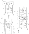
Figures 4 and 5 exemplify possible implementations of coupling said impedance (in the present examples, the resistance of resistor Rc) to theinput 20a of eachdriver 20. - For example,
Figures 4 and 5 exemplify the possibility of embedding a resistor Rc into an e.g. plastic casing, substantially shaped as a bridge and adapted to be vested ontocasing 12 of device 10 (after an optional temporary removal ofcover 18, or by taking advantage of openings or interruptions thereof, or of an optional corresponding sealing mass) in the location where a seat for the insertion of a resistor Rc is to be arranged. - In one or more embodiments, such an
insert 26 may be provided e.g. with electrical contacts (rheophores) 26a, adapted toelectrically contact lines 24a so as to couple resistor Rc to input 20a ofdriver 20. - Thanks to the possibility of selectively adjusting the lighting level produced by each unit A, one or more embodiments offer particularly flexible usage options.
- For example, said variation of the lighting brightness in different areas or sections of device 10 (see for example
Figure 1 ) may be performed by the final user, without requiring the intervention of a skilled worker or the use of specific tools. - One or more embodiments may therefore concern a lighting device (e.g. 10), including
- an elongate support element (e.g. 12),
- a plurality of lighting units (e.g. A) distributed along the length of said support element, each of said units including:
- a set of electrically-powered light radiation sources (e.g. 16),
- a driver (e.g. 20) supplying said set of light radiation sources with a supply current having an intensity (e.g. Iext) which is a function of an impedance (e.g. resistance) value sensed at a current control input (e.g. 20a) of the driver,
- One or more embodiments may include a plurality of said seats for receiving respective lighting adjustment impedances, each seat of said plurality of seats having an electrical connection to the current control input of the driver of a respective unit in said plurality of lighting units distributed along the length of said support element.
- In one or more embodiments, said elongate support element may include a channel-like housing with at least one partition separating two adjacent units of said plurality of lighting units, wherein said seat is located at said at least one partition.
- In one or more embodiments, said electrical connection to the current control input of said at least one driver may include a connection (e.g. 24) exposed to the electrical coupling with terminals (e.g. 26a) of a lighting adjustment impedance arranged at said seat.
- One or more embodiments may include a reference impedance (e.g. Rext) coupled to said current control input of said at least one driver, wherein said lighting adjustment impedance arranged in said seat is electrically coupled, optionally in parallel, to said reference impedance.
- One or more embodiments may include an assortment of said lighting adjustment impedances received in respective inserts (e.g. 26) coupleable to said elongated support element.
- In one or more embodiments, said electrically-powered light radiation sources may include LED sources.
- One or more embodiments may concern a method of providing adjustable lighting levels along a line, the method including:
- providing a lighting device according to one or more embodiments,
- arranging said lighting device with said elongated support element extending along said line, and
- coupling at least one lighting adjustment impedance to said at least one seat.
- Without prejudice to the basic principles, the details and the embodiments may vary, even appreciably, with respect to what has been described herein by way of non-limiting example only, without departing from the extent of protection.
- The extent of protection is defined by the annexed claims.
Claims (8)
- A lighting device (10), including:- an elongate support element (12),- a plurality of lighting units (A) distributed along the length of said support element (12), each of said units (A) including:- a set of electrically-powered light radiation sources (16),- a driver (20) supplying said set of light radiation sources (16) with a supply current having an intensity (Iext) which is a function of an impedance value sensed at a current control input (20a) of the driver (20),wherein at least one of said lighting units (A) includes a seat (24) for a lighting adjustment impedance (Rc), said seat (24) having an electrical connection (24a) to the current control input (20a) of at least one driver (20), wherein the intensity of the current supplied by said at least one driver (20) to a respective set of light radiation sources (16) is a function of the impedance value of a lighting adjustment impedance (Rc) arranged at said seat (24).
- The lighting device (10) of claim 1, including a plurality of said seats (24) for receiving respective lighting adjustment impedances (Rc), each seat of said plurality of seats having an electrical connection (20a) to the current control input (20a) of the driver (20) of a respective unit (A) in said plurality of lighting units distributed along the length of said support element (12).
- The lighting device (10) of claim 1 or claim 2, wherein said elongate support element (12) includes a channel-like housing with at least one partition (24) separating two adjacent units of said plurality of lighting units (A), wherein said seat is located at said at least one partition (24).
- The lighting device (10) of any of the preceding claims, wherein said electrical connection (24a) to the current control input (20a) of said at least one driver (20) includes a connection exposed to electrical coupling with terminals (26a) of a lighting adjustment impedance (Rc) arranged at said seat.
- The lighting device (10) of any of the preceding claims, including a reference impedance (Rext) coupled to said current control input (20a) of said at least one driver (20), wherein said lighting adjustment impedance (Rc) arranged in said seat (24) is electrically coupled, preferably in parallel, to said reference impedance (Rext).
- The lighting device (10) of any of the preceding claims, including an assortment of said lighting adjustment impedances (Rc) arranged in respective inserts (26) couplable to said elongated support element (12).
- The lighting device (10) of any of the preceding claims, wherein said electrically-powered light radiation sources include LED light sources (16).
- A method of providing adjustable lighting levels along a line, the method including:- providing a lighting device (10) according to any of claims 1 to 7,- arranging said lighting device (10) with said elongated support element (12) extending along said line, and- coupling at least one lighting adjustment impedance (Rc) to said at least one seat (24).
Applications Claiming Priority (1)
| Application Number | Priority Date | Filing Date | Title |
|---|---|---|---|
| IT201600087752 | 2016-08-29 |
Publications (2)
| Publication Number | Publication Date |
|---|---|
| EP3290787A1 true EP3290787A1 (en) | 2018-03-07 |
| EP3290787B1 EP3290787B1 (en) | 2019-05-15 |
Family
ID=58606318
Family Applications (1)
| Application Number | Title | Priority Date | Filing Date |
|---|---|---|---|
| EP17186384.8A Not-in-force EP3290787B1 (en) | 2016-08-29 | 2017-08-16 | A lighting device and corresponding method |
Country Status (2)
| Country | Link |
|---|---|
| US (1) | US10356876B2 (en) |
| EP (1) | EP3290787B1 (en) |
Cited By (1)
| Publication number | Priority date | Publication date | Assignee | Title |
|---|---|---|---|---|
| EP3715702A1 (en) * | 2019-03-28 | 2020-09-30 | Stepan Engineering GmbH | Constant voltage led strip (selv) |
Families Citing this family (1)
| Publication number | Priority date | Publication date | Assignee | Title |
|---|---|---|---|---|
| CN117072941B (en) * | 2023-08-14 | 2024-07-19 | 深圳市格罗克森科技有限公司 | Child sleep management lamp equipment |
Citations (4)
| Publication number | Priority date | Publication date | Assignee | Title |
|---|---|---|---|---|
| JP2005123178A (en) * | 2003-09-24 | 2005-05-12 | Toshiba Lighting & Technology Corp | Lighting device |
| WO2012104800A2 (en) * | 2011-02-04 | 2012-08-09 | Koninklijke Philips Electronics N.V. | Lighting unit with led strip |
| WO2014178595A1 (en) * | 2013-04-30 | 2014-11-06 | 주식회사 린노 | Line-type lighting device that can be individually controlled |
| EP3012511A1 (en) * | 2014-10-21 | 2016-04-27 | RIDI Leuchten GmbH | Light with lamp |
Family Cites Families (3)
| Publication number | Priority date | Publication date | Assignee | Title |
|---|---|---|---|---|
| JP5476325B2 (en) * | 2011-02-28 | 2014-04-23 | シャープ株式会社 | LED drive circuit, LED illumination lamp, LED illumination device, and LED illumination system |
| US20140145631A1 (en) * | 2012-11-28 | 2014-05-29 | Shenzhen China Star Optoelectronics Technology Co. Ltd. | Backlight driver circuit and liquid crystal display device |
| US9360174B2 (en) * | 2013-12-05 | 2016-06-07 | Ketra, Inc. | Linear LED illumination device with improved color mixing |
-
2017
- 2017-08-16 EP EP17186384.8A patent/EP3290787B1/en not_active Not-in-force
- 2017-08-29 US US15/688,931 patent/US10356876B2/en active Active
Patent Citations (4)
| Publication number | Priority date | Publication date | Assignee | Title |
|---|---|---|---|---|
| JP2005123178A (en) * | 2003-09-24 | 2005-05-12 | Toshiba Lighting & Technology Corp | Lighting device |
| WO2012104800A2 (en) * | 2011-02-04 | 2012-08-09 | Koninklijke Philips Electronics N.V. | Lighting unit with led strip |
| WO2014178595A1 (en) * | 2013-04-30 | 2014-11-06 | 주식회사 린노 | Line-type lighting device that can be individually controlled |
| EP3012511A1 (en) * | 2014-10-21 | 2016-04-27 | RIDI Leuchten GmbH | Light with lamp |
Cited By (5)
| Publication number | Priority date | Publication date | Assignee | Title |
|---|---|---|---|---|
| EP3715702A1 (en) * | 2019-03-28 | 2020-09-30 | Stepan Engineering GmbH | Constant voltage led strip (selv) |
| WO2020194236A1 (en) | 2019-03-28 | 2020-10-01 | Stepan Engineering Gmbh | Constant voltage led strip (selv) |
| EP3948062A1 (en) * | 2019-03-28 | 2022-02-09 | Stepan Engineering GmbH | Constant voltage led strip (selv) |
| EP4628783A2 (en) | 2019-03-28 | 2025-10-08 | Stepan Engineering GmbH | Constant voltage led strip (selv) |
| EP4628783A3 (en) * | 2019-03-28 | 2025-11-12 | Stepan Engineering GmbH | Constant voltage led strip (selv) |
Also Published As
| Publication number | Publication date |
|---|---|
| EP3290787B1 (en) | 2019-05-15 |
| US10356876B2 (en) | 2019-07-16 |
| US20180063919A1 (en) | 2018-03-01 |
Similar Documents
| Publication | Publication Date | Title |
|---|---|---|
| DE102014111746B4 (en) | Light source and lighting device | |
| US8398261B2 (en) | Lighting strips with improved manufacturability | |
| US9265100B2 (en) | Driving circuit of semiconductor-type light source for vehicle lighting device and a vehicle lighting device | |
| US9271363B2 (en) | Lighting device having LED elements | |
| RU2594293C2 (en) | Light source containing led tape | |
| JP5120537B2 (en) | Lighting device | |
| US20120081899A1 (en) | Luminaire system and method | |
| EP3290787B1 (en) | A lighting device and corresponding method | |
| US8749143B1 (en) | Automotive lighting device and controller | |
| JP6839658B2 (en) | LED light strip and its manufacturing method | |
| RU2013137838A (en) | LUMINOUS STRIP FOR SPORTS AND OTHER EQUIPMENT AND SPORTS EQUIPMENT FOR BALL GAMES OR SIMILAR GAMES CONTAINING SUCH STRIP | |
| US10465889B2 (en) | Light board | |
| EP3948062B1 (en) | Constant voltage led strip (selv) | |
| KR20160106431A (en) | Constant current chip embedding led package module | |
| US20210100079A1 (en) | Led luminaire multiplexing with constant current driver | |
| KR102817789B1 (en) | Lighting fixture | |
| CN205566743U (en) | Light-emitting diode circuit board structure that maintains uniform brightness | |
| CN104819388A (en) | Light emitting module and lighting device | |
| GB2623763A (en) | Controlled environment agriculture lighting assembly, PCB and method | |
| EP2775795A1 (en) | Dimmable LED reading light unit, arrangement of power supply and dimmable LED reading light unit and method of replacing a dimmable light unit by a dimmable LED reading light unit | |
| CN107926092B (en) | Energy supply circuit for lighting modules | |
| CN109716863B (en) | Multi-pad multi-contact LED package with tapped linear driver | |
| EP3453230B1 (en) | Multi-pad, multi-junction led package with tapped linear driver | |
| KR20160021165A (en) | PCB Pattern For LED Lamp, The LED PCB And The LED Lighting Apparatus Thereby | |
| US11359775B2 (en) | Series connected parallel array of LEDs |
Legal Events
| Date | Code | Title | Description |
|---|---|---|---|
| PUAI | Public reference made under article 153(3) epc to a published international application that has entered the european phase |
Free format text: ORIGINAL CODE: 0009012 |
|
| STAA | Information on the status of an ep patent application or granted ep patent |
Free format text: STATUS: THE APPLICATION HAS BEEN PUBLISHED |
|
| AK | Designated contracting states |
Kind code of ref document: A1 Designated state(s): AL AT BE BG CH CY CZ DE DK EE ES FI FR GB GR HR HU IE IS IT LI LT LU LV MC MK MT NL NO PL PT RO RS SE SI SK SM TR |
|
| AX | Request for extension of the european patent |
Extension state: BA ME |
|
| RAP1 | Party data changed (applicant data changed or rights of an application transferred) |
Owner name: OSRAM GMBH Owner name: OSRAM S.P.A. - SOCIETA' RIUNITE OSRAM EDISON CLERI |
|
| STAA | Information on the status of an ep patent application or granted ep patent |
Free format text: STATUS: REQUEST FOR EXAMINATION WAS MADE |
|
| 17P | Request for examination filed |
Effective date: 20180629 |
|
| RBV | Designated contracting states (corrected) |
Designated state(s): AL AT BE BG CH CY CZ DE DK EE ES FI FR GB GR HR HU IE IS IT LI LT LU LV MC MK MT NL NO PL PT RO RS SE SI SK SM TR |
|
| GRAP | Despatch of communication of intention to grant a patent |
Free format text: ORIGINAL CODE: EPIDOSNIGR1 |
|
| STAA | Information on the status of an ep patent application or granted ep patent |
Free format text: STATUS: GRANT OF PATENT IS INTENDED |
|
| INTG | Intention to grant announced |
Effective date: 20181212 |
|
| GRAS | Grant fee paid |
Free format text: ORIGINAL CODE: EPIDOSNIGR3 |
|
| GRAA | (expected) grant |
Free format text: ORIGINAL CODE: 0009210 |
|
| STAA | Information on the status of an ep patent application or granted ep patent |
Free format text: STATUS: THE PATENT HAS BEEN GRANTED |
|
| AK | Designated contracting states |
Kind code of ref document: B1 Designated state(s): AL AT BE BG CH CY CZ DE DK EE ES FI FR GB GR HR HU IE IS IT LI LT LU LV MC MK MT NL NO PL PT RO RS SE SI SK SM TR |
|
| REG | Reference to a national code |
Ref country code: CH Ref legal event code: EP |
|
| REG | Reference to a national code |
Ref country code: DE Ref legal event code: R096 Ref document number: 602017003888 Country of ref document: DE |
|
| REG | Reference to a national code |
Ref country code: IE Ref legal event code: FG4D |
|
| REG | Reference to a national code |
Ref country code: NL Ref legal event code: MP Effective date: 20190515 |
|
| REG | Reference to a national code |
Ref country code: LT Ref legal event code: MG4D |
|
| PG25 | Lapsed in a contracting state [announced via postgrant information from national office to epo] |
Ref country code: FI Free format text: LAPSE BECAUSE OF FAILURE TO SUBMIT A TRANSLATION OF THE DESCRIPTION OR TO PAY THE FEE WITHIN THE PRESCRIBED TIME-LIMIT Effective date: 20190515 Ref country code: HR Free format text: LAPSE BECAUSE OF FAILURE TO SUBMIT A TRANSLATION OF THE DESCRIPTION OR TO PAY THE FEE WITHIN THE PRESCRIBED TIME-LIMIT Effective date: 20190515 Ref country code: AL Free format text: LAPSE BECAUSE OF FAILURE TO SUBMIT A TRANSLATION OF THE DESCRIPTION OR TO PAY THE FEE WITHIN THE PRESCRIBED TIME-LIMIT Effective date: 20190515 Ref country code: SE Free format text: LAPSE BECAUSE OF FAILURE TO SUBMIT A TRANSLATION OF THE DESCRIPTION OR TO PAY THE FEE WITHIN THE PRESCRIBED TIME-LIMIT Effective date: 20190515 Ref country code: NO Free format text: LAPSE BECAUSE OF FAILURE TO SUBMIT A TRANSLATION OF THE DESCRIPTION OR TO PAY THE FEE WITHIN THE PRESCRIBED TIME-LIMIT Effective date: 20190815 Ref country code: PT Free format text: LAPSE BECAUSE OF FAILURE TO SUBMIT A TRANSLATION OF THE DESCRIPTION OR TO PAY THE FEE WITHIN THE PRESCRIBED TIME-LIMIT Effective date: 20190915 Ref country code: ES Free format text: LAPSE BECAUSE OF FAILURE TO SUBMIT A TRANSLATION OF THE DESCRIPTION OR TO PAY THE FEE WITHIN THE PRESCRIBED TIME-LIMIT Effective date: 20190515 Ref country code: LT Free format text: LAPSE BECAUSE OF FAILURE TO SUBMIT A TRANSLATION OF THE DESCRIPTION OR TO PAY THE FEE WITHIN THE PRESCRIBED TIME-LIMIT Effective date: 20190515 Ref country code: NL Free format text: LAPSE BECAUSE OF FAILURE TO SUBMIT A TRANSLATION OF THE DESCRIPTION OR TO PAY THE FEE WITHIN THE PRESCRIBED TIME-LIMIT Effective date: 20190515 |
|
| PG25 | Lapsed in a contracting state [announced via postgrant information from national office to epo] |
Ref country code: RS Free format text: LAPSE BECAUSE OF FAILURE TO SUBMIT A TRANSLATION OF THE DESCRIPTION OR TO PAY THE FEE WITHIN THE PRESCRIBED TIME-LIMIT Effective date: 20190515 Ref country code: BG Free format text: LAPSE BECAUSE OF FAILURE TO SUBMIT A TRANSLATION OF THE DESCRIPTION OR TO PAY THE FEE WITHIN THE PRESCRIBED TIME-LIMIT Effective date: 20190815 Ref country code: GR Free format text: LAPSE BECAUSE OF FAILURE TO SUBMIT A TRANSLATION OF THE DESCRIPTION OR TO PAY THE FEE WITHIN THE PRESCRIBED TIME-LIMIT Effective date: 20190816 Ref country code: LV Free format text: LAPSE BECAUSE OF FAILURE TO SUBMIT A TRANSLATION OF THE DESCRIPTION OR TO PAY THE FEE WITHIN THE PRESCRIBED TIME-LIMIT Effective date: 20190515 |
|
| REG | Reference to a national code |
Ref country code: AT Ref legal event code: MK05 Ref document number: 1133864 Country of ref document: AT Kind code of ref document: T Effective date: 20190515 |
|
| PG25 | Lapsed in a contracting state [announced via postgrant information from national office to epo] |
Ref country code: SK Free format text: LAPSE BECAUSE OF FAILURE TO SUBMIT A TRANSLATION OF THE DESCRIPTION OR TO PAY THE FEE WITHIN THE PRESCRIBED TIME-LIMIT Effective date: 20190515 Ref country code: DK Free format text: LAPSE BECAUSE OF FAILURE TO SUBMIT A TRANSLATION OF THE DESCRIPTION OR TO PAY THE FEE WITHIN THE PRESCRIBED TIME-LIMIT Effective date: 20190515 Ref country code: EE Free format text: LAPSE BECAUSE OF FAILURE TO SUBMIT A TRANSLATION OF THE DESCRIPTION OR TO PAY THE FEE WITHIN THE PRESCRIBED TIME-LIMIT Effective date: 20190515 Ref country code: AT Free format text: LAPSE BECAUSE OF FAILURE TO SUBMIT A TRANSLATION OF THE DESCRIPTION OR TO PAY THE FEE WITHIN THE PRESCRIBED TIME-LIMIT Effective date: 20190515 Ref country code: CZ Free format text: LAPSE BECAUSE OF FAILURE TO SUBMIT A TRANSLATION OF THE DESCRIPTION OR TO PAY THE FEE WITHIN THE PRESCRIBED TIME-LIMIT Effective date: 20190515 |
|
| REG | Reference to a national code |
Ref country code: DE Ref legal event code: R097 Ref document number: 602017003888 Country of ref document: DE |
|
| PG25 | Lapsed in a contracting state [announced via postgrant information from national office to epo] |
Ref country code: IT Free format text: LAPSE BECAUSE OF FAILURE TO SUBMIT A TRANSLATION OF THE DESCRIPTION OR TO PAY THE FEE WITHIN THE PRESCRIBED TIME-LIMIT Effective date: 20190515 Ref country code: SM Free format text: LAPSE BECAUSE OF FAILURE TO SUBMIT A TRANSLATION OF THE DESCRIPTION OR TO PAY THE FEE WITHIN THE PRESCRIBED TIME-LIMIT Effective date: 20190515 |
|
| PLBE | No opposition filed within time limit |
Free format text: ORIGINAL CODE: 0009261 |
|
| STAA | Information on the status of an ep patent application or granted ep patent |
Free format text: STATUS: NO OPPOSITION FILED WITHIN TIME LIMIT |
|
| PG25 | Lapsed in a contracting state [announced via postgrant information from national office to epo] |
Ref country code: TR Free format text: LAPSE BECAUSE OF FAILURE TO SUBMIT A TRANSLATION OF THE DESCRIPTION OR TO PAY THE FEE WITHIN THE PRESCRIBED TIME-LIMIT Effective date: 20190515 |
|
| 26N | No opposition filed |
Effective date: 20200218 |
|
| PG25 | Lapsed in a contracting state [announced via postgrant information from national office to epo] |
Ref country code: PL Free format text: LAPSE BECAUSE OF FAILURE TO SUBMIT A TRANSLATION OF THE DESCRIPTION OR TO PAY THE FEE WITHIN THE PRESCRIBED TIME-LIMIT Effective date: 20190515 |
|
| PG25 | Lapsed in a contracting state [announced via postgrant information from national office to epo] |
Ref country code: SI Free format text: LAPSE BECAUSE OF FAILURE TO SUBMIT A TRANSLATION OF THE DESCRIPTION OR TO PAY THE FEE WITHIN THE PRESCRIBED TIME-LIMIT Effective date: 20190515 Ref country code: LU Free format text: LAPSE BECAUSE OF NON-PAYMENT OF DUE FEES Effective date: 20190816 Ref country code: MC Free format text: LAPSE BECAUSE OF FAILURE TO SUBMIT A TRANSLATION OF THE DESCRIPTION OR TO PAY THE FEE WITHIN THE PRESCRIBED TIME-LIMIT Effective date: 20190515 |
|
| REG | Reference to a national code |
Ref country code: BE Ref legal event code: MM Effective date: 20190831 |
|
| PG25 | Lapsed in a contracting state [announced via postgrant information from national office to epo] |
Ref country code: FR Free format text: LAPSE BECAUSE OF NON-PAYMENT OF DUE FEES Effective date: 20190831 Ref country code: IE Free format text: LAPSE BECAUSE OF NON-PAYMENT OF DUE FEES Effective date: 20190816 |
|
| PG25 | Lapsed in a contracting state [announced via postgrant information from national office to epo] |
Ref country code: BE Free format text: LAPSE BECAUSE OF NON-PAYMENT OF DUE FEES Effective date: 20190831 |
|
| REG | Reference to a national code |
Ref country code: CH Ref legal event code: PL |
|
| PG25 | Lapsed in a contracting state [announced via postgrant information from national office to epo] |
Ref country code: LI Free format text: LAPSE BECAUSE OF NON-PAYMENT OF DUE FEES Effective date: 20200831 Ref country code: CH Free format text: LAPSE BECAUSE OF NON-PAYMENT OF DUE FEES Effective date: 20200831 Ref country code: RO Free format text: LAPSE BECAUSE OF FAILURE TO SUBMIT A TRANSLATION OF THE DESCRIPTION OR TO PAY THE FEE WITHIN THE PRESCRIBED TIME-LIMIT Effective date: 20190515 |
|
| PG25 | Lapsed in a contracting state [announced via postgrant information from national office to epo] |
Ref country code: CY Free format text: LAPSE BECAUSE OF FAILURE TO SUBMIT A TRANSLATION OF THE DESCRIPTION OR TO PAY THE FEE WITHIN THE PRESCRIBED TIME-LIMIT Effective date: 20190515 |
|
| PG25 | Lapsed in a contracting state [announced via postgrant information from national office to epo] |
Ref country code: IS Free format text: LAPSE BECAUSE OF FAILURE TO SUBMIT A TRANSLATION OF THE DESCRIPTION OR TO PAY THE FEE WITHIN THE PRESCRIBED TIME-LIMIT Effective date: 20190915 |
|
| PG25 | Lapsed in a contracting state [announced via postgrant information from national office to epo] |
Ref country code: MT Free format text: LAPSE BECAUSE OF FAILURE TO SUBMIT A TRANSLATION OF THE DESCRIPTION OR TO PAY THE FEE WITHIN THE PRESCRIBED TIME-LIMIT Effective date: 20190515 Ref country code: HU Free format text: LAPSE BECAUSE OF FAILURE TO SUBMIT A TRANSLATION OF THE DESCRIPTION OR TO PAY THE FEE WITHIN THE PRESCRIBED TIME-LIMIT; INVALID AB INITIO Effective date: 20170816 |
|
| GBPC | Gb: european patent ceased through non-payment of renewal fee |
Effective date: 20210816 |
|
| PG25 | Lapsed in a contracting state [announced via postgrant information from national office to epo] |
Ref country code: MK Free format text: LAPSE BECAUSE OF FAILURE TO SUBMIT A TRANSLATION OF THE DESCRIPTION OR TO PAY THE FEE WITHIN THE PRESCRIBED TIME-LIMIT Effective date: 20190515 |
|
| PG25 | Lapsed in a contracting state [announced via postgrant information from national office to epo] |
Ref country code: GB Free format text: LAPSE BECAUSE OF NON-PAYMENT OF DUE FEES Effective date: 20210816 |
|
| REG | Reference to a national code |
Ref country code: DE Ref legal event code: R081 Ref document number: 602017003888 Country of ref document: DE Owner name: OPTOTRONIC GMBH, DE Free format text: FORMER OWNER: OSRAM GMBH, 80807 MUENCHEN, DE Ref country code: DE Ref legal event code: R081 Ref document number: 602017003888 Country of ref document: DE Owner name: INVENTRONICS GMBH, DE Free format text: FORMER OWNER: OSRAM GMBH, 80807 MUENCHEN, DE |
|
| PGFP | Annual fee paid to national office [announced via postgrant information from national office to epo] |
Ref country code: DE Payment date: 20230831 Year of fee payment: 7 |
|
| REG | Reference to a national code |
Ref country code: DE Ref legal event code: R081 Ref document number: 602017003888 Country of ref document: DE Owner name: INVENTRONICS GMBH, DE Free format text: FORMER OWNER: OPTOTRONIC GMBH, 85748 GARCHING, DE |
|
| REG | Reference to a national code |
Ref country code: DE Ref legal event code: R119 Ref document number: 602017003888 Country of ref document: DE |
|
| PG25 | Lapsed in a contracting state [announced via postgrant information from national office to epo] |
Ref country code: DE Free format text: LAPSE BECAUSE OF NON-PAYMENT OF DUE FEES Effective date: 20250301 |