EP3290734A1 - Disc brake apparatus - Google Patents
Disc brake apparatus Download PDFInfo
- Publication number
- EP3290734A1 EP3290734A1 EP16786384.4A EP16786384A EP3290734A1 EP 3290734 A1 EP3290734 A1 EP 3290734A1 EP 16786384 A EP16786384 A EP 16786384A EP 3290734 A1 EP3290734 A1 EP 3290734A1
- Authority
- EP
- European Patent Office
- Prior art keywords
- pressing force
- cam lever
- disc brake
- brake apparatus
- cam
- Prior art date
- Legal status (The legal status is an assumption and is not a legal conclusion. Google has not performed a legal analysis and makes no representation as to the accuracy of the status listed.)
- Withdrawn
Links
- 230000007246 mechanism Effects 0.000 claims abstract description 71
- 230000005540 biological transmission Effects 0.000 claims abstract description 26
- 238000010276 construction Methods 0.000 claims description 7
- 230000009467 reduction Effects 0.000 description 6
- 230000009471 action Effects 0.000 description 4
- 238000005192 partition Methods 0.000 description 4
- 125000006850 spacer group Chemical group 0.000 description 4
- 239000000463 material Substances 0.000 description 3
- 241001397809 Hakea leucoptera Species 0.000 description 2
- 230000008859 change Effects 0.000 description 2
- 239000000470 constituent Substances 0.000 description 2
- 239000000428 dust Substances 0.000 description 2
- 230000004044 response Effects 0.000 description 2
- 230000004308 accommodation Effects 0.000 description 1
- 238000005452 bending Methods 0.000 description 1
- 230000008901 benefit Effects 0.000 description 1
- 230000000295 complement effect Effects 0.000 description 1
- 238000005516 engineering process Methods 0.000 description 1
- 239000012530 fluid Substances 0.000 description 1
- 230000000149 penetrating effect Effects 0.000 description 1
- 230000003245 working effect Effects 0.000 description 1
Images




Classifications
-
- F—MECHANICAL ENGINEERING; LIGHTING; HEATING; WEAPONS; BLASTING
- F16—ENGINEERING ELEMENTS AND UNITS; GENERAL MEASURES FOR PRODUCING AND MAINTAINING EFFECTIVE FUNCTIONING OF MACHINES OR INSTALLATIONS; THERMAL INSULATION IN GENERAL
- F16D—COUPLINGS FOR TRANSMITTING ROTATION; CLUTCHES; BRAKES
- F16D55/00—Brakes with substantially-radial braking surfaces pressed together in axial direction, e.g. disc brakes
- F16D55/02—Brakes with substantially-radial braking surfaces pressed together in axial direction, e.g. disc brakes with axially-movable discs or pads pressed against axially-located rotating members
- F16D55/22—Brakes with substantially-radial braking surfaces pressed together in axial direction, e.g. disc brakes with axially-movable discs or pads pressed against axially-located rotating members by clamping an axially-located rotating disc between movable braking members, e.g. movable brake discs or brake pads
- F16D55/224—Brakes with substantially-radial braking surfaces pressed together in axial direction, e.g. disc brakes with axially-movable discs or pads pressed against axially-located rotating members by clamping an axially-located rotating disc between movable braking members, e.g. movable brake discs or brake pads with a common actuating member for the braking members
- F16D55/225—Brakes with substantially-radial braking surfaces pressed together in axial direction, e.g. disc brakes with axially-movable discs or pads pressed against axially-located rotating members by clamping an axially-located rotating disc between movable braking members, e.g. movable brake discs or brake pads with a common actuating member for the braking members the braking members being brake pads
- F16D55/226—Brakes with substantially-radial braking surfaces pressed together in axial direction, e.g. disc brakes with axially-movable discs or pads pressed against axially-located rotating members by clamping an axially-located rotating disc between movable braking members, e.g. movable brake discs or brake pads with a common actuating member for the braking members the braking members being brake pads in which the common actuating member is moved axially, e.g. floating caliper disc brakes
-
- F—MECHANICAL ENGINEERING; LIGHTING; HEATING; WEAPONS; BLASTING
- F16—ENGINEERING ELEMENTS AND UNITS; GENERAL MEASURES FOR PRODUCING AND MAINTAINING EFFECTIVE FUNCTIONING OF MACHINES OR INSTALLATIONS; THERMAL INSULATION IN GENERAL
- F16D—COUPLINGS FOR TRANSMITTING ROTATION; CLUTCHES; BRAKES
- F16D65/00—Parts or details
- F16D65/005—Components of axially engaging brakes not otherwise provided for
- F16D65/0068—Brake calipers
-
- F—MECHANICAL ENGINEERING; LIGHTING; HEATING; WEAPONS; BLASTING
- F16—ENGINEERING ELEMENTS AND UNITS; GENERAL MEASURES FOR PRODUCING AND MAINTAINING EFFECTIVE FUNCTIONING OF MACHINES OR INSTALLATIONS; THERMAL INSULATION IN GENERAL
- F16D—COUPLINGS FOR TRANSMITTING ROTATION; CLUTCHES; BRAKES
- F16D65/00—Parts or details
- F16D65/02—Braking members; Mounting thereof
-
- F—MECHANICAL ENGINEERING; LIGHTING; HEATING; WEAPONS; BLASTING
- F16—ENGINEERING ELEMENTS AND UNITS; GENERAL MEASURES FOR PRODUCING AND MAINTAINING EFFECTIVE FUNCTIONING OF MACHINES OR INSTALLATIONS; THERMAL INSULATION IN GENERAL
- F16D—COUPLINGS FOR TRANSMITTING ROTATION; CLUTCHES; BRAKES
- F16D65/00—Parts or details
- F16D65/14—Actuating mechanisms for brakes; Means for initiating operation at a predetermined position
- F16D65/16—Actuating mechanisms for brakes; Means for initiating operation at a predetermined position arranged in or on the brake
- F16D65/18—Actuating mechanisms for brakes; Means for initiating operation at a predetermined position arranged in or on the brake adapted for drawing members together, e.g. for disc brakes
-
- F—MECHANICAL ENGINEERING; LIGHTING; HEATING; WEAPONS; BLASTING
- F16—ENGINEERING ELEMENTS AND UNITS; GENERAL MEASURES FOR PRODUCING AND MAINTAINING EFFECTIVE FUNCTIONING OF MACHINES OR INSTALLATIONS; THERMAL INSULATION IN GENERAL
- F16D—COUPLINGS FOR TRANSMITTING ROTATION; CLUTCHES; BRAKES
- F16D65/00—Parts or details
- F16D65/14—Actuating mechanisms for brakes; Means for initiating operation at a predetermined position
- F16D65/16—Actuating mechanisms for brakes; Means for initiating operation at a predetermined position arranged in or on the brake
- F16D65/18—Actuating mechanisms for brakes; Means for initiating operation at a predetermined position arranged in or on the brake adapted for drawing members together, e.g. for disc brakes
- F16D65/183—Actuating mechanisms for brakes; Means for initiating operation at a predetermined position arranged in or on the brake adapted for drawing members together, e.g. for disc brakes with force-transmitting members arranged side by side acting on a spot type force-applying member
-
- F—MECHANICAL ENGINEERING; LIGHTING; HEATING; WEAPONS; BLASTING
- F16—ENGINEERING ELEMENTS AND UNITS; GENERAL MEASURES FOR PRODUCING AND MAINTAINING EFFECTIVE FUNCTIONING OF MACHINES OR INSTALLATIONS; THERMAL INSULATION IN GENERAL
- F16D—COUPLINGS FOR TRANSMITTING ROTATION; CLUTCHES; BRAKES
- F16D65/00—Parts or details
- F16D65/38—Slack adjusters
- F16D65/40—Slack adjusters mechanical
- F16D65/52—Slack adjusters mechanical self-acting in one direction for adjusting excessive play
- F16D65/56—Slack adjusters mechanical self-acting in one direction for adjusting excessive play with screw-thread and nut
-
- F—MECHANICAL ENGINEERING; LIGHTING; HEATING; WEAPONS; BLASTING
- F16—ENGINEERING ELEMENTS AND UNITS; GENERAL MEASURES FOR PRODUCING AND MAINTAINING EFFECTIVE FUNCTIONING OF MACHINES OR INSTALLATIONS; THERMAL INSULATION IN GENERAL
- F16D—COUPLINGS FOR TRANSMITTING ROTATION; CLUTCHES; BRAKES
- F16D65/00—Parts or details
- F16D65/38—Slack adjusters
- F16D65/40—Slack adjusters mechanical
- F16D65/52—Slack adjusters mechanical self-acting in one direction for adjusting excessive play
- F16D65/56—Slack adjusters mechanical self-acting in one direction for adjusting excessive play with screw-thread and nut
- F16D65/567—Slack adjusters mechanical self-acting in one direction for adjusting excessive play with screw-thread and nut for mounting on a disc brake
-
- F—MECHANICAL ENGINEERING; LIGHTING; HEATING; WEAPONS; BLASTING
- F16—ENGINEERING ELEMENTS AND UNITS; GENERAL MEASURES FOR PRODUCING AND MAINTAINING EFFECTIVE FUNCTIONING OF MACHINES OR INSTALLATIONS; THERMAL INSULATION IN GENERAL
- F16H—GEARING
- F16H25/00—Gearings comprising primarily only cams, cam-followers and screw-and-nut mechanisms
- F16H25/18—Gearings comprising primarily only cams, cam-followers and screw-and-nut mechanisms for conveying or interconverting oscillating or reciprocating motions
- F16H25/20—Screw mechanisms
-
- F—MECHANICAL ENGINEERING; LIGHTING; HEATING; WEAPONS; BLASTING
- F16—ENGINEERING ELEMENTS AND UNITS; GENERAL MEASURES FOR PRODUCING AND MAINTAINING EFFECTIVE FUNCTIONING OF MACHINES OR INSTALLATIONS; THERMAL INSULATION IN GENERAL
- F16D—COUPLINGS FOR TRANSMITTING ROTATION; CLUTCHES; BRAKES
- F16D55/00—Brakes with substantially-radial braking surfaces pressed together in axial direction, e.g. disc brakes
- F16D2055/0004—Parts or details of disc brakes
- F16D2055/0016—Brake calipers
-
- F—MECHANICAL ENGINEERING; LIGHTING; HEATING; WEAPONS; BLASTING
- F16—ENGINEERING ELEMENTS AND UNITS; GENERAL MEASURES FOR PRODUCING AND MAINTAINING EFFECTIVE FUNCTIONING OF MACHINES OR INSTALLATIONS; THERMAL INSULATION IN GENERAL
- F16D—COUPLINGS FOR TRANSMITTING ROTATION; CLUTCHES; BRAKES
- F16D2121/00—Type of actuator operation force
- F16D2121/02—Fluid pressure
- F16D2121/08—Fluid pressure acting on a membrane-type actuator, e.g. for gas pressure
-
- F—MECHANICAL ENGINEERING; LIGHTING; HEATING; WEAPONS; BLASTING
- F16—ENGINEERING ELEMENTS AND UNITS; GENERAL MEASURES FOR PRODUCING AND MAINTAINING EFFECTIVE FUNCTIONING OF MACHINES OR INSTALLATIONS; THERMAL INSULATION IN GENERAL
- F16D—COUPLINGS FOR TRANSMITTING ROTATION; CLUTCHES; BRAKES
- F16D2121/00—Type of actuator operation force
- F16D2121/14—Mechanical
-
- F—MECHANICAL ENGINEERING; LIGHTING; HEATING; WEAPONS; BLASTING
- F16—ENGINEERING ELEMENTS AND UNITS; GENERAL MEASURES FOR PRODUCING AND MAINTAINING EFFECTIVE FUNCTIONING OF MACHINES OR INSTALLATIONS; THERMAL INSULATION IN GENERAL
- F16D—COUPLINGS FOR TRANSMITTING ROTATION; CLUTCHES; BRAKES
- F16D2125/00—Components of actuators
- F16D2125/18—Mechanical mechanisms
- F16D2125/20—Mechanical mechanisms converting rotation to linear movement or vice versa
- F16D2125/22—Mechanical mechanisms converting rotation to linear movement or vice versa acting transversely to the axis of rotation
- F16D2125/28—Cams; Levers with cams
-
- F—MECHANICAL ENGINEERING; LIGHTING; HEATING; WEAPONS; BLASTING
- F16—ENGINEERING ELEMENTS AND UNITS; GENERAL MEASURES FOR PRODUCING AND MAINTAINING EFFECTIVE FUNCTIONING OF MACHINES OR INSTALLATIONS; THERMAL INSULATION IN GENERAL
- F16D—COUPLINGS FOR TRANSMITTING ROTATION; CLUTCHES; BRAKES
- F16D2125/00—Components of actuators
- F16D2125/18—Mechanical mechanisms
- F16D2125/20—Mechanical mechanisms converting rotation to linear movement or vice versa
- F16D2125/34—Mechanical mechanisms converting rotation to linear movement or vice versa acting in the direction of the axis of rotation
- F16D2125/40—Screw-and-nut
-
- F—MECHANICAL ENGINEERING; LIGHTING; HEATING; WEAPONS; BLASTING
- F16—ENGINEERING ELEMENTS AND UNITS; GENERAL MEASURES FOR PRODUCING AND MAINTAINING EFFECTIVE FUNCTIONING OF MACHINES OR INSTALLATIONS; THERMAL INSULATION IN GENERAL
- F16D—COUPLINGS FOR TRANSMITTING ROTATION; CLUTCHES; BRAKES
- F16D2125/00—Components of actuators
- F16D2125/18—Mechanical mechanisms
- F16D2125/58—Mechanical mechanisms transmitting linear movement
- F16D2125/64—Levers
-
- F—MECHANICAL ENGINEERING; LIGHTING; HEATING; WEAPONS; BLASTING
- F16—ENGINEERING ELEMENTS AND UNITS; GENERAL MEASURES FOR PRODUCING AND MAINTAINING EFFECTIVE FUNCTIONING OF MACHINES OR INSTALLATIONS; THERMAL INSULATION IN GENERAL
- F16D—COUPLINGS FOR TRANSMITTING ROTATION; CLUTCHES; BRAKES
- F16D55/00—Brakes with substantially-radial braking surfaces pressed together in axial direction, e.g. disc brakes
- F16D55/02—Brakes with substantially-radial braking surfaces pressed together in axial direction, e.g. disc brakes with axially-movable discs or pads pressed against axially-located rotating members
- F16D55/22—Brakes with substantially-radial braking surfaces pressed together in axial direction, e.g. disc brakes with axially-movable discs or pads pressed against axially-located rotating members by clamping an axially-located rotating disc between movable braking members, e.g. movable brake discs or brake pads
- F16D55/224—Brakes with substantially-radial braking surfaces pressed together in axial direction, e.g. disc brakes with axially-movable discs or pads pressed against axially-located rotating members by clamping an axially-located rotating disc between movable braking members, e.g. movable brake discs or brake pads with a common actuating member for the braking members
- F16D55/225—Brakes with substantially-radial braking surfaces pressed together in axial direction, e.g. disc brakes with axially-movable discs or pads pressed against axially-located rotating members by clamping an axially-located rotating disc between movable braking members, e.g. movable brake discs or brake pads with a common actuating member for the braking members the braking members being brake pads
- F16D55/226—Brakes with substantially-radial braking surfaces pressed together in axial direction, e.g. disc brakes with axially-movable discs or pads pressed against axially-located rotating members by clamping an axially-located rotating disc between movable braking members, e.g. movable brake discs or brake pads with a common actuating member for the braking members the braking members being brake pads in which the common actuating member is moved axially, e.g. floating caliper disc brakes
- F16D55/2265—Brakes with substantially-radial braking surfaces pressed together in axial direction, e.g. disc brakes with axially-movable discs or pads pressed against axially-located rotating members by clamping an axially-located rotating disc between movable braking members, e.g. movable brake discs or brake pads with a common actuating member for the braking members the braking members being brake pads in which the common actuating member is moved axially, e.g. floating caliper disc brakes the axial movement being guided by one or more pins engaging bores in the brake support or the brake housing
- F16D55/227—Brakes with substantially-radial braking surfaces pressed together in axial direction, e.g. disc brakes with axially-movable discs or pads pressed against axially-located rotating members by clamping an axially-located rotating disc between movable braking members, e.g. movable brake discs or brake pads with a common actuating member for the braking members the braking members being brake pads in which the common actuating member is moved axially, e.g. floating caliper disc brakes the axial movement being guided by one or more pins engaging bores in the brake support or the brake housing by two or more pins
Definitions
- the present invention relates to a disc brake apparatus.
- Patent Literatures 1, 2 both relate to a disc brake apparatus of a type in which a pressing force with which brake pads hold a rotor is generated by rotating a cam using an air chamber as a source of power (an actuator).
- a disc brake apparatus having the mechanism described above there are known a disc brake apparatus of a type in which a cam is disposed on a shaft and the shaft penetrates a body and a disc brake apparatus of a type in which no shaft is provided and a cam is disposed at a distal end of a lever which is rotated.
- An object of the invention is to provide a disc brake apparatus having a construction which can prevent a reduction in body rigidity even in a case where a cam lever is adopted for use in a servo mechanism.
- the disc brake apparatus characterized as described above, even when the cam lever is adopted for use in the servo mechanism, it is possible to prevent a reduction in body rigidity. In addition, it is possible to enhance the assembling properties of the cam lever and the pressing force transmission mechanism.
- a disc brake apparatus 10 of this embodiment basically includes a caliper body 12, a support 60 and an actuator 50, and brake pads 66, 68 are pressed against sliding surface of a rotor 70 to thereby exhibit a braking force.
- the caliper body 12 basically includes a pressing force generating portion 14, a reaction force bearing portion 18 and bridge portions 16.
- the pressing force generating portion 14 is an element which accommodates a pressing force generating mechanism 22 including a piston 20 for generating a pressing force.
- the reaction force bearing portion 18 constitutes an element which is disposed so as to be opposite to the pressing force generating portion 14 across the motor 70 and which bears a pressing force from the piston 20 when generating a pressing force.
- a pad holding portion for holding the brake pad 68 is provided on a surface side of the reaction force bearing portion 18 which faces the rotor 70.
- the bridge portions 16 are elements which straddle an outer circumferential side of the rotor 70 to connect the pressing force generating portion 14 and the reaction force bearing portion 18 together.
- the pressing force generating portion 14 makes up a frame structure which is formed into a frame when seen in the top view. Because of this, it is possible to enhance rigidity against an axial tension generated by a pressure exerted by the piston 20.
- the pressing force generating portion 14 includes an accommodating portion 14a for accommodating the pressing force generating mechanism 22.
- the accommodating portion 14a includes an opening portion on a thick back side of the caliper body 12, and the pressing force generating mechanism 22 is designed to be installed through this opening portion.
- the pressing force generating mechanism 22 includes the piston 20, a pressing force transmission mechanism 24, and a cam lever 42.
- the piston 20 has an elliptic pressing surface whose major axis extends in a circumferential direction of the motor 70 and includes two pressing portions 20a in order to ensure a balanced pressing force.
- a projecting portion 20b is provided at a central portion on a surface of the piston 20 which is opposite to the surface where the pressing portions 20a are provided, so that the projecting portion 20b can fit into an adjuster screw 32, which will be described in detail later.
- a through hole having a step portion on a surface side where the pressing portions are formed is provided in a center of the projecting portion 20b, allowing a passage of a fixing bolt 26 therethrough.
- the fixing bolt 26 includes a thread portion 26a, a spacer portion 26b and a bolt head 26c. Then, portions of the fixing bolt 26 is dimensioned so that the bolt head 26c is accommodated in the step portion, the spacer portion 26b is accommodated in the through hole, and the thread portion 26a projects from the projecting portion 20b.
- a boot 30 for preventing an intrusion of dust is provided between the piston 20 and a pressing force generating portion cover 28, which will be described in detail later.
- the pressing force transmission mechanism 24 performs a role of transmitting a pressing force which is generated by operating a cam lever 42, which will be described in detail later, to the piston 20 described above.
- the pressing force transmission mechanism 24 includes the adjuster screw 32 and a housing 34 as main constituent elements, and an automatic adjusting mechanism 36 is attached to the pressing force transmission mechanism 24.
- the adjuster screw 32 is an element for adjusting a gap which is generated when linings on the brake pads 66, 68 get worn.
- the adjuster screw 32 has a cylindrical shape as an external appearance and has a male thread portion on an outer circumferential surface thereof.
- a partition plate 32a is provided on an inner circumferential side to divide it into a pressing portion and a sliding portion.
- a recess portion 32b is provided on a pressing portion side of the adjuster screw 32 so that the projecting portion of the piston 20 loosely fits in the recess portion.
- a female thread portion 32c is provided in the partition plate 32a so that the thread portion of the fixing bolt 26 can be thread fitted in the female thread portion 32c.
- the female thread portion 32c may be a through hole or a blind hole as long as it has a depth which allows the fixing bolt 26 to be thread fitted in place therein.
- a hole 32d is provided on a sliding portion side of the adjuster screw 32, and this hole 32d is formed so that a rotational shaft 40b of an adjuster gear 40 which rotates the adjuster screw 32 is caught.
- the rotational shaft 40b of the adjuster gear 40 which will be described in detail later, has a hexagonal distal end shape (an engaging portion 40c).
- the hole 32d may be a hole having sides which hold at least two opposite sides of the hexagonal shape. Namely, the hole 32d can have a hexagonal shape, a quadrangular shape or an elliptic shape having two parallel sides, as shown in Fig. 5 .
- the housing 34 includes a cylindrical portion 34a into which the adjuster screw 32 is thread fitted and pressing portions 34b to which a pressing force is applied.
- the cylindrical portion 34a constitutes a holder having a female thread portion on an inner circumferential surface thereof.
- the pressing portions 34b constitute arms which are provided on an outer circumference of the cylindrical portion 34a so as to extend therefrom.
- the pressing portions 34b are provided in pair so as to be disposed individually on an entrance side and an exit side of the rotor 70 which are arranged in the circumferential direction thereof with the cylindrical portion 34a acting as a base point therefor.
- a sliding groove 34c extending along a pressing direction of the brake pad 66 is provided at a distal end of each of the pressing portions 34b which extend from the cylindrical portion 34a which are proximal ends thereof.
- the sliding grooves 34c are grooves which cause the housing 34 to slide along guide bolts 52, which will be described in detail later.
- the housing 34 can be prevented from being rotated when adjusted. Additionally, by guiding both ends of the housing 34 in the circumferential direction of the rotor 70, it is possible to suppress the application of an unbalanced load generated by a difference in energy between the entrance side and the exit side of the rotor 70 occurring when braking to cam portions 42a of the cam lever 42.
- the automatic adjusting mechanism 36 is made up basically of an adjuster lever 38 and the adjuster gear 40.
- the adjuster lever 38 is made up of a lever main body 38a and a hook portion 38b.
- the lever main body 38a constitutes a portion which not only supports the hook portion 38b but also control the behavior of the adjuster lever 38.
- a rotation base point 38c is provided at one end portion of the lever main body 38a and is fixed rotatably on an outer circumferential portion of the cylindrical portion 34a of the housing 34.
- the hook portion 38b is provided so as to continue to the other end portion of the lever main body 38a.
- a spring 38d for adding a tensile force to pull back the lever main body 38a which has been rotated is also attached to the other end portion of the lever main body 38a.
- a cam groove 38e including inclined surfaces is provided on the lever main body 38a to rotate the lever main body 38a as the housing 34 moves.
- a cam piece 48 which is provided at an upper end of a bush bearing 46, whose form of disposition will be described later, is brought into abutment with the cam groove 38e. Because of this, the inclined surfaces of the cam groove 38e slide along the cam piece 48 as a result of the housing 34 moving in a direction indicated by an arrow (a), and the lever main body 38a rotates in a direction indicated by an arrow (b).
- the hook portion 38b is formed so as to be bent from the other end portion of the lever main body 38a in a direction in which the adjuster gear 40, which will be described in detail later, is disposed (towards a lower surface side in this embodiment) so as to mesh with teeth of the adjuster gear 40.
- the adjuster gear 40 is an element for rotating the adjuster screw 32.
- the adjuster gear 40 includes a gear main body 40a and the rotational shaft 40b.
- the gear main body 40a is an element which is rotated as a result of a result of the adjuster lever 38 being operated by the hook portion 38b of the adjuster lever 38 being brought into engagement with a plurality of teeth provided on an outer circumference of a disc portion.
- the rotational shaft 40b is an element which is inserted into the hole 32d which is provided on the sliding portion side of the adjuster screw 32 so as to be brought into engagement with an inner wall of the hole 32d to thereby transmit a rotation to the adjuster screw 32. Because of this, an engagement portion 40c is provided on the rotational shaft 40 so as to be caught on the inner wall of the hole 32d.
- the engagement portion 40c has a hexagonal cross section.
- the adjuster lever 38 rotates the adjuster gear 40 to thereby push out the adjuster screw 32.
- the adjuster lever 38 is pulled back to its original position by means of the force of the spring 38d. Since the teeth of the adjuster gear 40 are formed into serrations, when the hook portion 38b is pulled back, the hook portion 38b slides on upper portions of the serrations without being caught. Because of this, the adjuster lever 38 is fixed in place with a vertical play given thereto.
- the cam lever 42 includes the cam portions 42a and a lever portion 42b.
- the cam portions 42 are each made up of an arc-like curved portion, and a thickness of the curved portion is made to differ or change.
- a pressing force is generated in a thickness-wise direction of the curved portion by a deviation of a contact portion which is generated when the cam lever 42 is inclined.
- the cam lever 42 is configured as a servo mechanism which acts according to a ratio of a length of the lever portion 42b (a length from a rotation center) to a variation in thickness of the cam portion 42a to transform power from the actuator 50, which will be described in detail later, into pressing force.
- the cam lever 42 includes a connecting portion with the actuator 50 at one end portion and includes the cam portions 42a described above at the other end portion.
- the end portion of the cam lever 42 where the cam portions 42a are disposed is two-pronged so as to straddle the cylindrical portion 34a of the housing 34 when assembled in place, and the cam portions 42a are disposed individually at ends of the two-pronged portion.
- the rotational shaft 40b of the adjuster gear 40 of the automatic adjusting mechanism 36 can be inserted through a center of the caliper body 12.
- the cam portions 42a being disposed on an entrance side and an exit side of the caliper body 12 which are arranged in the circumferential direction of the rotor 70, it becomes possible to generate a pressing force in a balanced fashion.
- Sliding pins 44 are disposed between the pressing portions 34b of the housing 34 and the cam portions 42a of the cam lever 42.
- the bush bearings 46 are disposed between the cam portions 42a and an inner wall of the accommodating portion 14a.
- Pin bushes 44a and cam bushes 46a are provided between the sliding pins 44 and the cam portions 42a and between the cam portions 42a and the bush bearings 46, respectively, so as to enhance the sliding properties between the contact portions.
- the cam pieces 48 are formed at the upper end of the bush bearings 46 for contact with the adjuster lever 38.
- a through hole 14c is provided in a side wall 14b of the accommodating portion 14a of the caliper body 12.
- the actuator 50 may be an air chamber or the like, for example, and a direct driven rod 50a is inserted through the through hole 14c of the accommodating portion 14a and is then assembled to the caliper body 12 in such a state that the direct driven rod 50a is connected to a distal end of the lever portion 42b of the cam leer 42.
- the guide bolts 52 are also assembled from an exterior of the side wall 14b so as to be fixed to the caliper body 12.
- a pressing force generating portion cover 28 is provided on the opening portion of the accommodating portion 14a so as to cover the pressing force generating mechanism 22 and seal up the opening portion.
- the pressing force generating portion cover 28 includes a side wall which is situated on a side of the accommodating portion 14a where the rotor 70 is disposed.
- both the accommodating portion 14a and the opening portion of the accommodating portion 14a are opened to an area where the rotor 70 is disposed (a rotor disposition side area). This can enhance the assembling properties of the part to be accommodated in the accommodating portion 14a which forms a narrow bottleneck portion.
- parts involved do not have to be inclined so as to be inserted through holes provided in the side wall.
- a through hole 28b is provided in the side wall 28a so that the piston 20 disposed in the accommodating portion 14a is passed therethrough into the rotor disposition side area.
- the support 60 is an element for holding the caliper body 12 described above on to a vehicle or a device main body which is not shown.
- the support 60 includes at least guide pins 62 and an anchor portion 64.
- the guide pins 62 are elements for holding the caliper body 12 so as to slide freely in an axial direction of the rotor 70.
- the guide pins 62 are disposed in pair both on a pressing force generating portion 14 side and a reaction force bearing portion 18 side of the caliper body 12 so as to correspond to the entrance side and the exit side of the rotor 70.
- Boots 62a are provided individually on the guide pins 62 so as to prevent the adhesion of dust to sliding portions.
- the anchor portion 64 is an element for bearing energy generated in stopping the rotation of the rotor 70.
- recess portions are provided at portions which correspond to the pressing force generating portion 14 and the reaction force bearing portion 18 which correspond, in turn, to both the main surfaces of the rotor 70, and the brake pads 66, 68 are disposed individually in the recess portions. Because of this, the support 60 includes bridge portions 60a which connect together the portions which correspond to the two main surfaces of the rotor 70.
- the cam lever 42 is adopted as the servo mechanism, and the reduction in rigidity of the caliper body 12 can be prevented.
- the opening portion of the accommodating portion 14a provided in the caliper body is provided on the thick back side of the caliper body 12, whereby the pressing force generating mechanism 22 can be assembled in place in the accommodating portion 14a as a unit. This can enhance the efficiency of the assembling work.
- By attaching the automatic adjusting mechanism 36 even when the brake pads 66, 68 get worn, a gap generated can be narrowed automatically to thereby generate an appropriate pressing force with which the rotor 70 is held.
- the cam lever 42 is illustrated as being constructed so that the cam portions 42a are curved towards the opposite side to the side where the rotor 70 is disposed.
- the cam portion needs to be configured so that a lower side of the cam portion forms a thin portion, while an upper side of the cam portion forms a thick portion.
- the mechanism and operation of the actuator 50 are described based on the understanding that the actuator 50 constitutes the air chamber.
- the actuator 50 may be an actuator which operates mechanically with a motor functioning as a power source.
- a motor functioning as a power source.
- Figs. 7 to 9 an embodiment will be described in which an actuator 50 is configured as a mechanical one.
- like reference numerals will be given to elements which are like in function to those described in the embodiment in the drawings, so that a detailed description thereof will be omitted here. This is because there are imposed no specific limitations on the shapes or configurations thereof, as long as they can perform their designed functions.
- An actuator 50 shown in Figs. 7 to 9 basically includes an operating unit 50b and a motor gear unit 50c.
- the operating unit 50b basically includes a ball screw mechanism 50b1, a spring 50b4, guide pins 50b5 and a housing 50b6.
- the ball screw mechanism 50b1 has a ball screw 50b2, a base 50b3 which can move in an axial direction of the ball screw 50b2 and a direct driven rod 50a which is provided so as to extend from the base 50b3 as a base point in the direction of a cam lever 42.
- the ball screw mechanism 50b1 configured in the way described above, when a force in a rotating direction is applied to the ball screw 50b2, the base 50b3 moves in the axial direction of the ball screw 50b2.
- the ball screw 50b2 rotates as the base 50b3 moves.
- the direct driven rod 50a performs a role of pushing out or pulling in the cam lever 42 as the base 50b3 moves.
- the spring 50b4 may be a coned disc spring or a coil spring, and performs a role of a biasing mechanism for generating a reaction force in the axial direction of the ball screw 50b2.
- the spring 50b4 is disposed so as to surround an outer circumference of the ball screw 50b2, and one end portion of the spring 50b4 is in abutment with an end face of the housing 50b6 and the other end portion of the spring 50b4 is in abutment with a main surface of the base 50b3 engaged with the ball screw 50b2.
- the guide pins 50b5 are disposed along the axial direction of the ball screw 50b2 and perform a role of guiding the base 50b3 when the base 50b3 moves in the axial direction of the ball screw 50b2.
- the guide pins 50b5 which are fixed to the housing 50b6 are inserted through penetrating through holes formed in the base 50b3 to perform its designed function.
- the housing 50b6 forms an outer shell which accommodates the ball screw mechanism 50b1, the spring 50b4 and the guide pins 50b5 and has a housing main body 50b7 which forms an accommodating portion and a housing cover 50b8 which seals up the housing main body 50b7.
- the housing cover 50b8 also performs a role of a bracket where the actuator 50 is fixed to a caliper body 12.
- the motor gear unit 50c is a unit for rotting the ball screw 50b2 of the operating unit 50b.
- the motor gear unit 50c has a motor 50c1, a gear unit 50c4 and an electromagnetic clutch 50c5.
- the motor 50c1 provides a power source for rotating the ball screw 50b2, and in the case of the embodiment shown in Fig. 7 , a double shaft motor through which a single rotational shaft penetrates is adopted.
- One shaft 50c2 extending by way of a body is brought into engagement with the gear unit 50c4, while the other shaft 50c3 is brought into engagement with the electromagnetic clutch 50c5.
- the gear unit 50c4 includes at least a pinion gear which is brought into engagement with the shaft 50c2 of the motor 50c1 and a drive gear which is brought into engagement with the ball screw 50b2 and one or a plurality of speed reduction gears are provided between the pinion gear and the drive gear.
- the electromagnetic clutch 50c5 is an element for stopping a free rotation of the rotational shaft of the motor 50c1.
- the electromagnetic clutch 50c5 may be configured so that the electromagnetic clutch 50c5 is in engagement with the other shaft 50c3 of the motor 50c1 so as to stop a free rotation of the rotational shaft when electric power is supplied thereto.
- the provision of the electromagnetic clutch 50c5 obviates the necessity of keeping the application of a load to the motor 50c1 at all times while the brake is released.
- the motor gear unit 50c is covered externally by the housing 50c6.
- the ball screw 50b2 is rotated by driving the motor 50c1, and the base 50b3 is drawn towards the gear unit 50c4 (that is, in a direction in which the spring 50b4 is compressed).
- the rotational shaft of the motor 50c1 becomes free to rotate.
- the spring 50b4 which is compressed by the rotation of the ball screw 50b2 generates a reaction force between the base 50b3 and the housing 50b6 to thereby generate a force with which the base 50b3 is pushed back in a direction in which the base 50b3 is moved away from the gear unit 50c4.
- the rotational shaft of the motor 50c1 becomes free to rotate, and a resisting force against a spring-back force of the spring 50b4 is small. Because of this, the base 50b3 moves in the direction in which it moves away from the gear unit 50c4 while rotating reversely the ball screw 50b2.
- the cam lever 42 and the direct driven rod 50a are described as being connected together via a connecting member 50d.
- the actuator 50 is configured like this, with both the motor 50c1 and the electromagnetic clutch 50c5 staying in an inoperable state, the base 50b3 is pressed in a direction in which the base 50b3 moves away from the gear unit 50c4 by means of the force of the spring 50b4.
- the cam lever 42 connected to the direct driven rod 50a which extends from the base 50b3 is inclined in a direction in which the brake is actuated.
- the invention is not limited to the embodiments that have been described heretofore and hence can be modified or improved as required.
- the materials, shapes or configurations, dimensions, numbers and locations of the constituent elements described in the embodiments are arbitrary and are not limited thereto, as long as the invention can be attained.
- the disc brake system of the invention even when the cam lever is adopted for use in the servo mechanism, it is possible to prevent a reduction in body rigidity. Additionally, it is possible to provide the disc brake apparatus which enhances the efficiency of the assembling work of the cam lever and the pressing force transmission mechanism.
Landscapes
- Engineering & Computer Science (AREA)
- General Engineering & Computer Science (AREA)
- Mechanical Engineering (AREA)
- Braking Arrangements (AREA)
- Braking Systems And Boosters (AREA)
Abstract
Description
- The present invention relates to a disc brake apparatus.
- Technologies disclosed in Patent Literatures 1, 2 both relate to a disc brake apparatus of a type in which a pressing force with which brake pads hold a rotor is generated by rotating a cam using an air chamber as a source of power (an actuator).
- As a disc brake apparatus having the mechanism described above, there are known a disc brake apparatus of a type in which a cam is disposed on a shaft and the shaft penetrates a body and a disc brake apparatus of a type in which no shaft is provided and a cam is disposed at a distal end of a lever which is rotated.
-
- Patent Literature 1:
JP 09-329169 A - Patent Literature 2;
JP 2001-502779 A - Here, in a case where a cam is disposed on a camshaft, the shaft needs to be supported on a body at both ends thereof. As a result of this, a reaction force generated in generating a pressing force acts on the shaft as bending stress. Thus, there has been a problem that a greater shaft diameter is required as a higher pressing force is demanded.
- In a construction in which a cam is disposed at a distal end of a lever, the form of the lever becomes complex, and a configuration is adopted in which the cam lever is incorporated in a body which is constructed so as to be divided. In a case where this configuration is adopted, there is caused a problem that the body rigidity is lowered when a pressing force is generated. Because of this, in order to complement the low rigidity, it is disclosed in the patent literature 2 that a sub-frame is provided which surrounds an outer circumference of a caliper body which straddles both side surfaces of a rotor.
- An object of the invention is to provide a disc brake apparatus having a construction which can prevent a reduction in body rigidity even in a case where a cam lever is adopted for use in a servo mechanism.
- The object of the invention described above is attained by the following configurations.
- (1) A disc brake apparatus including:
- a caliper body having a frame structure, wherein
- the caliper body includes an accommodating portion which accommodates at least:
- a piston which presses on a brake pad,
- a cam lever which generates a pressing force through rotation, and
- a pressing force transmission mechanism which is interposed between the piston and the cam lever and transmits the pressing force to the piston,
- the accommodating portion has an opening which enables the piston, the cam lever and the pressing force transmission mechanism to be assembled into the caliper body from a thick back side of the caliper body, and
- both the accommodating portion and the opening portion are opened to a rotor disposing side area of the caliper body.
- (2) The disc brake apparatus according to (1) above, including:
- a pressing force generating portion cover which seals up the opening portion, wherein
- a side wall which separates the accommodating portion from the rotor disposing side area is provided on the pressing force generating portion cover, and
- a through hole through which the piston is inserted into the rotor disposing side area is provided in the side wall.
By adopting the configurations described under (1) and (2) above, the accommodating portion which is opened to facilitate the accommodation of the part to be accommodated therein and the opening portion can be sealed up and closed after the parts have been accommodated. In addition, the piston for generating the pressing force can be inserted into the rotor disposing side area. - (3) The disc brake apparatus according to (1) or (2) above, including:
- an actuator which actuates the cam lever, wherein
- the actuator includes a direct driven rod which is brought into engagement with the cam lever, and
- the actuator is an air chamber which actuates the direct driven rod by means of a force of air.
By adopting the configuration described under (3) above, the configuration of the actuator for actuating the cam lever can be simplified. In addition, since the direct driven rod is actuated by the action of the air chamber, a good responsibility is provided. - (4) The disc brake apparatus according to (1) or (2) above, including:
- an actuator which actuates the cam lever, wherein
- the actuator includes a direct driven rod which is brought into engagement with the cam lever, and
- the disc brake apparatus includes a biasing mechanism which inclines the cam lever to a brake applying side via the direct driven rod and a motor gear unit which inclines the cam lever to a brake releasing side.
By adopting the configuration described under (4) above, piping around the actuator can be eliminated. In addition, a tank for storing a hydraulic fluid and a compressor can be excluded. - (5) The disc brake apparatus according to (4) above, wherein
the direct driven rod extends from a base of a ball screw mechanism which includes the base to be pressed against by the biasing mechanism and a ball screw to be rotated by the motor gear unit to move the base in an axial direction.
By adopting the configuration described under (5) above, by combining a rotational force of the ball screw and a reaction force by the biasing mechanism, the response in applying the brake can be enhanced. - (6) The disc brake apparatus according to (5) above, wherein
the motor gear unit includes an electromagnetic clutch which frees a rotation of a rotational shaft of a motor.
By adopting the configuration described under (6) above, even when the supply of electric power to the motor is stopped, by actuating the electromagnetic clutch, a brake releasing state can be maintained. This can eliminate a state in which the motor is kept loaded at all times when releasing the brake. - (7) The disc brake apparatus according to any one of (1) to (6) above, wherein
the cam lever has a two-pronged construction in which the cam lever straddles the pressing force transmission mechanism, and
a cam portion is provided at a distal end side of each of two-pronged portions of the cam lever.
By adopting the configuration described under (7) above, the application of the pressing force to the pressing force transmission mechanism can be well balanced. - (8) The disc brake apparatus according to any one of (1) to (7) above, wherein
the pressing force transmission mechanism includes an adjuster screw which adjusts a thrust position of the piston and a housing which covers the adjuster screw and receives the pressing force.
By adopting the configuration described under (8) above, even when linings of brake pads are worn, the positions of the brake pads and the housing can be adjusted only by rotating the adjuster screw. - (9) The disc brake apparatus according (8), wherein
a sliding groove extending along a pressing direction of the brake pad is provided on at least a portion of the housing, and
a guide bolt which is fixed to the caliper body is disposed along the sliding groove.
By adopting the configuration described under (9), the rotation of the housing can be prevented. - (10) The disc brake apparatus according to (8) or (9), wherein
an automatic adjusting mechanism which performs a position adjustment by the adjuster screw using a stroke of the housing is attached to the pressing force transmission mechanism.
By adopting the configuration described under (10) above, when the linings of the brake pads are worn, the positions of the brake pads and the housing can be adjusted automatically. By doing so, an appropriate pressing force can be generated against sliding surfaces of the rotor at all times. - (11) The disc brake apparatus according to any one of (8) to (10) including (3), wherein
a sliding pin is disposed between a cam portion of the cam lever and the housing.
According to the configuration described under (11) above, the sliding properties between the cam portions and the housing can be enhanced. Thus, a reduction in wear amount of the cam portions and the housing can be reduced. Thus, a material which is softer than materials from which the cam portions and the housing are formed can be used for the sliding pins, so that the wear of the sliding pins can be promoted. Parts to be replaced due to wear can be limited to the sliding pins. - According to the disc brake apparatus characterized as described above, even when the cam lever is adopted for use in the servo mechanism, it is possible to prevent a reduction in body rigidity. In addition, it is possible to enhance the assembling properties of the cam lever and the pressing force transmission mechanism.
-
- [
Fig. 1] Fig. 1 is a front view showing the configuration of a disc brake apparatus according to an embodiment of the invention. - [
Fig. 2] Fig. 2 is a sectional view taken along a line (A)-(A) inFig. 1 . - [
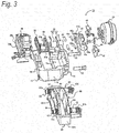
Fig. 3] Fig. 3 is an exploded perspective view showing the configuration of the disc brake apparatus according to the embodiment. - [
Fig. 4] Fig. 4 is a partial exploded perspective view showing a relationship between a unitized pressing force generating mechanism and a caliper body. - [
Fig. 5] Fig. 5 is a partial exploded perspective view showing the configuration of the unitized pressing force generating mechanism. - [
Fig. 6] Fig. 6 is a drawing for explaining an automatic adjusting mechanism. - [
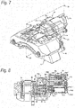
Fig. 7] Fig. 7 is a perspective view showing the configuration of the disc brake apparatus with an actuator configured mechanically. - [
Fig. 8] Fig. 8 is a sectional view showing a section taken on a plane (A)-(B)-(C)-(D) inFig. 7 . - [
Fig. 9] Fig. 9 is a partial exploded perspective view showing the configurations of the mechanically configured actuator and the pressing force generating mechanism. - Hereinafter, an embodiment of a disc brake apparatus of the invention will be described in detail by reference to the drawings. Firstly, referring to
Figs. 1 to 6 , the configuration of a disc brake apparatus according to an embodiment of the invention will described. - A
disc brake apparatus 10 of this embodiment basically includes acaliper body 12, asupport 60 and anactuator 50, andbrake pads rotor 70 to thereby exhibit a braking force. - The
caliper body 12 basically includes a pressingforce generating portion 14, a reactionforce bearing portion 18 andbridge portions 16. The pressingforce generating portion 14 is an element which accommodates a pressingforce generating mechanism 22 including apiston 20 for generating a pressing force. - The reaction
force bearing portion 18 constitutes an element which is disposed so as to be opposite to the pressingforce generating portion 14 across themotor 70 and which bears a pressing force from thepiston 20 when generating a pressing force. A pad holding portion for holding thebrake pad 68 is provided on a surface side of the reactionforce bearing portion 18 which faces therotor 70. - The
bridge portions 16 are elements which straddle an outer circumferential side of therotor 70 to connect the pressingforce generating portion 14 and the reactionforce bearing portion 18 together. - In the
disc brake apparatus 10 according to this embodiment, the pressingforce generating portion 14, the reactionforce bearing portion 18 and thebridge portions 16 make up a frame structure which is formed into a frame when seen in the top view. Because of this, it is possible to enhance rigidity against an axial tension generated by a pressure exerted by thepiston 20. The pressingforce generating portion 14 includes an accommodating portion 14a for accommodating the pressingforce generating mechanism 22. The accommodating portion 14a includes an opening portion on a thick back side of thecaliper body 12, and the pressingforce generating mechanism 22 is designed to be installed through this opening portion. By adopting this construction, the assembling properties of thedisc brake apparatus 10 can be enhanced. - The pressing
force generating mechanism 22 includes thepiston 20, a pressingforce transmission mechanism 24, and acam lever 42. In the case of this embodiment, thepiston 20 has an elliptic pressing surface whose major axis extends in a circumferential direction of themotor 70 and includes twopressing portions 20a in order to ensure a balanced pressing force. A projectingportion 20b is provided at a central portion on a surface of thepiston 20 which is opposite to the surface where thepressing portions 20a are provided, so that the projectingportion 20b can fit into anadjuster screw 32, which will be described in detail later. A through hole having a step portion on a surface side where the pressing portions are formed is provided in a center of the projectingportion 20b, allowing a passage of a fixingbolt 26 therethrough. - The fixing
bolt 26 includes athread portion 26a, aspacer portion 26b and abolt head 26c. Then, portions of the fixingbolt 26 is dimensioned so that thebolt head 26c is accommodated in the step portion, thespacer portion 26b is accommodated in the through hole, and thethread portion 26a projects from the projectingportion 20b. - A
boot 30 for preventing an intrusion of dust is provided between thepiston 20 and a pressing force generatingportion cover 28, which will be described in detail later. - The pressing
force transmission mechanism 24 performs a role of transmitting a pressing force which is generated by operating acam lever 42, which will be described in detail later, to thepiston 20 described above. In the case of this embodiment, the pressingforce transmission mechanism 24 includes theadjuster screw 32 and ahousing 34 as main constituent elements, and anautomatic adjusting mechanism 36 is attached to the pressingforce transmission mechanism 24. - The
adjuster screw 32 is an element for adjusting a gap which is generated when linings on thebrake pads adjuster screw 32 has a cylindrical shape as an external appearance and has a male thread portion on an outer circumferential surface thereof. A partition plate 32a is provided on an inner circumferential side to divide it into a pressing portion and a sliding portion. A recess portion 32b is provided on a pressing portion side of theadjuster screw 32 so that the projecting portion of thepiston 20 loosely fits in the recess portion. A female thread portion 32c is provided in the partition plate 32a so that the thread portion of the fixingbolt 26 can be thread fitted in the female thread portion 32c. The female thread portion 32c may be a through hole or a blind hole as long as it has a depth which allows the fixingbolt 26 to be thread fitted in place therein. By adopting this configuration, thespacer portion 26b is brought into abutment with the partition plate 32a when the fixingbolt 26 is tightened, whereby even when rotating theadjuster screw 32, thepiston 20 maintains its posture without being rotated, and thepiston 20 can be made to follow a behavior of theadjuster screw 32. - On the other hand, a hole 32d is provided on a sliding portion side of the
adjuster screw 32, and this hole 32d is formed so that arotational shaft 40b of anadjuster gear 40 which rotates theadjuster screw 32 is caught. In the embodiment shown inFig. 5 , therotational shaft 40b of theadjuster gear 40, which will be described in detail later, has a hexagonal distal end shape (an engagingportion 40c). Because of this, the hole 32d may be a hole having sides which hold at least two opposite sides of the hexagonal shape. Namely, the hole 32d can have a hexagonal shape, a quadrangular shape or an elliptic shape having two parallel sides, as shown inFig. 5 . - The
housing 34 includes acylindrical portion 34a into which theadjuster screw 32 is thread fitted andpressing portions 34b to which a pressing force is applied. Thecylindrical portion 34a constitutes a holder having a female thread portion on an inner circumferential surface thereof. Thepressing portions 34b constitute arms which are provided on an outer circumference of thecylindrical portion 34a so as to extend therefrom. Thepressing portions 34b are provided in pair so as to be disposed individually on an entrance side and an exit side of therotor 70 which are arranged in the circumferential direction thereof with thecylindrical portion 34a acting as a base point therefor. By adopting the disposing form described above, the application of a biasing force is well balanced, thereby making it possible to prevent the pressingforce transmission mechanism 24 from being prized. A slidinggroove 34c extending along a pressing direction of thebrake pad 66 is provided at a distal end of each of thepressing portions 34b which extend from thecylindrical portion 34a which are proximal ends thereof. The slidinggrooves 34c are grooves which cause thehousing 34 to slide alongguide bolts 52, which will be described in detail later. By providing the slidinggrooves 34c and theguide bolts 52, thehousing 34 can be prevented from being rotated when adjusted. Additionally, by guiding both ends of thehousing 34 in the circumferential direction of therotor 70, it is possible to suppress the application of an unbalanced load generated by a difference in energy between the entrance side and the exit side of therotor 70 occurring when braking tocam portions 42a of thecam lever 42. - The
automatic adjusting mechanism 36 is made up basically of anadjuster lever 38 and theadjuster gear 40. Theadjuster lever 38 is made up of a levermain body 38a and ahook portion 38b. The levermain body 38a constitutes a portion which not only supports thehook portion 38b but also control the behavior of theadjuster lever 38. Arotation base point 38c is provided at one end portion of the levermain body 38a and is fixed rotatably on an outer circumferential portion of thecylindrical portion 34a of thehousing 34. Thehook portion 38b is provided so as to continue to the other end portion of the levermain body 38a. In addition, aspring 38d for adding a tensile force to pull back the levermain body 38a which has been rotated is also attached to the other end portion of the levermain body 38a. Acam groove 38e including inclined surfaces is provided on the levermain body 38a to rotate the levermain body 38a as thehousing 34 moves. Acam piece 48 which is provided at an upper end of abush bearing 46, whose form of disposition will be described later, is brought into abutment with thecam groove 38e. Because of this, the inclined surfaces of thecam groove 38e slide along thecam piece 48 as a result of thehousing 34 moving in a direction indicated by an arrow (a), and the levermain body 38a rotates in a direction indicated by an arrow (b). - The
hook portion 38b is formed so as to be bent from the other end portion of the levermain body 38a in a direction in which theadjuster gear 40, which will be described in detail later, is disposed (towards a lower surface side in this embodiment) so as to mesh with teeth of theadjuster gear 40. - The
adjuster gear 40 is an element for rotating theadjuster screw 32. Theadjuster gear 40 includes a gear main body 40a and therotational shaft 40b. The gear main body 40a is an element which is rotated as a result of a result of theadjuster lever 38 being operated by thehook portion 38b of theadjuster lever 38 being brought into engagement with a plurality of teeth provided on an outer circumference of a disc portion. On the other hand, therotational shaft 40b is an element which is inserted into the hole 32d which is provided on the sliding portion side of theadjuster screw 32 so as to be brought into engagement with an inner wall of the hole 32d to thereby transmit a rotation to theadjuster screw 32. Because of this, anengagement portion 40c is provided on therotational shaft 40 so as to be caught on the inner wall of the hole 32d. In this embodiment, theengagement portion 40c has a hexagonal cross section. - According to the
automatic adjusting mechanism 36 configured in the way described above, as a result of thehousing 34 moving in the direction indicated by the arrow (a) as thecam lever 42 operates, theadjuster lever 38 rotates theadjuster gear 40 to thereby push out theadjuster screw 32. When thehousing 34 is pushed back as a result of the application of a pressing force by thecam lever 42 being released, theadjuster lever 38 is pulled back to its original position by means of the force of thespring 38d. Since the teeth of theadjuster gear 40 are formed into serrations, when thehook portion 38b is pulled back, thehook portion 38b slides on upper portions of the serrations without being caught. Because of this, theadjuster lever 38 is fixed in place with a vertical play given thereto. - The
cam lever 42 includes thecam portions 42a and alever portion 42b. Thecam portions 42 are each made up of an arc-like curved portion, and a thickness of the curved portion is made to differ or change. By configuring thecam portions 42 in this way, a pressing force is generated in a thickness-wise direction of the curved portion by a deviation of a contact portion which is generated when thecam lever 42 is inclined. Namely, thecam lever 42 is configured as a servo mechanism which acts according to a ratio of a length of thelever portion 42b (a length from a rotation center) to a variation in thickness of thecam portion 42a to transform power from theactuator 50, which will be described in detail later, into pressing force. - The
cam lever 42 includes a connecting portion with theactuator 50 at one end portion and includes thecam portions 42a described above at the other end portion. The end portion of thecam lever 42 where thecam portions 42a are disposed is two-pronged so as to straddle thecylindrical portion 34a of thehousing 34 when assembled in place, and thecam portions 42a are disposed individually at ends of the two-pronged portion. As a result of the end portion of thecam lever 42 where thecam portions 42a are disposed being two-pronged, therotational shaft 40b of theadjuster gear 40 of theautomatic adjusting mechanism 36 can be inserted through a center of thecaliper body 12. Additionally, as a result of thecam portions 42a being disposed on an entrance side and an exit side of thecaliper body 12 which are arranged in the circumferential direction of therotor 70, it becomes possible to generate a pressing force in a balanced fashion. - Sliding pins 44 are disposed between the
pressing portions 34b of thehousing 34 and thecam portions 42a of thecam lever 42. Thebush bearings 46 are disposed between thecam portions 42a and an inner wall of the accommodating portion 14a. Pin bushes 44a andcam bushes 46a are provided between the slidingpins 44 and thecam portions 42a and between thecam portions 42a and thebush bearings 46, respectively, so as to enhance the sliding properties between the contact portions. As has been described before, thecam pieces 48 are formed at the upper end of thebush bearings 46 for contact with theadjuster lever 38. - A through hole 14c is provided in a
side wall 14b of the accommodating portion 14a of thecaliper body 12. Theactuator 50 may be an air chamber or the like, for example, and a direct drivenrod 50a is inserted through the through hole 14c of the accommodating portion 14a and is then assembled to thecaliper body 12 in such a state that the direct drivenrod 50a is connected to a distal end of thelever portion 42b of thecam leer 42. Theguide bolts 52 are also assembled from an exterior of theside wall 14b so as to be fixed to thecaliper body 12. - A pressing force generating
portion cover 28 is provided on the opening portion of the accommodating portion 14a so as to cover the pressingforce generating mechanism 22 and seal up the opening portion. The pressing force generatingportion cover 28 includes a side wall which is situated on a side of the accommodating portion 14a where therotor 70 is disposed. As a result of the pressing force generatingportion cover 28 including theside wall 28a, both the accommodating portion 14a and the opening portion of the accommodating portion 14a are opened to an area where therotor 70 is disposed (a rotor disposition side area). This can enhance the assembling properties of the part to be accommodated in the accommodating portion 14a which forms a narrow bottleneck portion. In disposing thepiston 20, parts involved do not have to be inclined so as to be inserted through holes provided in the side wall. This can narrow a clearance between the side wall of the accommodating portion 14a and the parts accommodated therein. This can reduce the size of thecaliper body 12 and allow the parts to be accommodated in the accommodating portion 14a in a highly compact or dense fashion. A throughhole 28b is provided in theside wall 28a so that thepiston 20 disposed in the accommodating portion 14a is passed therethrough into the rotor disposition side area. - The
support 60 is an element for holding thecaliper body 12 described above on to a vehicle or a device main body which is not shown. Thesupport 60 includes at least guide pins 62 and ananchor portion 64. The guide pins 62 are elements for holding thecaliper body 12 so as to slide freely in an axial direction of therotor 70. In this embodiment, the guide pins 62 are disposed in pair both on a pressingforce generating portion 14 side and a reactionforce bearing portion 18 side of thecaliper body 12 so as to correspond to the entrance side and the exit side of therotor 70.Boots 62a are provided individually on the guide pins 62 so as to prevent the adhesion of dust to sliding portions. - The
anchor portion 64 is an element for bearing energy generated in stopping the rotation of therotor 70. In this embodiment, recess portions are provided at portions which correspond to the pressingforce generating portion 14 and the reactionforce bearing portion 18 which correspond, in turn, to both the main surfaces of therotor 70, and thebrake pads support 60 includesbridge portions 60a which connect together the portions which correspond to the two main surfaces of therotor 70. - According to the
disc brake apparatus 10 configured in the way described above, thecam lever 42 is adopted as the servo mechanism, and the reduction in rigidity of thecaliper body 12 can be prevented. The opening portion of the accommodating portion 14a provided in the caliper body is provided on the thick back side of thecaliper body 12, whereby the pressingforce generating mechanism 22 can be assembled in place in the accommodating portion 14a as a unit. This can enhance the efficiency of the assembling work. By attaching theautomatic adjusting mechanism 36, even when thebrake pads rotor 70 is held. - An operation of the
disc brake apparatus 10 configured in the way described above will be described. Firstly, when air introduced into the air chamber, which is theactuator 50, and the direct drivenrod 50a is then pushed out, thecam lever 42 which is connected to the direct drivenrod 50a is inclined in a direction indicated by an arrow (c) about the slidingpins 44 as base points (refer toFig. 2 ). - As the
cam lever 42 is so inclined, the thickness of thecam portions 42a which are situated between thepressing portions 34b of thehousing 34 and thebush bearings 46 shifts from thin to thick. This pushes out the slidingpins 44 by an amount corresponding to the change in thickness in the direction in which therotor 70 is disposed to thereby generate a pressing force. When thebrake pad 66 which is disposed on the pressingforce generating portion 14 side of thecaliper body 12 is brought into abutment with the sliding surface of therotor 70 by means of the pressing force so generated, thecaliper body 12 is caused to slide by means of a reaction force of the pressing force in a direction in which the pressingforce generating portion 14 moves away from therotor 70. This presses thebrake pad 68 which is disposed on the reactionforce bearing portion 18 side against the sliding surface of therotor 70, whereby therotor 70 is held by both of thebrake pads - Here, when the housing moves in the direction indicated by the arrow (a) by means of the generated pressing force (refer to
Fig. 6 ), the adjuster screws 32 rotate by the action of theautomatic adjusting mechanism 36, whereby thepiston 20 is thrust towards the side where therotor 70 is disposed. - When the introduction of air into the air chamber, which is the
actuator 50, is stopped and the direct drivenrod 50a is pulled back, the inclination of thecam lever 42 is also released, whereby thehousing 34 is pushed back to its original position. Through this series of actions, theadjuster lever 38 of theautomatic adjusting mechanism 36 is also returned to its original position by the action of thespring 38d. - In the embodiment described heretofore, the
cam lever 42 is illustrated as being constructed so that thecam portions 42a are curved towards the opposite side to the side where therotor 70 is disposed. However, even in a case where thecam portions 42a are curved towards the side where therotor 70 is disposed, there will be no problem in causing thecom lever 42 to perform as designed. In a case where this construction is adopted, the cam portion needs to be configured so that a lower side of the cam portion forms a thin portion, while an upper side of the cam portion forms a thick portion. - In the embodiment described above, the mechanism and operation of the
actuator 50 are described based on the understanding that theactuator 50 constitutes the air chamber. However, theactuator 50 may be an actuator which operates mechanically with a motor functioning as a power source. Hereinafter, referring toFigs. 7 to 9 , an embodiment will be described in which anactuator 50 is configured as a mechanical one. As to the other configurations than theactuator 50, like reference numerals will be given to elements which are like in function to those described in the embodiment in the drawings, so that a detailed description thereof will be omitted here. This is because there are imposed no specific limitations on the shapes or configurations thereof, as long as they can perform their designed functions. - An actuator 50 shown in
Figs. 7 to 9 (hereinafter, when a description is made by reference to the figures,Fig. 7 represents the figures referred to using an expression, expressing as "shown inFig. 7 ") basically includes anoperating unit 50b and amotor gear unit 50c. Theoperating unit 50b basically includes a ball screw mechanism 50b1, a spring 50b4, guide pins 50b5 and a housing 50b6. - The ball screw mechanism 50b1 has a ball screw 50b2, a base 50b3 which can move in an axial direction of the ball screw 50b2 and a direct driven
rod 50a which is provided so as to extend from the base 50b3 as a base point in the direction of acam lever 42. In the ball screw mechanism 50b1 configured in the way described above, when a force in a rotating direction is applied to the ball screw 50b2, the base 50b3 moves in the axial direction of the ball screw 50b2. On the other hand, when a force in the axial direction of the ball screw 50b2 is applied to the base 50b3, with the ball screw 50b2 made to rotate freely, the ball screw 50b2 rotates as the base 50b3 moves. Then, the direct drivenrod 50a performs a role of pushing out or pulling in thecam lever 42 as the base 50b3 moves. - The spring 50b4 may be a coned disc spring or a coil spring, and performs a role of a biasing mechanism for generating a reaction force in the axial direction of the ball screw 50b2. In the embodiment shown in
Fig. 7 , the spring 50b4 is disposed so as to surround an outer circumference of the ball screw 50b2, and one end portion of the spring 50b4 is in abutment with an end face of the housing 50b6 and the other end portion of the spring 50b4 is in abutment with a main surface of the base 50b3 engaged with the ball screw 50b2. - The guide pins 50b5 are disposed along the axial direction of the ball screw 50b2 and perform a role of guiding the base 50b3 when the base 50b3 moves in the axial direction of the ball screw 50b2. In the embodiment shown in
Fig. 7 , the guide pins 50b5 which are fixed to the housing 50b6 are inserted through penetrating through holes formed in the base 50b3 to perform its designed function. - The housing 50b6 forms an outer shell which accommodates the ball screw mechanism 50b1, the spring 50b4 and the guide pins 50b5 and has a housing main body 50b7 which forms an accommodating portion and a housing cover 50b8 which seals up the housing main body 50b7. In the embodiment shown in
Fig. 7 , the housing cover 50b8 also performs a role of a bracket where theactuator 50 is fixed to acaliper body 12. - The
motor gear unit 50c is a unit for rotting the ball screw 50b2 of theoperating unit 50b. Themotor gear unit 50c has a motor 50c1, a gear unit 50c4 and an electromagnetic clutch 50c5. The motor 50c1 provides a power source for rotating the ball screw 50b2, and in the case of the embodiment shown inFig. 7 , a double shaft motor through which a single rotational shaft penetrates is adopted. One shaft 50c2 extending by way of a body is brought into engagement with the gear unit 50c4, while the other shaft 50c3 is brought into engagement with the electromagnetic clutch 50c5. - There is imposed no specific limitation on the configuration of the gear unit 50c4. However, a configuration may be adopted in which the gear unit 50c4 includes at least a pinion gear which is brought into engagement with the shaft 50c2 of the motor 50c1 and a drive gear which is brought into engagement with the ball screw 50b2 and one or a plurality of speed reduction gears are provided between the pinion gear and the drive gear.
- The electromagnetic clutch 50c5 is an element for stopping a free rotation of the rotational shaft of the motor 50c1. Thus, the electromagnetic clutch 50c5 may be configured so that the electromagnetic clutch 50c5 is in engagement with the other shaft 50c3 of the motor 50c1 so as to stop a free rotation of the rotational shaft when electric power is supplied thereto. The provision of the electromagnetic clutch 50c5 obviates the necessity of keeping the application of a load to the motor 50c1 at all times while the brake is released. The
motor gear unit 50c is covered externally by the housing 50c6. - According to the
motor gear unit 50c configured in the way described above, the ball screw 50b2 is rotated by driving the motor 50c1, and the base 50b3 is drawn towards the gear unit 50c4 (that is, in a direction in which the spring 50b4 is compressed). On the other hand, when the supply of electric power to the motor 50c1 is stopped, the rotational shaft of the motor 50c1 becomes free to rotate. The spring 50b4 which is compressed by the rotation of the ball screw 50b2 generates a reaction force between the base 50b3 and the housing 50b6 to thereby generate a force with which the base 50b3 is pushed back in a direction in which the base 50b3 is moved away from the gear unit 50c4. The rotational shaft of the motor 50c1 becomes free to rotate, and a resisting force against a spring-back force of the spring 50b4 is small. Because of this, the base 50b3 moves in the direction in which it moves away from the gear unit 50c4 while rotating reversely the ball screw 50b2. - Here, when the electromagnetic clutch 50c5 is actuated with the spring 50b4 compressed, the free rotation of the rotational shaft of the motor 50c1 is interrupted. Because of this, even when the supply of electric power to the motor 50c1 is stopped, there is no risk of the base 50b3 being pushed back.
- In the embodiment shown in
Fig. 7 , thecam lever 42 and the direct drivenrod 50a are described as being connected together via a connectingmember 50d. In a case where theactuator 50 is configured like this, with both the motor 50c1 and the electromagnetic clutch 50c5 staying in an inoperable state, the base 50b3 is pressed in a direction in which the base 50b3 moves away from the gear unit 50c4 by means of the force of the spring 50b4. In this state, thecam lever 42 connected to the direct drivenrod 50a which extends from the base 50b3 is inclined in a direction in which the brake is actuated. - In contrast with this, when the motor 50c1 is driven, the ball screw 50b2 is rotated, and the base 50b3 moves in such a way as to be drawn towards the gear unit 50c4. This pulls back the
cam lever 42 in a direction in which the brake is released. By actuating the electromagnetic clutch 50c5 in this state, even when the supply of electric power to the motor 50c1 is stopped, the brake can be held released. - When the brake is applied from the state where the brake is released, the electromagnetic clutch 50c5 is released, and the motor 50c1 is actuated to rotate reversely to the direction in which the spring 50b4 is compressed, whereby a time spent until the brake is actuated can be shortened, thereby making it possible to realize an improved response.
- Even when the
actuator 50 is configured in the way described above, the same working effects as those provided by thedisc brake apparatus 10 according to the embodiment can be obtained. - Here, the characteristics of the embodiments of the disc brake apparatus according to the invention will be summarized as below on an item-by-item basis.
- [1] A disc brake apparatus (10) including:
- a caliper body (12) having a frame structure, wherein
- the caliper body includes an accommodating portion (14a) which accommodates at least:
- a piston (20) which presses on a brake pad (66, 68),
- a cam lever (42) which generates a pressing force through rotation, and
- a pressing force transmission mechanism (24) which is interposed between the piston and the cam lever and transmits the pressing force to the piston,
- the accommodating portion has an opening which enables the piston, the cam lever and the pressing force transmission mechanism to be assembled into the caliper body from a thick back side of the caliper body, and
- both the accommodating portion and the opening portion are opened to a rotor disposing side area of the caliper body.
- [2] The disc brake apparatus (10) according to [1] above, including:
- a pressing force generating portion cover (28) which seals up the opening portion, wherein
- a side wall (14b) which separates the accommodating portion from the rotor disposing side area is provided on the pressing force generating portion cover, and
- a through hole (14c) through which the piston is inserted into the rotor disposing side area is provided in the side wall.
- [3] The disc brake apparatus according to [1] or [2] above, including:
- an actuator (50) which actuates the cam lever, wherein
- the actuator includes a direct driven rod (50a) which is brought into engagement with the cam lever, and
- the actuator is an air chamber which actuates the direct driven rod by means of a force of air.
- [4] The disc brake apparatus according to [1] or [2] above, including:
- an actuator which actuates the cam lever, wherein
- the actuator includes a direct driven rod which is brought into engagement with the cam lever, and
- the disc brake apparatus includes a biasing mechanism (a spring 50b4) which inclines the cam lever to a brake applying side via the direct driven rod and a motor gear unit (50c) which inclines the cam lever to a brake releasing side.
- [5] The disc brake apparatus according to [4] above, wherein
the direct driven rod extends from a base (50b3) of a ball screw mechanism (50b1) which includes the base (50b3) to be pressed against by the biasing mechanism and a ball screw (50b2) to be rotated by the motor gear unit to move the base in an axial direction. - [6] The disc brake apparatus according to [5] above, wherein
the motor gear unit includes an electromagnetic clutch (50c5) which frees a rotation of a rotational shaft (the other shaft 50c3) of a motor (50c1). - [7] The disc brake apparatus according to any one of [1] to [6] above, wherein
the cam lever (42) has a two-pronged construction in which the cam lever straddles the pressing force transmission mechanism, and
a cam portion (42a) is provided at a distal end side of each of two-pronged portions of the cam lever (42). - [8] The disc brake apparatus according to any one of [1] to [7] above, wherein
the pressing force transmission mechanism includes an adjuster screw (32) which adjustes a thrust position of the piston and a housing (34) which covers the adjuster screw and receives the pressing force. - [9] The disc brake apparatus according [8], wherein
a sliding groove (34c) extending along a pressing direction of the brake pad is provided on at least a portion of the housing, and
a guide bolt (52) which is fixed to the caliper body is disposed along the sliding groove. - [10] The disc brake apparatus according to [8] or [9], wherein
an automatic adjusting mechanism (36) which performs a position adjustment by the adjuster screw using a stroke of the housing is attached to the pressing force transmission mechanism (24). - [11] The disc brake apparatus according to any one of [8] to [10] including [3], wherein
a sliding pin (44) is disposed between a cam portion of the cam lever and the housing. - The invention is not limited to the embodiments that have been described heretofore and hence can be modified or improved as required. In addition, the materials, shapes or configurations, dimensions, numbers and locations of the constituent elements described in the embodiments are arbitrary and are not limited thereto, as long as the invention can be attained.
- In addition, this patent application is based on Japanese Patent Application (No.
2015-090566) filed on April 27, 2015 2015-221212) filed on November 11, 2015 - According to the disc brake system of the invention, even when the cam lever is adopted for use in the servo mechanism, it is possible to prevent a reduction in body rigidity. Additionally, it is possible to provide the disc brake apparatus which enhances the efficiency of the assembling work of the cam lever and the pressing force transmission mechanism.
- 10 disc brake apparatus; 12 caliper body; 14 pressing force generating portion; 14a accommodating portion; 14b side wall; 14c through hole; 16 bridge portion; 18 reaction force bearing portion; 20 piston; 20a pressing portion; 20b projecting portion; 22 pressing force generating mechanism; 24 pressing force transmission mechanism; 26 fixing bolt; 26a thread portion; 20b spacer portion; 26c bolt head; 28 pressing force generating portion cover; 28a side wall; 28b through hole; 30 boot; 32 adjuster screw; 32a partition plate; 32b recess portion; 32c female thread portion; 32d hole; 34 housing; 34a cylindrical portion; 34b pressing portion; 34c sliding groove; 36 automatic adjusting mechanism; 38 adjuster lever; 38a lever main body; 38b hook portion; 38c rotational base point; 38d spring; 38e cam groove; 40 adjuster gear; 40a gear main body; 40b rotational shaft; 40c engaging portion; 42 cam lever; 42a cam portion; 42b lever portion; 44 sliding pin; 44a pin bush; 46 bush bearing; 46a cam bush; 48 cam piece; 50 actuator; 50a direct driven rod; 50b operating unit; 50b1 ball screw mechanism; 50b2 ball screw; 50b3 base; 50b4 spring; 50b5 guide pin; 50b6 housing; 50b7 housing main body; 50b8 housing cover; 50c motor gear unit; 50c1 motor; 50c2 one shaft; 50c3 the other shaft; 50c4 gear unit; 50c5 electromagnetic clutch; 50c6 housing; 50d connecting member; 52 guide bolt; 60 support; 60a bridge portion; 62 guide pin; 62a boot; 64 anchor portion; 66, 68 brake pad; 70 rotor.
Claims (11)
- A disc brake apparatus comprising:a caliper body having a frame structure, whereinthe caliper body includes an accommodating portion which accommodates at least:a piston which presses on a brake pad,a cam lever which generates a pressing force through rotation, anda pressing force transmission mechanism which is interposed between the piston and the cam lever and transmits the pressing force to the piston,the accommodating portion has an opening which enables the piston, the cam lever and the pressing force transmission mechanism to be assembled into the caliper body from a thick back side of the caliper body, andboth the accommodating portion and the opening portion are opened to a rotor disposing side area of the caliper body.
- The disc brake apparatus according to Claim 1, comprising:a pressing force generating portion cover which seals up the opening portion, whereina side wall which separates the accommodating portion from the rotor disposing side area is provided on the pressing force generating portion cover, anda through hole through which the piston is inserted into the rotor disposing side area is provided in the side wall.
- The disc brake apparatus according to Claim 1 or 2, comprising:an actuator which actuates the cam lever, whereinthe actuator includes a direct driven rod which is brought into engagement with the cam lever, andthe actuator is an air chamber which actuates the direct driven rod by means of a force of air.
- The disc brake apparatus according to Claim 1 or 2, comprising:an actuator which actuates the cam lever, whereinthe actuator includes a direct driven rod which is brought into engagement with the cam lever, andthe disc brake apparatus includes a biasing mechanism which inclines the cam lever to a brake applying side via the direct driven rod and a motor gear unit which inclines the cam lever to a brake releasing side.
- The disc brake apparatus according to Claim 4, wherein
the direct driven rod extends from a base of a ball screw mechanism which includes the base to be pressed against by the biasing mechanism and a ball screw to be rotated by the motor gear unit to move the base in an axial direction. - The disc brake apparatus according to Claim 5, wherein
the motor gear unit includes an electromagnetic clutch which frees a rotation of a rotational shaft of a motor. - The disc brake apparatus according to any one of Claims 1 to 6, wherein
the cam lever has a two-pronged construction in which the cam lever straddles the pressing force transmission mechanism, and
a cam portion is provided at a distal end side of each of two-pronged portions of the cam lever. - The disc brake apparatus according to any one of Claims 1 to 7, wherein
the pressing force transmission mechanism includes an adjuster screw which adjusts a thrust position of the piston and a housing which covers the adjuster screw and receives the pressing force. - The disc brake apparatus according to Claim 8, wherein
a sliding groove extending along a pressing direction of the brake pad is provided on at least a portion of the housing, and
a guide bolt which is fixed to the caliper body is disposed along the sliding groove. - The disc brake apparatus according to Claim 8 or 9, wherein
an automatic adjusting mechanism which performs a position adjustment by the adjuster screw using a stroke of the housing is attached to the pressing force transmission mechanism. - The disc brake apparatus according to any one of Claims 8 to 10 including Claim 3, wherein
a sliding pin is disposed between a cam portion of the cam lever and the housing.
Applications Claiming Priority (3)
| Application Number | Priority Date | Filing Date | Title |
|---|---|---|---|
| JP2015090566 | 2015-04-27 | ||
| JP2015221212A JP6572102B2 (en) | 2015-04-27 | 2015-11-11 | Disc brake device |
| PCT/JP2016/062573 WO2016175107A1 (en) | 2015-04-27 | 2016-04-20 | Disc brake apparatus |
Publications (2)
| Publication Number | Publication Date |
|---|---|
| EP3290734A1 true EP3290734A1 (en) | 2018-03-07 |
| EP3290734A4 EP3290734A4 (en) | 2018-12-19 |
Family
ID=57489373
Family Applications (1)
| Application Number | Title | Priority Date | Filing Date |
|---|---|---|---|
| EP16786384.4A Withdrawn EP3290734A4 (en) | 2015-04-27 | 2016-04-20 | Disc brake apparatus |
Country Status (4)
| Country | Link |
|---|---|
| US (1) | US10527114B2 (en) |
| EP (1) | EP3290734A4 (en) |
| JP (1) | JP6572102B2 (en) |
| CN (1) | CN107532662B (en) |
Families Citing this family (4)
| Publication number | Priority date | Publication date | Assignee | Title |
|---|---|---|---|---|
| JP2019015337A (en) | 2017-07-06 | 2019-01-31 | 曙ブレーキ工業株式会社 | Disc brake device |
| US10677303B2 (en) * | 2018-02-06 | 2020-06-09 | Bendix Spicer Foundation Brake Llc | Disc brake wear adjuster |
| EP3564552B1 (en) | 2018-04-30 | 2021-06-02 | Meritor Heavy Vehicle Braking Systems (UK) Limited | An actuation mechanism |
| CN117006176B (en) * | 2022-04-27 | 2025-09-09 | 台湾三嵩工业有限公司 | Brake device for power failure |
Family Cites Families (24)
| Publication number | Priority date | Publication date | Assignee | Title |
|---|---|---|---|---|
| AT286120B (en) | 1968-06-21 | 1970-11-25 | Heinkel Ag Ernst | Partly lined disc brake |
| SE376283B (en) | 1969-07-11 | 1975-05-12 | Ferodo Sa | |
| US3612226A (en) | 1969-10-08 | 1971-10-12 | Bendix Corp | Caliper brake housing support and shoe antirattle spring |
| JPS5498461A (en) | 1978-01-19 | 1979-08-03 | Sumitomo Electric Ind Ltd | Disc brake |
| DE4308704A1 (en) * | 1993-03-18 | 1994-09-22 | Knorr Bremse Ag | Air operated disc brake |
| DE19515063C2 (en) * | 1995-04-27 | 2002-06-06 | Knorr Bremse Systeme | Disc brake for vehicles, in particular road vehicles |
| JP3844312B2 (en) | 1996-06-11 | 2006-11-08 | 曙ブレーキ工業株式会社 | Manual adjustment mechanism for parking brake type parking brake |
| DE19642384C2 (en) | 1996-10-14 | 2002-02-21 | Knorr Bremse Systeme | Air-operated commercial vehicle disc brake |
| SE516513C2 (en) | 2000-05-31 | 2002-01-22 | Haldex Brake Prod Ab | Disc brake comprising a braking mechanism |
| SE522332C2 (en) | 2000-05-31 | 2004-02-03 | Haldex Brake Prod Ab | Method of mounting a brake mechanism in a caliper and such caliper |
| SE516495C2 (en) | 2000-05-31 | 2002-01-22 | Haldex Brake Prod Ab | Brake mechanism and caliper for a disc brake |
| SE522395C2 (en) | 2000-05-31 | 2004-02-03 | Haldex Brake Prod Ab | Modular brake mechanism |
| SE523552C2 (en) | 2000-05-31 | 2004-04-27 | Haldex Brake Prod Ab | Brake mechanism and a method for controlling the power gain |
| US7175006B2 (en) * | 2004-05-18 | 2007-02-13 | Bendix Spicer Foundation Brake Llc | Apparatus and method for sensing disc brake actuator position |
| DE102006029942A1 (en) * | 2006-01-12 | 2007-08-02 | Knorr-Bremse Systeme für Nutzfahrzeuge GmbH | Self-energizing disc brake with electromechanical actuator |
| ITMI20061973A1 (en) * | 2006-10-13 | 2008-04-14 | Freni Brembo Spa | BRAKE CALIPER WITH DISC |
| JP4741692B2 (en) | 2009-06-23 | 2011-08-03 | 本田技研工業株式会社 | Opposite piston type caliper body |
| CN101660505A (en) | 2009-09-23 | 2010-03-03 | 南方天合底盘系统有限公司 | Brake caliper assembly of normally open type wind driven generator main shaft system |
| JP5570174B2 (en) * | 2009-10-08 | 2014-08-13 | 株式会社ショーワ | Piston for hydraulic shock absorber |
| JP5366753B2 (en) | 2009-10-09 | 2013-12-11 | 日野自動車株式会社 | Disc brake device |
| DE102010005909C5 (en) * | 2010-01-27 | 2017-02-16 | Wabco Europe Bvba-Sprl | Disc brake, in particular for commercial vehicles |
| DE102012006113A1 (en) | 2012-03-26 | 2013-09-26 | Knorr-Bremse Systeme für Nutzfahrzeuge GmbH | Clamping device for a lever-operated disc brake |
| DE202013102651U1 (en) | 2013-01-09 | 2013-07-25 | Knorr-Bremse Systeme für Nutzfahrzeuge GmbH | Disc brake for a commercial vehicle |
| KR101808397B1 (en) * | 2013-03-11 | 2017-12-13 | 할덱스 브레이크 프로덕츠 에이비 | Disc brake, brake actuation mechanism for such a disc brake and method for brake adjustment |
-
2015
- 2015-11-11 JP JP2015221212A patent/JP6572102B2/en not_active Expired - Fee Related
-
2016
- 2016-04-20 CN CN201680024851.7A patent/CN107532662B/en not_active Expired - Fee Related
- 2016-04-20 US US15/569,223 patent/US10527114B2/en not_active Expired - Fee Related
- 2016-04-20 EP EP16786384.4A patent/EP3290734A4/en not_active Withdrawn
Also Published As
| Publication number | Publication date |
|---|---|
| EP3290734A4 (en) | 2018-12-19 |
| CN107532662A (en) | 2018-01-02 |
| JP6572102B2 (en) | 2019-09-04 |
| CN107532662B (en) | 2019-10-15 |
| US20180298962A1 (en) | 2018-10-18 |
| JP2016205613A (en) | 2016-12-08 |
| US10527114B2 (en) | 2020-01-07 |
Similar Documents
| Publication | Publication Date | Title |
|---|---|---|
| KR101980225B1 (en) | Disk brake with a parking brake, mechanical thrust assembly, and method of assembling | |
| US10527114B2 (en) | Disc brake apparatus | |
| JP2004263874A (en) | Lever system | |
| EP3236099A1 (en) | Disc brake device | |
| CN106662179A (en) | Disc brake and brake actuation mechanism for a disc brake | |
| KR20090057057A (en) | Combined vehicle brakes with electromechanical driven parking brakes and gears that convert rotational motion into translational motion | |
| KR20150084936A (en) | Planet carrier for an electromechanical actuator of a parking brake, actuator and assembly methods | |
| CN102003477B (en) | Disk type braker | |
| JP5334571B2 (en) | Wheel brake | |
| US3741350A (en) | Actuating and returning devices for disc brakes | |
| CN111356857B (en) | Braking device | |
| JP2014228111A (en) | Disc brake device | |
| JP2011074946A (en) | Disc brake | |
| KR101292623B1 (en) | Clutch actuator with wear compensation function | |
| WO2016175107A1 (en) | Disc brake apparatus | |
| WO2015098782A1 (en) | Disc brake device | |
| US8250967B2 (en) | Automatic transmission servo | |
| JPH1122764A (en) | Adjuster for disc brake device | |
| WO2018199114A1 (en) | Disc brake device | |
| JP2017088049A (en) | Brake system for vehicle | |
| JP6641881B2 (en) | Vehicle brakes | |
| JP6364236B2 (en) | Disc brake device | |
| KR20210083672A (en) | Electromechanical brake | |
| GB1506852A (en) | Vehicle brake actuators | |
| JP4863021B2 (en) | Disc brake device |
Legal Events
| Date | Code | Title | Description |
|---|---|---|---|
| STAA | Information on the status of an ep patent application or granted ep patent |
Free format text: STATUS: THE INTERNATIONAL PUBLICATION HAS BEEN MADE |
|
| PUAI | Public reference made under article 153(3) epc to a published international application that has entered the european phase |
Free format text: ORIGINAL CODE: 0009012 |
|
| STAA | Information on the status of an ep patent application or granted ep patent |
Free format text: STATUS: REQUEST FOR EXAMINATION WAS MADE |
|
| 17P | Request for examination filed |
Effective date: 20171027 |
|
| AK | Designated contracting states |
Kind code of ref document: A1 Designated state(s): AL AT BE BG CH CY CZ DE DK EE ES FI FR GB GR HR HU IE IS IT LI LT LU LV MC MK MT NL NO PL PT RO RS SE SI SK SM TR |
|
| AX | Request for extension of the european patent |
Extension state: BA ME |
|
| DAV | Request for validation of the european patent (deleted) | ||
| DAX | Request for extension of the european patent (deleted) | ||
| A4 | Supplementary search report drawn up and despatched |
Effective date: 20181121 |
|
| RIC1 | Information provided on ipc code assigned before grant |
Ipc: F16D 121/08 20120101ALI20181115BHEP Ipc: F16D 125/32 20120101ALI20181115BHEP Ipc: F16D 55/226 20060101AFI20181115BHEP Ipc: F16D 65/56 20060101ALI20181115BHEP Ipc: F16D 65/18 20060101ALI20181115BHEP Ipc: F16D 65/02 20060101ALI20181115BHEP |
|
| STAA | Information on the status of an ep patent application or granted ep patent |
Free format text: STATUS: EXAMINATION IS IN PROGRESS |
|
| 17Q | First examination report despatched |
Effective date: 20211104 |
|
| GRAP | Despatch of communication of intention to grant a patent |
Free format text: ORIGINAL CODE: EPIDOSNIGR1 |
|
| STAA | Information on the status of an ep patent application or granted ep patent |
Free format text: STATUS: GRANT OF PATENT IS INTENDED |
|
| INTG | Intention to grant announced |
Effective date: 20220721 |
|
| STAA | Information on the status of an ep patent application or granted ep patent |
Free format text: STATUS: THE APPLICATION IS DEEMED TO BE WITHDRAWN |
|
| 18D | Application deemed to be withdrawn |
Effective date: 20221201 |