EP3290708A1 - Peristaltic motor and pump combination - Google Patents
Peristaltic motor and pump combination Download PDFInfo
- Publication number
- EP3290708A1 EP3290708A1 EP17189711.9A EP17189711A EP3290708A1 EP 3290708 A1 EP3290708 A1 EP 3290708A1 EP 17189711 A EP17189711 A EP 17189711A EP 3290708 A1 EP3290708 A1 EP 3290708A1
- Authority
- EP
- European Patent Office
- Prior art keywords
- pump
- motor
- tube
- rotor
- fluid
- Prior art date
- Legal status (The legal status is an assumption and is not a legal conclusion. Google has not performed a legal analysis and makes no representation as to the accuracy of the status listed.)
- Granted
Links
Images

Classifications
-
- F—MECHANICAL ENGINEERING; LIGHTING; HEATING; WEAPONS; BLASTING
- F04—POSITIVE - DISPLACEMENT MACHINES FOR LIQUIDS; PUMPS FOR LIQUIDS OR ELASTIC FLUIDS
- F04B—POSITIVE-DISPLACEMENT MACHINES FOR LIQUIDS; PUMPS
- F04B43/00—Machines, pumps, or pumping installations having flexible working members
- F04B43/12—Machines, pumps, or pumping installations having flexible working members having peristaltic action
- F04B43/1253—Machines, pumps, or pumping installations having flexible working members having peristaltic action by using two or more rollers as squeezing elements, the rollers moving on an arc of a circle during squeezing
-
- B—PERFORMING OPERATIONS; TRANSPORTING
- B64—AIRCRAFT; AVIATION; COSMONAUTICS
- B64G—COSMONAUTICS; VEHICLES OR EQUIPMENT THEREFOR
- B64G1/00—Cosmonautic vehicles
- B64G1/22—Parts of, or equipment specially adapted for fitting in or to, cosmonautic vehicles
- B64G1/60—Crew or passenger accommodations
-
- C—CHEMISTRY; METALLURGY
- C02—TREATMENT OF WATER, WASTE WATER, SEWAGE, OR SLUDGE
- C02F—TREATMENT OF WATER, WASTE WATER, SEWAGE, OR SLUDGE
- C02F1/00—Treatment of water, waste water, or sewage
- C02F1/66—Treatment of water, waste water, or sewage by neutralisation; pH adjustment
-
- C—CHEMISTRY; METALLURGY
- C02—TREATMENT OF WATER, WASTE WATER, SEWAGE, OR SLUDGE
- C02F—TREATMENT OF WATER, WASTE WATER, SEWAGE, OR SLUDGE
- C02F1/00—Treatment of water, waste water, or sewage
- C02F1/68—Treatment of water, waste water, or sewage by addition of specified substances, e.g. trace elements, for ameliorating potable water
- C02F1/685—Devices for dosing the additives
- C02F1/686—Devices for dosing liquid additives
-
- F—MECHANICAL ENGINEERING; LIGHTING; HEATING; WEAPONS; BLASTING
- F03—MACHINES OR ENGINES FOR LIQUIDS; WIND, SPRING, OR WEIGHT MOTORS; PRODUCING MECHANICAL POWER OR A REACTIVE PROPULSIVE THRUST, NOT OTHERWISE PROVIDED FOR
- F03C—POSITIVE-DISPLACEMENT ENGINES DRIVEN BY LIQUIDS
- F03C7/00—Engines of flexible-wall type
-
- F—MECHANICAL ENGINEERING; LIGHTING; HEATING; WEAPONS; BLASTING
- F04—POSITIVE - DISPLACEMENT MACHINES FOR LIQUIDS; PUMPS FOR LIQUIDS OR ELASTIC FLUIDS
- F04B—POSITIVE-DISPLACEMENT MACHINES FOR LIQUIDS; PUMPS
- F04B15/00—Pumps adapted to handle specific fluids, e.g. by selection of specific materials for pumps or pump parts
- F04B15/04—Pumps adapted to handle specific fluids, e.g. by selection of specific materials for pumps or pump parts the fluids being hot or corrosive
-
- F—MECHANICAL ENGINEERING; LIGHTING; HEATING; WEAPONS; BLASTING
- F04—POSITIVE - DISPLACEMENT MACHINES FOR LIQUIDS; PUMPS FOR LIQUIDS OR ELASTIC FLUIDS
- F04B—POSITIVE-DISPLACEMENT MACHINES FOR LIQUIDS; PUMPS
- F04B43/00—Machines, pumps, or pumping installations having flexible working members
- F04B43/12—Machines, pumps, or pumping installations having flexible working members having peristaltic action
-
- C—CHEMISTRY; METALLURGY
- C02—TREATMENT OF WATER, WASTE WATER, SEWAGE, OR SLUDGE
- C02F—TREATMENT OF WATER, WASTE WATER, SEWAGE, OR SLUDGE
- C02F2103/00—Nature of the water, waste water, sewage or sludge to be treated
- C02F2103/005—Black water originating from toilets
-
- C—CHEMISTRY; METALLURGY
- C02—TREATMENT OF WATER, WASTE WATER, SEWAGE, OR SLUDGE
- C02F—TREATMENT OF WATER, WASTE WATER, SEWAGE, OR SLUDGE
- C02F2201/00—Apparatus for treatment of water, waste water or sewage
- C02F2201/001—Build in apparatus for autonomous on board water supply and wastewater treatment (e.g. for aircrafts, cruiseships, oil drilling platforms, railway trains, space stations)
-
- F—MECHANICAL ENGINEERING; LIGHTING; HEATING; WEAPONS; BLASTING
- F04—POSITIVE - DISPLACEMENT MACHINES FOR LIQUIDS; PUMPS FOR LIQUIDS OR ELASTIC FLUIDS
- F04B—POSITIVE-DISPLACEMENT MACHINES FOR LIQUIDS; PUMPS
- F04B2205/00—Fluid parameters
- F04B2205/01—Pressure before the pump inlet
Definitions
- This application relates to a peristaltic pump that is driven by a peristaltic motor.
- a peristaltic pump In a common peristaltic pump, a rotor carries a plurality of rollers, which are moved along a tube. A fluid to be moved is received in the tube. The rollers pinch the tube and as they rotate along the tube, they move the fluid from an inlet to an outlet.
- One such system is a urine treatment system for use on a spacecraft.
- the water in the urine must be purified for reuse. It is known to deliver urine into a container.
- the urine is mixed with a quantity of water and an acid. This is part of the treatment for separating the water from the urine such that it can be reused.
- a peristaltic pump system has a pump tube and a rotor engaging the pump tube.
- the rotor is drivable to rotate to move a fluid through the pump tube from a pump inlet to a pump outlet.
- a motor drives the pump rotor to rotate.
- the motor includes a motor tube and a motor rotor to be driven to rotate by a fluid moving through the motor tube.
- a urine treatment system and method are also disclosed.
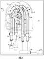
- a water treatment system 20, such as may be utilized on a spacecraft 19, includes a combined peristaltic motor and pump 22.
- a surrounding housing 23 is shown in phantom.
- a toilet 24 is shown schematically and will deliver urine into a container 26.
- a water outlet 28 delivers a quantity of water into the container 26.
- An acid outlet 30 also delivers an acid into the container 26. It may be that the acid from outlet 30 and water from outlet 28 mix before reaching the container 26.
- the use of the combined water and acid to treat the urine and removed water from the urine is generally as known.
- An acid inlet 32 receives an acid from a source 34.
- a water supply 36 delivers pressurized water into a motor inlet 38.
- a main source of drive would be pressurized water.
- the combined peristaltic pump and motor 22 provide valuable benefits in that the pressurized water is utilized as a driving force for the acid pump as will be explained below.
- the water source 36 is the potable water for the spacecraft, it is important to keep the acid and water separate until being mixed.
- the combined peristaltic pump and motor 22 achieve this goal.
- a motor tube 40 is shown along with a rotor 42.
- Rotor 42 rotates and moves rollers 44 along a length of the tube 40.
- Another tube 46 is a pump tube. Rollers 48 from a pump rotor (not shown in this figure) move along the tube 46.
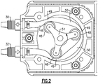
- FIG. 2 shows the operation of the peristaltic pump for moving the acid.
- the rotor 51 is driven to rotate the rollers 48.
- the rollers pinch the tube as shown at 49.
- Intermediate the tube pinch points 49 is a pumping chamber 50.
- Fluid to be moved is trapped in the chamber 50 between the two pinch points 49.
- the fluid in the pump is acid and will be maintained separate from the fluid in the motor, potable water, since each fluid is received in its respective tubes.
- the motor side works in the opposed direction. That is, pressurized water is directed into the inlet 38 and will drive the motor rotor 42 by causing the pinch points between the rollers 44 to drive the rollers 44 and hence the rotor 42 to rotate.
- pressurized water moves from its inlet 38 to its outlet 28, it causes the rotor 42 to rotate. This, in turn, causes the pump rotor 51 to rotate.
- FIG. 3 shows further details.
- a connecting shaft 60 connects rotors 42 and 51.
- the tubes 40 and 46 are shown as well as the rollers 44 and 48 and rotors 42 and 51.
- a combined peristaltic pump and motor is provided to drive a fluid from an inlet to an outlet.
Landscapes
- Engineering & Computer Science (AREA)
- Mechanical Engineering (AREA)
- General Engineering & Computer Science (AREA)
- Chemical & Material Sciences (AREA)
- Environmental & Geological Engineering (AREA)
- Life Sciences & Earth Sciences (AREA)
- Hydrology & Water Resources (AREA)
- Water Supply & Treatment (AREA)
- Organic Chemistry (AREA)
- Remote Sensing (AREA)
- Aviation & Aerospace Engineering (AREA)
- Medicinal Chemistry (AREA)
- Health & Medical Sciences (AREA)
- Combustion & Propulsion (AREA)
- External Artificial Organs (AREA)
- Reciprocating Pumps (AREA)
Abstract
Description
- This application relates to a peristaltic pump that is driven by a peristaltic motor.
- Many types of pumps have been developed for different applications. One type of pump, which may be utilized to move a harsh fluid, is a peristaltic pump. In a common peristaltic pump, a rotor carries a plurality of rollers, which are moved along a tube. A fluid to be moved is received in the tube. The rollers pinch the tube and as they rotate along the tube, they move the fluid from an inlet to an outlet.
- It has also been proposed to utilize a peristaltic system such as described above, but in a reverse operation as a motor. However, a peristaltic motor has never been proposed to drive a peristaltic pump.
- Again, many systems utilize pumps. One such system is a urine treatment system for use on a spacecraft. In such a system, the water in the urine must be purified for reuse. It is known to deliver urine into a container. The urine is mixed with a quantity of water and an acid. This is part of the treatment for separating the water from the urine such that it can be reused.
- Systems for moving the water and metering the acid are somewhat complicated.
- A peristaltic pump system has a pump tube and a rotor engaging the pump tube. The rotor is drivable to rotate to move a fluid through the pump tube from a pump inlet to a pump outlet. A motor drives the pump rotor to rotate. The motor includes a motor tube and a motor rotor to be driven to rotate by a fluid moving through the motor tube.
- A urine treatment system and method are also disclosed.
- These and other features may be best understood from the following drawings and specification.
-
-
Figure 1 shows a water treatment system. -
Figure 2 shows a feature of a peristaltic pump. -
Figure 3 shows details of the combined peristaltic pump and motor. - A
water treatment system 20, such as may be utilized on aspacecraft 19, includes a combined peristaltic motor andpump 22. A surroundinghousing 23 is shown in phantom. Atoilet 24 is shown schematically and will deliver urine into acontainer 26. A water outlet 28 delivers a quantity of water into thecontainer 26. Anacid outlet 30 also delivers an acid into thecontainer 26. It may be that the acid fromoutlet 30 and water from outlet 28 mix before reaching thecontainer 26. The use of the combined water and acid to treat the urine and removed water from the urine is generally as known. - An
acid inlet 32 receives an acid from asource 34. Awater supply 36 delivers pressurized water into amotor inlet 38. - In a spacecraft application, a main source of drive would be pressurized water. As such, the combined peristaltic pump and
motor 22 provide valuable benefits in that the pressurized water is utilized as a driving force for the acid pump as will be explained below. - Since the
water source 36 is the potable water for the spacecraft, it is important to keep the acid and water separate until being mixed. The combined peristaltic pump andmotor 22 achieve this goal. - A
motor tube 40 is shown along with arotor 42.Rotor 42 rotates and movesrollers 44 along a length of thetube 40. Anothertube 46 is a pump tube.Rollers 48 from a pump rotor (not shown in this figure) move along thetube 46. -
Figure 2 shows the operation of the peristaltic pump for moving the acid. As shown, therotor 51 is driven to rotate therollers 48. The rollers pinch the tube as shown at 49. Intermediate thetube pinch points 49 is apumping chamber 50. Fluid to be moved is trapped in thechamber 50 between the twopinch points 49. As therotor 51 continues to rotate, the fluid is moved from theinlet 32 toward theoutlet 30. As can be appreciated, the fluid in the pump is acid and will be maintained separate from the fluid in the motor, potable water, since each fluid is received in its respective tubes. - The motor side works in the opposed direction. That is, pressurized water is directed into the
inlet 38 and will drive themotor rotor 42 by causing the pinch points between therollers 44 to drive therollers 44 and hence therotor 42 to rotate. Thus, as the pressurized water moves from itsinlet 38 to its outlet 28, it causes therotor 42 to rotate. This, in turn, causes thepump rotor 51 to rotate. - Since the water driving the motor is being delivered into a container along with the
rotor 51 driving the acid, this facilitates the metering of the two fluids. -
Figure 3 shows further details. A connectingshaft 60 connectsrotors tubes rollers rotors - Thus, a combined peristaltic pump and motor is provided to drive a fluid from an inlet to an outlet.
- Although an embodiment of this invention has been disclosed, a worker of ordinary skill in this art would recognize that certain modifications would come within the scope of this invention. For that reason, the following claims should be studied to determine the true scope and content of this invention.
Claims (13)
- A peristaltic pump system (22) comprising:a pump tube (46) and a pump rotor (51) engaging said pump tube (46), said pump rotor (51) being drivable to rotate to move a pump fluid through said pump tube (46) from a pump inlet (32) to a pump outlet (30); anda motor for driving said pump rotor (51) to rotate, said motor including a motor tube (40) and a motor rotor (42) to be driven to rotate by a motor fluid moving through said motor tube (40) from a motor inlet (38) to a motor outlet (28).
- The peristaltic pump system (22) as set forth in claim 1, wherein said pump rotor (51) and said motor rotor (42) are in contact with said pump tube (46) and said motor tube (40), respectively, and there are pinch points (49) on said motor tube (40) caused by said motor rotor (42), and a pressurized fluid delivered into said motor tube (40) moves said pinch points (49) on said motor tube (40) to cause said motor rotor (42) to rotate and rotate said pump rotor (51), and said pump rotor (51) forming pinch points (49) on said pump tube (46), and said pinch points (49) moving as said pump rotor (51) rotates to move the pump fluid.
- The peristaltic pump system (22) as set forth in claim 1 or 2, wherein said pump rotor (51) and said motor rotor (42) each carry a plurality of rollers (48, 44), which form said pinch points (49) on said motor tube (40) and said pump tube (46).
- The peristaltic pump system (22) as set forth in claim 1, 2 or 3, wherein said pump fluid is an acid to be driven by said peristaltic pump system (22) to said pump outlet (30).
- The peristaltic pump system (22) as set forth in any preceding claim, wherein said motor fluid is pressurized water to drive said motor rotor (42), and said water being delivered to said motor outlet (28).
- A urine treatment system (20) comprising:a container (26) to receive urine from a toilet (24), and a pump for delivering an acid into said container (26) and a motor for delivering water into said container (26);said pump including a pump tube (46) and a pump rotor (51) engaging said pump tube (46), said pump rotor (51) being drivable to rotate to move the acid through said pump tube (46) from a pump inlet (32) to a pump outlet (30); andsaid motor for driving said pump rotor (51) to rotate, said motor including a motor tube (40) and a motor rotor (42) to be driven to rotate by pressurized water moving through said motor tube (40) from a motor inlet (38) to a motor outlet (28).
- The urine treatment system (20) as set forth in claim 6, wherein said pump rotor (51) and said motor rotor (42) are in contact with said pump tube (46) and said motor tube (40), respectively, and there are pinch points (49) on said motor tube (40) caused by said motor rotor (42), and the pressurized water delivered into said motor tube (40) moves said pinch points (49) on said motor tube (40) to cause said motor rotor (42) to rotate and rotate said pump rotor (51), and said pump rotor (51) forming pinch points (49) on said pump tube (46), and said pinch points (49) moving as said pump rotor (51) rotates to move the acid to the pump outlet (30).
- The urine treatment system (20) as set forth in claim 6 or 7, wherein said pump rotor (51) and said motor rotor (42) each carry a plurality of rollers (48, 44), which form said pinch points (49) on said motor tube (40) and said pump tube (46).
- The urine treatment system (20) as set forth in claim 6, 7 or 8, wherein said system (20) is on a spacecraft.
- A method of treating urine comprising the steps of:a) delivering urine from a toilet (24) into a container (26);b) driving a pressurized fluid into a motor tube (40), said motor tube (40) forming pinch points (49) with a motor rotor (42), and said pressurized fluid moving said pinch point (49) to drive said motor rotor (42) to rotate;c) driving a pump rotor (51) by rotation of said motor rotor (42), said pump rotor (51) forming pinch points (49) on a pump tube (46), and delivering a pump fluid into said pump tube (46), with rotation of said pump rotor (51) causing said pinch points (49) to move, and in turn move said pump fluid from a pump inlet (32) to a pump outlet (30), and moving said pump fluid from said pump outlet (30) into said container (26), and delivering said motor fluid from a motor outlet (28) into said container (26).
- The method as set forth in claim 10, wherein said method occurs on a spacecraft.
- The method as set forth in claim 10 or 11, wherein said pump fluid is an acid.
- The method as set forth in claim 10, 11 or 12, wherein said motor fluid is pressurized water.
Applications Claiming Priority (1)
| Application Number | Priority Date | Filing Date | Title |
|---|---|---|---|
| US15/256,940 US10578095B2 (en) | 2016-09-06 | 2016-09-06 | Peristaltic motor and pump combination |
Publications (2)
| Publication Number | Publication Date |
|---|---|
| EP3290708A1 true EP3290708A1 (en) | 2018-03-07 |
| EP3290708B1 EP3290708B1 (en) | 2023-08-23 |
Family
ID=59811133
Family Applications (1)
| Application Number | Title | Priority Date | Filing Date |
|---|---|---|---|
| EP17189711.9A Active EP3290708B1 (en) | 2016-09-06 | 2017-09-06 | Peristaltic motor and pump combination |
Country Status (2)
| Country | Link |
|---|---|
| US (1) | US10578095B2 (en) |
| EP (1) | EP3290708B1 (en) |
Citations (6)
| Publication number | Priority date | Publication date | Assignee | Title |
|---|---|---|---|---|
| US4997347A (en) * | 1990-01-12 | 1991-03-05 | Autotrol Corporation | Peristaltic motor |
| US5269443A (en) * | 1992-11-03 | 1993-12-14 | Condor, Inc. | Dosing pump for blending two liquids |
| WO1994004257A1 (en) * | 1992-08-11 | 1994-03-03 | American Cyanamid Company | Apparatus for combining liquids |
| WO2008083323A1 (en) * | 2006-12-29 | 2008-07-10 | Invitrogen Corporation | Detection apparatus |
| WO2014058825A1 (en) * | 2012-10-08 | 2014-04-17 | California Institute Of Technology | Self-contained, pv-powered domestic toilet and wastewater treatment system |
| US20160251242A1 (en) * | 2015-02-26 | 2016-09-01 | Michael R. Braden | Chemical Delivery System for Water or Effluent Treatment |
Family Cites Families (20)
| Publication number | Priority date | Publication date | Assignee | Title |
|---|---|---|---|---|
| US2893356A (en) * | 1956-02-01 | 1959-07-07 | Jerome L Murray | Servo drive power steering mechanism and the like |
| US3053842A (en) | 1957-02-08 | 1962-09-11 | Firm Josef Meissner | Mixing method |
| US3140666A (en) | 1962-06-11 | 1964-07-14 | American Instr Co Inc | Peristaltic pump |
| US3306229A (en) | 1965-04-05 | 1967-02-28 | Technicon Instr | Pump apparatus and method of operation thereof |
| US3431864A (en) * | 1966-12-22 | 1969-03-11 | Charles B Jones Jr | Peristaltic pump |
| US3662888A (en) | 1971-04-29 | 1972-05-16 | Monogram Ind Inc | Recirculating toilet system and filter therefor |
| US3831617A (en) | 1971-11-02 | 1974-08-27 | Factory Mutual Res Corp | Additive injection system |
| IL44372A (en) * | 1974-03-08 | 1976-10-31 | Drori Mordeki | Fluid-driven feeding device for liquid materials |
| US4118315A (en) * | 1977-04-28 | 1978-10-03 | Nasa | Water system virus detection |
| FR2607194A1 (en) | 1986-11-25 | 1988-05-27 | Baugier Jean Pierre | Autonomous device for injecting an additive in adjustable proportions into a liquid flow |
| US5243897A (en) | 1992-04-07 | 1993-09-14 | Frank & Robyn Walton 1990 Family Trust | Magnetically actuated fluid motor |
| US5513963A (en) | 1994-08-16 | 1996-05-07 | Frank And Robyn Walton 1990 Family Trust | Direct action fluid motor and injection pump |
| RU2127627C1 (en) * | 1998-07-21 | 1999-03-20 | Открытое акционерное общество "Научно-исследовательский и конструкторский институт химического машиностроения" | System and vacuum centrifugal distiller for regeneration of water from urine on spacecraft board |
| US6224347B1 (en) | 1999-09-13 | 2001-05-01 | The Gorman-Rupp Company | Low volume, high precision, positive displacement pump |
| US6921001B1 (en) | 2000-09-08 | 2005-07-26 | Bio-Cide International, Inc. | Hydraulic proportioning system |
| GB0314887D0 (en) | 2003-06-26 | 2003-07-30 | Prineppi Frank J | Improvements in and relating to portable liquid dispensers |
| DE102007040325B4 (en) | 2007-08-24 | 2015-11-26 | Henkel Ag & Co. Kgaa | Toilet washer with electro-mechanically induced drug release |
| FR2965864B1 (en) | 2010-10-08 | 2012-12-14 | Dosatron International | LIQUID DOSING PUMP, AND DEVICE FOR DETECTING PRESSURE VARIATION FOR SUCH A PUMP. |
| GB2502584A (en) | 2012-05-31 | 2013-12-04 | Stratec Biomedical Ag | Mixing pump |
| US9541081B2 (en) | 2013-10-14 | 2017-01-10 | Elwha Llc | Peristaltic pump systems and methods |
-
2016
- 2016-09-06 US US15/256,940 patent/US10578095B2/en active Active
-
2017
- 2017-09-06 EP EP17189711.9A patent/EP3290708B1/en active Active
Patent Citations (6)
| Publication number | Priority date | Publication date | Assignee | Title |
|---|---|---|---|---|
| US4997347A (en) * | 1990-01-12 | 1991-03-05 | Autotrol Corporation | Peristaltic motor |
| WO1994004257A1 (en) * | 1992-08-11 | 1994-03-03 | American Cyanamid Company | Apparatus for combining liquids |
| US5269443A (en) * | 1992-11-03 | 1993-12-14 | Condor, Inc. | Dosing pump for blending two liquids |
| WO2008083323A1 (en) * | 2006-12-29 | 2008-07-10 | Invitrogen Corporation | Detection apparatus |
| WO2014058825A1 (en) * | 2012-10-08 | 2014-04-17 | California Institute Of Technology | Self-contained, pv-powered domestic toilet and wastewater treatment system |
| US20160251242A1 (en) * | 2015-02-26 | 2016-09-01 | Michael R. Braden | Chemical Delivery System for Water or Effluent Treatment |
Also Published As
| Publication number | Publication date |
|---|---|
| US20180066647A1 (en) | 2018-03-08 |
| EP3290708B1 (en) | 2023-08-23 |
| US10578095B2 (en) | 2020-03-03 |
Similar Documents
| Publication | Publication Date | Title |
|---|---|---|
| US10371137B2 (en) | Metering for fluid motor and pump combination | |
| US20170130743A1 (en) | Pressure exchange system with hydraulic drive system | |
| CN102138007B (en) | reverse osmosis equipment | |
| US9644620B2 (en) | Active pressure intensifier, reverse osmosis system and use thereof | |
| CN105457495B (en) | Reverse osmosis system and energy recovery device | |
| EP3771828A8 (en) | Multistage pump and subsea pumping arrangement | |
| CA2939172A1 (en) | Pump system for delivering viscous or partially viscous media from a borehole | |
| EP3290708B1 (en) | Peristaltic motor and pump combination | |
| CN107660255B (en) | High pressure fluid system | |
| US10823160B1 (en) | Compact pump with reduced vibration and reduced thermal degradation | |
| WO2012034759A3 (en) | Delivery unit | |
| US3053842A (en) | Mixing method | |
| US10393122B2 (en) | Method for shutting off a pump as well as pump station arrangement | |
| DE102013104250A1 (en) | Method for operating a device for the metered supply of a liquid | |
| US10760557B1 (en) | High efficiency, high pressure pump suitable for remote installations and solar power sources | |
| EP4104916B1 (en) | Reverse osmosis arrangement | |
| EP4342573A1 (en) | System for reverse osmosis | |
| WO2005010361A3 (en) | Diaphragm pump | |
| CN104006002A (en) | Balancing drum for multistage pump | |
| EP3170970A1 (en) | Pump assembly with charge pump rotor, inversion pump rotor and scavenge pump rotor | |
| EP3248850A3 (en) | Method for operating a vacuum pump and vacuum pump assembly | |
| RU2238437C1 (en) | Multistage multisection centrifugal pump | |
| CN215533671U (en) | Pipeline system of water purifier and water purifier | |
| DE502004002245D1 (en) | PUMP PRESSURE EXCHANGE SYSTEM FOR REVERSE OSMOSIS | |
| JP2010264442A (en) | Method and apparatus for mixing fluid |
Legal Events
| Date | Code | Title | Description |
|---|---|---|---|
| PUAI | Public reference made under article 153(3) epc to a published international application that has entered the european phase |
Free format text: ORIGINAL CODE: 0009012 |
|
| STAA | Information on the status of an ep patent application or granted ep patent |
Free format text: STATUS: THE APPLICATION HAS BEEN PUBLISHED |
|
| AK | Designated contracting states |
Kind code of ref document: A1 Designated state(s): AL AT BE BG CH CY CZ DE DK EE ES FI FR GB GR HR HU IE IS IT LI LT LU LV MC MK MT NL NO PL PT RO RS SE SI SK SM TR |
|
| AX | Request for extension of the european patent |
Extension state: BA ME |
|
| STAA | Information on the status of an ep patent application or granted ep patent |
Free format text: STATUS: REQUEST FOR EXAMINATION WAS MADE |
|
| 17P | Request for examination filed |
Effective date: 20180905 |
|
| RBV | Designated contracting states (corrected) |
Designated state(s): AL AT BE BG CH CY CZ DE DK EE ES FI FR GB GR HR HU IE IS IT LI LT LU LV MC MK MT NL NO PL PT RO RS SE SI SK SM TR |
|
| STAA | Information on the status of an ep patent application or granted ep patent |
Free format text: STATUS: EXAMINATION IS IN PROGRESS |
|
| 17Q | First examination report despatched |
Effective date: 20211117 |
|
| GRAP | Despatch of communication of intention to grant a patent |
Free format text: ORIGINAL CODE: EPIDOSNIGR1 |
|
| STAA | Information on the status of an ep patent application or granted ep patent |
Free format text: STATUS: GRANT OF PATENT IS INTENDED |
|
| RIC1 | Information provided on ipc code assigned before grant |
Ipc: C02F 103/00 20060101ALI20230222BHEP Ipc: C02F 1/66 20060101ALI20230222BHEP Ipc: B64G 1/60 20060101ALI20230222BHEP Ipc: F03C 7/00 20100101ALI20230222BHEP Ipc: F04B 43/12 20060101AFI20230222BHEP |
|
| INTG | Intention to grant announced |
Effective date: 20230315 |
|
| GRAS | Grant fee paid |
Free format text: ORIGINAL CODE: EPIDOSNIGR3 |
|
| GRAA | (expected) grant |
Free format text: ORIGINAL CODE: 0009210 |
|
| STAA | Information on the status of an ep patent application or granted ep patent |
Free format text: STATUS: THE PATENT HAS BEEN GRANTED |
|
| AK | Designated contracting states |
Kind code of ref document: B1 Designated state(s): AL AT BE BG CH CY CZ DE DK EE ES FI FR GB GR HR HU IE IS IT LI LT LU LV MC MK MT NL NO PL PT RO RS SE SI SK SM TR |
|
| RAP3 | Party data changed (applicant data changed or rights of an application transferred) |
Owner name: HAMILTON SUNDSTRAND CORPORATION |
|
| REG | Reference to a national code |
Ref country code: GB Ref legal event code: FG4D |
|
| REG | Reference to a national code |
Ref country code: CH Ref legal event code: EP |
|
| REG | Reference to a national code |
Ref country code: DE Ref legal event code: R096 Ref document number: 602017073015 Country of ref document: DE |
|
| REG | Reference to a national code |
Ref country code: IE Ref legal event code: FG4D |
|
| REG | Reference to a national code |
Ref country code: LT Ref legal event code: MG9D |
|
| REG | Reference to a national code |
Ref country code: NL Ref legal event code: MP Effective date: 20230823 |
|
| REG | Reference to a national code |
Ref country code: AT Ref legal event code: MK05 Ref document number: 1602859 Country of ref document: AT Kind code of ref document: T Effective date: 20230823 |
|
| PG25 | Lapsed in a contracting state [announced via postgrant information from national office to epo] |
Ref country code: GR Free format text: LAPSE BECAUSE OF FAILURE TO SUBMIT A TRANSLATION OF THE DESCRIPTION OR TO PAY THE FEE WITHIN THE PRESCRIBED TIME-LIMIT Effective date: 20231124 |
|
| PG25 | Lapsed in a contracting state [announced via postgrant information from national office to epo] |
Ref country code: IS Free format text: LAPSE BECAUSE OF FAILURE TO SUBMIT A TRANSLATION OF THE DESCRIPTION OR TO PAY THE FEE WITHIN THE PRESCRIBED TIME-LIMIT Effective date: 20231223 |
|
| PG25 | Lapsed in a contracting state [announced via postgrant information from national office to epo] |
Ref country code: SE Free format text: LAPSE BECAUSE OF FAILURE TO SUBMIT A TRANSLATION OF THE DESCRIPTION OR TO PAY THE FEE WITHIN THE PRESCRIBED TIME-LIMIT Effective date: 20230823 Ref country code: RS Free format text: LAPSE BECAUSE OF FAILURE TO SUBMIT A TRANSLATION OF THE DESCRIPTION OR TO PAY THE FEE WITHIN THE PRESCRIBED TIME-LIMIT Effective date: 20230823 Ref country code: PT Free format text: LAPSE BECAUSE OF FAILURE TO SUBMIT A TRANSLATION OF THE DESCRIPTION OR TO PAY THE FEE WITHIN THE PRESCRIBED TIME-LIMIT Effective date: 20231226 Ref country code: NO Free format text: LAPSE BECAUSE OF FAILURE TO SUBMIT A TRANSLATION OF THE DESCRIPTION OR TO PAY THE FEE WITHIN THE PRESCRIBED TIME-LIMIT Effective date: 20231123 Ref country code: NL Free format text: LAPSE BECAUSE OF FAILURE TO SUBMIT A TRANSLATION OF THE DESCRIPTION OR TO PAY THE FEE WITHIN THE PRESCRIBED TIME-LIMIT Effective date: 20230823 Ref country code: LV Free format text: LAPSE BECAUSE OF FAILURE TO SUBMIT A TRANSLATION OF THE DESCRIPTION OR TO PAY THE FEE WITHIN THE PRESCRIBED TIME-LIMIT Effective date: 20230823 Ref country code: LT Free format text: LAPSE BECAUSE OF FAILURE TO SUBMIT A TRANSLATION OF THE DESCRIPTION OR TO PAY THE FEE WITHIN THE PRESCRIBED TIME-LIMIT Effective date: 20230823 Ref country code: IS Free format text: LAPSE BECAUSE OF FAILURE TO SUBMIT A TRANSLATION OF THE DESCRIPTION OR TO PAY THE FEE WITHIN THE PRESCRIBED TIME-LIMIT Effective date: 20231223 Ref country code: HR Free format text: LAPSE BECAUSE OF FAILURE TO SUBMIT A TRANSLATION OF THE DESCRIPTION OR TO PAY THE FEE WITHIN THE PRESCRIBED TIME-LIMIT Effective date: 20230823 Ref country code: GR Free format text: LAPSE BECAUSE OF FAILURE TO SUBMIT A TRANSLATION OF THE DESCRIPTION OR TO PAY THE FEE WITHIN THE PRESCRIBED TIME-LIMIT Effective date: 20231124 Ref country code: FI Free format text: LAPSE BECAUSE OF FAILURE TO SUBMIT A TRANSLATION OF THE DESCRIPTION OR TO PAY THE FEE WITHIN THE PRESCRIBED TIME-LIMIT Effective date: 20230823 Ref country code: AT Free format text: LAPSE BECAUSE OF FAILURE TO SUBMIT A TRANSLATION OF THE DESCRIPTION OR TO PAY THE FEE WITHIN THE PRESCRIBED TIME-LIMIT Effective date: 20230823 |
|
| PG25 | Lapsed in a contracting state [announced via postgrant information from national office to epo] |
Ref country code: PL Free format text: LAPSE BECAUSE OF FAILURE TO SUBMIT A TRANSLATION OF THE DESCRIPTION OR TO PAY THE FEE WITHIN THE PRESCRIBED TIME-LIMIT Effective date: 20230823 |
|
| PG25 | Lapsed in a contracting state [announced via postgrant information from national office to epo] |
Ref country code: ES Free format text: LAPSE BECAUSE OF FAILURE TO SUBMIT A TRANSLATION OF THE DESCRIPTION OR TO PAY THE FEE WITHIN THE PRESCRIBED TIME-LIMIT Effective date: 20230823 |
|
| PG25 | Lapsed in a contracting state [announced via postgrant information from national office to epo] |
Ref country code: SM Free format text: LAPSE BECAUSE OF FAILURE TO SUBMIT A TRANSLATION OF THE DESCRIPTION OR TO PAY THE FEE WITHIN THE PRESCRIBED TIME-LIMIT Effective date: 20230823 Ref country code: RO Free format text: LAPSE BECAUSE OF FAILURE TO SUBMIT A TRANSLATION OF THE DESCRIPTION OR TO PAY THE FEE WITHIN THE PRESCRIBED TIME-LIMIT Effective date: 20230823 Ref country code: ES Free format text: LAPSE BECAUSE OF FAILURE TO SUBMIT A TRANSLATION OF THE DESCRIPTION OR TO PAY THE FEE WITHIN THE PRESCRIBED TIME-LIMIT Effective date: 20230823 Ref country code: EE Free format text: LAPSE BECAUSE OF FAILURE TO SUBMIT A TRANSLATION OF THE DESCRIPTION OR TO PAY THE FEE WITHIN THE PRESCRIBED TIME-LIMIT Effective date: 20230823 Ref country code: DK Free format text: LAPSE BECAUSE OF FAILURE TO SUBMIT A TRANSLATION OF THE DESCRIPTION OR TO PAY THE FEE WITHIN THE PRESCRIBED TIME-LIMIT Effective date: 20230823 Ref country code: CZ Free format text: LAPSE BECAUSE OF FAILURE TO SUBMIT A TRANSLATION OF THE DESCRIPTION OR TO PAY THE FEE WITHIN THE PRESCRIBED TIME-LIMIT Effective date: 20230823 Ref country code: SK Free format text: LAPSE BECAUSE OF FAILURE TO SUBMIT A TRANSLATION OF THE DESCRIPTION OR TO PAY THE FEE WITHIN THE PRESCRIBED TIME-LIMIT Effective date: 20230823 |
|
| REG | Reference to a national code |
Ref country code: CH Ref legal event code: PL |
|
| PG25 | Lapsed in a contracting state [announced via postgrant information from national office to epo] |
Ref country code: LU Free format text: LAPSE BECAUSE OF NON-PAYMENT OF DUE FEES Effective date: 20230906 |
|
| REG | Reference to a national code |
Ref country code: DE Ref legal event code: R097 Ref document number: 602017073015 Country of ref document: DE |
|
| REG | Reference to a national code |
Ref country code: BE Ref legal event code: MM Effective date: 20230930 |
|
| PG25 | Lapsed in a contracting state [announced via postgrant information from national office to epo] |
Ref country code: LU Free format text: LAPSE BECAUSE OF NON-PAYMENT OF DUE FEES Effective date: 20230906 Ref country code: IT Free format text: LAPSE BECAUSE OF FAILURE TO SUBMIT A TRANSLATION OF THE DESCRIPTION OR TO PAY THE FEE WITHIN THE PRESCRIBED TIME-LIMIT Effective date: 20230823 Ref country code: MC Free format text: LAPSE BECAUSE OF FAILURE TO SUBMIT A TRANSLATION OF THE DESCRIPTION OR TO PAY THE FEE WITHIN THE PRESCRIBED TIME-LIMIT Effective date: 20230823 |
|
| PLBE | No opposition filed within time limit |
Free format text: ORIGINAL CODE: 0009261 |
|
| STAA | Information on the status of an ep patent application or granted ep patent |
Free format text: STATUS: NO OPPOSITION FILED WITHIN TIME LIMIT |
|
| REG | Reference to a national code |
Ref country code: IE Ref legal event code: MM4A |
|
| PG25 | Lapsed in a contracting state [announced via postgrant information from national office to epo] |
Ref country code: IE Free format text: LAPSE BECAUSE OF NON-PAYMENT OF DUE FEES Effective date: 20230906 |
|
| PG25 | Lapsed in a contracting state [announced via postgrant information from national office to epo] |
Ref country code: CH Free format text: LAPSE BECAUSE OF NON-PAYMENT OF DUE FEES Effective date: 20230930 |
|
| 26N | No opposition filed |
Effective date: 20240524 |
|
| PG25 | Lapsed in a contracting state [announced via postgrant information from national office to epo] |
Ref country code: IE Free format text: LAPSE BECAUSE OF NON-PAYMENT OF DUE FEES Effective date: 20230906 Ref country code: CH Free format text: LAPSE BECAUSE OF NON-PAYMENT OF DUE FEES Effective date: 20230930 Ref country code: SI Free format text: LAPSE BECAUSE OF FAILURE TO SUBMIT A TRANSLATION OF THE DESCRIPTION OR TO PAY THE FEE WITHIN THE PRESCRIBED TIME-LIMIT Effective date: 20230823 |
|
| PG25 | Lapsed in a contracting state [announced via postgrant information from national office to epo] |
Ref country code: BE Free format text: LAPSE BECAUSE OF NON-PAYMENT OF DUE FEES Effective date: 20230930 |
|
| PG25 | Lapsed in a contracting state [announced via postgrant information from national office to epo] |
Ref country code: BG Free format text: LAPSE BECAUSE OF FAILURE TO SUBMIT A TRANSLATION OF THE DESCRIPTION OR TO PAY THE FEE WITHIN THE PRESCRIBED TIME-LIMIT Effective date: 20230823 |
|
| PG25 | Lapsed in a contracting state [announced via postgrant information from national office to epo] |
Ref country code: BG Free format text: LAPSE BECAUSE OF FAILURE TO SUBMIT A TRANSLATION OF THE DESCRIPTION OR TO PAY THE FEE WITHIN THE PRESCRIBED TIME-LIMIT Effective date: 20230823 |
|
| PG25 | Lapsed in a contracting state [announced via postgrant information from national office to epo] |
Ref country code: CY Free format text: LAPSE BECAUSE OF FAILURE TO SUBMIT A TRANSLATION OF THE DESCRIPTION OR TO PAY THE FEE WITHIN THE PRESCRIBED TIME-LIMIT; INVALID AB INITIO Effective date: 20170906 |
|
| PG25 | Lapsed in a contracting state [announced via postgrant information from national office to epo] |
Ref country code: HU Free format text: LAPSE BECAUSE OF FAILURE TO SUBMIT A TRANSLATION OF THE DESCRIPTION OR TO PAY THE FEE WITHIN THE PRESCRIBED TIME-LIMIT; INVALID AB INITIO Effective date: 20170906 |
|
| PGFP | Annual fee paid to national office [announced via postgrant information from national office to epo] |
Ref country code: DE Payment date: 20250820 Year of fee payment: 9 |
|
| PGFP | Annual fee paid to national office [announced via postgrant information from national office to epo] |
Ref country code: GB Payment date: 20250822 Year of fee payment: 9 |
|
| PGFP | Annual fee paid to national office [announced via postgrant information from national office to epo] |
Ref country code: FR Payment date: 20250820 Year of fee payment: 9 |
|
| PG25 | Lapsed in a contracting state [announced via postgrant information from national office to epo] |
Ref country code: TR Free format text: LAPSE BECAUSE OF FAILURE TO SUBMIT A TRANSLATION OF THE DESCRIPTION OR TO PAY THE FEE WITHIN THE PRESCRIBED TIME-LIMIT Effective date: 20230823 |
|
| P01 | Opt-out of the competence of the unified patent court (upc) registered |
Free format text: CASE NUMBER: UPC_APP_0017274_3290708/2025 Effective date: 20251211 |