EP3290508A1 - Cell culture device - Google Patents
Cell culture device Download PDFInfo
- Publication number
- EP3290508A1 EP3290508A1 EP16786123.6A EP16786123A EP3290508A1 EP 3290508 A1 EP3290508 A1 EP 3290508A1 EP 16786123 A EP16786123 A EP 16786123A EP 3290508 A1 EP3290508 A1 EP 3290508A1
- Authority
- EP
- European Patent Office
- Prior art keywords
- cell culture
- communication groove
- thermostatic chamber
- culture apparatus
- shutter member
- Prior art date
- Legal status (The legal status is an assumption and is not a legal conclusion. Google has not performed a legal analysis and makes no representation as to the accuracy of the status listed.)
- Withdrawn
Links
- 238000004113 cell culture Methods 0.000 title claims abstract description 66
- 238000004891 communication Methods 0.000 claims abstract description 76
- 238000012856 packing Methods 0.000 claims abstract description 23
- 230000000903 blocking effect Effects 0.000 claims abstract description 19
- 230000007246 mechanism Effects 0.000 claims abstract description 9
- 239000001963 growth medium Substances 0.000 description 21
- CURLTUGMZLYLDI-UHFFFAOYSA-N Carbon dioxide Chemical compound O=C=O CURLTUGMZLYLDI-UHFFFAOYSA-N 0.000 description 6
- 230000004308 accommodation Effects 0.000 description 6
- 229910002092 carbon dioxide Inorganic materials 0.000 description 3
- 239000001569 carbon dioxide Substances 0.000 description 3
- 239000003814 drug Substances 0.000 description 3
- 239000006285 cell suspension Substances 0.000 description 2
- 238000009169 immunotherapy Methods 0.000 description 2
- 238000004519 manufacturing process Methods 0.000 description 2
- 238000005192 partition Methods 0.000 description 2
- 230000001172 regenerating effect Effects 0.000 description 2
- 239000011347 resin Substances 0.000 description 2
- 229920005989 resin Polymers 0.000 description 2
- BZHJMEDXRYGGRV-UHFFFAOYSA-N Vinyl chloride Chemical compound ClC=C BZHJMEDXRYGGRV-UHFFFAOYSA-N 0.000 description 1
- 229910052782 aluminium Inorganic materials 0.000 description 1
- XAGFODPZIPBFFR-UHFFFAOYSA-N aluminium Chemical compound [Al] XAGFODPZIPBFFR-UHFFFAOYSA-N 0.000 description 1
- 239000006143 cell culture medium Substances 0.000 description 1
- 238000011109 contamination Methods 0.000 description 1
- 230000000694 effects Effects 0.000 description 1
- 238000001415 gene therapy Methods 0.000 description 1
- 239000000463 material Substances 0.000 description 1
- 229910052751 metal Inorganic materials 0.000 description 1
- 239000002184 metal Substances 0.000 description 1
- 238000012986 modification Methods 0.000 description 1
- 230000004048 modification Effects 0.000 description 1
- 239000000825 pharmaceutical preparation Substances 0.000 description 1
- 229940127557 pharmaceutical product Drugs 0.000 description 1
- 238000007789 sealing Methods 0.000 description 1
- 229920002379 silicone rubber Polymers 0.000 description 1
- 239000004945 silicone rubber Substances 0.000 description 1
- 238000000638 solvent extraction Methods 0.000 description 1
- XLYOFNOQVPJJNP-UHFFFAOYSA-N water Substances O XLYOFNOQVPJJNP-UHFFFAOYSA-N 0.000 description 1
- 238000004804 winding Methods 0.000 description 1
Images




Classifications
-
- C—CHEMISTRY; METALLURGY
- C12—BIOCHEMISTRY; BEER; SPIRITS; WINE; VINEGAR; MICROBIOLOGY; ENZYMOLOGY; MUTATION OR GENETIC ENGINEERING
- C12M—APPARATUS FOR ENZYMOLOGY OR MICROBIOLOGY; APPARATUS FOR CULTURING MICROORGANISMS FOR PRODUCING BIOMASS, FOR GROWING CELLS OR FOR OBTAINING FERMENTATION OR METABOLIC PRODUCTS, i.e. BIOREACTORS OR FERMENTERS
- C12M41/00—Means for regulation, monitoring, measurement or control, e.g. flow regulation
- C12M41/12—Means for regulation, monitoring, measurement or control, e.g. flow regulation of temperature
- C12M41/14—Incubators; Climatic chambers
-
- C—CHEMISTRY; METALLURGY
- C12—BIOCHEMISTRY; BEER; SPIRITS; WINE; VINEGAR; MICROBIOLOGY; ENZYMOLOGY; MUTATION OR GENETIC ENGINEERING
- C12M—APPARATUS FOR ENZYMOLOGY OR MICROBIOLOGY; APPARATUS FOR CULTURING MICROORGANISMS FOR PRODUCING BIOMASS, FOR GROWING CELLS OR FOR OBTAINING FERMENTATION OR METABOLIC PRODUCTS, i.e. BIOREACTORS OR FERMENTERS
- C12M23/00—Constructional details, e.g. recesses, hinges
- C12M23/38—Caps; Covers; Plugs; Pouring means
-
- C—CHEMISTRY; METALLURGY
- C12—BIOCHEMISTRY; BEER; SPIRITS; WINE; VINEGAR; MICROBIOLOGY; ENZYMOLOGY; MUTATION OR GENETIC ENGINEERING
- C12M—APPARATUS FOR ENZYMOLOGY OR MICROBIOLOGY; APPARATUS FOR CULTURING MICROORGANISMS FOR PRODUCING BIOMASS, FOR GROWING CELLS OR FOR OBTAINING FERMENTATION OR METABOLIC PRODUCTS, i.e. BIOREACTORS OR FERMENTERS
- C12M1/00—Apparatus for enzymology or microbiology
- C12M1/36—Apparatus for enzymology or microbiology including condition or time responsive control, e.g. automatically controlled fermentors
- C12M1/38—Temperature-responsive control
-
- C—CHEMISTRY; METALLURGY
- C12—BIOCHEMISTRY; BEER; SPIRITS; WINE; VINEGAR; MICROBIOLOGY; ENZYMOLOGY; MUTATION OR GENETIC ENGINEERING
- C12M—APPARATUS FOR ENZYMOLOGY OR MICROBIOLOGY; APPARATUS FOR CULTURING MICROORGANISMS FOR PRODUCING BIOMASS, FOR GROWING CELLS OR FOR OBTAINING FERMENTATION OR METABOLIC PRODUCTS, i.e. BIOREACTORS OR FERMENTERS
- C12M23/00—Constructional details, e.g. recesses, hinges
- C12M23/40—Manifolds; Distribution pieces
-
- C—CHEMISTRY; METALLURGY
- C12—BIOCHEMISTRY; BEER; SPIRITS; WINE; VINEGAR; MICROBIOLOGY; ENZYMOLOGY; MUTATION OR GENETIC ENGINEERING
- C12M—APPARATUS FOR ENZYMOLOGY OR MICROBIOLOGY; APPARATUS FOR CULTURING MICROORGANISMS FOR PRODUCING BIOMASS, FOR GROWING CELLS OR FOR OBTAINING FERMENTATION OR METABOLIC PRODUCTS, i.e. BIOREACTORS OR FERMENTERS
- C12M23/00—Constructional details, e.g. recesses, hinges
- C12M23/48—Holding appliances; Racks; Supports
-
- C—CHEMISTRY; METALLURGY
- C12—BIOCHEMISTRY; BEER; SPIRITS; WINE; VINEGAR; MICROBIOLOGY; ENZYMOLOGY; MUTATION OR GENETIC ENGINEERING
- C12M—APPARATUS FOR ENZYMOLOGY OR MICROBIOLOGY; APPARATUS FOR CULTURING MICROORGANISMS FOR PRODUCING BIOMASS, FOR GROWING CELLS OR FOR OBTAINING FERMENTATION OR METABOLIC PRODUCTS, i.e. BIOREACTORS OR FERMENTERS
- C12M3/00—Tissue, human, animal or plant cell, or virus culture apparatus
Definitions
- the present invention relates to a cell culture apparatus, more particularly, to a cell culture apparatus capable of communicating the inside and outside of a thermostatic chamber through a tube.
- a cell culture unit in which a culture container used for cell culture and a culture medium container for supplying a culture medium to a culture container are connected through a tube is used. Since this cell culture unit is closed, cell culture can be conducted while eliminating the risk of contamination.
- Patent Document 1 discloses a cell culture apparatus in which this type of cell culture units are stored in multistage.
- Patent Document 1 WO2007/052716
- a culture container of the cell culture unit is arranged in a thermostatic chamber (incubator).
- a culture medium container is arranged in a cold storage chamber. Then, a culture medium is transferred from a culture medium container to a culture container through a tube.
- the opening parts of the thermostatic chamber and the cold storage chamber of the cell culture apparatus are sealed by a door with a packing element in order to maintain the temperature or the gas concentration in the rooms.
- the culture container arranged in the thermostatic room and the cell culture medium container arranged in the cold storage chamber are kept connected through a tube.
- the tube is caught in the door, the tube is crushed and it becomes difficult to transfer the culture medium through the tube.
- a communication groove (concave portion) into which the tube can be fitted is formed on the abutting surface which can be in contact with the packing element of the door around the openings of the thermostatic chamber and the cold storage chamber.
- the culture container and the culture medium container can be arranged in the thermostatic chamber and the cold storage chamber, respectively, while being connected by a tube.
- a communication groove is formed in a cell culture apparatus, the inside and outside of the thermostatic chamber and the cold storage chamber are intercommunicated when a tube is not fitted to the communication groove.
- communication grooves of unused stages in each of which no cell culture unit is arranged are kept intercommunicated.
- a carbon dioxide gas filled in the thermostatic chamber and heat are escaped from the communication groove, and such escape is not preferable from the viewpoint of the control of the temperature and the air environment of the thermostatic chamber.
- the present invention has been attained in view of the above-mentioned circumstances, and is aimed at providing a cell culture apparatus in which communication between the inside and outside of the thermostatic chamber through a tube is maintained in a state where a door with a packing element is closed, and communication of the inside and outside of the thermostatic chamber can be automatically blocked when the tube is removed.
- the cell culture apparatus of the present invention is a cell culture apparatus provided with a thermostatic chamber of which an opening part is opened and closed by a door with a packing element, and on an abutting surface around the opening part that abuts against the packing element when the door is closed, a communication groove into which a tube that communicates the inside and outside of the thermostatic chamber to be fitted is formed, wherein the cell culture apparatus comprises a shut-off mechanism for blocking communication between the inside and outside of the thermostatic chamber through the communication groove when the tube is removed from the communication groove.
- the cell culture apparatus of the present invention by forming a communication groove into which a tube that intercommunicates the inside and outside of the thermostatic chamber at an abutting surface around the opening of the thermostatic chamber to be fitted, not only communication of the inside and outside of the thermostatic chamber through a tube can be maintained in a state where a door with a packing element is closed, and by providing a shut-off mechanism, the communication of the inside and outside the thermostatic chamber through the communication groove can be automatically blocked when the tube is removed from the communication groove.
- Figs. 1 and 2 show a schematic external view of the cell culture apparatus 1 of the present embodiment.
- the cell culture apparatus 1 is provided with the thermostatic chamber 3 and the cold storage chamber 4. They are formed by partitioning the inside of the housing 2 by a center pillar 20 of a heat insulating wall.
- the opening part of each of the thermostatic chamber 3 and the cold storage chamber 4 is closed and opened independently by a front door 3a and a front door 4a.
- the front door 3a and the front door 4a are provided with a packing element 3b and a packing element 4b, respectively.
- the thermostatic chamber 3 is adjusted to have a temperature preferable for cell culture (e.g. 37°C), and is adjusted to have a gas concentration that keeps a prescribed carbon dioxide concentration (e.g. 5%).
- the cold storage chamber 4 is adjusted to have a temperature preferable for storage of a culture medium (e.g. 4°C).
- Accommodation shells 32 and 42 are arranged for storing a plurality of cell culture units U in multistage in the thermostatic chamber 3 and the cold storage chamber 4.
- the accommodation shells 32 and 42 are configured such that they can be respectively drawn by slide rails 31 and 41.
- Fig. 3 shows one example of the cell culture unit U stored in the cell culture apparatus 1.
- the cell culture unit U comprises a first culture container U20 in which cell culture is conducted at first, a second culture container U30 to which a cell suspension is transferred after the cell culture in the first culture container U20, a culture medium container U10 that supplies a culture medium to these culture containers U20 and U30, and transfer tubes U40 and U42 that connect these containers U10, U20 and U30.
- the transfer tubes U40 and U42 are connected of the containers by the transfer tubes U40 and U42 by a blocking element U44 such as a pinch valve.
- the transfer tubes U40 and U42 are formed of a flexible material such as silicone rubber and a soft vinyl chloride resin.
- a culture medium is transferred through the transfer tube U40 by means of the pump U41 from a port U11 in the culture medium container U10 to a port U21 of the first culture container U20 into which cells have been injected (see an arrow in a broken line (1) in Fig. 3 ).
- a cell suspension is transferred from the port U21 in the first cell culture container U20 to a port U32 of the second culture container U30 through the transfer tubes U40 and U42 by means of the pump U41 (see an arrow in a broken line (2) in Fig. 3 ).
- a culture medium is transferred from the port U11 in the culture medium container U10 to the port U31 of the second culture container U30 through the transfer tubes U40 and U42 by means of the pump U41 (see an arrow in a broken line (3) in Fig. 3 ).
- the culture medium is transferred through the transfer tube U40 from the culture medium container U10 arranged in the cold storage chamber 4 to the first and second culture containers U20 and U30 arranged in the thermostatic chamber 3. Therefore, when the front doors 3a and 4a of the cell culture apparatus 1 are closed, it is required to maintain communication through the transfer tube U40 between the thermostatic chamber 3 and the cold storage chamber 4.
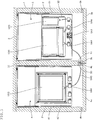
- Figs. 4 and 5 respectively show the longitudinal cross-sectional view and the transverse cross-sectional view of the cell culture apparatus 1.
- Fig. 4 shows, for the purpose of convenience, the constitution inside the thermostatic chamber 3 in an overlapped manner on the cross section taken along the center pillar 20 in the cell culture apparatus 1.
- Fig. 5 shows the first and second culture containers U20 and U30 arranged on a culture container accommodation shelf 32 in the thermostatic chamber 3 and the culture medium container U10 arranged on a culture medium container storage shelf 42 in the cold storage chamber 4.
- FIGs. 4 and 5 when the front doors 3a and 4a are closed, the packing elements 3b and 4b abut against a housing 2 and an abutting surface 2a of the center pillar 20 of the cell culture apparatus 1.
- a resin-made block 50 is embedded in the abutting surface 2a of the center pillar 20 for each culture container accommodation shelf, and is fixed by a bolt (not shown).
- a communication groove 51 having almost the same width as that of the transfer tube U40 is formed in the block 50.
- the communication groove 51 is formed so as to permit the thermostatic chamber 3 to communicate with the cold storage chamber 4, and the transfer tube U40 of the cell culture unit U is fitted into the communication groove 51. Therefore, as shown in Fig. 5 , the transfer tube U40 is not crushed by the packing elements 3b and 4b when the front doors 3a and 4a are closed, whereby communication through the transfer tube U40 between the thermostatic chamber 3 and the cold storage chamber 4 is maintained.
- thermostatic chamber 3 and the cold storage chamber 4 are kept communicated with the outside through the communication groove 51 when the transfer tube U40 is not fitted into the communication groove 51, heat and carbon dioxide gas are escaped from the thermostatic chamber 3 through the communication groove 51, and such escapes are not preferable in view of control of the temperature and air environment in the thermostatic chamber 3. Further, since external heat enters the cold storage chamber 4 through the communication groove 51, it is not preferable in view of temperature control in the cold storage chamber 4.
- the cell culture apparatus 1 of the present embodiment is provided with a shut-off mechanism 5 for blocking communication of the thermostatic chamber 3 and the cold storage chamber 4 with the outside through the communication groove 51 when the transfer tube U40 is removed from the communication groove 51.
- Fig. 6 shows a perspective view of the block 50 that constitutes the shut-off mechanism 5.
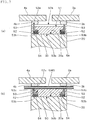
- Figs. 7 and 8 show the cross sectional views taken along the line A-A and B-B in Fig. 6 , respectively.
- Fig. 7 shows the block 50 fitted in the center pillar 20 and the front doors 3a and 4a are closed.
- An upper surface 50a of the block 50 on which the communication groove 51 is formed serves as the abutting surface 2a on which the packing elements 3b and 4b abut.
- Two guide holes 52 are formed in the block 50 so that each guide holes 52 opens on the upper surface 50a and crosses the communication groove 51.
- Each guide hole 52 is opened at a position in the abutting surface 2a where the position is covered by the packing elements 3b and 4b when the front doors 3a and 4a are closed.
- the guide hole 52 has larger depth than the communication groove 51.
- the guide hole 52 penetrates a bottom surface 50b of the block 50.
- the guide hole 52 may or may not necessarily penetrate.
- a plate-like shutter member 53 that is bent in an L-shape and a coil-like spring member 54 are inserted in the guide hole 52.
- the shutter member 53 can move between a blocking position that blocks the communication groove 51 shown in Figs. 6 , 7(a) and 8(a) and an opening position that opens the communication groove 51 shown in Figs. 7(b) and 8(b) .
- the upper part of the shutter member 53 blocks the communication groove 51 at the blocking position.
- the lower part 53b of the shutter member 53 is bent at right angle with respect to the upper part of the shutter member 53.
- the lower surface 53b of the lower part serves as a receiving part 53b receiving one end of the spring member 54.
- the other end of the spring member 54 abuts on the abutting surface 20a of a notched part of the center pillar 20.
- the spring member 54 serves as a press spring, and energizes the shutter member 53 to the blocking position.
- the upper surface 53c of the lower part of the shutter member 53 serves as an abutting part 53c abutting on the inner surface 52a of the guide hole 52 when the shutter member 53 is energized to the blocking position. Due to the abutting of the abutting part 53c on the inner surface of the guide hole 52, the shutter member 53 is prevented from flying out of the opening part of the guide hole 52, and the upper end surface 53a of the shutter member 53 is flushed with the abutting surface 2a when the shutter member 53 is positioned at the blocking position.
- the shutter member 53 is pushed down to the opening position by the tube U40.
- the spring constant of the spring member 54 is small so that the transfer tube U40 can be fitted into the communication groove 51 without receiving a large resistance and so that the transfer tube U40 fitted into the communication groove 51 is not pushed out.
- a gap is shown between the communication groove 51 and the outer periphery of the transfer tube U40.
- the gap is substantially not present, and the transfer tube U40 abuts against the upper end surface 53a of the shutter member 53, and pushes the shutter member 53 to the opening position.
- communication between the thermostatic chamber 3 and the cold storage chamber 4 can be maintained with the front doors 3a and 4a provided with the packing elements 3b and 4b being closed, and when the transfer tube U40 is not attached to the communication groove 51, the communication groove 51 can be automatically blocked by the shutter member 53.
- the present invention is not restricted to the above-mentioned embodiment, and various modifications are possible within the scope of the present invention.
- the communication groove 51 is formed between the thermostatic chamber 3 and the cold storage chamber 4.
- the cell culture apparatus of the present invention is not restricted to one having a two-chamber structure of a thermostatic chamber and a cold storage chamber, and one which is not provided with a cold storage chamber can be applied.
- a communication groove may be formed at any part of the abutting surfaces around the opening of the thermostatic chamber.
- a linear communication groove 51 is formed.
- the shape of the communication groove is not limited thereto, and a winding communication groove, or a communication groove of which the width or the depth partially changes, may be formed.
- the shutter member 53 is moved in a direction perpendicular to an abutting surface between the blocking position and the opening position.
- the shutter member may be moved in an oblique direction relative to the abutting surface or rotated.
- an explanation is made on an example in which the plate-like shutter member 53 is used.
- the shape of the shutter member is not restricted to this, and a shutter member having various shapes (e.g. cylindrical, prismatic, truncated cone, truncated pyramid, etc.) can be used.
- a coil-like spring member 54 is provided.
- a spring member is not limited thereto.
- An appropriate and preferable energizing member such as a plate spring or various elastic bodies may be used.
- the resin-made block 50 that can be processed easily, the communication groove 51 and the guide hole 52 are formed, and the shutter member 53 and the spring member 54 are incorporated into the block 50.
- the resin-made block may not necessarily be used, and a communication groove, etc. may be directly formed on the abutting surface of the center pillar or the housing, and a shutter member, etc. may be incorporated into the center pillar or the housing.
- the block may be made from resin or metal such as aluminum.
- the present invention can preferably be used in regenerative medicine, immunotherapy, production of antibody medicine, etc. in which a large amount of cells is cultured in a closed system.
Landscapes
- Health & Medical Sciences (AREA)
- Chemical & Material Sciences (AREA)
- Life Sciences & Earth Sciences (AREA)
- Engineering & Computer Science (AREA)
- Bioinformatics & Cheminformatics (AREA)
- Wood Science & Technology (AREA)
- Organic Chemistry (AREA)
- Zoology (AREA)
- Biotechnology (AREA)
- Biomedical Technology (AREA)
- Microbiology (AREA)
- Sustainable Development (AREA)
- Biochemistry (AREA)
- General Engineering & Computer Science (AREA)
- General Health & Medical Sciences (AREA)
- Genetics & Genomics (AREA)
- Clinical Laboratory Science (AREA)
- Physics & Mathematics (AREA)
- Thermal Sciences (AREA)
- Analytical Chemistry (AREA)
- Medicinal Chemistry (AREA)
- Cell Biology (AREA)
- Virology (AREA)
- Apparatus Associated With Microorganisms And Enzymes (AREA)
Abstract
Description
- The present invention relates to a cell culture apparatus, more particularly, to a cell culture apparatus capable of communicating the inside and outside of a thermostatic chamber through a tube.
- In recent years, it has been demanded to cultivate cells, tissues, etc. in an artificial environment efficiently in fields including production of pharmaceutical products, gene therapy, regenerative medicine, immunotherapy and the like.
- In such cell culture, a cell culture unit in which a culture container used for cell culture and a culture medium container for supplying a culture medium to a culture container are connected through a tube is used. Since this cell culture unit is closed, cell culture can be conducted while eliminating the risk of contamination.
- The following
Patent Document 1 discloses a cell culture apparatus in which this type of cell culture units are stored in multistage. - Patent Document 1:
WO2007/052716 - In the cell culture, since control of temperature, air environment or the like is required, a culture container of the cell culture unit is arranged in a thermostatic chamber (incubator). On the other hand, since a culture medium of the cell culture unit is required to be stored in a refrigerator, a culture medium container is arranged in a cold storage chamber. Then, a culture medium is transferred from a culture medium container to a culture container through a tube.
- The opening parts of the thermostatic chamber and the cold storage chamber of the cell culture apparatus are sealed by a door with a packing element in order to maintain the temperature or the gas concentration in the rooms. At this time, the culture container arranged in the thermostatic room and the cell culture medium container arranged in the cold storage chamber are kept connected through a tube. When the tube is caught in the door, the tube is crushed and it becomes difficult to transfer the culture medium through the tube. In order to avoid crush of the tube, a communication groove (concave portion) into which the tube can be fitted is formed on the abutting surface which can be in contact with the packing element of the door around the openings of the thermostatic chamber and the cold storage chamber.
- By forming the communication groove on the abutting surface of the partition wall, not forming a communication hole in the partition wall, between the thermostatic chamber and the cold storage chamber, the culture container and the culture medium container can be arranged in the thermostatic chamber and the cold storage chamber, respectively, while being connected by a tube.
- If such a communication groove is formed in a cell culture apparatus, the inside and outside of the thermostatic chamber and the cold storage chamber are intercommunicated when a tube is not fitted to the communication groove. In particular, in the cell culture apparatus in which cell culture units can be stored in multiple stages, communication grooves of unused stages in each of which no cell culture unit is arranged are kept intercommunicated. As a result, a carbon dioxide gas filled in the thermostatic chamber and heat are escaped from the communication groove, and such escape is not preferable from the viewpoint of the control of the temperature and the air environment of the thermostatic chamber.
- If a dummy member is attached to the communication groove in which no tube is fitted, the communication groove can be blocked. However, it is troublesome to attach dummy members to the communication grooves one by one, and there is a risk of forgetting to attach a dummy member.
- The present invention has been attained in view of the above-mentioned circumstances, and is aimed at providing a cell culture apparatus in which communication between the inside and outside of the thermostatic chamber through a tube is maintained in a state where a door with a packing element is closed, and communication of the inside and outside of the thermostatic chamber can be automatically blocked when the tube is removed.
- In order to solve the problems mentioned above, the cell culture apparatus of the present invention is a cell culture apparatus provided with a thermostatic chamber of which an opening part is opened and closed by a door with a packing element, and on an abutting surface around the opening part that abuts against the packing element when the door is closed, a communication groove into which a tube that communicates the inside and outside of the thermostatic chamber to be fitted is formed, wherein the cell culture apparatus comprises a shut-off mechanism for blocking communication between the inside and outside of the thermostatic chamber through the communication groove when the tube is removed from the communication groove.
- According to the cell culture apparatus of the present invention, by forming a communication groove into which a tube that intercommunicates the inside and outside of the thermostatic chamber at an abutting surface around the opening of the thermostatic chamber to be fitted, not only communication of the inside and outside of the thermostatic chamber through a tube can be maintained in a state where a door with a packing element is closed, and by providing a shut-off mechanism, the communication of the inside and outside the thermostatic chamber through the communication groove can be automatically blocked when the tube is removed from the communication groove.
-
-
Fig. 1 is a schematic view of an external appearance of the cell culture apparatus according to the embodiment of the present invention; -
Fig. 2 is a schematic view of an external appearance of the cell culture apparatus according to the embodiment of the present invention; -
Fig. 3 is an explanatory view showing one example of the cell culture unit stored in the cell culture apparatus according to the embodiment of the present invention; -
Fig. 4 is an explanatory cross-sectional view of the inside of the thermostatic chamber of the cell culture apparatus according to the embodiment of the present invention; -
Fig. 5 is an explanatory plan view of the cell culture unit arranged in the cell culture apparatus according to the embodiment of the present invention; -
Fig. 6 is a perspective view of a block having shut-off mechanisms in the cell culture apparatus according the embodiment of the present invention; -
Fig. 7 is a cross-sectional view taken along line A-A inFig. 6 that shows a center pillar and doors of the cell culture apparatus according to the embodiment of the present invention, in which (a) shows a blocked state and (b) shows an intercommunicated state; and -
Fig. 8 is a cross-sectional view taken along line B-B inFig. 6 , in which (a) shows a blocked state and (b) shows an intercommunicated state. - Herein below, the embodiment of the present invention will be explained with reference to the drawings.
-
Figs. 1 and2 show a schematic external view of thecell culture apparatus 1 of the present embodiment. Thecell culture apparatus 1 is provided with thethermostatic chamber 3 and thecold storage chamber 4. They are formed by partitioning the inside of thehousing 2 by acenter pillar 20 of a heat insulating wall. The opening part of each of thethermostatic chamber 3 and thecold storage chamber 4 is closed and opened independently by afront door 3a and afront door 4a. Thefront door 3a and thefront door 4a are provided with apacking element 3b and apacking element 4b, respectively. When thefront door 3a and thefront door 4a are closed, thepacking element 3b and thepacking element 4b abut against theabutting surface 2a of thecasing 2 and thecenter pillar 20, whereby thethermostatic chamber 3 and thecold storage chamber 4 are each sealed. In theabutting surface 2a of thecenter pillar 20, a resin-madeblock 50 in which a communication groove 51 that intercommunicates thethermostatic chamber 3 and thecold storage chamber 4 is fitted. - The
thermostatic chamber 3 is adjusted to have a temperature preferable for cell culture (e.g. 37°C), and is adjusted to have a gas concentration that keeps a prescribed carbon dioxide concentration (e.g. 5%). Thecold storage chamber 4 is adjusted to have a temperature preferable for storage of a culture medium (e.g. 4°C). -
Accommodation shells thermostatic chamber 3 and thecold storage chamber 4. In order to facilitate the arrangement and removal of the cell culture units U, theaccommodation shells slide rails -
Fig. 3 shows one example of the cell culture unit U stored in thecell culture apparatus 1. The cell culture unit U comprises a first culture container U20 in which cell culture is conducted at first, a second culture container U30 to which a cell suspension is transferred after the cell culture in the first culture container U20, a culture medium container U10 that supplies a culture medium to these culture containers U20 and U30, and transfer tubes U40 and U42 that connect these containers U10, U20 and U30. - Connection of the containers by the transfer tubes U40 and U42 is controlled by a blocking element U44 such as a pinch valve. The transfer tubes U40 and U42 are formed of a flexible material such as silicone rubber and a soft vinyl chloride resin.
- When cell culture is conducted in the cell culture unit U, at first, a culture medium is transferred through the transfer tube U40 by means of the pump U41 from a port U11 in the culture medium container U10 to a port U21 of the first culture container U20 into which cells have been injected (see an arrow in a broken line (1) in
Fig. 3 ). Subsequently, after cell culture in the first culture container U20, a cell suspension is transferred from the port U21 in the first cell culture container U20 to a port U32 of the second culture container U30 through the transfer tubes U40 and U42 by means of the pump U41 (see an arrow in a broken line (2) inFig. 3 ). Further, a culture medium is transferred from the port U11 in the culture medium container U10 to the port U31 of the second culture container U30 through the transfer tubes U40 and U42 by means of the pump U41 (see an arrow in a broken line (3) inFig. 3 ). - As mentioned above, the culture medium is transferred through the transfer tube U40 from the culture medium container U10 arranged in the
cold storage chamber 4 to the first and second culture containers U20 and U30 arranged in thethermostatic chamber 3. Therefore, when thefront doors cell culture apparatus 1 are closed, it is required to maintain communication through the transfer tube U40 between thethermostatic chamber 3 and thecold storage chamber 4. -
Figs. 4 and5 respectively show the longitudinal cross-sectional view and the transverse cross-sectional view of thecell culture apparatus 1.Fig. 4 shows, for the purpose of convenience, the constitution inside thethermostatic chamber 3 in an overlapped manner on the cross section taken along thecenter pillar 20 in thecell culture apparatus 1.Fig. 5 shows the first and second culture containers U20 and U30 arranged on a culturecontainer accommodation shelf 32 in thethermostatic chamber 3 and the culture medium container U10 arranged on a culture mediumcontainer storage shelf 42 in thecold storage chamber 4. - As shown in
Figs. 4 and5 , when thefront doors packing elements housing 2 and anabutting surface 2a of thecenter pillar 20 of thecell culture apparatus 1. A resin-madeblock 50 is embedded in theabutting surface 2a of thecenter pillar 20 for each culture container accommodation shelf, and is fixed by a bolt (not shown). Acommunication groove 51 having almost the same width as that of the transfer tube U40 is formed in theblock 50. - The
communication groove 51 is formed so as to permit thethermostatic chamber 3 to communicate with thecold storage chamber 4, and the transfer tube U40 of the cell culture unit U is fitted into thecommunication groove 51. Therefore, as shown inFig. 5 , the transfer tube U40 is not crushed by thepacking elements front doors thermostatic chamber 3 and thecold storage chamber 4 is maintained. - If the
thermostatic chamber 3 and thecold storage chamber 4 are kept communicated with the outside through thecommunication groove 51 when the transfer tube U40 is not fitted into thecommunication groove 51, heat and carbon dioxide gas are escaped from thethermostatic chamber 3 through thecommunication groove 51, and such escapes are not preferable in view of control of the temperature and air environment in thethermostatic chamber 3. Further, since external heat enters thecold storage chamber 4 through thecommunication groove 51, it is not preferable in view of temperature control in thecold storage chamber 4. - The
cell culture apparatus 1 of the present embodiment is provided with a shut-offmechanism 5 for blocking communication of thethermostatic chamber 3 and thecold storage chamber 4 with the outside through thecommunication groove 51 when the transfer tube U40 is removed from thecommunication groove 51. -
Fig. 6 shows a perspective view of theblock 50 that constitutes the shut-offmechanism 5.Figs. 7 and8 show the cross sectional views taken along the line A-A and B-B inFig. 6 , respectively.Fig. 7 shows theblock 50 fitted in thecenter pillar 20 and thefront doors - An
upper surface 50a of theblock 50 on which thecommunication groove 51 is formed serves as the abuttingsurface 2a on which thepacking elements block 50 so that each guide holes 52 opens on theupper surface 50a and crosses thecommunication groove 51. Eachguide hole 52 is opened at a position in theabutting surface 2a where the position is covered by thepacking elements front doors guide hole 52 has larger depth than thecommunication groove 51. In the present embodiment, theguide hole 52 penetrates abottom surface 50b of theblock 50. Theguide hole 52 may or may not necessarily penetrate. - A plate-
like shutter member 53 that is bent in an L-shape and a coil-like spring member 54 are inserted in theguide hole 52. Theshutter member 53 can move between a blocking position that blocks thecommunication groove 51 shown inFigs. 6 ,7(a) and8(a) and an opening position that opens thecommunication groove 51 shown inFigs. 7(b) and8(b) . - The upper part of the
shutter member 53 blocks thecommunication groove 51 at the blocking position. On the other hand, thelower part 53b of theshutter member 53 is bent at right angle with respect to the upper part of theshutter member 53. Thelower surface 53b of the lower part serves as a receivingpart 53b receiving one end of thespring member 54. The other end of thespring member 54 abuts on theabutting surface 20a of a notched part of thecenter pillar 20. Thespring member 54 serves as a press spring, and energizes theshutter member 53 to the blocking position. - The
upper surface 53c of the lower part of theshutter member 53 serves as anabutting part 53c abutting on theinner surface 52a of theguide hole 52 when theshutter member 53 is energized to the blocking position. Due to the abutting of theabutting part 53c on the inner surface of theguide hole 52, theshutter member 53 is prevented from flying out of the opening part of theguide hole 52, and theupper end surface 53a of theshutter member 53 is flushed with theabutting surface 2a when theshutter member 53 is positioned at the blocking position. - As shown in
Figs. 7(a) and8(a) , when the transfer tube U40 is not attached to thecommunication groove 51, theshutter member 53 energized by thespring member 54 is positioned at the blocking position. Then, as shown inFig. 7(a) , the upper end surfaces 53a of the twoshutter members 53 abut against thepacking elements front doors communication groove 51 is blocked by the twoshutter members 53, whereby thethermostatic chamber 3 and thecold storage chamber 4 are sealed. The degree of the sealing may or may not necessarily be water tight. - As shown in
Figs. 7(b) and8(b) , when the transfer tube U40 is fitted into thecommunication groove 51, theshutter member 53 is pushed down to the opening position by the tube U40. Preferably, the spring constant of thespring member 54 is small so that the transfer tube U40 can be fitted into thecommunication groove 51 without receiving a large resistance and so that the transfer tube U40 fitted into thecommunication groove 51 is not pushed out. - In
Fig. 8(b) , in order to allow the drawings to be understood easily, a gap is shown between thecommunication groove 51 and the outer periphery of the transfer tube U40. The gap is substantially not present, and the transfer tube U40 abuts against theupper end surface 53a of theshutter member 53, and pushes theshutter member 53 to the opening position. - As mentioned above, according to the cell culture apparatus of the present embodiment, communication between the
thermostatic chamber 3 and thecold storage chamber 4 can be maintained with thefront doors packing elements communication groove 51, thecommunication groove 51 can be automatically blocked by theshutter member 53. - Hereinabove, the embodiment of the present invention was explained. The present invention is not restricted to the above-mentioned embodiment, and various modifications are possible within the scope of the present invention. For example, in the above-mentioned embodiment, an example is given in which the
communication groove 51 is formed between thethermostatic chamber 3 and thecold storage chamber 4. The cell culture apparatus of the present invention is not restricted to one having a two-chamber structure of a thermostatic chamber and a cold storage chamber, and one which is not provided with a cold storage chamber can be applied. Further, a communication groove may be formed at any part of the abutting surfaces around the opening of the thermostatic chamber. - In the above-mentioned embodiment, an explanation was made on an example in which a
linear communication groove 51 is formed. In the present invention, the shape of the communication groove is not limited thereto, and a winding communication groove, or a communication groove of which the width or the depth partially changes, may be formed. - In the above-mentioned embodiment, an explanation was made on an example in which the
shutter member 53 is moved in a direction perpendicular to an abutting surface between the blocking position and the opening position. In the present invention, the shutter member may be moved in an oblique direction relative to the abutting surface or rotated. Further, in the above-mentioned embodiment, an explanation is made on an example in which the plate-like shutter member 53 is used. In the present invention, the shape of the shutter member is not restricted to this, and a shutter member having various shapes (e.g. cylindrical, prismatic, truncated cone, truncated pyramid, etc.) can be used. - In the above-mentioned embodiment, an explanation is made on an example in which a coil-
like spring member 54 is provided. In the present invention, a spring member is not limited thereto. An appropriate and preferable energizing member such as a plate spring or various elastic bodies may be used. - In the above-mentioned embodiment, an explanation was made on an example in which, in the resin-made
block 50 that can be processed easily, thecommunication groove 51 and theguide hole 52 are formed, and theshutter member 53 and thespring member 54 are incorporated into theblock 50. In the present invention, the resin-made block may not necessarily be used, and a communication groove, etc. may be directly formed on the abutting surface of the center pillar or the housing, and a shutter member, etc. may be incorporated into the center pillar or the housing. The block may be made from resin or metal such as aluminum. - The present invention can preferably be used in regenerative medicine, immunotherapy, production of antibody medicine, etc. in which a large amount of cells is cultured in a closed system.
- The documents described in the specification and the specification of the Japanese application on the basis of which the present application claims Paris convention priority are incorporated herein by reference in its entirety.
-
- 1. Cell culture apparatus
- 2. Housing
- 2a Abutting surface
- 20. Center pillar
- 3. Thermostatic chamber
- 3a. Front door
- 3b. Packing element
- 31. Slide rail
- 32. Culture container accommodation shelf
- 4. Cold storage chamber
- 4a. Front door
- 4b. Packing element
- 41. Slide rail
- 42. Culture medium container accommodation shelf
- 5. Shut-off mechanism
- 50. Block
- 50a. Abutting surface
- 50b. Bottom surface
- 51. Communication groove
- 52. Guide hole
- 53. Shutter member
- 53a. Upper end surface
- 53b. Receiving part
- 53c. abutting part
- 54. Spring member
- U. Cell culture unit
- U10. Culture medium container
- U20. First culture container
- U30. Second culture container
- U40. Transfer tube
Claims (7)
- A cell culture apparatus provided with a thermostatic chamber of which an opening part is opened and closed by a door with a packing element and being formed a communication groove, into which a tube that communicates the inside and outside of the thermostatic chamber to be fitted, in an abutting surface around the opening part that abuts against the packing element when the door is closed, comprising
a shut-off mechanism for blocking communication between the inside and outside of the thermostatic chamber through the communication groove when the tube is removed from the communication groove. - The cell culture apparatus according to claim 1, wherein the shut-off mechanism comprises:a guide hole which is opened in the abutting surface, cross the communication groove and has a larger depth than the communication groove;a shutter member which is fitted into the guide hole and is displaced between the blocking position for blocking the communication groove and an opening position for opening the communication groove, anda spring member that energizes the shutter member to the blocking position.
- The cell culture apparatus according to claim 2, wherein the guide hole is opened at a position in the abutting surface that is covered by the packing element when the door is closed.
- The cell culture apparatus according to claim 2 or 3, wherein the shutter member has an upper end surface that is flushed with the abutting surface when the shutter member is positioned on the blocking position.
- The cell culture apparatus according to any one of claims 2 to 4, wherein the shutter member has a receiving part that receives the spring member and an abutting part that abuts against an inner surface of the guide hole when the shutter member is energized to the blocking position by the spring member.
- The cell culture apparatus according to any one of claims 1 to 5, wherein the cell culture apparatus has a cold storage chamber adjacent to the thermostatic chamber, and the communication groove is formed on the abutting surface of a center pillar separating off the cold storage chamber from the thermostatic chamber.
- The cell culture apparatus according to any one of claims 2 to 6, wherein the cell culture apparatus comprises a block fitted to the abutting surface,
the communication groove and the guide hole are formed in the block, and
the shutter member and the spring member are incorporated in the block.
Applications Claiming Priority (2)
| Application Number | Priority Date | Filing Date | Title |
|---|---|---|---|
| JP2015090633A JP6008013B1 (en) | 2015-04-27 | 2015-04-27 | Cell culture equipment |
| PCT/JP2016/002061 WO2016174844A1 (en) | 2015-04-27 | 2016-04-15 | Cell culture device |
Publications (1)
| Publication Number | Publication Date |
|---|---|
| EP3290508A1 true EP3290508A1 (en) | 2018-03-07 |
Family
ID=57140169
Family Applications (1)
| Application Number | Title | Priority Date | Filing Date |
|---|---|---|---|
| EP16786123.6A Withdrawn EP3290508A1 (en) | 2015-04-27 | 2016-04-15 | Cell culture device |
Country Status (7)
| Country | Link |
|---|---|
| US (1) | US20180298321A1 (en) |
| EP (1) | EP3290508A1 (en) |
| JP (1) | JP6008013B1 (en) |
| KR (1) | KR20170110146A (en) |
| CN (1) | CN107532133A (en) |
| TW (1) | TW201704463A (en) |
| WO (1) | WO2016174844A1 (en) |
Cited By (1)
| Publication number | Priority date | Publication date | Assignee | Title |
|---|---|---|---|---|
| EP3196289A4 (en) * | 2014-09-17 | 2018-06-06 | Toyo Seikan Group Holdings, Ltd. | Liquid delivery method for cell culture system, and cell culture system |
Families Citing this family (6)
| Publication number | Priority date | Publication date | Assignee | Title |
|---|---|---|---|---|
| CN111542592A (en) * | 2017-11-08 | 2020-08-14 | 株式会社Ihi | Connection unit for cell culture apparatus, incubator apparatus, and cell culture apparatus |
| US10889792B2 (en) | 2018-02-09 | 2021-01-12 | Global Life Sciences Solutions Usa Llc | Cell expansion vessel systems and methods |
| US20210087510A1 (en) * | 2018-02-09 | 2021-03-25 | Global Life Sciences Solutions Usa Llc | Disposable kit for bioprocessing |
| CN109321430B (en) * | 2018-11-14 | 2022-04-29 | 王奕童 | Multi-environment microbial incubator |
| CN112457988B (en) * | 2020-11-19 | 2022-08-26 | 江西迈柯菲生物医药科技有限公司 | Large-scale adherence cell culture device of three-dimensional |
| CN112961761A (en) * | 2021-02-08 | 2021-06-15 | 滨州职业学院 | Medical microbiology experimental apparatus |
Family Cites Families (9)
| Publication number | Priority date | Publication date | Assignee | Title |
|---|---|---|---|---|
| ES2286750T3 (en) * | 1998-05-01 | 2007-12-01 | Gen-Probe Incorporated | DEVICE FOR SHAKING THE LIQUID CONTENT OF A CONTAINER. |
| KR20080072022A (en) * | 2005-11-01 | 2008-08-05 | 가부시키가이샤 메디넷 | Cell culture apparatus, cell culture method, cell culture program, and cell culture system |
| JP4953769B2 (en) * | 2006-11-02 | 2012-06-13 | 三洋電機株式会社 | Cell culture device and cell culture cassette |
| JP2010142196A (en) * | 2008-12-22 | 2010-07-01 | Sanyo Electric Co Ltd | Cell culture apparatus and cell culture cassette |
| JP5714316B2 (en) * | 2010-12-22 | 2015-05-07 | 株式会社日立製作所 | Cell culture equipment |
| EP2639294A1 (en) * | 2012-03-15 | 2013-09-18 | CellProthera | Automaton and automated method for cell culture |
| JP6173792B2 (en) * | 2013-06-27 | 2017-08-02 | 株式会社ミツトヨ | Thermostatic bath, linear expansion coefficient measuring device, and thermostatic bath control method |
| CN203668361U (en) * | 2013-12-10 | 2014-06-25 | 青岛润达生物科技有限公司 | Simple constant-temperature incubator |
| JP6405690B2 (en) * | 2014-05-09 | 2018-10-17 | 東洋製罐グループホールディングス株式会社 | Multi-chamber culture container and cell culture method |
-
2015
- 2015-04-27 JP JP2015090633A patent/JP6008013B1/en active Active
-
2016
- 2016-04-15 CN CN201680024020.XA patent/CN107532133A/en active Pending
- 2016-04-15 KR KR1020177025165A patent/KR20170110146A/en not_active Ceased
- 2016-04-15 EP EP16786123.6A patent/EP3290508A1/en not_active Withdrawn
- 2016-04-15 US US15/569,517 patent/US20180298321A1/en not_active Abandoned
- 2016-04-15 WO PCT/JP2016/002061 patent/WO2016174844A1/en not_active Ceased
- 2016-04-22 TW TW105112615A patent/TW201704463A/en unknown
Cited By (1)
| Publication number | Priority date | Publication date | Assignee | Title |
|---|---|---|---|---|
| EP3196289A4 (en) * | 2014-09-17 | 2018-06-06 | Toyo Seikan Group Holdings, Ltd. | Liquid delivery method for cell culture system, and cell culture system |
Also Published As
| Publication number | Publication date |
|---|---|
| CN107532133A (en) | 2018-01-02 |
| TW201704463A (en) | 2017-02-01 |
| US20180298321A1 (en) | 2018-10-18 |
| JP2016202121A (en) | 2016-12-08 |
| JP6008013B1 (en) | 2016-10-19 |
| WO2016174844A1 (en) | 2016-11-03 |
| KR20170110146A (en) | 2017-10-10 |
Similar Documents
| Publication | Publication Date | Title |
|---|---|---|
| EP3290508A1 (en) | Cell culture device | |
| WO2016042741A1 (en) | Liquid delivery method for cell culture system, and cell culture system | |
| CN103002856B (en) | Systems and methods for use in freezing, thawing and storing biopharmaceutical materials | |
| US20200087605A1 (en) | Bag assembly for cultivation of cells | |
| CN106170540B (en) | Multi-chamber culture vessel and cell culture method | |
| JP2008532539A5 (en) | ||
| RU2622749C9 (en) | Method and device for manufacturing capsules | |
| JP2008532539A (en) | Maturation and transport system of cellular entities | |
| WO2016042743A1 (en) | Cell culture apparatus | |
| RU2015143861A (en) | ADJUSTABLE UNCLASSIFIED FILLING DEVICE AND METHOD | |
| CA2894161C (en) | Platelet concentrate preservation method | |
| ES2911181T3 (en) | Medical device for the preservation of corneal tissue, including a flattening cap and optionally a trephination cap | |
| EP3243383A1 (en) | Frozen bag container | |
| JP2017512645A5 (en) | ||
| FR3061633A1 (en) | DEVICE AND METHOD FOR PRESERVING AND TRANSPORTING AT LEAST ONE HUMAN OR ANIMAL TISSUE FOR EX VIVO TRANSPLANT OR EXPERIENCE | |
| CN112437808A (en) | Disposable cartridge cooperating with a platform in a flexible system for processing and/or operating fluids | |
| ES2911631T3 (en) | Medical device in the form of a cassette for the conservation of a corneal sample | |
| EP2636729A1 (en) | Cell culture device for microwell plate and fluidics system | |
| US10493445B2 (en) | Fluidic system for processing a sample fluid | |
| ES2363338T3 (en) | EXPERIMENTATION DEVICE. | |
| US20150329816A1 (en) | Bioreactor Chamber | |
| CN116280606B (en) | Medical medicine constant temperature preservation box capable of separating multiple chambers | |
| KR20210013857A (en) | A cell culture plate | |
| US10787636B2 (en) | Non-powered constant-temperature cell transfer device | |
| KR101793508B1 (en) | A cell culture case and cell culture device comprising the cell culture case |
Legal Events
| Date | Code | Title | Description |
|---|---|---|---|
| STAA | Information on the status of an ep patent application or granted ep patent |
Free format text: STATUS: THE INTERNATIONAL PUBLICATION HAS BEEN MADE |
|
| PUAI | Public reference made under article 153(3) epc to a published international application that has entered the european phase |
Free format text: ORIGINAL CODE: 0009012 |
|
| STAA | Information on the status of an ep patent application or granted ep patent |
Free format text: STATUS: REQUEST FOR EXAMINATION WAS MADE |
|
| 17P | Request for examination filed |
Effective date: 20171026 |
|
| AK | Designated contracting states |
Kind code of ref document: A1 Designated state(s): AL AT BE BG CH CY CZ DE DK EE ES FI FR GB GR HR HU IE IS IT LI LT LU LV MC MK MT NL NO PL PT RO RS SE SI SK SM TR |
|
| AX | Request for extension of the european patent |
Extension state: BA ME |
|
| DAV | Request for validation of the european patent (deleted) | ||
| DAX | Request for extension of the european patent (deleted) | ||
| STAA | Information on the status of an ep patent application or granted ep patent |
Free format text: STATUS: THE APPLICATION HAS BEEN WITHDRAWN |
|
| 18W | Application withdrawn |
Effective date: 20180823 |