EP3290367A1 - Inner side out roll printing - Google Patents
Inner side out roll printing Download PDFInfo
- Publication number
- EP3290367A1 EP3290367A1 EP17188281.4A EP17188281A EP3290367A1 EP 3290367 A1 EP3290367 A1 EP 3290367A1 EP 17188281 A EP17188281 A EP 17188281A EP 3290367 A1 EP3290367 A1 EP 3290367A1
- Authority
- EP
- European Patent Office
- Prior art keywords
- media
- medium
- roll
- printing
- feeding unit
- Prior art date
- Legal status (The legal status is an assumption and is not a legal conclusion. Google has not performed a legal analysis and makes no representation as to the accuracy of the status listed.)
- Granted
Links
- 238000007639 printing Methods 0.000 title claims abstract description 166
- 238000003854 Surface Print Methods 0.000 claims abstract description 23
- 238000000034 method Methods 0.000 claims description 19
- 239000002609 medium Substances 0.000 description 123
- 230000032258 transport Effects 0.000 description 119
- 239000000463 material Substances 0.000 description 24
- 238000003780 insertion Methods 0.000 description 10
- 230000037431 insertion Effects 0.000 description 10
- 239000010410 layer Substances 0.000 description 6
- 238000007641 inkjet printing Methods 0.000 description 5
- 239000012530 fluid Substances 0.000 description 4
- 239000000123 paper Substances 0.000 description 4
- 239000003086 colorant Substances 0.000 description 3
- 238000012986 modification Methods 0.000 description 3
- 230000004048 modification Effects 0.000 description 3
- 239000011248 coating agent Substances 0.000 description 2
- 238000000576 coating method Methods 0.000 description 2
- 230000001419 dependent effect Effects 0.000 description 2
- 239000004816 latex Substances 0.000 description 2
- 229920000126 latex Polymers 0.000 description 2
- 239000004033 plastic Substances 0.000 description 2
- 229920003023 plastic Polymers 0.000 description 2
- 238000012545 processing Methods 0.000 description 2
- 239000004753 textile Substances 0.000 description 2
- 238000004804 winding Methods 0.000 description 2
- 238000010146 3D printing Methods 0.000 description 1
- 230000003213 activating effect Effects 0.000 description 1
- 239000000853 adhesive Substances 0.000 description 1
- 230000001070 adhesive effect Effects 0.000 description 1
- 238000003491 array Methods 0.000 description 1
- 239000011247 coating layer Substances 0.000 description 1
- 238000004891 communication Methods 0.000 description 1
- 238000013461 design Methods 0.000 description 1
- 238000001514 detection method Methods 0.000 description 1
- 238000010586 diagram Methods 0.000 description 1
- 239000012526 feed medium Substances 0.000 description 1
- 239000011888 foil Substances 0.000 description 1
- 238000004519 manufacturing process Methods 0.000 description 1
- 238000002203 pretreatment Methods 0.000 description 1
- 230000001360 synchronised effect Effects 0.000 description 1
- 230000007723 transport mechanism Effects 0.000 description 1
- 238000011282 treatment Methods 0.000 description 1
- 238000011144 upstream manufacturing Methods 0.000 description 1
- 125000000391 vinyl group Chemical group [H]C([*])=C([H])[H] 0.000 description 1
- 229920002554 vinyl polymer Polymers 0.000 description 1
- 238000009736 wetting Methods 0.000 description 1
Images


Classifications
-
- B—PERFORMING OPERATIONS; TRANSPORTING
- B65—CONVEYING; PACKING; STORING; HANDLING THIN OR FILAMENTARY MATERIAL
- B65H—HANDLING THIN OR FILAMENTARY MATERIAL, e.g. SHEETS, WEBS, CABLES
- B65H19/00—Changing the web roll
- B65H19/10—Changing the web roll in unwinding mechanisms or in connection with unwinding operations
- B65H19/12—Lifting, transporting, or inserting the web roll; Removing empty core
- B65H19/126—Lifting, transporting, or inserting the web roll; Removing empty core with both-ends supporting arrangements
-
- B—PERFORMING OPERATIONS; TRANSPORTING
- B41—PRINTING; LINING MACHINES; TYPEWRITERS; STAMPS
- B41J—TYPEWRITERS; SELECTIVE PRINTING MECHANISMS, i.e. MECHANISMS PRINTING OTHERWISE THAN FROM A FORME; CORRECTION OF TYPOGRAPHICAL ERRORS
- B41J15/00—Devices or arrangements of selective printing mechanisms, e.g. ink-jet printers or thermal printers, specially adapted for supporting or handling copy material in continuous form, e.g. webs
- B41J15/04—Supporting, feeding, or guiding devices; Mountings for web rolls or spindles
- B41J15/042—Supporting, feeding, or guiding devices; Mountings for web rolls or spindles for loading rolled-up continuous copy material into printers, e.g. for replacing a used-up paper roll; Point-of-sale printers with openable casings allowing access to the rolled-up continuous copy material
-
- B—PERFORMING OPERATIONS; TRANSPORTING
- B65—CONVEYING; PACKING; STORING; HANDLING THIN OR FILAMENTARY MATERIAL
- B65H—HANDLING THIN OR FILAMENTARY MATERIAL, e.g. SHEETS, WEBS, CABLES
- B65H2301/00—Handling processes for sheets or webs
- B65H2301/10—Selective handling processes
- B65H2301/13—Relative to size or orientation of the material
- B65H2301/132—Relative to size or orientation of the material single face or double face
- B65H2301/1321—Printed material
-
- B—PERFORMING OPERATIONS; TRANSPORTING
- B65—CONVEYING; PACKING; STORING; HANDLING THIN OR FILAMENTARY MATERIAL
- B65H—HANDLING THIN OR FILAMENTARY MATERIAL, e.g. SHEETS, WEBS, CABLES
- B65H2403/00—Power transmission; Driving means
- B65H2403/90—Machine drive
- B65H2403/94—Other features of machine drive
- B65H2403/942—Bidirectional powered handling device
-
- G—PHYSICS
- G03—PHOTOGRAPHY; CINEMATOGRAPHY; ANALOGOUS TECHNIQUES USING WAVES OTHER THAN OPTICAL WAVES; ELECTROGRAPHY; HOLOGRAPHY
- G03G—ELECTROGRAPHY; ELECTROPHOTOGRAPHY; MAGNETOGRAPHY
- G03G15/00—Apparatus for electrographic processes using a charge pattern
- G03G15/65—Apparatus which relate to the handling of copy material
- G03G15/6517—Apparatus for continuous web copy material of plain paper, e.g. supply rolls; Roll holders therefor
- G03G15/652—Feeding a copy material originating from a continuous web roll
Definitions
- the present invention generally pertains to a media input device, a printing system, as well as a method for inner side out printing of web media provided as a media roll.
- printing on the inner side of the medium may be required, if the desired side is facing inwards on the media roll.
- the media roll is repositioned on its bearing support in a 'flipped' position with respect to outer side printing.
- the medium is then guided from the media roll upwards along the turn bar to the print heads, such that the inner side of the medium faces the print heads.
- a disadvantage of the known printing system is that is requires a large amount of vacant space above the media rolls. This results in a large and bulky printing system. In compact roll printing systems, especially ones with one or more media loading trays for holding multiple rolls, such space is generally unavailable.
- the present invention provides a media input device according to claim 1, a printing system according to claim 9, and a method according to claim 12.
- a media input device for a web-based printing system comprises:
- the media input device which may be a media loading bin or tray of a printing system, is configured to hold at least two media rolls during operation.
- the media input device is provided with a first bearing support for rotatably holding the first media roll and a second bearing support for rotatably holding the second media roll.
- the first and second bearing supports are both positioned spaced apart from one another within the media input device.
- the first and second media rolls are positioned within an inner chamber of the media input device.
- first and second media feeding units have been provided at one or more edges or borders of the inner chamber.
- the first media feeding unit is positioned to receive a first medium from the first media roll, while the second media feeding unit is positioned to receive a second medium from the second media roll.
- the first and second transport paths are arranged for receiving the first and second media from their respective first and second media rolls and for transporting the first and second media from their media rolls to their respective media feeding units.
- the first and second media feeding units then feed the first and second media towards an image forming device in the printing system, such that these media may be printed on their outer sides or surfaces.
- the first and second media are fed onto the main transport path in a state or orientation suitable for printing on the outer side of said media by the print heads of the image forming unit of the printing system.
- the media input device further comprises a guide element positionable within the media input device for defining the inner surface printing transport path.
- the guide element may be secured to the media input device in the inner chamber of the media input device.
- the first web medium may then during operation extend to the guide element and from there to the second media feeding unit.
- the guide element defines or forms a curve in the inner surface printing transport path.
- the guide element may comprise a cylinder, one or more guide plates, rollers, or bars for supporting the first medium.
- a first media roll is positioned on the first bearing support in a 'flipped' state with respect to the media roll's orientation during outer side printing.
- the first medium of said media roll is then transported to the second media feeding unit via the inner surface printing transport path, which extends between the first media roll and the second media feeding unit.
- the first medium is thereby positioned on the main transport path in an orientation suitable for inner side out printing.
- the first medium on the main transport path is oriented as if flipped, i.e. rotated 180° around an axis parallel to the transport direction of the transport path, with respect to its orientation during outer side out printing.
- the guide element may, in one embodiment, direct or guide the first medium around the second media roll volume, or in another embodiment, direct the first medium through the second media roll volume.
- the guide element is removably positionable or mountable within the media input device, such that an operator may easily install or position the guide element when inner side printing is desired.
- the guide element may be easily and rapidly placed to bring the printing system in an inner side printing mode only when required.
- the second media roll volume may be occupied by a second media roll for printing, resulting in a space efficient configuration.
- the media input device comprises a guide element actuator for positioning the guide element in an operative position when a controller of the printing system detects a print job requiring inner side printing.
- Outer and inner sides are herein defined with respect to the position of said sides in a wound-up state on the media roll.
- Inner side printing includes printing on the side or surface of the medium which is (or was) facing inwards, i.e. towards a central axis or a wind-up core around which the medium is wound.
- Outer side includes the surface of the medium facing radially outwards when wound up as a media roll.
- the web media are cut after printing, which prevents a flipping of the web on the main transport path, as for example applied in duplex printing of cut sheets.
- the present invention provides a means for suitably orienting the first medium for inner side out printing in the media input device before said medium enters the main transport path.
- the media input device comprises a frame, which may be provided with a casing or housing to hold or at least partially enclose the media rolls.
- the frame defines the outer boundaries or edges of the media input device.
- the frame is dimensioned to fit the number of media rolls placeable in the media input device, such that the space not occupied by the media rolls (and optionally other relevant devices) is reduced or minimized.
- the frame or housing needs not be closed but comprises e.g. a bottom and a side edge, wall or surface, which together define the inner chamber or volume for holding the media rolls.
- the frame or housing is accessible from the top and/or front side (with respect to the printing system) for loading the media rolls into the inner chamber.
- the inner surface printing transport path extends through a second media roll volume which is occupiable by the second media roll on the second bearing support.
- the first bearing support defines a first media roll volume which is to be occupied or filled by the first media roll when a first media roll is loaded into the media input device.
- the second bearing support defines a substantially cylindrical volume to be occupied by the second media roll.
- the cylindrical first and second media roll volumes are co-axially positioned with respect to the rotation axis of the first and second bearing supports, respectively.
- a very compact loading tray or media input device is applied to minimize the overall dimensions of the printing system.
- the first and second media rolls volume are then positioned adjacent or adjoining and occupy the majority of the volume of the inner chamber of the media input device.
- the second media roll volume is left unoccupied or empty, such that the first medium from the first media roll may extend through the unoccupied second media roll volume to the second media feeding unit.
- the first medium is positioned with its inner side facing the print heads of the printing system, such that an image may be deposited on said inner side.
- the second bearing support is arranged for holding the guide element. No separate components for supporting the guide elements are then required.
- the inner surface printing transport path then extends along the second bearing support, for example between the support elements of the second bearing support for holding the ends of the media roll.
- the guide element is in the form of media roll support core, such as those generally used for winding up web media.
- the media roll support core is dimensioned to fit on the first bearing support without modification.
- the outer surface of the guide element may be treated to provide a low friction surface for improved transport of the first medium there over.
- the seconding bearing support is positioned between the first bearing support and the second media feeding unit.
- both media feeding units are positioned at a side of the frame (or a side wall of the inner chamber).
- the first and second media are transported from their media rolls to their respective media feeding units via their respective transport paths.
- the first transport path comprises an insertion device for receiving and guiding the first medium onto the first transport path.
- the insertion device is preferably tapered for easily receiving the first medium.
- the first transport path bypasses the second media roll volume.
- the first transport path extends preferably along the periphery or borders of the inner chamber of the media input device to the first media feeding unit.
- the first transport path extends along a top or bottom surface of the inner chamber of the media input device to the side wall of the inner chamber where the media feeding units are provided.
- the second media roll volume is positioned between the first bearing support and the second media feeding unit.
- the first media feeding unit and the first bearing support are thus positioned on opposite sides with respect to the second media roll volume.
- the second media roll is in use positioned closer to its second media feeding unit than the first media roll.
- the second transport path may then be significantly shorter than the first transport path.
- the second transport path may comprise a similar tapered insertion device.
- the respective insertion device, transport path and media feeding unit for each media roll form a very compact media feeding device for transporting the media from their media rolls to their respective media feeding unit and onto the main transport path.
- the media input device is thus designed to be compact by reducing the amount of unoccupied or functionless space in the device and by reducing or minimizing the length of first and second transport paths.
- the media input device comprises a bottom wall and at least one side wall. These walls are preferably formed by a bottom and a side plate mounted on respective sections of the frame.
- the frame defines the bottom wall which is arranged for supporting the bearing supports.
- the first and second media feeding devices are provided in or at the at least one side wall.
- the main transport path extends adjacent, and optionally parallel, to the at least one side wall during a printing operation.
- the first, second, and inner surface printing transport path are arranged for transporting a medium in a horizontal direction (or at an incline with respect to the horizontal plane), whereas the main transport path transport the media upwards to the printing system.
- the media input device may be provided as a media loading tray below the image forming unit, resulting in a compact printing system.
- first media feeding unit and the second media feeding unit each comprise a pair of transport rollers for engaging a medium and pushing said medium onto the main transport path of the printing system.
- the first and second media feeding unit each comprise a transport pinch, which engages a medium coming from the respective transport path.
- the first and second bearing supports comprise actuators for driving a media roll to push a medium along the respective transport path. With the aid of the transport rollers, suitable media may be fed without manual interference by an operator.
- the present invention provides a printing system comprising a media input device according to the present invention.
- the media input device is a media tray arranged for holding at least two media rolls.
- the media tray is arranged for a sliding engagement to the printing system for opening and closing the media tray. Two or more media rolls may be placed simultaneously in the media loading tray, while a plurality of media loading trays may be positioned above one another.
- the printing system may at all times hold a supply of several media rolls of similar or different media type to provide high productivity and/or high media versatility.
- the printing system further comprises a controller arranged for: in a first print mode:
- the actuator for rotating the first media roll is driven such that the first medium is advanced over the first transport path to the first media feeding unit in an orientation suitable for 'outer side out' printing.
- the second media roll may be driven in the same first rotation direction to transport the second medium from the second media roll to the print heads for printing on the outward facing side of the second medium.
- the first media roll is positioned 'flipped' in the first bearing support with respect to its position during outer side out printing in the first print mode.
- 'Flipped' here implies a half-turn (or 180°) rotation around a rotation axis perpendicular to the central axis of the media roll itself.
- the first media roll during inner side out printing is then rotated opposite to its rotation during outer side out printing.
- the rotation in the second rotation direction transports the first medium from the first media roll over the inner surface printing transport path to the second media feeding unit in such a manner that the inner side of the first medium is facing the print heads.
- the above described controller provides automatic synchronization between the rotation of the first media roll and the motion of the second media feeding unit in the second print mode. Thereby, erroneous transportation of the first medium is prevented.
- the present invention provides a method for inner side out printing of a web medium:
- the step of transporting further comprises transporting the medium from the first media roll through a second media roll volume defined as the volume occupied by the second media roll when positioned on a second bearing support of the media input device.
- the second media roll volume is positioned between the first bearing support and the second media feeding unit.
- the second media roll volume is free of the second media roll during inner side printing of the first medium.
- the first medium may extend through said second media roll volume, such that the first medium may be properly positioned for inner side out printing without increasing the size of the media input device.
- the step of transporting further comprises:
- first or normal print mode images are printed on the outer side of the media.
- the first media roll is driven in correspondence with the first media feeding unit.
- the second media feeding unit is required to operate synchronously to the rotation speed of the second media roll to prevent excess tension or tearing of the second medium.
- the first media roll and the second media feeding unit are actuated in correspondence with one another, i.e. similar and/or synchronous media speed or media transport stepping.
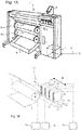
- Fig. 1A shows an image forming apparatus 1, wherein printing is achieved using a wide format inkjet printer.
- the wide-format image forming apparatus 1 comprises a housing 2, wherein the printing assembly. Any type of printing assembly may be applied within the scope of the present invention, but preferably the inkjet printing assembly shown in Fig. 1B is applied.
- the image forming apparatus 1 also comprises a storage means for storing image receiving member 3, 4, a delivery station to collect the image receiving member 3, 4 after printing and storage means 5 for marking material.
- the delivery station is embodied as a delivery tray 6, though it may further be configured as a roll winder or take-up roller for winding media onto a roll core.
- the delivery station may comprise processing means for processing the image receiving member 3, 4 after printing, e.g. a folder or a puncher.
- the wide-format image forming apparatus 1 furthermore comprises means for receiving print jobs and optionally means for manipulating print jobs. These means may include a user interface unit 8 and/or a controller 7, for example a computer.
- Images are printed on an image receiving member, for example paper, supplied by a roll 3, 4.
- the roll 3 is supported on the roll support R1, while the roll 4 is supported on the roll support R2.
- cut sheet image receiving members may be used instead of rolls 3, 4 of image receiving member.
- Printed sheets of the image receiving member, cut off from the roll 3, 4, are deposited in the delivery tray 6.
- Each one of the marking materials for use in the printing assembly are stored in four containers 5 arranged in fluid connection with the respective print heads for supplying marking material to said print heads.
- the local user interface unit 8 is integrated to the print engine and may comprise a display unit and a control panel. Alternatively, the control panel may be integrated in the display unit, for example in the form of a touch-screen control panel.
- the local user interface unit 8 is connected to a controller 7 placed inside the printing apparatus 1.
- the controller 7, for example a computer comprises a processor adapted to issue commands to the print engine, for example for controlling the print process.
- the image forming apparatus 1 may optionally be connected to a network N.
- the connection to the network N is diagrammatically shown in the form of a cable 9, but nevertheless, the connection could be wireless.
- the image forming apparatus 1 may receive printing jobs via the network. Further, optionally, the controller of the printer may be provided with a USB port, so printing jobs may be sent to the printer via this USB port.
- Fig. 1B shows an ink jet printing assembly 10.
- the ink jet printing assembly 10 comprises supporting means for supporting an image receiving member 3.
- the supporting means 11 are shown in Fig. 1B as a platen 11, but alternatively, the supporting means 11 may be a flat surface.
- the platen 11, as depicted in Fig. 1B is a rotatable drum 11, which is rotatable about its axis as indicated by arrow A.
- the supporting means 11 may be optionally provided with suction holes for holding the image receiving member 3 in a fixed position with respect to the supporting means 11.
- the ink jet printing assembly 10 comprises print heads 12a - 12d, mounted on a scanning print carriage 13.
- the scanning print carriage 13 is guided by suitable guiding means 14, 15 to move in reciprocation in the main scanning direction B.
- Each print head 12a - 12d comprises an orifice surface 16, which orifice surface 16 is provided with at least one orifice 17.
- the print heads 12a - 12d are configured to eject droplets of marking material onto the image receiving member 3.
- the platen 11, the carriage 13 and the print heads 12a - 12d are controlled by suitable controlling means 18a, 18b and 18c, respectively.
- the image receiving member 3 may be a medium in web or in sheet form and may be composed of e.g. paper, cardboard, label stock, coated paper, plastic or textile. Alternatively, the image receiving member 3 may also be an intermediate member, endless or not. Examples of endless members, which may be moved cyclically, are a belt or a drum. The image receiving member 3 is moved in the sub-scanning direction A by the platen 11 along four print heads 12a - 12d provided with a fluid marking material.
- a scanning print carriage 13 carries the four print heads 12a - 12d and may be moved in reciprocation in the main scanning direction B parallel to the platen 11, such as to enable scanning of the image receiving member 3 in the main scanning direction B. Only four print heads 12a - 12d are depicted for demonstrating the invention. In practice an arbitrary number of print heads may be employed. In any case, at least one print head 12a - 12d per color of marking material is placed on the scanning print carriage 13. For example, for a black-and-white printer, at least one print head 12a - 12d, usually containing black marking material is present. Alternatively, a black-and-white printer may comprise a white marking material, which is to be applied on a black image-receiving member 3.
- At least one print head 12a - 12d for each of the colors usually black, cyan, magenta and yellow is present.
- black marking material is used more frequently in comparison to differently colored marking material. Therefore, more print heads 12a - 12d containing black marking material may be provided on the scanning print carriage 13 compared to print heads 12a - 12d containing marking material in any of the other colors.
- the print head 12a - 12d containing black marking material may be larger than any of the print heads 12a - 12d, containing a differently colored marking material.
- the carriage 13 is guided by guiding means 14, 15.
- These guiding means 14, 15 may be rods as depicted in Fig. 1B .
- the rods may be driven by suitable driving means (not shown).
- the carriage 13 may be guided by other guiding means, such as an arm being able to move the carriage 13.
- Another alternative is to move the image receiving material 3 in the main scanning direction B.
- Each print head 12a - 12d comprises an orifice surface 16 having at least one orifice 17, in fluid communication with a pressure chamber containing fluid marking material provided in the print head 12a - 12d.
- a number of orifices 17 is arranged in a single linear array parallel to the sub-scanning direction A.
- Eight orifices 17 per print head 12a - 12d are depicted in Fig. 1B , however obviously in a practical embodiment several hundreds of orifices 17 may be provided per print head 12a - 12d, optionally arranged in multiple arrays. As depicted in Fig.
- the respective print heads 12a - 12d are placed parallel to each other such that corresponding orifices 17 of the respective print heads 12a - 12d are positioned in-line in the main scanning direction B.
- a line of image dots in the main scanning direction B may be formed by selectively activating up to four orifices 17, each of them being part of a different print head 12a - 12d.
- This parallel positioning of the print heads 12a - 12d with corresponding in-line placement of the orifices 17 is advantageous to increase productivity and/or improve print quality.
- multiple print heads 12a - 12d may be placed on the print carriage adjacent to each other such that the orifices 17 of the respective print heads 12a - 12d are positioned in a staggered configuration instead of in-line. For instance, this may be done to increase the print resolution or to enlarge the effective print area, which may be addressed in a single scan in the main scanning direction.
- the image dots are formed by ejecting droplets of marking material from the orifices 17.
- marking material Upon ejection of the marking material, some marking material may be spilled and stay on the orifice surface 16 of the print head 12a - 12d.
- the ink present on the orifice surface 16, may negatively influence the ejection of droplets and the placement of these droplets on the image receiving member 3. Therefore, it may be advantageous to remove excess of ink from the orifice surface 16.
- the excess of ink may be removed for example by wiping with a wiper and/or by application of a suitable anti-wetting property of the surface, e.g. provided by a coating.
- Fig. 2A illustrates a media input device 20 according to the present invention in a first print mode.
- the first print mode (generally the normal print mode of the printing system 1) configures the media input device 20 for printing an image on the outer side of the media M1, M2 supplied from the media rolls R1, R2.
- the media input device 20 is or comprises a media loading tray 20 for holding a plurality of media rolls R1, R2. Inside the media input device 20, at least two bearing supports 21, 22 are provided, each of which is arranged for holding a media roll R1, R2. While supported on the bearing supports 21, 22, the media rolls R1, R2 are arranged to rotate in a first rotation direction D1.
- the media input device 20 comprises a transport path P1, P2 for each bearing support 21, 22 to bring the medium M1, M2 to the main transport path MP.
- the transport paths P1, P2 are separate or individual transport paths P1, P2, defined by one or more guide elements, such as guide plates, rollers, etc.
- a media feeding unit 23, 24 is provided for transporting a medium M1, M2 from one of the transport paths P1, P2 onto the main transport path MP.
- the media M1, M2 in Fig. 2A are positioned on the main transport path MP for printing on their outer side or surface.
- the first transport path P1 from the first bearing support 21 extends below the second media roll R2 to reach the first media feeding unit 23.
- the second transport path P2, as indicated in Fig. 2A is short compared to the first transport path P1, since the second media roll R2 may be positioned on the second bearing support 22 near or adjacent the second media feeding unit 24.
- the relatively longer first transport path P1 extends along a bottom wall below the second media roll R2 to the first media feeding unit 23.
- the media feeding units 23, 24 each comprise a pair of transport rollers 23, 24 for engaging and pushing the medium M1, M2 onto and along the main transport path MP.
- the present invention is particularly advantageous when applying vulnerable materials, the print surface of which is relatively easy to damage.
- Such material may comprise a vulnerable top layer, which is preferably not contacted during the media loading process to prevent damaging or contaminating said top layer.
- Such media are preferably provided on media rolls with the top layer facing inwards for protection.
- Such media are for example known for comprising a top layer that yields a suede look and feel to the material.
- the present invention is further advantageous certain web media types wherein the two sides of the medium M1, M2 are different. The first and second sides of the medium M1, M2 are distinct and comprise different surface characteristics, generally the result of different treatment of the first side with respect to the second side.
- a self adhesive vinyl which comprises a two layer structure, wherein excess force on the printed layer is avoided to prevent damaging the material.
- an image may have already been printed on a first side or surface of the medium M1, M2, while the second side is yet to be printed.
- the two sides of the medium M1, M2 have received different pre-treatments. Only a first side of a medium M1, M2 may have been treated to optimize its surface properties for printing, e.g. by applying a coating layer on the first side. For single sided printing there is no need to apply the same coating to the second side.
- a first side may for example be optimized for printing with a first type of ink (say UV ink) while the second side is optimized for printing with a second ink type (say latex ink).
- roll printers 1 are by default configured to print on the radially outward facing side of the medium M1, M2 on the media roll R1, R2.
- the desired side of the medium M1 for printing is not always facing outwards on the media roll R1.
- the configuration in Fig. 2A cannot be applied, as the side desired for printing would be positioned facing away from the print heads 12a-d.
- Fig. 2A allows for printing on the outer side of the media roll R1 (and for roll R2 as well), but not on its inner side.
- the media input device 20 in Fig. 2A has insufficient space for providing an inversion bar or roller to 'flip' the medium M1. There is no space for such an inversion bar above the media rolls R1. This is due to the fact that the media input device 20 or loading tray 20 is designed in a compact and space efficient manner for holding a relatively large number of media rolls R1, R2 in a limited volume (see e.g. Fig. 3 ).
- one R2 of the media rolls R1, R2 may, in an optional step of the method according to the present invention, be removed, as shown in Fig. 2B .
- the second bearing support 22 is unoccupied, i.e. free of its media roll R2.
- the bearing support 22 preferably comprises a pair of support elements for rotatably supporting the ends of the media roll R2, specifically a roll core provided longitudinally through the center of the media roll R1, R2.
- a rotation actuator such as an electric motor, may be provided in the bearing support 22 to engage and rotate the media roll R2 and/or its roll core.
- the bearing support 21 may be configured in a similar manner.
- the bearing support 22 defines a tubular or cylindrical second media roll volume RV2, which is substantially the volume occupied by a media roll R2 when supported on the bearing support 22.
- the diameter of the media roll R2 varies.
- the second media volume RV2 is defined as the volume by a media roll R2 with a maximum roll diameter allowed for the media input device 20. Such a maximum roll diameter may be a device specification prescribed by the manufacturer.
- the second media roll volume RV2 may be defined as a cylindrical volume with its central axis aligned with a rotation axis of the bearing support 22.
- the second media roll volume RV2 has, for example, a radius approximately half, or less, of the distance between the first and second bearing supports 21, 22.
- the second media roll volume RV in Fig. 2B has been indicated with dashed lines.
- the second media roll volume RV2 is positioned between the first bearing support 21 and the second media feeding unit 24.
- the first media roll R1 is positioned adjacent or near the second media roll volume RV2.
- Both media feeding units 23, 24 are provided at a side wall of the media input device 20.
- the second media roll volume RV2 is positioned between the first bearing support 21 for the first media roll R1 and the media feeding units 23, 24.
- Fig. 2B further illustrates the insertion devices 25, 26 at the start of the first and second transport path P1, P2.
- the insertion devices 25, 26 are positioned adjacent their respective media rolls R1, R2 and are tapered for receiving the media M1, M2 from the media rolls R1, R2.
- the transport paths P1, P2 extend from the insertion devices 25, 26 to the media feeding units 23, 24 in the side wall of the media feeding device 20.
- the first insertion device 25 is positioned along or at the bottom wall of the media input device 20, while the second insertion device 26 is provided directly upstream of the second media feeding unit 24.
- space efficient media feeding devices comprising said respective insertion devices, transport paths, and media devices are provided.
- a first media roll R1 suited for inner side out printing is positioned on the first bearing support 21, such that it may rotated in a second rotation direction D2 for unspooling a medium M1 from the first media roll R1.
- the second rotation direction D2 is angularly opposite to the first rotation direction D1, as shown in Fig. 2A .
- the orientation of the media roll R1 in Fig. 2C may be achieved by flipping the media roll R1 180° with respect to the configuration in Figs. 2A and 2B .
- a guide element 30 is positioned in the second media roll volume RV2.
- the guide element 30 is positioned on the second bearing support 22, but may in practice positioned anywhere in between the first bearing support 21 and the second media feeding unit 24 or within the second media roll volume RV2.
- the guide element 30 defines the inner surface printing transport path IP.
- the inner surface printing transport path IP is arranged for transporting a medium M1 from the first media roll R1 on the first bearing support 21 to the second media feeding unit 24.
- the medium M1 then passes along the guide element 30, such that the inner side of the medium M1 is facing the print heads 12a-d on the main transport path MP of the printing system 1.
- the medium M1 is transported over the inner surface printing transport path IP by rotating the first roll media R1 in the second rotation direction D2 while correspondingly actuating the transport pinch of the second media feeding unit 24.
- inner side out roll printing may be easily achieved in a compact media loading tray, as shown in Fig. 2C , without increasing the dimensions of the media loading tray.
- Fig. 3 illustrates a printing system 1 according to the present invention comprising two media input devices 20 according to the present invention.
- the two media input devices 20 are positioned vertically above one another.
- the media input devices 20 are positioned in one of two loading trays.
- Each loading tray is movably connected to a fixed frame of the printing system 1, such that the loading trays may be slid in the horizontal direction for opening and closing the loading trays.
- the loading trays are designed to achieve a compact printing system 1 for holding a plurality of media rolls R1, R2. It will be appreciated that the present invention may be applied to one or more (or all) of the media input devices 20 in the printing system 1.
- each media roll R1, R2 is confined in substantially all directions during a printing operation.
- the media output device 20 comprises a frame 27 with at least a bottom wall 28 and a side 29.
- the frame 27 defines an inner chamber or volume enclosing the media rolls R1, R2. Said volume is preferably reduced or minimized to fit the first and second media rolls R1, R2.
- the bottom wall 28 supports the bearing supports 21, 22.
- the first transport path P1 extends along the bottom wall 28.
- the side wall 29 is provided with the media feeding units 23, 24, which guide the media M1, M2 through feed openings in the side wall 29 onto the main transport path MP.
- the side wall 29 and the main transport path MP extend upwards to the image forming unit 10, whereas the first, second, and inner surface printing transport paths P1, P2, IP extend parallel or at an incline to the bottom wall 28. This allows for a compact design wherein the media rolls R1, R2 may be held below the print surface 11.
- the bottom media input device 20 is configured in the manner described for Fig. 2A .
- the bottom media input device 20 allows for outer side out printing of the media M1, M2 from the media rolls R1, R2, such that the side of the medium M1, M2 facing outward on the media roll R1, R2 is facing the print heads 12a-d of the inkjet printing assembly 10 during printing.
- the top media input device 20 in Fig. 3 is configured in the manner described for Fig. 2C and facilitates inner side out printing of the medium M1 supplied from the first media roll R1.
- the side of the medium M1 facing inwards i.e. towards the rotation axis of the bearing support 21
- the side of the medium M1 facing inwards i.e. towards the rotation axis of the bearing support 21
- Fig. 3 illustrates the main media transport path MP extending substantially vertically on one side of the media input devices 20.
- a media feeding unit 23, 24 is positioned adjacent or on a side wall of the media input device 20.
- the substantially vertical side wall 29 comprises a feed opening for each media feeding unit 23, 24 to feed media M1, M2 through the side wall onto the main transport path MP.
- the media M1, M2 are brought to the media feeding units 23, 24 via the transport paths P1, P2.
- the first transport path P1 runs partially along the bottom wall 28 of the media input device 20 below the second media roll volume RV2 (or the second media roll R2 if present).
- the loading trays or media input devices 20 in Fig. 3 comprise main transport path sections, which sections during operation are aligned to form the main transport path (or part thereof).
- each of the media rolls R1, R2 is provided on a roll core C1, C2.
- the roll core is a cylinder for holding wound up web media, for example formed of cardboard or plastic.
- the guide element 30 in Fig. 3 may in an embodiment be such an empty roll core C1, C2.
- the guide element 30 may be a low friction bar or roller positionable on the second bearing support 24.
- the guide element 30 is provided on a pivoting arm, such that the guide element 30 may be pivoted from a first position outside the second media roll volume RV2 to a second position inside the second media roll volume RV2, when inner side out printing is desired.
- the controller 7 or control unit 7 of the printing system in Fig. 3 is further arranged for controlling the rotation of the media rolls R1, R2.
- the controller 7 is connected to an actuator of the first bearing support 21.
- the actuator is arranged for rotating the first media roll R1 on the first bearing support 21 in the first rotation direction D1 as well as in the second rotation direction D2.
- the controller 7 further controls the media feeding units 23, 24.
- the media feeding units in Fig. 3 each comprise a pair of transport rollers, at least one of which comprises an actuator for rotating the transport roller(s) and pushing a medium M1, M2 further onto the main transport path MP.
- the controller 7 stores on its memory first settings for a first print mode for outer side out printing and second settings for a second print mode for inner side out printing.
- controller 7 rotates the first media roll R1 on the first bearing support 21 in the first rotation direction D1.
- the first medium M1 is thereby transported from the first media roll R1 over the first transport path P1 past the second media roll volume RV2 to the first media feeding unit 23.
- the first media feeding unit 23 then engages the first medium M1 on the first transport path P1 and transports the first medium M1 to the main transport path MP.
- the first medium M1 is thereby transported to the printing assembly 10 with its outer side facing the print heads 12a-d.
- the first media roll R1 and the first media feeding unit 23 are driven in correspondence with one another, e.g. at equal speeds or stepping, to prevent damage to the first medium M1.
- controller 7 rotates the first media roll R1 on the first bearing support 21 in the second rotation direction D2, opposite to the first rotation direction D1.
- the first medium M1 is thereby transported from the first media roll R1 over the inner surface printing transport path IP through the second media roll volume RV2 to the second media feeding unit 24.
- the first medium M1 therein passes over the guide element 30 positioned on the second bearing support 22.
- the second media feeding unit 24 then engages the first medium M1 on the inner surface printing transport path IP and transports the first medium M1 to the main transport path MP.
- the first medium M1 is thereby transported to the printing assembly 10 with its inner side facing the print heads 12a-d.
- the first media roll R1 and the second media feeding unit 24 are therein actuated synchronously.
- the controller 7 is arranged to switch between the first and second print modes based on a print mode setting input through the user interface 8 by the operator.
- the controller 7 may be arranged to detect the presence of the guide element 30 on the second bearing support 22 for switching to the second print mode upon said detection.
- the second print mode is activated when selecting media specific for inner side out printing from a media catalogue stored on the controller 7.
- Fig. 4 illustrates a further embodiment of a media input device 120 according to the present invention.
- This further media input device 120 is similar to that in Figs. 2-3 , and only the differences will be discussed here.
- the inner surface printing transport path IP extends in a substantially straight line from the first media roll R1 on the first bearing support 121 through the second media roll volume RV2 to the second media feeding unit 124.
- No guide element 30 as in Fig. 2C and Fig. 3 is required.
- the first and/or second media feeding unit 124 in Fig. 4 comprises one or more guides for directing the web medium M1, M2 into the opening of the side wall to the main transport path MP.
- Fig. 4 is suited for media which cannot be fed by a pushing transport mechanism such as the transport rollers 23, 24.
- These media are for example flexible, light and/or thin media which lacks the stiffness required for pushing transport.
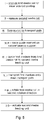
- Fig. 5 illustrates the various steps of a method according to the present invention.
- a first media roll R1 is provided on the first bearing support 21 for inside out printing (in a second print mode).
- the first media roll R1 is therein positioned flipped or inverted with respect to a media roll positioned for normal or outer side out printing (in a first print mode).
- the media roll R1 is positioned such that the media roll R1 is unspooled when it is rotated in the second rotation direction D2, which direction is opposite to the first rotation direction D1 for the first or normal print mode.
- this second media roll R2 is removed from the second bearing support 22 in step ii.
- the second media roll volume RV2 at the second bearing support 22 thereby becomes unoccupied.
- the removal step i may be performed by an operator or a media roll loading or unloading device.
- Step iii comprises forming or defining the inner surface printing transport path IP.
- the inner surface printing transport path IP is provided upon removal of the second media roll R2, allowing a medium M1 to extend from the first bearing support 121 to the second media feeding device 124.
- the inner surface printing transport path IP is formed by the step iii-a of placing the guide element 30 on the second bearing support 22.
- step iii comprises providing an unimpeded transport path IP extending from the first bearing support 21, 121 to the second media feeding unit 24, 124.
- the guide element 30 may herein be positioned by an operator or by means of an actuator for positioning the guide element 30 in the second media roll volume RV2, when the second print mode is selected.
- the first medium M1 is unspooled from the first media roll R1 and transported over the inner surface printing transport path IP.
- the first medium roll R1 is thereby controlled by the controller 7 to rotate in the second rotation direction D2.
- the first medium M1 is transported over the inner surface printing transport path IP, passing through the substantially vacant second media roll volume RV2 to the second media feeding unit 24.
- step v the first medium is transported from the second media feeding unit 24 out of the media input device 20 and onto the main transport path MP, such that the inner side of the first medium M1 is facing the print heads 12a-d during printing.
- the transport rollers of the second media feeding unit 24 then engages the first medium M1, which allows the first medium M1 to be pushed further onto the main transport path MP by the second media feeding unit 24. No further operator assistance in then required.
- Transporting the first medium M1 requires the step v-a of rotating the first media roll R1 in the second rotation direction D2.
- the controller 7 further executes the step of actuating the transport rollers of the second media feeding unit 24 to push the first medium M1 further onto the main transport path MP.
- the controller 7 controls the rotation of the first media roll R1 in correspondence with the actuation or rotation of the second media feeding unit 24 or vice versa.
- the tension in the first medium M1 may be controlled to prevent it from deforming (e.g. wrinkling) or tearing.
- the first medium M1 from the first media roll R1 may be positioned with its inner side facing the print heads 12a-d for printing on said side.
- structural elements may be generated by application of three-dimensional (3D) printing techniques. Therefore, any reference to a structural element is intended to encompass any computer executable instructions that instruct a computer to generate such a structural element by three-dimensional printing techniques or similar computer controlled manufacturing techniques. Furthermore, such a reference to a structural element encompasses a computer readable medium carrying such computer executable instructions.
- the terms and phrases used herein are not intended to be limiting; but rather, to provide an understandable description of the invention.
- the terms "a” or “an”, as used herein, are defined as one or more than one.
- the term plurality, as used herein, is defined as two or more than two.
- the term another, as used herein, is defined as at least a second or more.
- the terms including and/or having, as used herein, are defined as comprising (i.e., open language).
- the term coupled, as used herein, is defined as connected, although not necessarily directly.
Abstract
Description
- The present invention generally pertains to a media input device, a printing system, as well as a method for inner side out printing of web media provided as a media roll.
- In the graphic arts industry it is known to apply doubled sided printing to certain web media, for example two-sided banners or posters. These web media are provided as wound up media rolls and unspooled into a printing system for printing. Generally, the printing system is configured for printing on the outer surface of the medium on the media roll. Certain situations however may require printing on the inner side of the medium on the media roll. One example is wherein one side of the medium has already been printed on and this printed side is facing outwards. Another example is where the sides of the medium have been treated for different ink types. One side may require e.g.UV printing on a first printer, while the other side has been optimized for e.g. latex printing on a second printer. In such cases, printing on the inner side of the medium may be required, if the desired side is facing inwards on the media roll. It is known, for example from US patent application
US2013/0277482 A1 , to provide a printing system with an turn bar or roller above the media roll to 'flip' the medium when inner side printing is desired. For inner side printing, the media roll is repositioned on its bearing support in a 'flipped' position with respect to outer side printing. The medium is then guided from the media roll upwards along the turn bar to the print heads, such that the inner side of the medium faces the print heads. A disadvantage of the known printing system is that is requires a large amount of vacant space above the media rolls. This results in a large and bulky printing system. In compact roll printing systems, especially ones with one or more media loading trays for holding multiple rolls, such space is generally unavailable. - It is on object of the present invention to provide a compact media input device for holding multiple media rolls and for printing on the inner side of a web medium without increasing the overall dimensions of the media input device.
- Thereto, the present invention provides a media input device according to
claim 1, a printing system according toclaim 9, and a method according to claim 12. - In a first aspect of the present invention, a media input device for a web-based printing system is provided. The media input device comprises:
- a first bearing support for rotatably supporting a first media roll;
- a first media feeding unit for transporting a first medium from the first media roll to a main transport path of the printing system;
- a first transport path extending inside the media input device from the first bearing support to the first media feeding unit to position the first medium supplied from the first media roll for printing on an outer surface of the first medium;
- a second bearing support for rotatably supporting a second media roll;
- a second media feeding unit for transporting a second medium from the second media roll to a main transport path of the printing system;
- a second transport path extending inside the media input device from the second bearing support to the second media feeding unit to position the second medium supplied from the second media roll for printing on an outer surface of the second medium; and
- an inner surface printing transport path extending from the first bearing support to the second media feeding unit to position the first medium supplied from the first media roll for printing on an inner surface of the first medium.
- The media input device, which may be a media loading bin or tray of a printing system, is configured to hold at least two media rolls during operation. Thereto, the media input device is provided with a first bearing support for rotatably holding the first media roll and a second bearing support for rotatably holding the second media roll. The first and second bearing supports are both positioned spaced apart from one another within the media input device. During use, the first and second media rolls are positioned within an inner chamber of the media input device. To guide the media out of the inner chamber first and second media feeding units have been provided at one or more edges or borders of the inner chamber. The first media feeding unit is positioned to receive a first medium from the first media roll, while the second media feeding unit is positioned to receive a second medium from the second media roll. The first and second transport paths are arranged for receiving the first and second media from their respective first and second media rolls and for transporting the first and second media from their media rolls to their respective media feeding units. The first and second media feeding units then feed the first and second media towards an image forming device in the printing system, such that these media may be printed on their outer sides or surfaces. The first and second media are fed onto the main transport path in a state or orientation suitable for printing on the outer side of said media by the print heads of the image forming unit of the printing system.
- The media input device according to the present invention further comprises a guide element positionable within the media input device for defining the inner surface printing transport path. The guide element may be secured to the media input device in the inner chamber of the media input device. The first web medium may then during operation extend to the guide element and from there to the second media feeding unit. The guide element defines or forms a curve in the inner surface printing transport path. The guide element may comprise a cylinder, one or more guide plates, rollers, or bars for supporting the first medium.
- For inner side printing, a first media roll is positioned on the first bearing support in a 'flipped' state with respect to the media roll's orientation during outer side printing. The first medium of said media roll is then transported to the second media feeding unit via the inner surface printing transport path, which extends between the first media roll and the second media feeding unit. The first medium is thereby positioned on the main transport path in an orientation suitable for inner side out printing. The first medium on the main transport path is oriented as if flipped, i.e. rotated 180° around an axis parallel to the transport direction of the transport path, with respect to its orientation during outer side out printing. As such, inner side roll printing may be achieved without increasing the dimensions of the media input device. Thereby the object of the present invention has been achieved.
- More specific optional features of the invention are indicated in the dependent claims.
- The guide element may, in one embodiment, direct or guide the first medium around the second media roll volume, or in another embodiment, direct the first medium through the second media roll volume. Preferably, the guide element is removably positionable or mountable within the media input device, such that an operator may easily install or position the guide element when inner side printing is desired. As the majority of print jobs generally requires outer side printing, the guide element may be easily and rapidly placed to bring the printing system in an inner side printing mode only when required. In absence of the guide element, the second media roll volume may be occupied by a second media roll for printing, resulting in a space efficient configuration. In another embodiment, the media input device comprises a guide element actuator for positioning the guide element in an operative position when a controller of the printing system detects a print job requiring inner side printing.
- Outer and inner sides are herein defined with respect to the position of said sides in a wound-up state on the media roll. Inner side printing includes printing on the side or surface of the medium which is (or was) facing inwards, i.e. towards a central axis or a wind-up core around which the medium is wound. Outer side includes the surface of the medium facing radially outwards when wound up as a media roll. Generally the web media are cut after printing, which prevents a flipping of the web on the main transport path, as for example applied in duplex printing of cut sheets. The present invention provides a means for suitably orienting the first medium for inner side out printing in the media input device before said medium enters the main transport path.
- In an embodiment, the media input device comprises a frame, which may be provided with a casing or housing to hold or at least partially enclose the media rolls. The frame defines the outer boundaries or edges of the media input device. Preferably, the frame is dimensioned to fit the number of media rolls placeable in the media input device, such that the space not occupied by the media rolls (and optionally other relevant devices) is reduced or minimized. The frame or housing needs not be closed but comprises e.g. a bottom and a side edge, wall or surface, which together define the inner chamber or volume for holding the media rolls. Preferably, the frame or housing is accessible from the top and/or front side (with respect to the printing system) for loading the media rolls into the inner chamber.
- In an embodiment, the inner surface printing transport path extends through a second media roll volume which is occupiable by the second media roll on the second bearing support. The first bearing support defines a first media roll volume which is to be occupied or filled by the first media roll when a first media roll is loaded into the media input device. Similarly, the second bearing support defines a substantially cylindrical volume to be occupied by the second media roll. The cylindrical first and second media roll volumes are co-axially positioned with respect to the rotation axis of the first and second bearing supports, respectively. Preferably, a very compact loading tray or media input device is applied to minimize the overall dimensions of the printing system. The first and second media rolls volume are then positioned adjacent or adjoining and occupy the majority of the volume of the inner chamber of the media input device. For inner side out printing of the first medium, the second media roll volume is left unoccupied or empty, such that the first medium from the first media roll may extend through the unoccupied second media roll volume to the second media feeding unit. In this manner the first medium is positioned with its inner side facing the print heads of the printing system, such that an image may be deposited on said inner side. By providing a compact loading tray, it is possible to provide multiple of such loading trays above one another. By holding a plurality of media rolls the productivity may be increased as changing between media rolls may be performed by simply selecting another media roll or another loading tray. Multiple media rolls may be used to provide media versatility (e.g. different media types for e.g. banners, textile, paper, foil, etc.) without the need for exchanging or loading each media type into the loading tray prior to each print job. A media roll may be replenished or replaced while printing from another media roll to increase productivity.
- In a preferred embodiment, the second bearing support is arranged for holding the guide element. No separate components for supporting the guide elements are then required. The inner surface printing transport path then extends along the second bearing support, for example between the support elements of the second bearing support for holding the ends of the media roll. In an advantageous embodiment, the guide element is in the form of media roll support core, such as those generally used for winding up web media. The media roll support core is dimensioned to fit on the first bearing support without modification. The outer surface of the guide element may be treated to provide a low friction surface for improved transport of the first medium there over.
- In a further embodiment, the seconding bearing support is positioned between the first bearing support and the second media feeding unit. Preferably, both media feeding units are positioned at a side of the frame (or a side wall of the inner chamber). The first and second media are transported from their media rolls to their respective media feeding units via their respective transport paths. The first transport path comprises an insertion device for receiving and guiding the first medium onto the first transport path.
- The insertion device is preferably tapered for easily receiving the first medium. The first transport path bypasses the second media roll volume. The first transport path extends preferably along the periphery or borders of the inner chamber of the media input device to the first media feeding unit. In a preferred embodiment, the first transport path extends along a top or bottom surface of the inner chamber of the media input device to the side wall of the inner chamber where the media feeding units are provided. As such, the second media roll volume is positioned between the first bearing support and the second media feeding unit. The first media feeding unit and the first bearing support are thus positioned on opposite sides with respect to the second media roll volume. The second media roll is in use positioned closer to its second media feeding unit than the first media roll. The second transport path may then be significantly shorter than the first transport path. The second transport path may comprise a similar tapered insertion device. The respective insertion device, transport path and media feeding unit for each media roll form a very compact media feeding device for transporting the media from their media rolls to their respective media feeding unit and onto the main transport path. The media input device is thus designed to be compact by reducing the amount of unoccupied or functionless space in the device and by reducing or minimizing the length of first and second transport paths.
- In another embodiment, the media input device comprises a bottom wall and at least one side wall. These walls are preferably formed by a bottom and a side plate mounted on respective sections of the frame. The frame defines the bottom wall which is arranged for supporting the bearing supports. The first and second media feeding devices are provided in or at the at least one side wall. Preferably, the main transport path extends adjacent, and optionally parallel, to the at least one side wall during a printing operation. In a preferred embodiment, the first, second, and inner surface printing transport path are arranged for transporting a medium in a horizontal direction (or at an incline with respect to the horizontal plane), whereas the main transport path transport the media upwards to the printing system. As such, the media input device may be provided as a media loading tray below the image forming unit, resulting in a compact printing system.
- In another embodiment, the first media feeding unit and the second media feeding unit each comprise a pair of transport rollers for engaging a medium and pushing said medium onto the main transport path of the printing system. The first and second media feeding unit each comprise a transport pinch, which engages a medium coming from the respective transport path. The first and second bearing supports comprise actuators for driving a media roll to push a medium along the respective transport path. With the aid of the transport rollers, suitable media may be fed without manual interference by an operator.
- In a further aspect, the present invention provides a printing system comprising a media input device according to the present invention. Preferably, the media input device is a media tray arranged for holding at least two media rolls. The media tray is arranged for a sliding engagement to the printing system for opening and closing the media tray. Two or more media rolls may be placed simultaneously in the media loading tray, while a plurality of media loading trays may be positioned above one another. As such, the printing system may at all times hold a supply of several media rolls of similar or different media type to provide high productivity and/or high media versatility.
- In a further embodiment, the printing system further comprises a controller arranged for: in a first print mode:
- rotating the first media roll in a first rotation direction to transport the first medium from the first media roll to the first media feeding unit;
- actuating the first media feeding unit to transport the first medium from the first media roll to the main transport path of the printing system.
- rotating the first media roll in a second rotation direction opposite to the first rotation direction to transport the first medium from the first media roll to the second media feeding unit; and
- actuating the second media feeding unit to transport the first medium from the first media roll to the main transport path of the printing system.
- When printing in the first print mode (or outer side print mode), the actuator for rotating the first media roll is driven such that the first medium is advanced over the first transport path to the first media feeding unit in an orientation suitable for 'outer side out' printing. Similarly, the second media roll may be driven in the same first rotation direction to transport the second medium from the second media roll to the print heads for printing on the outward facing side of the second medium. For inner side out printing in the second print mode, the first media roll is positioned 'flipped' in the first bearing support with respect to its position during outer side out printing in the first print mode.
- 'Flipped' here implies a half-turn (or 180°) rotation around a rotation axis perpendicular to the central axis of the media roll itself. The first media roll during inner side out printing is then rotated opposite to its rotation during outer side out printing. The rotation in the second rotation direction transports the first medium from the first media roll over the inner surface printing transport path to the second media feeding unit in such a manner that the inner side of the first medium is facing the print heads. The above described controller provides automatic synchronization between the rotation of the first media roll and the motion of the second media feeding unit in the second print mode. Thereby, erroneous transportation of the first medium is prevented.
- In a further aspect, the present invention provides a method for inner side out printing of a web medium:
- a first bearing support (21, 121) for rotatably supporting a first media roll (R1);
- a first media feeding unit (23, 123) for transporting a first medium (M1) from the first media roll (R1) to a main transport path (MP) of the printing system (1);
- a first transport path (P1) extending inside the media input device (20, 120) from the first bearing support (21, 121) to the first media feeding unit (23, 123) to position the first medium (M1) supplied from the first media roll (R1) for printing on an outer surface of the first medium (M1);
- a second bearing support (22) for rotatably supporting a second media roll (R2);
- a second media feeding (24, 124) unit for transporting a second medium (M2) from the second media roll (R2) to a main transport path (MP) of the printing system (1); and
- a second transport path (P2) extending inside the media input device (20, 120) from the second bearing support (22) to the second media feeding unit (24, 124) to position the second medium (M2) supplied from the second media roll (R2) for printing on an outer surface of the second medium (M2), characterized by the method comprising the step of:
- transporting a first medium from the first media roll to the second media feeding unit, such that the first medium is oriented for printing on the inner side of the first medium. Thereby, the first medium may be effectively 'flipped' within the volume of the media input device into an orientation suitable for printing on its inner side. The object of the present invention has thus been achieved.
- In an embodiment, the step of transporting further comprises transporting the medium from the first media roll through a second media roll volume defined as the volume occupied by the second media roll when positioned on a second bearing support of the media input device. The second media roll volume is positioned between the first bearing support and the second media feeding unit. The second media roll volume is free of the second media roll during inner side printing of the first medium. Hence, the first medium may extend through said second media roll volume, such that the first medium may be properly positioned for inner side out printing without increasing the size of the media input device.
- In a further embodiment, the step of transporting further comprises:
- rotating the first media roll to transport a first medium from the first media roll to the second media feeding device;
- actuating the second media feeding device to transport the first medium from the first media roll to the main transport path of the printing system.
- In a first or normal print mode, images are printed on the outer side of the media. Thereto, the first media roll is driven in correspondence with the first media feeding unit. Likewise, for outer side printing of the second medium, the second media feeding unit is required to operate synchronously to the rotation speed of the second media roll to prevent excess tension or tearing of the second medium. For inner side printing of the first medium, the first media roll and the second media feeding unit are actuated in correspondence with one another, i.e. similar and/or synchronous media speed or media transport stepping.
- In another embodiment:
- the step of rotating the first media roll comprises rotating the first media roll in a second rotation direction, which second rotation direction is opposite to a first rotation direction for transporting a medium from the first media roll to the first media feeding unit. The first media roll while inner side printing is flipped, i.e. rotated a half turn, with respect to its orientation during outer side printing of the first medium. Unspooling the first medium then requires driving the media roll in a rotation direction opposite to the rotation direction during outer side printing.
- Further scope of applicability of the present invention will become apparent from the detailed description given hereinafter. However, it should be understood that the detailed description and specific examples, while indicating embodiments of the invention, are given by way of illustration only, since various changes and modifications within the scope of the invention will become apparent to those skilled in the art from this detailed description.
- The present invention will become more fully understood from the detailed description given hereinbelow and the accompanying schematical drawings which are given by way of illustration only, and thus are not limitative of the present invention, and wherein:
-
Fig. 1A is a schematic perspective view of a printing system according to the present invention; -
Fig. 1B is a schematic perspective view of a printing assembly of the printing system inFig. 1A ; -
Fig. 2A-C is schematic cross-sectional view of a media input device according to the present invention in a first print mode (Fig. 2A ) for outer side out printing, comprising a single media roll (Fig. 2B ), and in a second print mode (Fig. 2C ) for inner side out printing; -
Fig. 3 is a schematic cross-sectional view of a printing system according to the present invention; -
Fig. 4 is a schematic cross-sectional view of a further embodiment of a media input device according to the present invention; and -
Fig. 5 is a diagram illustrating the step of an embodiment of a method for inner side out printing according to the present invention. - The present invention will now be described with reference to the accompanying drawings, wherein the same reference numerals have been used to identify the same or similar elements throughout the several views.
-
Fig. 1A shows animage forming apparatus 1, wherein printing is achieved using a wide format inkjet printer. The wide-formatimage forming apparatus 1 comprises a housing 2, wherein the printing assembly. Any type of printing assembly may be applied within the scope of the present invention, but preferably the inkjet printing assembly shown inFig. 1B is applied. Theimage forming apparatus 1 also comprises a storage means for storingimage receiving member image receiving member Fig. 1A , the delivery station is embodied as adelivery tray 6, though it may further be configured as a roll winder or take-up roller for winding media onto a roll core. Optionally, the delivery station may comprise processing means for processing theimage receiving member image forming apparatus 1 furthermore comprises means for receiving print jobs and optionally means for manipulating print jobs. These means may include a user interface unit 8 and/or acontroller 7, for example a computer. - Images are printed on an image receiving member, for example paper, supplied by a
roll roll 3 is supported on the roll support R1, while theroll 4 is supported on the roll support R2. Alternatively, cut sheet image receiving members may be used instead ofrolls roll delivery tray 6. - Each one of the marking materials for use in the printing assembly are stored in four containers 5 arranged in fluid connection with the respective print heads for supplying marking material to said print heads.
- The local user interface unit 8 is integrated to the print engine and may comprise a display unit and a control panel. Alternatively, the control panel may be integrated in the display unit, for example in the form of a touch-screen control panel. The local user interface unit 8 is connected to a
controller 7 placed inside theprinting apparatus 1. Thecontroller 7, for example a computer, comprises a processor adapted to issue commands to the print engine, for example for controlling the print process. Theimage forming apparatus 1 may optionally be connected to a network N. The connection to the network N is diagrammatically shown in the form of acable 9, but nevertheless, the connection could be wireless. Theimage forming apparatus 1 may receive printing jobs via the network. Further, optionally, the controller of the printer may be provided with a USB port, so printing jobs may be sent to the printer via this USB port. -
Fig. 1B shows an inkjet printing assembly 10. The inkjet printing assembly 10 comprises supporting means for supporting animage receiving member 3. The supporting means 11 are shown inFig. 1B as aplaten 11, but alternatively, the supportingmeans 11 may be a flat surface. Theplaten 11, as depicted inFig. 1B , is arotatable drum 11, which is rotatable about its axis as indicated by arrow A. The supporting means 11 may be optionally provided with suction holes for holding theimage receiving member 3 in a fixed position with respect to the supportingmeans 11. The inkjet printing assembly 10 comprises print heads 12a - 12d, mounted on a scanning print carriage 13. The scanning print carriage 13 is guided by suitable guiding means 14, 15 to move in reciprocation in the main scanning direction B. Each print head 12a - 12d comprises an orifice surface 16, which orifice surface 16 is provided with at least oneorifice 17. The print heads 12a - 12d are configured to eject droplets of marking material onto theimage receiving member 3. Theplaten 11, the carriage 13 and the print heads 12a - 12d are controlled by suitable controlling means 18a, 18b and 18c, respectively. - The
image receiving member 3 may be a medium in web or in sheet form and may be composed of e.g. paper, cardboard, label stock, coated paper, plastic or textile. Alternatively, theimage receiving member 3 may also be an intermediate member, endless or not. Examples of endless members, which may be moved cyclically, are a belt or a drum. Theimage receiving member 3 is moved in the sub-scanning direction A by theplaten 11 along four print heads 12a - 12d provided with a fluid marking material. - A scanning print carriage 13 carries the four print heads 12a - 12d and may be moved in reciprocation in the main scanning direction B parallel to the
platen 11, such as to enable scanning of theimage receiving member 3 in the main scanning direction B. Only four print heads 12a - 12d are depicted for demonstrating the invention. In practice an arbitrary number of print heads may be employed. In any case, at least one print head 12a - 12d per color of marking material is placed on the scanning print carriage 13. For example, for a black-and-white printer, at least one print head 12a - 12d, usually containing black marking material is present. Alternatively, a black-and-white printer may comprise a white marking material, which is to be applied on a black image-receivingmember 3. For a full-color printer, containing multiple colors, at least one print head 12a - 12d for each of the colors, usually black, cyan, magenta and yellow is present. Often, in a full-color printer, black marking material is used more frequently in comparison to differently colored marking material. Therefore, more print heads 12a - 12d containing black marking material may be provided on the scanning print carriage 13 compared to print heads 12a - 12d containing marking material in any of the other colors. Alternatively, the print head 12a - 12d containing black marking material may be larger than any of the print heads 12a - 12d, containing a differently colored marking material. - The carriage 13 is guided by guiding
means Fig. 1B . The rods may be driven by suitable driving means (not shown). Alternatively, the carriage 13 may be guided by other guiding means, such as an arm being able to move the carriage 13. Another alternative is to move theimage receiving material 3 in the main scanning direction B. - Each print head 12a - 12d comprises an orifice surface 16 having at least one
orifice 17, in fluid communication with a pressure chamber containing fluid marking material provided in the print head 12a - 12d. On the orifice surface 16, a number oforifices 17 is arranged in a single linear array parallel to the sub-scanning direction A. Eightorifices 17 per print head 12a - 12d are depicted inFig. 1B , however obviously in a practical embodiment several hundreds oforifices 17 may be provided per print head 12a - 12d, optionally arranged in multiple arrays. As depicted inFig. 1B , the respective print heads 12a - 12d are placed parallel to each other such thatcorresponding orifices 17 of the respective print heads 12a - 12d are positioned in-line in the main scanning direction B. This means that a line of image dots in the main scanning direction B may be formed by selectively activating up to fourorifices 17, each of them being part of a different print head 12a - 12d. This parallel positioning of the print heads 12a - 12d with corresponding in-line placement of theorifices 17 is advantageous to increase productivity and/or improve print quality. Alternatively multiple print heads 12a - 12d may be placed on the print carriage adjacent to each other such that theorifices 17 of the respective print heads 12a - 12d are positioned in a staggered configuration instead of in-line. For instance, this may be done to increase the print resolution or to enlarge the effective print area, which may be addressed in a single scan in the main scanning direction. The image dots are formed by ejecting droplets of marking material from theorifices 17. - Upon ejection of the marking material, some marking material may be spilled and stay on the orifice surface 16 of the print head 12a - 12d. The ink present on the orifice surface 16, may negatively influence the ejection of droplets and the placement of these droplets on the
image receiving member 3. Therefore, it may be advantageous to remove excess of ink from the orifice surface 16. The excess of ink may be removed for example by wiping with a wiper and/or by application of a suitable anti-wetting property of the surface, e.g. provided by a coating. -
Fig. 2A illustrates amedia input device 20 according to the present invention in a first print mode. The first print mode (generally the normal print mode of the printing system 1) configures themedia input device 20 for printing an image on the outer side of the media M1, M2 supplied from the media rolls R1, R2. Themedia input device 20 is or comprises amedia loading tray 20 for holding a plurality of media rolls R1, R2. Inside themedia input device 20, at least two bearing supports 21, 22 are provided, each of which is arranged for holding a media roll R1, R2. While supported on the bearing supports 21, 22, the media rolls R1, R2 are arranged to rotate in a first rotation direction D1. By rotating the media rolls R1, R2 in said rotation direction D1, web media M1, M2 are unspooled from the media rolls R1, R2 towards a main transport path MP of theprinting system 1. Themedia input device 20 comprises a transport path P1, P2 for each bearingsupport Fig. 2A , the transport paths P1, P2 are separate or individual transport paths P1, P2, defined by one or more guide elements, such as guide plates, rollers, etc. At the end of each transport path P1, P2 amedia feeding unit - The media M1, M2 in
Fig. 2A are positioned on the main transport path MP for printing on their outer side or surface. The first transport path P1 from thefirst bearing support 21 extends below the second media roll R2 to reach the firstmedia feeding unit 23. The second transport path P2, as indicated inFig. 2A , is short compared to the first transport path P1, since the second media roll R2 may be positioned on thesecond bearing support 22 near or adjacent the secondmedia feeding unit 24. The relatively longer first transport path P1 extends along a bottom wall below the second media roll R2 to the firstmedia feeding unit 23. InFig. 2A , themedia feeding units transport rollers Fig. 2 , the outer side (or outward facing side) of the medium M1, M2 on a media roll R1, R2 is faced towards the print heads 12a-d for printing an image on said outer side. - The present invention is particularly advantageous when applying vulnerable materials, the print surface of which is relatively easy to damage. Such material may comprise a vulnerable top layer, which is preferably not contacted during the media loading process to prevent damaging or contaminating said top layer. Such media are preferably provided on media rolls with the top layer facing inwards for protection. Such media are for example known for comprising a top layer that yields a suede look and feel to the material. The present invention is further advantageous certain web media types wherein the two sides of the medium M1, M2 are different. The first and second sides of the medium M1, M2 are distinct and comprise different surface characteristics, generally the result of different treatment of the first side with respect to the second side. One example of such materials is a self adhesive vinyl, which comprises a two layer structure, wherein excess force on the printed layer is avoided to prevent damaging the material. In another example, in case of double sided printing, an image may have already been printed on a first side or surface of the medium M1, M2, while the second side is yet to be printed. In another example, the two sides of the medium M1, M2 have received different pre-treatments. Only a first side of a medium M1, M2 may have been treated to optimize its surface properties for printing, e.g. by applying a coating layer on the first side. For single sided printing there is no need to apply the same coating to the second side. In a further example, a first side may for example be optimized for printing with a first type of ink (say UV ink) while the second side is optimized for printing with a second ink type (say latex ink). Generally,
roll printers 1 are by default configured to print on the radially outward facing side of the medium M1, M2 on the media roll R1, R2. - The desired side of the medium M1 for printing is not always facing outwards on the media roll R1. In that case, the configuration in
Fig. 2A cannot be applied, as the side desired for printing would be positioned facing away from the print heads 12a-d.Fig. 2A allows for printing on the outer side of the media roll R1 (and for roll R2 as well), but not on its inner side. Themedia input device 20 inFig. 2A has insufficient space for providing an inversion bar or roller to 'flip' the medium M1. There is no space for such an inversion bar above the media rolls R1. This is due to the fact that themedia input device 20 orloading tray 20 is designed in a compact and space efficient manner for holding a relatively large number of media rolls R1, R2 in a limited volume (see e.g.Fig. 3 ). - In order to allow achieve inner side printing, wherein the desired side of the medium M1 is facing inward on the media roll R1, one R2 of the media rolls R1, R2 may, in an optional step of the method according to the present invention, be removed, as shown in
Fig. 2B . InFig. 2B , thesecond bearing support 22 is unoccupied, i.e. free of its media roll R2. The bearingsupport 22 preferably comprises a pair of support elements for rotatably supporting the ends of the media roll R2, specifically a roll core provided longitudinally through the center of the media roll R1, R2. A rotation actuator, such as an electric motor, may be provided in thebearing support 22 to engage and rotate the media roll R2 and/or its roll core. The bearingsupport 21 may be configured in a similar manner. - The bearing
support 22 defines a tubular or cylindrical second media roll volume RV2, which is substantially the volume occupied by a media roll R2 when supported on the bearingsupport 22. In practice, the diameter of the media roll R2 varies. It is preferred the second media volume RV2 is defined as the volume by a media roll R2 with a maximum roll diameter allowed for themedia input device 20. Such a maximum roll diameter may be a device specification prescribed by the manufacturer. Alternatively, the second media roll volume RV2 may be defined as a cylindrical volume with its central axis aligned with a rotation axis of the bearingsupport 22. The second media roll volume RV2 has, for example, a radius approximately half, or less, of the distance between the first and second bearing supports 21, 22. For the sake of illustration, the second media roll volume RV inFig. 2B has been indicated with dashed lines. InFig. 2B , the second media roll volume RV2 is positioned between thefirst bearing support 21 and the secondmedia feeding unit 24. The first media roll R1 is positioned adjacent or near the second media roll volume RV2. Bothmedia feeding units media input device 20. The second media roll volume RV2 is positioned between thefirst bearing support 21 for the first media roll R1 and themedia feeding units -
Fig. 2B further illustrates theinsertion devices insertion devices insertion devices media feeding units media feeding device 20. Thefirst insertion device 25 is positioned along or at the bottom wall of themedia input device 20, while thesecond insertion device 26 is provided directly upstream of the secondmedia feeding unit 24. As such space efficient media feeding devices comprising said respective insertion devices, transport paths, and media devices are provided. - In a further step of the method, a first media roll R1 suited for inner side out printing is positioned on the
first bearing support 21, such that it may rotated in a second rotation direction D2 for unspooling a medium M1 from the first media roll R1. The second rotation direction D2 is angularly opposite to the first rotation direction D1, as shown inFig. 2A . The orientation of the media roll R1 inFig. 2C may be achieved by flipping the media roll R1 180° with respect to the configuration inFigs. 2A and 2B . - In another preferred step of the method according to the present invention a
guide element 30 is positioned in the second media roll volume RV2. Preferably, theguide element 30 is positioned on thesecond bearing support 22, but may in practice positioned anywhere in between thefirst bearing support 21 and the secondmedia feeding unit 24 or within the second media roll volume RV2. Theguide element 30 defines the inner surface printing transport path IP. The inner surface printing transport path IP is arranged for transporting a medium M1 from the first media roll R1 on thefirst bearing support 21 to the secondmedia feeding unit 24. The medium M1 then passes along theguide element 30, such that the inner side of the medium M1 is facing the print heads 12a-d on the main transport path MP of theprinting system 1. During operation, the medium M1 is transported over the inner surface printing transport path IP by rotating the first roll media R1 in the second rotation direction D2 while correspondingly actuating the transport pinch of the secondmedia feeding unit 24. In this manner inner side out roll printing may be easily achieved in a compact media loading tray, as shown inFig. 2C , without increasing the dimensions of the media loading tray. -
Fig. 3 illustrates aprinting system 1 according to the present invention comprising twomedia input devices 20 according to the present invention. The twomedia input devices 20 are positioned vertically above one another. Themedia input devices 20 are positioned in one of two loading trays. Each loading tray is movably connected to a fixed frame of theprinting system 1, such that the loading trays may be slid in the horizontal direction for opening and closing the loading trays. The loading trays are designed to achieve acompact printing system 1 for holding a plurality of media rolls R1, R2. It will be appreciated that the present invention may be applied to one or more (or all) of themedia input devices 20 in theprinting system 1. - In
Fig. 3 it can be seen that in amedia input device 20, each media roll R1, R2 is confined in substantially all directions during a printing operation. Themedia output device 20 comprises aframe 27 with at least abottom wall 28 and aside 29. Theframe 27 defines an inner chamber or volume enclosing the media rolls R1, R2. Said volume is preferably reduced or minimized to fit the first and second media rolls R1, R2. Thebottom wall 28 supports the bearing supports 21, 22. The first transport path P1 extends along thebottom wall 28. Theside wall 29 is provided with themedia feeding units side wall 29 onto the main transport path MP. Theside wall 29 and the main transport path MP extend upwards to theimage forming unit 10, whereas the first, second, and inner surface printing transport paths P1, P2, IP extend parallel or at an incline to thebottom wall 28. This allows for a compact design wherein the media rolls R1, R2 may be held below theprint surface 11. - In
Fig. 3 , the bottommedia input device 20 is configured in the manner described forFig. 2A . The bottommedia input device 20 allows for outer side out printing of the media M1, M2 from the media rolls R1, R2, such that the side of the medium M1, M2 facing outward on the media roll R1, R2 is facing the print heads 12a-d of theinkjet printing assembly 10 during printing. The topmedia input device 20 inFig. 3 is configured in the manner described forFig. 2C and facilitates inner side out printing of the medium M1 supplied from the first media roll R1. Herein the side of the medium M1 facing inwards (i.e. towards the rotation axis of the bearing support 21) is transported such that said side is facing the print heads 12a-d during printing. -
Fig. 3 illustrates the main media transport path MP extending substantially vertically on one side of themedia input devices 20. For each media roll R1, R2, amedia feeding unit media input device 20. The substantiallyvertical side wall 29 comprises a feed opening for eachmedia feeding unit media feeding units bottom wall 28 of themedia input device 20 below the second media roll volume RV2 (or the second media roll R2 if present). It will be appreciated that the loading trays ormedia input devices 20 inFig. 3 comprise main transport path sections, which sections during operation are aligned to form the main transport path (or part thereof). - Each of the media rolls R1, R2 is provided on a roll core C1, C2. Generally, the roll core is a cylinder for holding wound up web media, for example formed of cardboard or plastic. The
guide element 30 inFig. 3 may in an embodiment be such an empty roll core C1, C2. Alternatively, theguide element 30 may be a low friction bar or roller positionable on thesecond bearing support 24. In another embodiment, theguide element 30 is provided on a pivoting arm, such that theguide element 30 may be pivoted from a first position outside the second media roll volume RV2 to a second position inside the second media roll volume RV2, when inner side out printing is desired. - The
controller 7 orcontrol unit 7 of the printing system inFig. 3 is further arranged for controlling the rotation of the media rolls R1, R2. To that end, thecontroller 7 is connected to an actuator of thefirst bearing support 21. The actuator is arranged for rotating the first media roll R1 on thefirst bearing support 21 in the first rotation direction D1 as well as in the second rotation direction D2. Thecontroller 7 further controls themedia feeding units Fig. 3 each comprise a pair of transport rollers, at least one of which comprises an actuator for rotating the transport roller(s) and pushing a medium M1, M2 further onto the main transport path MP. Thecontroller 7 stores on its memory first settings for a first print mode for outer side out printing and second settings for a second print mode for inner side out printing. - In the first print mode, as illustrated in the bottom loading tray in
Fig. 3 andFig. 2A ,controller 7 rotates the first media roll R1 on thefirst bearing support 21 in the first rotation direction D1. The first medium M1 is thereby transported from the first media roll R1 over the first transport path P1 past the second media roll volume RV2 to the firstmedia feeding unit 23. The firstmedia feeding unit 23 then engages the first medium M1 on the first transport path P1 and transports the first medium M1 to the main transport path MP. The first medium M1 is thereby transported to theprinting assembly 10 with its outer side facing the print heads 12a-d. The first media roll R1 and the firstmedia feeding unit 23 are driven in correspondence with one another, e.g. at equal speeds or stepping, to prevent damage to the first medium M1. - In the second print mode, as illustrated in the top loading tray in
Fig. 3 andFig. 2C ,controller 7 rotates the first media roll R1 on thefirst bearing support 21 in the second rotation direction D2, opposite to the first rotation direction D1. The first medium M1 is thereby transported from the first media roll R1 over the inner surface printing transport path IP through the second media roll volume RV2 to the secondmedia feeding unit 24. The first medium M1 therein passes over theguide element 30 positioned on thesecond bearing support 22. The secondmedia feeding unit 24 then engages the first medium M1 on the inner surface printing transport path IP and transports the first medium M1 to the main transport path MP. The first medium M1 is thereby transported to theprinting assembly 10 with its inner side facing the print heads 12a-d. The first media roll R1 and the secondmedia feeding unit 24 are therein actuated synchronously. - In a preferred embodiment, the
controller 7 is arranged to switch between the first and second print modes based on a print mode setting input through the user interface 8 by the operator. Alternatively, thecontroller 7 may be arranged to detect the presence of theguide element 30 on thesecond bearing support 22 for switching to the second print mode upon said detection. In a further embodiment, the second print mode is activated when selecting media specific for inner side out printing from a media catalogue stored on thecontroller 7. -
Fig. 4 illustrates a further embodiment of amedia input device 120 according to the present invention. This furthermedia input device 120 is similar to that inFigs. 2-3 , and only the differences will be discussed here. In themedia input device 120 inFig. 4 the inner surface printing transport path IP extends in a substantially straight line from the first media roll R1 on thefirst bearing support 121 through the second media roll volume RV2 to the secondmedia feeding unit 124. Noguide element 30 as inFig. 2C andFig. 3 is required. The first and/or secondmedia feeding unit 124 inFig. 4 comprises one or more guides for directing the web medium M1, M2 into the opening of the side wall to the main transport path MP. Notransport rollers Figs. 2-3 are present, requiring the operator to feed the medium by hand. The embodiment inFig. 4 is suited for media which cannot be fed by a pushing transport mechanism such as thetransport rollers -
Fig. 5 illustrates the various steps of a method according to the present invention. In step i, a first media roll R1 is provided on thefirst bearing support 21 for inside out printing (in a second print mode). The first media roll R1 is therein positioned flipped or inverted with respect to a media roll positioned for normal or outer side out printing (in a first print mode). The media roll R1 is positioned such that the media roll R1 is unspooled when it is rotated in the second rotation direction D2, which direction is opposite to the first rotation direction D1 for the first or normal print mode. - In case a second media roll R2 is present at the
second bearing support 22, this second media roll R2 is removed from thesecond bearing support 22 in step ii. The second media roll volume RV2 at thesecond bearing support 22 thereby becomes unoccupied. The removal step i may be performed by an operator or a media roll loading or unloading device. - Step iii comprises forming or defining the inner surface printing transport path IP. In the further embodiment in
Fig. 4 , the inner surface printing transport path IP is provided upon removal of the second media roll R2, allowing a medium M1 to extend from thefirst bearing support 121 to the secondmedia feeding device 124. In the embodiment inFigs. 2-3 , the inner surface printing transport path IP is formed by the step iii-a of placing theguide element 30 on thesecond bearing support 22. Basically, step iii comprises providing an unimpeded transport path IP extending from thefirst bearing support media feeding unit guide element 30 may herein be positioned by an operator or by means of an actuator for positioning theguide element 30 in the second media roll volume RV2, when the second print mode is selected. - In the step iv, the first medium M1, specifically its leading edge, is unspooled from the first media roll R1 and transported over the inner surface printing transport path IP. The first medium roll R1 is thereby controlled by the
controller 7 to rotate in the second rotation direction D2. The first medium M1 is transported over the inner surface printing transport path IP, passing through the substantially vacant second media roll volume RV2 to the secondmedia feeding unit 24. - In step v, the first medium is transported from the second
media feeding unit 24 out of themedia input device 20 and onto the main transport path MP, such that the inner side of the first medium M1 is facing the print heads 12a-d during printing. In the preferred embodiment ofFigs. 2-3 , the transport rollers of the secondmedia feeding unit 24 then engages the first medium M1, which allows the first medium M1 to be pushed further onto the main transport path MP by the secondmedia feeding unit 24. No further operator assistance in then required. - Transporting the first medium M1 requires the step v-a of rotating the first media roll R1 in the second rotation direction D2. In the embodiments in
Figs. 2-3 , thecontroller 7 further executes the step of actuating the transport rollers of the secondmedia feeding unit 24 to push the first medium M1 further onto the main transport path MP. Thecontroller 7 controls the rotation of the first media roll R1 in correspondence with the actuation or rotation of the secondmedia feeding unit 24 or vice versa. As such, the tension in the first medium M1 may be controlled to prevent it from deforming (e.g. wrinkling) or tearing. In the above described manner, the first medium M1 from the first media roll R1 may be positioned with its inner side facing the print heads 12a-d for printing on said side. - Detailed embodiments of the present invention are disclosed herein; however, it is to be understood that the disclosed embodiments are merely exemplary of the invention, which can be embodied in various forms. Therefore, specific structural and functional details disclosed herein are not to be interpreted as limiting, but merely as a basis for the claims and as a representative basis for teaching one skilled in the art to variously employ the present invention in virtually any appropriately detailed structure. In particular, features presented and described in separate dependent claims may be applied in combination and any advantageous combination of such claims are herewith disclosed.
- Further, it is contemplated that structural elements may be generated by application of three-dimensional (3D) printing techniques. Therefore, any reference to a structural element is intended to encompass any computer executable instructions that instruct a computer to generate such a structural element by three-dimensional printing techniques or similar computer controlled manufacturing techniques. Furthermore, such a reference to a structural element encompasses a computer readable medium carrying such computer executable instructions.
- Further, the terms and phrases used herein are not intended to be limiting; but rather, to provide an understandable description of the invention. The terms "a" or "an", as used herein, are defined as one or more than one. The term plurality, as used herein, is defined as two or more than two. The term another, as used herein, is defined as at least a second or more. The terms including and/or having, as used herein, are defined as comprising (i.e., open language). The term coupled, as used herein, is defined as connected, although not necessarily directly.
- The invention being thus described, it will be obvious that the same may be varied in many ways. Such variations are not to be regarded as a departure from the spirit and scope of the invention, and all such modifications as would be obvious to one skilled in the art are intended to be included within the scope of the following claims.
Claims (14)
- Media input device (20, 120) for a web-based printing system (1), comprising:- a first bearing support (21, 121) for rotatably supporting a first media roll (R1);- a first media feeding unit (23, 123) for transporting a first medium (M1) from the first media roll (R1) to a main transport path (MP) of the printing system (1);- a first transport path (P1) extending inside the media input device (20, 120) from the first bearing support (21, 121) to the first media feeding unit (23, 123) to position the first medium (M1) supplied from the first media roll (R1) for printing on an outer surface of the first medium (M1);- a second bearing support (22) for rotatably supporting a second media roll (R2);- a second media feeding (24, 124) unit for transporting a second medium (M2) from the second media roll (R2) to a main transport path (MP) of the printing system (1); and- a second transport path (P2) extending inside the media input device (20, 120) from the second bearing support (22) to the second media feeding unit (24, 124) to position the second medium (M2) supplied from the second media roll (R2) for printing on an outer surface of the second medium (M2); andcharacterized in that the media input device (20, 120) further comprises a guide element (30) positionable within the media input device (20) for defining an inner surface printing transport path (IP) extending from the first bearing support (21, 121) to the second media feeding unit (24, 124) to position the first medium (M1) supplied from the first media roll (R1) for printing on an inner surface of the first medium (M1).
- Media input device (20, 120) according to claim 1, wherein the inner surface printing transport path (IP) extends through a second media roll volume (RV2) which is occupiable by the second media roll (2) on the second bearing support (22).
- Media input device (20) according to any of the previous claims, wherein the guide element (30) comprises a cylinder (30).
- Media input device (20) according to any of the previous claims, wherein the second bearing support (24) is arranged for holding the guide element (30).
- Media input device (20, 120) according to any of the previous claims, wherein the seconding bearing support (22) is positioned between the first bearing support (21, 121) and the second media feeding unit (24, 124).
- Media input device (20, 120) according to any of the previous claims, further comprising a bottom wall (28) and at least one side wall (29), wherein the first media feeding unit (23, 123) and the second media feeding unit (24, 124) are positioned in the at least one side wall (29).
- Media input device (20, 120) according to any of the previous claims, wherein the first media feeding unit (23, 123) and the second media feeding unit (24, 124) each comprise a pair of transport rollers for engaging a medium (M1, M2) and pushing said medium (M1, M2) onto the main transport path (MP) of the printing system (1).
- Printing system (1) comprising a media input device (20, 120) according to any of the previous claims.
- Printing system (1) according to claim 8, wherein the media input device (20, 120) is a media tray arranged for holding at least two media rolls (R1, R2), which media tray is arranged for a sliding engagement to the printing system (1) for opening and closing the media tray.
- Printing system (1) according to claim 8 or 9, further comprising a controller (7) arranged for:in a first print mode:- rotating the first media roll (R1) in a first rotation direction (D1) to transport a first medium (M1) from the first media roll (R1) to the first media feeding unit (23, 123);- actuating the first media feeding unit (23, 123) to transport the first medium (M1) from the media first roll (R1) to the main transport path (MP) of the printing system (1);in a second print mode:- rotating the first media roll (R1) in a second rotation direction (D2) opposite to the first rotation direction (D1) to transport the first medium (M1) from the first media roll (R1) to the second media feeding unit (24, 124); and- actuating the second media feeding unit (24, 124) to transport the first medium (M1) from the first media roll (R1) to the main transport path (MP) of the printing system (1).
- Method for inner side out printing of a web medium (M1, M2) for a printing system (1) comprising:- a first bearing support (21, 121) for rotatably supporting a first media roll (R1);- a first media feeding unit (23, 123) for transporting a first medium (M1) from the first media roll (R1) to a main transport path (MP) of the printing system (1);- a first transport path (P1) extending inside the media input device (20, 120) from the first bearing support (21, 121) to the first media feeding unit (23, 123) to position the first medium (M1) supplied from the first media roll (R1) for printing on an outer surface of the first medium (M1);- a second bearing support (22) for rotatably supporting a second media roll (R2);- a second media feeding (24, 124) unit for transporting a second medium (M2) from the second media roll (R2) to a main transport path (MP) of the printing system (1); and- a second transport path (P2) extending inside the media input device (20, 120) from the second bearing support (22) to the second media feeding unit (24, 124) to position the second medium (M2) supplied from the second media roll (R2) for printing on an outer surface of the second medium (M2),characterized by the method comprising the step of:- transporting the first medium (M1) from the first media roll (R1) to the second media feeding unit (24, 124), such that the first medium (M1) is oriented for printing on the inner side of the first medium (M1).
- Method according to claim 11, wherein the step of transporting further comprises transporting the first medium (M1) from the first media roll (R1) through a second media roll volume (RV2) defined as the volume occupied by the second media roll (R2) when positioned on a second bearing support (22) of the media input device (20, 120).
- Method according to claim 11 or 12, wherein the step of transporting further comprises:- rotating the first media roll (R1) to transport the first medium (M1) from the first media roll (R1) to the second media feeding unit (24, 124);- actuating the second media feeding unit (24, 124) to transport the first medium (M1) from the first media roll (R1) to the main transport path (MP) of the printing system (1).
- Method according to claim 13, wherein:- the step of rotating the first media roll (R1) comprises rotating the first media roll (R1) in a second rotation direction (D2), which second rotation direction (D2) is opposite to a first rotation direction (D1) for transporting the first medium (M1) from the first media roll (R1) to the first media feeding unit (23, 123) for printing on the outer side of the first medium (M1).
Applications Claiming Priority (1)
| Application Number | Priority Date | Filing Date | Title |
|---|---|---|---|
| EP16186927 | 2016-09-02 |
Publications (2)
| Publication Number | Publication Date |
|---|---|
| EP3290367A1 true EP3290367A1 (en) | 2018-03-07 |
| EP3290367B1 EP3290367B1 (en) | 2019-07-10 |
Family
ID=56853500
Family Applications (1)
| Application Number | Title | Priority Date | Filing Date |
|---|---|---|---|
| EP17188281.4A Active EP3290367B1 (en) | 2016-09-02 | 2017-08-29 | Inner side out roll printing |
Country Status (1)
| Country | Link |
|---|---|
| EP (1) | EP3290367B1 (en) |
Cited By (3)
| Publication number | Priority date | Publication date | Assignee | Title |
|---|---|---|---|---|
| EP3782817A1 (en) | 2019-08-22 | 2021-02-24 | Canon Production Printing Holding B.V. | A method of duplex printing |
| EP3785922A1 (en) | 2019-09-02 | 2021-03-03 | Canon Production Printing Holding B.V. | Method of processing a duplex printer |
| NL2023725B1 (en) | 2019-08-29 | 2021-05-11 | Canon Production Printing Holding Bv | A Method of Transporting a Media Web |
Citations (6)
| Publication number | Priority date | Publication date | Assignee | Title |
|---|---|---|---|---|
| EP0727375A1 (en) * | 1995-02-15 | 1996-08-21 | Océ-Nederland B.V. | Image-forming apparatus provided with a support for a roll of receiving material |
| US20020000144A1 (en) * | 2000-04-21 | 2002-01-03 | Ricoh Company, Ltd. | Method and device for feeding and cutting a rolled transfer paper with improved operability |
| US20110135372A1 (en) * | 2009-12-07 | 2011-06-09 | Canon Kabushiki Kaisha | Both-side recording apparatus |
| JP2011143628A (en) * | 2010-01-15 | 2011-07-28 | Seiko Epson Corp | Printing method of recording paper and perfecting printer |
| US20110192930A1 (en) * | 2010-02-08 | 2011-08-11 | Seiko Epson Corporation | Recording device |
| US20130277482A1 (en) | 2012-04-24 | 2013-10-24 | Seiko Epson Corporation | Medium transport apapratus and recording apparatus |
-
2017
- 2017-08-29 EP EP17188281.4A patent/EP3290367B1/en active Active
Patent Citations (6)
| Publication number | Priority date | Publication date | Assignee | Title |
|---|---|---|---|---|
| EP0727375A1 (en) * | 1995-02-15 | 1996-08-21 | Océ-Nederland B.V. | Image-forming apparatus provided with a support for a roll of receiving material |
| US20020000144A1 (en) * | 2000-04-21 | 2002-01-03 | Ricoh Company, Ltd. | Method and device for feeding and cutting a rolled transfer paper with improved operability |
| US20110135372A1 (en) * | 2009-12-07 | 2011-06-09 | Canon Kabushiki Kaisha | Both-side recording apparatus |
| JP2011143628A (en) * | 2010-01-15 | 2011-07-28 | Seiko Epson Corp | Printing method of recording paper and perfecting printer |
| US20110192930A1 (en) * | 2010-02-08 | 2011-08-11 | Seiko Epson Corporation | Recording device |
| US20130277482A1 (en) | 2012-04-24 | 2013-10-24 | Seiko Epson Corporation | Medium transport apapratus and recording apparatus |
Cited By (3)
| Publication number | Priority date | Publication date | Assignee | Title |
|---|---|---|---|---|
| EP3782817A1 (en) | 2019-08-22 | 2021-02-24 | Canon Production Printing Holding B.V. | A method of duplex printing |
| NL2023725B1 (en) | 2019-08-29 | 2021-05-11 | Canon Production Printing Holding Bv | A Method of Transporting a Media Web |
| EP3785922A1 (en) | 2019-09-02 | 2021-03-03 | Canon Production Printing Holding B.V. | Method of processing a duplex printer |
Also Published As
| Publication number | Publication date |
|---|---|
| EP3290367B1 (en) | 2019-07-10 |
Similar Documents
| Publication | Publication Date | Title |
|---|---|---|
| US9242486B2 (en) | Printing apparatus for printing on a print substrate | |
| EP3290367B1 (en) | Inner side out roll printing | |
| US10752458B2 (en) | Automatic roller clamp | |
| EP3305695B1 (en) | Method for loading a web; apparatus for handling a web | |
| EP3251989B1 (en) | Web winding with friction-based tensioning | |
| EP3698977A1 (en) | Dust removal device and printer | |
| EP3251863B1 (en) | Method for controlling a web in a printing apparatus | |
| US10807822B2 (en) | Recording apparatus | |
| EP3613686B1 (en) | Roll holder assembly for loading media rolls in wide format printers | |
| EP3301047B1 (en) | A web transport assembly for transporting a web along a processing unit | |
| EP3214027B1 (en) | Web feeding of weak media | |
| EP3366481B1 (en) | Printing system with a blouse forming device for stiff web media | |
| JP2003261249A (en) | Image recorder | |
| EP2949476A1 (en) | Image forming apparatus and method to compensate wobble of a roll in an image forming apparatus | |
| EP3581531B1 (en) | Loading tool for loading new web media in a roll printing system | |
| JP2016023014A (en) | Ink-jet recording device | |
| EP3498640A1 (en) | Loading station for print media rolls | |
| NL2022709B1 (en) | A liquid handling system for a printer | |
| JP3741093B2 (en) | Inkjet printer | |
| JP2007062283A (en) | Image forming apparatus | |
| JP2005297428A (en) | Printer | |
| JP2005112508A (en) | Printer | |
| JP2000264518A (en) | Image forming device |
Legal Events
| Date | Code | Title | Description |
|---|---|---|---|
| PUAI | Public reference made under article 153(3) epc to a published international application that has entered the european phase |
Free format text: ORIGINAL CODE: 0009012 |
|
| STAA | Information on the status of an ep patent application or granted ep patent |
Free format text: STATUS: THE APPLICATION HAS BEEN PUBLISHED |
|
| AK | Designated contracting states |
Kind code of ref document: A1 Designated state(s): AL AT BE BG CH CY CZ DE DK EE ES FI FR GB GR HR HU IE IS IT LI LT LU LV MC MK MT NL NO PL PT RO RS SE SI SK SM TR |
|
| AX | Request for extension of the european patent |
Extension state: BA ME |
|
| STAA | Information on the status of an ep patent application or granted ep patent |
Free format text: STATUS: REQUEST FOR EXAMINATION WAS MADE |
|
| 17P | Request for examination filed |
Effective date: 20180907 |
|
| RBV | Designated contracting states (corrected) |
Designated state(s): AL AT BE BG CH CY CZ DE DK EE ES FI FR GB GR HR HU IE IS IT LI LT LU LV MC MK MT NL NO PL PT RO RS SE SI SK SM TR |
|
| GRAP | Despatch of communication of intention to grant a patent |
Free format text: ORIGINAL CODE: EPIDOSNIGR1 |
|
| STAA | Information on the status of an ep patent application or granted ep patent |
Free format text: STATUS: GRANT OF PATENT IS INTENDED |
|
| RIC1 | Information provided on ipc code assigned before grant |
Ipc: B65H 19/12 20060101AFI20190130BHEP |
|
| INTG | Intention to grant announced |
Effective date: 20190214 |
|
| GRAS | Grant fee paid |
Free format text: ORIGINAL CODE: EPIDOSNIGR3 |
|
| GRAA | (expected) grant |
Free format text: ORIGINAL CODE: 0009210 |
|
| STAA | Information on the status of an ep patent application or granted ep patent |
Free format text: STATUS: THE PATENT HAS BEEN GRANTED |
|
| AK | Designated contracting states |
Kind code of ref document: B1 Designated state(s): AL AT BE BG CH CY CZ DE DK EE ES FI FR GB GR HR HU IE IS IT LI LT LU LV MC MK MT NL NO PL PT RO RS SE SI SK SM TR |
|
| REG | Reference to a national code |
Ref country code: GB Ref legal event code: FG4D |
|
| REG | Reference to a national code |
Ref country code: CH Ref legal event code: EP Ref country code: AT Ref legal event code: REF Ref document number: 1153360 Country of ref document: AT Kind code of ref document: T Effective date: 20190715 |
|
| REG | Reference to a national code |
Ref country code: DE Ref legal event code: R096 Ref document number: 602017005159 Country of ref document: DE |
|
| REG | Reference to a national code |
Ref country code: IE Ref legal event code: FG4D |
|
| REG | Reference to a national code |
Ref country code: NL Ref legal event code: FP |
|
| REG | Reference to a national code |
Ref country code: LT Ref legal event code: MG4D |
|
| REG | Reference to a national code |
Ref country code: AT Ref legal event code: MK05 Ref document number: 1153360 Country of ref document: AT Kind code of ref document: T Effective date: 20190710 |
|
| PG25 | Lapsed in a contracting state [announced via postgrant information from national office to epo] |
Ref country code: BG Free format text: LAPSE BECAUSE OF FAILURE TO SUBMIT A TRANSLATION OF THE DESCRIPTION OR TO PAY THE FEE WITHIN THE PRESCRIBED TIME-LIMIT Effective date: 20191010 Ref country code: NO Free format text: LAPSE BECAUSE OF FAILURE TO SUBMIT A TRANSLATION OF THE DESCRIPTION OR TO PAY THE FEE WITHIN THE PRESCRIBED TIME-LIMIT Effective date: 20191010 Ref country code: SE Free format text: LAPSE BECAUSE OF FAILURE TO SUBMIT A TRANSLATION OF THE DESCRIPTION OR TO PAY THE FEE WITHIN THE PRESCRIBED TIME-LIMIT Effective date: 20190710 Ref country code: AT Free format text: LAPSE BECAUSE OF FAILURE TO SUBMIT A TRANSLATION OF THE DESCRIPTION OR TO PAY THE FEE WITHIN THE PRESCRIBED TIME-LIMIT Effective date: 20190710 Ref country code: HR Free format text: LAPSE BECAUSE OF FAILURE TO SUBMIT A TRANSLATION OF THE DESCRIPTION OR TO PAY THE FEE WITHIN THE PRESCRIBED TIME-LIMIT Effective date: 20190710 Ref country code: PT Free format text: LAPSE BECAUSE OF FAILURE TO SUBMIT A TRANSLATION OF THE DESCRIPTION OR TO PAY THE FEE WITHIN THE PRESCRIBED TIME-LIMIT Effective date: 20191111 Ref country code: LT Free format text: LAPSE BECAUSE OF FAILURE TO SUBMIT A TRANSLATION OF THE DESCRIPTION OR TO PAY THE FEE WITHIN THE PRESCRIBED TIME-LIMIT Effective date: 20190710 Ref country code: FI Free format text: LAPSE BECAUSE OF FAILURE TO SUBMIT A TRANSLATION OF THE DESCRIPTION OR TO PAY THE FEE WITHIN THE PRESCRIBED TIME-LIMIT Effective date: 20190710 |
|
| PG25 | Lapsed in a contracting state [announced via postgrant information from national office to epo] |
Ref country code: ES Free format text: LAPSE BECAUSE OF FAILURE TO SUBMIT A TRANSLATION OF THE DESCRIPTION OR TO PAY THE FEE WITHIN THE PRESCRIBED TIME-LIMIT Effective date: 20190710 Ref country code: GR Free format text: LAPSE BECAUSE OF FAILURE TO SUBMIT A TRANSLATION OF THE DESCRIPTION OR TO PAY THE FEE WITHIN THE PRESCRIBED TIME-LIMIT Effective date: 20191011 Ref country code: RS Free format text: LAPSE BECAUSE OF FAILURE TO SUBMIT A TRANSLATION OF THE DESCRIPTION OR TO PAY THE FEE WITHIN THE PRESCRIBED TIME-LIMIT Effective date: 20190710 Ref country code: IS Free format text: LAPSE BECAUSE OF FAILURE TO SUBMIT A TRANSLATION OF THE DESCRIPTION OR TO PAY THE FEE WITHIN THE PRESCRIBED TIME-LIMIT Effective date: 20191110 Ref country code: AL Free format text: LAPSE BECAUSE OF FAILURE TO SUBMIT A TRANSLATION OF THE DESCRIPTION OR TO PAY THE FEE WITHIN THE PRESCRIBED TIME-LIMIT Effective date: 20190710 Ref country code: LV Free format text: LAPSE BECAUSE OF FAILURE TO SUBMIT A TRANSLATION OF THE DESCRIPTION OR TO PAY THE FEE WITHIN THE PRESCRIBED TIME-LIMIT Effective date: 20190710 |
|
| PG25 | Lapsed in a contracting state [announced via postgrant information from national office to epo] |
Ref country code: TR Free format text: LAPSE BECAUSE OF FAILURE TO SUBMIT A TRANSLATION OF THE DESCRIPTION OR TO PAY THE FEE WITHIN THE PRESCRIBED TIME-LIMIT Effective date: 20190710 |
|
| PG25 | Lapsed in a contracting state [announced via postgrant information from national office to epo] |
Ref country code: DK Free format text: LAPSE BECAUSE OF FAILURE TO SUBMIT A TRANSLATION OF THE DESCRIPTION OR TO PAY THE FEE WITHIN THE PRESCRIBED TIME-LIMIT Effective date: 20190710 Ref country code: EE Free format text: LAPSE BECAUSE OF FAILURE TO SUBMIT A TRANSLATION OF THE DESCRIPTION OR TO PAY THE FEE WITHIN THE PRESCRIBED TIME-LIMIT Effective date: 20190710 Ref country code: IT Free format text: LAPSE BECAUSE OF FAILURE TO SUBMIT A TRANSLATION OF THE DESCRIPTION OR TO PAY THE FEE WITHIN THE PRESCRIBED TIME-LIMIT Effective date: 20190710 Ref country code: RO Free format text: LAPSE BECAUSE OF FAILURE TO SUBMIT A TRANSLATION OF THE DESCRIPTION OR TO PAY THE FEE WITHIN THE PRESCRIBED TIME-LIMIT Effective date: 20190710 Ref country code: PL Free format text: LAPSE BECAUSE OF FAILURE TO SUBMIT A TRANSLATION OF THE DESCRIPTION OR TO PAY THE FEE WITHIN THE PRESCRIBED TIME-LIMIT Effective date: 20190710 |
|
| PG25 | Lapsed in a contracting state [announced via postgrant information from national office to epo] |
Ref country code: IS Free format text: LAPSE BECAUSE OF FAILURE TO SUBMIT A TRANSLATION OF THE DESCRIPTION OR TO PAY THE FEE WITHIN THE PRESCRIBED TIME-LIMIT Effective date: 20200224 Ref country code: MC Free format text: LAPSE BECAUSE OF FAILURE TO SUBMIT A TRANSLATION OF THE DESCRIPTION OR TO PAY THE FEE WITHIN THE PRESCRIBED TIME-LIMIT Effective date: 20190710 Ref country code: SK Free format text: LAPSE BECAUSE OF FAILURE TO SUBMIT A TRANSLATION OF THE DESCRIPTION OR TO PAY THE FEE WITHIN THE PRESCRIBED TIME-LIMIT Effective date: 20190710 Ref country code: CZ Free format text: LAPSE BECAUSE OF FAILURE TO SUBMIT A TRANSLATION OF THE DESCRIPTION OR TO PAY THE FEE WITHIN THE PRESCRIBED TIME-LIMIT Effective date: 20190710 Ref country code: SM Free format text: LAPSE BECAUSE OF FAILURE TO SUBMIT A TRANSLATION OF THE DESCRIPTION OR TO PAY THE FEE WITHIN THE PRESCRIBED TIME-LIMIT Effective date: 20190710 Ref country code: LU Free format text: LAPSE BECAUSE OF NON-PAYMENT OF DUE FEES Effective date: 20190829 |
|
| REG | Reference to a national code |
Ref country code: BE Ref legal event code: MM Effective date: 20190831 |
|
| REG | Reference to a national code |
Ref country code: DE Ref legal event code: R097 Ref document number: 602017005159 Country of ref document: DE |
|
| PLBE | No opposition filed within time limit |
Free format text: ORIGINAL CODE: 0009261 |
|
| STAA | Information on the status of an ep patent application or granted ep patent |
Free format text: STATUS: NO OPPOSITION FILED WITHIN TIME LIMIT |
|
| PG2D | Information on lapse in contracting state deleted |
Ref country code: IS |
|
| PG25 | Lapsed in a contracting state [announced via postgrant information from national office to epo] |
Ref country code: IE Free format text: LAPSE BECAUSE OF NON-PAYMENT OF DUE FEES Effective date: 20190829 |
|
| 26N | No opposition filed |
Effective date: 20200603 |
|
| PG25 | Lapsed in a contracting state [announced via postgrant information from national office to epo] |
Ref country code: BE Free format text: LAPSE BECAUSE OF NON-PAYMENT OF DUE FEES Effective date: 20190831 Ref country code: SI Free format text: LAPSE BECAUSE OF FAILURE TO SUBMIT A TRANSLATION OF THE DESCRIPTION OR TO PAY THE FEE WITHIN THE PRESCRIBED TIME-LIMIT Effective date: 20190710 |
|
| PG25 | Lapsed in a contracting state [announced via postgrant information from national office to epo] |
Ref country code: FR Free format text: LAPSE BECAUSE OF NON-PAYMENT OF DUE FEES Effective date: 20190910 |
|
| REG | Reference to a national code |
Ref country code: CH Ref legal event code: PL |
|
| PG25 | Lapsed in a contracting state [announced via postgrant information from national office to epo] |
Ref country code: LI Free format text: LAPSE BECAUSE OF NON-PAYMENT OF DUE FEES Effective date: 20200831 Ref country code: CH Free format text: LAPSE BECAUSE OF NON-PAYMENT OF DUE FEES Effective date: 20200831 |
|
| PG25 | Lapsed in a contracting state [announced via postgrant information from national office to epo] |
Ref country code: CY Free format text: LAPSE BECAUSE OF FAILURE TO SUBMIT A TRANSLATION OF THE DESCRIPTION OR TO PAY THE FEE WITHIN THE PRESCRIBED TIME-LIMIT Effective date: 20190710 |
|
| PG25 | Lapsed in a contracting state [announced via postgrant information from national office to epo] |
Ref country code: HU Free format text: LAPSE BECAUSE OF FAILURE TO SUBMIT A TRANSLATION OF THE DESCRIPTION OR TO PAY THE FEE WITHIN THE PRESCRIBED TIME-LIMIT; INVALID AB INITIO Effective date: 20170829 Ref country code: MT Free format text: LAPSE BECAUSE OF FAILURE TO SUBMIT A TRANSLATION OF THE DESCRIPTION OR TO PAY THE FEE WITHIN THE PRESCRIBED TIME-LIMIT Effective date: 20190710 |
|
| GBPC | Gb: european patent ceased through non-payment of renewal fee |
Effective date: 20210829 |
|
| PG25 | Lapsed in a contracting state [announced via postgrant information from national office to epo] |
Ref country code: MK Free format text: LAPSE BECAUSE OF FAILURE TO SUBMIT A TRANSLATION OF THE DESCRIPTION OR TO PAY THE FEE WITHIN THE PRESCRIBED TIME-LIMIT Effective date: 20190710 |
|
| PG25 | Lapsed in a contracting state [announced via postgrant information from national office to epo] |
Ref country code: GB Free format text: LAPSE BECAUSE OF NON-PAYMENT OF DUE FEES Effective date: 20210829 |
|
| PGFP | Annual fee paid to national office [announced via postgrant information from national office to epo] |
Ref country code: NL Payment date: 20230725 Year of fee payment: 7 |
|
| PGFP | Annual fee paid to national office [announced via postgrant information from national office to epo] |
Ref country code: DE Payment date: 20230821 Year of fee payment: 7 |