EP3290105A1 - Method for evaluating lifting force in a heat exchanger - Google Patents
Method for evaluating lifting force in a heat exchanger Download PDFInfo
- Publication number
- EP3290105A1 EP3290105A1 EP16186360.0A EP16186360A EP3290105A1 EP 3290105 A1 EP3290105 A1 EP 3290105A1 EP 16186360 A EP16186360 A EP 16186360A EP 3290105 A1 EP3290105 A1 EP 3290105A1
- Authority
- EP
- European Patent Office
- Prior art keywords
- fluid
- heat exchanger
- lifting force
- time derivative
- pressure drop
- Prior art date
- Legal status (The legal status is an assumption and is not a legal conclusion. Google has not performed a legal analysis and makes no representation as to the accuracy of the status listed.)
- Granted
Links
Images



Classifications
-
- F—MECHANICAL ENGINEERING; LIGHTING; HEATING; WEAPONS; BLASTING
- F28—HEAT EXCHANGE IN GENERAL
- F28D—HEAT-EXCHANGE APPARATUS, NOT PROVIDED FOR IN ANOTHER SUBCLASS, IN WHICH THE HEAT-EXCHANGE MEDIA DO NOT COME INTO DIRECT CONTACT
- F28D15/00—Heat-exchange apparatus with the intermediate heat-transfer medium in closed tubes passing into or through the conduit walls ; Heat-exchange apparatus employing intermediate heat-transfer medium or bodies
- F28D15/02—Heat-exchange apparatus with the intermediate heat-transfer medium in closed tubes passing into or through the conduit walls ; Heat-exchange apparatus employing intermediate heat-transfer medium or bodies in which the medium condenses and evaporates, e.g. heat pipes
- F28D15/06—Control arrangements therefor
-
- B—PERFORMING OPERATIONS; TRANSPORTING
- B01—PHYSICAL OR CHEMICAL PROCESSES OR APPARATUS IN GENERAL
- B01J—CHEMICAL OR PHYSICAL PROCESSES, e.g. CATALYSIS OR COLLOID CHEMISTRY; THEIR RELEVANT APPARATUS
- B01J8/00—Chemical or physical processes in general, conducted in the presence of fluids and solid particles; Apparatus for such processes
- B01J8/02—Chemical or physical processes in general, conducted in the presence of fluids and solid particles; Apparatus for such processes with stationary particles, e.g. in fixed beds
- B01J8/0285—Heating or cooling the reactor
-
- B—PERFORMING OPERATIONS; TRANSPORTING
- B01—PHYSICAL OR CHEMICAL PROCESSES OR APPARATUS IN GENERAL
- B01J—CHEMICAL OR PHYSICAL PROCESSES, e.g. CATALYSIS OR COLLOID CHEMISTRY; THEIR RELEVANT APPARATUS
- B01J2204/00—Aspects relating to feed or outlet devices; Regulating devices for feed or outlet devices
- B01J2204/007—Aspects relating to the heat-exchange of the feed or outlet devices
-
- B—PERFORMING OPERATIONS; TRANSPORTING
- B01—PHYSICAL OR CHEMICAL PROCESSES OR APPARATUS IN GENERAL
- B01J—CHEMICAL OR PHYSICAL PROCESSES, e.g. CATALYSIS OR COLLOID CHEMISTRY; THEIR RELEVANT APPARATUS
- B01J2219/00—Chemical, physical or physico-chemical processes in general; Their relevant apparatus
- B01J2219/00049—Controlling or regulating processes
- B01J2219/00051—Controlling the temperature
- B01J2219/00054—Controlling or regulating the heat exchange system
- B01J2219/00056—Controlling or regulating the heat exchange system involving measured parameters
- B01J2219/00058—Temperature measurement
-
- B—PERFORMING OPERATIONS; TRANSPORTING
- B01—PHYSICAL OR CHEMICAL PROCESSES OR APPARATUS IN GENERAL
- B01J—CHEMICAL OR PHYSICAL PROCESSES, e.g. CATALYSIS OR COLLOID CHEMISTRY; THEIR RELEVANT APPARATUS
- B01J2219/00—Chemical, physical or physico-chemical processes in general; Their relevant apparatus
- B01J2219/00049—Controlling or regulating processes
- B01J2219/00051—Controlling the temperature
- B01J2219/00054—Controlling or regulating the heat exchange system
- B01J2219/00056—Controlling or regulating the heat exchange system involving measured parameters
- B01J2219/00065—Pressure measurement
-
- B—PERFORMING OPERATIONS; TRANSPORTING
- B01—PHYSICAL OR CHEMICAL PROCESSES OR APPARATUS IN GENERAL
- B01J—CHEMICAL OR PHYSICAL PROCESSES, e.g. CATALYSIS OR COLLOID CHEMISTRY; THEIR RELEVANT APPARATUS
- B01J2219/00—Chemical, physical or physico-chemical processes in general; Their relevant apparatus
- B01J2219/00049—Controlling or regulating processes
- B01J2219/00164—Controlling or regulating processes controlling the flow
-
- B—PERFORMING OPERATIONS; TRANSPORTING
- B01—PHYSICAL OR CHEMICAL PROCESSES OR APPARATUS IN GENERAL
- B01J—CHEMICAL OR PHYSICAL PROCESSES, e.g. CATALYSIS OR COLLOID CHEMISTRY; THEIR RELEVANT APPARATUS
- B01J2219/00—Chemical, physical or physico-chemical processes in general; Their relevant apparatus
- B01J2219/00049—Controlling or regulating processes
- B01J2219/00191—Control algorithm
-
- B—PERFORMING OPERATIONS; TRANSPORTING
- B01—PHYSICAL OR CHEMICAL PROCESSES OR APPARATUS IN GENERAL
- B01J—CHEMICAL OR PHYSICAL PROCESSES, e.g. CATALYSIS OR COLLOID CHEMISTRY; THEIR RELEVANT APPARATUS
- B01J2219/00—Chemical, physical or physico-chemical processes in general; Their relevant apparatus
- B01J2219/00049—Controlling or regulating processes
- B01J2219/00191—Control algorithm
- B01J2219/00193—Sensing a parameter
- B01J2219/00204—Sensing a parameter of the heat exchange system
-
- F—MECHANICAL ENGINEERING; LIGHTING; HEATING; WEAPONS; BLASTING
- F28—HEAT EXCHANGE IN GENERAL
- F28D—HEAT-EXCHANGE APPARATUS, NOT PROVIDED FOR IN ANOTHER SUBCLASS, IN WHICH THE HEAT-EXCHANGE MEDIA DO NOT COME INTO DIRECT CONTACT
- F28D15/00—Heat-exchange apparatus with the intermediate heat-transfer medium in closed tubes passing into or through the conduit walls ; Heat-exchange apparatus employing intermediate heat-transfer medium or bodies
- F28D15/02—Heat-exchange apparatus with the intermediate heat-transfer medium in closed tubes passing into or through the conduit walls ; Heat-exchange apparatus employing intermediate heat-transfer medium or bodies in which the medium condenses and evaporates, e.g. heat pipes
- F28D2015/0216—Heat-exchange apparatus with the intermediate heat-transfer medium in closed tubes passing into or through the conduit walls ; Heat-exchange apparatus employing intermediate heat-transfer medium or bodies in which the medium condenses and evaporates, e.g. heat pipes having particular orientation, e.g. slanted, or being orientation-independent
-
- F—MECHANICAL ENGINEERING; LIGHTING; HEATING; WEAPONS; BLASTING
- F28—HEAT EXCHANGE IN GENERAL
- F28F—DETAILS OF HEAT-EXCHANGE AND HEAT-TRANSFER APPARATUS, OF GENERAL APPLICATION
- F28F27/00—Control arrangements or safety devices specially adapted for heat-exchange or heat-transfer apparatus
Definitions
- the invention relates to a method and a control unit for evaluating lifting force of a gas phase of a substantially vertical upward two-phase flow of a first fluid in a heat exchanger and a heat exchanger assembly comprising a heat exchanger and the control unit.
- Some heat exchangers are operating with a vertical two-phase flow of at least one of the fluids, which comprises a gas phase and a liquid phase typically distributed as droplets in the gas phase.
- a preheating heat exchanger is used in which an upward flow of liquid naphtha and recycled gaseous hydrogen is heated by the effluent from the reforming reactor.
- the effluent comprises e.g. reformates and hydrogen.
- the liquid phase of the fluid must be driven upwards by the gas phase of the fluid.
- the aerodynamic lifting force in order to move the liquid phase upwards, on each droplet of the liquid phase the aerodynamic lifting force must be greater than the gravitational force or if the droplet is in contact with the wall greater than the sum of the gravitational force and the frictional force of the wall.
- the lifting force of the gas phase acting on the liquid phase must be larger than the gravitational force and possibly the frictional force acting on the liquid phase.
- the lifting force is dependent on for example the fluid and its characteristics, the geometry of the flow path of the fluid through the heat exchanger and the operating conditions, such as temperature, pressure, flow rates, etc.
- Sufficient lifting force can be obtained by e.g. having a high flow rate of the gas phase and a high temperature of the fluid. Also a heavy gas having a high molar mass in the gas phase increases the lifting force.
- the temperature and molar mass should preferably be kept down.
- constraints such as pressure drop and compressor limitations, that incite operators to lower the gas flow rate.
- it is optimal to regulate the parameters such that lifting force is sufficient but not unnecessarily excessive.
- it is important to obtain a good distribution of fluids over the heat exchanging area of a heat exchanger to improve the efficiency and avoid mechanical damages. Consequently, there is a need for optimizing the operating parameters such that a sufficient lifting force of the gas phase is obtained.
- One object of the invention is to enable optimization of operating parameters.
- One object of the invention is to improve efficiency of a heat exchanger.
- One object is to enable increased efficiency of a heat exchanger with satisfactory lifting force.
- One object is to avoid interruption of a heat exchanging process and breakdowns of heat exchanging equipment.
- One object is to anticipate operating problems.
- One object is to detect insufficient lifting force.
- a method for evaluating lifting force of a gas phase of a substantially vertical upward two-phase flow of a first fluid in a heat exchanger comprises the gas phase and a liquid phase.
- the method comprises determining that the lifting force of the gas phase is insufficient for lifting the liquid phase based on hot end approach of the heat exchanger and/or on pressure drop of the first fluid over the heat exchanger. By determining that the lifting force is insufficient it is possible to identify and foresee problematic, harmful and inefficient operation of the heat exchanger.
- the operating parameters such as the flow rate of the gas phase and the inlet temperatures of the liquid phase and the gas phase
- the operating parameters could be adjusted to increase the lifting ratio and thereby increase the efficiency of the process, reduce the wear on the equipment and avoid interruption of the process and breakdown. Breakdown and unnecessary wear can also be avoided by stopping the process.
- Preferred variants of the method are defined in the associated dependent claims.
- a control unit for evaluating lifting force of a gas phase of a substantially vertical upward two-phase flow of a first fluid in a heat exchanger.
- the first fluid comprises the gas phase and a liquid phase.
- the control unit is configured to determine that the lifting force of the gas phase is insufficient for lifting the liquid phase based on hot end approach of the heat exchanger and/or on pressure drop of the first fluid over the heat exchanger.
- the control unit may implement any of the variants of the method defined in the dependent claims related to the method.
- a heat exchanger assembly comprising a heat exchanger and the above control unit.
- the heat exchanger comprises a partition separating the first fluid from a second fluid and defining a heat exchanger area transferring heat from the second fluid to the first fluid.
- the heat exchanger comprises a first inlet and a first outlet arranged to allow the first fluid to flow on a first side of the partition and a second inlet and a second outlet arranged to allow the second fluid to flow on a second side of the partition.
- the partition is arranged to allow substantially vertical upward flow of the first fluid.
- the heat exchanger assembly may implement any of the variants of the method defined in the dependent claims related to the method.
- the present invention relates to a method for evaluating lifting force of a gas phase of a substantially vertical upward two-phase flow of a first fluid in a heat exchanger.
- the first fluid comprises the gas phase and a liquid phase.
- the first fluid flows upwards due to the raising force of the gas phase.
- the gas phase brings the liquid phase upwards.
- the invention aims at assisting in controlling the operating conditions such that the liquid phase is brought upwards through the heat exchanger by the gas phase. This is achieved by determining that the lifting force of the gas phase is insufficient for lifting the liquid phase based on hot end approach of the heat exchanger and/or on pressure drop of the first fluid over the heat exchanger.
- the determining if the lifting force of the gas phase is insufficient for lifting the liquid phase is either based on hot end approach of the heat exchanger or on pressure drop of the first fluid over the heat exchanger or on a combination of hot end approach of the heat exchanger and pressure drop of the first fluid over the heat exchanger.
- the liquid phase of the first fluid must be driven upwards by the gas phase of the fluid.
- the aerodynamic lifting force in order to move the liquid phase upwards, on each droplet of the liquid phase the aerodynamic lifting force must be greater than the gravitational force or if the droplet is in contact with the wall greater than the sum of the gravitational force and the frictional force.
- the lifting force of the gas phase acting on the liquid phase must be larger than the gravitational force and possibly the frictional force acting on the liquid phase.
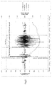
- Figure 1 is a graph visualizing parameters during heat exchange over a plate and shell heat exchanger manufactured and sold under the name Packinox by the applicant.
- the heat exchanger operates as a preheater in catalytic reforming where an upwards flow of liquid naphtha and recycled gaseous hydrogen is heated by the effluent from a reforming reactor, which effluent comprises reformates and hydrogen.
- Figure 1 includes a region with unsatisfactory lifting, which is marked with Bad lifting.
- Figure 2 is a similar graph as figure 1 showing the flow rate of liquid naphtha, the flow rate of recycled gaseous hydrogen and the lifting ratio but also the time derivative of the hot end approach (dHAT/dt) in °C/minute over time in minutes.
- Figure 3 is also a similar graph as figure 1 showing the flow rate of liquid naphtha, the flow rate of recycled gaseous hydrogen and the lifting ratio but also the time derivative of the feed side pressure drop (ddpfeed/dt) multiplied with 100 in bar/minute over time in minutes.
- the hot end approach as well as the pressure drop of the first fluid varies when the lifting force is too small as shown in figure 1 . It has been realized that the hot end approach as well as the pressure drop of the first fluid can be used to indicate unsatisfactory lifting.
- the determining that the lifting force is insufficient may be based on the variation of the hot end approach and/or the variation of the pressure drop. If the variation of the hot end approach and/or the pressure drop is large it can be considered that the lifting force is insufficient. Major variations of the hot end approach and/or the pressure drop can be considered to indicate insufficient lifting force.
- the determining that the lifting force is insufficient is based on the time derivative of the hot end approach and/or the time derivative of the pressure drop.
- the time derivate reflects the variation of the hot end approach and pressure drop, respectively, over time.
- the variation of the hot end approach and the pressure drop of the first fluid is identified by studying the time derivatives thereof and thereby it can be determined if the lifting is insufficient.
- the variation of the hot end approach and the pressure drop of the first fluid when the lifting force is too small is even more clear for the derivatives as seen in figures 2 and 3 than for the hot end approach and pressure drop themselves visualized in figure 1 .
- the time derivative gives an improved evaluation of if the lifting is insufficient.
- the lifting force is insufficient if the absolute value of the time derivative of the hot end approach exceeds a predefined primary threshold value (A1) (101) and/or if the absolute value of the time derivative of the pressure drop exceeds a predefined primary limit value (B1) (102).
- the time derivative is compared to a predefined value in order to evaluate if the variation is so great that the lifting force is insufficient.
- the time derivative of the hot end approach is compared to a predefined primary threshold value (A1).
- the time derivative of the pressure drop of the first fluid is compared to a predefined primary limit value (B1). It is not decisive if the hot end approach and the pressure drop is increasing or decreasing.
- the lifting force is insufficient if the absolute value of the time derivate of the hot end approach is greater than the predefined primary threshold value (A1) (101) or if the absolute value of the time derivative of the pressure drop of the first fluid is greater than the predefined primary limit value (B1) (102) or if both the absolute value of the time derivate of the hot end approach is greater than the predefined primary threshold value (A1) (101) and the absolute value of the time derivative of the pressure drop of the first fluid is greater than the predefined primary limit value (B1) (102).
- the lifting force is insufficient if any, i.e.
- the time derivative is the first order time derivative or the second order time derivative. In one aspect, the time derivative is the first order time derivative.
- the first order time derivative of the hot end approach is shown in figure 2 .
- the first order time derivative of the pressure drop of the first fluid is shown in figure 3 .
- the predefined primary threshold value (A1) for the first order time derivative may be 1°C/min.
- the predefined primary limit value (B1) for the first order time derivative may be 0.005 bar/min.
- the method further comprises determining that the lifting force risk being insufficient based on hot end approach and/or on pressure drop.
- the method can thereby indicate that there is a risk that the lifting force will be too low.
- variations of the hot end approach and the pressure drop indicate reduced lifting and risk of insufficient lifting force.
- the determination of risk for insufficient lifting force gives the possibility to optimize the process.
- the process should be monitored and the operating parameters should preferably be adjusted to increase the lifting force. Thereby, it is possible to avoid further decrease of the lifting ratio and to avoid problematic and inefficient operation as well as stoppage and interrupted operation.
- the determining that the lifting force risk being insufficient is based on the time derivative of the hot end approach and/or the time derivative of the pressure drop.
- the time derivative of the hot end approach and the pressure drop can be used to evaluate variations of the hot end approach and pressure drop of the first fluid and thereby to determine risk of insufficient lifting force.
- the lifting force risk being insufficient if the absolute value of the time derivative of the hot end approach is lower than the predefined primary threshold value (A1) (101') and/or if the absolute value of the time derivative of the pressure drop is lower than the predefined primary limit value (B1) (102').
- the comparison of the time derivative of the hot end approach and/or the pressure drop with a restriction value gives an easy determination of if there exists a risk for insufficient lifting.
- the lifting force risk being insufficient if the absolute value of the time derivative of the hot end approach is equal to or lower than the predefined primary threshold value (A1) (101') and/or if the absolute value of the time derivative of the pressure drop is equal to or lower than the predefined primary limit value (B1) (102').
- the criterion that the absolute value of the time derivative of the hot end approach is equal to or lower than the predefined primary threshold value (A1) (101') is shown as fulfilled when
- the lifting force risk being insufficient if both the absolute value of the time derivative of the hot end approach is lower than the predefined primary threshold value (A1) and the absolute value of the time derivative of the pressure drop is lower than the predefined primary limit value (B1).
- A1 the predefined primary threshold value
- B1 the predefined primary limit value
- the method further comprises determining that the lifting force is sufficient based on hot end approach and/or on pressure drop.
- the determining that the lifting force is sufficient may be based on the variation of the hot end approach and/or the pressure drop of the first fluid. If the variation of the hot end approach and/or the variation of the pressure drop is small it can be considered that the lifting force is sufficient. Minor or absence of variations of the hot end approach and/or the pressure drop can be considered to indicate sufficient lifting force. Determination of that the lifting force is sufficient implies that the certainty of the operation of the process is increased. A determination showing that the lifting force is sufficient gives an indication of that the process is operating properly and that there is no need for adjusting the operating parameters for lifting force purposes.
- the operating parameters can be adjusted in order to optimize the process and improve the efficiency and a further evaluation of the lifting force can be performed to determine if the lifting force still is sufficient or if the adjusted parameters have caused insufficient or risk for insufficient lifting force.
- the determining that the lifting force is sufficient is based on the time derivative of the hot end approach and/or the time derivative of the pressure drop.
- the time derivate reflects the variation of the hot end approach and pressure drop, respectively, over time.
- the variation of the hot end approach and the pressure drop of the first fluid is identified by studying the time derivatives thereof and thereby it can be determined if the lifting is sufficient.
- the variation of the hot end approach and the pressure drop of the first fluid when the lifting force is too small compared to when the lifting force is acceptable is even more clear for the derivatives as seen in figures 2 and 3 than for the hot end approach and pressure drop themselves visualized in figure 1 and thus the time derivative gives an improved evaluation of if the lifting is sufficient.
- the lifting force is sufficient if the absolute value of the time derivative of the hot end approach is lower than a predefined secondary threshold value (A2) (103) and/or if the absolute value of the time derivative of the pressure drop is lower than a predefined secondary limit value (B2) (104).
- the time derivative is compared to a predefined value in order to evaluate if the variation is so small that the lifting force is sufficient.
- the time derivative of the hot end approach is compared to a predefined secondary threshold value (A2) and the time derivative of the pressure drop of the first fluid is compared to a predefined secondary limit value (B2).
- the predefined secondary threshold value (A2) is lower than the predefined primary threshold value (A1), i.e. A2 ⁇ A1, which is visualized in figure 6A .
- the predefined secondary limit value (B2) is lower than the predefined primary limit value (B1), i.e. B2 ⁇ B1, which is visualized in figure 6B .
- the lifting force is sufficient if the absolute value of the time derivative of the hot end approach is equal to or lower than a predefined secondary threshold value (A2) (103) and/or if the absolute value of the time derivative of the pressure drop is equal to or lower than a predefined secondary limit value (B2) (104).
- A2) a predefined secondary threshold value
- B2 a predefined secondary limit value
- the lifting force is sufficient if the absolute value of the time derivate of the hot end approach is smaller than the predefined secondary threshold value (A2) (103) or if the absolute value of the time derivative of the pressure drop of the first fluid is smaller than the predefined secondary limit value (B2) (104) or if both the absolute value of the time derivate of the hot end approach is smaller than the predefined secondary threshold value (A2) (103) and the absolute value of the time derivative of the pressure drop of the first fluid is smaller than the predefined secondary limit value (B2) (104).
- the lifting force is sufficient if both the absolute value of the time derivate of the hot end approach is smaller than the predefined secondary threshold value (A2) and the absolute value of the time derivative of the pressure drop of the first fluid is smaller than the predefined secondary limit value (B2).
- A2 the predefined secondary threshold value
- B2 the predefined secondary limit value
- This latter criterion is more strict and reduces the risk of considering the lifting to be sufficient when it in reality not is sufficient since both subcriteria regarding hot end approach and pressure drop have to be fulfilled to give a determination concluding that the lifting is sufficient.
- the operation can continue without any change of the operating conditions.
- This strict determination of when the lifting force is sufficient is visualized in figure 5 , where it is described that when both of the criteria
- a relevant value of the predefined secondary threshold value (A2) for the first order time derivative may be 0.05°C/min.
- a relevant value of the predefined secondary limit value (B2) for the first order time derivative may be 0.001 bar/min.
- the lifting force risk being insufficient if the absolute value of the time derivative of the hot end approach exceeds the predefined secondary threshold value (A2) (103') and is lower than the predefined primary threshold value (A1) (101') and/or if the absolute value of the time derivative of the pressure drop exceeds the predefined secondary limit value (B2) (104') and is lower than the predefined primary limit value (B1) (102').
- the lifting force risk being insufficient gives a strong incentive to monitor the operation conditions and preferably to adjust the operating parameters such that the lifting force is increased. Thereby, the efficiency of the process can be increased and wear, interruptions and breakdowns can be avoided.
- it is determined that the lifting force risk being insufficient if the absolute value of the time derivative of the hot end approach exceeds the predefined secondary threshold value (A2) (103') and is equal to or lower than the predefined primary threshold value (A1) (101') and/or if the absolute value of the time derivative of the pressure drop exceeds the predefined secondary limit value (B2) (104') and is equal to or lower than the predefined primary limit value (B1) (102').
- the lifting force risk being insufficient if the absolute value of the time derivative of the hot end approach falls within the range between the predefined secondary threshold value (A2) and the predefined primary threshold value (A1), possibly including the predefined primary threshold value (A1), and/or if the absolute value of the time derivative of the pressure drop falls within the range between the predefined secondary limit value (B2) and the predefined primary limit value (B1), possibly including the predefined primary limit value (B1). It is determined that there is a risk for the lifting force to be insufficient if it not is determined that the lifting force is insufficient and not is determined that the lifting force is sufficient. Preferably, it is determined that the lifting force risk being insufficient if any, i.e.
- lifting ratio is defined as the ratio between forces acting upwards on the liquid phase and forces acting downwards on the liquid phase. In order to have sufficient lifting, the lifting ratio should be larger than one. It is possible to calculate the lifting ratio in design conditions since the necessary data is available. To determine the actual lifting ratio, the actual operating conditions have to be measured. However, it is difficult to measure and obtain all actual operating parameters for the actual operating condition. It has been realized that an estimation of the actual lifting ratio can be obtained by calculating the lifting ratio in design conditions and correct the result using a comparison between the design and the actual conditions.
- L base is the lifting ratio calculated in design conditions but with actual operating flow rate
- p RG is the pressure of gas phase at the first inlet to the heat exchanger (recycle gas pressure)
- Q RG is the mass flow rate of the gas phase at the first inlet to the heat exchanger (recycle gas flow rate)
- Q L is the mass flow rate of the liquid phase at the first inlet to the heat exchanger (liquid feed flow rate)
- MW RG is the molar mass of the gas phase at the first inlet to the heat exchanger (recycle gas molar mass)
- T RG is the temperature of the gas phase at the first
- the determination of too low or risk for too low lifting force may be combined with the criterion for the estimated actual lifting ratio, L.
- the determination that the lifting force is insufficient and the determination that the lifting force risk being insufficient if the absolute value of the time derivative of the hot end approach is lower than the predefined primary threshold value (A1) and/or if the absolute value of the time derivative of the pressure drop is lower than the predefined primary limit value (B1), be combined with the criterion for the estimated actual lifting ratio, L.
- the estimated actual lifting ratio L is found to be higher than 1, i.e. L>1, then it can be concluded that the lifting force is sufficient and that the operation can continue without any change of the operating conditions. If the estimated actual lifting ratio L is found to be lower than 1, the lifting is further evaluated based on the hot end approach and/or the pressure drop.
- the lifting force is insufficient if the absolute value of the time derivate of the hot end approach is greater than the predefined primary threshold value (A1) or if the absolute value of the time derivative of the pressure drop of the first fluid is greater than the predefined primary limit value (B1) or if both the absolute value of the time derivate of the hot end approach is greater than the predefined primary threshold value (A1) and the absolute value of the time derivative of the pressure drop of the first fluid is greater than the predefined primary limit value (B1). Then, i.e. when it is determined that the lifting force is insufficient, measures to correct the operating conditions should be performed immediately or the process should be stopped.
- the lifting force risk being insufficient if the absolute value of the time derivative of the hot end approach is lower than the predefined primary threshold value (A1) and/or if the absolute value of the time derivative of the pressure drop is lower than the predefined primary limit value (B1). Then, i.e. when it is determined that the lifting force risk being insufficient, the operation should be followed and monitored more closely and preferably should the operating conditions be changed to improve the lifting. In one aspect, if the estimated actual lifting ratio L is found to be equal to or lower than 1, the lifting is further evaluated based on the hot end approach and/or the pressure drop.
- Determination that the lifting force is sufficient may be performed without evaluation criterion for the estimated actual lifting ratio, L. Such a determination is shown in figure 5 .
- Figures 6A visualizes the relation between the predefined primary threshold value (A1) and the predefined secondary threshold value (A2) for the time derivative of the hot end approach and the different regions for the criteria of insufficient, risk of insufficient and sufficient lifting force in a version, where only the time derivative of the hot end approach is considered.
- Figures 6B visualizes the relation between the predefined primary limit value (B1) and the predefined secondary limit value (B2) for the time derivative of the pressure drop of the first fluid and the different regions for the criteria of insufficient, risk of insufficient and sufficient lifting force in a version, where only the time derivative of the pressure drop is considered.
- the second fluid may have a higher temperature than the first fluid such that heat is transferred from the second fluid to the first fluid.
- the first fluid may flow on the cold side of the heat exchanger.
- the second fluid may flow on the warm side of the heat exchanger.
- the lifting force of the gas phase of the first fluid acting on the liquid phase of the first fluid must be larger than the gravitational force and possibly the frictional force acting on the liquid phase at the first inlet of the heat exchanger.
- the lifting force will be increased during the flow of the first fluid through the heat exchanger and the liquid phase of the first fluid may even evaporate during flow of the first fluid through the heat exchanger.
- the first fluid may consist of one fluid or be a mixture of fluids.
- the gas phase of the first fluid may comprise one fluid and the liquid phase of the first fluid may comprise the same fluid or a different fluid.
- the first fluid may comprise a primary subfluid and a secondary subfluid.
- the gas phase of the first fluid may comprise the primary subfluid and the liquid phase of the first fluid may comprise the secondary subfluid.
- the heat exchanger may be a preheating heat exchanger in catalytic reforming.
- a preheating heat exchanger in catalytic reforming an upward flow of liquid naphtha and recycled gaseous hydrogen is heated by the effluent from the reforming reactor.
- the effluent comprises e.g. reformates and hydrogen.
- the gas phase may comprise hydrogen and the liquid phase may comprise naphtha.
- the primary subfluid of the first fluid may be hydrogen and the secondary subfluid of the first fluid may be naphtha.
- the second fluid may be effluent from the reforming reactor, which comprises e.g. reformates and hydrogen.
- the heat exchanger comprises a partition separating the first fluid from the second fluid.
- the partition defines a heat exchanger area transferring heat from the second fluid to the first fluid.
- the heat exchanger comprises a first inlet and a first outlet arranged to allow the first fluid to flow on a first side of the partition.
- the heat exchanger comprises a second inlet and a second outlet arranged to allow the second fluid to flow on a second side of the partition.
- the heat exchanger comprises a first passage from the first inlet to the first outlet.
- the heat exchanger comprises a second passage from the second inlet to the second outlet.
- the partition separates the first passage form the second passage.
- the partition may for example be a heat exchanger plate, preferably a plurality of heat exchanger plates or a heat exchanger tube, preferably a plurality of heat exchanger tubes, which tube(s) may be enclosed in a shell e.g. in the form of a pressure vessel.
- the heat exchanger may be any type of heat exchanger as long as it is operating with a substantially vertical flow for the first fluid.
- the heat exchanger may for example be a plate heat exchanger, a tube heat exchanger, a shell and plate heat exchanger or a plate and shell heat exchanger.
- the heat exchanger may for example be a welded heat exchanger, a brazed heat exchanger or a gasketed heat exchanger.
- the first inlet may comprise two first subinlets, where the gas phase enters one of the subinlets and the liquid phase enters the other subinlet.
- the gas phase and the liquid phase may be mixed shortly after entering the subinlets.
- the method comprises measuring an outlet temperature of the first fluid at the first outlet, measuring an inlet temperature of the second fluid at the second inlet and calculating the hot end approach as the difference between the inlet temperature of the second fluid and the outlet temperature of the first fluid.
- the hot end approach is the difference between the inlet temperature of the second fluid and the outlet temperature of the first fluid.
- the method comprises determining a pressure difference between an inlet pressure of the first fluid at the first inlet and an outlet pressure of the first fluid at the first outlet and setting the pressure drop as the determined pressure difference.
- the determining of a pressure difference comprises measuring a pressure difference between the inlet pressure of the first fluid at the first inlet and the outlet pressure of the first fluid at the first outlet. This measuring of a pressure difference could be performed by a differential pressure sensor.
- the determining of a pressure difference comprises measuring the inlet pressure of the first fluid at the first inlet, measuring the outlet pressure of the first fluid at the first outlet and calculating the pressure difference as the difference between the inlet pressure of the first fluid and the outlet pressure of the first fluid.
- the pressure drop of the first fluid is the difference between the inlet pressure of the first fluid and the outlet pressure of the first fluid, i.e. the difference between the inlet pressure of the first fluid at the first inlet and the outlet pressure of the first fluid at the first outlet.
- the partition is substantially vertically arranged.
- the two-phase flow is substantially vertical.
- the partition is substantially vertically arranged over a substantial portion of the heat exchanger area.
- the partition is substantially parallel to a vertical axis.
- the heat exchanger is operating with counter-current flow or cross flow.
- the present invention also relates to a control unit for evaluating lifting force of a gas phase of a substantially vertical upward two-phase flow of a first fluid in a heat exchanger.
- the first fluid comprises the gas phase and a liquid phase.
- the control unit is configured to determine that the lifting force of the gas phase is insufficient for lifting the liquid phase based on hot end approach of the heat exchanger and/or on pressure drop of the first fluid over the heat exchanger.
- the control unit may include the same aspects, features and alternatives as the method and may have the same advantages and effects as the method.
- the control unit may be a central control system controlling the operation of the heat exchanger or a process in which the heat exchanger is included or a control unit controlling and/or monitoring the heat exchanger.
- the control unit may include a processing unit of a conventional type and may be capable of carrying out instructions of a computer program.
- the control unit may also comprise a memory unit in which the predefined values (A1, A2, B1, B2) and/or the computer program may be stored.
- the method according to the various embodiments disclosed herein may be implemented by a data processing device, such as the control unit or the processing unit thereof.
- the present invention further relates to a heat exchanger assembly comprising a heat exchanger and a control unit according to above.
- the control unit is for evaluating lifting force of a gas phase of a substantially vertical upward two-phase flow of a first fluid in the heat exchanger.
- the first fluid comprises the gas phase and a liquid phase.
- the control unit is configured to determine that the lifting force of the gas phase is insufficient for lifting the liquid phase based on hot end approach of the heat exchanger and/or on pressure drop of the first fluid over the heat exchanger.
- the control unit may include the same aspects, features and alternatives as the method and may have the same advantages and effects as the method.
- the heat exchanger comprises a partition separating the first fluid from a second fluid and defining a heat exchanger area transferring heat from the second fluid to the first fluid.
- the heat exchanger comprises a first inlet and a first outlet arranged to allow the first fluid to flow on a first side of the partition and a second inlet and a second outlet arranged to allow the second fluid to flow on a second side of the partition.
- the partition is arranged to allow substantially vertical upward flow of the first fluid.
- the heat exchanger assembly may include the same aspects, features and alternatives as the control unit and the method and may have the same advantages and effects as the control unit and the method.
Landscapes
- Chemical & Material Sciences (AREA)
- Engineering & Computer Science (AREA)
- Organic Chemistry (AREA)
- Chemical Kinetics & Catalysis (AREA)
- Life Sciences & Earth Sciences (AREA)
- Sustainable Development (AREA)
- Physics & Mathematics (AREA)
- Thermal Sciences (AREA)
- Mechanical Engineering (AREA)
- General Engineering & Computer Science (AREA)
- Air-Conditioning For Vehicles (AREA)
Abstract
Description
- The invention relates to a method and a control unit for evaluating lifting force of a gas phase of a substantially vertical upward two-phase flow of a first fluid in a heat exchanger and a heat exchanger assembly comprising a heat exchanger and the control unit.
- Some heat exchangers are operating with a vertical two-phase flow of at least one of the fluids, which comprises a gas phase and a liquid phase typically distributed as droplets in the gas phase. For example in catalytic reforming a preheating heat exchanger is used in which an upward flow of liquid naphtha and recycled gaseous hydrogen is heated by the effluent from the reforming reactor. The effluent comprises e.g. reformates and hydrogen.
- The liquid phase of the fluid must be driven upwards by the gas phase of the fluid. Thus, in order to move the liquid phase upwards, on each droplet of the liquid phase the aerodynamic lifting force must be greater than the gravitational force or if the droplet is in contact with the wall greater than the sum of the gravitational force and the frictional force of the wall. The lifting force of the gas phase acting on the liquid phase must be larger than the gravitational force and possibly the frictional force acting on the liquid phase.
- The lifting force is dependent on for example the fluid and its characteristics, the geometry of the flow path of the fluid through the heat exchanger and the operating conditions, such as temperature, pressure, flow rates, etc.
- Sufficient lifting force can be obtained by e.g. having a high flow rate of the gas phase and a high temperature of the fluid. Also a heavy gas having a high molar mass in the gas phase increases the lifting force.
- However, to obtain a high efficiency and a low pressure drop the temperature and molar mass should preferably be kept down. There are also constraints, such as pressure drop and compressor limitations, that incite operators to lower the gas flow rate. Thus, it is optimal to regulate the parameters such that lifting force is sufficient but not unnecessarily excessive. Further, it is important to obtain a good distribution of fluids over the heat exchanging area of a heat exchanger to improve the efficiency and avoid mechanical damages. Consequently, there is a need for optimizing the operating parameters such that a sufficient lifting force of the gas phase is obtained.
- One object of the invention is to enable optimization of operating parameters. One object of the invention is to improve efficiency of a heat exchanger. One object is to enable increased efficiency of a heat exchanger with satisfactory lifting force. One object is to avoid interruption of a heat exchanging process and breakdowns of heat exchanging equipment. One object is to anticipate operating problems. One object is to detect insufficient lifting force.
- These and further objects are achieve by a method for evaluating lifting force of a gas phase of a substantially vertical upward two-phase flow of a first fluid in a heat exchanger. The first fluid comprises the gas phase and a liquid phase. The method comprises determining that the lifting force of the gas phase is insufficient for lifting the liquid phase based on hot end approach of the heat exchanger and/or on pressure drop of the first fluid over the heat exchanger. By determining that the lifting force is insufficient it is possible to identify and foresee problematic, harmful and inefficient operation of the heat exchanger. When it is determined that the lifting force is insufficient the operating parameters, such as the flow rate of the gas phase and the inlet temperatures of the liquid phase and the gas phase, could be adjusted to increase the lifting ratio and thereby increase the efficiency of the process, reduce the wear on the equipment and avoid interruption of the process and breakdown. Breakdown and unnecessary wear can also be avoided by stopping the process. Preferred variants of the method are defined in the associated dependent claims.
- The above and further objects as well as the above advantages and effects are also achieved by a control unit for evaluating lifting force of a gas phase of a substantially vertical upward two-phase flow of a first fluid in a heat exchanger. The first fluid comprises the gas phase and a liquid phase. The control unit is configured to determine that the lifting force of the gas phase is insufficient for lifting the liquid phase based on hot end approach of the heat exchanger and/or on pressure drop of the first fluid over the heat exchanger. The control unit may implement any of the variants of the method defined in the dependent claims related to the method.
- The above and further objects as well as the above advantages and effects are also achieved by a heat exchanger assembly comprising a heat exchanger and the above control unit. The heat exchanger comprises a partition separating the first fluid from a second fluid and defining a heat exchanger area transferring heat from the second fluid to the first fluid. The heat exchanger comprises a first inlet and a first outlet arranged to allow the first fluid to flow on a first side of the partition and a second inlet and a second outlet arranged to allow the second fluid to flow on a second side of the partition. The partition is arranged to allow substantially vertical upward flow of the first fluid. The heat exchanger assembly may implement any of the variants of the method defined in the dependent claims related to the method.
- Still other objectives, features, aspects and advantages of the method, the control unit and the heat exchanger assembly will appear from the following detailed description as well as from the drawings.
- Embodiments of the invention will now be described with reference to the accompanying schematic drawings, in which
-
Fig. 1 is a graph of operating parameters of a heat exchanger operating with two-phase flow over time including a time period of unsatisfactory lifting, -
Fig. 2 is a graph of some of the operating parameters shown infigure 1 , where also the time derivative of the hot end approach is shown, -
Fig. 3 is a graph of some of the operating parameters shown infigure 1 , where also the time derivative of the pressure drop of the first fluid is shown. -
Fig. 4 is a flow chart of evaluation criteria according to one embodiment. -
Fig. 5 is a flow chart of evaluation criteria for another embodiment. -
Fig. 6A is visualization of evaluation criteria for the hot end approach according to the embodiment offig. 5 . -
Fig. 6B is visualization of evaluation criteria for the pressure drop according to the embodiment offig. 5 . - As stated above, the present invention relates to a method for evaluating lifting force of a gas phase of a substantially vertical upward two-phase flow of a first fluid in a heat exchanger. The first fluid comprises the gas phase and a liquid phase. The first fluid flows upwards due to the raising force of the gas phase. The gas phase brings the liquid phase upwards. The invention aims at assisting in controlling the operating conditions such that the liquid phase is brought upwards through the heat exchanger by the gas phase. This is achieved by determining that the lifting force of the gas phase is insufficient for lifting the liquid phase based on hot end approach of the heat exchanger and/or on pressure drop of the first fluid over the heat exchanger. In other words, the determining if the lifting force of the gas phase is insufficient for lifting the liquid phase is either based on hot end approach of the heat exchanger or on pressure drop of the first fluid over the heat exchanger or on a combination of hot end approach of the heat exchanger and pressure drop of the first fluid over the heat exchanger. By determining that the lifting force is insufficient it is possible to identify and foresee problematic, harmful and inefficient operation of the heat exchanger. When it is determined that the lifting force is insufficient the operating parameters, such as the flow rate of the gas phase and the inlet temperatures of the liquid phase and the gas phase, should be adjusted to increase the lifting ratio or in critical situations it may even be necessary to stop the process. Thus, the determination of insufficient lifting increases efficiency, reduces wear and avoids interruption and breakdown. If it not is determined that the lifting force is insufficient, the operating parameters may be adjusted to optimize the process and improve the efficiency and the lifting force can be further evaluated to see if the lifting force is insufficient with the adjusted parameters.
- The liquid phase of the first fluid must be driven upwards by the gas phase of the fluid. Thus, in order to move the liquid phase upwards, on each droplet of the liquid phase the aerodynamic lifting force must be greater than the gravitational force or if the droplet is in contact with the wall greater than the sum of the gravitational force and the frictional force. The lifting force of the gas phase acting on the liquid phase must be larger than the gravitational force and possibly the frictional force acting on the liquid phase. There can be determined a lifting ratio defined as the ratio between forces acting upwards on the liquid phase, such as the lifting force of the gas phase, and the forces acting downwards on the liquid phase, such as the gravitational force of the liquid phase and possibly the wall frictional force of the liquid phase. In order to have sufficient lifting, the lifting ratio should be larger than one.
-
Figure 1 is a graph visualizing parameters during heat exchange over a plate and shell heat exchanger manufactured and sold under the name Packinox by the applicant. The heat exchanger operates as a preheater in catalytic reforming where an upwards flow of liquid naphtha and recycled gaseous hydrogen is heated by the effluent from a reforming reactor, which effluent comprises reformates and hydrogen. The graph offigure 1 includes a plot of the flow rate of liquid naphtha (Naphtha rate) in t/h (tonne/hour=1000 kg/hour), the flow rate of recycled gaseous hydrogen (RG rate) in t/h (tonne/hour=1000 kg/hour), the hot end approach in °C, the lifting ratio calculated according to the below estimated actual lifting ratio (dimensionless) and the pressure drop over the heat exchanger for the mixed liquid naphtha and recycled gaseous hydrogen (Feed side pressure drop) in bar over time in minutes.Figure 1 includes a region with unsatisfactory lifting, which is marked with Bad lifting. -
Figure 2 is a similar graph asfigure 1 showing the flow rate of liquid naphtha, the flow rate of recycled gaseous hydrogen and the lifting ratio but also the time derivative of the hot end approach (dHAT/dt) in °C/minute over time in minutes.Figure 3 is also a similar graph asfigure 1 showing the flow rate of liquid naphtha, the flow rate of recycled gaseous hydrogen and the lifting ratio but also the time derivative of the feed side pressure drop (ddpfeed/dt) multiplied with 100 in bar/minute over time in minutes. - When the lifting ratio decreases and thereby the lifting force becomes too small also the flow rate of the gas phase decreases as seen in
figure 1 . It has been found that the hot end approach as well as the pressure drop of the first fluid varies when the lifting force is too small as shown infigure 1 . It has been realized that the hot end approach as well as the pressure drop of the first fluid can be used to indicate unsatisfactory lifting. The determining that the lifting force is insufficient may be based on the variation of the hot end approach and/or the variation of the pressure drop. If the variation of the hot end approach and/or the pressure drop is large it can be considered that the lifting force is insufficient. Major variations of the hot end approach and/or the pressure drop can be considered to indicate insufficient lifting force. - In one aspect, the determining that the lifting force is insufficient is based on the time derivative of the hot end approach and/or the time derivative of the pressure drop. The time derivate reflects the variation of the hot end approach and pressure drop, respectively, over time. Thus, the variation of the hot end approach and the pressure drop of the first fluid is identified by studying the time derivatives thereof and thereby it can be determined if the lifting is insufficient. The variation of the hot end approach and the pressure drop of the first fluid when the lifting force is too small is even more clear for the derivatives as seen in
figures 2 and3 than for the hot end approach and pressure drop themselves visualized infigure 1 . Thereby, the time derivative gives an improved evaluation of if the lifting is insufficient. - In one aspect, it is determined that the lifting force is insufficient if the absolute value of the time derivative of the hot end approach exceeds a predefined primary threshold value (A1) (101) and/or if the absolute value of the time derivative of the pressure drop exceeds a predefined primary limit value (B1) (102). The time derivative is compared to a predefined value in order to evaluate if the variation is so great that the lifting force is insufficient. The time derivative of the hot end approach is compared to a predefined primary threshold value (A1). The time derivative of the pressure drop of the first fluid is compared to a predefined primary limit value (B1). It is not decisive if the hot end approach and the pressure drop is increasing or decreasing. It is the magnitude of the variation that is relevant to detect insufficient lifting and therefore the absolute value of the time derivative is studied. By comparing the time derivative of the hot end approach and/or the pressure drop with a specific restriction value gives an easy and reliable determination of if the lifting force is insufficient. In
figures 4 and5 the criterion related that the absolute value of the time derivative of the hot end approach exceeds a predefined primary threshold value (A1) (101) is shown as fulfilled when |dHAT/dt|>A1 is confirmed and thereby answered with a Yes (Y). The criterion that the absolute value of the time derivative of the pressure drop exceeds a predefined primary limit value (B1) (102) is infigures 4 and5 shown as fulfilled when |ddpfeed/dt|>B1 is confirmed and thereby answered with a Yes (Y). Preferably, it is determined that the lifting force is insufficient if the absolute value of the time derivate of the hot end approach is greater than the predefined primary threshold value (A1) (101) or if the absolute value of the time derivative of the pressure drop of the first fluid is greater than the predefined primary limit value (B1) (102) or if both the absolute value of the time derivate of the hot end approach is greater than the predefined primary threshold value (A1) (101) and the absolute value of the time derivative of the pressure drop of the first fluid is greater than the predefined primary limit value (B1) (102). Thus, preferably it is determined that the lifting force is insufficient if any, i.e. at least one, of the criteria the absolute value of the time derivate of the hot end approach is greater than the predefined primary threshold value (A1) (101) and the absolute value of the time derivative of the pressure drop of the first fluid is greater than the predefined primary limit value (B1) (102) is fulfilled. This gives a strict determination of when the lifting force is insufficient that reduces the risk of not classify an insufficient lifting force as insufficient since it only is required that one of the two restriction value criteria related to hot end approach and pressure drop, respectively, is fulfilled. This strict determination of when the lifting force is insufficient is visualized infigures 4 and5 , where it is described that when any of the criteria |dHAT/dt|>A1? (101) and |ddpfeed/dt|>B1? (102) is answered with a Yes it is determined that the lifting force is insufficient. - In one aspect, the time derivative is the first order time derivative or the second order time derivative. In one aspect, the time derivative is the first order time derivative. The first order time derivative of the hot end approach is shown in
figure 2 . The first order time derivative of the pressure drop of the first fluid is shown infigure 3 . - The predefined primary threshold value (A1) for the first order time derivative may be 1°C/min. The predefined primary limit value (B1) for the first order time derivative may be 0.005 bar/min. These values have been found to be suitable restrictions for insufficient lifting.
- In one aspect, the method further comprises determining that the lifting force risk being insufficient based on hot end approach and/or on pressure drop. The method can thereby indicate that there is a risk that the lifting force will be too low. As explained above and seen in
figure 1 , variations of the hot end approach and the pressure drop indicate reduced lifting and risk of insufficient lifting force. The determination of risk for insufficient lifting force gives the possibility to optimize the process. When it is determined that there is a risk for insufficient lifting the process should be monitored and the operating parameters should preferably be adjusted to increase the lifting force. Thereby, it is possible to avoid further decrease of the lifting ratio and to avoid problematic and inefficient operation as well as stoppage and interrupted operation. - In one aspect, the determining that the lifting force risk being insufficient is based on the time derivative of the hot end approach and/or the time derivative of the pressure drop. As explained above, the time derivative of the hot end approach and the pressure drop can be used to evaluate variations of the hot end approach and pressure drop of the first fluid and thereby to determine risk of insufficient lifting force.
- In one aspect, it is determined that the lifting force risk being insufficient if the absolute value of the time derivative of the hot end approach is lower than the predefined primary threshold value (A1) (101') and/or if the absolute value of the time derivative of the pressure drop is lower than the predefined primary limit value (B1) (102'). The comparison of the time derivative of the hot end approach and/or the pressure drop with a restriction value gives an easy determination of if there exists a risk for insufficient lifting. In one aspect, it is determined that the lifting force risk being insufficient if the absolute value of the time derivative of the hot end approach is equal to or lower than the predefined primary threshold value (A1) (101') and/or if the absolute value of the time derivative of the pressure drop is equal to or lower than the predefined primary limit value (B1) (102'). In
figures 4 and5 the criterion that the absolute value of the time derivative of the hot end approach is equal to or lower than the predefined primary threshold value (A1) (101') is shown as fulfilled when |dHAT/dt|>A1 is false and thereby answered with a No (N). The criterion that the absolute value of the time derivative of the pressure drop is equal to or lower than the predefined primary limit value (B1) (102') is infigures 4 and5 shown as fulfilled when |ddpfeed/dt|>B1 is false and thereby answered with a No (N). Infigure 4 , the determination that the criterion |dHAT/dt|>A1 is false and the criterion |ddpfeed/dt|>B1 is false is enough for concluding that the lifting force is in the risk zone of being insufficient, while infigure 5 further evaluation is performed. Preferably, it is determined that the lifting force risk being insufficient if both the absolute value of the time derivative of the hot end approach is lower than the predefined primary threshold value (A1) and the absolute value of the time derivative of the pressure drop is lower than the predefined primary limit value (B1). Thereby, it is determined that there is a risk for insufficient lifting if the time derivatives of both the hot end approach and the pressure drop are smaller than their respective restriction values, while it is determined that the lifting is insufficient if the time derivative of any of the hot end approach and the pressure drop exceeds its respective restriction value according to the above preferred version of determining that the lifting force is insufficient. This determination of when there is a risk for insufficient lifting force is visualized infigures 4 and5 , where it is described that when both of the criteria |dHAT/dt|>A1? (101') and |ddpfeed/dt|>B1? (102') is answered with a No it is determined that the lifting force risk being insufficient. Infigure 4 , where it previously in the method has been concluded that the estimated actual lifting force not is larger than one (L not larger than 1, see further below), it is directly determined that there is a risk of insufficient lifting force when both of the criteria |dHAT/dt|>A1? (101') and |ddpfeed/dt|>B1? (102') is answered with a No. Infigure 5 , it is further evaluated if there is a risk of insufficient lifting force that requires actions or closer monitoring when both of the criteria |dHAT/dt|>A1? (101') and |ddpfeed/dt|>B1? (102') is answered with a No. - In one aspect, the method further comprises determining that the lifting force is sufficient based on hot end approach and/or on pressure drop. The determining that the lifting force is sufficient may be based on the variation of the hot end approach and/or the pressure drop of the first fluid. If the variation of the hot end approach and/or the variation of the pressure drop is small it can be considered that the lifting force is sufficient. Minor or absence of variations of the hot end approach and/or the pressure drop can be considered to indicate sufficient lifting force. Determination of that the lifting force is sufficient implies that the certainty of the operation of the process is increased. A determination showing that the lifting force is sufficient gives an indication of that the process is operating properly and that there is no need for adjusting the operating parameters for lifting force purposes. On the other hand, when it is determined that the lifting force is sufficient, the operating parameters can be adjusted in order to optimize the process and improve the efficiency and a further evaluation of the lifting force can be performed to determine if the lifting force still is sufficient or if the adjusted parameters have caused insufficient or risk for insufficient lifting force.
- In one aspect, the determining that the lifting force is sufficient is based on the time derivative of the hot end approach and/or the time derivative of the pressure drop. The time derivate reflects the variation of the hot end approach and pressure drop, respectively, over time. Thus, the variation of the hot end approach and the pressure drop of the first fluid is identified by studying the time derivatives thereof and thereby it can be determined if the lifting is sufficient. The variation of the hot end approach and the pressure drop of the first fluid when the lifting force is too small compared to when the lifting force is acceptable is even more clear for the derivatives as seen in
figures 2 and3 than for the hot end approach and pressure drop themselves visualized infigure 1 and thus the time derivative gives an improved evaluation of if the lifting is sufficient. - In one aspect, it is determined that the lifting force is sufficient if the absolute value of the time derivative of the hot end approach is lower than a predefined secondary threshold value (A2) (103) and/or if the absolute value of the time derivative of the pressure drop is lower than a predefined secondary limit value (B2) (104). The time derivative is compared to a predefined value in order to evaluate if the variation is so small that the lifting force is sufficient. The time derivative of the hot end approach is compared to a predefined secondary threshold value (A2) and the time derivative of the pressure drop of the first fluid is compared to a predefined secondary limit value (B2). It is not decisive if the hot end approach and the pressure drop is increasing or decreasing, but it is the magnitude of the variation that is relevant to detect sufficient lifting and therefore the absolute value of the time derivative is studied. By comparing the time derivative of the hot end approach and/or the pressure drop with a predefined restriction value gives an easy determination of if the lifting force is sufficient. The predefined secondary threshold value (A2) is lower than the predefined primary threshold value (A1), i.e. A2<A1, which is visualized in
figure 6A . The predefined secondary limit value (B2) is lower than the predefined primary limit value (B1), i.e. B2<B1, which is visualized infigure 6B . In one aspect, it is determined that the lifting force is sufficient if the absolute value of the time derivative of the hot end approach is equal to or lower than a predefined secondary threshold value (A2) (103) and/or if the absolute value of the time derivative of the pressure drop is equal to or lower than a predefined secondary limit value (B2) (104). Infigure 5 the criterion related that the absolute value of the time derivative of the hot end approach is equal to or lower than a predefined secondary threshold value (A2) (103) is shown as fulfilled when |dHAT/dt|<A2 is confirmed and thereby answered with a Yes (Y). The criterion that the absolute value of the time derivative of the pressure drop is equal to or lower than a predefined secondary limit value (B2) (104) is infigure 5 shown as fulfilled when |ddpfeed/dt|<B2 is confirmed and thereby answered with a Yes (Y). It is determined that the lifting force is sufficient if the absolute value of the time derivate of the hot end approach is smaller than the predefined secondary threshold value (A2) (103) or if the absolute value of the time derivative of the pressure drop of the first fluid is smaller than the predefined secondary limit value (B2) (104) or if both the absolute value of the time derivate of the hot end approach is smaller than the predefined secondary threshold value (A2) (103) and the absolute value of the time derivative of the pressure drop of the first fluid is smaller than the predefined secondary limit value (B2) (104). Preferably, it is determined that the lifting force is sufficient if both the absolute value of the time derivate of the hot end approach is smaller than the predefined secondary threshold value (A2) and the absolute value of the time derivative of the pressure drop of the first fluid is smaller than the predefined secondary limit value (B2). This latter criterion is more strict and reduces the risk of considering the lifting to be sufficient when it in reality not is sufficient since both subcriteria regarding hot end approach and pressure drop have to be fulfilled to give a determination concluding that the lifting is sufficient. When it is determined that the lifting force is sufficient, the operation can continue without any change of the operating conditions. This strict determination of when the lifting force is sufficient is visualized infigure 5 , where it is described that when both of the criteria |dHAT/dt|<A2? (103) and |ddpfeed/dt|<B2? (104) is answered with a Yes it is determined that the lifting force is sufficient. - A relevant value of the predefined secondary threshold value (A2) for the first order time derivative may be 0.05°C/min. A relevant value of the predefined secondary limit value (B2) for the first order time derivative may be 0.001 bar/min.
- In one aspect, it is determined that the lifting force risk being insufficient if the absolute value of the time derivative of the hot end approach exceeds the predefined secondary threshold value (A2) (103') and is lower than the predefined primary threshold value (A1) (101') and/or if the absolute value of the time derivative of the pressure drop exceeds the predefined secondary limit value (B2) (104') and is lower than the predefined primary limit value (B1) (102'). By determining that there is a risk for insufficient lifting force when the time derivative of the hot end approach and/or pressure drop is within a range between two restrictive values, the reliability of the determination is high. That it is determined that the lifting force risk being insufficient gives a strong incentive to monitor the operation conditions and preferably to adjust the operating parameters such that the lifting force is increased. Thereby, the efficiency of the process can be increased and wear, interruptions and breakdowns can be avoided. In one aspect, it is determined that the lifting force risk being insufficient if the absolute value of the time derivative of the hot end approach exceeds the predefined secondary threshold value (A2) (103') and is equal to or lower than the predefined primary threshold value (A1) (101') and/or if the absolute value of the time derivative of the pressure drop exceeds the predefined secondary limit value (B2) (104') and is equal to or lower than the predefined primary limit value (B1) (102'). In
figure 5 the criterion that the absolute value of the time derivative of the hot end approach is equal to or lower than the predefined primary threshold value (A1) (101') is shown as fulfilled when |dHAT/dt|>A1 is false and thereby answered with a No (N) and the criterion that the absolute value of the time derivative of the hot end approach exceeds the predefined secondary threshold value (A2) (103') is shown as fulfilled when |dHAT/dt|≤A2 is false and thereby answered with a No (N). Infigure 5 the criterion that the absolute value of the time derivative of the pressure drop is equal to or lower than the predefined primary limit value (B1) (102') is shown as fulfilled when |ddpfeed/dt|>B1 is false and thereby answered with a No (N) and the criterion that the absolute value of the time derivative of the pressure drop exceeds the predefined secondary limit value (B2) (104') is shown as fulfilled when |ddpfeed/dt|≤B2 is false and thereby answered with a No (N). - In this aspect, it is determined that the lifting force risk being insufficient if the absolute value of the time derivative of the hot end approach falls within the range between the predefined secondary threshold value (A2) and the predefined primary threshold value (A1), possibly including the predefined primary threshold value (A1), and/or if the absolute value of the time derivative of the pressure drop falls within the range between the predefined secondary limit value (B2) and the predefined primary limit value (B1), possibly including the predefined primary limit value (B1). It is determined that there is a risk for the lifting force to be insufficient if it not is determined that the lifting force is insufficient and not is determined that the lifting force is sufficient. Preferably, it is determined that the lifting force risk being insufficient if any, i.e. at least one of, the criteria that the absolute value of the time derivative of the hot end approach exceeds the predefined secondary threshold value (A2) (103') and the absolute value of the time derivative of the pressure drop exceeds the predefined secondary limit value (B2) (104') and both the absolute value of the time derivative of the hot end approach is lower than the predefined primary threshold value (A1) (101') and the absolute value of the time derivative of the pressure drop is lower than the predefined primary limit value (B1) (102'). This determination of when the lifting force risk being insufficient is visualized in
figure 5 , where it is described that when both of the criteria |dHAT/dt|>A1? (101') and |ddpfeed/dt|>B1? (102') is answered with a No and any of the criteria |dHAT/dt|≤A2? (103') and |ddpfeed/dt|≤B2? (104') is answered with a No it is determined that the lifting force is insufficient. - As mentioned above, lifting ratio is defined as the ratio between forces acting upwards on the liquid phase and forces acting downwards on the liquid phase. In order to have sufficient lifting, the lifting ratio should be larger than one. It is possible to calculate the lifting ratio in design conditions since the necessary data is available. To determine the actual lifting ratio, the actual operating conditions have to be measured. However, it is difficult to measure and obtain all actual operating parameters for the actual operating condition. It has been realized that an estimation of the actual lifting ratio can be obtained by calculating the lifting ratio in design conditions and correct the result using a comparison between the design and the actual conditions. The estimated actual lifting ratio can be determined by

- The determination of too low or risk for too low lifting force, such as the determination that the lifting force is insufficient and the determination that the lifting force risk being insufficient, may be combined with the criterion for the estimated actual lifting ratio, L. In particular may the determination that the lifting force is insufficient and the determination that the lifting force risk being insufficient if the absolute value of the time derivative of the hot end approach is lower than the predefined primary threshold value (A1) and/or if the absolute value of the time derivative of the pressure drop is lower than the predefined primary limit value (B1), be combined with the criterion for the estimated actual lifting ratio, L. Analysis including determination of if the estimated actual lifting force is larger than one, L>1? (10), is shown in
figure 4 . If the estimated actual lifting ratio L is found to be higher than 1, i.e. L>1, then it can be concluded that the lifting force is sufficient and that the operation can continue without any change of the operating conditions. If the estimated actual lifting ratio L is found to be lower than 1, the lifting is further evaluated based on the hot end approach and/or the pressure drop. Then, it is determined that the lifting force is insufficient if the absolute value of the time derivate of the hot end approach is greater than the predefined primary threshold value (A1) or if the absolute value of the time derivative of the pressure drop of the first fluid is greater than the predefined primary limit value (B1) or if both the absolute value of the time derivate of the hot end approach is greater than the predefined primary threshold value (A1) and the absolute value of the time derivative of the pressure drop of the first fluid is greater than the predefined primary limit value (B1). Then, i.e. when it is determined that the lifting force is insufficient, measures to correct the operating conditions should be performed immediately or the process should be stopped. On the other hand, it is determined that the lifting force risk being insufficient if the absolute value of the time derivative of the hot end approach is lower than the predefined primary threshold value (A1) and/or if the absolute value of the time derivative of the pressure drop is lower than the predefined primary limit value (B1). Then, i.e. when it is determined that the lifting force risk being insufficient, the operation should be followed and monitored more closely and preferably should the operating conditions be changed to improve the lifting. In one aspect, if the estimated actual lifting ratio L is found to be equal to or lower than 1, the lifting is further evaluated based on the hot end approach and/or the pressure drop. - Determination that the lifting force is sufficient may be performed without evaluation criterion for the estimated actual lifting ratio, L. Such a determination is shown in
figure 5 . -
Figures 6A visualizes the relation between the predefined primary threshold value (A1) and the predefined secondary threshold value (A2) for the time derivative of the hot end approach and the different regions for the criteria of insufficient, risk of insufficient and sufficient lifting force in a version, where only the time derivative of the hot end approach is considered.Figures 6B visualizes the relation between the predefined primary limit value (B1) and the predefined secondary limit value (B2) for the time derivative of the pressure drop of the first fluid and the different regions for the criteria of insufficient, risk of insufficient and sufficient lifting force in a version, where only the time derivative of the pressure drop is considered. - The second fluid may have a higher temperature than the first fluid such that heat is transferred from the second fluid to the first fluid. The first fluid may flow on the cold side of the heat exchanger. The second fluid may flow on the warm side of the heat exchanger.
- The lifting force of the gas phase of the first fluid acting on the liquid phase of the first fluid must be larger than the gravitational force and possibly the frictional force acting on the liquid phase at the first inlet of the heat exchanger. When the second fluid is warmer than the first fluid the lifting force will be increased during the flow of the first fluid through the heat exchanger and the liquid phase of the first fluid may even evaporate during flow of the first fluid through the heat exchanger.
- The first fluid may consist of one fluid or be a mixture of fluids. The gas phase of the first fluid may comprise one fluid and the liquid phase of the first fluid may comprise the same fluid or a different fluid. The first fluid may comprise a primary subfluid and a secondary subfluid. The gas phase of the first fluid may comprise the primary subfluid and the liquid phase of the first fluid may comprise the secondary subfluid.
- The heat exchanger may be a preheating heat exchanger in catalytic reforming. In a preheating heat exchanger in catalytic reforming an upward flow of liquid naphtha and recycled gaseous hydrogen is heated by the effluent from the reforming reactor. The effluent comprises e.g. reformates and hydrogen. In case of preheating in catalytic reforming the gas phase may comprise hydrogen and the liquid phase may comprise naphtha. In case of preheating in catalytic reforming the primary subfluid of the first fluid may be hydrogen and the secondary subfluid of the first fluid may be naphtha. Then the second fluid may be effluent from the reforming reactor, which comprises e.g. reformates and hydrogen.
- In one aspect, the heat exchanger comprises a partition separating the first fluid from the second fluid. The partition defines a heat exchanger area transferring heat from the second fluid to the first fluid. The heat exchanger comprises a first inlet and a first outlet arranged to allow the first fluid to flow on a first side of the partition. The heat exchanger comprises a second inlet and a second outlet arranged to allow the second fluid to flow on a second side of the partition. The heat exchanger comprises a first passage from the first inlet to the first outlet. The heat exchanger comprises a second passage from the second inlet to the second outlet. The partition separates the first passage form the second passage. The partition may for example be a heat exchanger plate, preferably a plurality of heat exchanger plates or a heat exchanger tube, preferably a plurality of heat exchanger tubes, which tube(s) may be enclosed in a shell e.g. in the form of a pressure vessel. The heat exchanger may be any type of heat exchanger as long as it is operating with a substantially vertical flow for the first fluid. The heat exchanger may for example be a plate heat exchanger, a tube heat exchanger, a shell and plate heat exchanger or a plate and shell heat exchanger. The heat exchanger may for example be a welded heat exchanger, a brazed heat exchanger or a gasketed heat exchanger.
- The first inlet may comprise two first subinlets, where the gas phase enters one of the subinlets and the liquid phase enters the other subinlet. The gas phase and the liquid phase may be mixed shortly after entering the subinlets.
- In one aspect, the method comprises measuring an outlet temperature of the first fluid at the first outlet, measuring an inlet temperature of the second fluid at the second inlet and calculating the hot end approach as the difference between the inlet temperature of the second fluid and the outlet temperature of the first fluid. The hot end approach is the difference between the inlet temperature of the second fluid and the outlet temperature of the first fluid.
- In one aspect, the method comprises determining a pressure difference between an inlet pressure of the first fluid at the first inlet and an outlet pressure of the first fluid at the first outlet and setting the pressure drop as the determined pressure difference. In one aspect, the determining of a pressure difference comprises measuring a pressure difference between the inlet pressure of the first fluid at the first inlet and the outlet pressure of the first fluid at the first outlet. This measuring of a pressure difference could be performed by a differential pressure sensor. Alternatively, the determining of a pressure difference comprises measuring the inlet pressure of the first fluid at the first inlet, measuring the outlet pressure of the first fluid at the first outlet and calculating the pressure difference as the difference between the inlet pressure of the first fluid and the outlet pressure of the first fluid. The pressure drop of the first fluid is the difference between the inlet pressure of the first fluid and the outlet pressure of the first fluid, i.e. the difference between the inlet pressure of the first fluid at the first inlet and the outlet pressure of the first fluid at the first outlet.
- In one aspect, the partition is substantially vertically arranged. By arranging the partition substantially vertical, the two-phase flow is substantially vertical. The partition is substantially vertically arranged over a substantial portion of the heat exchanger area. The partition is substantially parallel to a vertical axis.
- In one aspect, the heat exchanger is operating with counter-current flow or cross flow.
- As stated above, the present invention also relates to a control unit for evaluating lifting force of a gas phase of a substantially vertical upward two-phase flow of a first fluid in a heat exchanger. The first fluid comprises the gas phase and a liquid phase. The control unit is configured to determine that the lifting force of the gas phase is insufficient for lifting the liquid phase based on hot end approach of the heat exchanger and/or on pressure drop of the first fluid over the heat exchanger. The control unit may include the same aspects, features and alternatives as the method and may have the same advantages and effects as the method. The control unit may be a central control system controlling the operation of the heat exchanger or a process in which the heat exchanger is included or a control unit controlling and/or monitoring the heat exchanger. The control unit may include a processing unit of a conventional type and may be capable of carrying out instructions of a computer program. The control unit may also comprise a memory unit in which the predefined values (A1, A2, B1, B2) and/or the computer program may be stored. The method according to the various embodiments disclosed herein may be implemented by a data processing device, such as the control unit or the processing unit thereof.
- As stated above, the present invention further relates to a heat exchanger assembly comprising a heat exchanger and a control unit according to above. In particular, the control unit is for evaluating lifting force of a gas phase of a substantially vertical upward two-phase flow of a first fluid in the heat exchanger. The first fluid comprises the gas phase and a liquid phase. The control unit is configured to determine that the lifting force of the gas phase is insufficient for lifting the liquid phase based on hot end approach of the heat exchanger and/or on pressure drop of the first fluid over the heat exchanger. The control unit may include the same aspects, features and alternatives as the method and may have the same advantages and effects as the method. The heat exchanger comprises a partition separating the first fluid from a second fluid and defining a heat exchanger area transferring heat from the second fluid to the first fluid. The heat exchanger comprises a first inlet and a first outlet arranged to allow the first fluid to flow on a first side of the partition and a second inlet and a second outlet arranged to allow the second fluid to flow on a second side of the partition. The partition is arranged to allow substantially vertical upward flow of the first fluid. The heat exchanger assembly may include the same aspects, features and alternatives as the control unit and the method and may have the same advantages and effects as the control unit and the method.
- The foregoing has described the principles, preferred embodiments, aspects and modes of operation of the present invention. However, the description should be regarded as illustrative rather than restrictive, and the invention should not be limited to the particular embodiments and aspects discussed above. The different features of the various embodiments, aspects and versions of the invention can be combined in other combinations than those explicitly described. It should therefore be appreciated that variations may be made in those embodiments and aspects by those skilled in the art without departing from the scope of the present invention as defined by the following claims.
Claims (15)
- A method for evaluating lifting force of a gas phase of a substantially vertical upward two-phase flow of a first fluid in a heat exchanger, wherein the first fluid comprises the gas phase and a liquid phase, wherein the method comprises
determining that the lifting force of the gas phase is insufficient for lifting the liquid phase based on hot end approach of the heat exchanger and/or on pressure drop of the first fluid over the heat exchanger. - The method according to claim 1, wherein the determining that the lifting force is insufficient is based on the time derivative of the hot end approach and/or the time derivative of the pressure drop.
- The method according to claim 2, wherein it is determined that the lifting force is insufficient if the absolute value of the time derivative of the hot end approach exceeds a predefined primary threshold value (A1) and/or if the absolute value of the time derivative of the pressure drop exceeds a predefined primary limit value (B1).
- The method according to any of the preceding claims, wherein the method further comprises determining that the lifting force risk being insufficient based on hot end approach and/or on pressure drop.
- The method according to claim 4, wherein the determining that the lifting force risk being insufficient is based on the time derivative of the hot end approach and/or the time derivative of the pressure drop.
- The method according to claim 5, wherein it is determined that the lifting force risk being insufficient if the absolute value of the time derivative of the hot end approach is lower than the predefined primary threshold value (A1) and/or if the absolute value of the time derivative of the pressure drop is lower than the predefined primary limit value (B1).
- The method according to any of the preceding claims, wherein the method further comprises determining that the lifting force is sufficient based on hot end approach and/or on pressure drop.
- The method according to claim 7, wherein the determining that the lifting force is sufficient is based on the time derivative of the hot end approach and/or the time derivative of the pressure drop.
- The method according to claim 8, wherein it is determined that the lifting force is sufficient if the absolute value of the time derivative of the hot end approach is lower than a predefined secondary threshold value (A2) and/or if the absolute value of the time derivative of the pressure drop is lower than a predefined secondary limit value (B2).
- The method according to claims 6 and 9, wherein it is determined that the lifting force risk being insufficient if the absolute value of the time derivative of the hot end approach exceeds the predefined secondary threshold value (A2) and is lower than the predefined primary threshold value (A1) and/or if the absolute value of the time derivative of the pressure drop exceeds the predefined secondary limit value (B2) and is lower than the predefined primary limit value (B1).
- The method according to any of the preceding claims, wherein the heat exchanger comprises a partition separating the first fluid from a second fluid and defining a heat exchanger area transferring heat from the second fluid to the first fluid, wherein the heat exchanger comprises a first inlet and a first outlet arranged to allow the first fluid to flow on a first side of the partition and a second inlet and a second outlet arranged to allow the second fluid to flow on a second side of the partition, and wherein the method further comprises measuring an outlet temperature of the first fluid at the first outlet, measuring an inlet temperature of the second fluid at the second inlet and calculating the hot end approach as the difference between the inlet temperature of the second fluid and the outlet temperature of the first fluid; and/or determining a pressure difference between an inlet pressure of the first fluid at the first inlet and an outlet pressure of the first fluid at the first outlet and setting the pressure drop as the determined pressure difference.
- The method according to claim 11, wherein the partition is substantially vertically arranged.
- The method according to any of the preceding claims, wherein the heat exchanger is operating with counter-current flow or cross flow.
- A control unit for evaluating lifting force of a gas phase of a substantially vertical upward two-phase flow of a first fluid in a heat exchanger, wherein the first fluid comprises the gas phase and a liquid phase, wherein the control unit is configured to determine that the lifting force of the gas phase is insufficient for lifting the liquid phase based on hot end approach of the heat exchanger and/or on pressure drop of the first fluid over the heat exchanger.
- A heat exchanger assembly comprising a heat exchanger and a control unit according to claim 14, wherein the heat exchanger comprises a partition separating the first fluid from a second fluid and defining a heat exchanger area transferring heat from the second fluid to the first fluid, wherein the heat exchanger comprises a first inlet and a first outlet arranged to allow the first fluid to flow on a first side of the partition and a second inlet and a second outlet arranged to allow the second fluid to flow on a second side of the partition, and wherein the partition is arranged to allow substantially vertical upward flow of the first fluid.
Priority Applications (2)
| Application Number | Priority Date | Filing Date | Title |
|---|---|---|---|
| EP16186360.0A EP3290105B1 (en) | 2016-08-30 | 2016-08-30 | Method for evaluating lifting force in a heat exchanger |
| US15/683,959 US10508869B2 (en) | 2016-08-30 | 2017-08-23 | Method for evaluating lifting force in a heat exchanger |
Applications Claiming Priority (1)
| Application Number | Priority Date | Filing Date | Title |
|---|---|---|---|
| EP16186360.0A EP3290105B1 (en) | 2016-08-30 | 2016-08-30 | Method for evaluating lifting force in a heat exchanger |
Publications (2)
| Publication Number | Publication Date |
|---|---|
| EP3290105A1 true EP3290105A1 (en) | 2018-03-07 |
| EP3290105B1 EP3290105B1 (en) | 2021-01-20 |
Family
ID=56852117
Family Applications (1)
| Application Number | Title | Priority Date | Filing Date |
|---|---|---|---|
| EP16186360.0A Active EP3290105B1 (en) | 2016-08-30 | 2016-08-30 | Method for evaluating lifting force in a heat exchanger |
Country Status (2)
| Country | Link |
|---|---|
| US (1) | US10508869B2 (en) |
| EP (1) | EP3290105B1 (en) |
Families Citing this family (2)
| Publication number | Priority date | Publication date | Assignee | Title |
|---|---|---|---|---|
| US11396002B2 (en) * | 2017-03-28 | 2022-07-26 | Uop Llc | Detecting and correcting problems in liquid lifting in heat exchangers |
| MX2024002027A (en) * | 2021-08-19 | 2024-05-07 | Dracool Dataplate Llc | Working fluid system monitoring based on heat exchanger parameters. |
Citations (4)
| Publication number | Priority date | Publication date | Assignee | Title |
|---|---|---|---|---|
| GB2036572A (en) * | 1978-12-01 | 1980-07-02 | Simon Rosedowns Ltd | Deodorising oil |
| SU1375271A1 (en) * | 1986-06-30 | 1988-02-23 | Предприятие П/Я М-5364 | Gaslift apparatus |
| SU1732001A2 (en) * | 1989-07-03 | 1992-05-07 | Донецкий политехнический институт | Method of automatic control of compressed air flow rate by multi-stage airlift plant |
| CN1605385A (en) * | 2004-09-17 | 2005-04-13 | 清华大学 | Annular space gas lifting type loop reactor |
Family Cites Families (6)
| Publication number | Priority date | Publication date | Assignee | Title |
|---|---|---|---|---|
| US1372571A (en) * | 1920-11-17 | 1921-03-22 | Souter Dracos | Hose-holder |
| US1732001A (en) * | 1926-09-27 | 1929-10-15 | John B Crofoot | Stapling means |
| SU1372571A1 (en) * | 1986-08-21 | 1988-02-07 | Московский энергетический институт | Method of controlling current of adaptive electric drive |
| US5474584A (en) | 1994-03-07 | 1995-12-12 | Centro De Investigacion Y Asistencia Technica Del Edo. De Qro. A.C. | Electonically controlled apparatus for treating industrial exhaust gases by particulate separation |
| CN102539284B (en) | 2011-12-22 | 2014-04-02 | 浙江大学 | Method and device for testing distribution characteristics of gas-liquid two-phase flow of plate-fin heat exchanger |
| CN104197652B (en) | 2014-08-26 | 2016-06-08 | 王杰阳 | A kind of two-way airflow apparatus for baking |
-
2016
- 2016-08-30 EP EP16186360.0A patent/EP3290105B1/en active Active
-
2017
- 2017-08-23 US US15/683,959 patent/US10508869B2/en active Active
Patent Citations (4)
| Publication number | Priority date | Publication date | Assignee | Title |
|---|---|---|---|---|
| GB2036572A (en) * | 1978-12-01 | 1980-07-02 | Simon Rosedowns Ltd | Deodorising oil |
| SU1375271A1 (en) * | 1986-06-30 | 1988-02-23 | Предприятие П/Я М-5364 | Gaslift apparatus |
| SU1732001A2 (en) * | 1989-07-03 | 1992-05-07 | Донецкий политехнический институт | Method of automatic control of compressed air flow rate by multi-stage airlift plant |
| CN1605385A (en) * | 2004-09-17 | 2005-04-13 | 清华大学 | Annular space gas lifting type loop reactor |
Also Published As
| Publication number | Publication date |
|---|---|
| US10508869B2 (en) | 2019-12-17 |
| US20180058768A1 (en) | 2018-03-01 |
| EP3290105B1 (en) | 2021-01-20 |
Similar Documents
| Publication | Publication Date | Title |
|---|---|---|
| EP2444869B1 (en) | Method and apparatus for generalized performance evaluation of equipment using achievable performance derived from statistics and real-time data | |
| KR101114625B1 (en) | Flow rate control system | |
| JP6840026B2 (en) | Heat exchanger abnormality diagnosis method, abnormality diagnosis system, and its control device | |
| JP5798746B2 (en) | Method and apparatus for measuring at least one of a physical quantity such as temperature, flow rate or pressure of a coolant flowing through an individual cooling element flow path of a cooling element of a metallurgical furnace | |
| US20180280914A1 (en) | Detecting and correcting problems in liquid lifting in heat exchangers | |
| US10508869B2 (en) | Method for evaluating lifting force in a heat exchanger | |
| CN101476715A (en) | Early warning method for failure of water-cooling wall of power boiler | |
| CN101216164A (en) | An online safety evaluation method for water-cooled walls | |
| CN112129111B (en) | Metallurgical furnace, cooling system, control method, readable storage medium, and electronic device | |
| CN101166941A (en) | Method and controller for determining refrigerant low charge | |
| EP4163574A1 (en) | Refrigeration cycle device | |
| KR20170079737A (en) | Method for oil immersed transformer diagnosing | |
| US20050246067A1 (en) | Method for monitoring and ensuring the safety of exothermic reactions | |
| JP7142545B2 (en) | Boiler tube leak diagnostic system and boiler tube leak diagnostic method | |
| KR101700538B1 (en) | Method for sensing contamination of heat exchanger and system for the same | |
| US11371382B2 (en) | Steam-using facility monitoring system | |
| KR101656672B1 (en) | Evaluating method for degree of risk using creep and wall thinning of heat exchanger steam tube | |
| JP2018100010A (en) | Method for evaluating condition of air conditioner for vehicle | |
| CN119826161B (en) | A method, system, and device for controlling the water level of a steam generator based on digital twins. | |
| WO2018235323A1 (en) | Method for producing reaction-generating gas and fluidized bed gas phase reactor | |
| JP6658462B2 (en) | Plant equipment deterioration diagnosis device | |
| US12504232B2 (en) | Furnace and method for operating a furnace | |
| JP2010025474A (en) | Failure diagnostic device used in refrigerating cycle equipment | |
| WO2026038203A1 (en) | System for diagnosing and detecting blockages in direct-fired process furnace tubes | |
| JP7715982B2 (en) | Method for detecting defects in slabs during continuous casting |
Legal Events
| Date | Code | Title | Description |
|---|---|---|---|
| PUAI | Public reference made under article 153(3) epc to a published international application that has entered the european phase |
Free format text: ORIGINAL CODE: 0009012 |
|
| STAA | Information on the status of an ep patent application or granted ep patent |
Free format text: STATUS: REQUEST FOR EXAMINATION WAS MADE |
|
| 17P | Request for examination filed |
Effective date: 20160830 |
|
| AK | Designated contracting states |
Kind code of ref document: A1 Designated state(s): AL AT BE BG CH CY CZ DE DK EE ES FI FR GB GR HR HU IE IS IT LI LT LU LV MC MK MT NL NO PL PT RO RS SE SI SK SM TR |
|
| AX | Request for extension of the european patent |
Extension state: BA ME |
|
| STAA | Information on the status of an ep patent application or granted ep patent |
Free format text: STATUS: EXAMINATION IS IN PROGRESS |
|
| 17Q | First examination report despatched |
Effective date: 20190306 |
|
| RIC1 | Information provided on ipc code assigned before grant |
Ipc: F28F 27/00 20060101ALN20200306BHEP Ipc: B01J 8/02 20060101ALN20200306BHEP Ipc: B01J 19/24 20060101AFI20200306BHEP |
|
| GRAP | Despatch of communication of intention to grant a patent |
Free format text: ORIGINAL CODE: EPIDOSNIGR1 |
|
| STAA | Information on the status of an ep patent application or granted ep patent |
Free format text: STATUS: GRANT OF PATENT IS INTENDED |
|
| GRAJ | Information related to disapproval of communication of intention to grant by the applicant or resumption of examination proceedings by the epo deleted |
Free format text: ORIGINAL CODE: EPIDOSDIGR1 |
|
| STAA | Information on the status of an ep patent application or granted ep patent |
Free format text: STATUS: EXAMINATION IS IN PROGRESS |
|
| INTG | Intention to grant announced |
Effective date: 20200422 |
|
| INTC | Intention to grant announced (deleted) | ||
| GRAP | Despatch of communication of intention to grant a patent |
Free format text: ORIGINAL CODE: EPIDOSNIGR1 |
|
| RIC1 | Information provided on ipc code assigned before grant |
Ipc: B01J 8/02 20060101ALN20200617BHEP Ipc: B01J 19/24 20060101AFI20200617BHEP Ipc: F28F 27/00 20060101ALN20200617BHEP |
|
| STAA | Information on the status of an ep patent application or granted ep patent |
Free format text: STATUS: GRANT OF PATENT IS INTENDED |
|
| INTG | Intention to grant announced |
Effective date: 20200723 |
|
| GRAJ | Information related to disapproval of communication of intention to grant by the applicant or resumption of examination proceedings by the epo deleted |
Free format text: ORIGINAL CODE: EPIDOSDIGR1 |
|
| STAA | Information on the status of an ep patent application or granted ep patent |
Free format text: STATUS: EXAMINATION IS IN PROGRESS |
|
| GRAP | Despatch of communication of intention to grant a patent |
Free format text: ORIGINAL CODE: EPIDOSNIGR1 |
|
| STAA | Information on the status of an ep patent application or granted ep patent |
Free format text: STATUS: GRANT OF PATENT IS INTENDED |
|
| GRAS | Grant fee paid |
Free format text: ORIGINAL CODE: EPIDOSNIGR3 |
|
| GRAA | (expected) grant |
Free format text: ORIGINAL CODE: 0009210 |
|
| STAA | Information on the status of an ep patent application or granted ep patent |
Free format text: STATUS: THE PATENT HAS BEEN GRANTED |
|
| INTG | Intention to grant announced |
Effective date: 20201204 |
|
| RIC1 | Information provided on ipc code assigned before grant |
Ipc: B01J 8/02 20060101ALN20201121BHEP Ipc: F28F 27/00 20060101ALN20201121BHEP Ipc: B01J 19/24 20060101AFI20201121BHEP |
|
| AK | Designated contracting states |
Kind code of ref document: B1 Designated state(s): AL AT BE BG CH CY CZ DE DK EE ES FI FR GB GR HR HU IE IS IT LI LT LU LV MC MK MT NL NO PL PT RO RS SE SI SK SM TR |
|
| REG | Reference to a national code |
Ref country code: GB Ref legal event code: FG4D |
|
| REG | Reference to a national code |
Ref country code: CH Ref legal event code: EP |
|
| REG | Reference to a national code |
Ref country code: DE Ref legal event code: R096 Ref document number: 602016051616 Country of ref document: DE |
|
| REG | Reference to a national code |
Ref country code: AT Ref legal event code: REF Ref document number: 1355896 Country of ref document: AT Kind code of ref document: T Effective date: 20210215 |
|
| REG | Reference to a national code |
Ref country code: IE Ref legal event code: FG4D |
|
| REG | Reference to a national code |
Ref country code: NL Ref legal event code: MP Effective date: 20210120 |
|
| REG | Reference to a national code |
Ref country code: LT Ref legal event code: MG9D |
|
| REG | Reference to a national code |
Ref country code: AT Ref legal event code: MK05 Ref document number: 1355896 Country of ref document: AT Kind code of ref document: T Effective date: 20210120 |
|
| PG25 | Lapsed in a contracting state [announced via postgrant information from national office to epo] |
Ref country code: PT Free format text: LAPSE BECAUSE OF FAILURE TO SUBMIT A TRANSLATION OF THE DESCRIPTION OR TO PAY THE FEE WITHIN THE PRESCRIBED TIME-LIMIT Effective date: 20210520 Ref country code: NO Free format text: LAPSE BECAUSE OF FAILURE TO SUBMIT A TRANSLATION OF THE DESCRIPTION OR TO PAY THE FEE WITHIN THE PRESCRIBED TIME-LIMIT Effective date: 20210420 Ref country code: BG Free format text: LAPSE BECAUSE OF FAILURE TO SUBMIT A TRANSLATION OF THE DESCRIPTION OR TO PAY THE FEE WITHIN THE PRESCRIBED TIME-LIMIT Effective date: 20210420 Ref country code: LT Free format text: LAPSE BECAUSE OF FAILURE TO SUBMIT A TRANSLATION OF THE DESCRIPTION OR TO PAY THE FEE WITHIN THE PRESCRIBED TIME-LIMIT Effective date: 20210120 Ref country code: HR Free format text: LAPSE BECAUSE OF FAILURE TO SUBMIT A TRANSLATION OF THE DESCRIPTION OR TO PAY THE FEE WITHIN THE PRESCRIBED TIME-LIMIT Effective date: 20210120 Ref country code: GR Free format text: LAPSE BECAUSE OF FAILURE TO SUBMIT A TRANSLATION OF THE DESCRIPTION OR TO PAY THE FEE WITHIN THE PRESCRIBED TIME-LIMIT Effective date: 20210421 Ref country code: FI Free format text: LAPSE BECAUSE OF FAILURE TO SUBMIT A TRANSLATION OF THE DESCRIPTION OR TO PAY THE FEE WITHIN THE PRESCRIBED TIME-LIMIT Effective date: 20210120 |
|
| PG25 | Lapsed in a contracting state [announced via postgrant information from national office to epo] |
Ref country code: RS Free format text: LAPSE BECAUSE OF FAILURE TO SUBMIT A TRANSLATION OF THE DESCRIPTION OR TO PAY THE FEE WITHIN THE PRESCRIBED TIME-LIMIT Effective date: 20210120 Ref country code: LV Free format text: LAPSE BECAUSE OF FAILURE TO SUBMIT A TRANSLATION OF THE DESCRIPTION OR TO PAY THE FEE WITHIN THE PRESCRIBED TIME-LIMIT Effective date: 20210120 Ref country code: PL Free format text: LAPSE BECAUSE OF FAILURE TO SUBMIT A TRANSLATION OF THE DESCRIPTION OR TO PAY THE FEE WITHIN THE PRESCRIBED TIME-LIMIT Effective date: 20210120 Ref country code: AT Free format text: LAPSE BECAUSE OF FAILURE TO SUBMIT A TRANSLATION OF THE DESCRIPTION OR TO PAY THE FEE WITHIN THE PRESCRIBED TIME-LIMIT Effective date: 20210120 Ref country code: SE Free format text: LAPSE BECAUSE OF FAILURE TO SUBMIT A TRANSLATION OF THE DESCRIPTION OR TO PAY THE FEE WITHIN THE PRESCRIBED TIME-LIMIT Effective date: 20210120 |
|
| PG25 | Lapsed in a contracting state [announced via postgrant information from national office to epo] |
Ref country code: IS Free format text: LAPSE BECAUSE OF FAILURE TO SUBMIT A TRANSLATION OF THE DESCRIPTION OR TO PAY THE FEE WITHIN THE PRESCRIBED TIME-LIMIT Effective date: 20210520 |
|
| REG | Reference to a national code |
Ref country code: DE Ref legal event code: R097 Ref document number: 602016051616 Country of ref document: DE |
|
| PG25 | Lapsed in a contracting state [announced via postgrant information from national office to epo] |
Ref country code: CZ Free format text: LAPSE BECAUSE OF FAILURE TO SUBMIT A TRANSLATION OF THE DESCRIPTION OR TO PAY THE FEE WITHIN THE PRESCRIBED TIME-LIMIT Effective date: 20210120 Ref country code: EE Free format text: LAPSE BECAUSE OF FAILURE TO SUBMIT A TRANSLATION OF THE DESCRIPTION OR TO PAY THE FEE WITHIN THE PRESCRIBED TIME-LIMIT Effective date: 20210120 Ref country code: SM Free format text: LAPSE BECAUSE OF FAILURE TO SUBMIT A TRANSLATION OF THE DESCRIPTION OR TO PAY THE FEE WITHIN THE PRESCRIBED TIME-LIMIT Effective date: 20210120 |
|
| PLBE | No opposition filed within time limit |
Free format text: ORIGINAL CODE: 0009261 |
|
| STAA | Information on the status of an ep patent application or granted ep patent |
Free format text: STATUS: NO OPPOSITION FILED WITHIN TIME LIMIT |
|
| PG25 | Lapsed in a contracting state [announced via postgrant information from national office to epo] |
Ref country code: DK Free format text: LAPSE BECAUSE OF FAILURE TO SUBMIT A TRANSLATION OF THE DESCRIPTION OR TO PAY THE FEE WITHIN THE PRESCRIBED TIME-LIMIT Effective date: 20210120 Ref country code: SK Free format text: LAPSE BECAUSE OF FAILURE TO SUBMIT A TRANSLATION OF THE DESCRIPTION OR TO PAY THE FEE WITHIN THE PRESCRIBED TIME-LIMIT Effective date: 20210120 Ref country code: RO Free format text: LAPSE BECAUSE OF FAILURE TO SUBMIT A TRANSLATION OF THE DESCRIPTION OR TO PAY THE FEE WITHIN THE PRESCRIBED TIME-LIMIT Effective date: 20210120 |
|
| 26N | No opposition filed |
Effective date: 20211021 |
|
| PG25 | Lapsed in a contracting state [announced via postgrant information from national office to epo] |
Ref country code: AL Free format text: LAPSE BECAUSE OF FAILURE TO SUBMIT A TRANSLATION OF THE DESCRIPTION OR TO PAY THE FEE WITHIN THE PRESCRIBED TIME-LIMIT Effective date: 20210120 Ref country code: ES Free format text: LAPSE BECAUSE OF FAILURE TO SUBMIT A TRANSLATION OF THE DESCRIPTION OR TO PAY THE FEE WITHIN THE PRESCRIBED TIME-LIMIT Effective date: 20210120 |
|
| PG25 | Lapsed in a contracting state [announced via postgrant information from national office to epo] |
Ref country code: SI Free format text: LAPSE BECAUSE OF FAILURE TO SUBMIT A TRANSLATION OF THE DESCRIPTION OR TO PAY THE FEE WITHIN THE PRESCRIBED TIME-LIMIT Effective date: 20210120 |
|
| REG | Reference to a national code |
Ref country code: DE Ref legal event code: R119 Ref document number: 602016051616 Country of ref document: DE |
|
| REG | Reference to a national code |
Ref country code: CH Ref legal event code: PL |
|
| PG25 | Lapsed in a contracting state [announced via postgrant information from national office to epo] |
Ref country code: MC Free format text: LAPSE BECAUSE OF FAILURE TO SUBMIT A TRANSLATION OF THE DESCRIPTION OR TO PAY THE FEE WITHIN THE PRESCRIBED TIME-LIMIT Effective date: 20210120 |
|
| REG | Reference to a national code |
Ref country code: BE Ref legal event code: MM Effective date: 20210831 |
|
| GBPC | Gb: european patent ceased through non-payment of renewal fee |
Effective date: 20210830 |
|
| PG25 | Lapsed in a contracting state [announced via postgrant information from national office to epo] |
Ref country code: LI Free format text: LAPSE BECAUSE OF NON-PAYMENT OF DUE FEES Effective date: 20210831 Ref country code: IT Free format text: LAPSE BECAUSE OF FAILURE TO SUBMIT A TRANSLATION OF THE DESCRIPTION OR TO PAY THE FEE WITHIN THE PRESCRIBED TIME-LIMIT Effective date: 20210120 Ref country code: CH Free format text: LAPSE BECAUSE OF NON-PAYMENT OF DUE FEES Effective date: 20210831 |
|
| PG25 | Lapsed in a contracting state [announced via postgrant information from national office to epo] |
Ref country code: IS Free format text: LAPSE BECAUSE OF FAILURE TO SUBMIT A TRANSLATION OF THE DESCRIPTION OR TO PAY THE FEE WITHIN THE PRESCRIBED TIME-LIMIT Effective date: 20210520 Ref country code: LU Free format text: LAPSE BECAUSE OF NON-PAYMENT OF DUE FEES Effective date: 20210830 |
|
| PG25 | Lapsed in a contracting state [announced via postgrant information from national office to epo] |
Ref country code: IE Free format text: LAPSE BECAUSE OF NON-PAYMENT OF DUE FEES Effective date: 20210830 Ref country code: GB Free format text: LAPSE BECAUSE OF NON-PAYMENT OF DUE FEES Effective date: 20210830 Ref country code: DE Free format text: LAPSE BECAUSE OF NON-PAYMENT OF DUE FEES Effective date: 20220301 Ref country code: BE Free format text: LAPSE BECAUSE OF NON-PAYMENT OF DUE FEES Effective date: 20210831 |
|
| PG25 | Lapsed in a contracting state [announced via postgrant information from national office to epo] |
Ref country code: HU Free format text: LAPSE BECAUSE OF FAILURE TO SUBMIT A TRANSLATION OF THE DESCRIPTION OR TO PAY THE FEE WITHIN THE PRESCRIBED TIME-LIMIT; INVALID AB INITIO Effective date: 20160830 |
|
| P01 | Opt-out of the competence of the unified patent court (upc) registered |
Effective date: 20230327 |
|
| PG25 | Lapsed in a contracting state [announced via postgrant information from national office to epo] |
Ref country code: NL Free format text: LAPSE BECAUSE OF NON-PAYMENT OF DUE FEES Effective date: 20210120 Ref country code: CY Free format text: LAPSE BECAUSE OF FAILURE TO SUBMIT A TRANSLATION OF THE DESCRIPTION OR TO PAY THE FEE WITHIN THE PRESCRIBED TIME-LIMIT Effective date: 20210120 |
|
| PG25 | Lapsed in a contracting state [announced via postgrant information from national office to epo] |
Ref country code: MK Free format text: LAPSE BECAUSE OF FAILURE TO SUBMIT A TRANSLATION OF THE DESCRIPTION OR TO PAY THE FEE WITHIN THE PRESCRIBED TIME-LIMIT Effective date: 20210120 |
|
| PG25 | Lapsed in a contracting state [announced via postgrant information from national office to epo] |
Ref country code: TR Free format text: LAPSE BECAUSE OF FAILURE TO SUBMIT A TRANSLATION OF THE DESCRIPTION OR TO PAY THE FEE WITHIN THE PRESCRIBED TIME-LIMIT Effective date: 20210120 |
|
| PG25 | Lapsed in a contracting state [announced via postgrant information from national office to epo] |
Ref country code: MT Free format text: LAPSE BECAUSE OF FAILURE TO SUBMIT A TRANSLATION OF THE DESCRIPTION OR TO PAY THE FEE WITHIN THE PRESCRIBED TIME-LIMIT Effective date: 20210120 |
|
| PGFP | Annual fee paid to national office [announced via postgrant information from national office to epo] |
Ref country code: FR Payment date: 20250703 Year of fee payment: 10 |