EP3289988A1 - Absorbent substrates for harvesting skin grafts - Google Patents
Absorbent substrates for harvesting skin grafts Download PDFInfo
- Publication number
- EP3289988A1 EP3289988A1 EP17186324.4A EP17186324A EP3289988A1 EP 3289988 A1 EP3289988 A1 EP 3289988A1 EP 17186324 A EP17186324 A EP 17186324A EP 3289988 A1 EP3289988 A1 EP 3289988A1
- Authority
- EP
- European Patent Office
- Prior art keywords
- substrate
- base layer
- skin
- absorbent
- layer
- Prior art date
- Legal status (The legal status is an assumption and is not a legal conclusion. Google has not performed a legal analysis and makes no representation as to the accuracy of the status listed.)
- Withdrawn
Links
Images

Classifications
-
- A—HUMAN NECESSITIES
- A61—MEDICAL OR VETERINARY SCIENCE; HYGIENE
- A61F—FILTERS IMPLANTABLE INTO BLOOD VESSELS; PROSTHESES; DEVICES PROVIDING PATENCY TO, OR PREVENTING COLLAPSING OF, TUBULAR STRUCTURES OF THE BODY, e.g. STENTS; ORTHOPAEDIC, NURSING OR CONTRACEPTIVE DEVICES; FOMENTATION; TREATMENT OR PROTECTION OF EYES OR EARS; BANDAGES, DRESSINGS OR ABSORBENT PADS; FIRST-AID KITS
- A61F2/00—Filters implantable into blood vessels; Prostheses, i.e. artificial substitutes or replacements for parts of the body; Appliances for connecting them with the body; Devices providing patency to, or preventing collapsing of, tubular structures of the body, e.g. stents
- A61F2/02—Prostheses implantable into the body
- A61F2/10—Hair or skin implants
- A61F2/105—Skin implants, e.g. artificial skin
-
- A—HUMAN NECESSITIES
- A61—MEDICAL OR VETERINARY SCIENCE; HYGIENE
- A61B—DIAGNOSIS; SURGERY; IDENTIFICATION
- A61B17/00—Surgical instruments, devices or methods, e.g. tourniquets
- A61B17/32—Surgical cutting instruments
- A61B17/322—Skin grafting apparatus
-
- A—HUMAN NECESSITIES
- A61—MEDICAL OR VETERINARY SCIENCE; HYGIENE
- A61F—FILTERS IMPLANTABLE INTO BLOOD VESSELS; PROSTHESES; DEVICES PROVIDING PATENCY TO, OR PREVENTING COLLAPSING OF, TUBULAR STRUCTURES OF THE BODY, e.g. STENTS; ORTHOPAEDIC, NURSING OR CONTRACEPTIVE DEVICES; FOMENTATION; TREATMENT OR PROTECTION OF EYES OR EARS; BANDAGES, DRESSINGS OR ABSORBENT PADS; FIRST-AID KITS
- A61F13/00—Bandages or dressings; Absorbent pads
- A61F13/00051—Accessories for dressings
-
- A—HUMAN NECESSITIES
- A61—MEDICAL OR VETERINARY SCIENCE; HYGIENE
- A61F—FILTERS IMPLANTABLE INTO BLOOD VESSELS; PROSTHESES; DEVICES PROVIDING PATENCY TO, OR PREVENTING COLLAPSING OF, TUBULAR STRUCTURES OF THE BODY, e.g. STENTS; ORTHOPAEDIC, NURSING OR CONTRACEPTIVE DEVICES; FOMENTATION; TREATMENT OR PROTECTION OF EYES OR EARS; BANDAGES, DRESSINGS OR ABSORBENT PADS; FIRST-AID KITS
- A61F13/00—Bandages or dressings; Absorbent pads
- A61F13/02—Adhesive plasters or dressings
- A61F13/0203—Adhesive plasters or dressings having a fluid handling member
- A61F13/0206—Adhesive plasters or dressings having a fluid handling member the fluid handling member being absorbent fibrous layer, e.g. woven or nonwoven absorbent pad, island dressings
-
- A—HUMAN NECESSITIES
- A61—MEDICAL OR VETERINARY SCIENCE; HYGIENE
- A61F—FILTERS IMPLANTABLE INTO BLOOD VESSELS; PROSTHESES; DEVICES PROVIDING PATENCY TO, OR PREVENTING COLLAPSING OF, TUBULAR STRUCTURES OF THE BODY, e.g. STENTS; ORTHOPAEDIC, NURSING OR CONTRACEPTIVE DEVICES; FOMENTATION; TREATMENT OR PROTECTION OF EYES OR EARS; BANDAGES, DRESSINGS OR ABSORBENT PADS; FIRST-AID KITS
- A61F13/00—Bandages or dressings; Absorbent pads
- A61F13/02—Adhesive plasters or dressings
- A61F13/0203—Adhesive plasters or dressings having a fluid handling member
- A61F13/0213—Adhesive plasters or dressings having a fluid handling member the fluid handling member being a layer of hydrocoloid, gel forming material
-
- A—HUMAN NECESSITIES
- A61—MEDICAL OR VETERINARY SCIENCE; HYGIENE
- A61F—FILTERS IMPLANTABLE INTO BLOOD VESSELS; PROSTHESES; DEVICES PROVIDING PATENCY TO, OR PREVENTING COLLAPSING OF, TUBULAR STRUCTURES OF THE BODY, e.g. STENTS; ORTHOPAEDIC, NURSING OR CONTRACEPTIVE DEVICES; FOMENTATION; TREATMENT OR PROTECTION OF EYES OR EARS; BANDAGES, DRESSINGS OR ABSORBENT PADS; FIRST-AID KITS
- A61F13/00—Bandages or dressings; Absorbent pads
- A61F13/02—Adhesive plasters or dressings
- A61F13/0203—Adhesive plasters or dressings having a fluid handling member
- A61F13/0223—Adhesive plasters or dressings having a fluid handling member characterized by parametric properties of the fluid handling layer, e.g. absorbency, wicking capacity, liquid distribution
-
- A—HUMAN NECESSITIES
- A61—MEDICAL OR VETERINARY SCIENCE; HYGIENE
- A61F—FILTERS IMPLANTABLE INTO BLOOD VESSELS; PROSTHESES; DEVICES PROVIDING PATENCY TO, OR PREVENTING COLLAPSING OF, TUBULAR STRUCTURES OF THE BODY, e.g. STENTS; ORTHOPAEDIC, NURSING OR CONTRACEPTIVE DEVICES; FOMENTATION; TREATMENT OR PROTECTION OF EYES OR EARS; BANDAGES, DRESSINGS OR ABSORBENT PADS; FIRST-AID KITS
- A61F13/00—Bandages or dressings; Absorbent pads
- A61F13/02—Adhesive plasters or dressings
- A61F13/0203—Adhesive plasters or dressings having a fluid handling member
- A61F13/0226—Adhesive plasters or dressings having a fluid handling member characterised by the support layer
-
- A—HUMAN NECESSITIES
- A61—MEDICAL OR VETERINARY SCIENCE; HYGIENE
- A61F—FILTERS IMPLANTABLE INTO BLOOD VESSELS; PROSTHESES; DEVICES PROVIDING PATENCY TO, OR PREVENTING COLLAPSING OF, TUBULAR STRUCTURES OF THE BODY, e.g. STENTS; ORTHOPAEDIC, NURSING OR CONTRACEPTIVE DEVICES; FOMENTATION; TREATMENT OR PROTECTION OF EYES OR EARS; BANDAGES, DRESSINGS OR ABSORBENT PADS; FIRST-AID KITS
- A61F13/00—Bandages or dressings; Absorbent pads
- A61F13/02—Adhesive plasters or dressings
- A61F13/0246—Adhesive plasters or dressings characterised by the skin adhering layer
- A61F13/025—Adhesive plasters or dressings characterised by the skin adhering layer having a special distribution arrangement of the adhesive
-
- A—HUMAN NECESSITIES
- A61—MEDICAL OR VETERINARY SCIENCE; HYGIENE
- A61F—FILTERS IMPLANTABLE INTO BLOOD VESSELS; PROSTHESES; DEVICES PROVIDING PATENCY TO, OR PREVENTING COLLAPSING OF, TUBULAR STRUCTURES OF THE BODY, e.g. STENTS; ORTHOPAEDIC, NURSING OR CONTRACEPTIVE DEVICES; FOMENTATION; TREATMENT OR PROTECTION OF EYES OR EARS; BANDAGES, DRESSINGS OR ABSORBENT PADS; FIRST-AID KITS
- A61F13/00—Bandages or dressings; Absorbent pads
- A61F13/02—Adhesive plasters or dressings
- A61F13/0259—Adhesive plasters or dressings characterised by the release liner covering the skin adhering layer
-
- A—HUMAN NECESSITIES
- A61—MEDICAL OR VETERINARY SCIENCE; HYGIENE
- A61F—FILTERS IMPLANTABLE INTO BLOOD VESSELS; PROSTHESES; DEVICES PROVIDING PATENCY TO, OR PREVENTING COLLAPSING OF, TUBULAR STRUCTURES OF THE BODY, e.g. STENTS; ORTHOPAEDIC, NURSING OR CONTRACEPTIVE DEVICES; FOMENTATION; TREATMENT OR PROTECTION OF EYES OR EARS; BANDAGES, DRESSINGS OR ABSORBENT PADS; FIRST-AID KITS
- A61F2/00—Filters implantable into blood vessels; Prostheses, i.e. artificial substitutes or replacements for parts of the body; Appliances for connecting them with the body; Devices providing patency to, or preventing collapsing of, tubular structures of the body, e.g. stents
- A61F2/0095—Packages or dispensers for prostheses or other implants
-
- A—HUMAN NECESSITIES
- A61—MEDICAL OR VETERINARY SCIENCE; HYGIENE
- A61B—DIAGNOSIS; SURGERY; IDENTIFICATION
- A61B17/00—Surgical instruments, devices or methods, e.g. tourniquets
- A61B17/32—Surgical cutting instruments
- A61B17/322—Skin grafting apparatus
- A61B2017/3225—Skin grafting apparatus with processing of harvested tissue
Definitions
- the present invention relates generally to medical treatment systems and, more particularly, but not by way of limitation, to absorbent dressings, systems, and methods for harvesting and transplanting skin grafts.
- Skin is the largest organ of the human body, representing approximately 16% of a person's total body weight. Because it interfaces with the environment, skin has an important function in body defense, acting as an anatomical barrier from pathogens and other environmental substances. Skin also provides a semi-permeable barrier that prevents excessive fluid loss while ensuring that essential nutrients are not washed out of the body. Other functions of skin include insulation, temperature regulation, and sensation. Skin tissue may be subject to many forms of damage, including burns, trauma, disease, and depigmentation.
- Skin grafts are often used to repair such skin damage.
- Skin grafting is a surgical procedure in which a section of skin is removed from one area of a person's body (autograft), removed from another human source (allograft), or removed from another animal (xenograft), and transplanted to a recipient site of a patient, such as a wound site.
- autograft a section of skin is removed from one area of a person's body
- allograft human source
- xenograft xenograft
- Complications may include graft failure, rejection of the skin graft, bleeding, fluid accumulation or infection at either the donor or recipient site.
- some degree of trauma occurs at the donor site. If the recipient site is a large wound or otherwise damaged skin region, the trauma at the donor site can be significant.
- micrografts a large number of smaller grafts, e.g., so-called micrografts, to reduce the trauma at the donor site. By removing only a fraction of the skin at a donor site and leaving regions of healthy skin surrounding the excised regions, a large amount of skin for transplantation can be obtained with less discomfort. Micrograft harvesting can also reduce the healing time and risk of infection.
- Harvesting of skin grafts can be accomplished in many different ways.
- One common technique for harvesting a skin graft involves the application of suction to separate a surface portion of the skin, e.g., the epidermis and a basal cell layer, from the underlying dermis.
- Harvesting of suction blisters typically also involves a heat source to facilitate blister formation.
- the CellutomeTM skin harvester is available from Kinetic Concepts, Inc. of San Antonio, Texas.
- the CellutomeTM system includes a head that provides a source of reduced pressure (vacuum), and optionally a heater element, and a harvester configured for placement on a target region of a patient's skin.
- the harvester is further adapted to form a sealing engagement with the head such that the target region of skin is embraced within an evacuated chamber.
- the CellutomeTM harvester further includes at least one alignment plate having a plurality of holes through which skin blisters can be raised in the presence of negative pressure; and a cutting plate having at least one cutting surface for cleaving skin blisters after they are formed within the chamber.
- micrograft harvesters rely upon a support or substrate to lift the excised blisters from the device.
- the substrate is then applied to a recipient site so that the plurality of micrografts can be assimilated as transplanted tissue.
- the grafts will expand and coalesce to complete the healing process.
- absorbent substrates for transplanting skin grafts having a surface adapted to contact at least one excised skin graft and engage said graft for removal from a donor site; a sealing member at least partially surrounding an absorbent material disposed within the enclosure; wherein at least a portion of the skin-contacting surface is porous and in fluid communication with the absorbent layer to capture fluids.
- absorbent substrates for transplanting skin grafts including a base layer having a surface adapted to contact at least one excised skin graft and to engage said graft for removal from a donor site; a sealing member peripherally joined to the base layer and defining an enclosure therebetween; and an absorbent material disposed within the enclosure; wherein at least a portion of the base layer is porous and in fluid communication with the absorbent layer to capture fluids.
- the substrate includes a base layer configured for positioning in a chamber of a skin graft harvesting device and, optionally, the base layer is further configured to capture a plurality of skin grafts at the same time.
- the base layer of the absorbent substrate preferably includes a biocompatible material, e.g., a material selected from the group of silicones, silicone gels, soft silicones, hydrocolloids, hydrogels, polyurethanes, polyurethane gels, polyolefins, polyolefin gels, hydrogenated styrenic copolymers, hydrogenated styrenic copolymer gels, foamed gels and combinations thereof.
- the base layer includes silicone.
- a skin graft contacting portion of the base layer has an average thickness between about 50 microns and about 10 millimeters, preferably in some cases, between about 500 microns ( ⁇ m) and about 1000 microns ( ⁇ m).
- the skin graft contacting portion of the base layer should also be flexible enough to conform to the shape of the harvester and/or the recipient site.
- the skin graft contacting portion of the base layer can have a stiffness between about 5 Shore OO and about 80 Shore OO.
- the substrate further includes an adhesive associated with at least a part of the base layer to engage the graft.
- the substrate can further include a pattern of adhesive sites on a skin contacting surface of the base layer, each site arranged and configured to engage a corresponding skin graft raised by a skin graft harvesting device.
- the substrate can carry a pattern of adhesive sites printed on at least a portion of a skin-contacting surface of the base layer.
- the adhesive can include an acrylic adhesive.
- the base layer can include a plurality of openings to provide passageways from fluid transport from the recipient site to the absorbent material.
- the openings e.g., pores
- the openings can be spaced apart from each other.
- the openings are generally circular.
- the openings can have an average cross-sectional dimension ranging from about 0.1 nanometers to about 1 millimeter, or preferably an average cross-sectional dimension ranging from about 1 nanometer to about 100 micrometers.
- the pores can be elongated or grid-like and their minor dimension can range from about 0.1 nanometers to about 1 millimeter, or preferably from about 1 nanometer to about 100 micrometers.
- the base layer is patterned to define a plurality of skin graft capture sites and the base layer further includes a network of pores disposed between at least some of the capture sites.
- the pores (disposed between capture sites) can be circular or elongated and have an average cross-section dimension (or a minor dimension, in the case of elongated pores) ranging from about 0.1 nanometers to about 1 millimeter, or preferably ranging from about 1 nanometers to about 100 micrometers.
- the substrate can also include at least one wicking layer disposed in the enclosure and adapted to distribute fluid to the absorbent material.
- the substrate can include at least a first wicking layer disposed in the enclosure between the base layer and the absorbent material.
- the substrate can include one or more additional wicking layers (e.g., a second wicking layer) disposed in the enclosure between the absorbent material and the sealing member.
- the first and/or second wicking layer can have a grain structure adapted to wick fluid along a surface of the wicking layer.
- the absorbent material is a plurality of absorbent layers, and one or more of the additional absorbent layers are positioned in fluid communication between a first wicking layer and a second wicking layer.
- the substrate can also include at least one intermediate wicking layer disposed in fluid communication between the absorbent layers.
- a peripheral portion of a first wicking layer can be coupled to a peripheral portion of a second wicking layer to provide a wicking layer enclosure surrounding the absorbent layer between the first and the second wicking layers.
- the absorbent material can include a hydrophilic material that is adapted to absorb fluid and the sealing member is liquid impermeable.
- the sealing member can include a water-impermeable polyurethane component.
- an absorbent substrate can include an absorbent material having a surface adapted to contact at least one excised skin graft and engage said graft for removal from a donor site.
- the absorbent material can further include a sealing member surrounding and defining an enclosure for the absorbent material and substantially sealing the absorbent material except for the skin contacting surface; and wherein at least a portion of skin contacting surface of the absorbent material is porous to capture fluids.
- the substrate can further include at least one port for coupling to the reduced pressure source to extract accumulated fluids from the substrate.
- the port can further include a valve, e.g., a check valve or one-way valve, to prevent backflow of extracted fluids.
- the port can further include a conduit providing fluid communication between the absorbent material or at least one wicking layer within the chamber and an external fluid receptacle.
- the substrate can include at least one removable backing for handling the substrate prior to positioning it in a skin graft harvester.
- the substrate can further include at least one removable backing for handling the substrate prior to positioning it at a recipient site.
- the substrate can include at least a first removable backing associated with the base layer for handling the substrate prior to positioning it in a skin graft harvester and a second removable backing for handling the substrate and an associated skin graft prior to positioning it at a recipient site.
- a skin graft transplantation substrate including a base layer, an adhesive, a sealing member, a first wicking layer, a second wicking layer, an absorbent layer, and a conduit interface.
- the base layer has a periphery surrounding a central portion and a plurality of apertures disposed through the periphery and the central portion, wherein the base layer is adapted to cover the skin graft transplantation site and tissue surrounding the site.
- the sealing member has a periphery and a central portion, the periphery of the sealing member being positioned proximate the periphery of the base layer such that the central portion of the sealing member and the central portion of the base layer define an enclosure.
- the first wicking layer and the second wicking layer are each disposed in the enclosure.
- the absorbent layer is positioned in fluid communication between the first wicking layer and the second wicking layer.
- a peripheral portion of the first wicking layer is coupled to a peripheral portion of the second wicking layer providing a wicking layer enclosure surrounding the absorbent layer between the first and the second wicking layer.
- the conduit interface is positioned proximate to the sealing member and in fluid communication with the dressing.
- a system for draining a skin transplantation site including a substrate or dressing and a reduced-pressure source.
- the substrate or dressing is adapted to provide reduced pressure and/or to store fluid extracted from the site.
- the substrate or dressing includes a base layer, an adhesive, a sealing member, a first wicking layer, a second wicking layer, an absorbent layer, and a conduit interface.
- the base layer has a periphery surrounding a central portion and a plurality of apertures disposed through the periphery and the central portion.
- the central portion of the base layer is adapted to be positioned proximate the transplantation site and the periphery of the base layer is adapted to be positioned proximate the tissue surrounding the transplantation site.
- the periphery of the base layer is adapted to surround the transplantation site, and the apertures in the base layer are adapted to be in fluid communication with site and the tissue surrounding the transplantation site.
- adhesive can be stored or preloaded into apertures in the base layer such that upon placement of the base layer onto the transplantation site, the adhesive is released.
- a two-part lower backing can also be employed such that a first (inner) portion of the lower backing is removed when the substrate is joined to a skin graft harvester and a second outer portion of the backing subsequently removed to facilitate peripheral adhesion at the transplantation site.
- the sealing member has a periphery and a central portion, the periphery of the sealing member being positioned proximate the periphery of the base layer such that the central portion of the sealing member and the central portion of the base layer define an enclosure.
- the first wicking layer and the second wicking layer are each disposed in the enclosure.
- the absorbent layer is positioned in fluid communication between the first wicking layer and the second wicking layer.
- the conduit interface is positioned proximate to the sealing member and in fluid communication with the dressing.
- the reduced-pressure source is adapted to be coupled in fluid communication with the conduit interface to provide reduced pressure to the dressing.
- methods for fluid management during skin transplantation.
- the methods can include the steps of contacting at least one skin graft with an absorbent substrate, the substrate comprising a base layer having a surface adapted to contact and engage at least one excised skin graft and a sealing member peripherally joined to the base layer and defining an enclosure therebetween; and an absorbent material disposed within the enclosure; deploying the substrate at a recipient site such that a skin graft that is engaged by the base layer contacts the recipient site; and maintaining the substrate in contact with the recipient site to facilitate transplantation of the graft and removal of fluids.
- the methods of the present invention can include maintaining the absorbent substrate at the recipient site, and further, removing excess fluids at the recipient site by extraction into the absorbent material of the substrate.
- the methods can be practiced by providing a plurality of pores in the base layer to provide a fluid communication path between a recipient site and the absorbent material within the substrate and, optionally, deploying at least one wicking layer within the substrate to distribute fluids captured from a recipient site to different regions of the absorbent material.
- the methods can further include a step of coupling the substrate to a reduced pressure source to facilitate fluid extraction and, optionally, draining accumulated fluids from the absorbent material into a fluid extraction receptacle or deploying a one-way valve between the absorbent material and the fluid extraction receptacle.
- micrograft as used herein is intended to encompass skin grafts that have a width or length less than a millimeter, more preferably, less than 100 microns.
- a micrograft is an excised skin segment having at least one dimension parallel to the skin surface that is less than a millimeter, preferably less than 100 micrometers, more preferably in some applications less than 10 micrometers.
- the minimum width or length is preferably less than 500 micrometers, preferably less than 100 micrometers or less than 50 micrometers or less than 10 micrometers or less than 1 micrometer.
- a micrograft can be generally circular, oval or oblong in a plane parallel to the skin surface and have a diameter or major axis that ranges from about 1 millimeter to 0.01 micrometers, or from about 100 micrometers to about 0.1 micrometers, or more preferably from about 50 to 1 micrometers.
- Micrografts also typically have a depth dimension that extends at least through the epidermis and preferably in some applications encompasses at least one layer of basal cells. The depth can range from about 500 micrometers to about 0.1 micrometers, preferably from about 100 micrometers to about 1 micrometer.
- slaughtering is intended to encompass the removal of one or more skin grafts from an skin graft generating device, such as, for example, a suction blister micrograft generator, as well as the transplantation of such skin grafts and any intermediate steps, such as culturing, expanding, stretching, treating or otherwise preparing a skin graft for transfer to a recipient site.
- an skin graft generating device such as, for example, a suction blister micrograft generator
- the terms “generally circular” and “circular” are used interchangeably herein to describe openings that are round, oval or otherwise form closed polygonal shapes having a major dimension (width or diameter) that is less than 5 times the minor dimension (width or diameter) of the shape.
- the major dimension is less than 3 times, or less than 2 times, the minor dimension.
- the term "about,” as used herein, refers to variations in a numerical quantity that can occur, for example, through measuring or handling procedures in the real world; through inadvertent error in these procedures; through differences in the manufacture, source, or purity of compositions or reagents; and the like.
- the term “about” as used herein means greater or lesser than the value or range of values stated by 1/10 of the stated values, e.g., ⁇ 10%.
- a concentration value of about 30% can mean a concentration between 27% and 33%.
- the term “about” also refers to variations that would be recognized by one skilled in the art as being equivalent so long as such variations do not encompass known values practiced by the prior art.
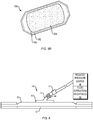
- FIG. 1 depicts an embodiment of an absorbent substrate 10, viewed from the bottom, showing a base layer 12 and a peripheral removable backing 14.
- the base layer 12 further includes a plurality of sites 16 for capturing skin grafts.
- the entire base layer 12 or just the sites 16 can be treated, e.g., coated with an adhesive, to make at least portions of the base layer surface tacky to promote capture of skin grafts.
- the base layer is also porous and in this illustrated embodiment a plurality of pores 18 are disposed between the graft capture sites 16.
- the pores 18 can be generally circular or elongated in one or more dimensions.
- the entire surface of the base layer can be porous or can include a network of lines or cross-shaped incisions or openings. Regardless of the shape or size of the pores 18, the porosity of the base layer 12 should be sufficient to permit fluid migration from a skin segment through the base layer 12 for absorption by the substrate 10.
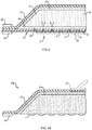
- FIG. 2 depicts the absorbent substrate 10 of FIG. 1 , viewed from the top, showing a sealing member 20 and a second peripheral removable backing 22 for handling purposes.
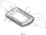
- FIG. 3 is a side view of the same absorbent substrate 10, showing the base layer 12, sealing member 20, and the first (bottom) and second (top) removable backings 14 and 22, respectively.
- FIG. 4 is a partial cross-sectional view of an absorbent substrate showing one embodiment of the internal structure.
- Base layer 16 and sealing member 20 define an enclosure for an absorbent material 24.
- the figure also schematically shows a plurality of micrografts 4 carried on a bottom surface (e.g., a skin-contacting surface) of the base layer 12.
- a plurality of pores 18 in the base layer permit fluid ingress and provide passageways to the absorbent material 24.
- one or more wicking layers can be utilized to distribute captured fluids to different portions of the absorbent material.
- a first wicking layer 26 is disposed in proximity to the base layer and a second wicking layer 28 is disposed in proximity to the sealing member 28.
- wicking material can form alternating layers with absorbent material layers (sandwich style) or wicking material can be distributed throughout or otherwise dispersed within the absorbent material.
- first and second wicking layers 26, 28, respectively can be joined together at the periphery to form a seal 30 that completely or substantially encloses the absorbent material.
- FIG. 4 shows the substrate 10 in use applied to a skin graft transplantation site on a surface of a patient's skin 2 in need of grafting.
- On the bottom surface of the base layer 12 are a plurality of captured skin grafts 4, which can be placed in contact with the skin 2 as the substrate 10 is applied. Fluid migration from the transplant site and extraction into the absorbent material 24 is illustrated by the dotted lines.
- FIG. 6 shows another embodiment of an absorbent substrate, having the base layer 12, sealing member 20 and a port 40 for coupling to a source of negative pressure 46 and/or a fluid extraction receptacle 48.
- the port 40 can further include a conduit 42, one or more filters 47 and/or a check valve 44 to permit fluid extraction (and, optionally, one-way flow) from the absorbent material, e.g., in instances where the absorbent material reaches or nears a saturated state to an external fluid receptacle or a waste disposal site.
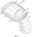
- FIG. 7 is a schematic view of a skin graft harvester 50 for use with an absorbent substrate in accordance with various aspects of the present teachings.
- the harvest 50 includes a detachable head portion 52 and harvester body 54.
- the harvester body 54 is adapted for placement on a patient's skin at a donor site where skin grafts are to be obtained, e.g., on the inner thigh, and secured in place, for example, with strap 56 (shown in phantom).
- the head 52 can further include a heater (not shown) powered via a coupler 60 adapted to couple with a power source in a base unit (not shown).
- the head 52 further includes a seal 63 which permits a reduced pressure chamber to be formed when the head 52 and body 54 are joined together and the harvester 50 is coupled to a vacuum pump or other source of reduced pressure, e.g., via coupler 60 connecting the harvester 50 to its base unit.
- the head 52 can further include one or more windows 58 for observation of skin blisters being formed within the chamber by application of reduced pressure, heat or both. Once the blisters have been formed, the head 52 can be removed, e.g., by deactivating the source of reduced pressure and by actuation of release levers 62, which break the seal 63 and allow the head 52 to be lifted off the harvester body 54.
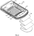
- FIG. 8 is a schematic view of the skin graft harvester 50 of FIG. 7 with the head 52 removed and the cutting mechanism 74 exposed.
- the harvester body 54 can include a base portion 70, a sled 72, and actuator handle 80.
- the cutting mechanism 74 can include a plurality of plates with initially aligned holes through which skin blisters are drawn by heat and/or application of suction when the head 52 is joined to the harvester body 54 and activated. Once the blisters are formed, they can be cleaved by the cutting mechanism 74. For example, below the top plate depicted in FIG. 8 , one or more additional plates, e.g., a cutter plate and a bottom plate can be deployed with aligned holes.
- the sled 72 By actuation (e.g., pulling up) of handle 80, the sled 72 is caused to move horizontally such that one of the plates below the top plate, e.g., the "cutter plate” (not shown) also moves (because of its linkage to the sled 72), thereby occluding the alignment of holes 78 and cleaving the raised blisters from the donor's skin.
- FIG. 9 is a schematic view of the skin graft harvester 50 of FIG. 7 with an absorbent substrate 10 according to the invention deployed in the harvester body 54 to capture skin grafts.
- the user e.g., clinician
- the base layer will also come into contact with the skin blisters.
- the substrate is so situated before the cutter mechanism is actuated to cleave the blisters into skin grafts (as described above).
- the substrate can be placed onto the harvester after cleavage to capture grafts that have already been cleaved from the skin. In either event the substrate can then be removed from the harvester body 54 and applied to a recipient site, as illustrated in FIG. 4 .
- the base layer 12 may have a periphery surrounding a central portion and a plurality of pores 18 disposed through the periphery and/or the central portion.
- the pores 18 in the base layer 12 may have any shape, such as, for example, circles, squares, stars, ovals, polygons, slits, complex curves, rectilinear shapes, triangles, or other shapes.
- the pores 18 may have a uniform pattern or may be randomly distributed on the base layer 12.
- Each pore 18 has a diameter. In certain embodiments, the average diameter of each of the pores 18 can be between about 6 mm to about 50 mm.
- the pores 18 may also be sized to enhance the Moisture Vapor Transfer Rate (MVTR) of the dressing 124, described further below.
- MVTR Moisture Vapor Transfer Rate
- the base layer can be fluid permeable, e.g., composed of a material that has high water permeability in either liquid or vapor form, such as polyurethanes, polyesters, polyvinyl chlorides, copolymers of vinyl chloride and vinyl acetate or vinyl chloride and ethylene, polyolefins, polyamides, polyethylene, polypropylene, silicone or polystyrenes, polyacrylics, polyacrylates, polyvinyl alcohol, and copolymers thereof.
- water permeable materials include polyurethane films, such as Ensure-IT dressing (Deseret Medical, Inc.) and POLYSKIN® transparent dressing (Kendall Company, Boston, Massachusetts).
- micro-sized or nano-sized voids e.g., voids having an average width ranging from about 0.1 nanometers to about 1 millimeter or from about 1 nanometer to about 100 micrometers.
- micro-pores having an average width of about 0.1 micrometers to about 1 millimeter can be desired.
- nano-pores having an average size of about 0.1 to about 100 nanometers, preferably about 1 to about 100 nanometers or about 1 to about 10 nanometers can be advantageous.
- a permeable or porous base layer can be formed from woven or non-woven (e.g., matted) fibers.
- the fibrous base layer can include microfibers and/or nanofibers.
- microfibers having an average diameter of about 0.1 to about 10 micrometers can be desired.
- the base layer can be a foamed material, such as an open cell polymer foam that is formed through the use of chemical and/or physical blowing agents during polymer processing.
- the foamed base layer should have a sufficiently open cell structure such that fluid passageways are formed through the full thickness of the foamed base layer to facilitate fluid extraction.
- the average width of the open cells can range from about 1 nanometer to about 1 millimeter, preferably in some instances from about 10 nanometer to about 100 micrometers, or from about 100 nanometers to 10 micrometers.
- Foam polymers can have from about 1 to 1000 pores per square inch, preferably in some instances, from about 10 to 100 pores per square inch.
- Preferred foam polymers can void fractions from about 10 to about 90 percent, or void fractions greater than 20 percent, 30 percent, 40 percent or 50 percent.
- porous as used herein is intended to encompass not only apertures or holes but also permeable and open cell foam structures as described above.
- the base layer 12 is preferably a soft material suitable for providing a fluid seal with the skin graft transplantation site as described herein.
- the base layer 12 may comprise a silicone gel, a soft silicone, hydrocolloid, hydrogel, polyurethane gel, polyolefin gel, hydrogenated styrenic copolymer gels, a foamed gel, a soft closed cell foam such as polyurethanes and polyolefins, polyurethane, polyolefin, or hydrogenated styrenic copolymers coated with an adhesive described below.
- the base layer 12 can have a thickness between about 500 microns ( ⁇ m) and about 1000 microns ( ⁇ m). In one embodiment, the base layer 12 has a stiffness between about 5 Shore OO and about 80 Shore OO.
- the base layer 12 can include hydrophobic or hydrophilic materials.
- the base layer 12 may be a hydrophobic-coated material.
- the base layer 12 may be formed by coating a mesh or porous material, such as, for example, woven, nonwoven, molded, or extruded mesh with a hydrophobic material.
- the hydrophobic material for the coating may be a soft silicone, for example.
- the adhesive 17 used to capture skin grafts and/or adhere the substrate 10 to a patient at the transplantation site may be any medically-acceptable adhesive.
- the adhesive 17 may comprise an acrylic adhesive, rubber adhesive, high-tack silicone adhesive, polyurethane, or other adhesive substance.
- the adhesive 17 may be a pressure-sensitive adhesive comprising an acrylic adhesive with a coating weight of 15 grams/m 2 (gsm) to 70 grams/m 2 (gsm).
- the adhesive 17 may be a continuous or a discontinuous layer of material. Discontinuities in the adhesive 17 may be provided by pores 18 in the base layer 12.
- the apertures in the adhesive may be formed after application of the adhesive to the base layer or by coating the adhesive 17 in patterns on the base layer.
- Factors that may be utilized to control the adhesion strength of the substrate 10 may include the diameter and number of the pores 18 in the base layer 12, the thickness of the base layer 12, the thickness and amount of the adhesive 17, and the tackiness of the adhesive 17.
- An increase in the amount of the adhesive 17 generally corresponds to an increase in the adhesion strength of the substrate 10.
- the size and configuration of the adhesive coated portions of the base layer 12, the thickness of the base layer 12, and the amount and tackiness of the adhesive utilized may be varied to provide a desired adhesion strength for the substrate 10.
- the thickness of the base layer 12 may be about 200 microns
- the adhesive layer 17 may have a thickness of about 30 microns and a tackiness of 2000 grams per 25 centimeter wide strip.
- the sealing member 20 has a periphery and a central portion.
- the periphery of the sealing member 20 may be positioned proximate the periphery of the base layer 12 such that the central portion of the sealing member 20 and the central portion of the base layer 12 define an enclosure.
- the sealing member 20 may cover the tissue site 6 to provide a fluid seal and a sealed space between the tissue site 6 and the sealing member 20 of the substrate 10. Further, the sealing member 20 may cover tissue, such as a portion of the epidermis 106, surrounding the tissue site 6 to provide the fluid seal.
- the sealing member 20 may be formed from any material that allows for a fluid seal.
- a fluid seal is a seal adequate to maintain reduced pressure at a desired site given the particular reduced pressure source or system involved.
- the sealing member 20 may comprise, for example, one or more of the following materials: hydrophilic polyurethane; cellulosics; hydrophilic polyamides; polyvinyl alcohol; polyvinyl pyrrolidone; hydrophilic acrylics; hydrophilic silicone elastomers; an INSPIRE 2301 material from Expopack Advanced Coatings of Wrexham, United Kingdom having, for example, an MVTR (inverted cup technique) of 14400 g/m 2 /24 hours and a thickness of about 30 microns; a thin, uncoated polymer drape; natural rubbers; polyisoprene; styrene butadiene rubber; chloroprene rubber; polybutadiene; nitrile rubber; butyl rubber; ethylene propylene rubber; ethylene propylene dien
- the sealing member 20 may allow vapor to exit while inhibiting liquids from exiting the sealed space provided by the substrate 10.
- the sealing member 20 may be a flexible, breathable film having a high MVTR of, for example, at least about 300g/m 2 per 24 hours.
- the sealing member 20 may comprise a range of medically suitable films having a thickness between about 15 microns ( ⁇ m) to about 50 microns ( ⁇ m). In other embodiments, a low or no vapor transfer drape can be used as the sealing member.
- the fluid management assembly may be disposed in the enclosure 31 and may include a first wicking layer 26, a second wicking layer 28, and an absorbent layer 24.
- the absorbent layer 24 may be positioned in fluid communication between the first wicking layer 26 and the second wicking layer 28.
- the first wicking layer 26 may have a grain structure (not shown) adapted to wick fluid along a surface of the first wicking layer 26.
- the second wicking layer 28 may have a grain structure (not shown) adapted to wick fluid along a surface of the second wicking layer 28.
- the first and the second wicking layer 26, 28 may wick or otherwise transport fluid in a lateral direction along the surfaces of the first and the second wicking layer 26, 28, respectively.
- the surfaces of the first and the second wicking layer 26, 28 may be normal relative to the thickness of each of the first and the second wicking layer 26, 28.
- the wicking of fluid along the first and the second wicking layers 26, 28 may enhance the distribution of the fluid over a surface area of the absorbent layer 24 that may increase absorbent efficiency and resist fluid blockages. Fluid blockages may be caused, for example, by fluid pooling in particular location in the absorbent layer 24 rather than being distributed more uniformly across the absorbent layer 24.
- the laminate combination of the first and the second wicking layer 26, 28 and the absorbent layer 24 may be adapted as described above to maintain an open structure, resistant to blockage, that can maintain fluid communication with, for example, the tissue site 6.
- the substrate 10 may include, without limitation, any number of wicking layers and absorbent layers as desired for treating a particular tissue site.
- the absorbent layer 24 may be a plurality of absorbent layers 24 positioned in fluid communication between the first wicking layer 26 and the second wicking layer 28 as described above.
- at least one intermediate wicking layer may be disposed in fluid communication between the plurality of absorbent layers 24. Similar to the absorbent layer 24 described above, the plurality of absorbent layers 24 and the at least one intermediate wicking layer may be positioned within the wicking layer enclosure.
- the absorbent material or layer 24 may be a hydrophilic material adapted to absorb fluid from, for example, the tissue site 6.
- Materials suitable for the absorbent layer 184 may include Luquafleece® material, Texus FP2326, BASF 402c, Technical Absorbents 2317 available from Technical Absorbents (www.techabsorbents.com), sodium polyacrylate super absorbers, cellulosics (carboxy methyl cellulose and salts such as sodium CMC), or alginates.
- Materials suitable for the first and second wicking layers 26, 28 may include any material having a grain structure capable of wicking fluid as described herein, such as, for example, Libeltex TDL2 80gsm.
- the substrate 10 can be a pre-laminated structure manufactured at a single location or simply individual layers of material stacked upon one another as described above. Individual layers of the substrate 10 may be bonded or otherwise secured to one another without adversely affecting fluid management by, for example, utilizing a solvent or non-solvent adhesive, or by thermal welding.
- the enclosure 31 defined by the base layer 12 and the sealing member 20 may include an anti-microbial layer.
- the addition of the anti-microbial agent may reduce the probability of excessive bacterial growth within the dressing 10 to permit the dressing 10 to remain in place for an extended period.
- the anti-microbial material may be, for example, an additional layer included as a part of the substrate 10 as depicted in FIGS. 1-4 , or a coating of an anti-microbial agent disposed in any suitable location within the substrate 10.
- the anti-microbial material may include elemental silver or similar compounds, for example.
- the base layer and absorbent material can be replaced by a single, unitary element (with or without wicking material) that provides both the skin-contacting and the fluid absorbing functions.
- FIGS. 5A and 5B illustrates such a substrate 10A including absorbent base 24A, an optional upper wicking layer and a sealing member 20.
- the substrate can further include a peripheral portion that does not have a foamed or sponge surface for securing the substrate to a patient's skin and/or a harvester for collection of skin grafts. As discussed above a backing can be disposed over this peripheral portion for handling purposes.
- the absorbent base can be a foamed polymer (e.g., a sponge) capable of attracting and absorbing fluids when placed in contact with the skin and optionally can further include a port 40 (shown in phantom) for coupling to a source of a source of reduced pressure as discussed above.
- a foamed polymer e.g., a sponge
- a port 40 shown in phantom
- the absorbent material having a skin-contacting surface in lieu of a separate base layer can be a sponge material, e.g., an elastic open pore structured polymer such as cellulose, collagen, gelatin/alginate, polyesters, polyethers, polyvinyl acetates, polyvinyl acetals, polyurethanes, gelatin/hyaluronates or chitosan/hyaluronates, polyvinyl alcohol, and polyacrylates.
- the sponge material can have a network of interconnected pores for fluid transport, the average cross-sectional width of which can range from 0.05 millimeters (mm) to about 5 millimeters (mm), more preferably from about 0.1 mm to about 1 mm in certain embodiments.
- FIG. 5B also shows another feature of the invention that can be used in any of the illustrated embodiments, namely a split lower backing.
- An inner portion of the backing 14A can be removed when the substrate is applied to the harvester to capture skin grafts.
- the surface beneath the backing 14A can include an adhesive for coupling to the harvester and a second portion of the backing 14B can remain in place until transplantation, at which time it can be removed exposing another portion of the surface (and optionally an adhesive) for contact with the skin.
- the function (or position) of backings 14A and 14B can, of course, be reversed.
- Various other arrangements can likewise be employed to permit securement of the substrate both at the time of harvesting and at transplantation.
- the port 40 for coupling to a source of reduced pressure can be positioned proximate to the sealing member 20 and in fluid communication with the absorbent material 24 through an aperture (not shown) in the sealing member 20 to provide reduced pressure from the reduced-pressure source 46 to the substrate 10.
- the port 40 may comprise a medical-grade, soft polymer or other pliable material.
- the port 40 may be formed from polyurethane, polyethylene, polyvinyl chloride (PVC), fluorosilicone, or ethylene-propylene, etc.
- port 40 may be molded from DEHP-free PVC.
- the port 40 may be formed in any suitable manner such as by molding, casting, machining, or extruding. Further, the port 40 may be formed as an integral unit or as individual components and may be coupled to the substrate 10 by, for example, adhesive, welding or mechanical coupling.
- the port 40 can also include one or more filters 47, e.g., an odor filter to inhibit the passage of odors from the tissue site 6 out of the sealed substrate 10, or a hydrophobic filter.
- the filter 47 can be disposed in the conduit 42 or other suitable location such that fluid communication between the reduced-pressure source 46 and the substrate is provided through the filter 47.
- the filters 47 can be positioned in any exit location in the substrate 10, such as an aperture (not shown), that is in fluid communication with the atmosphere or with the reduced-pressure source 46.
- the filter 47 may also be positioned in any suitable location in the substrate that is in fluid communication with the graft transplantation site 6.
- an odor filter 47 may include a carbon material in the form of a layer or particulate, such as a woven carbon cloth filter such as those manufactured by Chemviron Carbon, Ltd. of Lancashire, United Kingdom (www.chemvironcarbon.com).
- a hydrophobic filter 47 may be comprised of a material that is liquid impermeable and vapor permeable, such as a material manufactured under the designation MMT-314 by W.L. Gore & Associates, Inc. of Newark, Delaware, United States, or similar materials.
- the reduced-pressure source 46 provides reduced pressure to the substrate 10 and the sealed space 31.
- the reduced-pressure source 46 may be any suitable device for providing reduced pressure as described herein, such as, for example, a vacuum pump, wall suction, or other source. Additional details on reduced pressure sources can be found, for example, in U.S. Patent Application Ser. No. 11/646,918 filed December 28, 2006 , U.S. Patent Application Ser. No. 11/810,027 filed June 4, 2007 ; U.S. Patent Application Ser. No. 12/661,293 filed March 15, 2010 ; and U.S. Patent Application Ser. No. 13/052,873 filed March 21, 2011 . The disclosures of each of these patent applications are incorporated by reference in their entireties.
- reduced pressure generally refers to a pressure less than the ambient pressure at a tissue site being subjected to treatment. Typically, this reduced pressure will be less than the atmospheric pressure. The reduced pressure may also be less than a hydrostatic pressure at a tissue site. Unless otherwise indicated, values of pressure stated herein are gauge pressures. While the amount and nature of reduced pressure applied to a tissue site will typically vary according to the application, the reduced pressure will typically be between -5 mmHg and -500 mmHg, and more typically in a therapeutic range between -100 mmHg and -200 mmHg.
- the reduced pressure delivered may be constant or varied (e.g., patterned or random) and may be delivered continuously or intermittently.
- vacuum and "negative pressure” may be used to describe the pressure applied to the tissue site, the actual pressure applied to the tissue site may be more than the pressure normally associated with a complete vacuum.
- an increase in reduced pressure or vacuum pressure typically refers to a relative reduction in absolute pressure.
- An increase in reduced pressure corresponds to a reduction in pressure (more negative relative to ambient pressure) and a decrease in reduced pressure corresponds to an increase in pressure (less negative relative to ambient pressure).
- a conduit 42 having an internal lumen may be coupled in fluid communication between the reduced-pressure source 46 and the substrate 10.
- the conduit interface 43 may be coupled in fluid communication with the dressing and adapted to connect between the conduit 42 and the substrate 10 for providing fluid communication with the reduced-pressure source 46.
- the conduit interface 43 may be fluidly coupled to the conduit 42 in any suitable manner, such as, for example, by an adhesive, solvent or non-solvent bonding, welding, or interference fit.
- An aperture (not shown) in the sealing member 20 may provide fluid communication between the substrate and the conduit interface 43.
- the conduit 42 may be inserted into the substrate 10 through an aperture (not shown) in the sealing member 20 to provide fluid communication with the reduced-pressure source 46 without utilization of the conduit interface 43.
- the reduced-pressure source 46 may also be directly coupled in fluid communication with the substrate 10 and/or the sealing member 20.
- the conduit 42 may be, for example, a flexible polymer tube. A distal end of the conduit 42 may include any one of known couplings for attachment to the reduced-pressure source 46.
Abstract
Description
- This application claims priority to
U.S. Provisional Patent Application No. 61/860,822, filed July 31, 2013 U.S. Provisional Application No. 61/782,385, filed March 14, 2013 - The present invention relates generally to medical treatment systems and, more particularly, but not by way of limitation, to absorbent dressings, systems, and methods for harvesting and transplanting skin grafts.
- Skin is the largest organ of the human body, representing approximately 16% of a person's total body weight. Because it interfaces with the environment, skin has an important function in body defense, acting as an anatomical barrier from pathogens and other environmental substances. Skin also provides a semi-permeable barrier that prevents excessive fluid loss while ensuring that essential nutrients are not washed out of the body. Other functions of skin include insulation, temperature regulation, and sensation. Skin tissue may be subject to many forms of damage, including burns, trauma, disease, and depigmentation.
- Skin grafts are often used to repair such skin damage. Skin grafting is a surgical procedure in which a section of skin is removed from one area of a person's body (autograft), removed from another human source (allograft), or removed from another animal (xenograft), and transplanted to a recipient site of a patient, such as a wound site. As with any surgical procedure, skin grafting involves certain risks. Complications may include graft failure, rejection of the skin graft, bleeding, fluid accumulation or infection at either the donor or recipient site. Additionally, when an autograft is taken from one area of a person's body to produce the graft, some degree of trauma occurs at the donor site. If the recipient site is a large wound or otherwise damaged skin region, the trauma at the donor site can be significant.
- Techniques have been developed for harvesting a large number of smaller grafts, e.g., so-called micrografts, to reduce the trauma at the donor site. By removing only a fraction of the skin at a donor site and leaving regions of healthy skin surrounding the excised regions, a large amount of skin for transplantation can be obtained with less discomfort. Micrograft harvesting can also reduce the healing time and risk of infection.
- Harvesting of skin grafts can be accomplished in many different ways. One common technique for harvesting a skin graft involves the application of suction to separate a surface portion of the skin, e.g., the epidermis and a basal cell layer, from the underlying dermis. Harvesting of suction blisters typically also involves a heat source to facilitate blister formation.
- Various devices are available for generating and harvesting micrografts. For example, the Cellutome™ skin harvester is available from Kinetic Concepts, Inc. of San Antonio, Texas. The Cellutome™ system includes a head that provides a source of reduced pressure (vacuum), and optionally a heater element, and a harvester configured for placement on a target region of a patient's skin. The harvester is further adapted to form a sealing engagement with the head such that the target region of skin is embraced within an evacuated chamber. The Cellutome™ harvester further includes at least one alignment plate having a plurality of holes through which skin blisters can be raised in the presence of negative pressure; and a cutting plate having at least one cutting surface for cleaving skin blisters after they are formed within the chamber.
- Typically, micrograft harvesters rely upon a support or substrate to lift the excised blisters from the device. The substrate is then applied to a recipient site so that the plurality of micrografts can be assimilated as transplanted tissue. Ideally, the grafts will expand and coalesce to complete the healing process.
- Methods and devices for management of fluids during skin graft transplantation are disclosed. In one aspect of the invention, absorbent substrates for transplanting skin grafts are disclosed having a surface adapted to contact at least one excised skin graft and engage said graft for removal from a donor site; a sealing member at least partially surrounding an absorbent material disposed within the enclosure; wherein at least a portion of the skin-contacting surface is porous and in fluid communication with the absorbent layer to capture fluids.
- In one embodiment of the invention, absorbent substrates for transplanting skin grafts are disclosed including a base layer having a surface adapted to contact at least one excised skin graft and to engage said graft for removal from a donor site; a sealing member peripherally joined to the base layer and defining an enclosure therebetween; and an absorbent material disposed within the enclosure; wherein at least a portion of the base layer is porous and in fluid communication with the absorbent layer to capture fluids.
- In certain embodiments the substrate includes a base layer configured for positioning in a chamber of a skin graft harvesting device and, optionally, the base layer is further configured to capture a plurality of skin grafts at the same time.
- The base layer of the absorbent substrate preferably includes a biocompatible material, e.g., a material selected from the group of silicones, silicone gels, soft silicones, hydrocolloids, hydrogels, polyurethanes, polyurethane gels, polyolefins, polyolefin gels, hydrogenated styrenic copolymers, hydrogenated styrenic copolymer gels, foamed gels and combinations thereof. In some preferred embodiments, the base layer includes silicone.
- In certain embodiments, a skin graft contacting portion of the base layer has an average thickness between about 50 microns and about 10 millimeters, preferably in some cases, between about 500 microns (µm) and about 1000 microns (µm). The skin graft contacting portion of the base layer should also be flexible enough to conform to the shape of the harvester and/or the recipient site. For example, the skin graft contacting portion of the base layer can have a stiffness between about 5 Shore OO and about 80 Shore OO.
- In another aspect of the invention, the substrate further includes an adhesive associated with at least a part of the base layer to engage the graft. When used with multi-graft or "micrograft" harvesters, the substrate can further include a pattern of adhesive sites on a skin contacting surface of the base layer, each site arranged and configured to engage a corresponding skin graft raised by a skin graft harvesting device. For example, the substrate can carry a pattern of adhesive sites printed on at least a portion of a skin-contacting surface of the base layer. In certain embodiments, the adhesive can include an acrylic adhesive.
- In another aspect of the invention, the base layer can include a plurality of openings to provide passageways from fluid transport from the recipient site to the absorbent material. The openings (e.g., pores) can be spaced apart from each other. In certain embodiments, the openings are generally circular. The openings can have an average cross-sectional dimension ranging from about 0.1 nanometers to about 1 millimeter, or preferably an average cross-sectional dimension ranging from about 1 nanometer to about 100 micrometers. In other embodiments, the pores can be elongated or grid-like and their minor dimension can range from about 0.1 nanometers to about 1 millimeter, or preferably from about 1 nanometer to about 100 micrometers.
- In another aspect of the invention, the base layer is patterned to define a plurality of skin graft capture sites and the base layer further includes a network of pores disposed between at least some of the capture sites. Again, the pores (disposed between capture sites) can be circular or elongated and have an average cross-section dimension (or a minor dimension, in the case of elongated pores) ranging from about 0.1 nanometers to about 1 millimeter, or preferably ranging from about 1 nanometers to about 100 micrometers.
- In yet another aspect of the invention, the substrate can also include at least one wicking layer disposed in the enclosure and adapted to distribute fluid to the absorbent material. For example, the substrate can include at least a first wicking layer disposed in the enclosure between the base layer and the absorbent material. Alternatively, or in addition to the first wicking layer, the substrate can include one or more additional wicking layers (e.g., a second wicking layer) disposed in the enclosure between the absorbent material and the sealing member. In certain embodiments, the first and/or second wicking layer can have a grain structure adapted to wick fluid along a surface of the wicking layer.
- In certain embodiments, the absorbent material is a plurality of absorbent layers, and one or more of the additional absorbent layers are positioned in fluid communication between a first wicking layer and a second wicking layer. The substrate can also include at least one intermediate wicking layer disposed in fluid communication between the absorbent layers. In certain embodiments, a peripheral portion of a first wicking layer can be coupled to a peripheral portion of a second wicking layer to provide a wicking layer enclosure surrounding the absorbent layer between the first and the second wicking layers.
- In another aspect of the invention, the absorbent material can include a hydrophilic material that is adapted to absorb fluid and the sealing member is liquid impermeable. For example, the sealing member can include a water-impermeable polyurethane component.
- In an alternative embodiment, a unitary absorbent structure can be employed rather than a separate base layer and absorbent material. For example, an absorbent substrate according to this embodiment can include an absorbent material having a surface adapted to contact at least one excised skin graft and engage said graft for removal from a donor site. The absorbent material can further include a sealing member surrounding and defining an enclosure for the absorbent material and substantially sealing the absorbent material except for the skin contacting surface; and wherein at least a portion of skin contacting surface of the absorbent material is porous to capture fluids.
- In yet another aspect of the invention, the substrate can further include at least one port for coupling to the reduced pressure source to extract accumulated fluids from the substrate. The port can further include a valve, e.g., a check valve or one-way valve, to prevent backflow of extracted fluids. The port can further include a conduit providing fluid communication between the absorbent material or at least one wicking layer within the chamber and an external fluid receptacle.
- In another aspect, the substrate can include at least one removable backing for handling the substrate prior to positioning it in a skin graft harvester. The substrate can further include at least one removable backing for handling the substrate prior to positioning it at a recipient site. For example, the substrate can include at least a first removable backing associated with the base layer for handling the substrate prior to positioning it in a skin graft harvester and a second removable backing for handling the substrate and an associated skin graft prior to positioning it at a recipient site.
- In another embodiment, a skin graft transplantation substrate is provided including a base layer, an adhesive, a sealing member, a first wicking layer, a second wicking layer, an absorbent layer, and a conduit interface. The base layer has a periphery surrounding a central portion and a plurality of apertures disposed through the periphery and the central portion, wherein the base layer is adapted to cover the skin graft transplantation site and tissue surrounding the site. The sealing member has a periphery and a central portion, the periphery of the sealing member being positioned proximate the periphery of the base layer such that the central portion of the sealing member and the central portion of the base layer define an enclosure. The first wicking layer and the second wicking layer are each disposed in the enclosure. The absorbent layer is positioned in fluid communication between the first wicking layer and the second wicking layer. A peripheral portion of the first wicking layer is coupled to a peripheral portion of the second wicking layer providing a wicking layer enclosure surrounding the absorbent layer between the first and the second wicking layer. The conduit interface is positioned proximate to the sealing member and in fluid communication with the dressing.
- In another aspect, a system is provided for draining a skin transplantation site including a substrate or dressing and a reduced-pressure source. The substrate or dressing is adapted to provide reduced pressure and/or to store fluid extracted from the site. The substrate or dressing includes a base layer, an adhesive, a sealing member, a first wicking layer, a second wicking layer, an absorbent layer, and a conduit interface. The base layer has a periphery surrounding a central portion and a plurality of apertures disposed through the periphery and the central portion. The central portion of the base layer is adapted to be positioned proximate the transplantation site and the periphery of the base layer is adapted to be positioned proximate the tissue surrounding the transplantation site. Further, the periphery of the base layer is adapted to surround the transplantation site, and the apertures in the base layer are adapted to be in fluid communication with site and the tissue surrounding the transplantation site. In certain embodiments, adhesive can be stored or preloaded into apertures in the base layer such that upon placement of the base layer onto the transplantation site, the adhesive is released. (A two-part lower backing can also be employed such that a first (inner) portion of the lower backing is removed when the substrate is joined to a skin graft harvester and a second outer portion of the backing subsequently removed to facilitate peripheral adhesion at the transplantation site.) The sealing member has a periphery and a central portion, the periphery of the sealing member being positioned proximate the periphery of the base layer such that the central portion of the sealing member and the central portion of the base layer define an enclosure. The first wicking layer and the second wicking layer are each disposed in the enclosure. The absorbent layer is positioned in fluid communication between the first wicking layer and the second wicking layer. The conduit interface is positioned proximate to the sealing member and in fluid communication with the dressing. The reduced-pressure source is adapted to be coupled in fluid communication with the conduit interface to provide reduced pressure to the dressing.
- In another aspect of the invention, methods are disclosed for fluid management during skin transplantation. The methods can include the steps of contacting at least one skin graft with an absorbent substrate, the substrate comprising a base layer having a surface adapted to contact and engage at least one excised skin graft and a sealing member peripherally joined to the base layer and defining an enclosure therebetween; and an absorbent material disposed within the enclosure; deploying the substrate at a recipient site such that a skin graft that is engaged by the base layer contacts the recipient site; and maintaining the substrate in contact with the recipient site to facilitate transplantation of the graft and removal of fluids.
- In another aspect, the methods of the present invention can include maintaining the absorbent substrate at the recipient site, and further, removing excess fluids at the recipient site by extraction into the absorbent material of the substrate. The methods can be practiced by providing a plurality of pores in the base layer to provide a fluid communication path between a recipient site and the absorbent material within the substrate and, optionally, deploying at least one wicking layer within the substrate to distribute fluids captured from a recipient site to different regions of the absorbent material.
- In certain embodiments, the methods can further include a step of coupling the substrate to a reduced pressure source to facilitate fluid extraction and, optionally, draining accumulated fluids from the absorbent material into a fluid extraction receptacle or deploying a one-way valve between the absorbent material and the fluid extraction receptacle.
- Other aspects, features, and advantages of the illustrative embodiments will become apparent with reference to the drawings and detailed description that follow.
- A more complete understanding of this specification may be obtained by reference to the following detailed description when taken in conjunction with the accompanying drawings wherein:
-
FIG. 1 is a schematic, perspective bottom view of an illustrative embodiment of a absorbent substrate for management of fluids during skin graft transplantation; -
FIG. 2 is a schematic, perspective top view of the absorbent substrate ofFIG. 1 ; -
FIG. 3 is a schematic, side view of the absorbent substrate ofFIG. 1 ; -
FIG. 4 is a partial cross-sectional view of an absorbent substrate according to the invention; -
FIG. 5A is partial cross-sectional view of another absorbent substrate according to the invention in which the baser layer and absorbent material are a unitary structure. -
FIG. 5B is schematic perspective bottom view of the substrate ofFIG. 5A . -
FIG. 6 is a schematic, side view of an alternative embodiment of an absorbent substrate according to the invention having a port for coupling to a reduced pressure source or external fluid drainage receptacle; -
FIG. 7 is a schematic, perspective top view of a skin graft harvester for use with the absorbent substrate; -
FIG. 8 is a schematic, perspective top view of the skin graft harvester ofFIG. 6 with the head component removed and the cutter mechanism exposed; -
FIG. 9 is a schematic, perspective top view of the skin graft harvester ofFIG. 6 with an absorbent substrate according to the invention deployed in the harvester to capture skin grafts. - In the following detailed description of non-limiting, illustrative embodiments, reference is made to the accompanying drawings that form a part hereof. Other embodiments may be utilized and logical, structural, mechanical, electrical, and chemical changes may be made without departing from the scope of this specification. To avoid detail not necessary to enable those skilled in the art to practice the embodiments described herein, the description may omit certain information known to those skilled in the art. The following detailed description is not to be taken in a limiting sense, with the scope of the illustrative embodiments being defined by the appended claims.
- The term "micrograft" as used herein is intended to encompass skin grafts that have a width or length less than a millimeter, more preferably, less than 100 microns. A micrograft is an excised skin segment having at least one dimension parallel to the skin surface that is less than a millimeter, preferably less than 100 micrometers, more preferably in some applications less than 10 micrometers. The minimum width or length is preferably less than 500 micrometers, preferably less than 100 micrometers or less than 50 micrometers or less than 10 micrometers or less than 1 micrometer. For example, a micrograft can be generally circular, oval or oblong in a plane parallel to the skin surface and have a diameter or major axis that ranges from about 1 millimeter to 0.01 micrometers, or from about 100 micrometers to about 0.1 micrometers, or more preferably from about 50 to 1 micrometers. Micrografts also typically have a depth dimension that extends at least through the epidermis and preferably in some applications encompasses at least one layer of basal cells. The depth can range from about 500 micrometers to about 0.1 micrometers, preferably from about 100 micrometers to about 1 micrometer.
- The term "harvesting" as used herein is intended to encompass the removal of one or more skin grafts from an skin graft generating device, such as, for example, a suction blister micrograft generator, as well as the transplantation of such skin grafts and any intermediate steps, such as culturing, expanding, stretching, treating or otherwise preparing a skin graft for transfer to a recipient site.
- The terms "generally circular" and "circular" are used interchangeably herein to describe openings that are round, oval or otherwise form closed polygonal shapes having a major dimension (width or diameter) that is less than 5 times the minor dimension (width or diameter) of the shape. Preferably the major dimension is less than 3 times, or less than 2 times, the minor dimension.
- The term "about," as used herein, refers to variations in a numerical quantity that can occur, for example, through measuring or handling procedures in the real world; through inadvertent error in these procedures; through differences in the manufacture, source, or purity of compositions or reagents; and the like. Typically, the term "about" as used herein means greater or lesser than the value or range of values stated by 1/10 of the stated values, e.g., ±10%. For instance, a concentration value of about 30% can mean a concentration between 27% and 33%. The term "about" also refers to variations that would be recognized by one skilled in the art as being equivalent so long as such variations do not encompass known values practiced by the prior art. Each value or range of values preceded by the term "about" is also intended to encompass the embodiment of the stated absolute value or range of values. Whether or not modified by the term "about," quantitative values recited in the claims include equivalents to the recited values ,e.g., variations in the numerical quantity of such values that can occur, but would be recognized to be equivalents by a person skilled in the art.
- Referring to the drawings,
FIG. 1 depicts an embodiment of anabsorbent substrate 10, viewed from the bottom, showing abase layer 12 and a peripheralremovable backing 14. Thebase layer 12 further includes a plurality ofsites 16 for capturing skin grafts. Theentire base layer 12 or just thesites 16 can be treated, e.g., coated with an adhesive, to make at least portions of the base layer surface tacky to promote capture of skin grafts. The base layer is also porous and in this illustrated embodiment a plurality ofpores 18 are disposed between thegraft capture sites 16. Thepores 18 can be generally circular or elongated in one or more dimensions. Alternatively, the entire surface of the base layer can be porous or can include a network of lines or cross-shaped incisions or openings. Regardless of the shape or size of thepores 18, the porosity of thebase layer 12 should be sufficient to permit fluid migration from a skin segment through thebase layer 12 for absorption by thesubstrate 10. -
FIG. 2 depicts theabsorbent substrate 10 ofFIG. 1 , viewed from the top, showing a sealingmember 20 and a second peripheralremovable backing 22 for handling purposes.FIG. 3 is a side view of the sameabsorbent substrate 10, showing thebase layer 12, sealingmember 20, and the first (bottom) and second (top)removable backings -
FIG. 4 is a partial cross-sectional view of an absorbent substrate showing one embodiment of the internal structure.Base layer 16 and sealingmember 20 define an enclosure for anabsorbent material 24. The figure also schematically shows a plurality of micrografts 4 carried on a bottom surface (e.g., a skin-contacting surface) of thebase layer 12. A plurality ofpores 18 in the base layer permit fluid ingress and provide passageways to theabsorbent material 24. Optionally, one or more wicking layers can be utilized to distribute captured fluids to different portions of the absorbent material. In the illustrated embodiment, afirst wicking layer 26 is disposed in proximity to the base layer and asecond wicking layer 28 is disposed in proximity to the sealingmember 28. Alternatively, wicking material can form alternating layers with absorbent material layers (sandwich style) or wicking material can be distributed throughout or otherwise dispersed within the absorbent material. In the illustrated embodiment, the first and second wicking layers 26, 28, respectively, can be joined together at the periphery to form aseal 30 that completely or substantially encloses the absorbent material. - Additionally,
FIG. 4 shows thesubstrate 10 in use applied to a skin graft transplantation site on a surface of a patient'sskin 2 in need of grafting. On the bottom surface of thebase layer 12 are a plurality of captured skin grafts 4, which can be placed in contact with theskin 2 as thesubstrate 10 is applied. Fluid migration from the transplant site and extraction into theabsorbent material 24 is illustrated by the dotted lines. -
FIG. 6 shows another embodiment of an absorbent substrate, having thebase layer 12, sealingmember 20 and aport 40 for coupling to a source ofnegative pressure 46 and/or afluid extraction receptacle 48. Theport 40 can further include aconduit 42, one ormore filters 47 and/or acheck valve 44 to permit fluid extraction (and, optionally, one-way flow) from the absorbent material, e.g., in instances where the absorbent material reaches or nears a saturated state to an external fluid receptacle or a waste disposal site. -
FIG. 7 is a schematic view of askin graft harvester 50 for use with an absorbent substrate in accordance with various aspects of the present teachings. In this illustrative embodiment, theharvest 50 includes adetachable head portion 52 andharvester body 54. Theharvester body 54 is adapted for placement on a patient's skin at a donor site where skin grafts are to be obtained, e.g., on the inner thigh, and secured in place, for example, with strap 56 (shown in phantom). Thehead 52 can further include a heater (not shown) powered via acoupler 60 adapted to couple with a power source in a base unit (not shown). Thehead 52 further includes aseal 63 which permits a reduced pressure chamber to be formed when thehead 52 andbody 54 are joined together and theharvester 50 is coupled to a vacuum pump or other source of reduced pressure, e.g., viacoupler 60 connecting theharvester 50 to its base unit. Thehead 52 can further include one ormore windows 58 for observation of skin blisters being formed within the chamber by application of reduced pressure, heat or both. Once the blisters have been formed, thehead 52 can be removed, e.g., by deactivating the source of reduced pressure and by actuation of release levers 62, which break theseal 63 and allow thehead 52 to be lifted off theharvester body 54. - Additional details on harvesters useful in connection with the present invention can be found in
U.S. Patent Application No. 13/839,518 filed March 15, 2013 U.S. Patent Application No. 13/346,329 filed January 9, 2012 U.S. Patent Application No. 13/436,318 also filed January 9, 2012 U.S. Patent Application Ser. No. 13/014,737 filed January 27, 2011 ;U.S. Patent Application Ser. No. 12/851,656 filed August 6, 2010 U.S. Patent Application Ser. No. 12/851,621 filed August 6, 2010 U.S. Patent Application Ser. No. 12/851,703 filed August 6, 2010 U.S. Patent Application Ser. No. 12/851,682 filed August 6, 2010 -
FIG. 8 is a schematic view of theskin graft harvester 50 ofFIG. 7 with thehead 52 removed and thecutting mechanism 74 exposed. Theharvester body 54 can include abase portion 70, asled 72, and actuator handle 80. Thecutting mechanism 74 can include a plurality of plates with initially aligned holes through which skin blisters are drawn by heat and/or application of suction when thehead 52 is joined to theharvester body 54 and activated. Once the blisters are formed, they can be cleaved by thecutting mechanism 74. For example, below the top plate depicted inFIG. 8 , one or more additional plates, e.g., a cutter plate and a bottom plate can be deployed with aligned holes. By actuation (e.g., pulling up) ofhandle 80, thesled 72 is caused to move horizontally such that one of the plates below the top plate, e.g., the "cutter plate" (not shown) also moves (because of its linkage to the sled 72), thereby occluding the alignment ofholes 78 and cleaving the raised blisters from the donor's skin. -
FIG. 9 is a schematic view of theskin graft harvester 50 ofFIG. 7 with anabsorbent substrate 10 according to the invention deployed in theharvester body 54 to capture skin grafts. In the illustrated embodiment, the user (e.g., clinician) places thesubstrate 10 in the harvester holding thebacking 22 with the sealingmember 20 upwards and the base layer (not visible) in contact with the top plate of cutter mechanism (as shown inFIG. 8 ). By so placing the substrate, the base layer will also come into contact with the skin blisters. In one preferred embodiment, the substrate is so situated before the cutter mechanism is actuated to cleave the blisters into skin grafts (as described above). In other embodiments, the substrate can be placed onto the harvester after cleavage to capture grafts that have already been cleaved from the skin. In either event the substrate can then be removed from theharvester body 54 and applied to a recipient site, as illustrated inFIG. 4 . - Returning to
FIGS. 1-4 , thebase layer 12 may have a periphery surrounding a central portion and a plurality ofpores 18 disposed through the periphery and/or the central portion. Thepores 18 in thebase layer 12 may have any shape, such as, for example, circles, squares, stars, ovals, polygons, slits, complex curves, rectilinear shapes, triangles, or other shapes. Thepores 18 may have a uniform pattern or may be randomly distributed on thebase layer 12. Eachpore 18 has a diameter. In certain embodiments, the average diameter of each of thepores 18 can be between about 6 mm to about 50 mm. Thepores 18 may also be sized to enhance the Moisture Vapor Transfer Rate (MVTR) of the dressing 124, described further below. - Alternatively, the base layer can be fluid permeable, e.g., composed of a material that has high water permeability in either liquid or vapor form, such as polyurethanes, polyesters, polyvinyl chlorides, copolymers of vinyl chloride and vinyl acetate or vinyl chloride and ethylene, polyolefins, polyamides, polyethylene, polypropylene, silicone or polystyrenes, polyacrylics, polyacrylates, polyvinyl alcohol, and copolymers thereof. Examples of water permeable materials include polyurethane films, such as Ensure-IT dressing (Deseret Medical, Inc.) and POLYSKIN® transparent dressing (Kendall Company, Boston, Massachusetts).
- Various techniques can be employed to increase the permeability or porosity of polymer films, such as the incorporation of inclusions during polymer processing that are subsequently dissolved or evaporated away to leave micro-sized or nano-sized voids, e.g., voids having an average width ranging from about 0.1 nanometers to about 1 millimeter or from about 1 nanometer to about 100 micrometers. In certain embodiments, micro-pores having an average width of about 0.1 micrometers to about 1 millimeter can be desired. In other embodiments, nano-pores having an average size of about 0.1 to about 100 nanometers, preferably about 1 to about 100 nanometers or about 1 to about 10 nanometers, can be advantageous.
- In another embodiment, a permeable or porous base layer can be formed from woven or non-woven (e.g., matted) fibers. The fibrous base layer can include microfibers and/or nanofibers. In certain embodiments, microfibers having an average diameter of about 0.1 to about 10 micrometers can be desired. In other embodiments, nanofibers having an average diameter of about 1 to about 100 nanometers, preferably about 20 to about 80 nanometers, although in some instances, fibers with diameters about 1 to about 20 nanometers, can also be advantageous.
- In yet another embodiment, the base layer can be a foamed material, such as an open cell polymer foam that is formed through the use of chemical and/or physical blowing agents during polymer processing. The foamed base layer should have a sufficiently open cell structure such that fluid passageways are formed through the full thickness of the foamed base layer to facilitate fluid extraction. The average width of the open cells can range from about 1 nanometer to about 1 millimeter, preferably in some instances from about 10 nanometer to about 100 micrometers, or from about 100 nanometers to 10 micrometers. Foam polymers can have from about 1 to 1000 pores per square inch, preferably in some instances, from about 10 to 100 pores per square inch. Preferred foam polymers can void fractions from about 10 to about 90 percent, or void fractions greater than 20 percent, 30 percent, 40 percent or 50 percent.
- The terms "porous" as used herein is intended to encompass not only apertures or holes but also permeable and open cell foam structures as described above.
- The
base layer 12, in certain embodiments, is preferably a soft material suitable for providing a fluid seal with the skin graft transplantation site as described herein. For example, thebase layer 12 may comprise a silicone gel, a soft silicone, hydrocolloid, hydrogel, polyurethane gel, polyolefin gel, hydrogenated styrenic copolymer gels, a foamed gel, a soft closed cell foam such as polyurethanes and polyolefins, polyurethane, polyolefin, or hydrogenated styrenic copolymers coated with an adhesive described below. Thebase layer 12 can have a thickness between about 500 microns (µm) and about 1000 microns (µm). In one embodiment, thebase layer 12 has a stiffness between about 5 Shore OO and about 80 Shore OO. Thebase layer 12 can include hydrophobic or hydrophilic materials. - In some embodiments, the
base layer 12 may be a hydrophobic-coated material. For example, thebase layer 12 may be formed by coating a mesh or porous material, such as, for example, woven, nonwoven, molded, or extruded mesh with a hydrophobic material. The hydrophobic material for the coating may be a soft silicone, for example. - The adhesive 17 used to capture skin grafts and/or adhere the
substrate 10 to a patient at the transplantation site may be any medically-acceptable adhesive. For example, the adhesive 17 may comprise an acrylic adhesive, rubber adhesive, high-tack silicone adhesive, polyurethane, or other adhesive substance. In some embodiments, the adhesive 17 may be a pressure-sensitive adhesive comprising an acrylic adhesive with a coating weight of 15 grams/m2 (gsm) to 70 grams/m2 (gsm). The adhesive 17 may be a continuous or a discontinuous layer of material. Discontinuities in the adhesive 17 may be provided bypores 18 in thebase layer 12. The apertures in the adhesive may be formed after application of the adhesive to the base layer or by coating the adhesive 17 in patterns on the base layer. - Factors that may be utilized to control the adhesion strength of the
substrate 10 may include the diameter and number of thepores 18 in thebase layer 12, the thickness of thebase layer 12, the thickness and amount of the adhesive 17, and the tackiness of the adhesive 17. An increase in the amount of the adhesive 17 generally corresponds to an increase in the adhesion strength of thesubstrate 10. Thus, the size and configuration of the adhesive coated portions of thebase layer 12, the thickness of thebase layer 12, and the amount and tackiness of the adhesive utilized may be varied to provide a desired adhesion strength for thesubstrate 10. For example, the thickness of thebase layer 12 may be about 200 microns, and theadhesive layer 17 may have a thickness of about 30 microns and a tackiness of 2000 grams per 25 centimeter wide strip. - Continuing with
FIGS. 1-4 , the sealingmember 20 has a periphery and a central portion. The periphery of the sealingmember 20 may be positioned proximate the periphery of thebase layer 12 such that the central portion of the sealingmember 20 and the central portion of thebase layer 12 define an enclosure. - The sealing
member 20 may cover the tissue site 6 to provide a fluid seal and a sealed space between the tissue site 6 and the sealingmember 20 of thesubstrate 10. Further, the sealingmember 20 may cover tissue, such as a portion of the epidermis 106, surrounding the tissue site 6 to provide the fluid seal. - The sealing
member 20 may be formed from any material that allows for a fluid seal. A fluid seal is a seal adequate to maintain reduced pressure at a desired site given the particular reduced pressure source or system involved. The sealingmember 20 may comprise, for example, one or more of the following materials: hydrophilic polyurethane; cellulosics; hydrophilic polyamides; polyvinyl alcohol; polyvinyl pyrrolidone; hydrophilic acrylics; hydrophilic silicone elastomers; an INSPIRE 2301 material from Expopack Advanced Coatings of Wrexham, United Kingdom having, for example, an MVTR (inverted cup technique) of 14400 g/m2/24 hours and a thickness of about 30 microns; a thin, uncoated polymer drape; natural rubbers; polyisoprene; styrene butadiene rubber; chloroprene rubber; polybutadiene; nitrile rubber; butyl rubber; ethylene propylene rubber; ethylene propylene diene monomer; chlorosulfonated polyethylene; polysulfide rubber; polyurethane (PU); EVA film; co-polyester; silicones; a silicone drape; a 3M Tegaderm® drape; a polyurethane (PU) drape such as one available from Avery Dennison Corporation of Pasadena, California; polyether block polyamide copolymer (PEBAX), for example, from Arkema, France; or other appropriate material. - The sealing
member 20 may allow vapor to exit while inhibiting liquids from exiting the sealed space provided by thesubstrate 10. The sealingmember 20 may be a flexible, breathable film having a high MVTR of, for example, at least about 300g/m2 per 24 hours. The sealingmember 20 may comprise a range of medically suitable films having a thickness between about 15 microns (µm) to about 50 microns (µm). In other embodiments, a low or no vapor transfer drape can be used as the sealing member. - The fluid management assembly may be disposed in the
enclosure 31 and may include afirst wicking layer 26, asecond wicking layer 28, and anabsorbent layer 24. Theabsorbent layer 24 may be positioned in fluid communication between thefirst wicking layer 26 and thesecond wicking layer 28. Thefirst wicking layer 26 may have a grain structure (not shown) adapted to wick fluid along a surface of thefirst wicking layer 26. Similarly, thesecond wicking layer 28 may have a grain structure (not shown) adapted to wick fluid along a surface of thesecond wicking layer 28. For example, the first and thesecond wicking layer second wicking layer second wicking layer second wicking layer absorbent layer 24 that may increase absorbent efficiency and resist fluid blockages. Fluid blockages may be caused, for example, by fluid pooling in particular location in theabsorbent layer 24 rather than being distributed more uniformly across theabsorbent layer 24. The laminate combination of the first and thesecond wicking layer absorbent layer 24 may be adapted as described above to maintain an open structure, resistant to blockage, that can maintain fluid communication with, for example, the tissue site 6. - The
substrate 10 may include, without limitation, any number of wicking layers and absorbent layers as desired for treating a particular tissue site. For example, theabsorbent layer 24 may be a plurality ofabsorbent layers 24 positioned in fluid communication between thefirst wicking layer 26 and thesecond wicking layer 28 as described above. Further, at least one intermediate wicking layer may be disposed in fluid communication between the plurality ofabsorbent layers 24. Similar to theabsorbent layer 24 described above, the plurality ofabsorbent layers 24 and the at least one intermediate wicking layer may be positioned within the wicking layer enclosure. - In one embodiment, the absorbent material or
layer 24 may be a hydrophilic material adapted to absorb fluid from, for example, the tissue site 6. Materials suitable for the absorbent layer 184 may include Luquafleece® material, Texus FP2326, BASF 402c, Technical Absorbents 2317 available from Technical Absorbents (www.techabsorbents.com), sodium polyacrylate super absorbers, cellulosics (carboxy methyl cellulose and salts such as sodium CMC), or alginates. Materials suitable for the first and second wicking layers 26, 28 may include any material having a grain structure capable of wicking fluid as described herein, such as, for example, Libeltex TDL2 80gsm. - The
substrate 10 can be a pre-laminated structure manufactured at a single location or simply individual layers of material stacked upon one another as described above. Individual layers of thesubstrate 10 may be bonded or otherwise secured to one another without adversely affecting fluid management by, for example, utilizing a solvent or non-solvent adhesive, or by thermal welding. - In one embodiment, the
enclosure 31 defined by thebase layer 12 and the sealingmember 20 may include an anti-microbial layer. The addition of the anti-microbial agent may reduce the probability of excessive bacterial growth within the dressing 10 to permit the dressing 10 to remain in place for an extended period. The anti-microbial material may be, for example, an additional layer included as a part of thesubstrate 10 as depicted inFIGS. 1-4 , or a coating of an anti-microbial agent disposed in any suitable location within thesubstrate 10. The anti-microbial material may include elemental silver or similar compounds, for example. - In an alternative embodiment, the base layer and absorbent material can be replaced by a single, unitary element (with or without wicking material) that provides both the skin-contacting and the fluid absorbing functions.
FIGS. 5A and5B illustrates such a substrate 10A including absorbent base 24A, an optional upper wicking layer and a sealingmember 20. The substrate can further include a peripheral portion that does not have a foamed or sponge surface for securing the substrate to a patient's skin and/or a harvester for collection of skin grafts. As discussed above a backing can be disposed over this peripheral portion for handling purposes. The absorbent base can be a foamed polymer (e.g., a sponge) capable of attracting and absorbing fluids when placed in contact with the skin and optionally can further include a port 40 (shown in phantom) for coupling to a source of a source of reduced pressure as discussed above. - In this context the absorbent material having a skin-contacting surface in lieu of a separate base layer can be a sponge material, e.g., an elastic open pore structured polymer such as cellulose, collagen, gelatin/alginate, polyesters, polyethers, polyvinyl acetates, polyvinyl acetals, polyurethanes, gelatin/hyaluronates or chitosan/hyaluronates, polyvinyl alcohol, and polyacrylates. The sponge material can have a network of interconnected pores for fluid transport, the average cross-sectional width of which can range from 0.05 millimeters (mm) to about 5 millimeters (mm), more preferably from about 0.1 mm to about 1 mm in certain embodiments.
-
FIG. 5B also shows another feature of the invention that can be used in any of the illustrated embodiments, namely a split lower backing. An inner portion of the backing 14A can be removed when the substrate is applied to the harvester to capture skin grafts. The surface beneath the backing 14A can include an adhesive for coupling to the harvester and a second portion of the backing 14B can remain in place until transplantation, at which time it can be removed exposing another portion of the surface (and optionally an adhesive) for contact with the skin. The function (or position) of backings 14A and 14B can, of course, be reversed. Various other arrangements can likewise be employed to permit securement of the substrate both at the time of harvesting and at transplantation. - Referring now to
FIG. 6 , theport 40 for coupling to a source of reduced pressure can be positioned proximate to the sealingmember 20 and in fluid communication with theabsorbent material 24 through an aperture (not shown) in the sealingmember 20 to provide reduced pressure from the reduced-pressure source 46 to thesubstrate 10. Theport 40 may comprise a medical-grade, soft polymer or other pliable material. As non-limiting examples, theport 40 may be formed from polyurethane, polyethylene, polyvinyl chloride (PVC), fluorosilicone, or ethylene-propylene, etc. In one illustrative, non-limiting embodiment,port 40 may be molded from DEHP-free PVC. Theport 40 may be formed in any suitable manner such as by molding, casting, machining, or extruding. Further, theport 40 may be formed as an integral unit or as individual components and may be coupled to thesubstrate 10 by, for example, adhesive, welding or mechanical coupling. - The
port 40 can also include one ormore filters 47, e.g., an odor filter to inhibit the passage of odors from the tissue site 6 out of the sealedsubstrate 10, or a hydrophobic filter. Thefilter 47 can be disposed in theconduit 42 or other suitable location such that fluid communication between the reduced-pressure source 46 and the substrate is provided through thefilter 47. In another embodiment, thefilters 47 can be positioned in any exit location in thesubstrate 10, such as an aperture (not shown), that is in fluid communication with the atmosphere or with the reduced-pressure source 46. Thefilter 47 may also be positioned in any suitable location in the substrate that is in fluid communication with the graft transplantation site 6. - For example, an
odor filter 47 may include a carbon material in the form of a layer or particulate, such as a woven carbon cloth filter such as those manufactured by Chemviron Carbon, Ltd. of Lancashire, United Kingdom (www.chemvironcarbon.com). Ahydrophobic filter 47 may be comprised of a material that is liquid impermeable and vapor permeable, such as a material manufactured under the designation MMT-314 by W.L. Gore & Associates, Inc. of Newark, Delaware, United States, or similar materials. - Continuing with
FIG. 6 , the reduced-pressure source 46 provides reduced pressure to thesubstrate 10 and the sealedspace 31. The reduced-pressure source 46 may be any suitable device for providing reduced pressure as described herein, such as, for example, a vacuum pump, wall suction, or other source. Additional details on reduced pressure sources can be found, for example, inU.S. Patent Application Ser. No. 11/646,918 filed December 28, 2006 U.S. Patent Application Ser. No. 11/810,027 filed June 4, 2007 U.S. Patent Application Ser. No. 12/661,293 filed March 15, 2010 U.S. Patent Application Ser. No. 13/052,873 filed March 21, 2011 . The disclosures of each of these patent applications are incorporated by reference in their entireties. - As used herein, "reduced pressure" generally refers to a pressure less than the ambient pressure at a tissue site being subjected to treatment. Typically, this reduced pressure will be less than the atmospheric pressure. The reduced pressure may also be less than a hydrostatic pressure at a tissue site. Unless otherwise indicated, values of pressure stated herein are gauge pressures. While the amount and nature of reduced pressure applied to a tissue site will typically vary according to the application, the reduced pressure will typically be between -5 mmHg and -500 mmHg, and more typically in a therapeutic range between -100 mmHg and -200 mmHg.
- The reduced pressure delivered may be constant or varied (e.g., patterned or random) and may be delivered continuously or intermittently. Although the terms vacuum" and "negative pressure" may be used to describe the pressure applied to the tissue site, the actual pressure applied to the tissue site may be more than the pressure normally associated with a complete vacuum. Consistent with the use herein, an increase in reduced pressure or vacuum pressure typically refers to a relative reduction in absolute pressure. An increase in reduced pressure corresponds to a reduction in pressure (more negative relative to ambient pressure) and a decrease in reduced pressure corresponds to an increase in pressure (less negative relative to ambient pressure).
- A
conduit 42 having an internal lumen may be coupled in fluid communication between the reduced-pressure source 46 and thesubstrate 10. Theconduit interface 43 may be coupled in fluid communication with the dressing and adapted to connect between theconduit 42 and thesubstrate 10 for providing fluid communication with the reduced-pressure source 46. Theconduit interface 43 may be fluidly coupled to theconduit 42 in any suitable manner, such as, for example, by an adhesive, solvent or non-solvent bonding, welding, or interference fit. An aperture (not shown) in the sealingmember 20 may provide fluid communication between the substrate and theconduit interface 43. In one embodiment, theconduit 42 may be inserted into thesubstrate 10 through an aperture (not shown) in the sealingmember 20 to provide fluid communication with the reduced-pressure source 46 without utilization of theconduit interface 43. The reduced-pressure source 46 may also be directly coupled in fluid communication with thesubstrate 10 and/or the sealingmember 20. Theconduit 42 may be, for example, a flexible polymer tube. A distal end of theconduit 42 may include any one of known couplings for attachment to the reduced-pressure source 46. - Although this specification discloses advantages in the context of certain illustrative, non-limiting embodiments, various changes, substitutions, permutations, and alterations may be made without departing from the scope of the specification as defined by the appended claims. Further, any feature described in connection with any one embodiment may also be applicable to any other embodiment.
- Aspects of the invention are disclosed in the following numbered clauses:
- 1. An absorbent substrate for transplanting a skin graft, comprising
a base layer having a surface adapted to contact at least one excised skin graft and engage said graft for removal from a donor site;
a sealing member peripherally joined to the base layer and defining an enclosure therebetween; and
an absorbent material disposed within the enclosure;
wherein at least a portion of the base layer is porous and in fluid communication with the absorbent layer to capture fluids. - 2. The substrate of clause 1 wherein the base layer is configured to be positioned in a chamber of a skin graft harvesting device.
- 3. The substrate of
clause 2 wherein the base layer is configured to capture a plurality of skin grafts at the same time. - 4. The substrate of clause 1 wherein the base layer comprises a biocompatible material.
- 5. The substrate of clause 1 wherein the biocompatible material is selected from the group of silicones, silicone gels, soft silicones, hydrocolloids, hydrogels, polyurethanes, polyurethane gels, polyolefins, polyolefin gels, hydrogenated styrenic copolymers, hydrogenated styrenic copolymer gels, foamed gels and combinations thereof.
- 6. The substrate of clause 1 wherein the base layer comprises a silicone.
- 7. The substrate of clause 1 wherein a skin graft contacting portion of the base layer has an average thickness between about 500 microns (µη) and about 1000 microns (µ
 η).
η).
- 8. The substrate of clause 1 wherein a skin graft contacting portion of the base layer has a stiffness between about 5 Shore OO and about 80 Shore OO.
- 9. The substrate of clause 1 wherein the substrate further comprises an adhesive associated with at least a part of the base layer.
- 10. The substrate of clause 9 wherein the substrate further comprises a pattern of adhesive sites on a skin contacting surface of the base layer, each site arranged and configured to engage a corresponding skin graft raised by a skin graft harvesting device.
- 11. The substrate of clause 1 wherein the substrate further comprises a pattern of adhesive sites printed on at least a portion of a skin-contacting surface of the base layer.
- 12. The substrate of clause 9 wherein the adhesive comprises an acrylic adhesive.
- 13. The substrate of clause 1 wherein the porous base layer further comprises a plurality of pores to provide passageways from fluid transport from the recipient site to the absorbent material.
- 14. The substrate of clause 13 wherein the base layer comprises foamed polymer.
- 15. The substrate of clause 13 wherein the base layer comprises a fluid permeable polymeric material.
- 16. The substrate of clause 13 wherein the base layer comprises a fibrous material.
- 17. The substrate of
clause 16 wherein the fibrous material comprises a plurality of microfibers having an average diameter of about 0.1 to about 10 micrometers. - 18. The substrate of
clause 16 wherein the fibrous material comprises a plurality of nano fibers having an average diameter of about 1 to about 100 nanometers. - 19. The substrate of
clause 16 wherein the fibrous material comprises a plurality of nanofibers having an average diameter of about 20 to about 80 nanometers. - 20. The substrate of clause 13 wherein the pores have an average cross-section dimension ranging from about 1 nanometers to about 1 millimeter.
- 21. The substrate of clause 13 wherein the pores have an average cross-section dimension ranging from about 1 nanometer to about 100 micrometers.
- 22. The substrate of clause 3 wherein the base layer is patterned to define a plurality of skin graft capture sites and wherein the base layer further comprises a network of pores disposed between at least some of the capture sites.
- 23. The substrate of
clause 22 wherein the pores are generally circular and have an average cross-section dimension ranging from about 1 nanometers to about 1 millimeter. - 24. The substrate of clause 23 wherein the openings have average cross-section dimension ranging from about 1 nanometers to about 100 micrometer.
- 25. The substrate of clause 1 wherein the substrate further comprises at least one wicking layer disposed in the enclosure and adapted to distribute fluid to the absorbent material.
- 26. The substrate of clause 1 wherein the substrate further comprises at least a first wicking layer disposed in the enclosure between the base layer and the absorbent material.
- 27. The substrate of
clause 26 wherein the substrate further comprises at least a second wicking layer disposed in the enclosure between the absorbent material and the sealing member. - 28. The substrate of clause 27 wherein the first wicking layer has a grain structure adapted to wick fluid along a surface of the first wicking layer, and wherein the second wicking layer has a grain structure adapted to wick fluid along a surface of the second wicking layer.
- 29. The substrate of
clause 28 wherein the absorbent material comprises a plurality of absorbent layers, and wherein the plurality of absorbent layers are positioned in fluid communication between the first wicking layer and the second wicking layer. - 30. The substrate of clause 29 further comprising at least one intermediate wicking layer disposed in fluid communication between the absorbent layers.
- 31. The substrate of clause 27 wherein a peripheral portion of the first wicking layer is coupled to a peripheral portion of the second wicking layer providing a wicking layer enclosure surrounding the absorbent layer between the first and the second wicking layer.
- 32. The substrate of clause 1 wherein the absorbent material is comprised of a hydrophilic material that is adapted to absorb fluid.
- 33. The substrate of clause 1 wherein the sealing member is liquid impermeable.
- 34. The substrate of clause 1 wherein the sealing member comprises polyurethane.
- 35. The substrate of clause 1 further comprising at least one a port for coupling to the reduced pressure source to extract accumulated fluids from the substrate.
- 36. The substrate of clause 35 wherein the port further comprises a valve.
- 37. The substrate of clause 35 wherein the port further comprises a conduit providing fluid communication between the absorbent material or at least one wicking layer within the chamber to an external fluid receptacle.
- 38. The substrate of clause 1 wherein the substrate comprises at least one removable backing for handling the substrate prior to positioning in a skin graft harvester.
- 39. The substrate of clause 1 wherein the substrate comprises at least one removable backing for handling the substrate prior to positioning at a recipient site.
- 40. The substrate of clause 1 wherein the substrate comprises at least a first removable backing associated with the base layer for handling the substrate prior to positioning in a skin graft harvester and a second removable backing for handling the substrate and an associated skin graft prior to positioning at a recipient site.
- 41. The substrate of clause 1 wherein the base layer and the absorbent material are formed as a unitary structure.
- 42. An absorbent substrate for transplanting a skin graft, comprising
an absorbent material having a surface adapted to contact at least one excised skin graft and engage said graft for removal from a donor site;
a sealing member surrounding and defining an enclosure for the absorbent material and substantially sealing the absorbent material except for the skin contacting surface; and
wherein at least a portion of skin contacting surface of the absorbent material is porous to capture fluids. - 43. The substrate of
clause 42 wherein the skin contacting surface of the absorbent material is configured to be positioned in a chamber of a skin graft harvesting device. - 44. The substrate of
clause 42 wherein the absorbent material comprises an open cell foamed polymer. - 45. The substrate of
clause 42 wherein the absorbent material comprises a sponge material. - 46. The substrate of
clause 42 wherein the absorbent material is selected from the group of silicones, silicone gels, soft silicones, hydrocolloids, hydrogels, polyurethanes, polyurethane gels, polyolefins, polyolefin gels, hydrogenated styrenic copolymers, hydrogenated styrenic copolymer gels, foamed gels and combinations thereof. - 47. The substrate of
clause 42 wherein the substrate further comprises an adhesive associated with at least a part of the skin-contacting surface. - 48. The substrate of
clause 42 wherein the substrate further comprises a pattern of adhesive sites printed on at least a portion of a skin-contacting surface. - 49. The substrate of
clause 47 wherein the adhesive comprises an acrylic adhesive. - 50. The substrate of
clause 42 wherein the absorbent material has pores with an average cross-section dimension ranging from about 0.05 millimeters to about 5 millimeters. - 51. The substrate of
clause 42 wherein the absorbent material has pores with an average cross-section dimension ranging from about 0.1 millimeters to about 1 millimeters. - 52. The substrate of
clause 42 wherein the substrate further comprises at least one wicking layer disposed in the enclosure and adapted to distribute fluid to the absorbent material. - 53. The substrate of
clause 42 wherein the substrate further comprises at least a first wicking layer disposed in the enclosure. - 54. The substrate of clause 53 wherein the wicking layer is disposed in the enclosure between the absorbent material and the sealing member.
- 55. The substrate of
clause 42 wherein the absorbent material comprises a plurality of absorbent layers. - 56. The substrate of clause 55 further comprising at least one intermediate wicking layer disposed in fluid communication between the absorbent layers.
- 57. The substrate of
clause 42 wherein the absorbent material comprises a hydrophilic material that is adapted to absorb fluid. - 58. The substrate of
clause 42 wherein the absorbent material comprises at least one absorbent material selected from the group of silicones, silicone gels, soft silicones, hydrocolloids, hydrogels, polyurethanes, polyurethane gels, polyolefins, polyolefin gels, hydrogenated styrenic copolymers, hydrogenated styrenic copolymer gels, foamed gels and combinations thereof. - 59. The substrate of
clause 42 wherein the absorbent material comprises at least one absorbent material selected from the group of polyurethanes, polyesters, polyolefins, polyamides, polyethylenes, polypropylenes, polyvinyl chlorides, copolymers of vinyl chloride and vinyl acetate, copolymers of vinyl chloride and ethylene, silicone, polystyrenes, polyvinyl alcohol, polyacrylics, and polyacrylates. - 60. The substrate of
clause 42 wherein the absorbent material comprises at least one sponge material. - 61. The substrate of
clause 42 wherein the sponge material further comprises an elastic open pore structured polymer such as cellulose, collagen, gelatin/alginate, polyesters, polyethers, polyvinyl acetates, polyurethanes, gelatin/hyaluronate, chitosan/hyaluronate, polyvinyl alcohol, polyacrylics or polyacrylates. - 62. The substrate of
clause 42 wherein the sealing member is liquid impermeable. - 63. The substrate of
clause 42 wherein the sealing member comprises polyurethane. - 64. The substrate of
clause 42 further comprising at least one a port for coupling to the reduced pressure source to extract accumulated fluids from the substrate. - 65. The substrate of clause 64 wherein the port further comprises a valve.
- 66. The substrate of clause 64 wherein the port further comprises a conduit providing fluid communication between the absorbent material or at least one wicking layer within the chamber to an external fluid receptacle.
- 67. The substrate of
clause 42 wherein the substrate comprises at least one removable backing for handling the substrate prior to positioning in a skin graft harvester. - 68. The substrate of
clause 42 wherein the substrate comprises at least one removable backing for handling the substrate prior to positioning at a recipient site. - 69. The substrate of
clause 42 wherein the substrate comprises at least a first removable backing associated with the base layer for handling the substrate prior to positioning in a skin graft harvester and a second removable backing for handling the substrate and an associated skin graft prior to positioning at a recipient site. - 70. A system for harvesting and transporting skin grafts comprising
a harvester configured for placement at a donor site of a patient's skin and further adapted for coupling to a source of reduced pressure such that the donor site of skin is embraced within an evacuated chamber, the harvester further comprising a cutter mechanism for excising skin grafts that raised by the source of reduced pressure within the chamber; and
an absorbent substrate having a surface adapted to couple with the cutter mechanism to contact at least one excised skin graft and engage said graft for removal from the harvester; and
wherein at least a portion of skin contacting surface of the absorbent substrate is porous to capture fluids. - 71. The system of
clause 70 wherein the substrate further comprises an absorbent material in fluid communication with the skin contacting surface. - 72. The system of clause 71 wherein the absorbent material includes a skin contacting surface.
- 73. The system of
clause 70 wherein at least a portion of skin contacting surface of the absorbent material is porous to capture fluids. - 74. The system of
clause 70 wherein the system further comprises a base layer that provides a skin contacting surface. - 75. The system of
clause 74 wherein at least a portion of skin contacting surface of the base layer is porous to capture fluids. - 76. The system of clause 71 wherein the system further comprises a sealing member surrounding and defining an enclosure for the absorbent material.
- 77. The system of
clause 70 wherein the cutter mechanism of the harvester further comprises at least one alignment plate having a plurality of holes through which skin blisters can be raised in the presence of negative pressure. - 78. The system of clause 77 wherein the cutter mechanism further comprises a cutting plate having at least one cutting surface for cleaving skin blisters after they are formed within the chamber.
- 79. The system according to clause 77 wherein said at least one alignment plate comprises a top alignment plate and a bottom alignment plate and wherein a cutting plate is disposed therebetween.
- 80. The system according to clause 79 wherein the top plate, bottom plate and cutting plate each have a plurality of holes that are adapted to be concentrically aligned to facilitate blister formation.
- 81. The system of
clause 80 wherein the absorbent substrate is adapted for disposition on the top plate. - 82. A method for fluid management during skin transplantation comprising:
- contacting at least one skin graft with an absorbent substrate, the substrate comprising a base layer having a surface adapted to contact and engage at least one excised skin graft and a sealing member peripherally joined to the base layer and defining an enclosure therebetween, and an absorbent material disposed within the enclosure;
- deploying the substrate at a recipient site such that a skin graft that is engaged by the base layer contacts a recipient site; and
- maintaining the substrate in contact with the recipient site to facilitate transplantation of the graft and removal of fluids.
- 83. The method of clause 82 wherein the method further comprises providing a plurality of pores in the base layer to provide a fluid communication path between a recipient site and the absorbent material within the substrate.
- 84. The method of clause 83 further comprising deploying at least one wicking layer within the substrate to distribute fluids captured from a recipient site to different regions of the absorbent material.
- 85. The method of clause 82 wherein the method further comprises maintaining the absorbent substrate at the recipient site and removing excess fluids at the recipient site by extraction into the absorbent material of the substrate.
- 86. The method of clause 82 wherein the method further comprises coupling the substrate to a reduced pressure source to facilitate fluid extraction.
- 87. The method of clause 83 wherein the method further comprises draining accumulated fluids from the absorbent material into a fluid extraction receptacle.
- 88. The method of clause 87 wherein the method further comprises deploying a one-way valve between the absorbent material and the fluid extraction receptacle.
Claims (9)
- An absorbent substrate for transplanting a skin graft, comprising:a base layer (12), at least a portion of which is porous, having at least one adhesive site (16) for contacting at least one excised skin graft and capturing said graft for removal from a donor site;a sealing membrane (20) peripherally joined to the base layer (12) and defining an enclosure therebetween; andan absorbent material (24) disposed within the enclosure;wherein the substrate further comprises a wicking layer (26) disposed in the enclosure between the base layer (12) and the absorbent material (24) for distributing fluid to the absorbent material.
- The substrate of claim 1, wherein the base layer (12) comprises a biocompatible material.
- The substrate of claim 2, wherein the biocompatible material is selected from the groups of silicones, silicone gels, soft silicones, hydrocolloids, hydrogels, polyurethanes, polyurethane gels, polyolefins, polyolefin gels, hydrogenated styrenic copolymers, hydrogenated styrenic copolymer gels, foamed gels and combinations thereof.
- The substrate of any one of claims 1-3 wherein the at least one adhesive site (16) of the base layer (12) has an average thickness between about 500 microns (µm) and about 1000 microns (µm).
- The substrate of any one of claims 1-4, wherein the substrate further comprises a pattern of adhesive sites on a skin-contacting surface of the base layer, each site for engaging a corresponding skin graft raised by a skin graft harvesting device.
- The substrate of claim 1, wherein the base layer (12) further comprises a plurality of pores (18) to provide passageways for fluid transport from a recipient site to the absorbent material (24), and wherein the base layer (12) further comprises a foamed polymer, a fluid permeable polymeric material, or a fibrous material.
- The substrate of claim 7, wherein said at least one adhesive site comprises a pattern of capture sites (16) and said base layer (12) further comprises a network of pores (18) disposed between at least some of said capture sites.
- The substrate of claim 7, wherein said pores (18) are circular and have an average cross-sectional dimension ranging from about 1 nanometer to about 1 millimeter.
- The substrate of claim 1, wherein said wicking layer (26) has a grain structure adapted to wick fluid along a lateral direction thereof.
Applications Claiming Priority (3)
| Application Number | Priority Date | Filing Date | Title |
|---|---|---|---|
| US201361782385P | 2013-03-14 | 2013-03-14 | |
| US201361860822P | 2013-07-31 | 2013-07-31 | |
| EP14769345.1A EP2967627B1 (en) | 2013-03-14 | 2014-03-14 | Absorbent substrates for harvesting skin grafts |
Related Parent Applications (1)
| Application Number | Title | Priority Date | Filing Date |
|---|---|---|---|
| EP14769345.1A Division EP2967627B1 (en) | 2013-03-14 | 2014-03-14 | Absorbent substrates for harvesting skin grafts |
Publications (1)
| Publication Number | Publication Date |
|---|---|
| EP3289988A1 true EP3289988A1 (en) | 2018-03-07 |
Family
ID=51531295
Family Applications (2)
| Application Number | Title | Priority Date | Filing Date |
|---|---|---|---|
| EP17186324.4A Withdrawn EP3289988A1 (en) | 2013-03-14 | 2014-03-14 | Absorbent substrates for harvesting skin grafts |
| EP14769345.1A Active EP2967627B1 (en) | 2013-03-14 | 2014-03-14 | Absorbent substrates for harvesting skin grafts |
Family Applications After (1)
| Application Number | Title | Priority Date | Filing Date |
|---|---|---|---|
| EP14769345.1A Active EP2967627B1 (en) | 2013-03-14 | 2014-03-14 | Absorbent substrates for harvesting skin grafts |
Country Status (7)
| Country | Link |
|---|---|
| US (2) | US9962254B2 (en) |
| EP (2) | EP3289988A1 (en) |
| JP (2) | JP6491188B2 (en) |
| CN (1) | CN105636532B (en) |
| AU (1) | AU2014239952B2 (en) |
| CA (1) | CA2905481C (en) |
| WO (1) | WO2014152319A2 (en) |
Families Citing this family (38)
| Publication number | Priority date | Publication date | Assignee | Title |
|---|---|---|---|---|
| KR101642821B1 (en) | 2008-09-24 | 2016-07-26 | 더 제너럴 하스피탈 코포레이션 | Method and apparatus for grafting of skin tissue |
| US9610093B2 (en) | 2010-08-06 | 2017-04-04 | Kci Licensing, Inc. | Microblister skin grafting |
| US9597111B2 (en) | 2010-08-06 | 2017-03-21 | Kci Licensing, Inc. | Methods for applying a skin graft |
| US8978234B2 (en) | 2011-12-07 | 2015-03-17 | MoMelan Technologies, Inc. | Methods of manufacturing devices for generating skin grafts |
| US9168179B2 (en) * | 2011-06-24 | 2015-10-27 | Kci Licensing, Inc. | Reduced-pressure dressings employing tissue-fixation elements |
| AU2014239952B2 (en) | 2013-03-14 | 2018-09-27 | Solventum Intellectual Properties Company | Absorbent substrates for harvesting skin grafts |
| US9180001B2 (en) * | 2013-08-16 | 2015-11-10 | C.R. Bard, Inc. | Methods of breast surgery |
| WO2015103043A1 (en) | 2013-12-31 | 2015-07-09 | Kci Licensing, Inc. | Sensor systems for skin graft harvesting |
| CN106028982B (en) | 2013-12-31 | 2020-06-12 | 凯希特许有限公司 | Fluid assisted skin graft harvesting |
| EP3280465B1 (en) | 2015-04-09 | 2020-12-16 | 3M Innovative Properties Company | Soft-tack, porous substrates for harvesting skin grafts |
| GB2537841B (en) * | 2015-04-27 | 2020-12-09 | Medtrade Products Ltd | Wound dressing |
| CN113367890B (en) | 2015-04-27 | 2023-02-21 | 史密夫及内修公开有限公司 | Pressure reducing device |
| US11006974B2 (en) * | 2015-11-03 | 2021-05-18 | Kci Licensing, Inc. | Devices for creating an epidermal graft sheet |
| JP7044705B2 (en) | 2015-12-30 | 2022-03-30 | スミス アンド ネフュー ピーエルシー | Negative pressure wound healing device |
| SE541418C2 (en) | 2016-01-22 | 2019-09-24 | S2Medical Ab | Minimally invasive tissue harvesting device |
| EP3426206B1 (en) | 2016-03-07 | 2023-05-10 | Smith & Nephew plc | Wound treatment apparatuses and methods with negative pressure source integrated into wound dressing |
| DE102016106097B3 (en) * | 2016-04-04 | 2017-05-18 | Leibniz-Institut Für Polymerforschung Dresden E.V. | Tissue and organ transport device |
| SG11201809178XA (en) | 2016-04-26 | 2018-11-29 | Smith & Nephew | Wound dressings and methods of use with integrated negative pressure source having a fluid ingress inhibition component |
| US11096831B2 (en) | 2016-05-03 | 2021-08-24 | Smith & Nephew Plc | Negative pressure wound therapy device activation and control |
| CN109069710B (en) | 2016-05-03 | 2022-04-12 | 史密夫及内修公开有限公司 | Optimizing power delivery to a negative pressure source in a negative pressure therapy system |
| EP3452131A1 (en) | 2016-05-03 | 2019-03-13 | Smith & Nephew PLC | Systems and methods for driving negative pressure sources in negative pressure therapy systems |
| EP3503857B1 (en) | 2016-08-25 | 2024-04-17 | Smith & Nephew plc | Absorbent negative pressure wound therapy dressing |
| US11564847B2 (en) | 2016-09-30 | 2023-01-31 | Smith & Nephew Plc | Negative pressure wound treatment apparatuses and methods with integrated electronics |
| AU2018229808B2 (en) | 2017-03-08 | 2024-04-11 | Smith & Nephew Plc | Negative pressure wound therapy device control in presence of fault condition |
| DE102017106310B4 (en) | 2017-03-23 | 2018-10-11 | Lavenir Bioscience Ag | Apparatus and method for producing a micrograft matrix from full skin |
| AU2018265052B2 (en) | 2017-05-09 | 2023-08-31 | Smith & Nephew Plc | Redundant controls for negative pressure wound therapy systems |
| EP3634513B1 (en) * | 2017-05-12 | 2021-06-30 | KCI USA, Inc. | Adherent, bioresorbable transplant substrate |
| CN107496053A (en) * | 2017-08-11 | 2017-12-22 | 京东方科技集团股份有限公司 | Electronic skin, preparation method and driving method |
| US10559742B1 (en) * | 2017-08-24 | 2020-02-11 | Mainstream Engineering Corporation | Mounting pad and method for deterring theft and securing air conditioning units against high winds |
| WO2019053101A1 (en) | 2017-09-13 | 2019-03-21 | Smith & Nephew Plc | Negative pressure wound treatment apparatuses and methods with integrated electronics |
| GB201718070D0 (en) | 2017-11-01 | 2017-12-13 | Smith & Nephew | Negative pressure wound treatment apparatuses and methods with integrated electronics |
| GB201718054D0 (en) | 2017-11-01 | 2017-12-13 | Smith & Nephew | Sterilization of integrated negative pressure wound treatment apparatuses and sterilization methods |
| GB201718072D0 (en) | 2017-11-01 | 2017-12-13 | Smith & Nephew | Negative pressure wound treatment apparatuses and methods with integrated electronics |
| WO2019086332A1 (en) | 2017-11-01 | 2019-05-09 | Smith & Nephew Plc | Negative pressure wound treatment apparatuses and methods with integrated electronics |
| WO2019108738A1 (en) * | 2017-11-29 | 2019-06-06 | Kci Licensing, Inc. | Nanomodified transfer drape for epidermal grafting |
| USD898925S1 (en) | 2018-09-13 | 2020-10-13 | Smith & Nephew Plc | Medical dressing |
| EP3721822A1 (en) * | 2019-04-11 | 2020-10-14 | ETH Zurich | Device for taking essentially two-dimensional plane material sections, tensioning device, system for tensioning |
| US20220015950A1 (en) * | 2020-07-15 | 2022-01-20 | Joseph Smith | Bandage with removable cap |
Citations (2)
| Publication number | Priority date | Publication date | Assignee | Title |
|---|---|---|---|---|
| WO2003068120A1 (en) * | 2002-01-18 | 2003-08-21 | Levin John M | Force-transmission-control system and devices employing same |
| US20110282309A1 (en) * | 2010-04-27 | 2011-11-17 | Smith & Nephew Plc | Wound dressing and method of use |
Family Cites Families (134)
| Publication number | Priority date | Publication date | Assignee | Title |
|---|---|---|---|---|
| US2579039A (en) | 1943-05-17 | 1951-12-18 | Us Electrical Motors Inc | Lubricating system |
| US2379574A (en) | 1943-11-05 | 1945-07-03 | Claude R Wickard | Method of producing surgical bandages with improved elastic properties |
| US2721555A (en) | 1952-12-03 | 1955-10-25 | John A Jenney | Dermatome |
| US3054404A (en) | 1961-08-14 | 1962-09-18 | Cicero P Meek | Skin graft applicator |
| US3782387A (en) | 1972-02-29 | 1974-01-01 | R Falabella | Apparatus and methods for obtaining and making skin grafts |
| US4345374A (en) | 1974-01-14 | 1982-08-24 | The Gillette Company | Razor with means to adjust blade geometry |
| SU772544A1 (en) | 1979-01-04 | 1980-10-23 | Тартусский Ордена Трудового Красного Знамени Государственный Университет | Dermatome |
| JPS5934263A (en) | 1982-07-21 | 1984-02-24 | スミス アンド ネフユ− アソシエイテツド コンパニ−ズ ピ−エルシ− | Protective material for adhesive wound |
| DE3247387C2 (en) | 1982-12-22 | 1984-11-22 | Rolf Prof. Dr.med. 7400 Tübingen Hettich | Method for producing a transplant and device for carrying out the method |
| US4605010A (en) | 1984-05-17 | 1986-08-12 | Western Clinical Engineering Ltd. | Pressurizing cuff |
| GB8428921D0 (en) | 1984-11-15 | 1984-12-27 | Gillette Co | Safety razor blades |
| US4600533A (en) * | 1984-12-24 | 1986-07-15 | Collagen Corporation | Collagen membranes for medical use |
| US4666447A (en) | 1985-01-30 | 1987-05-19 | Mentor Corporation | Skin expansion device and method of making the same |
| US5460939A (en) | 1986-04-18 | 1995-10-24 | Advanced Tissue Sciences, Inc. | Temporary living skin replacement |
| US5015584A (en) | 1987-10-14 | 1991-05-14 | Board Of Regents, The University Of Texas System | Epidermal graft system |
| US4917086A (en) | 1988-05-26 | 1990-04-17 | Snyder Laboratories, Inc. | Dermatome blade assembly |
| IE911869A1 (en) | 1990-06-01 | 1991-12-04 | Regeneron Pharma | A family of map2 protein kinases |
| SE9101022D0 (en) | 1991-01-09 | 1991-04-08 | Paal Svedman | MEDICAL SUSPENSION DEVICE |
| US5163955A (en) | 1991-01-24 | 1992-11-17 | Autogenics | Rapid assembly, concentric mating stent, tissue heart valve with enhanced clamping and tissue alignment |
| US6503277B2 (en) | 1991-08-12 | 2003-01-07 | Peter M. Bonutti | Method of transplanting human body tissue |
| US5329846A (en) | 1991-08-12 | 1994-07-19 | Bonutti Peter M | Tissue press and system |
| US6436078B1 (en) | 1994-12-06 | 2002-08-20 | Pal Svedman | Transdermal perfusion of fluids |
| CN2125374U (en) * | 1992-06-12 | 1992-12-23 | 王诚 | Negative pressure type skin auto-grafting apparatus |
| US6251100B1 (en) | 1993-09-24 | 2001-06-26 | Transmedica International, Inc. | Laser assisted topical anesthetic permeation |
| US5386633A (en) | 1993-12-27 | 1995-02-07 | Kanno; Yukio | Hamburger patty knife with blade attachment |
| US5476478A (en) | 1994-04-18 | 1995-12-19 | Providence Hospital | Preoperative skin stretching apparatus and method |
| US5489304A (en) | 1994-04-19 | 1996-02-06 | Brigham & Women's Hospital | Method of skin regeneration using a collagen-glycosaminoglycan matrix and cultured epithelial autograft |
| CA2188263A1 (en) | 1994-04-21 | 1995-11-02 | John E. Burbank, Iii | Skin stretching device |
| US5496339A (en) | 1994-05-17 | 1996-03-05 | Koepnick; Russell G. | Universal automated keratectomy apparatus and method |
| US5433221A (en) | 1994-10-05 | 1995-07-18 | Adair; Edwin L. | Windowed self-centering drape for surgical camera |
| US5571098A (en) | 1994-11-01 | 1996-11-05 | The General Hospital Corporation | Laser surgical devices |
| US5595570A (en) | 1994-12-06 | 1997-01-21 | S.C.M.D., Ltd. | Keratome with spring loaded adjustable plate, cutting length adjustment plate, method of cutting a corneal flap, and gauge-mounted bracket for adjusting plate on keratome head |
| US5520635A (en) | 1994-12-16 | 1996-05-28 | Gelbfish; Gary A. | Method and associated device for removing clot |
| US5686303A (en) | 1994-12-30 | 1997-11-11 | Korman; Joshua | Method of growing vertebrate skin in vitro |
| US6693077B1 (en) | 1995-02-14 | 2004-02-17 | Human Genome Sciences, Inc. | Keratinocyte growth factor-2 |
| GB9508606D0 (en) | 1995-04-27 | 1995-06-14 | Svedman Paul | Suction blister sampling |
| US5792173A (en) | 1995-07-10 | 1998-08-11 | Stuart D. Edwards | Wound closure hemostasis device |
| US5817115A (en) | 1995-12-04 | 1998-10-06 | Chiron Vision Corporation | Apparatus for resecting corneal tissue |
| US6080166A (en) | 1995-12-05 | 2000-06-27 | Mcewen; James Allen | Direct linear drive dermatome |
| IL116282A (en) | 1995-12-07 | 2000-10-31 | L R Surgical Instr Ltd | Adjustable mesher device and a system for using the same |
| US6071247A (en) | 1996-07-21 | 2000-06-06 | Kennedy; William R. | Skin blister biopsy apparatus and method |
| NL1004276C2 (en) | 1996-10-15 | 1998-04-20 | Willem Marie Ysebaert | Methods for manufacturing skin islets, for moving skin or islets, for spreading skin isles and applying them to a burn, as well as a holder, cutting frame, cutting table, counter carrier, clamping member, membrane, transporter and spreader for use in such methods. |
| US6626901B1 (en) | 1997-03-05 | 2003-09-30 | The Trustees Of Columbia University In The City Of New York | Electrothermal instrument for sealing and joining or cutting tissue |
| JP2002507908A (en) | 1997-06-26 | 2002-03-12 | スミス アンド ネフュー ピーエルシー | Cell culture products |
| US5858019A (en) * | 1997-10-15 | 1999-01-12 | Ashraf; Bahman | Graft site cutter |
| US6610075B1 (en) | 1997-10-24 | 2003-08-26 | Becton, Dickenson And Company | Keratome with suspended stabilized blade, improved suction ring with applanator and guided engagement with keratome cutter head, automated translation of the cutter head, and blade insertion tool |
| US5972476A (en) | 1997-11-21 | 1999-10-26 | Means Industries, Inc. | Laminated parts and method of making same |
| US5921980A (en) | 1997-12-03 | 1999-07-13 | University Of Kentucky Research Foundation | Laser skin graft harvesting apparatus and related method |
| US6071267A (en) | 1998-02-06 | 2000-06-06 | Kinetic Concepts, Inc. | Medical patient fluid management interface system and method |
| US6358260B1 (en) | 1998-04-20 | 2002-03-19 | Med-Logics, Inc. | Automatic corneal shaper with two separate drive mechanisms |
| US6402770B1 (en) | 1998-06-01 | 2002-06-11 | Avatar Design & Development, Inc. | Method and apparatus for placing and maintaining a percutaneous tube into a body cavity |
| US7540875B2 (en) | 1998-06-01 | 2009-06-02 | Avatar Design & Development, Inc. | Surgical cutting tool with automatically retractable blade assembly |
| US6083236A (en) | 1998-08-12 | 2000-07-04 | Feingold; Vladimir | Keratome method and apparatus |
| US6599305B1 (en) | 1998-08-12 | 2003-07-29 | Vladimir Feingold | Intracorneal lens placement method and apparatus |
| US6165189A (en) | 1999-02-10 | 2000-12-26 | Sis, Ltd. | Microkeratome for performing lasik surgery |
| WO2000050871A1 (en) | 1999-02-26 | 2000-08-31 | Orchid Biosciences, Inc. | Microstructures for use in biological assays and reactions |
| IL138710A0 (en) | 1999-10-15 | 2001-10-31 | Newman Martin H | Atomically sharp edge cutting blades and method for making same |
| US6612310B2 (en) | 2000-06-22 | 2003-09-02 | Oec Medical Systems, Inc. | Windowed medical drape |
| AU2001271701A1 (en) | 2000-06-30 | 2002-01-14 | I.V. House, Inc. | Infusion site guard |
| WO2003059154A2 (en) | 2002-01-15 | 2003-07-24 | I.V. House, Inc. | Site guard for intravenous sites and other sensitive areas |
| DE10051215A1 (en) | 2000-10-16 | 2002-05-08 | Gebauer Gmbh | Blade with amorphous cutting edge |
| US6629983B1 (en) | 2000-10-27 | 2003-10-07 | Edge Systems Corporation | Apparatus and method for skin/surface abrasion |
| US7078582B2 (en) | 2001-01-17 | 2006-07-18 | 3M Innovative Properties Company | Stretch removable adhesive articles and methods |
| US7666192B2 (en) | 2001-02-16 | 2010-02-23 | Kci Licensing, Inc. | Skin grafting devices and methods |
| US7700819B2 (en) * | 2001-02-16 | 2010-04-20 | Kci Licensing, Inc. | Biocompatible wound dressing |
| US7651507B2 (en) | 2003-03-03 | 2010-01-26 | Kci Licensing, Inc. | Tissue processing system |
| AU2002326781A1 (en) | 2001-08-29 | 2003-03-18 | Artemis Medical, Inc. | Undamaged tissue collection assembly and method |
| US7513902B2 (en) | 2001-10-01 | 2009-04-07 | The Cleveland Clinic Foundation | Skin lesion exciser and skin-closure device therefor |
| EP1451571B1 (en) | 2001-11-05 | 2013-08-21 | Medgenics, Inc. | Devices for dosing and administration of therapeutic micro-organs in living subjects |
| US7468242B2 (en) | 2001-11-05 | 2008-12-23 | Medgenics, Inc. | Dermal micro organs, methods and apparatuses for producing and using the same |
| US8466116B2 (en) | 2001-12-20 | 2013-06-18 | The Unites States Of America As Represented By The Secretary Of The Department Of Health And Human Services | Use of CpG oligodeoxynucleotides to induce epithelial cell growth |
| DE10209122B4 (en) | 2002-03-01 | 2006-04-13 | Fleischmann, Wilhelm, Dr.med. | Instrument for tissue dilation of the skin |
| EP1549738B1 (en) | 2002-04-30 | 2010-04-21 | Stratatech Corporation | Keratinocytes expressing exogenous angiogenic growth factors |
| US20030212357A1 (en) * | 2002-05-10 | 2003-11-13 | Pace Edgar Alan | Method and apparatus for treating wounds with oxygen and reduced pressure |
| US7666134B2 (en) | 2002-09-28 | 2010-02-23 | Kci Licensing, Inc. | System and method for transplantation of dermal tissue |
| US7964390B2 (en) | 2002-10-11 | 2011-06-21 | Case Western Reserve University | Sensor system |
| US7976519B2 (en) * | 2002-12-31 | 2011-07-12 | Kci Licensing, Inc. | Externally-applied patient interface system and method |
| AU2004211977A1 (en) | 2003-02-10 | 2004-08-26 | Applied Tissue Technologies, Llc | Apparatus for dermal tissue harvesting |
| CN2596950Y (en) * | 2003-02-24 | 2004-01-07 | 孙文红 | Epiderm extraction apparatus |
| AU2004215916B2 (en) | 2003-02-27 | 2010-07-29 | Applied Tissue Technologies, Llc | Method and apparatus for processing dermal tissue |
| US7708746B2 (en) | 2003-02-27 | 2010-05-04 | Wright Medical Technology, Inc. | Method and apparatus for processing dermal tissue |
| US20040175690A1 (en) | 2003-03-03 | 2004-09-09 | Kci Licensing, Inc. | Tissue harvesting device and method |
| US7285576B2 (en) * | 2003-03-12 | 2007-10-23 | 3M Innovative Properties Co. | Absorbent polymer compositions, medical articles, and methods |
| US20040181950A1 (en) | 2003-03-17 | 2004-09-23 | Rodgers Murray Steven | Alignment of microkeratome blade to blade handle |
| US7137979B2 (en) | 2003-05-31 | 2006-11-21 | Tyrell, Inc. | Methods and devices for the treatment of skin lesions |
| US6997092B2 (en) | 2003-06-02 | 2006-02-14 | Chau Lih Rong Enterprise Co., Ltd. | Cutting apparatus |
| US10583220B2 (en) | 2003-08-11 | 2020-03-10 | DePuy Synthes Products, Inc. | Method and apparatus for resurfacing an articular surface |
| WO2005046428A2 (en) | 2003-11-06 | 2005-05-26 | University Of Florida Research Foundation, Inc. | Devices and systems for separating and preparing skin |
| DE602005020754D1 (en) | 2004-03-31 | 2010-06-02 | Cook Inc | TRANSPLANT MATERIAL AND VASCOPY THERAPY WITH EXTRACELLULAR COLLAGEN MATRIX AND ITS MANUFACTURING PROCESS |
| US7790945B1 (en) * | 2004-04-05 | 2010-09-07 | Kci Licensing, Inc. | Wound dressing with absorption and suction capabilities |
| US20050244967A1 (en) | 2004-05-03 | 2005-11-03 | Pearlman Andrew L | Closed automated system for tissue based therapy |
| US8932233B2 (en) | 2004-05-21 | 2015-01-13 | Devicor Medical Products, Inc. | MRI biopsy device |
| US8079969B2 (en) | 2004-06-09 | 2011-12-20 | Benny Rousso | Portable self-contained device for enhancing circulation |
| TWI270362B (en) | 2004-12-28 | 2007-01-11 | Ind Tech Res Inst | Cell subcloning device |
| US20060287696A1 (en) | 2005-06-21 | 2006-12-21 | Wright David W | Heat and light therapy treatment device and method |
| WO2007034438A2 (en) | 2005-09-26 | 2007-03-29 | Koninklijke Philips Electronics N.V. | Substance sampling and/or substance delivery via skin |
| US8568333B2 (en) | 2006-05-01 | 2013-10-29 | Devicor Medical Products, Inc. | Grid and rotatable cube guide localization fixture for biopsy device |
| FR2904103B1 (en) | 2006-07-18 | 2015-05-15 | Airbus France | HEAT FLOW DEVICE |
| US8579852B2 (en) | 2006-09-14 | 2013-11-12 | Omeed Memar | Apparatus and methods for repairing tissue defects |
| CN101053528A (en) | 2007-06-01 | 2007-10-17 | 张磊 | Suction nozzle capable of separating large surface of skin |
| US7946585B2 (en) | 2007-09-26 | 2011-05-24 | T.E. Brangs, Inc. | Mechanical ball projection game devices |
| GB2453308B (en) | 2007-10-03 | 2012-07-25 | Acell Group Ltd | Composite products |
| JP4899019B2 (en) * | 2007-10-17 | 2012-03-21 | アルケア株式会社 | Wound dressing and its manufacturing method |
| US8002779B2 (en) | 2007-12-13 | 2011-08-23 | Zimmer Surgical, Inc. | Dermatome blade assembly |
| CN201139613Y (en) * | 2008-01-22 | 2008-10-29 | 耿文军 | Skin reimplantating device |
| US20110251602A1 (en) | 2008-04-01 | 2011-10-13 | The General Hospital Corporation | Method and apparatus for tissue expansion |
| KR101628304B1 (en) | 2008-04-01 | 2016-06-08 | 더 제너럴 하스피탈 코포레이션 | Method and apparatus for tissue grafting |
| WO2010014716A1 (en) | 2008-07-31 | 2010-02-04 | Clevex, Inc. | Unitary shave biopsy blade |
| US20100043694A1 (en) | 2008-08-20 | 2010-02-25 | Patel Gordhanbhai N | Tamper evident indicating devices |
| KR101642821B1 (en) | 2008-09-24 | 2016-07-26 | 더 제너럴 하스피탈 코포레이션 | Method and apparatus for grafting of skin tissue |
| US8798932B2 (en) | 2008-10-31 | 2014-08-05 | The Invention Science Fund I, Llc | Frozen compositions and methods for piercing a substrate |
| EP2256061B1 (en) | 2009-05-30 | 2012-02-22 | Bayer Innovation GmbH | Product with bioreabsorbent carrier materials and packaging |
| WO2011022680A2 (en) * | 2009-08-21 | 2011-02-24 | Novan, Inc. | Wound dressings, methods of using the same and methods of forming the same |
| US20110077664A1 (en) | 2009-09-28 | 2011-03-31 | Wright Medical Technology, Inc. | Device for processing dermal tissue |
| WO2011059441A1 (en) | 2009-11-13 | 2011-05-19 | Smith & Nephew, Inc. | Mesher |
| US8900181B2 (en) | 2009-12-18 | 2014-12-02 | Srgi Holdings, Llc | Skin treatment and drug delivery device |
| US20120021186A1 (en) | 2010-06-07 | 2012-01-26 | Uwe Schneider | Seam structure and method for making a seam |
| US8978234B2 (en) | 2011-12-07 | 2015-03-17 | MoMelan Technologies, Inc. | Methods of manufacturing devices for generating skin grafts |
| US9610093B2 (en) | 2010-08-06 | 2017-04-04 | Kci Licensing, Inc. | Microblister skin grafting |
| US9173674B2 (en) | 2010-08-06 | 2015-11-03 | MoMelan Technologies, Inc. | Devices for harvesting a skin graft |
| US8926631B2 (en) * | 2010-08-06 | 2015-01-06 | MoMelan Technologies, Inc. | Methods for preparing a skin graft without culturing or use of biologics |
| US8617181B2 (en) | 2010-08-06 | 2013-12-31 | MoMelan Technologies, Inc. | Methods for preparing a skin graft |
| US8562626B2 (en) | 2010-08-06 | 2013-10-22 | MoMelan Technologies, Inc. | Devices for harvesting a skin graft |
| US9597111B2 (en) | 2010-08-06 | 2017-03-21 | Kci Licensing, Inc. | Methods for applying a skin graft |
| US8226663B2 (en) | 2010-09-22 | 2012-07-24 | Irina Remsburg | Microdermabrasion hand piece providing automatic limitation of skin hyperextension |
| US20120197267A1 (en) | 2011-01-27 | 2012-08-02 | MoMelan Technologies, Inc. | Devices for generating and transferring micrografts and methods of use thereof |
| US9107990B2 (en) * | 2011-02-14 | 2015-08-18 | Kci Licensing, Inc. | Reduced-pressure dressings, systems, and methods for use with linear wounds |
| WO2012145504A1 (en) | 2011-04-20 | 2012-10-26 | Kci Licensing, Inc. | Skin graft devices and methods |
| US20130041385A1 (en) | 2011-08-10 | 2013-02-14 | Joseph Giovannoli | Apparatus for skin reduction |
| US8948876B2 (en) | 2011-11-15 | 2015-02-03 | Neurometrix, Inc. | Apparatus and method for relieving pain using transcutaneous electrical nerve stimulation |
| CN108272557A (en) | 2012-03-01 | 2018-07-13 | 爱乐康株式会社 | Wound-care product |
| CN104519949B (en) | 2012-05-09 | 2017-03-29 | 梅多克有限公司 | Improved thermostimulation detector and thermostimulation method |
| AU2014239952B2 (en) | 2013-03-14 | 2018-09-27 | Solventum Intellectual Properties Company | Absorbent substrates for harvesting skin grafts |
| CN106028982B (en) | 2013-12-31 | 2020-06-12 | 凯希特许有限公司 | Fluid assisted skin graft harvesting |
-
2014
- 2014-03-14 AU AU2014239952A patent/AU2014239952B2/en active Active
- 2014-03-14 US US14/211,026 patent/US9962254B2/en active Active
- 2014-03-14 CA CA2905481A patent/CA2905481C/en active Active
- 2014-03-14 WO PCT/US2014/027205 patent/WO2014152319A2/en active Application Filing
- 2014-03-14 JP JP2016502366A patent/JP6491188B2/en not_active Expired - Fee Related
- 2014-03-14 CN CN201480027486.6A patent/CN105636532B/en active Active
- 2014-03-14 EP EP17186324.4A patent/EP3289988A1/en not_active Withdrawn
- 2014-03-14 EP EP14769345.1A patent/EP2967627B1/en active Active
-
2018
- 2018-04-20 US US15/958,811 patent/US20180235749A1/en not_active Abandoned
- 2018-11-02 JP JP2018207340A patent/JP2019048104A/en active Pending
Patent Citations (2)
| Publication number | Priority date | Publication date | Assignee | Title |
|---|---|---|---|---|
| WO2003068120A1 (en) * | 2002-01-18 | 2003-08-21 | Levin John M | Force-transmission-control system and devices employing same |
| US20110282309A1 (en) * | 2010-04-27 | 2011-11-17 | Smith & Nephew Plc | Wound dressing and method of use |
Also Published As
| Publication number | Publication date |
|---|---|
| EP2967627A4 (en) | 2016-04-13 |
| JP6491188B2 (en) | 2019-03-27 |
| EP2967627A2 (en) | 2016-01-20 |
| JP2016512138A (en) | 2016-04-25 |
| CA2905481A1 (en) | 2014-09-25 |
| US20140277454A1 (en) | 2014-09-18 |
| WO2014152319A3 (en) | 2014-12-18 |
| US20180235749A1 (en) | 2018-08-23 |
| EP2967627B1 (en) | 2017-08-30 |
| CN105636532B (en) | 2019-06-21 |
| AU2014239952A1 (en) | 2015-10-01 |
| CN105636532A (en) | 2016-06-01 |
| WO2014152319A2 (en) | 2014-09-25 |
| CA2905481C (en) | 2021-05-04 |
| JP2019048104A (en) | 2019-03-28 |
| AU2014239952B2 (en) | 2018-09-27 |
| US9962254B2 (en) | 2018-05-08 |
Similar Documents
| Publication | Publication Date | Title |
|---|---|---|
| US20180235749A1 (en) | Absorbent Substrates For Harvesting Skin Grafts | |
| US11864980B2 (en) | Medical system and dressing for use under compression | |
| JP7000419B2 (en) | Medical systems and dressings used under pressure | |
| US10912861B2 (en) | Soft-tack, porous substrates for harvesting skin grafts | |
| EP3479803B1 (en) | Hybrid drape having a gel-coated perforated mesh | |
| EP2968012B1 (en) | Absorbent dressing with hybrid drape | |
| US20240099897A1 (en) | Medical System And Dressing For Use Under Compression |
Legal Events
| Date | Code | Title | Description |
|---|---|---|---|
| PUAI | Public reference made under article 153(3) epc to a published international application that has entered the european phase |
Free format text: ORIGINAL CODE: 0009012 |
|
| AC | Divisional application: reference to earlier application |
Ref document number: 2967627 Country of ref document: EP Kind code of ref document: P |
|
| AK | Designated contracting states |
Kind code of ref document: A1 Designated state(s): AL AT BE BG CH CY CZ DE DK EE ES FI FR GB GR HR HU IE IS IT LI LT LU LV MC MK MT NL NO PL PT RO RS SE SI SK SM TR |
|
| 17P | Request for examination filed |
Effective date: 20180907 |
|
| RBV | Designated contracting states (corrected) |
Designated state(s): AL AT BE BG CH CY CZ DE DK EE ES FI FR GB GR HR HU IE IS IT LI LT LU LV MC MK MT NL NO PL PT RO RS SE SI SK SM TR |
|
| 17Q | First examination report despatched |
Effective date: 20190104 |
|
| STAA | Information on the status of an ep patent application or granted ep patent |
Free format text: STATUS: THE APPLICATION IS DEEMED TO BE WITHDRAWN |
|
| 18D | Application deemed to be withdrawn |
Effective date: 20200205 |