EP3289899A2 - Atomizer and electronic cigarette having same - Google Patents
Atomizer and electronic cigarette having same Download PDFInfo
- Publication number
- EP3289899A2 EP3289899A2 EP17205050.2A EP17205050A EP3289899A2 EP 3289899 A2 EP3289899 A2 EP 3289899A2 EP 17205050 A EP17205050 A EP 17205050A EP 3289899 A2 EP3289899 A2 EP 3289899A2
- Authority
- EP
- European Patent Office
- Prior art keywords
- liquid
- blocking element
- movable element
- housing
- atomizer
- Prior art date
- Legal status (The legal status is an assumption and is not a legal conclusion. Google has not performed a legal analysis and makes no representation as to the accuracy of the status listed.)
- Granted
Links
Images



Classifications
-
- A—HUMAN NECESSITIES
- A24—TOBACCO; CIGARS; CIGARETTES; SIMULATED SMOKING DEVICES; SMOKERS' REQUISITES
- A24F—SMOKERS' REQUISITES; MATCH BOXES; SIMULATED SMOKING DEVICES
- A24F40/00—Electrically operated smoking devices; Component parts thereof; Manufacture thereof; Maintenance or testing thereof; Charging means specially adapted therefor
- A24F40/40—Constructional details, e.g. connection of cartridges and battery parts
- A24F40/48—Fluid transfer means, e.g. pumps
- A24F40/485—Valves; Apertures
-
- B—PERFORMING OPERATIONS; TRANSPORTING
- B67—OPENING, CLOSING OR CLEANING BOTTLES, JARS OR SIMILAR CONTAINERS; LIQUID HANDLING
- B67D—DISPENSING, DELIVERING OR TRANSFERRING LIQUIDS, NOT OTHERWISE PROVIDED FOR
- B67D7/00—Apparatus or devices for transferring liquids from bulk storage containers or reservoirs into vehicles or into portable containers, e.g. for retail sale purposes
- B67D7/06—Details or accessories
- B67D7/36—Arrangements of flow- or pressure-control valves
-
- H—ELECTRICITY
- H05—ELECTRIC TECHNIQUES NOT OTHERWISE PROVIDED FOR
- H05B—ELECTRIC HEATING; ELECTRIC LIGHT SOURCES NOT OTHERWISE PROVIDED FOR; CIRCUIT ARRANGEMENTS FOR ELECTRIC LIGHT SOURCES, IN GENERAL
- H05B3/00—Ohmic-resistance heating
- H05B3/40—Heating elements having the shape of rods or tubes
- H05B3/42—Heating elements having the shape of rods or tubes non-flexible
- H05B3/44—Heating elements having the shape of rods or tubes non-flexible heating conductor arranged within rods or tubes of insulating material
-
- A—HUMAN NECESSITIES
- A24—TOBACCO; CIGARS; CIGARETTES; SIMULATED SMOKING DEVICES; SMOKERS' REQUISITES
- A24F—SMOKERS' REQUISITES; MATCH BOXES; SIMULATED SMOKING DEVICES
- A24F15/00—Receptacles or boxes specially adapted for cigars, cigarettes, simulated smoking devices or cigarettes therefor
- A24F15/01—Receptacles or boxes specially adapted for cigars, cigarettes, simulated smoking devices or cigarettes therefor specially adapted for simulated smoking devices or cigarettes therefor
- A24F15/015—Receptacles or boxes specially adapted for cigars, cigarettes, simulated smoking devices or cigarettes therefor specially adapted for simulated smoking devices or cigarettes therefor with means for refilling of liquid inhalable precursors
-
- A—HUMAN NECESSITIES
- A24—TOBACCO; CIGARS; CIGARETTES; SIMULATED SMOKING DEVICES; SMOKERS' REQUISITES
- A24F—SMOKERS' REQUISITES; MATCH BOXES; SIMULATED SMOKING DEVICES
- A24F40/00—Electrically operated smoking devices; Component parts thereof; Manufacture thereof; Maintenance or testing thereof; Charging means specially adapted therefor
- A24F40/10—Devices using liquid inhalable precursors
Definitions
- the present disclosure relates to the field of smoking sets, and particularly, to an atomizer for an electronic cigarette and an electronic cigarette including the same atomizer.
- Electronic cigarettes available on the market all include an atomizer and a power supply assembly.
- the atomizer includes an atomization assembly and a liquid storage space configured for storing liquid.
- An air flow passage is defined in the liquid storage space.
- the atomization assembly further includes a liquid absorbing element and a heating element. When the heating element is activated, the liquid in the liquid absorbing element is aerosolized to generate an aerosol, which passes through the air flow passage to exit, thereby creating the feeling of tobacco smoking.
- the liquid absorbing element and the heating element which are disposed in the atomizer are accommodated in an atomization chamber.
- the liquid absorbing element penetrates the atomization chamber to keep constant contact with the liquid storage space which is positioned at the peripheral of the atomization chamber.
- the liquid absorbing element often has liquid droplets leaked in a vibrating environment after the liquid absorbing element absorbs excessive liquid, and the dripped liquid flows out along the airflow passage, consequently causing negative experiences to consumers.
- the technical problem to be solved by the present disclosure is providing an atomizer and an electronic cigarette which are capable of preventing a liquid absorbing element from keeping constant contact with a liquid storage space to absorb excessive liquid to lead to liquid leakage.
- the atomizer for an electronic cigarette includes a housing, a liquid storage chamber arranged in the housing, and an atomization assembly arranged in the housing, the atomization assembly including a main body, a liquid absorbing element arranged in the main body, and a heating element arranged in the main body; the main body defines a liquid inlet, and the liquid storage chamber defines a liquid outlet fitting the liquid inlet in an inner sidewall thereof; a blocking element is further provided between an inner sidewall of the liquid storage chamber and the main body, and a through hole is defined on the blocking element; one end of the housing is provided with a movable element, which is capable of rotating relative to the housing to cause rotation of the blocking element, thus allowing the liquid inlet and the liquid outlet to be in communication through the through hole or allowing a sidewall of the blocking element to cut off the communication between the liquid inlet and the liquid outlet.
- the movable element is capable of driving the blocking element to rotate within a preset range of angles.
- the movable element drives the blocking element to rotate through a friction between the movable element and the blocking element.
- one end of the housing defines a liquid refill port configured for refilling liquid to the liquid storage chamber; the movable element is detachably disposed at the liquid refill port in a manner of rotation relative to the housing; the movable element drives the blocking element to rotate through a friction between the movable element and the blocking element; and, after the movable element drives the blocking element to rotate by a preset range of angles, the blocking element is restricted and no longer rotates, but the movable element is capable of continuing rotating so as to be detached from or disposed at the liquid refill port.
- one of the blocking element and the inner sidewall of the liquid storage chamber has a protrusion thereon while the other defines thereon a guide groove capable of accommodating the protrusion; and the protrusion is capable of rotating within a preset range of angles in the guide groove, allowing the through hole to connect the liquid inlet and the liquid outlet, or allowing the sidewall of the blocking element to cut off the communication between the liquid inlet and the liquid outlet.
- one of the blocking element and the atomization assembly has a protrusion thereon while the other defines thereon a guide groove capable of accommodating the protrusion; and the protrusion is capable of rotating within a preset range of angles in the guide groove, allowing the through hole to connect the liquid inlet and the liquid outlet, or allowing the sidewall of the blocking element to cut off the communication between the liquid inlet and the liquid outlet.
- the movable element is connected directly or indirectly on the blocking element through a screw thread; while the movable element is screwed on the blocking element, rotation of the blocking element is caused such that the through hole connects the liquid inlet and the liquid outlet; while the movable element is unscrewed, rotation of the blocking element is caused such that the sidewall of the blocking element cuts off the communication between the liquid inlet and the liquid outlet.
- one end of the housing defines a liquid refill port configured for refilling liquid to the liquid storage chamber; the movable element is detachably disposed at the liquid refill port in a manner of rotation relative to the housing; and a valve configured for sealing the liquid refill port is provided at the position of the liquid refill port, wherein, the valve is capable of being pushed open by an external liquid refill container, so that a tobacco liquid can be refilled into the liquid storage chamber, and, the valve is capable of recovering from deformation and sealing again the liquid refill port after the external liquid refill container is removed from the liquid refill port.
- the valve includes an elastic sheet pressed against an outer sidewall of the liquid storage chamber, the elastic sheet being sleeved on the blocking element.
- the present disclosure further discloses an electronic cigarette, which includes an atomizer and a power supply, wherein the power supply is configured for supplying power to the atomizer, and the atomizer is the atomizer described in any one of the above atomizers.
- the atomizer and the liquid absorbing element of the electronic cigarette in the present disclosure can be set not to keep long contact with the liquid in the liquid storage chamber, consequently it is less likely that the liquid absorbing element absorbs excessive liquid to lead to liquid leakage. Thus, a liquid leakage-proof function is realized.
- this embodiment discloses an atomizer 100 for an electronic cigarette, which is coupled with a power supply 200 to form an electronic cigarette (referring to FIG. 8 ).
- the atomizer 100 includes a housing 110, and a movable element 120 in detachable connection with one end of the housing 110.
- a mouthpiece 121 is further detachably connected on the movable element 120.
- the housing 110 has provided therein a liquid storage chamber 130 configured for holding liquid and an atomization assembly 140.
- the atomization assembly 140 includes a main body 141, which has a liquid absorbing element 143, a heating element 142 and an air flow passage 145 provided therein.
- the mouthpiece 121 is in communication with the airflow passage 145.
- a liquid inlet 1411 is defined in the main body 141, and a liquid outlet 1311 fitting the liquid inlet 1411 is defined in an inner sidewall 131 of the liquid storage chamber 130.
- a blocking element 150 is further provided between the inner sidewall 131 of the liquid storage chamber 130 and the main body 141, and a through hole 151 is defined on the blocking element 150.
- the movable element 120 is capable of rotating relative to the housing 110 to cause rotation of the blocking element 150, thus allowing the liquid inlet 1411 and the liquid outlet 1311 to be in communication through the through hole 151 or allowing a sidewall of the blocking element 150 to cut off the communication between the liquid inlet 1411 and the liquid outlet 1311.
- the liquid inlet 1411, the liquid outlet 1311 and the through hole 151 are defined to match and fit one another in size and position.
- the liquid absorbing element 143 is made of cotton material, glass fiber material or ceramic material.
- the heating element 142 is vertically placed in a manner which is parallel to an axial direction of the atomizer 100.
- the liquid absorbing element 143 is attached directly on an inner wall of the main body 141 to absorb the liquid influent from each liquid inlet 1411.
- the atomization assembly 140 aerosolizes the liquid to generate an aerosol, which is expelled from the mouthpiece 121 after passing through the air flow passage 145.
- the blocking element 150 is sleeved on an outer surface of the main body 141.
- the rotation of the blocking element 150 caused by the movable element 120 is defined in a preset range of angles. It is understandable that the preset range of angles is set only needing to ensure that the liquid inlet 1411 and the liquid outlet 1311 can be in communication with each other or isolated from each other.
- the number of the liquid inlet 1411 and the number of the liquid outlet 1311 are set to 4, respectively; the number of the through hole 151 defined on the blocking element 150 is set to 4 too; and the range of rotation of the blocking element 150 is set to 45 degrees.
- the movable element 120 drives the blocking element 150 to rotate through a friction between the movable element 120 and the blocking element 150.
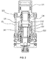
- FIG. 2 shows a state in which the through hole 151 connects the liquid inlet 1411 and the liquid outlet 1311 when the movable element 120 is screwed on the housing 110.
- FIG. 7 shows a state in which rotation of the blocking element 150 is caused in the process of unscrewing the movable element 120, so that a side wall of the blocking element 150 isolates the liquid inlet 1411 from the liquid outlet 1311.
- FIG. 4 shows a state in which a side wall of the blocking element 150 isolates the liquid inlet 1411 from the liquid outlet 1311 after the movable element 120 is detached.
- one end of the housing 110 defines a liquid refill port 111 configured for refilling liquid to the liquid storage chamber 130.
- the movable element 120 rotates relative to the housing 110, the movable element 120 is adapted for being detachably disposed at the liquid refill port 111.
- the movable element 120 drives the blocking element 150 to rotate through a friction between the movable element 120 and the blocking element 150. After the movable element 120 drives the blocking element 150 to rotate by a preset range of angles, the blocking element 150 is restricted and no longer rotates, but the movable element 120 is capable of continuing rotating so as to be detached from or disposed at the liquid refill port 111.
- the blocking element 150 has the setting of the range of rotation implemented by a scheme as below.
- One of the blocking element 150 and the inner sidewall 131 of the liquid storage chamber 130 has a protrusion 152 thereon while the other defines thereon a guide groove 1311 configured for accommodating the protrusion 152.
- the protrusion 152 is capable of rotating within a preset range of angles in the guide groove 1311, allowing the through hole 151 to connect the liquid inlet 1411 and the liquid outlet 1311, or allowing the sidewall of the blocking element 150 to cut off the communication between the liquid inlet 1411 and the liquid outlet 1311.
- the protrusion 152 is disposed on the blocking element 150, and the guide groove 1311 is correspondingly defined on the inner sidewall 131 of the liquid storage chamber 130.
- the movable element 120 is connected directly or indirectly on the blocking element 150 through a screw thread. While the movable element 120 is screwed on the blocking element 150, rotation of the blocking element 150 is caused such that the through hole 151 connects the liquid inlet 1411 and the liquid outlet 1311. While the movable element 120 is unscrewed, rotation of the blocking element 150 is caused such that the sidewall of the blocking element 150 cuts off the communication between the liquid inlet 1411 and the liquid outlet 1311.
- Such arrangement has beneficial effects as follows.
- a valve 160 configured for sealing the liquid refill port 111 is provided at the position of the liquid refill port 111.
- the valve 160 is capable of being pushed open by an external liquid refill container, so that a tobacco liquid can be refilled into the liquid storage chamber 130, and the valve 160 is capable of recovering from deformation and sealing again the liquid refill port 111 after the external liquid refill container is removed from the liquid refill port 111.
- the valve 160 is an elastic sheet pressed against an outer sidewall of the liquid storage chamber 130; the elastic sheet is sleeved on the blocking element 150, and is made of rubber or silicone material. The arrangement of the valve 160 makes liquid leakage less likely to occur at the liquid refill port 111.
- the blocking element 150 also may be restricted in a preset range of angles in a way as below.
- One of the blocking element 150 and the atomization assembly 140 has a protrusion thereon while the other defines thereon a guide groove capable of accommodating the protrusion.
- the protrusion is capable of rotating within a preset range of angles in the guide groove, allowing the through hole 151 to connect the liquid inlet 1411 and the liquid outlet 1311, or allowing the sidewall of the blocking element 150 to cut off the communication between the liquid inlet 1411 and the liquid outlet 1311.
- the liquid absorbing element 143 in the atomizer 100 can be set by a user not to keep long contact with the liquid in the liquid storage chamber 130, it is less likely that the liquid absorbing element 143 absorbs excessive liquid to lead to liquid leakage. Thus, a liquid leakage-proof function is realized.
- the risk of liquid leakage can be reduced at the liquid absorbing element 143.
- this embodiment discloses an electronic cigarette, which includes an atomizer 100 and a power supply 200.
- the atomizer 100 and the power supply 200 are coupled through a detachable threaded connection.
- the power supply 200 is configured for supplying power to the atomizer 100.
- the atomizer 100 is an atomizer 100 described in the Exemplary Embodiment 1.
Landscapes
- Engineering & Computer Science (AREA)
- Mechanical Engineering (AREA)
- Disinfection, Sterilisation Or Deodorisation Of Air (AREA)
- Nozzles (AREA)
Abstract
Description
- The present disclosure relates to the field of smoking sets, and particularly, to an atomizer for an electronic cigarette and an electronic cigarette including the same atomizer.
- As a substitute of traditional cigarettes, electronic cigarette is receiving more and more concerns and becoming more and more popular for it has advantages such as safety, convenience, health effects and environment friendliness in use. Electronic cigarettes available on the market all include an atomizer and a power supply assembly. The atomizer includes an atomization assembly and a liquid storage space configured for storing liquid. An air flow passage is defined in the liquid storage space. The atomization assembly further includes a liquid absorbing element and a heating element. When the heating element is activated, the liquid in the liquid absorbing element is aerosolized to generate an aerosol, which passes through the air flow passage to exit, thereby creating the feeling of tobacco smoking.
- In a typical electronic cigarette, the liquid absorbing element and the heating element which are disposed in the atomizer are accommodated in an atomization chamber. The liquid absorbing element penetrates the atomization chamber to keep constant contact with the liquid storage space which is positioned at the peripheral of the atomization chamber. However, with the atomizer of such structure, the liquid absorbing element often has liquid droplets leaked in a vibrating environment after the liquid absorbing element absorbs excessive liquid, and the dripped liquid flows out along the airflow passage, consequently causing negative experiences to consumers.
- In view of the drawbacks in the prior art, the technical problem to be solved by the present disclosure is providing an atomizer and an electronic cigarette which are capable of preventing a liquid absorbing element from keeping constant contact with a liquid storage space to absorb excessive liquid to lead to liquid leakage.
- In order to realize the above purpose of the present disclosure, the present disclosure employs an atomizer as follows. The atomizer for an electronic cigarette includes a housing, a liquid storage chamber arranged in the housing, and an atomization assembly arranged in the housing, the atomization assembly including a main body, a liquid absorbing element arranged in the main body, and a heating element arranged in the main body; the main body defines a liquid inlet, and the liquid storage chamber defines a liquid outlet fitting the liquid inlet in an inner sidewall thereof; a blocking element is further provided between an inner sidewall of the liquid storage chamber and the main body, and a through hole is defined on the blocking element; one end of the housing is provided with a movable element, which is capable of rotating relative to the housing to cause rotation of the blocking element, thus allowing the liquid inlet and the liquid outlet to be in communication through the through hole or allowing a sidewall of the blocking element to cut off the communication between the liquid inlet and the liquid outlet.
- Further, the movable element is capable of driving the blocking element to rotate within a preset range of angles.
- Further, the movable element drives the blocking element to rotate through a friction between the movable element and the blocking element.
- Further, one end of the housing defines a liquid refill port configured for refilling liquid to the liquid storage chamber; the movable element is detachably disposed at the liquid refill port in a manner of rotation relative to the housing; the movable element drives the blocking element to rotate through a friction between the movable element and the blocking element; and, after the movable element drives the blocking element to rotate by a preset range of angles, the blocking element is restricted and no longer rotates, but the movable element is capable of continuing rotating so as to be detached from or disposed at the liquid refill port.
- Preferably, one of the blocking element and the inner sidewall of the liquid storage chamber has a protrusion thereon while the other defines thereon a guide groove capable of accommodating the protrusion; and the protrusion is capable of rotating within a preset range of angles in the guide groove, allowing the through hole to connect the liquid inlet and the liquid outlet, or allowing the sidewall of the blocking element to cut off the communication between the liquid inlet and the liquid outlet.
- Preferably, one of the blocking element and the atomization assembly has a protrusion thereon while the other defines thereon a guide groove capable of accommodating the protrusion; and the protrusion is capable of rotating within a preset range of angles in the guide groove, allowing the through hole to connect the liquid inlet and the liquid outlet, or allowing the sidewall of the blocking element to cut off the communication between the liquid inlet and the liquid outlet.
- Preferably, the movable element is connected directly or indirectly on the blocking element through a screw thread; while the movable element is screwed on the blocking element, rotation of the blocking element is caused such that the through hole connects the liquid inlet and the liquid outlet; while the movable element is unscrewed, rotation of the blocking element is caused such that the sidewall of the blocking element cuts off the communication between the liquid inlet and the liquid outlet.
- Preferably, one end of the housing defines a liquid refill port configured for refilling liquid to the liquid storage chamber; the movable element is detachably disposed at the liquid refill port in a manner of rotation relative to the housing; and a valve configured for sealing the liquid refill port is provided at the position of the liquid refill port, wherein, the valve is capable of being pushed open by an external liquid refill container, so that a tobacco liquid can be refilled into the liquid storage chamber, and, the valve is capable of recovering from deformation and sealing again the liquid refill port after the external liquid refill container is removed from the liquid refill port.
- Preferably, the valve includes an elastic sheet pressed against an outer sidewall of the liquid storage chamber, the elastic sheet being sleeved on the blocking element.
- The present disclosure further discloses an electronic cigarette, which includes an atomizer and a power supply, wherein the power supply is configured for supplying power to the atomizer, and the atomizer is the atomizer described in any one of the above atomizers.
- Compared with the prior art, the atomizer and the liquid absorbing element of the electronic cigarette in the present disclosure can be set not to keep long contact with the liquid in the liquid storage chamber, consequently it is less likely that the liquid absorbing element absorbs excessive liquid to lead to liquid leakage. Thus, a liquid leakage-proof function is realized.
- Other beneficial effects of the present disclosure will be described in further detail in exemplary embodiments below.
-
-
FIG. 1 is a front view of an atomizer. -
FIG. 2 is a cross-sectional view of the atomizer ofFIG. 1 . -
FIG. 3 is a structural cross-sectional view of a blocking element sleeved outside a main body. -
FIG. 4 is a diagram illustrating a state in which a movable element is separated from a housing. -
FIG. 5 is a structural perspective view of an inner sidewall of a liquid storage chamber. -
FIG. 6 is a perspective view of a blocking element. -
FIG. 7 is a diagram illustrating a state in which a liquid inlet channel is blocked. -
FIG. 8 is a structural main view of an electronic cigarette. - The to-be-solved technical problem, the technical scheme and the beneficial effects of the disclosure will become more clearly understood from the detailed description of the present disclosure below taken in conjunction with accompanying drawings and embodiments. It should be understood that the exemplary embodiments described below are merely to illustrate, but to limit, the present disclosure.
- As shown in
FIG. 1 andFIG. 2 , this embodiment discloses anatomizer 100 for an electronic cigarette, which is coupled with apower supply 200 to form an electronic cigarette (referring toFIG. 8 ). Theatomizer 100 includes ahousing 110, and amovable element 120 in detachable connection with one end of thehousing 110. Amouthpiece 121 is further detachably connected on themovable element 120. - As shown in
FIG. 2 , thehousing 110 has provided therein aliquid storage chamber 130 configured for holding liquid and anatomization assembly 140. As shown inFIG. 3 , theatomization assembly 140 includes amain body 141, which has a liquid absorbingelement 143, aheating element 142 and anair flow passage 145 provided therein. Themouthpiece 121 is in communication with theairflow passage 145. Aliquid inlet 1411 is defined in themain body 141, and aliquid outlet 1311 fitting theliquid inlet 1411 is defined in aninner sidewall 131 of theliquid storage chamber 130. Ablocking element 150 is further provided between theinner sidewall 131 of theliquid storage chamber 130 and themain body 141, and a throughhole 151 is defined on theblocking element 150. Themovable element 120 is capable of rotating relative to thehousing 110 to cause rotation of theblocking element 150, thus allowing theliquid inlet 1411 and theliquid outlet 1311 to be in communication through thethrough hole 151 or allowing a sidewall of theblocking element 150 to cut off the communication between theliquid inlet 1411 and theliquid outlet 1311. In this embodiment, theliquid inlet 1411, theliquid outlet 1311 and the throughhole 151 are defined to match and fit one another in size and position. The liquid absorbingelement 143 is made of cotton material, glass fiber material or ceramic material. Theheating element 142 is vertically placed in a manner which is parallel to an axial direction of theatomizer 100. The liquid absorbingelement 143 is attached directly on an inner wall of themain body 141 to absorb the liquid influent from eachliquid inlet 1411. Theatomization assembly 140 aerosolizes the liquid to generate an aerosol, which is expelled from themouthpiece 121 after passing through theair flow passage 145. - As shown in
FIG. 2 andFIG. 3 , theblocking element 150 is sleeved on an outer surface of themain body 141. The rotation of theblocking element 150 caused by themovable element 120 is defined in a preset range of angles. It is understandable that the preset range of angles is set only needing to ensure that theliquid inlet 1411 and theliquid outlet 1311 can be in communication with each other or isolated from each other. In this embodiment, the number of theliquid inlet 1411 and the number of theliquid outlet 1311 are set to 4, respectively; the number of the throughhole 151 defined on the blockingelement 150 is set to 4 too; and the range of rotation of theblocking element 150 is set to 45 degrees. - In this embodiment, the
movable element 120 drives theblocking element 150 to rotate through a friction between themovable element 120 and theblocking element 150.FIG. 2 shows a state in which thethrough hole 151 connects theliquid inlet 1411 and theliquid outlet 1311 when themovable element 120 is screwed on thehousing 110.FIG. 7 shows a state in which rotation of theblocking element 150 is caused in the process of unscrewing themovable element 120, so that a side wall of theblocking element 150 isolates theliquid inlet 1411 from theliquid outlet 1311.FIG. 4 shows a state in which a side wall of the blockingelement 150 isolates theliquid inlet 1411 from theliquid outlet 1311 after themovable element 120 is detached. - As shown in
FIG. 4 , one end of thehousing 110 defines aliquid refill port 111 configured for refilling liquid to theliquid storage chamber 130. When themovable element 120 rotates relative to thehousing 110, themovable element 120 is adapted for being detachably disposed at theliquid refill port 111. Themovable element 120 drives the blockingelement 150 to rotate through a friction between themovable element 120 and the blockingelement 150. After themovable element 120 drives the blockingelement 150 to rotate by a preset range of angles, the blockingelement 150 is restricted and no longer rotates, but themovable element 120 is capable of continuing rotating so as to be detached from or disposed at theliquid refill port 111. - As shown in
FIG. 5 andFIG. 6 , the blockingelement 150 has the setting of the range of rotation implemented by a scheme as below. One of the blockingelement 150 and theinner sidewall 131 of theliquid storage chamber 130 has aprotrusion 152 thereon while the other defines thereon aguide groove 1311 configured for accommodating theprotrusion 152. Theprotrusion 152 is capable of rotating within a preset range of angles in theguide groove 1311, allowing the throughhole 151 to connect theliquid inlet 1411 and theliquid outlet 1311, or allowing the sidewall of the blockingelement 150 to cut off the communication between theliquid inlet 1411 and theliquid outlet 1311. In this embodiment, theprotrusion 152 is disposed on the blockingelement 150, and theguide groove 1311 is correspondingly defined on theinner sidewall 131 of theliquid storage chamber 130. - As shown in
FIG. 4 , themovable element 120 is connected directly or indirectly on the blockingelement 150 through a screw thread. While themovable element 120 is screwed on the blockingelement 150, rotation of the blockingelement 150 is caused such that the throughhole 151 connects theliquid inlet 1411 and theliquid outlet 1311. While themovable element 120 is unscrewed, rotation of the blockingelement 150 is caused such that the sidewall of the blockingelement 150 cuts off the communication between theliquid inlet 1411 and theliquid outlet 1311. Such arrangement has beneficial effects as follows. When a user screws off themovable element 120 to refill liquid into theliquid refill port 111, it is guaranteed that a liquid inlet channel defined between theliquid inlet 1411 and theliquid outlet 1311 is cut off by the blockingelement 150, so that liquid leakage is avoided at the liquid absorbingelement 143 during the process of the user refilling the liquid. When the user screws on themovable element 120, rotation of the blockingelement 150 is caused such that the throughhole 151 connects theliquid inlet 1411 and theliquid outlet 1311 to define a liquid inlet channel. - As shown in
FIG. 4 , avalve 160 configured for sealing theliquid refill port 111 is provided at the position of theliquid refill port 111. Thevalve 160 is capable of being pushed open by an external liquid refill container, so that a tobacco liquid can be refilled into theliquid storage chamber 130, and thevalve 160 is capable of recovering from deformation and sealing again theliquid refill port 111 after the external liquid refill container is removed from theliquid refill port 111. In this embodiment, thevalve 160 is an elastic sheet pressed against an outer sidewall of theliquid storage chamber 130; the elastic sheet is sleeved on the blockingelement 150, and is made of rubber or silicone material. The arrangement of thevalve 160 makes liquid leakage less likely to occur at theliquid refill port 111. - The above embodiment is just one of the preferred embodiments. Theoretically, in other embodiments, the blocking
element 150 also may be restricted in a preset range of angles in a way as below. One of the blockingelement 150 and theatomization assembly 140 has a protrusion thereon while the other defines thereon a guide groove capable of accommodating the protrusion. The protrusion is capable of rotating within a preset range of angles in the guide groove, allowing the throughhole 151 to connect theliquid inlet 1411 and theliquid outlet 1311, or allowing the sidewall of the blockingelement 150 to cut off the communication between theliquid inlet 1411 and theliquid outlet 1311. - In this embodiment, since the liquid absorbing
element 143 in theatomizer 100 can be set by a user not to keep long contact with the liquid in theliquid storage chamber 130, it is less likely that the liquid absorbingelement 143 absorbs excessive liquid to lead to liquid leakage. Thus, a liquid leakage-proof function is realized. In addition, when a user refills liquid into theliquid refill port 111, the risk of liquid leakage can be reduced at the liquid absorbingelement 143. - As shown in
FIG. 8 , this embodiment discloses an electronic cigarette, which includes anatomizer 100 and apower supply 200. Theatomizer 100 and thepower supply 200 are coupled through a detachable threaded connection. Thepower supply 200 is configured for supplying power to theatomizer 100. Theatomizer 100 is anatomizer 100 described in the Exemplary Embodiment 1. - The above content illustrates the principle and implementations of the present disclosure using exemplary embodiments. It is understandable that the above implementation is merely to help understand the present disclosure, and cannot be understood as a restriction to the present disclosure. For the ordinary skill in this field, any minor improvements or equivalent substitutions made to the structure shape or construction of the present disclosure according to the idea of the present disclosure are intended to fall within the scope of protection of the present disclosure.
Claims (10)
- An atomizer for an electronic cigarette, comprising a housing, a liquid storage chamber arranged in the housing, and an atomization assembly arranged in the housing, the atomization assembly comprising a main body, a liquid absorbing element arranged in the main body, and a heating element arranged in the main body, the main body defining a liquid inlet, the liquid storage chamber defining a liquid outlet fitting the liquid inlet in an inner sidewall thereof; wherein a blocking element is further provided between an inner sidewall of the liquid storage chamber and the main body, and a through hole is defined on the blocking element; wherein one end of the housing is provided with a movable element, which is capable of rotating relative to the housing to cause rotation of the blocking element, thus allowing the liquid inlet and the liquid outlet to be in communication through the through hole or allowing a sidewall of the blocking element to cut off the communication between the liquid inlet and the liquid outlet.
- The atomizer according to claim 1, wherein the movable element is capable of driving the blocking element to rotate within a preset range of angles.
- The atomizer according to claim 1 or 2, wherein the movable element drives the blocking element to rotate through a friction between the movable element and the blocking element.
- The atomizer according to claim 1, wherein one end of the housing defines a liquid refill port configured for refilling liquid to the liquid storage chamber; the movable element is detachably disposed at the liquid refill port in a manner of rotation relative to the housing; the movable element drives the blocking element to rotate through a friction between the movable element and the blocking element; and, after the movable element drives the blocking element to rotate by a preset range of angles, the blocking element is restricted and no longer rotates, but the movable element is capable of continuing rotating so as to be detached from or disposed at the liquid refill port.
- The atomizer according to claim 2 or 4, wherein one of the blocking element and the inner sidewall of the liquid storage chamber has a protrusion thereon while the other defines thereon a guide groove capable of accommodating the protrusion; and the protrusion is capable of rotating within a preset range of angles in the guide groove, allowing the through hole to connect the liquid inlet and the liquid outlet, or allowing the sidewall of the blocking element to cut off the communication between the liquid inlet and the liquid outlet.
- The atomizer according to claim 2 or 4, wherein one of the blocking element and the atomization assembly has a protrusion thereon while the other defines thereon a guide groove capable of accommodating the protrusion; and the protrusion is capable of rotating within a preset range of angles in the guide groove, allowing the through hole to connect the liquid inlet and the liquid outlet, or allowing the sidewall of the blocking element to cut off the communication between the liquid inlet and the liquid outlet.
- The atomizer according to claim 2 or 4, wherein the movable element is connected directly or indirectly on the blocking element through a screw thread; while the movable element is screwed on the blocking element, rotation of the blocking element is caused such that the through hole connects the liquid inlet and the liquid outlet; while the movable element is unscrewed, rotation of the blocking element is caused such that the sidewall of the blocking element cuts off the communication between the liquid inlet and the liquid outlet.
- The atomizer according to claim 1, wherein one end of the housing defines a liquid refill port configured for refilling liquid to the liquid storage chamber; the movable element is detachably disposed at the liquid refill port in a manner of rotation relative to the housing; and a valve configured for sealing the liquid refill port is provided at the position of the liquid refill port, wherein, the valve is capable of being pushed open by an external liquid refill container, so that tobacco liquid can be refilled into the liquid storage chamber, and, the valve is capable of recovering from deformation and sealing the liquid refill port again after the external liquid refill container is removed from the liquid refill port.
- The atomizer according to claim 8, wherein the valve comprises an elastic sheet pressed against an outer sidewall of the liquid storage chamber, the elastic sheet being sleeved on the blocking element.
- An electronic cigarette, comprising an atomizer and a power supply, the power supply being configured for supplying power to the atomizer, wherein the atomizer is the atomizer according to any one of claims 1 to 9.
Applications Claiming Priority (2)
| Application Number | Priority Date | Filing Date | Title |
|---|---|---|---|
| CN201611109535.8A CN106539133B (en) | 2016-12-02 | 2016-12-02 | Atomizer and electronic cigarette |
| CN201621329907.3U CN206284401U (en) | 2016-12-02 | 2016-12-02 | Atomizer and electronic cigarette |
Publications (3)
| Publication Number | Publication Date |
|---|---|
| EP3289899A2 true EP3289899A2 (en) | 2018-03-07 |
| EP3289899A3 EP3289899A3 (en) | 2018-04-18 |
| EP3289899B1 EP3289899B1 (en) | 2021-03-10 |
Family
ID=60569762
Family Applications (1)
| Application Number | Title | Priority Date | Filing Date |
|---|---|---|---|
| EP17205050.2A Active EP3289899B1 (en) | 2016-12-02 | 2017-12-02 | Atomizer and electronic cigarette having same |
Country Status (2)
| Country | Link |
|---|---|
| US (1) | US10506831B2 (en) |
| EP (1) | EP3289899B1 (en) |
Cited By (1)
| Publication number | Priority date | Publication date | Assignee | Title |
|---|---|---|---|---|
| EP3991584A1 (en) * | 2020-11-01 | 2022-05-04 | Shenzhen Eigate Technology Co., Ltd. | Glass atomizer |
Families Citing this family (14)
| Publication number | Priority date | Publication date | Assignee | Title |
|---|---|---|---|---|
| US10506831B2 (en) * | 2016-12-02 | 2019-12-17 | Shenzhen First Union Technology Co., Ltd. | Atomizer and electronic cigarette having same |
| USD836243S1 (en) * | 2017-08-15 | 2018-12-18 | Tuanfang Liu | E-cigarette atomizer |
| USD877975S1 (en) * | 2017-10-28 | 2020-03-10 | Vuber Technologies, Inc. | Atomizer |
| USD861978S1 (en) * | 2018-01-02 | 2019-10-01 | Shenzhen Smoore Technology Limited | Electronic cigarette atomizer |
| USD865278S1 (en) * | 2018-02-05 | 2019-10-29 | Shenzhen Transpring Enterprise Ltd. | Vape part |
| USD881463S1 (en) * | 2018-05-16 | 2020-04-14 | Changzhou Patent Electronic Technology Co., LTD | Atomizer head |
| CN110623301B (en) * | 2018-06-22 | 2024-06-04 | 湖南中烟工业有限责任公司 | Electron smog core and atomizer |
| USD917778S1 (en) * | 2018-10-22 | 2021-04-27 | Tuanfang Liu | Electronic cigarette |
| USD923867S1 (en) * | 2018-10-24 | 2021-06-29 | Shenzhen Smoore Technology Limited | Atomizer for an electronic cigarette |
| USD926358S1 (en) * | 2019-05-24 | 2021-07-27 | Tuanfang Liu | Electronic cigarette |
| USD926360S1 (en) * | 2019-07-08 | 2021-07-27 | Tuanfang Liu | Electronic cigarette |
| US12279647B2 (en) | 2019-12-23 | 2025-04-22 | Pax Labs, Inc. | Vaporizer cartridge |
| USD926365S1 (en) * | 2020-01-16 | 2021-07-27 | Shenzhen Eigate Technology Co., Ltd. | Electronic cigarette atomizer |
| USD1028336S1 (en) | 2021-06-22 | 2024-05-21 | Pax Labs, Inc. | Vaporizer cartridge |
Family Cites Families (9)
| Publication number | Priority date | Publication date | Assignee | Title |
|---|---|---|---|---|
| CN204994622U (en) * | 2015-09-10 | 2016-01-27 | 深圳市合元科技有限公司 | Atomizer and electronic cigarette |
| CN105192892B (en) | 2015-09-28 | 2018-09-21 | 深圳市新宜康科技股份有限公司 | Open fluid injection electronic smoke atomizer |
| CN105192893B (en) | 2015-10-13 | 2019-06-14 | 卓尔悦欧洲控股有限公司 | Atomizer and its electronic cigarette |
| CN205648912U (en) * | 2016-04-01 | 2016-10-19 | 深圳麦克韦尔股份有限公司 | Electronic cigarette and atomization device thereof |
| CN105962420B (en) * | 2016-06-28 | 2020-01-10 | 深圳麦克韦尔科技有限公司 | Electronic cigarette and atomizing device and atomizing component thereof |
| CN206284401U (en) | 2016-12-02 | 2017-06-30 | 深圳市合元科技有限公司 | Atomizer and electronic cigarette |
| US10506831B2 (en) * | 2016-12-02 | 2019-12-17 | Shenzhen First Union Technology Co., Ltd. | Atomizer and electronic cigarette having same |
| CN106539133B (en) | 2016-12-02 | 2024-05-03 | 深圳市合元科技有限公司 | Atomizer and electronic cigarette |
| USD836243S1 (en) * | 2017-08-15 | 2018-12-18 | Tuanfang Liu | E-cigarette atomizer |
-
2017
- 2017-12-02 US US15/829,915 patent/US10506831B2/en active Active
- 2017-12-02 EP EP17205050.2A patent/EP3289899B1/en active Active
Non-Patent Citations (1)
| Title |
|---|
| None |
Cited By (1)
| Publication number | Priority date | Publication date | Assignee | Title |
|---|---|---|---|---|
| EP3991584A1 (en) * | 2020-11-01 | 2022-05-04 | Shenzhen Eigate Technology Co., Ltd. | Glass atomizer |
Also Published As
| Publication number | Publication date |
|---|---|
| EP3289899A3 (en) | 2018-04-18 |
| EP3289899B1 (en) | 2021-03-10 |
| US10506831B2 (en) | 2019-12-17 |
| US20180153222A1 (en) | 2018-06-07 |
Similar Documents
| Publication | Publication Date | Title |
|---|---|---|
| EP3289899B1 (en) | Atomizer and electronic cigarette having same | |
| CN205196997U (en) | A reservoir and atomizer and electron cigarette for electron cigarette | |
| EP3487334B1 (en) | Refillable electronic cigarette clearomizer | |
| CN204409583U (en) | Electronic cigarette and electronic cigarette device thereof | |
| EP3305110B1 (en) | Atomizer for electronic cigarette | |
| CN104305526B (en) | Electronic cigarette and cigarette bomb tube thereof | |
| EP3340817B1 (en) | Liquid supply for electronic smoking device | |
| EP2949227B1 (en) | Atomizer assembly and atomizer for electronic cigarettes | |
| CN205456077U (en) | Atomizer and electronic cigarette | |
| CN104738816B (en) | Atomizer, electronic cigarette and liquid storage device suitable for replacement | |
| CN205456070U (en) | Liquid atomizer can be annotated and electron cigarette of this atomizer is used | |
| KR20110006928U (en) | Electronic cigarette | |
| EP3358972B1 (en) | Liquid supply for an electronic smoking device | |
| CN107846973B (en) | Liquid supply with spiral container | |
| CN204259818U (en) | Electronic cigarette and its pod tube | |
| JP7169998B2 (en) | Aerosol generation system with replaceable atomizer | |
| US20170105448A1 (en) | Liquefied Gas Powered Cigarette | |
| CN104125783A (en) | pod tube | |
| CN106539133B (en) | Atomizer and electronic cigarette | |
| CN105286090A (en) | Atomizer and electronic cigarette with the same | |
| CN207519629U (en) | Atomizer and electronic cigarette | |
| KR200454965Y1 (en) | E-cigarette cartridges | |
| CN109380767B (en) | Atomizers and electronic cigarettes | |
| CN206284401U (en) | Atomizer and electronic cigarette | |
| CN204426687U (en) | Electronic cigarette |
Legal Events
| Date | Code | Title | Description |
|---|---|---|---|
| PUAI | Public reference made under article 153(3) epc to a published international application that has entered the european phase |
Free format text: ORIGINAL CODE: 0009012 |
|
| STAA | Information on the status of an ep patent application or granted ep patent |
Free format text: STATUS: REQUEST FOR EXAMINATION WAS MADE |
|
| 17P | Request for examination filed |
Effective date: 20171230 |
|
| AK | Designated contracting states |
Kind code of ref document: A2 Designated state(s): AL AT BE BG CH CY CZ DE DK EE ES FI FR GB GR HR HU IE IS IT LI LT LU LV MC MK MT NL NO PL PT RO RS SE SI SK SM TR |
|
| AX | Request for extension of the european patent |
Extension state: BA ME |
|
| PUAL | Search report despatched |
Free format text: ORIGINAL CODE: 0009013 |
|
| RIC1 | Information provided on ipc code assigned before grant |
Ipc: A24F 47/00 20060101AFI20180308BHEP |
|
| AK | Designated contracting states |
Kind code of ref document: A3 Designated state(s): AL AT BE BG CH CY CZ DE DK EE ES FI FR GB GR HR HU IE IS IT LI LT LU LV MC MK MT NL NO PL PT RO RS SE SI SK SM TR |
|
| AX | Request for extension of the european patent |
Extension state: BA ME |
|
| GRAP | Despatch of communication of intention to grant a patent |
Free format text: ORIGINAL CODE: EPIDOSNIGR1 |
|
| STAA | Information on the status of an ep patent application or granted ep patent |
Free format text: STATUS: GRANT OF PATENT IS INTENDED |
|
| INTG | Intention to grant announced |
Effective date: 20200929 |
|
| GRAS | Grant fee paid |
Free format text: ORIGINAL CODE: EPIDOSNIGR3 |
|
| GRAA | (expected) grant |
Free format text: ORIGINAL CODE: 0009210 |
|
| STAA | Information on the status of an ep patent application or granted ep patent |
Free format text: STATUS: THE PATENT HAS BEEN GRANTED |
|
| AK | Designated contracting states |
Kind code of ref document: B1 Designated state(s): AL AT BE BG CH CY CZ DE DK EE ES FI FR GB GR HR HU IE IS IT LI LT LU LV MC MK MT NL NO PL PT RO RS SE SI SK SM TR |
|
| REG | Reference to a national code |
Ref country code: GB Ref legal event code: FG4D |
|
| REG | Reference to a national code |
Ref country code: AT Ref legal event code: REF Ref document number: 1368797 Country of ref document: AT Kind code of ref document: T Effective date: 20210315 Ref country code: CH Ref legal event code: EP |
|
| REG | Reference to a national code |
Ref country code: IE Ref legal event code: FG4D |
|
| REG | Reference to a national code |
Ref country code: DE Ref legal event code: R096 Ref document number: 602017034231 Country of ref document: DE |
|
| REG | Reference to a national code |
Ref country code: LT Ref legal event code: MG9D |
|
| PG25 | Lapsed in a contracting state [announced via postgrant information from national office to epo] |
Ref country code: HR Free format text: LAPSE BECAUSE OF FAILURE TO SUBMIT A TRANSLATION OF THE DESCRIPTION OR TO PAY THE FEE WITHIN THE PRESCRIBED TIME-LIMIT Effective date: 20210310 Ref country code: GR Free format text: LAPSE BECAUSE OF FAILURE TO SUBMIT A TRANSLATION OF THE DESCRIPTION OR TO PAY THE FEE WITHIN THE PRESCRIBED TIME-LIMIT Effective date: 20210611 Ref country code: FI Free format text: LAPSE BECAUSE OF FAILURE TO SUBMIT A TRANSLATION OF THE DESCRIPTION OR TO PAY THE FEE WITHIN THE PRESCRIBED TIME-LIMIT Effective date: 20210310 Ref country code: NO Free format text: LAPSE BECAUSE OF FAILURE TO SUBMIT A TRANSLATION OF THE DESCRIPTION OR TO PAY THE FEE WITHIN THE PRESCRIBED TIME-LIMIT Effective date: 20210610 Ref country code: BG Free format text: LAPSE BECAUSE OF FAILURE TO SUBMIT A TRANSLATION OF THE DESCRIPTION OR TO PAY THE FEE WITHIN THE PRESCRIBED TIME-LIMIT Effective date: 20210610 Ref country code: LT Free format text: LAPSE BECAUSE OF FAILURE TO SUBMIT A TRANSLATION OF THE DESCRIPTION OR TO PAY THE FEE WITHIN THE PRESCRIBED TIME-LIMIT Effective date: 20210310 |
|
| REG | Reference to a national code |
Ref country code: AT Ref legal event code: MK05 Ref document number: 1368797 Country of ref document: AT Kind code of ref document: T Effective date: 20210310 |
|
| REG | Reference to a national code |
Ref country code: NL Ref legal event code: MP Effective date: 20210310 |
|
| PG25 | Lapsed in a contracting state [announced via postgrant information from national office to epo] |
Ref country code: SE Free format text: LAPSE BECAUSE OF FAILURE TO SUBMIT A TRANSLATION OF THE DESCRIPTION OR TO PAY THE FEE WITHIN THE PRESCRIBED TIME-LIMIT Effective date: 20210310 Ref country code: LV Free format text: LAPSE BECAUSE OF FAILURE TO SUBMIT A TRANSLATION OF THE DESCRIPTION OR TO PAY THE FEE WITHIN THE PRESCRIBED TIME-LIMIT Effective date: 20210310 Ref country code: RS Free format text: LAPSE BECAUSE OF FAILURE TO SUBMIT A TRANSLATION OF THE DESCRIPTION OR TO PAY THE FEE WITHIN THE PRESCRIBED TIME-LIMIT Effective date: 20210310 |
|
| PG25 | Lapsed in a contracting state [announced via postgrant information from national office to epo] |
Ref country code: NL Free format text: LAPSE BECAUSE OF FAILURE TO SUBMIT A TRANSLATION OF THE DESCRIPTION OR TO PAY THE FEE WITHIN THE PRESCRIBED TIME-LIMIT Effective date: 20210310 |
|
| PG25 | Lapsed in a contracting state [announced via postgrant information from national office to epo] |
Ref country code: EE Free format text: LAPSE BECAUSE OF FAILURE TO SUBMIT A TRANSLATION OF THE DESCRIPTION OR TO PAY THE FEE WITHIN THE PRESCRIBED TIME-LIMIT Effective date: 20210310 Ref country code: CZ Free format text: LAPSE BECAUSE OF FAILURE TO SUBMIT A TRANSLATION OF THE DESCRIPTION OR TO PAY THE FEE WITHIN THE PRESCRIBED TIME-LIMIT Effective date: 20210310 Ref country code: SM Free format text: LAPSE BECAUSE OF FAILURE TO SUBMIT A TRANSLATION OF THE DESCRIPTION OR TO PAY THE FEE WITHIN THE PRESCRIBED TIME-LIMIT Effective date: 20210310 Ref country code: AT Free format text: LAPSE BECAUSE OF FAILURE TO SUBMIT A TRANSLATION OF THE DESCRIPTION OR TO PAY THE FEE WITHIN THE PRESCRIBED TIME-LIMIT Effective date: 20210310 |
|
| PG25 | Lapsed in a contracting state [announced via postgrant information from national office to epo] |
Ref country code: SK Free format text: LAPSE BECAUSE OF FAILURE TO SUBMIT A TRANSLATION OF THE DESCRIPTION OR TO PAY THE FEE WITHIN THE PRESCRIBED TIME-LIMIT Effective date: 20210310 Ref country code: RO Free format text: LAPSE BECAUSE OF FAILURE TO SUBMIT A TRANSLATION OF THE DESCRIPTION OR TO PAY THE FEE WITHIN THE PRESCRIBED TIME-LIMIT Effective date: 20210310 Ref country code: PL Free format text: LAPSE BECAUSE OF FAILURE TO SUBMIT A TRANSLATION OF THE DESCRIPTION OR TO PAY THE FEE WITHIN THE PRESCRIBED TIME-LIMIT Effective date: 20210310 Ref country code: PT Free format text: LAPSE BECAUSE OF FAILURE TO SUBMIT A TRANSLATION OF THE DESCRIPTION OR TO PAY THE FEE WITHIN THE PRESCRIBED TIME-LIMIT Effective date: 20210712 Ref country code: IS Free format text: LAPSE BECAUSE OF FAILURE TO SUBMIT A TRANSLATION OF THE DESCRIPTION OR TO PAY THE FEE WITHIN THE PRESCRIBED TIME-LIMIT Effective date: 20210710 |
|
| REG | Reference to a national code |
Ref country code: DE Ref legal event code: R097 Ref document number: 602017034231 Country of ref document: DE |
|
| PLBE | No opposition filed within time limit |
Free format text: ORIGINAL CODE: 0009261 |
|
| STAA | Information on the status of an ep patent application or granted ep patent |
Free format text: STATUS: NO OPPOSITION FILED WITHIN TIME LIMIT |
|
| PG25 | Lapsed in a contracting state [announced via postgrant information from national office to epo] |
Ref country code: ES Free format text: LAPSE BECAUSE OF FAILURE TO SUBMIT A TRANSLATION OF THE DESCRIPTION OR TO PAY THE FEE WITHIN THE PRESCRIBED TIME-LIMIT Effective date: 20210310 Ref country code: DK Free format text: LAPSE BECAUSE OF FAILURE TO SUBMIT A TRANSLATION OF THE DESCRIPTION OR TO PAY THE FEE WITHIN THE PRESCRIBED TIME-LIMIT Effective date: 20210310 Ref country code: AL Free format text: LAPSE BECAUSE OF FAILURE TO SUBMIT A TRANSLATION OF THE DESCRIPTION OR TO PAY THE FEE WITHIN THE PRESCRIBED TIME-LIMIT Effective date: 20210310 |
|
| 26N | No opposition filed |
Effective date: 20211213 |
|
| PG25 | Lapsed in a contracting state [announced via postgrant information from national office to epo] |
Ref country code: SI Free format text: LAPSE BECAUSE OF FAILURE TO SUBMIT A TRANSLATION OF THE DESCRIPTION OR TO PAY THE FEE WITHIN THE PRESCRIBED TIME-LIMIT Effective date: 20210310 |
|
| PG25 | Lapsed in a contracting state [announced via postgrant information from national office to epo] |
Ref country code: IT Free format text: LAPSE BECAUSE OF FAILURE TO SUBMIT A TRANSLATION OF THE DESCRIPTION OR TO PAY THE FEE WITHIN THE PRESCRIBED TIME-LIMIT Effective date: 20210310 |
|
| PG25 | Lapsed in a contracting state [announced via postgrant information from national office to epo] |
Ref country code: IS Free format text: LAPSE BECAUSE OF FAILURE TO SUBMIT A TRANSLATION OF THE DESCRIPTION OR TO PAY THE FEE WITHIN THE PRESCRIBED TIME-LIMIT Effective date: 20210710 |
|
| PG25 | Lapsed in a contracting state [announced via postgrant information from national office to epo] |
Ref country code: MC Free format text: LAPSE BECAUSE OF FAILURE TO SUBMIT A TRANSLATION OF THE DESCRIPTION OR TO PAY THE FEE WITHIN THE PRESCRIBED TIME-LIMIT Effective date: 20210310 |
|
| REG | Reference to a national code |
Ref country code: CH Ref legal event code: PL |
|
| REG | Reference to a national code |
Ref country code: BE Ref legal event code: MM Effective date: 20211231 |
|
| PG25 | Lapsed in a contracting state [announced via postgrant information from national office to epo] |
Ref country code: LU Free format text: LAPSE BECAUSE OF NON-PAYMENT OF DUE FEES Effective date: 20211202 Ref country code: IE Free format text: LAPSE BECAUSE OF NON-PAYMENT OF DUE FEES Effective date: 20211202 |
|
| PG25 | Lapsed in a contracting state [announced via postgrant information from national office to epo] |
Ref country code: BE Free format text: LAPSE BECAUSE OF NON-PAYMENT OF DUE FEES Effective date: 20211231 |
|
| PG25 | Lapsed in a contracting state [announced via postgrant information from national office to epo] |
Ref country code: LI Free format text: LAPSE BECAUSE OF NON-PAYMENT OF DUE FEES Effective date: 20211231 Ref country code: CH Free format text: LAPSE BECAUSE OF NON-PAYMENT OF DUE FEES Effective date: 20211231 |
|
| PG25 | Lapsed in a contracting state [announced via postgrant information from national office to epo] |
Ref country code: HU Free format text: LAPSE BECAUSE OF FAILURE TO SUBMIT A TRANSLATION OF THE DESCRIPTION OR TO PAY THE FEE WITHIN THE PRESCRIBED TIME-LIMIT; INVALID AB INITIO Effective date: 20171202 |
|
| PG25 | Lapsed in a contracting state [announced via postgrant information from national office to epo] |
Ref country code: CY Free format text: LAPSE BECAUSE OF FAILURE TO SUBMIT A TRANSLATION OF THE DESCRIPTION OR TO PAY THE FEE WITHIN THE PRESCRIBED TIME-LIMIT Effective date: 20210310 |
|
| PG25 | Lapsed in a contracting state [announced via postgrant information from national office to epo] |
Ref country code: MK Free format text: LAPSE BECAUSE OF FAILURE TO SUBMIT A TRANSLATION OF THE DESCRIPTION OR TO PAY THE FEE WITHIN THE PRESCRIBED TIME-LIMIT Effective date: 20210310 |
|
| PG25 | Lapsed in a contracting state [announced via postgrant information from national office to epo] |
Ref country code: MT Free format text: LAPSE BECAUSE OF FAILURE TO SUBMIT A TRANSLATION OF THE DESCRIPTION OR TO PAY THE FEE WITHIN THE PRESCRIBED TIME-LIMIT Effective date: 20210310 |
|
| P01 | Opt-out of the competence of the unified patent court (upc) registered |
Free format text: CASE NUMBER: APP_9641/2025 Effective date: 20250226 |
|
| PG25 | Lapsed in a contracting state [announced via postgrant information from national office to epo] |
Ref country code: TR Free format text: LAPSE BECAUSE OF FAILURE TO SUBMIT A TRANSLATION OF THE DESCRIPTION OR TO PAY THE FEE WITHIN THE PRESCRIBED TIME-LIMIT Effective date: 20210310 |
|
| PGFP | Annual fee paid to national office [announced via postgrant information from national office to epo] |
Ref country code: GB Payment date: 20251229 Year of fee payment: 9 |
|
| PGFP | Annual fee paid to national office [announced via postgrant information from national office to epo] |
Ref country code: FR Payment date: 20251230 Year of fee payment: 9 |
|
| PGFP | Annual fee paid to national office [announced via postgrant information from national office to epo] |
Ref country code: DE Payment date: 20251231 Year of fee payment: 9 |